

Page 1

AP3x10xN&5x10xN&5x30xN&6x10xN&7x10xN
Hardware Installation and
Maintenance Guide
Issue
Date 2015-08-05
HUAWEI TECHNOLOGIES CO., LTD.
12
Page 2

Copyright © Huawei Technologies Co., Ltd. 2015. All rights reserved.
No part of this document may be reproduced or transmitted in any form or by any means without prior written
consent of Huawei Technologies Co., Ltd.
Trademarks and Permissions
and other Huawei trademarks are trademarks of Huawei Technologies Co., Ltd.
All other trademarks and trade names mentioned in this document are the property of their respective holders.
Notice
The purchased products, services and features are stipulated by the contract made between Huawei and the
customer. All or part of the products, services and features described in this document may not be within the
purchase scope or the usage scope. Unless otherwise specified in the contract, all statements, information,
and recommendations in this document are provided "AS IS" without warranties, guarantees or representations
of any kind, either express or implied.
The information in this document is subject to change without notice. Every effort has been made in the
preparation of this document to ensure accuracy of the contents, but all statements, information, and
recommendations in this document do not constitute a warranty of any kind, express or implied.
Huawei Technologies Co., Ltd.
Address: Huawei Industrial Base
Bantian, Longgang
Shenzhen 518129
People's Republic of China
Website: http://e.huawei.com
Issue 12 (2015-08-05) Huawei Proprietary and Confidential
Copyright © Huawei Technologies Co., Ltd.
i
Page 3
AP3x10xN&5x10xN&5x30xN&6x10xN&7x10xN
Hardware Installation and Maintenance Guide About This Document
About This Document
Intended Audience
This document describes hardware features of AP3x10xN, 5x10xN, 5x30xN, 6x10xN and
7x10xN, and provides basic installation methods.
This document is intended for:
l Network planning engineers
l Hardware installation engineers
l Commissioning engineers
l Onsite maintenance engineers
l System maintenance engineers
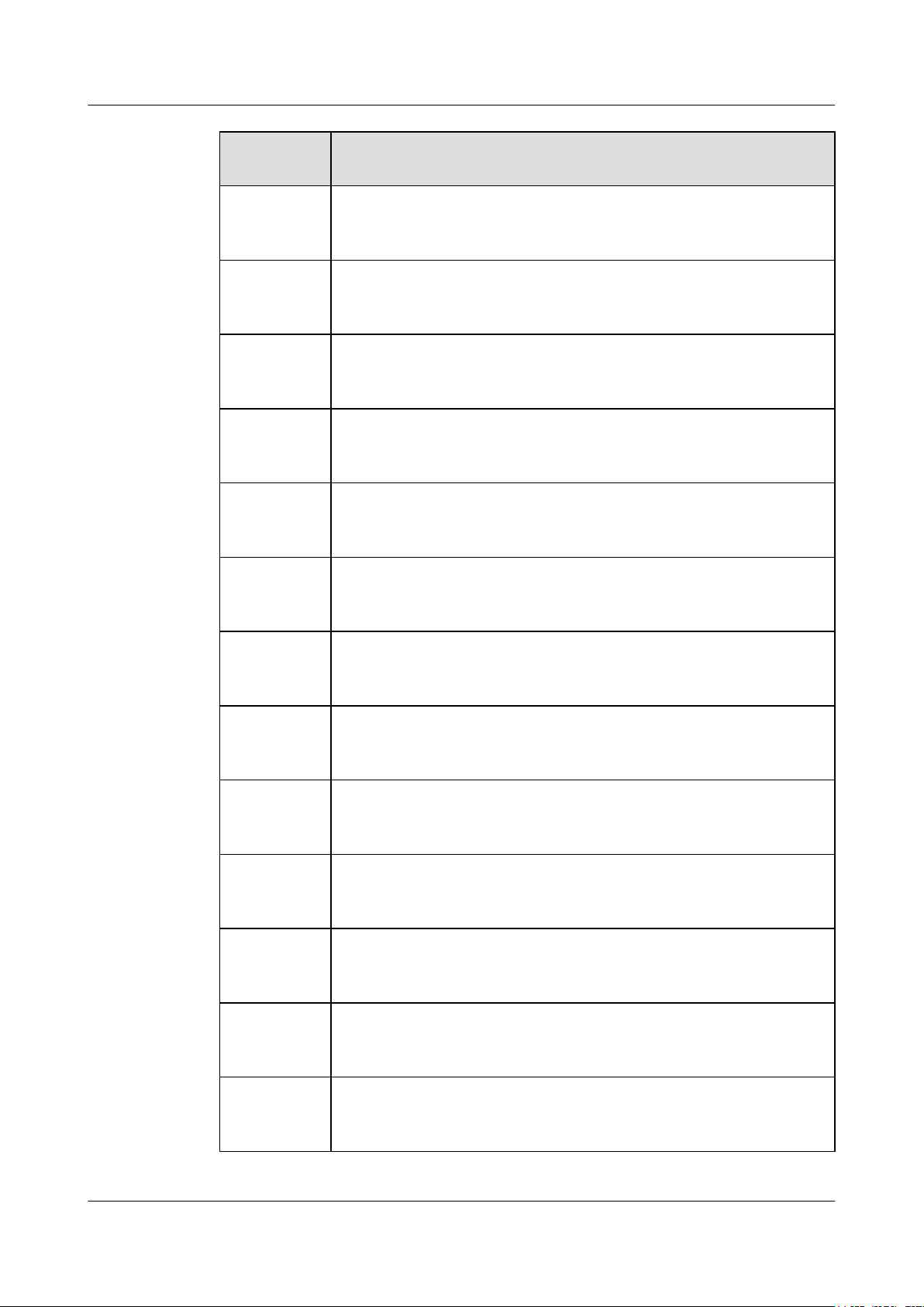
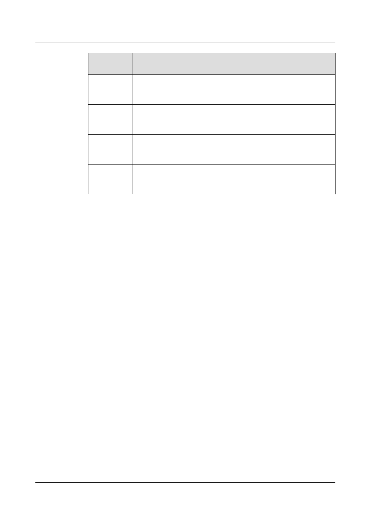
Symbol Conventions
The symbols that may be found in this document are defined as follows.
Symbol Description
Indicates an imminently hazardous situation
which, if not avoided, will result in death or
serious injury.
Indicates a potentially hazardous situation
which, if not avoided, could result in death or
serious injury.
Indicates a potentially hazardous situation
which, if not avoided, may result in minor or
moderate injury.
Indicates a potentially hazardous situation
which, if not avoided, could result in
equipment damage, data loss, performance
deterioration, or unanticipated results.
NOTICE is used to address practices not
related to personal injury.
Issue 12 (2015-08-05) Huawei Proprietary and Confidential
Copyright © Huawei Technologies Co., Ltd.
ii
Page 4

NOTE
AP3x10xN&5x10xN&5x30xN&6x10xN&7x10xN
Hardware Installation and Maintenance Guide
Symbol Description
Change History
Changes between document issues are cumulative. The latest document issue contains all
changes made in previous issues.
Issue 12 (2015-08-05)
This version has the following updates:
About This Document
Calls attention to important information, best
practices and tips.
NOTE is used to address information not
related to personal injury, equipment damage,
and environment deterioration.
Updated the packing list.
Issue 11 (2015-05-18)
This version has the following updates:
The following information is modified:
l Added the command to check AP running status in V200R006C00.
l Added descriptions about PoE fault troubleshooting.
Issue 10 (2014-12-05)
This version has the following updates:
The following information is added:
l 1.4 Ordering Information.
Issue 09 (2014-07-30)
This version has the following updates:
The following information is modified:
l Optimized the installation steps.
The following information is added:
l Logging in to the AP using STelnet.
Issue 08 (2013-04-10)
This version has the following updates:
The following information is added:
Issue 12 (2015-08-05) Huawei Proprietary and Confidential
Copyright © Huawei Technologies Co., Ltd.
iii
Page 5

AP3x10xN&5x10xN&5x30xN&6x10xN&7x10xN
Hardware Installation and Maintenance Guide
l AP5030DN and AP5130DN installation guide
l Note: The network cable cannot exceed 100 meters.
Issue 07 (2014-01-15)
This version has the following updates:
Optimized the manual.
Issue 06 (2013-09-30)
This version has the following updates:
The following information is modified:
l AP's default IP address and login password
Issue 05 (2013-06-29)
About This Document
This version has the following updates:
The following information is modified:
l Figure for converting SMA connectors to type—N connectors
Issue 04 (2013-04-30)
This version has the following updates:
The following information is modified:
l Figure of the sheet metal mounting brackets delivered with APs
Issue 03 (2013-01-30)
This version has the following updates:
The following information is added:
l Descriptions about power adapters delivered with APs
l Section: Removing an AP
Issue 02 (2012-12-31)
This version has the following updates:
The following information is added:
l Power adapter cable connection figure
Issue 01 (2012-10-31)
Initial commercial release
Issue 12 (2015-08-05) Huawei Proprietary and Confidential
Copyright © Huawei Technologies Co., Ltd.
iv
Page 6

AP3x10xN&5x10xN&5x30xN&6x10xN&7x10xN
Hardware Installation and Maintenance Guide
Contents
Contents
About This Document.....................................................................................................................ii
1 Indoor AP Overview.....................................................................................................................1
1.1 Device Structure.............................................................................................................................................................1
1.2 Indicator Description......................................................................................................................................................4
1.3 Basic Specifications........................................................................................................................................................7
1.4 Ordering Information....................................................................................................................................................10
2 AP Installation.............................................................................................................................14
2.1 Preparing for Installation..............................................................................................................................................14
2.2 Installation Flowchart...................................................................................................................................................15
2.3 Unpacking the Equipment............................................................................................................................................17
2.4 Determining the Installation Position...........................................................................................................................18
2.5 Installing the AP...........................................................................................................................................................19
2.5.1 Wall Mounting...........................................................................................................................................................20
2.5.2 Ceiling Mounting.......................................................................................................................................................22
2.5.3 T-rail Mounting.........................................................................................................................................................23
2.5.4 Removing an AP........................................................................................................................................................24
2.6 Connecting Cables........................................................................................................................................................25
2.7 Installing the Security Lock..........................................................................................................................................29
2.8 Checking the AP After Installation..............................................................................................................................29
2.9 Powering on the AP......................................................................................................................................................30
3 Logging In to the AP...................................................................................................................31
3.1 Logging In to the AP Through the Console Port..........................................................................................................31
3.2 Logging In to the AP Using STelnet............................................................................................................................31
3.3 Logging In to the AP Using Telnet..............................................................................................................................33
3.4 Logging In to the AP Using a Web Client....................................................................................................................34
4 Hardware Failures.......................................................................................................................35
4.1 A Device Fails to Be Powered On................................................................................................................................35
4.2 An Optical Interface Cannot Turn Up..........................................................................................................................36
5 Appendix.......................................................................................................................................38
5.1 On-site Cable Assembly and Installation.....................................................................................................................38
Issue 12 (2015-08-05) Huawei Proprietary and Confidential
Copyright © Huawei Technologies Co., Ltd.
v
Page 7

AP3x10xN&5x10xN&5x30xN&6x10xN&7x10xN
Hardware Installation and Maintenance Guide Contents
5.1.1 Cable Assembly Precautions.....................................................................................................................................38
5.1.2 Assembling Power Cables.........................................................................................................................................39
5.1.3 Assembling Ethernet Cables......................................................................................................................................48
5.1.4 Installing Cable Accessories......................................................................................................................................62
5.1.5 Replacing the Mold of the Crimping Tool................................................................................................................77
5.2 Environmental Requirements for Device Operation....................................................................................................81
5.2.1 Environmental Requirements for an Equipment Room............................................................................................81
5.2.2 Requirements for Power Supply................................................................................................................................88
5.3 Equipment Grounding Specifications...........................................................................................................................91
5.3.1 General Grounding Specifications.............................................................................................................................91
5.3.2 Grounding Specifications for an Equipment Room..................................................................................................91
5.3.3 Grounding Specifications for Devices.......................................................................................................................91
5.3.4 Grounding Specifications for Communications Power Supply.................................................................................92
5.3.5 Grounding Specifications for Signal Cables.............................................................................................................93
5.3.6 Specifications for Laying Out Grounding Cables.....................................................................................................93
5.4 Engineering Labels for Cables.....................................................................................................................................94
5.4.1 Introduction to Labels................................................................................................................................................94
5.4.2 Engineering Labels for Optical Fibers.....................................................................................................................102
5.4.3 Engineering Labels for Network Cables.................................................................................................................105
5.4.4 Engineering Labels for User Cables........................................................................................................................106
5.4.5 Engineering Labels for Power Cables.....................................................................................................................107
5.5 Guide to Using Optical Modules................................................................................................................................110
5.6 Fault Tag.....................................................................................................................................................................113
Issue 12 (2015-08-05) Huawei Proprietary and Confidential
Copyright © Huawei Technologies Co., Ltd.
vi
Page 8
1
2
3
6
7
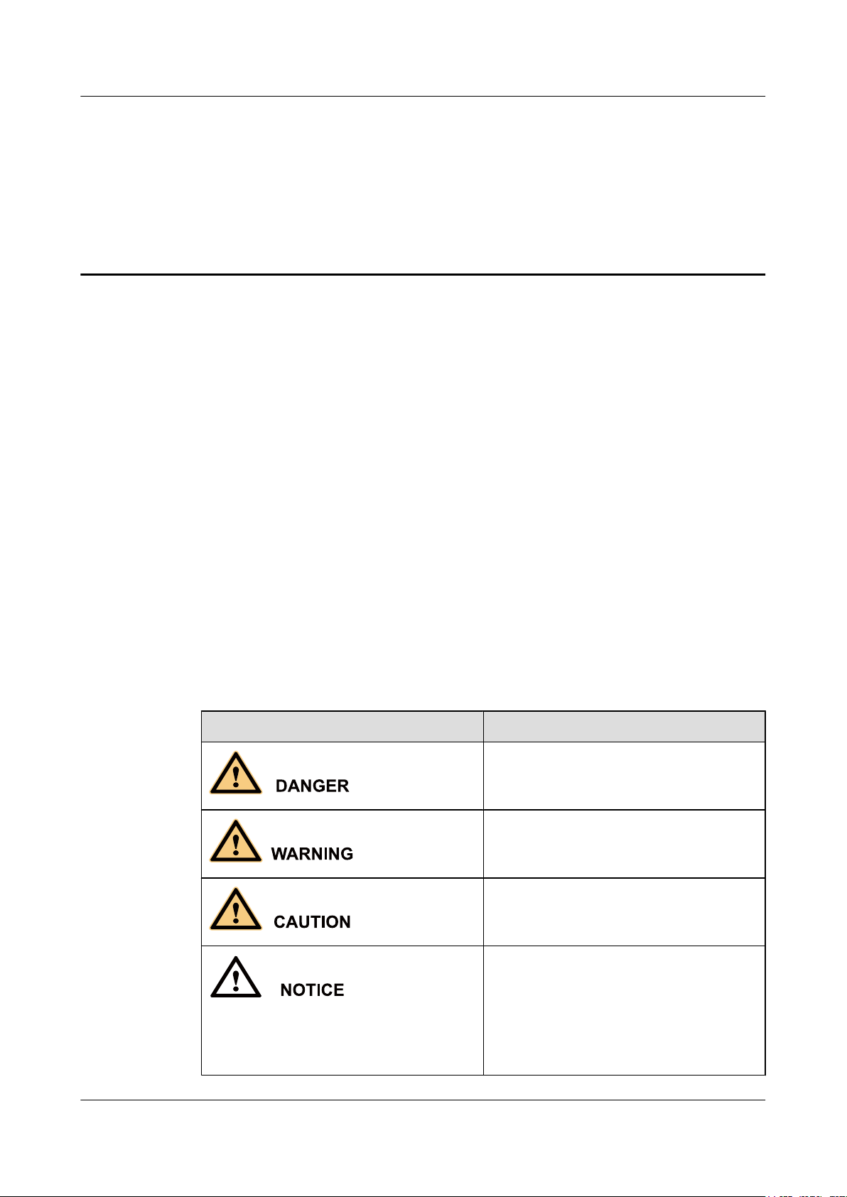
ConsoleETH/PoEDefaultDC 12V
AP3x10xN&5x10xN&5x30xN&6x10xN&7x10xN
Hardware Installation and Maintenance Guide 1 Indoor AP Overview
1 Indoor AP Overview
1.1 Device Structure
Figures in Table 1-1 show the appearance of indoor APs.
CAUTION
There is a scald warning label attached on some devices, warning you not to touch the device
after the device has been operating for a long time.
Table 1-1 Appearance of indoor APs
Product Model Appearance
AP3010DN-AGN
AP5010DN-AGN
AP5010SN-GN
AP6010DN-AGN
AP6010SN-GN
Issue 12 (2015-08-05) Huawei Proprietary and Confidential
Copyright © Huawei Technologies Co., Ltd.
1
Page 9
2
6
5 74 1
Console GE1 GE0/PoE DC 12V
2
6
5 7
10
4 1
Console GE1 GE0/PoE DC 12V
2.4G
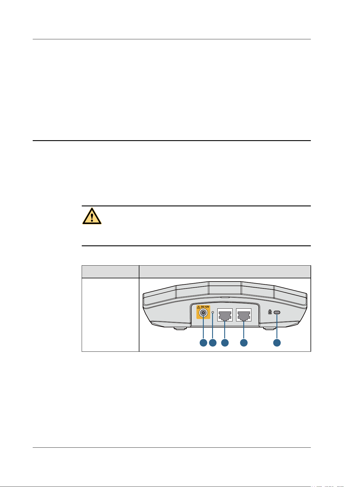
Console ETH/PoE Default DC 12V
8 3 1116 2
AP3x10xN&5x10xN&5x30xN&6x10xN&7x10xN
Hardware Installation and Maintenance Guide 1 Indoor AP Overview
Product Model Appearance
AP5030DN
AP5130DN
AP6310SN-GN
Issue 12 (2015-08-05) Huawei Proprietary and Confidential
Copyright © Huawei Technologies Co., Ltd.
2
Page 10
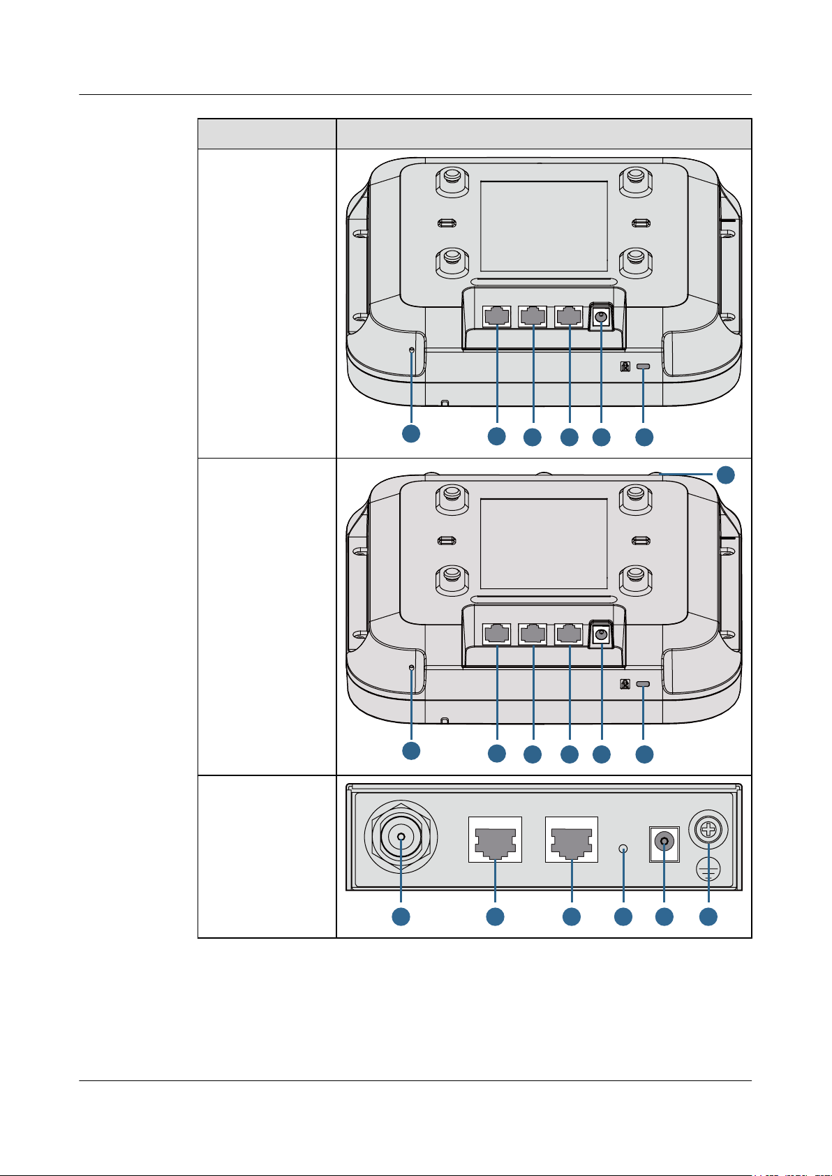
9 3 1 8211 6 7
Console ETH/PoE Default DC 12V
Console ETH/PoE DC 12VDefault
11 6 2 73 1 8
AP3x10xN&5x10xN&5x30xN&6x10xN&7x10xN
Hardware Installation and Maintenance Guide 1 Indoor AP Overview
Product Model Appearance
AP7110DN-AGN
AP7110SN-GN
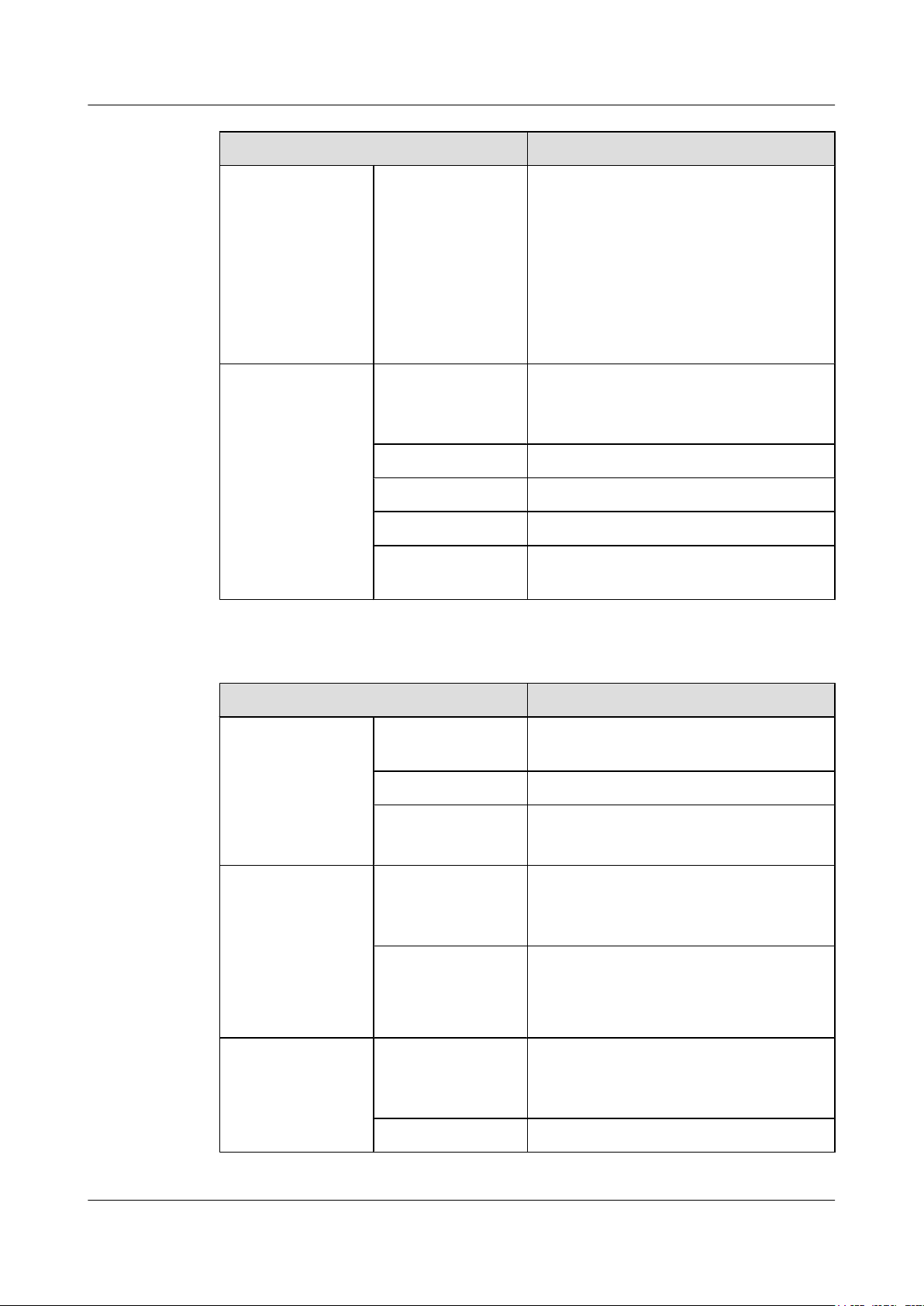
Table 1-2 describes interfaces on indoor APs.
Table 1-2 Interfaces on indoor APs
No. Name Description
1 DC 12 V DC power socket: connects a 12 V power
adapter to the AP.
2 Default Reset button: restores factory settings if you
hold down the button more than 3s.
3 ETH/PoE 10/100/1000M bit/s interface: connects to the
wired Ethernet. The interface can connect to
a PoE power supply to provide power for the
AP.
4 GE1 10/100/1000M bit/s interface: connects to the
wired Ethernet.
5 GE0/PoE 10/100/1000M bit/s interface: connects to the
wired Ethernet. The interface can connect to
a PoE power supply to provide power for the
AP.
6 Console Console interface: connects to a maintenance
7 Security slot Connects to a security lock.
8 2.4 GHz antenna port Connects a 2.4 GHz antenna to the AP.
Issue 12 (2015-08-05) Huawei Proprietary and Confidential
Copyright © Huawei Technologies Co., Ltd.
terminal for AP configuration and
management.
3
Page 11
AP3x10xN&5x10xN&5x30xN&6x10xN&7x10xN
Hardware Installation and Maintenance Guide 1 Indoor AP Overview
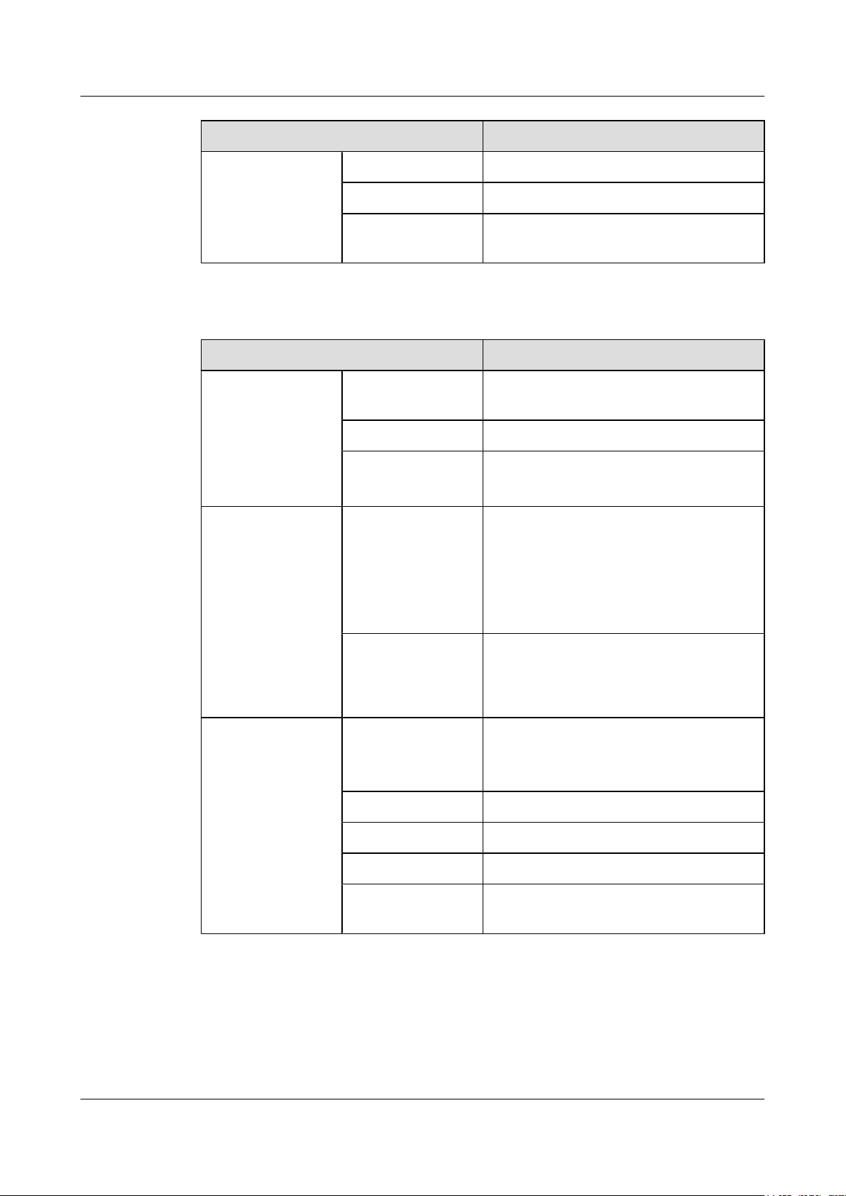
No. Name Description
9 5 GHz antenna port Connects a 5 GHz antenna to the AP.
10 Dual-band antenna
port
11 Device ground screw Connects a ground cable to the AP.
1.2 Indicator Description
Indoor AP series products provide a single indicator or multiple indicators.
l The AP3010DN-AGN, AP5010DN-AGN, AP5010SN-GN, AP5030DN, AP5130DN,
AP6010DN-AGN, and AP6010SN-GN provide only a single indicator.
l The AP6310SN-GN, AP7110DN-AGN, and AP7110SN-GN provide multiple indicators:
SYS indicator, Link indicator, and Wireless indicator.
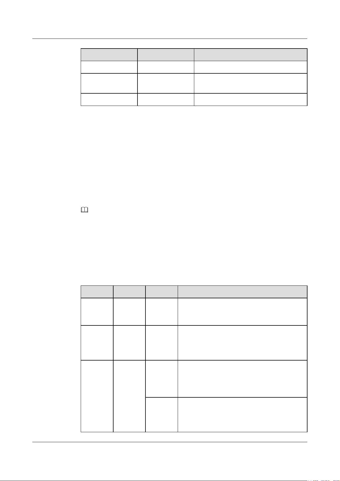
The following table describes indicators on indoor APs.
NOTE
l Indicator colors may vary slightly at different temperature.
l After a Fit AP is powered on, you can run the led off command on the AC to turn off all AP indicators.
To restore the indicators to normal working status, run the led on command. Indicators on a Fat AP
cannot be turned off using the led off command.
Connects a dual-band antenna to the AP.
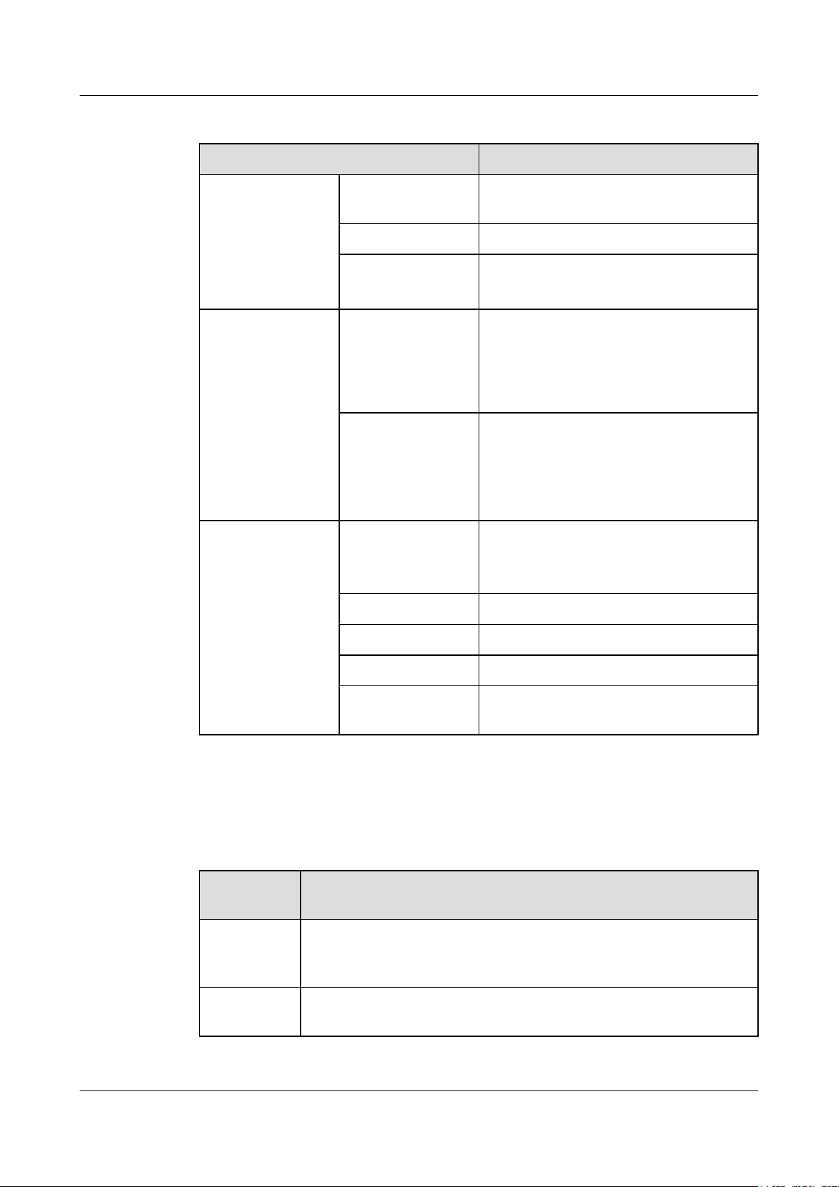
Single indicator and SYS indicator
Table 1-3 Descriptions about the single indicator and SYS indicator
Type Color Status Description
Default
status after
power-on
Software
startup
status
Running
status
Green Steady on The AP is just powered on and the software is not
Green Steady on
Green Blinking
after
blinking
once
once every
2s (0.5 Hz)
Blinking
once every
5s (0.2 Hz)
started yet.
After the system is reset and starts uploading the
software, the indicator blinks green once. Until the
software is uploaded and started, the indicator
remains steady green.
l The system is running properly, the Ethernet
connection is normal, and STAs are associated
with the AP.
l The system enters the Uboot CLI.
The system is running properly, the Ethernet
connection is normal, and no STA is associated with
the AP. The system is in low power consumption
state.
Issue 12 (2015-08-05) Huawei Proprietary and Confidential
Copyright © Huawei Technologies Co., Ltd.
4
Page 12
AP3x10xN&5x10xN&5x30xN&6x10xN&7x10xN
Hardware Installation and Maintenance Guide 1 Indoor AP Overview
Type Color Status Description
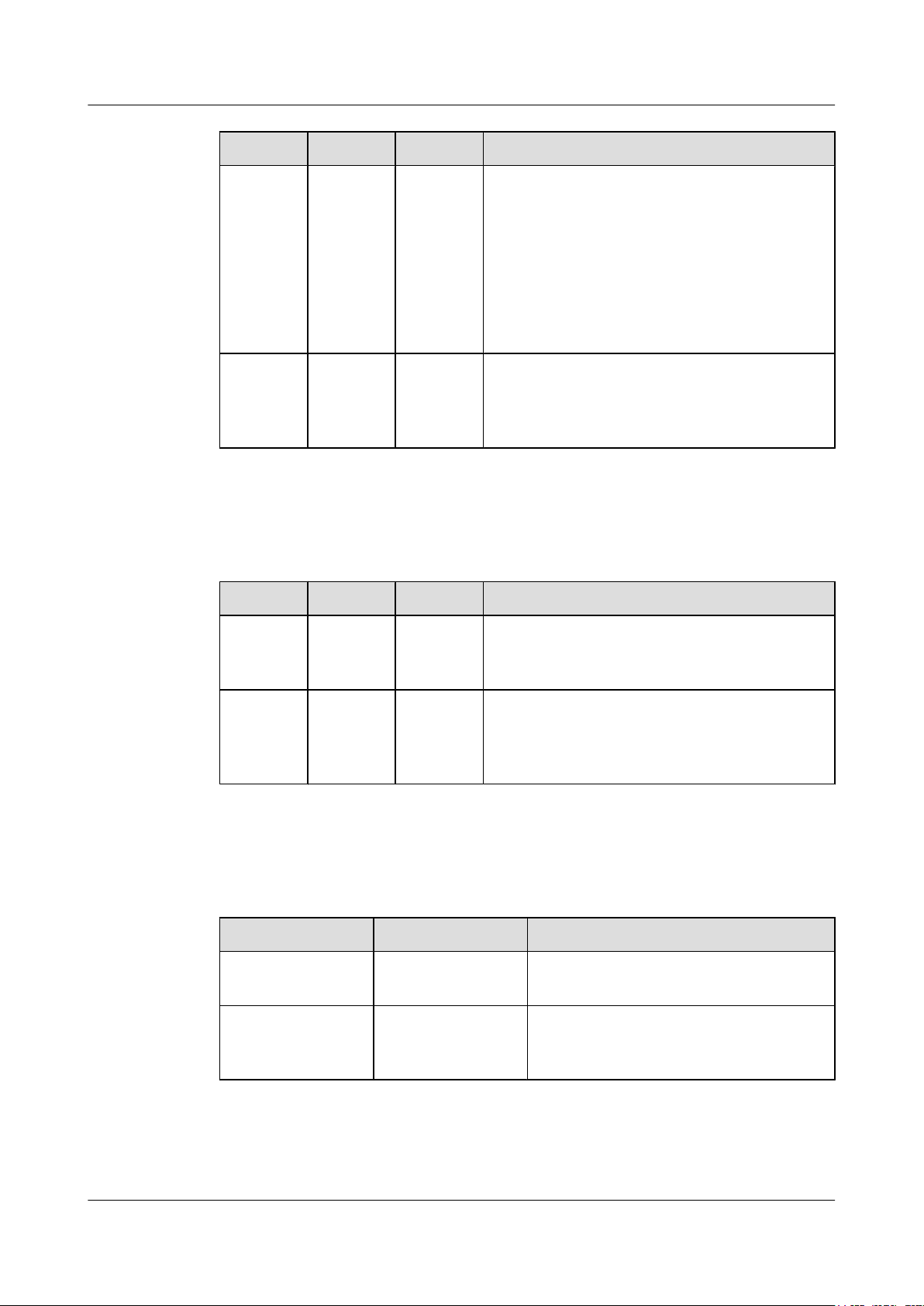
Link indicator
Alarm Green Blinking
once every
0.25s (4
Hz)
Fault Red Steady on A fault that affects services has occurred, such as a
Table 1-4 Descriptions about the Link indicator
Type Color Status Description
l The software is being upgraded.
l After the software is uploaded and started, the AP
working in Fit AP mode requests to go online on
the AC and maintains this state until it goes
online successfully on the AC (before the
CAPWAP link is established).
l The AP working in Fit AP mode fails to go online
on the AC (the CAPWAP link disconnects).
DRAM detection failure or system software loading
failure. The fault cannot be automatically rectified
and must be rectified manually.
LINK Green Steady on The system is running properly, the Ethernet
ACT Green Blinking The system is running properly, the Ethernet
Wireless indicator
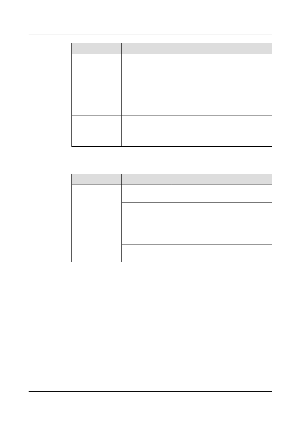
Table 1-5 Descriptions about the Wireless indicator in traffic volume mode
Color Status Description
Yellow/green Off Radios are disabled, and no STA is connected
Yellow/green Steady on The AP has STAs connected to the 2.4 GHz
connection is normal, and no data is being
transmitted.
connection is normal, and the AP is transmitting
data. The indicator blinks more quickly when more
data is being transmitted.
to the AP.
radio or 5 GHz radio, but no data is being
transmitted.
Issue 12 (2015-08-05) Huawei Proprietary and Confidential
Copyright © Huawei Technologies Co., Ltd.
5
Page 13
AP3x10xN&5x10xN&5x30xN&6x10xN&7x10xN
Hardware Installation and Maintenance Guide 1 Indoor AP Overview
Color Status Description
Green Blinking The AP has STAs connected to the 2.4 GHz
radio and is transmitting data. The indicator
blinks more quickly when more data is being
transmitted.
Yellow Blinking The AP has STAs connected to the 5 GHz
radio and is transmitting data. The indicator
blinks more quickly when more data is being
transmitted.
Yellow/green Blinking
alternatively
The AP has STAs connected to both the 2.4
GHz radio and 5 GHz radio. The indicator
blinks more quickly when more data is being
transmitted.
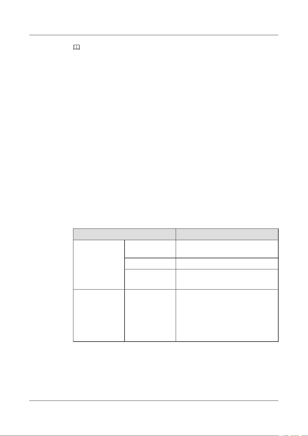
Table 1-6 Descriptions about the Wireless indicator in signal strength mode
Color Status Description
Yellow/green Off The AP is not transmitting or receiving data
or the signal strength is extremely low.
Blinking once every
2s (0.5 Hz)
Blinking green once
every 0.25 seconds (4
The AP is transmitting or receiving data
normally, and the signal strength is low.
The AP is transmitting or receiving data
normally, and the signal strength is medium.
Hz)
Steady on The AP is transmitting or receiving data
normally, and the signal strength is high.
Issue 12 (2015-08-05) Huawei Proprietary and Confidential
Copyright © Huawei Technologies Co., Ltd.
6
Page 14
AP3x10xN&5x10xN&5x30xN&6x10xN&7x10xN
Hardware Installation and Maintenance Guide 1 Indoor AP Overview
NOTE
When the WDS/Mesh function is enabled on an AP, the blinking frequency of its Wireless indicator
indicates the receive signal strength on the WDS/Mesh connection by default. After you connect an AP to
a WDS/Mesh network, you can run the wifi-light { signal-strength | traffic } command on the AC to
make the Wireless indicator blinking frequency indicate receive signal strength or service traffic rate.
l wifi-light signal-strength:
l If the Mesh function is enabled on the AP, the blinking frequency of the Wireless indicator reflects
the weakest signal strength of all neighboring APs.
l If WDS is enabled on an AP, the blinking frequency of the Wireless indicator reflects the strength
of signals received from a WDS AP.
l If the AP works in leaf mode, the blinking frequency of the Wireless indicator reflects the
strength of signals received from a middle AP.
l If the AP works in middle mode, the blinking frequency of the Wireless indicator reflects the
strength of signals received from a root AP.
l If the AP works in root mode, the blinking frequency of the Wireless indicator reflects the
weakest signal strength of middle APs.
l wifi-light traffic: allows the Wireless indicator to reflect the service traffic volume on the radio.
When an AP functions as a Fat AP, the Wireless indicator of the AP can not reflect the signal strength.
The AP6310SN-GN does not support WDS/Mesh functions; therefore, the Wireless indicator of the
AP6310SN-GN does not indicate the signal strength.
1.3 Basic Specifications
Table 1-7 Basic specifications of the AP3010DN-AGN, AP5010SN-GN, AP5010DN-AGN,
AP6010DN-AGN, and AP6010SN-GN
Item Description
Technical
specifications
Power specifications Power input
Dimensions (H x W xD)50 mm x 180 mm x 180 mm
Weight 0.4 kg
System memory
l 256 MB DDR2
l 32 MB flash memory
l DC 12 V ± 10%
l PoE power supply: in compliance with
IEEE 802.3af/at
NOTE
The AP6010DN-AGN and AP6010SN-GN cannot
use the PoE power supply and DC power supply
simultaneously.
Issue 12 (2015-08-05) Huawei Proprietary and Confidential
Copyright © Huawei Technologies Co., Ltd.
7
Page 15
AP3x10xN&5x10xN&5x30xN&6x10xN&7x10xN
Hardware Installation and Maintenance Guide 1 Indoor AP Overview
Item Description
Environment
specifications
Maximum power
consumption
l AP3010DN-AGN: 9.5 W
l AP5010DN-AGN: 9.5 W
l AP5010SN-GN: 6.0 W
l AP6010DN-AGN: 10.2 W
l AP6010SN-GN: 6.5 W
NOTE
The actual maximum power consumption depends
on local laws and regulations.
Operating
temperature and
altitude
-60 m to +1800 m: -10°C to +50°C
1800 m to 5000 m: Temperature decreases by
1°C every time the altitude increases 300 m.
Storage temperature -40°C to +70°C
Operating humidity 5% to 95% (non-condensing)
IP grade IP31
Atmospheric
70 kPa to 106 kPa
pressure
Table 1-8 Basic specifications of the AP5030DN and AP5130DN
Item Description
Technical
Dimensions (H x W xD)53 mm x 220 mm x 220 mm
specifications
Weight 1.0 kg
System memory
l 256 MB DDR2
l 32 MB flash memory
Power specifications Power input
l DC 12 V ± 10%
l PoE power: -48 V DC (in compliance with
IEEE 802.3af/at)
Environment
specifications
Maximum power
consumption
Operating
temperature and
altitude
12.95 W
NOTE
The actual maximum power consumption depends
on local laws and regulations.
-60 m to +1800 m: -10°C to +50°C
1800 m to 5000 m: Temperature decreases by
1°C every time the altitude increases 300 m.
Storage temperature -40°C to +70°C
Issue 12 (2015-08-05) Huawei Proprietary and Confidential
Copyright © Huawei Technologies Co., Ltd.
8
Page 16
AP3x10xN&5x10xN&5x30xN&6x10xN&7x10xN
Hardware Installation and Maintenance Guide
Item Description
Operating humidity 5% to 95% (non-condensing)
IP grade IP41
1 Indoor AP Overview
Atmospheric
70 kPa to 106 kPa
pressure
Table 1-9 Basic specifications of the AP6310SN-GN
Item Description
Technical
Dimensions (H x W xD)35 mm x 150 mm x 130 mm
specifications
Weight 0.6 kg
System memory
l 128 MB DDR2
l 32 MB flash memory
Power specifications Power input
l DC 12 V ± 10%
l PoE power supply: -48 V DC (in
compliance with IEEE 802.3af/at)
NOTE
The AP6310SN-GN cannot use the PoE power
supply and DC power supply simultaneously.
Environment
specifications
Maximum power
consumption
Operating
temperature and
altitude
8.3 W
NOTE
The actual maximum power consumption depends
on local laws and regulations.
-60 m to +1800 m: -10°C to +50°C
1800 m to 5000 m: Temperature decreases by
1°C every time the altitude increases 300 m.
Storage temperature -40°C to +70°C
Operating humidity 5% to 95% (non-condensing)
IP grade IP31
Atmospheric
70 kPa to 106 kPa
pressure
Issue 12 (2015-08-05) Huawei Proprietary and Confidential
Copyright © Huawei Technologies Co., Ltd.
9
Page 17
AP3x10xN&5x10xN&5x30xN&6x10xN&7x10xN
Hardware Installation and Maintenance Guide 1 Indoor AP Overview
Table 1-10 Basic specifications of the AP7110SN-GN and AP7110DN-AGN
Item Description
Technical
specifications
Power specifications Power input
Environment
specifications
Dimensions (H x W xD)45 mm x 200 mm x 200 mm
Weight 1.0 kg
System memory
Maximum power
consumption
Operating
temperature and
altitude
l 256 MB DDR3
l 32 MB flash memory
l DC 12 V ± 10%
l PoE power: -48 V DC
– AP7110SN-GN: IEEE 802.3af/at
– AP7110DN-AGN: IEEE 802.3at
l AP7110DN-AGN: 15.7 W
l AP7110SN-GN: 8.7 W
NOTE
The actual maximum power consumption depends
on local laws and regulations.
-60 m to +1800 m: -10°C to +55°C
1800 m to 5000 m: Temperature decreases by
1°C every time the altitude increases 300 m.
Storage temperature -40°C to +70°C
Operating humidity 5% to 95% (non-condensing)
IP grade IP41
Atmospheric
pressure
1.4 Ordering Information
To place an order, contact the Huawei local office.
Part
Number
2355829 Assembling Components,AP3010DN-AGN-CN,AP3010DN-AGN
Mainframe(11n,General AP Indoor,2x2 Double Frequency,Built-in
Antenna,AC/DC adapter(CN))
2356921 Assembling Components,AP-D4-FAT-S,AP-D4-FAT-S Bundle(Including
AP3010DN-AGN-FAT-DC*4,AC/DC adapters(CN))
70 kPa to 106 kPa
Description
Issue 12 (2015-08-05) Huawei Proprietary and Confidential
Copyright © Huawei Technologies Co., Ltd.
10
Page 18
AP3x10xN&5x10xN&5x30xN&6x10xN&7x10xN
Hardware Installation and Maintenance Guide 1 Indoor AP Overview
Part
Description
Number
2355547 Assembling Components,AP5010DN-AGN,AP5010DN-AGN Mainframe
(11n,General AP Indoor,2x2 Double Frequency,Built-in Antenna,No AC/
DC adapter)
2355674 Assembling Components,AP5010SN-GN,AP5010SN-GN Mainframe
(11n,General AP Indoor,2x2 Single Frequency,Built-in Antenna,No AC/DC
adapter)
2356281 Assembling Components,AP5010DN-AGN-USA,AP5010DN-AGN
Bundle(11n,General AP Indoor,2x2 Double Frequency,Built-in
Antenna,AC/DC adapter(US),United States dedicated)
2357629 Assembling Components,AP5010DN-AGN-FAT-DC,AP5010DN-AGN
Bundle(FAT AP,11n,General AP Indoor,2x2 Double Frequency,Built-in
Antenna,AC/DC adapter)
2357632 Assembling Components,AP5010SN-GN-FAT-DC,AP5010SN-GN
Bundle(FAT AP,11n,General AP Indoor,2x2 Single Frequency,Built-in
Antenna,AC/DC adapter)
2358264 Assembling Components,AP5010DN-AGN-DC,AP5010DN-AGN Bundle
(11n,General AP Indoor,2x2 Double Frequency,Built-in Antenna,AC/DC
adapter)
2358263 Assembling Components,AP5010SN-GN-DC,AP5010SN-GN Bundle
(11n,General AP Indoor,2x2 Single Frequency,Built-in Antenna,AC/DC
adapter)
2358108 Assembling Components,AP5030DN,AP5030DN Mainframe
(11ac,General AP Indoor,3x3 Double Frequency,Built-in Antenna,No AC/
DC adapter)
2358109 Assembling Components,AP5030DN-DC,AP5030DN Bundle
(11ac,General AP Indoor,3x3 Double Frequency,Built-in Antenna,AC/DC
adapter)
02350CPM Assembling Components,AP5030DN-USA,AP5030DN Bundle
(11ac,General AP Indoor,3x3 Double Frequency,Built-in Antenna,AC/DC
adapter(US),United States dedicated)
2358560 Assembling Components,AP5030DN-FAT-DC,AP5030DN Bundle(FAT
AP,11ac,General AP Indoor,3x3 Double Frequency,Built-in Antenna,AC/
DC adapter)
2358561 Assembling Components,AP5130DN,AP5130DN Mainframe
(11ac,General AP Indoor,3x3 Double Frequency,External Antenna,No AC/
DC adapter)
2358562 Assembling Components,AP5130DN-DC,AP5130DN Bundle
(11ac,General AP Indoor,3x3 Double Frequency,External Antenna,AC/DC
adapter)
Issue 12 (2015-08-05) Huawei Proprietary and Confidential
Copyright © Huawei Technologies Co., Ltd.
11
Page 19

AP3x10xN&5x10xN&5x30xN&6x10xN&7x10xN
Hardware Installation and Maintenance Guide 1 Indoor AP Overview
Part
Description
Number
2358563 Assembling Components,AP5130DN-FAT-DC,AP5130DN Bundle(FAT
AP,11ac,General AP Indoor,3x3 Double Frequency,External Antenna,AC/
DC adapter)
2354196 Assembling Components,AP6010DN-AGN,AP6010DN-AGN Mainframe
(11n,General AP Indoor,2x2 Double Frequency,Built-in Antenna,No AC/
DC adapter)
2354197 Assembling Components,AP6010SN-GN,AP6010SN-GN Mainframe
(11n,General AP Indoor,2x2 Single Frequency,Built-in Antenna,No AC/DC
adapter)
2354198 Assembling Components,AP6310SN-GN,AP6310SN-GN,AP6310SN-GN
Mainframe(11n,Distributed AP Indoor,Single Frequency,No AC/DC
adapter)
2356284 Assembling Components,AP6310SN-GN-USA,AP6310SN-GN Bundle
(11n,Distributed AP Indoor,Single Frequency,AC/DC adapter(US),United
States dedicated)
2356280 Assembling Components,AP6010DN-AGN-USA,AP6010DN-AGN
Bundle(11n,General AP Indoor,2x2 Double Frequency,Built-in
Antenna,AC/DC adapter(US),United States dedicated)
2357628 Assembling Components,AP6010DN-AGN-FAT-DC,AP6010DN-AGN
Bundle(FAT AP,11n,General AP Indoor,2x2 Double Frequency,Built-in
Antenna,AC/DC adapter)
2357631 Assembling Components,AP6010SN-GN-FAT-DC,AP6010SN-GN
Bundle(FAT AP,11n,General AP Indoor,2x2 Single Frequency,Built-in
Antenna,AC/DC adapter)
2358260 Assembling Components,AP6010DN-AGN-DC,AP6010DN-AGN Bundle
(11n,General AP Indoor,2x2 Double Frequency,Built-in Antenna,AC/DC
adapter)
2358259 Assembling Components,AP6010SN-GN-DC,AP6010SN-GN Bundle
(11n,General AP Indoor,2x2 Single Frequency,Built-in Antenna,AC/DC
adapter)
2358262 Assembling Components,AP6310SN-GN-DC,AP6310SN-GN Bundle
(11n,Distributed AP Indoor,Single Frequency,AC/DC adapter)
2355553 Assembling Components,AP7110DN-AGN,AP7110DN-AGN Mainframe
(11n,Enhanced AP Indoor,3x3 Double Frequency,External Antenna,No
AC/DC adapter)
2355680 Assembling Components,AP7110SN-GN,AP7110SN-GN Mainframe
(11n,Enhanced AP Indoor,3x3 Single Frequency,External Antenna,No AC/
DC adapter)
Issue 12 (2015-08-05) Huawei Proprietary and Confidential
Copyright © Huawei Technologies Co., Ltd.
12
Page 20
AP3x10xN&5x10xN&5x30xN&6x10xN&7x10xN
Hardware Installation and Maintenance Guide 1 Indoor AP Overview
Part
Description
Number
02350CVQ Assembling Components,AP7110DN-AGN-FAT-DC,AP7110DN-AGN
Bundle(FAT AP,11n,Enhanced AP Indoor,3x3 Double Frequency,External
Antenna,AC/DC adapter)
2356279 Assembling Components,AP7110DN-AGN-USA,AP7110DN-AGN
Bundle(11n,Enhanced AP Indoor,3x3 Double Frequency,External
Antenna,AC/DC adapter(US),United States dedicated)
2358266 Assembling Components,AP7110DN-AGN-DC,AP7110DN-AGN Bundle
(11n,Enhanced AP Indoor,3x3 Double Frequency,External Antenna,AC/
DC adapter)
2358265 Assembling Components,AP7110SN-GN-DC,AP7110SN-GN Bundle
(11n,Enhanced AP Indoor,3x3 Single Frequency,External Antenna,AC/DC
adapter)
Issue 12 (2015-08-05) Huawei Proprietary and Confidential
Copyright © Huawei Technologies Co., Ltd.
13
Page 21
AP3x10xN&5x10xN&5x30xN&6x10xN&7x10xN
Hardware Installation and Maintenance Guide 2 AP Installation
2 AP Installation
2.1 Preparing for Installation
This section describes safety precautions and tool preparations for AP installation.
Safety Precautions
l Take proper measures to prevent injuries and device damage.
l Place the device in a dry and flat position away from any liquid and prevent the device from
l Keep the device clean.
l Do not put the device and tools in the aisles.
Only the qualified personnel are permitted to install and remove the device and its accessories.
Before installation and operation, read the safety precautions carefully.
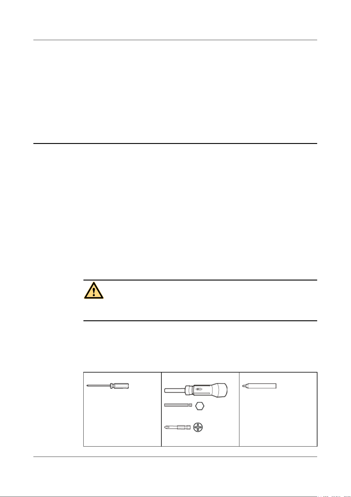
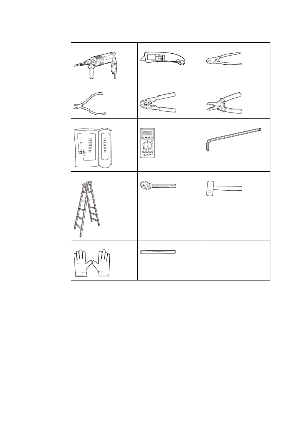
Tool Preparation
To install indoor APs, prepare tools listed in Table 2-1.
Table 2-1 Tools
Phillips screwdriver
slipping.
CAUTION
Torque screwdriver
Marker
3mm/5mm
(M3-M6)
Issue 12 (2015-08-05) Huawei Proprietary and Confidential
Copyright © Huawei Technologies Co., Ltd.
14
Page 22
AP3x10xN&5x10xN&5x30xN&6x10xN&7x10xN
Hardware Installation and Maintenance Guide
Hammer drill (φ6) Utility knife Cable cutter
Diagonal pliers RJ45 crimping tool Wire stripper
Network cable tester Multimeter Inner hexagon wrench
2 AP Installation
Ladder Adjustable wrench Rubber mallet
ESD gloves Level
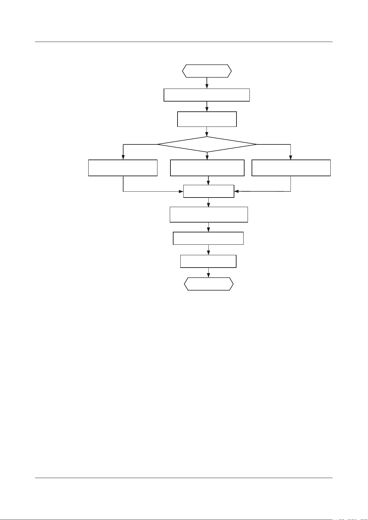
2.2 Installation Flowchart
The following figure shows the process for installing an indoor AP.
–
Issue 12 (2015-08-05) Huawei Proprietary and Confidential
Copyright © Huawei Technologies Co., Ltd.
15
Page 23
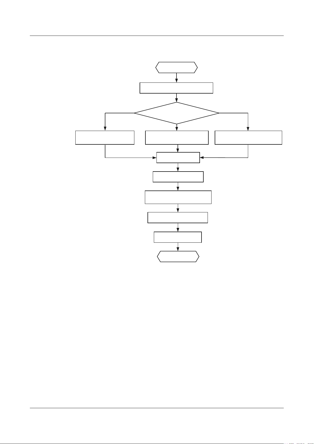
Determine the
installation location
Start
Check before installation
Install the AP
Connect the cable
Connect the security lock
to the lock hole
Power on the AP
Check after installation
End
Fix the wall-mounting
bracket to a T-rail
Fix the wall-mounting
bracket against the wall
Fix the wall-mounting
bracket against the ceiling
To a T-rail
Against the ceiling
Against the wall
AP3x10xN&5x10xN&5x30xN&6x10xN&7x10xN
Hardware Installation and Maintenance Guide 2 AP Installation
Figure 2-1 Installation flowchart of the AP3010DN-AGN, AP5010DN-AGN, AP5010SN-GN,
AP6010DN-AGN, AP6010SN-GN, AP6310SN-GN, AP7110SN-GN and AP7110DN-AGN
Issue 12 (2015-08-05) Huawei Proprietary and Confidential
Copyright © Huawei Technologies Co., Ltd.
16
Page 24
Connect the cable
Start
Check before installation
Install the AP
Determine the
installation location
Connect the security lock
to the lock hole
Power on the AP
Check after installation
End
Fix the wall-mounting
bracket to a T-rail
Fix the wall-mounting
bracket against the wall
Fix the wall-mounting
bracket against the ceiling
To a T-rail
Against the ceiling
Against the wall
AP3x10xN&5x10xN&5x30xN&6x10xN&7x10xN
Hardware Installation and Maintenance Guide
Figure 2-2 Installation flowchart of the AP5030DN and AP5130DN
2 AP Installation
2.3 Unpacking the Equipment
Before unpacking the carton, ensure that the packing carton is intact and not damaged or soaked.
Stop unpacking if the equipment is rusted or soggy. Then, investigate causes and contact the
supplier.
After unpacking, check items in the carton against the packing list. If any item is missing, contact
the supplier or agent.
Usually, the packing list contains the following items.
l AP device
l Power adapter (optional)
l Sheet metal mounting bracket
l 2.4 GHz antenna
l 5 GHz antenna
1
1
l Dual-band antenna port
l Expansion screws
4
2
Issue 12 (2015-08-05) Huawei Proprietary and Confidential
Copyright © Huawei Technologies Co., Ltd.
17
Page 25
AP3x10xN&5x10xN&5x30xN&6x10xN&7x10xN
Hardware Installation and Maintenance Guide
2 AP Installation
l OT terminal
3
l Quick Start Guide
l Warranty card
l Qualification Card
l MAC address label
l SN label
NOTE
If the AT needs to be powered by an AC power supply, a PoE adapter must be independently purchased.
Pay attention to the following:
1. Three 2.4 GHz antennas and three 5 GHz antennas are contained in the AP7110DN-AGN
carton, and three 2.4 GHz antennas are contained in the AP7110SN-GN carton. Cartons of
other models do not contain these two types of antennas.
2. Only the AP5130DN carton contains three dual-band antennas.
3. Only the AP6310SN-GN and AP7110 series have OT terminals delivered.
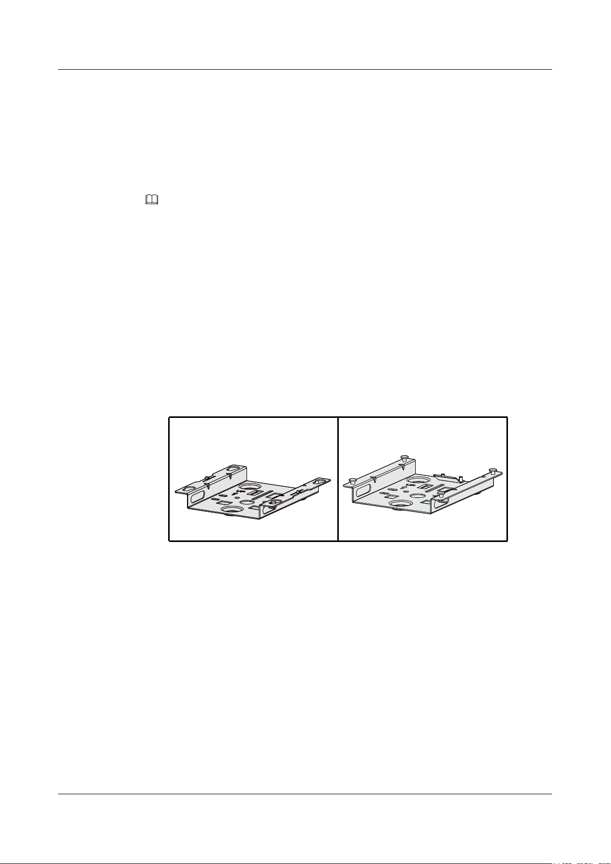
4. Currently, two types of sheet metal mounting brackets are available: sheet metal mounting
bracket for the AP5030DN and AP5130DN, which has four mounting holes (see the left
figure in Figure 2-3), and sheet metal mounting bracket for other indoor AP models, which
has four mounting screws (see the right figure in Figure 2-3).
Figure 2-3 Sheet metal mounting brackets
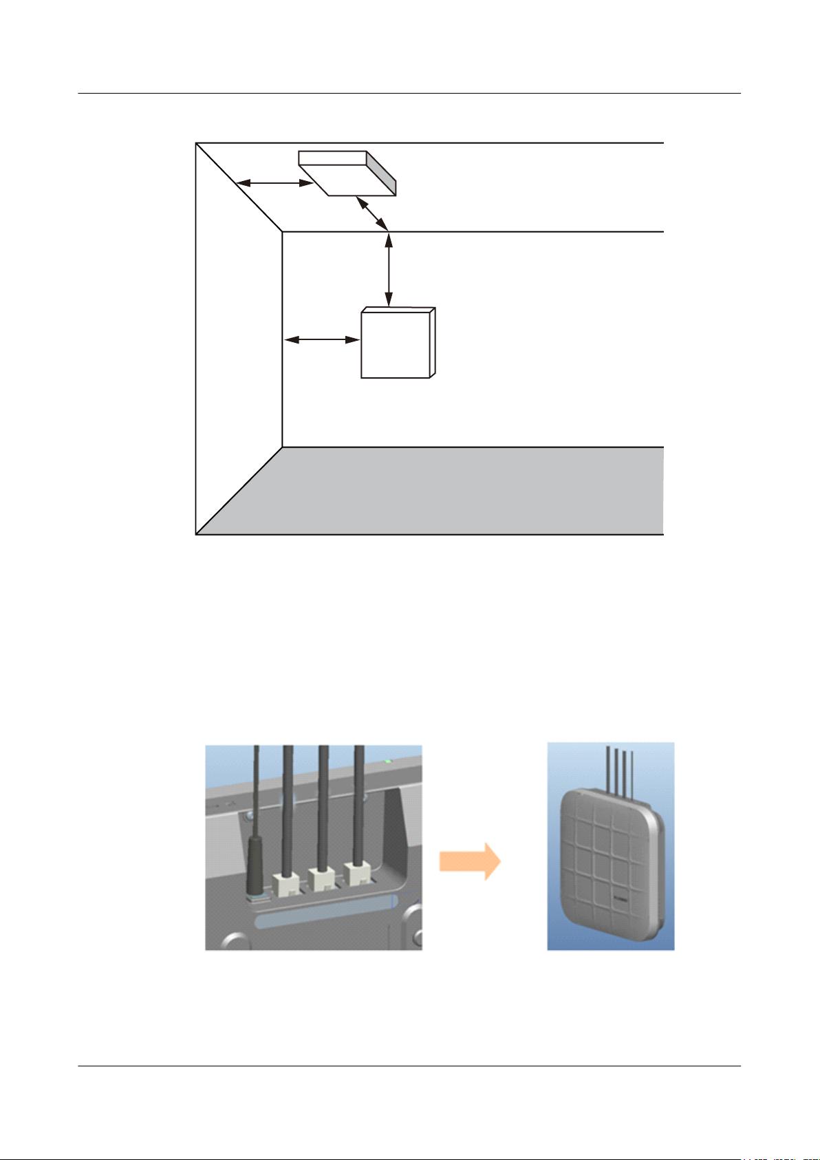
2.4 Determining the Installation Position
When determining the AP installation position, comply with the following rules:
l Try to reduce the number of obstacles, such as walls, between the AP and user terminals.
l Install the AP away from electronic devices that can cause radio interference, such as the
microwave oven.
l Install the AP in a hidden position that does not affect daily lives and work of residents.
l Install the AP in a site that is free from leaking or dripping water, heavy dew, and humidity,
and take protective measures to prevent water from flowing into the equipment along the
cable.
Indoor APs are usually mounted on a wall or ceiling using sheet metal mounting brackets. The
installation position is determined by the site survey. There must be at least 200 mm clearance
between the cabling end of the AP and the wall. Figure 2-4 shows space requirements.
Issue 12 (2015-08-05) Huawei Proprietary and Confidential
Copyright © Huawei Technologies Co., Ltd.
18
Page 26
≥200mm
≥200mm
≥200mm
≥200mm
Floor
Celling
Wall
AP3x10xN&5x10xN&5x30xN&6x10xN&7x10xN
Hardware Installation and Maintenance Guide 2 AP Installation
Figure 2-4 Mounting an AP
2.5 Installing the AP
All cables of the AP5030DN and AP5130DN, including network cables, power supply cables,
and console cables are routed towards the same direction. Before installing an AP on the
mounting bracket, connect cables to the AP first. Figure 2-5 shows cable deployment and AP
installation.
Figure 2-5 Cable deployment and AP installation
Issue 12 (2015-08-05) Huawei Proprietary and Confidential
Copyright © Huawei Technologies Co., Ltd.
19
Page 27
59mm
85mm
UP UP
25mm~30mm
1 2
AP3x10xN&5x10xN&5x30xN&6x10xN&7x10xN
Hardware Installation and Maintenance Guide
NOTE
l The AP5030DN and AP5130DN must have cables connected first before installation. Except the two
models, the procedures for installing the other models of indoor APs are the same unless otherwise
stated. The following figures use the AP7110DN-AGN as an example.
l Remove the protective film on the AP surface before installation to prevent electrostatic discharge.
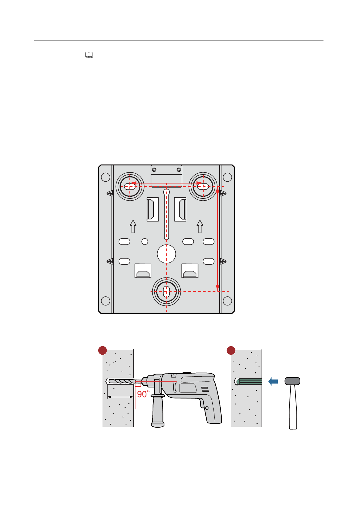
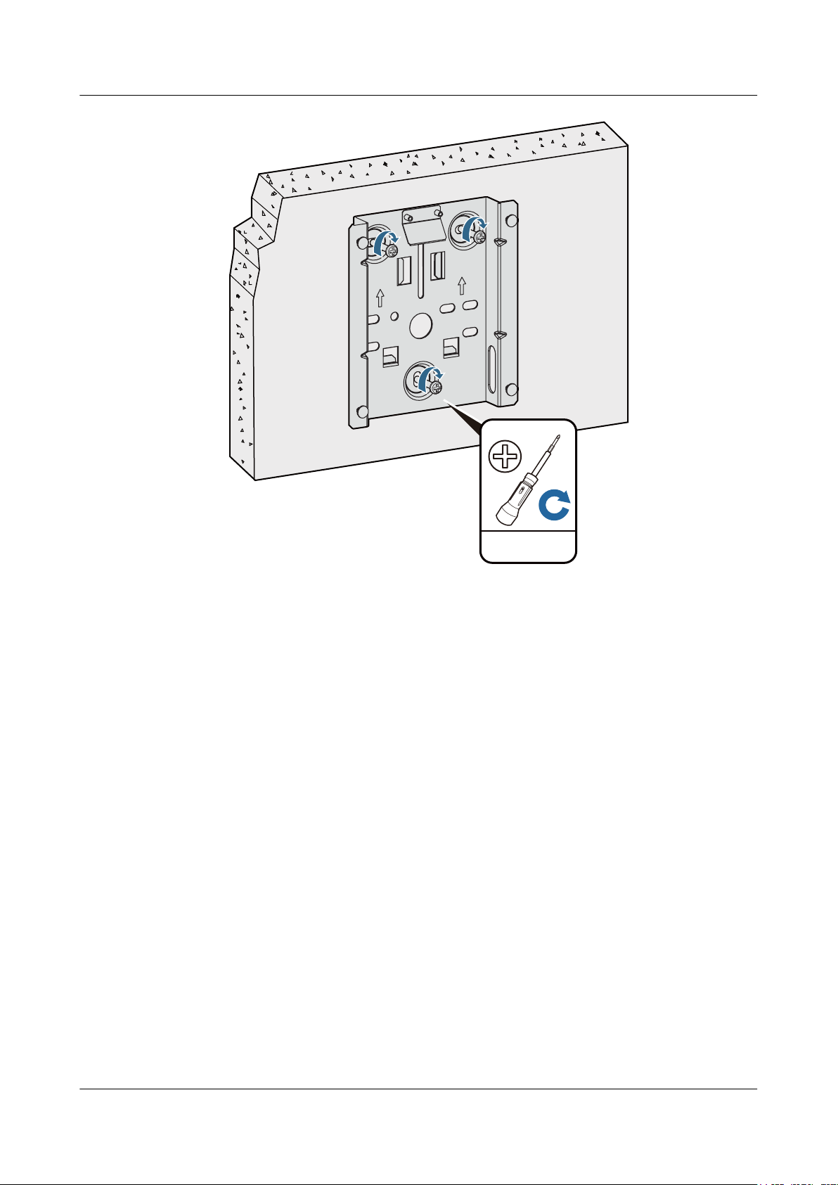
2.5.1 Wall Mounting
Mounting APs on a wall requires sheet metal mounting brackets and expansion screws. The
procedures are as follows:
1. Fix the mounting bracket to the wall, adjust the installation position, and use the marker to
mark the drilling positions where expansion screws are installed.
2 AP Installation
2. Use a 6 mm drill bit to drill 25 mm to 30 mm deep holes in the drilling positions. Hammer
the expansion tubes into the holes until the expansion tubes are completely embedded into
the wall.
3. Fix the mounting bracket to the wall and use the Phillips screwdriver to fasten three
expansion screws into the expansion tubes.
Issue 12 (2015-08-05) Huawei Proprietary and Confidential
Copyright © Huawei Technologies Co., Ltd.
20
Page 28
UP
UP
0.3N•m
ST3.5
AP3x10xN&5x10xN&5x30xN&6x10xN&7x10xN
Hardware Installation and Maintenance Guide 2 AP Installation
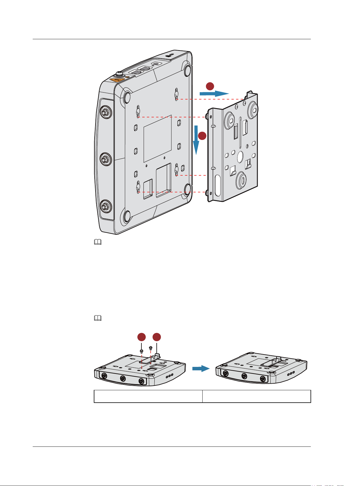
4. Align the mounting holes at the rear of the AP with the mounting screws on the mounting
bracket and hang the AP on the bracket. Press the AP downwards to secure the AP on the
wall.
Issue 12 (2015-08-05) Huawei Proprietary and Confidential
Copyright © Huawei Technologies Co., Ltd.
21
Page 29
1
2
5G
5G
5G
LABEL
5G
5G
5G
LABEL
SYS
Link
Wireless
5G
5G
5G
LABEL
SYS
Link
Wireless
1 2
AP3x10xN&5x10xN&5x30xN&6x10xN&7x10xN
Hardware Installation and Maintenance Guide
2 AP Installation
The AP5030DN and AP5130DN use a different type of sheet metal mounting bracket than other APs.
When installing an AP5030DN or AP5130DN, align the mounting screws at the rear of the AP with the
mounting holes on the sheet metal mounting bracket and then press the AP downwards to secure the AP
on the bracket.
2.5.2 Ceiling Mounting
1. Fix a locking clip at the rear of the AP with two M3x6 screws. The locking clip prevents
the AP hung on the mounting bracket from swaying.
Only the AP6310SN-GN and AP7110 series require the locking clip during their installation.
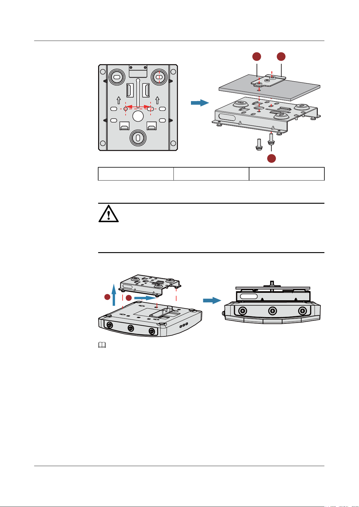
2. Remove a ceiling tile, determine locations of mounting holes based on the distance between
two installation holes on the mounting bracket, use a hammer drill to drill holes on the
ceiling tile, and fix the mounting bracket to the ceiling tile.
NOTE
NOTE
1. M3x6 screw
2. Locking clip
Issue 12 (2015-08-05) Huawei Proprietary and Confidential
Copyright © Huawei Technologies Co., Ltd.
22
Page 30
35mm
UP UP
21
3
5G
5G
5G
LABEL
SYS
Link
Wireless
5G5G5G
2
1
AP3x10xN&5x10xN&5x30xN&6x10xN&7x10xN
Hardware Installation and Maintenance Guide
1. Ceiling tile 2. Adjustable buckle 3. M4x30 screw
2 AP Installation
The screws provided for ceiling-mounting of APs are 30 mm long and can be used to fix
an AP on a ceiling not thicker than 15 mm. To install APs on thicker ceilings, you need to
purchase longer screws.
3. Hang the AP on the mounting screws by aligning the mounting holes at the rear of the AP
with the mounting screws on the bracket and push the AP horizontally to secure the AP.
NOTE
l Ensure that the AP is correctly installed on the mounting bracket and there must be 200 mm space
above and around the AP for maintenance.
l The AP5030DN and AP5130DN use a different type of sheet metal mounting bracket than other APs.
When installing an AP5030DN or AP5130DN, align the mounting screws at the rear of the AP with
the mounting holes on the sheet metal mounting bracket and then press the AP downwards to secure
the AP on the bracket.
2.5.3 T-rail Mounting
NOTICE
Issue 12 (2015-08-05) Huawei Proprietary and Confidential
1. Fix a locking clip at the rear of the AP with two M3x6 screws. For installation methods,
see step 1 in Ceiling Mounting.
Copyright © Huawei Technologies Co., Ltd.
23
Page 31

2
1
3
5G5G5G
5G
5G
5G
LABEL
SYS
Link
Wireless
2
1
AP3x10xN&5x10xN&5x30xN&6x10xN&7x10xN
Hardware Installation and Maintenance Guide
NOTE
Only the AP6310SN-GN and AP7110 series require the locking clip during their installation.
2. Remove two ceiling tiles around the T-rail, use screws to fix the adjustable buckle to the
mounting bracket, hook the adjustable buckle to the T-rail, and secure the screw on the
adjustable buckle to fasten the mounting bracket and T-rail.
1. T-rail 2. Adjustable buckle 3. M3x6 screws
2 AP Installation
3. Align the mounting holes at the rear of the AP with the mounting screws on the sheet metal
mounting bracket and secure the AP on the bracket.
NOTE
l Ensure that the AP is correctly installed on the mounting bracket and there must be 200 mm space
above and around the AP for maintenance.
l The AP5030DN and AP5130DN use a different type of sheet metal mounting bracket than other APs.
When installing an AP5030DN or AP5130DN, align the mounting screws at the rear of the AP with
the mounting holes on the sheet metal mounting bracket and then press the AP downwards to secure
the AP on the bracket.
2.5.4 Removing an AP
To remove an AP, push the metal reed upward with a screwdriver and use the other hand to pull
the AP horizontally (See Figure 2-6).
Issue 12 (2015-08-05) Huawei Proprietary and Confidential
NOTE
Only the AP6310SN-GN and AP7110 series require the locking clip during their installation. Therefore, the
method of removing an AP by pushing the metal reed upward applies only to the AP6310SN-GN and AP7010
series.
Copyright © Huawei Technologies Co., Ltd.
24
Page 32

5G
5G
5G
Wireless
Link
SYS
metal sheet
2
1
6 5
ConsoleETH/PoEDefaultDC 12V
AP3x10xN&5x10xN&5x30xN&6x10xN&7x10xN
Hardware Installation and Maintenance Guide 2 AP Installation
Figure 2-6 Removing an AP
2.6 Connecting Cables
Figures in Table 2-2 show the appearance of indoor APs.
Table 2-2 Appearance of indoor APs (front view)
Product Model Appearance
AP3010DN-AGN
AP5010DN-AGN
AP5010SN-GN
AP6010DN-AGN
AP6010SN-GN
Issue 12 (2015-08-05) Huawei Proprietary and Confidential
Copyright © Huawei Technologies Co., Ltd.
25
Page 33

5 6
Console GE1 GE0/PoE DC 12V
3
5 6
Console GE1 GE0/PoE DC 12V
2.4G
Console ETH/PoE Default DC 12V
2 5 46
AP3x10xN&5x10xN&5x30xN&6x10xN&7x10xN
Hardware Installation and Maintenance Guide 2 AP Installation
Product Model Appearance
AP5030DN
AP5130DN
AP6310SN-GN
Issue 12 (2015-08-05) Huawei Proprietary and Confidential
Copyright © Huawei Technologies Co., Ltd.
26
Page 34

1 5 6 24
Console ETH/PoE Default DC 12V
Console ETH/PoE DC 12VDefault
4 5 6 2
AP3x10xN&5x10xN&5x30xN&6x10xN&7x10xN
Hardware Installation and Maintenance Guide 2 AP Installation
Product Model Appearance
AP7110DN-AGN
AP7110SN-GN
Table 2-3 describes cable connections of indoor APs.
Table 2-3 Cable connections of indoor APs
No. Cable Description
1 5 GHz antenna cable Connects a 5 GHz antenna to the AP to send
and receive service signals.
2 2.4 GHz antenna
cable
Connects a 2.4 GHz antenna to the AP to send
and receive service signals.
3 Dual-band antenna Connects a dual-band antenna to the AP to
send and receive service signals.
4 Ground cable Grounds the AP. The M4 connector of the
ground cable is connected to the AP and the
M6 connector is connected to the protection
ground.
5 Network cable
l CAT5E cables or cables of a higher grade
are used.
l Ensure that the AP is connected to the
Ethernet using the Ethernet cable that
works properly. If the Ethernet cable is not
working properly, for example, RJ45
connectors are short-circuited, the AP
may fail to be powered on or fail to work.
Before connecting an Ethernet cable to the
AP, use the cable test tool to check
whether the cable is qualified. If the cable
is unqualified, replace it.
Issue 12 (2015-08-05) Huawei Proprietary and Confidential
27
Copyright © Huawei Technologies Co., Ltd.
Page 35

a
b
c
AP3x10xN&5x10xN&5x30xN&6x10xN&7x10xN
Hardware Installation and Maintenance Guide
No. Cable Description
2 AP Installation
6 DC power adapter
l The AP supports the PoE power supply
and DC power supply.
l To connect the AP to a DC power source,
use the power adapter delivered with the
AP; otherwise, the AP maybe damaged.
NOTE
l Different power adapters are delivered with indoor AP products according to standards in the countries or
regions where the AP products are delivered. These countries and regions are identified by the barcode on
an AP's nameplate, including: EU (Europe), UK (United Kingdom), CN (China), AU (Australia), US (United
States), and USA (the AP is sold only in the U.S).
l The AP products sold in the U.S have a fixed country code US, and the country code change function is
disabled.
l When PoE and power adapter power supplies are available, the devices are preferentially powered by the
power adapter.
Pay attention to the following points when installing antennas
l Antennas of the AP6310SN-GN, AP7110DN-AGN, AP7110SN-GN, and AP5130DN
must comply with local laws and regulations.
l Antennas need to be installed by qualified personnel. An AP can only use the antennas
delivered with it.
l You need to connect external antennas to the AP7110 series, AP6310SN, and AP5130DN.
Exercise caution when bending the antennas. Misoperation may hurt your hands. Adjust
the antennas according to signal coverage.
When connecting to RF cables, the requirements of bend radius are: RG-8U RF cable: >
150 mm; 1/2" RF cable: > 50 mm; 7/8" RF cable: > 250 mm. One inch (1") equals 25.4
mm.
l When replacing WA633SNs with AP6310SN-GNs, you need to convert SMA connectors
to Type N connectors (see Figure a and Figure b). You can also make new feeder lines
matching the connectors of the AP6310SN-GNs (see Figure c).
l When the RF connector of an AP becomes loose, tighten it with a maximum torque of 13
N•m.
Pay attention to the following points when installing network cables
l Before connecting an Ethernet cable to the AP, use the cable test tool to check whether the
cable is qualified. If the cable is unqualified, replace it.
Issue 12 (2015-08-05) Huawei Proprietary and Confidential
Copyright © Huawei Technologies Co., Ltd.
28
Page 36

2.4G
2.4G
2.4G
Lock hole
Security lock
AP3x10xN&5x10xN&5x30xN&6x10xN&7x10xN
Hardware Installation and Maintenance Guide 2 AP Installation
l Do not connect the service network cable to the console port. Otherwise, the AP may be
damaged when the PoE power supply is used.
l Use standard RJ45 connectors on network cables for the AP5010 series.
l Before removing network cables or power cables from an AP5030DN or AP5130DN,
remove the AP from the mounting bracket first to prevent damage to the network cables or
power cables.
l The cable cannot exceed 100 meters.
2.7 Installing the Security Lock
There is a security slot on the AP. You can lock the AP to an immovable object to prevent the
AP against theft. The detailed procedures are as follows:
1. Fasten the cable of the security lock to an immovable object around.
2. Insert the security lock into the security slot and lock it.
NOTE
You need to purchase the security lock separately.
2.8 Checking the AP After Installation
Table 2-4 shows the items to be checked after AP installation is complete.
Table 2-4 AP installation checklist
No. Check Item
1 The AP is installed by strictly following the design draft. The installation
position meets space requirements, with maintenance space reserved.
2 The AP is securely installed.
3 The power cables and PGND cables are intact and not spliced.
4 Terminals of the power cables and PGND cables are welded or cramped
firmly.
5 All power cables or PGND cables are not short-circuited or reversely
connected and must be intact with no damage.
Issue 12 (2015-08-05) Huawei Proprietary and Confidential
Copyright © Huawei Technologies Co., Ltd.
29
Page 37

AP3x10xN&5x10xN&5x30xN&6x10xN&7x10xN
Hardware Installation and Maintenance Guide 2 AP Installation
No. Check Item
6 The power cables and ground cables are separated from other cables and
bundled separately.
7 The working ground, protection ground, and surge protection ground share
the same group of ground bars.
8 Connectors of signal cables are complete, intact, and tightly connected.
The signal cables are not damaged or broken.
9 Labels on cables, feeders, or jumpers are clear and correct.
2.9 Powering on the AP
Indoor APs support the DC power supply and PoE power supply. You can select the power
supply mode as required.
Checking Before Power-on
After the AP installation is complete, check the following items before powering on the AP:
l The AP is correctly connected to the power adapter if it uses the DC power supply.
l The PoE power supply device is well grounded if the AP uses the PoE power supply.
NOTE
l The AP6010DN-AGN, AP6010SN-GN, and AP6310SN-GN cannot use the PoE power supply and DC
power supply simultaneously.
l Do not frequently power on and off an AP.
Indicator Status
You can check the power-on status by observing indicators on the AP. For details, see 1.2
Indicator Description.
Issue 12 (2015-08-05) Huawei Proprietary and Confidential
Copyright © Huawei Technologies Co., Ltd.
30
Page 38

AP3x10xN&5x10xN&5x30xN&6x10xN&7x10xN
Hardware Installation and Maintenance Guide
3 Logging In to the AP
3 Logging In to the AP
3.1 Logging In to the AP Through the Console Port
This section describes how to log in to the AP through the console port. After logging in to the
AP, you can configure the AP using commands.
1. Connect a PC to the AP using a console cable. Connect the RJ45 connector to the console
port of the AP and the DB9 connector to the serial port of a PC.
NOTE
If your PC's operating system provides terminal simulation software (like HyperTerminal in
Windows 2000/XP), you do not need to install additional terminal simulation software. If the PC
runs on an operating system without terminal simulation software (like Windows 7), install thirdparty terminal simulation software on the PC by referring to user manual or online help.
2. Start the terminal simulation software, create a connection, select a serial port, and set
communication parameters as follows.
l Bits per second (B): 9600
l Data bits (B): 8
l Parity (P): None
l Stop bits (S): 1
l Flow control (F): None
3. Press Enter until the command line prompt of the user view, such as <Huawei>, is
displayed. Then, you enter the user configuration interface. You can run commands to
configure the AP. Enter a question mark (?) whenever you need help.
3.2 Logging In to the AP Using STelnet
This section describes how to log in to the AP using STelnet. After logging in to the AP, you
can configure the AP using commands.
Before logging in to the device through STelnet, complete the following tasks:
l Starting the device properly
l Preparing network cables used to connect device interfaces.
Issue 12 (2015-08-05) Huawei Proprietary and Confidential
Copyright © Huawei Technologies Co., Ltd.
31
Page 39

AP3x10xN&5x10xN&5x30xN&6x10xN&7x10xN
Hardware Installation and Maintenance Guide
l Configuring the PC's IP address and subnet mask. The IP address must be on the network
segment 169.254.0.0/16 but cannot be 169.254.1.1. 169.254.1.100 is recommended. The
subnet mask is 255.255.0.0.
NOTE
l Ensuring that the IP address 169.254.1.1 and subnet mask 255.255.0.0 have been configured on VLANIF
1 of the device before the delivery, and GE0/0/0 has been added to VLAN 1 by default.
l Before the device is delivered, the STelnet service has been configured on the device. The STelnet interface
number is 22, and the default user name and password are respectively admin and admin@huawei.com.
Use the SSH client software to log in to the device through STelnet from a terminal. The
third-party software PuTTY is used as an example here.
1. After the device is powered on, connect the PC's network interface to GE0/0/0 of the device
using network cables.
NOTE
Ping 169.254.1.1 from the PC to check whether the device can be pinged successfully. If the ping
operation fails, check whether the PC's IP address is correct or replace the network cable.
2. Use the PuTTY software to log in to the device, enter the device IP address, and select the
SSH protocol type.
3 Logging In to the AP
Figure 3-1 PuTTY Configuration page
Issue 12 (2015-08-05) Huawei Proprietary and Confidential
Copyright © Huawei Technologies Co., Ltd.
32
Page 40

AP3x10xN&5x10xN&5x30xN&6x10xN&7x10xN
Hardware Installation and Maintenance Guide
3. Click Open. Enter the user name and password at the prompt, and press Enter. You have
logged in to the device. (The following information is only for reference.)
login as: admin
admin@169.254.1.1's password:
<Huawei>
NOTE
It is recommended that you change the initial user name and password after login.
3.3 Logging In to the AP Using Telnet
This section describes how to log in to the AP using Telnet. After logging in to the AP, you can
configure the AP using commands.
NOTE
l In V200R005C00 and later versions, upon factory delivery, the Telnet server is disabled. Before
connecting to the device through Telnet from a user terminal, make sure that the Telnet service is
enabled on the device by the STelnet service.
l The Telnet protocol poses a security risk, and therefore the STelnet protocol is recommended.
3 Logging In to the AP
1. Connect a PC to the ETH/PoE interface of the AP using a network cable.
2. Configure a static IP address for the PC. The IP address must be in the same network
segment as the AP's IP address. After completing the configuration, ping the AP's IP address
from the PC. If the ping operation succeeds, the connection is set up successfully. If the
ping operation fails, check whether the network cable is faulty.
NOTE
l In V200R002C00 and earlier versions, the IP address 192.168.0.1 and subnet mask 255.255.255.0
have been configured on VLANIF 1 of the AP before the delivery, and GE0/0/1 has been added to
VLAN 1 by default.
l In V200R003C00 and later versions, the IP address 169.254.1.1 and subnet mask 255.255.0.0 have
been configured on VLANIF 1 of the AP before the delivery, and GE0/0/1 has been added to VLAN
1 by default.
l If the AP working in Fit AP mode is online on the AC, the DHCP server automatically assigns an IP
address to the AP. You can remotely log in to the AC on a local terminal and run the following
command to check the AP's IP address:
l For V200R005C30 and earlier versions: display ap-run-info id ap-id
l For V200R006C00: display ap run-info ap-name ap-name
3. Enter the command line interface on the PC. For example, in Windows XP, choose Start
> Run and enter cmd in the displayed dialog box.
4. Use Telnet to log in to the AP.
5. Enter the default user name admin. The initial password is admin in V200R002C00 and
earlire versions and is admin@huawei.com in V200R003C00 and later versions. If the
user view is displayed, you have logged in successfully. You are advised to change the user
name and password on your first login.
Issue 12 (2015-08-05) Huawei Proprietary and Confidential
Copyright © Huawei Technologies Co., Ltd.
33
Page 41

AP3x10xN&5x10xN&5x30xN&6x10xN&7x10xN
Hardware Installation and Maintenance Guide
NOTE
You can run the quit command to exit from the Telnet window. When the system fails to exit from the
Telnet window:
l If you logged in to the AP from an AC or a switch, press Ctrl+T to return to the AC or switch view.
This operation does not affect AP services.
l If you logged in to the AP from a PC, directly close the Telnet window. This operation does not affect
AP services.
3.4 Logging In to the AP Using a Web Client
Pre-configuration Tasks
Before configuring users to log in to the AP using HTTP, complete the following task:
Configure reachable routes between the terminal and the AP.
NOTE
l The web management system is enabled on the AP before delivery. The default IP address of the web
management system is 169.254.1.1 and the mask is 255.255.0.0. The web management system provides
a default user account, with the user name admin and password admin@huawei.com. You are advised
to change the user name and password on your first login. Assign your PC an IP address on the same
network segment as the default IP address of the web management system, and connect the PC to the
GE interface. Start the web browser on the PC and visit http://169.254.1.1 to log in to the web
management system.
l You can only log in to the FAT AP using the web platform.
3 Logging In to the AP
Procedure
Step 1 Open a web browser on a PC, and enter the management address in the format of http://
Step 2 Click Login or press Enter. The web system home page is displayed. You can manage and
169.254.1.1 in the address bar. Ensure that the PC and AC can communicate with each other.
Then press Enter. Set the language, user name, and password. The HTTPS login URL is
displayed in the address box indicating that the system has gone to the HTTPS login page.
NOTE
You can also enter https://IP address in the address box to log in to the AP using HTTPS. HTTPS ensures
security of login information during login and security of data exchanged during subsequent operations.
maintain the equipment. For details, see the Huawei Wireless Access Points Web-based
Configuration.
----End
Issue 12 (2015-08-05) Huawei Proprietary and Confidential
Copyright © Huawei Technologies Co., Ltd.
34
Page 42

AP3x10xN&5x10xN&5x30xN&6x10xN&7x10xN
Hardware Installation and Maintenance Guide
4 Hardware Failures
4.1 A Device Fails to Be Powered On
Fault Description
4 Hardware Failures
The SYS indicator of a device is off.
Possible Causes
Power Supply Mode Possible Cause
Power supply using a power module
PoE power supply
l The power switch on the device is turned
off.
l The power cable is not securely connected
to the device.
l The power supply unit has failed.
– If the device connects to an external
power source, its power adapter may
fail.
– If the device has a built-in power
supply, the device itself may be faulty.
l The power sourcing equipment does not
support the PoE function or is faulty.
l The power sourcing equipment is
incorrectly configured (the PoE function
is disabled or the power-off time range is
improperly set).
l The line is faulty (the network cable or
distribution frame is damaged).
l The AP is faulty.
Issue 12 (2015-08-05) Huawei Proprietary and Confidential
Copyright © Huawei Technologies Co., Ltd.
35
Page 43

AP3x10xN&5x10xN&5x30xN&6x10xN&7x10xN
Hardware Installation and Maintenance Guide
Troubleshooting Procedure
Power Supply Mode Troubleshooting Procedure
Power supply using a power module 1. Check that the power switch is on.
4 Hardware Failures
2. Check that the power cable is securely
connected to the device.
3. Check whether the power supply is
normal.
Replace the power adapter with a normal
one. If the device is powered on, the
original power adapter is faulty. Contact
Huawei technical support or Huawei
agent and ask them to replace the power
adapter.
4. If the device still cannot be powered on,
the device itself is faulty. Contact Huawei
technical support or Huawei agent and ask
them to replace the device.
PoE power supply
1. Check whether the power sourcing
equipment supports PoE or is faulty.
2. Check whether the configuration on the
power sourcing equipment causes PoE
power supply errors, such as the PoE
function is disabled or the power-off time
range is incorrectly set.
3. Check whether the network cable or
distribution frame is faulty.
4. If the device still cannot be powered on,
the device itself is faulty. Contact Huawei
technical support engineers or Huawei
agent and ask them to replace the device.
4.2 An Optical Interface Cannot Turn Up
Fault Description
After an optical interface is connected to a remote device through an optical fiber, its LINK
indicator is off.
Possible Causes
l The optical fiber is faulty.
l The optical module on the optical interface cannot meet the requirements.
Issue 12 (2015-08-05) Huawei Proprietary and Confidential
Copyright © Huawei Technologies Co., Ltd.
36
Page 44

AP3x10xN&5x10xN&5x30xN&6x10xN&7x10xN
Hardware Installation and Maintenance Guide 4 Hardware Failures
Troubleshooting Procedure
1. Replace the optical fiber and optical module and check whether the optical interface can
turn Up. Ensure that the optical module meets the following requirements.
2. Determine optical module attributes.
l The optical module has passed Huawei certification.
l The transmission speed of the optical module is the same as the interface speed.
l The wavelength of the optical module is the same as that of the remote optical module.
l The transmission distance of the optical module is suitable for the actual distance
between the two devices.
NOTE
l The transmission distance of an optical module is 10 km, 15 km, 20 km, 40 km, or 80 km.
The optical modules with a longer transmission distance have a higher transmit power. If an
optical module with a long transmission distance is used for short-distance transmission, the
optical interface cannot turn Up because the transmit power is too high. The high transmit
power may even burn the receiver of the remote optical module. To reduce the transmit power
in this situation, use an optical attenuator between the optical module and optical fiber.
l Optical modules with different speeds are available, for example, 155 Mbit/s, 622 Mbit/s,
and 1.25 Gbit/s. It is recommended that you use an optical module with the same speed as
the optical interface to ensure efficient optical transmission.
3. If the interface remains Down, contact Huawei technical support.
Issue 12 (2015-08-05) Huawei Proprietary and Confidential
Copyright © Huawei Technologies Co., Ltd.
37
Page 45

AP3x10xN&5x10xN&5x30xN&6x10xN&7x10xN
Hardware Installation and Maintenance Guide
5 Appendix
5.1 On-site Cable Assembly and Installation
5 Appendix
5.1.1 Cable Assembly Precautions
Checking the Appearance of Cables
l If the cable jacket or insulation is visibly dirty, clean it before assembly.
l If the jacket or insulation of a cable has visible damage, irreparable scuffing, or other
defects, do not use the cable.
l If the shield layer of a cable is damaged, do not use the cable.
l If the cable jacket or insulation cracks after the cable is bent or twisted, discard this cable
and check whether other cables have the same problem. If other cables have the same
problem, replace these cables.
Checking the Appearance of Connectors
l Do not use connectors with visible defects, damage, rust or scuffing.
l Do not use connectors if their shells or pins have exposed part or uneven plating, or their
pins are lost, broken, or bent.
l Do not use connectors that have dirt on their pins or in their jacks or if there are conductors
between pins or between pins and the shell.
Precautions for Assembly
l Use dedicated tools or tools delivered by Huawei and follow the methods given here during
assembly.
l Hold terminals of cables instead of pulling the cables themselves when installing or
removing cable components.
l Take the following precautions when cutting or stripping cables:
– Make cables slightly longer than necessary.
Issue 12 (2015-08-05) Huawei Proprietary and Confidential
Copyright © Huawei Technologies Co., Ltd.
38
Page 46

AP3x10xN&5x10xN&5x30xN&6x10xN&7x10xN
Hardware Installation and Maintenance Guide
– Coil cables longer than 2 m (6.56 ft) after cutting. Bind and fasten the coils using
bundling ropes. The inner diameters of the coils should be larger than 20 times the outer
diameters of the cables.
– When stripping the jackets of cables, avoid damaging the shield layers (braid or
aluminum foil), insulation, core conductors, and other jackets that do not need to be
stripped.
– After assembling cables, cut all visible cross sections of jackets to ensure that the cross
sections are arranged neatly.
– Do not touch the core conductors of cables with your hands. Terminate exposed
conductors in a timely way after stripping off insulation so that the surface of the
conductors does not become oxidized.
l Take the following precautions when crimping and connecting cables or connectors:
– The terminals and conductors should be connected tightly after they are crimped. They
should not be moved or turned.
– Cut all the exposed copper wires.
– Try to avoid a second crimping of sleeves.
– Keep all the conductors clean and aligned.
5 Appendix
NOTE
The connectors, cables, and tools provided by different vendors may be different. The figures in this
document are for your reference only.
5.1.2 Assembling Power Cables
Assembling the OT Terminal and Power Cable
Context
Figure 5-1 shows the components of an OT terminal and a power cable.
Figure 5-1 Components of an OT terminal and a power cable
A. Heat-shrinkable tubing
B. Bare crimping terminal C. Insulation D. Conductor
Issue 12 (2015-08-05) Huawei Proprietary and Confidential
Copyright © Huawei Technologies Co., Ltd.
39
Page 47

AP3x10xN&5x10xN&5x30xN&6x10xN&7x10xN
Hardware Installation and Maintenance Guide
Procedure
Step 1 Based on the cross-sectional area of the cable conductor, strip a length of insulation coating C
to expose the conductor D of length L1, as shown in Figure 5-2. The recommended values of
L1 are listed in Table 5-1.
Figure 5-2 Stripping a power cable (OT terminal)
5 Appendix
NOTICE
l When you strip a power cable, do not damage the conductor of the cable.
l If the bare crimping terminal is not provided by Huawei, the value of L1 is 1 mm (0.04 in.)
to 2 mm (0.08 in.) greater than the value of L.
Table 5-1 Mapping between the cross-sectional area of the conductor and the value of L1
CrossSectional Area
of Conductor
(mm2(in.2))
1 (0.002) 7 (0.28) 10 (0.015) 11 (0.43)
1.5 (0.002) 7 (0.28) 16 (0.025) 13 (0.51)
2.5 (0.004) 7 (0.28) 25 (0.039) 14 (0.55)
Value of L1 (mm
(in.))
Cross-Sectional
Area of Conductor
(mm2(in.2))
Value of L1 (mm
(in.))
4 (0.006) 8 (0.31) 35 (0.054) 16 (0.63)
6 (0.009) 9 (0.35) 50 (0.077) 16 (0.63)
Issue 12 (2015-08-05) Huawei Proprietary and Confidential
Copyright © Huawei Technologies Co., Ltd.
40
Page 48

AP3x10xN&5x10xN&5x30xN&6x10xN&7x10xN
Hardware Installation and Maintenance Guide 5 Appendix
NOTE
If you are proficient in assembling OT terminals and power cables, you can obtain the value of L1 by
comparing the part to be crimped with the power cable.
Step 2 Put the heat-shrinkable (A) tubing onto the bare crimping terminal, as shown in Figure 5-3.
Figure 5-3 Putting the heat shrink tubing onto the bare crimping terminal
Step 3 Put the OT terminal B onto the exposed conductor, and ensure that the OT terminal is in good
contact with the insulation coating C, as shown in Figure 5-3.
NOTICE
After the conductor is fed into the OT terminal, the protruding part of the conductor, or L2 in
Figure 5-3, must not be longer than 2 mm (0.08 in.).
Step 4 Crimp the joint parts of the bare crimping terminal and the conductor, as shown in Figure 5-4.
NOTE
The shapes of crimped parts may vary with the crimping dies.
Issue 12 (2015-08-05) Huawei Proprietary and Confidential
Copyright © Huawei Technologies Co., Ltd.
41
Page 49

AP3x10xN&5x10xN&5x30xN&6x10xN&7x10xN
Hardware Installation and Maintenance Guide
Figure 5-4 Crimping the joint parts of the bare crimping terminal and the conductor (OT
terminal)
Step 5 Push the heat shrink tubing (A) toward the connector until the tube covers the crimped part, and
then use a heat gun to heat the tube, as shown in Figure 5-5.
5 Appendix
Figure 5-5 Heating the heat shrink tubing (OT terminal)
NOTICE
Stop heating the shrink tubing when the connector is securely locked in the shrink tubing. Do
not heat the shrink tubing too long as this may damage the insulation coating.
----End
Assembling the JG Terminal and Power Cable
Issue 12 (2015-08-05) Huawei Proprietary and Confidential
Copyright © Huawei Technologies Co., Ltd.
42
Page 50

AP3x10xN&5x10xN&5x30xN&6x10xN&7x10xN
Hardware Installation and Maintenance Guide
Context
Figure 5-6 shows the components of a JG terminal and a power cable.
Figure 5-6 Components of a JG terminal and a power cable
A. JG terminal B. Heat-shrinkable tubing C. Insulation layer of a power cable D. Conductor of a power cable
5 Appendix
Procedure
Step 1 Strip a part of the insulation to expose the cable conductor with a length of L, as shown in Figure
5-7. The recommended values of L are listed in Table 5-2.
NOTICE
l When you strip a power cable, do not damage the conductor of the cable.
l If the bare crimping terminal is not provided by Huawei, you can adjust the value of L as
required.
Figure 5-7 Stripping a power cable (JG terminal)
Issue 12 (2015-08-05) Huawei Proprietary and Confidential
Copyright © Huawei Technologies Co., Ltd.
43
Page 51

AP3x10xN&5x10xN&5x30xN&6x10xN&7x10xN
Hardware Installation and Maintenance Guide
Table 5-2 Mapping between the cross-sectional area of the conductor and the value of L
5 Appendix
Cross-Sectional Area of Conductor
Value of L (mm(in.))
(mm2(in.2))
16 (0.025) 13 (0.51)
25 (0.039) 14 (0.55)
35 (0.054) 16 (0.63)
50 (0.077) 16 (0.63)
Step 2 Put the heat shrink tubing onto the bare crimping terminal, as shown in Figure 5-8.
Figure 5-8 Putting the heat shrink tubing onto the bare crimping terminal
Step 3 Put the bare crimping terminal onto the exposed conductor, and ensure that the bare crimping
terminal is in good contact with the insulation of the power cable, as shown in Figure 5-8.
Step 4 Crimp the joint parts of the bare crimping terminal and the conductor, as shown in Figure 5-9.
Figure 5-9 Crimping the joint parts of the bare crimping terminal and the conductor (JG terminal)
Step 5 Push the heat shrink tubing toward the connector until the tube covers the crimped part, and then
use a heat gun to heat the tube, as shown in Figure 5-10.
Issue 12 (2015-08-05) Huawei Proprietary and Confidential
Copyright © Huawei Technologies Co., Ltd.
44
Page 52

AP3x10xN&5x10xN&5x30xN&6x10xN&7x10xN
Hardware Installation and Maintenance Guide
Figure 5-10 Heating the heat shrink tubing (JG terminal)
----End
5 Appendix
Assembling the Cord End Terminal and the Power Cable
Context
Figure 5-11 shows the components of a cord end terminal and a power cable.
Figure 5-11 Components of a cord end terminal and a power cable
A. Cord end terminal
B. Insulation layer of a power cable C. Conductor of a power cable
Procedure
Step 1 Strip a part of the insulation to expose the cable conductor with a length of L1, as shown in
Figure 5-12. The recommended values of L1 are listed in Table 5-3.
Issue 12 (2015-08-05) Huawei Proprietary and Confidential
Copyright © Huawei Technologies Co., Ltd.
45
Page 53

AP3x10xN&5x10xN&5x30xN&6x10xN&7x10xN
Hardware Installation and Maintenance Guide
NOTICE
When you strip a power cable, do not damage the conductor of the cable.
Figure 5-12 Stripping a power cable (cord end terminal)
5 Appendix
Table 5-3 Mapping between the cross-sectional area of the conductor and the value of L1
CrossSectional Area
of Conductor
(mm2(in.2))
1 (0.002) 8 (0.31) 10 (0.015) 15 (0.59)
1.5 (0.002) 10 (0.39) 16 (0.025) 15 (0.59)
2.5 (0.004) 10 (0.39) 25 (0.039) 18 (0.71)
4 (0.006) 12 (0.47) 35 (0.054) 19 (0.75)
6 (0.009) 14 (0.55) 50 (0.077) 26 (1.02)
Step 2 Put the cord end terminal onto the conductor, and ensure that the conductor is aligned with the
edge of the cord end terminal, as shown in Figure 5-13.
Value of L1 (mm
(in.))
Cross-Sectional
Area of Conductor
(mm2(in.2))
Value of L1 (mm
(in.))
NOTICE
After the conductor is fed into the cord end terminal, the protruding part of the conductor must
not be longer than 1 mm (0.04 in.).
Issue 12 (2015-08-05) Huawei Proprietary and Confidential
Copyright © Huawei Technologies Co., Ltd.
46
Page 54

AP3x10xN&5x10xN&5x30xN&6x10xN&7x10xN
Hardware Installation and Maintenance Guide 5 Appendix
Figure 5-13 Putting the cord end terminal onto the conductor
Step 3 Crimp the joint parts of the cord end terminal and the conductor, as shown in Figure 5-14.
Figure 5-14 Crimping the cord end terminal and the conductor
Step 4 Check the maximum width of the tubular crimped terminal. The maximum width of a tubular
crimped terminal is listed in Table 5-4.
Table 5-4 Maximum width of a tubular crimped terminal
Cross-Sectional Area of Tubular
Terminal (mm2(in.2))
Maximum Width of Crimped Terminal
W1 (mm(in.))
0.25 (0.0004) 1 (0.04)
0.5 (0.0008) 1 (0.04)
1.0 (0.0015) 1.5 (0.06)
1.5 (0.0023) 1.5 (0.06)
2.5 (0.0039) 2.4 (0.09)
4 (0.006) 3.1 (0.12)
Issue 12 (2015-08-05) Huawei Proprietary and Confidential
Copyright © Huawei Technologies Co., Ltd.
47
Page 55

AP3x10xN&5x10xN&5x30xN&6x10xN&7x10xN
Hardware Installation and Maintenance Guide
5 Appendix
Cross-Sectional Area of Tubular
Terminal (mm2(in.2))
6 (0.009) 4 (0.16)
10 (0.015) 5.3 (0.21)
16 (0.025) 6 (0.24)
25 (0.039) 8.7 (0.34)
35 (0.054) 10 (0.39)
----End
Maximum Width of Crimped Terminal
W1 (mm(in.))
5.1.3 Assembling Ethernet Cables
Assembling the Shielded RJ45 Connector and Ethernet Cable
Context
Figure 5-15 shows the components of an RJ45 connector and a shielded Ethernet cable.
Figure 5-15 Shielded RJ45 connector and cable
A. Jacket of connector
E. Jacket of Ethernet cable F. Shield layer of Ethernet cable G. Twisted-pair wires -
B. Metal shell of connector C. Wire holder of connector D. Plug of connector
Procedure
Step 1 Fit the jacket of the connector onto the Ethernet cable, as shown in Figure 5-16.
Issue 12 (2015-08-05) Huawei Proprietary and Confidential
Copyright © Huawei Technologies Co., Ltd.
48
Page 56

AP3x10xN&5x10xN&5x30xN&6x10xN&7x10xN
Hardware Installation and Maintenance Guide
Figure 5-16 Fitting the jacket of the connector onto the Ethernet cable
Step 2 Remove a 30 mm (1.18 in.) long section of the jacket, cut off the nylon twine inside the jacket,
and cut a no more than 5 mm (0.20 in.) cleft in the jacket, as shown in Figure 5-17.
5 Appendix
NOTICE
l When you remove a section of the jacket, do not damage the shield layer of the twisted-pair
cable.
l When you remove the shield layer, do not damage the insulation of the twisted-pair cable.
Figure 5-17 Removing the jacket of a twisted-pair cable (unit: mm (in.))
Step 3 Fit the metal shell onto the twisted-pair cable. The shield layer is covered by the metal shell, as
shown in Figure 5-18.
Issue 12 (2015-08-05) Huawei Proprietary and Confidential
Copyright © Huawei Technologies Co., Ltd.
49
Page 57

C
G
AP3x10xN&5x10xN&5x30xN&6x10xN&7x10xN
Hardware Installation and Maintenance Guide
Figure 5-18 Fitting the metal shell onto the twisted-pair cable
Step 4 Fit the metal shell onto the twisted-pair cable until the shield layer is covered completely. Along
the edge of the metal shell, cut off the aluminum foil shield layer and ensure that there is no
surplus copper wire. The exposed twisted-pair cable is about 20 mm (0.79 in.) long, as shown
in Figure 5-19.
5 Appendix
Figure 5-19 Removing the shield layer of a twisted-pair cable (unit: mm (in.))
Step 5 Lead the four pairs of twisted-pair wires through the wire holder, as shown in Figure 5-20 and
Figure 5-21. Ensure that the colored wires are in the correct location in the cable.
Figure 5-20 Leading wires through the wire holder
Issue 12 (2015-08-05) Huawei Proprietary and Confidential
Copyright © Huawei Technologies Co., Ltd.
50
Page 58

White-Green
Green
White-Orange
Orange
Blue
White-Blue
White-Brown
Brown
AP3x10xN&5x10xN&5x30xN&6x10xN&7x10xN
Hardware Installation and Maintenance Guide 5 Appendix
Figure 5-21 Cable locations in a wire holder
Step 6 Align the four pairs of cables in the holder, as shown in Figure 5-22. The connections between
the wires and the pins are shown in Figure 5-23 and listed in Table 5-5.
Figure 5-22 Four pairs of cables on a wire holder
Issue 12 (2015-08-05) Huawei Proprietary and Confidential
Copyright © Huawei Technologies Co., Ltd.
51
Page 59

Brown
White-Brown
Green
White-Blue
Blue
White-Green
Orange
White-Orange
Pin 8
Pin 1
AP3x10xN&5x10xN&5x30xN&6x10xN&7x10xN
Hardware Installation and Maintenance Guide 5 Appendix
Figure 5-23 Connections between wires and pins
Table 5-5 Connections between wires and pins (using a straight-through cable as an example)
Matching Pins of Wires Wire Color
1 White-Orange
2 Orange
3 White-Green
4 Blue
5 White-Blue
6 Green
7 White-Brown
8 Brown
Step 7 Cut off the surplus cables along the lower edge of the wire holder, as shown in Figure 5-24.
Issue 12 (2015-08-05) Huawei Proprietary and Confidential
Copyright © Huawei Technologies Co., Ltd.
52
Page 60

AP3x10xN&5x10xN&5x30xN&6x10xN&7x10xN
Hardware Installation and Maintenance Guide
Figure 5-24 Cutting off surplus cables
Step 8 Put the connector body onto the wire holder and turn the metal shell by 90°, as shown in Figure
5-25.
NOTE
Ensure that the wire holder is in good contact with the connector body.
5 Appendix
Figure 5-25 Putting the connector body onto the wire holder
Step 9 Push the metal shell toward the connector body until the wire holder and the connector body are
engaged completely. Crimp the connector, as shown in Figure 5-26.
Figure 5-26 Crimping the connector
Issue 12 (2015-08-05) Huawei Proprietary and Confidential
Copyright © Huawei Technologies Co., Ltd.
53
Page 61

A
B
C
AP3x10xN&5x10xN&5x30xN&6x10xN&7x10xN
Hardware Installation and Maintenance Guide
Step 10 Push the jacket towards the metal shell until the metal shell is covered. This completes the
assembly of one end of the cable, as shown in Figure 5-27.
Figure 5-27 Pushing the metal shell
5 Appendix
Step 11 To complete the assembly of the other end, repeat Step 1 through Step 10.
----End
Assembling an Unshielded RJ45 Connector and Ethernet Cable
Context
Figure 5-28 shows the components of an unshielded RJ45 connector and cable.
Figure 5-28 Components of an unshielded RJ45 connector and cable
A. Plug of connector
Issue 12 (2015-08-05) Huawei Proprietary and Confidential
Copyright © Huawei Technologies Co., Ltd.
B. Jacket C. Twisted-pair wires
54
Page 62

C
16
White-Orange
White-Green
Orange
Blue
White-Blue
Green
White-Brown
Brown
Pin 8
Pin 1
AP3x10xN&5x10xN&5x30xN&6x10xN&7x10xN
Hardware Installation and Maintenance Guide 5 Appendix
Procedure
Step 1 Remove a 16-mm (0.63 in.) long section of the jacket, as shown in Figure 5-29.
NOTICE
When you remove the shield layer, do not damage the insulation of the twisted-pair cable.
Figure 5-29 Removing the jacket of a twisted-pair cable (unit: mm (in.))
Step 2 Align the four pairs of wires and cut the ends neatly, as shown in Figure 5-30. The connections
between the wires and the pins are listed in Table 5-6.
Figure 5-30 Connections between wires and pins (unit: mm (in.))
Table 5-6 Connections between wires and pins (using a straight-through cable as an example)
Matching Pins of Wires Wire Color
1 White-Orange
2 Orange
3 White-Green
4 Blue
5 White-Blue
6 Green
7 White-Brown
Issue 12 (2015-08-05) Huawei Proprietary and Confidential
Copyright © Huawei Technologies Co., Ltd.
55
Page 63

AP3x10xN&5x10xN&5x30xN&6x10xN&7x10xN
Hardware Installation and Maintenance Guide
Matching Pins of Wires Wire Color
8 Brown
Step 3 Feed the cable into the plug, and crimp the connector, as shown in Figure 5-31.
NOTE
When inserting the cable, check from the side or bore of the plug to ensure that the cable is completely
seated in the plug.
Figure 5-31 Crimping the connector
5 Appendix
Step 4 To complete the assembly of the other end, repeat Step 1 through Step 3.
----End
Checking the Appearance of Contact Strips
Context
l To ensure proper contact between the crimped wires and the wire conductors, the heights
and sizes of the contact strips must be standard and the same.
l The contact strips must be parallel to each other, with an offset of less than ± 5°. The top
margin of a strip must be parallel to the axis of the connector, with an offset of less than ±
10°.
l To ensure conductivity, the surface of the contact strips must be clean.
l The contact strips must be in good contact with the RJ45 socket. The plastic separators
must remain intact and be aligned.
l The contact strip blade must extend beyond the ends of the wires. The ends of the wires
must be in contact with the edge of the RJ45. The distance between them must be less than
0.5 mm (0.02 in.).
Procedure
Step 1 Hold the crimped connector, with the front side facing you, and check whether the contact strips
are of the same height. The height should be 6.02 ± 0.13 mm (0.237 ± 0.005). If a measuring
tool is not available, you can compare the connector with a standard connector. Figure 5-32
shows an unqualified piece, and Figure 5-33 shows a qualified piece.
Issue 12 (2015-08-05) Huawei Proprietary and Confidential
Copyright © Huawei Technologies Co., Ltd.
56
Page 64

AP3x10xN&5x10xN&5x30xN&6x10xN&7x10xN
Hardware Installation and Maintenance Guide
NOTE
All unqualified pieces must be crimped again.
Figure 5-32 Contact strips of different heights
5 Appendix
Figure 5-33 Contact strips of the same height
Step 2 Hold an RJ45 connector and turn it 45°. Observe the top edges of the metal contact strips. Figure
5-34 shows an unqualified piece.
Figure 5-34 Unparallel contact strips of different heights
Issue 12 (2015-08-05) Huawei Proprietary and Confidential
Copyright © Huawei Technologies Co., Ltd.
57
Page 65

AP3x10xN&5x10xN&5x30xN&6x10xN&7x10xN
Hardware Installation and Maintenance Guide
Step 3 Check whether the contact strips are clean. If they are not clean and the dirt cannot be removed,
replace it with a new RJ45 connector. Figure 5-35 shows an unqualified piece.
Figure 5-35 Dirt on a contract strip
Step 4 Check whether the contact strips and the plastic separators are well aligned and intact. If a
separator is skewed and cannot be fixed, replace it with a new RJ45 connector. Figure 5-36
shows an unqualified piece.
5 Appendix
Figure 5-36 Skewed plastic separators
Step 5 Hold the connector with the side facing towards you, and check whether you can see the cross-
sections of the wires. Ensure that the ends of the wires are in good contact with the edge of the
RJ45, and that the contact strip blade extends beyond the ends of the wires and is crimped with
the wires. If not, replace the connector. Figure 5-37 shows an unqualified piece.
Figure 5-37 Wires not in good contact with the edge of the RJ45
Issue 12 (2015-08-05) Huawei Proprietary and Confidential
Copyright © Huawei Technologies Co., Ltd.
58
Page 66

AP3x10xN&5x10xN&5x30xN&6x10xN&7x10xN
Hardware Installation and Maintenance Guide 5 Appendix
----End
Testing the Connection of Assembled Cables
Context
Huawei provides two types of Ethernet cables: straight-through cables and crossover cables.
l Straight-through cables are connected in a one-to-one manner. They are used to connect
terminals such as a computer or switch to network devices. Table 5-7 lists the connections
of core wires in a straight-through cable.
Table 5-7 Connections of core wires in a straight-through cable
RJ45 Connector 1 RJ45 Connector 2 Core Wire Color Twisted or Not
2 2 Orange Twisted
1 1 Orange-White
6 6 Green Twisted
3 3 Green-White
4 4 Blue Twisted
5 5 Blue-White
8 8 Brown Twisted
7 7 Brown-White
l Crossover cables are connected in a crossover manner. They are used to connect terminals
such as two computers or switches. Table 5-8 lists the connections of core wires in a
crossover cable.
Table 5-8 Connections of core wires in a straight crossover cable
RJ45 Connector 1 RJ45 Connector 2 Core Wire Color Twisted or Not
6 2 Orange Twisted
3 1 Orange-White
2 6 Green Twisted
1 3 Green-White
4 4 Blue Twisted
5 5 Blue-White
8 8 Brown Twisted
Issue 12 (2015-08-05) Huawei Proprietary and Confidential
Copyright © Huawei Technologies Co., Ltd.
59
Page 67

Pin8
Pin1
AP3x10xN&5x10xN&5x30xN&6x10xN&7x10xN
Hardware Installation and Maintenance Guide
RJ45 Connector 1 RJ45 Connector 2 Core Wire Color Twisted or Not
7 7 Brown-White
Figure 5-38 shows the pins of an RJ45 connector.
Figure 5-38 Pins of an RJ45 connector
5 Appendix
Procedure
Step 1 Feed both connectors of the cable into the ports of the cable tester.
Step 2 After the connectors are properly inserted, turn on the tester. If the indicators from 1 to G turn
on simultaneously, you can infer that the pins work normally and the wires are correctly
connected.
NOTE
Turn the switch to the S position to slow down lighting of the indicators so that you can see the indicators
more clearly, as shown in Figure 5-39.
Figure 5-39 Testing the conduction and connections of wires
Issue 12 (2015-08-05) Huawei Proprietary and Confidential
Copyright © Huawei Technologies Co., Ltd.
60
Page 68

AP3x10xN&5x10xN&5x30xN&6x10xN&7x10xN
Hardware Installation and Maintenance Guide 5 Appendix
Step 3 Gently shake the connector and repeat Step 2 to check whether the metal contact strips are in
good contact with the core wires and Ethernet ports, as shown in Figure 5-40.
Figure 5-40 Checking the reliability
The procedure for testing a crossover cable is the same as that for testing a straight-through cable
except for the sequence in which the indicators turn on, which depends on the wire connections
of a crossover cable.
The Ethernet cable is qualified if the indicators turn on in the following sequence:
At the master (left) section of the tester, the indicators turn on in the sequence of 1-8-G. At the
slave (right) section of the tester, the indicators turn on in the sequence of 3-6-1-4-5-2-7-8-G.
If the indicators do not come on in this sequence, the Ethernet cable is unqualified.
NOTE
If a tester is not available, you can use a multimeter to perform a simple test, as shown in Figure 5-41.
Figure 5-41 Testing the connection of an Ethernet cable
Issue 12 (2015-08-05) Huawei Proprietary and Confidential
Copyright © Huawei Technologies Co., Ltd.
61
Page 69

AP3x10xN&5x10xN&5x30xN&6x10xN&7x10xN
Hardware Installation and Maintenance Guide
----End
5.1.4 Installing Cable Accessories
Precautions for Installing Cable Accessories
Tools
NOTE
The illustrations in this document may differ from actual situations, but the installation methods are the
same. For example, in this document, the adapters of cable connectors have separate interfaces. In the actual
situation, the adapters may have interfaces fixed on equipment.
Use dedicated tools provided or specified by Huawei and follow the installation procedure
described here.
5 Appendix
Bending Radius
Unless otherwise specified, bending radius (R) of cables or fibers must meet the requirements
listed in Table 5-9.
Table 5-9 Bending radius of cables or fibers
Cable or Fiber Bending Radius (R)
Ordinary cable
Fiber
NOTE
The letter d indicates the diameter of a cable or fiber.
Precautions for Installation
l Hold terminals of cables instead of pulling the cables themselves when installing or
removing cable components.
In normal cases, R ≥ 2d. When the cable is
connected with a connector, R ≥ 5d.
R ≥ 40 mm (1.57 in.); Bending angle > 90°
l Do not insert a connector forcibly when the connector is blocked. Use a dedicated tool to
pull out the connector. Install the connector again after you check that the pins are inserted
properly.
l Before tightening screws on cable connectors, ensure that the connectors are properly
connected to their adapters. Tighten the screw with appropriate force using a flat-head or
Phillips screwdriver instead of bare hands or an electric screwdriver. If the screw cannot
be screwed into the tapped hole, determine the reason and try again. Do not apply too much
force, or the screw or adapter may be damaged.
Issue 12 (2015-08-05) Huawei Proprietary and Confidential
Copyright © Huawei Technologies Co., Ltd.
62
Page 70

AP3x10xN&5x10xN&5x30xN&6x10xN&7x10xN
Hardware Installation and Maintenance Guide
l When removing densely aligned cables or fiber connectors, use dedicated pliers such as
cable-pulling pliers and fiber-pulling pliers.
l Do not twist, bend, stretch, or extrude fibers during installation.
l Cover the idle fiber connectors with dust caps. Remove the dust caps before using the fiber
connectors.
Requirements for Cable Routing
l To protect cables, remove the burrs in the cable through-holes or install protective rings in
the holes.
l To ease the connection and to avoid stress, keep cable joints slack. After connecting
multiple cables to a connector that has multiple interfaces, keep the cables slack to avoid
generating stress.
l Bind or clean cables gently because cable distortion affects signal quality.
l Keep cables away from moveable components such as doors.
l Sharp objects must not touch cable wiring to prevent damage to cables.
l To protect power cables, route power cables of the active and standby power modules
separately.
5 Appendix
Installing Power Adapters
Installing the OT Terminal
Procedure
l Install an OT terminal.
1. Align the hole of the OT terminal (conductor upward) with a connecting hole, as shown
in Figure 5-42.
Figure 5-42 Aligning the OT terminal with a connecting hole
NOTE
When you install an OT terminal, the crimping sleeve is installed as shown in Figure 5-43,
where A is correct and B is incorrect.
Issue 12 (2015-08-05) Huawei Proprietary and Confidential
Copyright © Huawei Technologies Co., Ltd.
63
Page 71

AP3x10xN&5x10xN&5x30xN&6x10xN&7x10xN
Hardware Installation and Maintenance Guide
Figure 5-43 Installing an OT terminal, showing the orientation of crimping sleeve
2. Place the spring washer and flat washer in turn, mount a matching screw, and fasten
it clockwise, as shown in Figure 5-44.
Figure 5-44 Installing two terminals back to back
5 Appendix
NOTICE
Ensure that the OT terminal is not in contact with other terminals or metal components.
3. Move the cable slightly and ensure that it is securely connected, as shown in Figure
5-45.
Issue 12 (2015-08-05) Huawei Proprietary and Confidential
Copyright © Huawei Technologies Co., Ltd.
64
Page 72

AP3x10xN&5x10xN&5x30xN&6x10xN&7x10xN
Hardware Installation and Maintenance Guide 5 Appendix
Figure 5-45 Installed OT terminal
l Install two OT terminals on a post.
Before you install two OT terminals on a post, ensure that the two terminals can be installed
on the post and that the electrical connecting pieces have a large contact area. Two OT
terminals can be installed using any of these methods:
– Bend the upper OT terminal at a 45- or 90-degree angle, as shown in Figure 5-46.
– Cross the two terminals, as shown in Figure 5-47.
Figure 5-46 Bending the upper OT terminal at a 45- or 90-degree angle
Figure 5-47 Crossing two terminals
Issue 12 (2015-08-05) Huawei Proprietary and Confidential
Copyright © Huawei Technologies Co., Ltd.
65
Page 73

AP3x10xN&5x10xN&5x30xN&6x10xN&7x10xN
Hardware Installation and Maintenance Guide
NOTICE
If the two terminals are different sizes, place the smaller one above the bigger one. A
maximum of two terminals can be installed on a post.
l To remove an OT terminal, loosen the screw counterclockwise.
----End
Installing the Cord End Terminal
Procedure
Step 1 Hold a cord end terminal upright and place it on a terminal jack, as shown in Figure 5-48. To
ensure bump contact and dense connection, place the plain side of the terminal outwards.
5 Appendix
Figure 5-48 Placing a terminal on a terminal jack vertically
Step 2 Insert the terminal into the jack vertically, and turn the screw clockwise to fasten the terminal,
as shown in Figure 5-49.
Figure 5-49 Feeding the terminal into the jack
Issue 12 (2015-08-05) Huawei Proprietary and Confidential
Copyright © Huawei Technologies Co., Ltd.
66
Page 74

AP3x10xN&5x10xN&5x30xN&6x10xN&7x10xN
Hardware Installation and Maintenance Guide
NOTICE
l Ensure that the exposed section of the terminal is less than 2 mm (0.079 in.) in length.
l Do not press the insulation of the terminal.
l Insert only one terminal into one jack.
Step 3 Move the cable slightly and ensure that it is securely connected.
Step 4 Before you remove a cord end terminal, loosen the screw counterclockwise.
----End
Installing Ethernet Adapters
5 Appendix
Installing a Shielded Ethernet Connector
Procedure
Step 1 Hold the male and female connectors, with the male connector facing the female connector, as
shown in Figure 5-50.
Figure 5-50 Holding the male and female shielded connectors
Step 2 Insert the male connector into the female connector, as shown in Figure 5-51.
Issue 12 (2015-08-05) Huawei Proprietary and Confidential
Copyright © Huawei Technologies Co., Ltd.
67
Page 75

AP3x10xN&5x10xN&5x30xN&6x10xN&7x10xN
Hardware Installation and Maintenance Guide 5 Appendix
Figure 5-51 Feeding the male shielded connector into the female shielded connector
Step 3 When you hear a click, the cable connector is completely inserted in the port. (The clip on the
cable connector pops up to fix the connector in the port.) Pull the connector slightly and ensure
that it is securely connected, as shown in Figure 5-52.
Figure 5-52 Installed shielded Ethernet connector
Step 4 To remove an Ethernet connector, press the locking key and pull out the connector, as shown in
Figure 5-53.
Figure 5-53 Removing a shielded Ethernet connector
Issue 12 (2015-08-05) Huawei Proprietary and Confidential
Copyright © Huawei Technologies Co., Ltd.
68
Page 76

AP3x10xN&5x10xN&5x30xN&6x10xN&7x10xN
Hardware Installation and Maintenance Guide
----End
Installing an Unshielded Ethernet Connector
Procedure
Step 1 Hold the male and female connectors, with the male connector facing the female connector, as
shown in Figure 5-54.
Figure 5-54 Holding the male and female unshielded connectors
5 Appendix
Step 2 Feed the male connector into the female connector, as shown in Figure 5-55.
Figure 5-55 Feeding the male connector into the female unshielded connector
Step 3 A crisp click indicates that the connector is locked by the locking key. Pull the connector slightly
and ensure that it is securely connected. Figure 5-56 shows an installed Ethernet connector.
Issue 12 (2015-08-05) Huawei Proprietary and Confidential
Copyright © Huawei Technologies Co., Ltd.
69
Page 77

AP3x10xN&5x10xN&5x30xN&6x10xN&7x10xN
Hardware Installation and Maintenance Guide
Figure 5-56 Installed unshielded Ethernet connector
Step 4 To remove an Ethernet connector, press the locking key and pull out the connector, as shown in
Figure 5-57.
5 Appendix
Figure 5-57 Removing an unshielded Ethernet connector
----End
Installing Fiber Connectors
Issue 12 (2015-08-05) Huawei Proprietary and Confidential
Copyright © Huawei Technologies Co., Ltd.
70
Page 78

AP3x10xN&5x10xN&5x30xN&6x10xN&7x10xN
Hardware Installation and Maintenance Guide
Context
NOTICE
l After you remove the dustproof cap, ensure that the fiber pins are clean and install them as
soon as possible.
l When you disassemble fiber connectors, you must use a dedicated tool if the connectors are
densely installed.
Cleaning Fiber Connectors
Procedure
Step 1 Clean the pins of a fiber connector by using lint-free cotton and alcohol.
Step 2 Clean the pins again by using dust-free cotton. If necessary, clean the pins by using an air gun.
Ensure that the pins are free from any fiber or debris.
5 Appendix
----End
Installing an FC Fiber Connector
Procedure
Step 1 Remove the dustproof cap of the FC connector and store it for future use.
Step 2 Align the core pin of the male connector with that of the female connector, as shown in Figure
5-58.
Figure 5-58 Aligning the male connector with the female connector
Step 3 Align the male connector with the female connector and gently push the male connector until it
is completely seated in the female connector, as shown in Figure 5-59.
Issue 12 (2015-08-05) Huawei Proprietary and Confidential
Copyright © Huawei Technologies Co., Ltd.
71
Page 79

AP3x10xN&5x10xN&5x30xN&6x10xN&7x10xN
Hardware Installation and Maintenance Guide
Figure 5-59 Feeding the male connector into the female connector
Step 4 Fasten the locking nut clockwise and ensure that the connector is securely installed, as shown
in Figure 5-60.
5 Appendix
Figure 5-60 Fastening the locking nut
Step 5 To disassemble an FC fiber connector, loosen the locking nut counterclockwise, and gently pull
the male connector, as shown in Figure 5-61.
Issue 12 (2015-08-05) Huawei Proprietary and Confidential
Copyright © Huawei Technologies Co., Ltd.
72
Page 80

AP3x10xN&5x10xN&5x30xN&6x10xN&7x10xN
Hardware Installation and Maintenance Guide
Figure 5-61 Disassembling an FC fiber connector
----End
5 Appendix
Installing an LC Fiber Connector
Procedure
Step 1 Remove the dustproof cap of the LC fiber connector and store it for future use.
Step 2 Align the core pin of the male connector with that of the female connector, as shown in Figure
5-62.
Figure 5-62 Aligning the male connector with the female connector
Step 3 Align the male connector with the fiber adapter and gently push the male connector until it is
completely seated in the fiber connector, as shown in Figure 5-63.
Issue 12 (2015-08-05) Huawei Proprietary and Confidential
Copyright © Huawei Technologies Co., Ltd.
73
Page 81

AP3x10xN&5x10xN&5x30xN&6x10xN&7x10xN
Hardware Installation and Maintenance Guide 5 Appendix
Figure 5-63 Feeding the male connector into the female connector
Step 4 A clicking sound indicates that the male connector is locked, as shown in Figure 5-64.
Figure 5-64 Installed LC connector
Step 5 To disassemble an LC fiber connector, press the locking nut to release the locking clips from
the bore, and gently pull the male connector, as shown in Figure 5-65.
Figure 5-65 Disassembling an LC fiber connector
Issue 12 (2015-08-05) Huawei Proprietary and Confidential
Copyright © Huawei Technologies Co., Ltd.
74
Page 82

AP3x10xN&5x10xN&5x30xN&6x10xN&7x10xN
Hardware Installation and Maintenance Guide 5 Appendix
----End
Installing the SC Fiber Connector
Procedure
Step 1 Remove the dustproof cap of the SC fiber connector and store it for future use.
Step 2 Align the core pin of the male connector with that of the female connector, as shown in Figure
5-66.
Figure 5-66 Aligning the male connector with the female connector
Step 3 Feed the fiber connector into the female connector, with your fingers holding the shell of the
fiber connector (not the pigtail). When you hear a click, the fiber connector is secured by the
clips (internal parts, not illustrated in the figure). Pull the fiber connector gently. If the connector
does not loosen, the installation is complete. See Figure 5-67.
Figure 5-67 Installed SC fiber connector
Issue 12 (2015-08-05) Huawei Proprietary and Confidential
Copyright © Huawei Technologies Co., Ltd.
75
Page 83

AP3x10xN&5x10xN&5x30xN&6x10xN&7x10xN
Hardware Installation and Maintenance Guide
Step 4 To disassemble an SC fiber connector, hold the shell of the connector (do not hold the fiber) and
gently pull the connector in the direction vertical to the adapter. Unlock the male connector, and
then separate it from the shell, as shown in Figure 5-68.
Figure 5-68 Disassembling an SC fiber connector
5 Appendix
----End
Installing an MPO Connector
Procedure
Step 1 Remove the dustproof cap of the MPO fiber connector and store it for future use.
Step 2 Align the core pin of the male connector with that of the female connector, as shown in Figure
5-69.
Figure 5-69 Aligning the male connector with the female connector
Issue 12 (2015-08-05) Huawei Proprietary and Confidential
Copyright © Huawei Technologies Co., Ltd.
76
Page 84

AP3x10xN&5x10xN&5x30xN&6x10xN&7x10xN
Hardware Installation and Maintenance Guide
Step 3 Hold the shell labeled "PUSH" and feed the male connector into the female connector until you
hear a clicking sound. The male and female connectors are securely installed, as shown in Figure
5-70.
Figure 5-70 Installed MPO fiber connector
5 Appendix
Step 4 To disassemble an MPO fiber connector, hold the shell labeled "PULL" and remove the male
connector, as shown in Figure 5-71.
Figure 5-71 Disassembling an MPO fiber connector
----End
5.1.5 Replacing the Mold of the Crimping Tool
Procedure
Step 1 Hold the handles of a pair of COAX crimping tools. Loosen the two fastening screws
counterclockwise, as shown in Figure 5-72.
Issue 12 (2015-08-05) Huawei Proprietary and Confidential
Copyright © Huawei Technologies Co., Ltd.
77
Page 85

AP3x10xN&5x10xN&5x30xN&6x10xN&7x10xN
Hardware Installation and Maintenance Guide 5 Appendix
Figure 5-72 Loosening two fastening screws
Step 2 Hold the handles of the COAX crimping tools to open the self-locking mechanism. The jaw of
the COAX crimping tools opens automatically, as shown in Figure 5-73.
Figure 5-73 Pliers jaw opening automatically
Step 3 Remove the mold from the COAX crimping tools, as shown in Figure 5-74.
Issue 12 (2015-08-05) Huawei Proprietary and Confidential
Copyright © Huawei Technologies Co., Ltd.
78
Page 86

AP3x10xN&5x10xN&5x30xN&6x10xN&7x10xN
Hardware Installation and Maintenance Guide
Figure 5-74 Removing the mold from the COAX crimping tools
Step 4 Place the mold to be installed into the jaw of the COAX crimping tools and align the screw holes,
as shown in Figure 5-75.
5 Appendix
Figure 5-75 Installing a new mold in the COAX crimping tool
NOTICE
Keep the short side of the mold inwards and the long side outwards, with the teeth of the mold
aligning from the larger size to the smaller size.
Step 5 Hold the handles of the COAX crimping tools tightly to match the mold and the jaw completely.
Align the screw holes, as shown in Figure 5-76.
Issue 12 (2015-08-05) Huawei Proprietary and Confidential
Copyright © Huawei Technologies Co., Ltd.
79
Page 87

AP3x10xN&5x10xN&5x30xN&6x10xN&7x10xN
Hardware Installation and Maintenance Guide
Figure 5-76 Aligning the screw holes
Step 6 Hold the handles of the COAX crimping tools with one hand. Tighten the two fastening screws
clockwise. Figure 5-77 and Figure 5-78shows the mold installed in the COAX crimping tool.
5 Appendix
Figure 5-77 Mold installed in the COAX crimping tool
Figure 5-78 An installed mold
----End
Issue 12 (2015-08-05) Huawei Proprietary and Confidential
Copyright © Huawei Technologies Co., Ltd.
80
Page 88

AP3x10xN&5x10xN&5x30xN&6x10xN&7x10xN
Hardware Installation and Maintenance Guide
5 Appendix
5.2 Environmental Requirements for Device Operation
5.2.1 Environmental Requirements for an Equipment Room
Requirements for Selecting a Site for an Equipment Room
When designing a project, consider the communication network planning and technical
requirements of the equipment. Also consider hydrographic, geological, seismic, power supply,
and transportation factors.
Construction, structure, heating and ventilation, power supply, lighting and fire-proof
construction of the equipment room should be designed by specialized construction designers
to suit the environmental requirements of devices. The equipment room should also follow local
regulations concerning the industrial construction, environmental protection, fire safety, and
civil air defense. Construction must conform to government standards, regulations, and other
requirements.
The equipment room should be located in a place free from high temperature, dust, toxic gases,
explosive materials, or unstable voltage. Keep the equipment room away from significant
vibrations or loud noises, as well as power transformer stations.
The specific requirements for selecting a site for an equipment room are as follows:
l The room should be located at a distance of at least 5 km (3.11 mi.) from heavy pollution
sources such as smelting and coal mines. It should be located at a distance of at least 3.7
km (2.30 mi.) from moderate pollution sources such as chemical, rubber, and galvanization
factories. It should be located at a distance of at least 2 km (1.24 mi.) from light pollution
sources such as packinghouses and tanyards. If these pollution sources cannot be avoided,
ensure that the equipment room is upwind of the pollution sources. In addition, use a highquality equipment room or protection products.
l The room should be located away from livestock farms, or be upwind of the livestock farms.
Do not use an old livestock room or fertilizer warehouse as the equipment room.
l The equipment room must be far away from residential areas. An equipment room that is
not far away from residential areas must comply with equipment room construction
standards to avoid noise pollution.
l The room should be located far away from industrial and heating boilers.
l The room should be at least 3.7 km (2.30 mi.) away from the seaside or salt lake. Otherwise,
the equipment room should be airtight with cooling facilities. In addition, alkalized soil
cannot be used as the construction material. Otherwise, equipment suitable for wet
conditions must be used.
l The doors and windows of the equipment room must be kept closed to maintain an airtight
room.
l Using steel doors to ensure sound insulation is recommended.
l No cracks or openings are allowed on the walls or floors. The outlet holes on the walls or
windows must be sealed. Walls must be constructed such that they are smooth, wear-
Issue 12 (2015-08-05) Huawei Proprietary and Confidential
Copyright © Huawei Technologies Co., Ltd.
81
Page 89

Control room
Generator room
Transmission
room
Main communication
equipment room
Power distribution
room
Battery room
Substation room
Communication cable and optical cable
Power cable
AP3x10xN&5x10xN&5x30xN&6x10xN&7x10xN
Hardware Installation and Maintenance Guide
resistant, dustproof, flame retardant, sound insulated, heat absorptive, and have
electromagnetic shielding.
l The air vent of the room should be far from the exhaust of city waste pipes, big cesspools
and sewage treatment tanks. The room should be in the positive pressure state to prevent
corrosive gases from entering the equipment room and corroding components and circuit
boards.
l It is recommended that the room be on or above the second floor. If this requirement cannot
be met, the ground for equipment installation in the room should be at least 600 mm (23.62
in,) above the maximum flood level.
l The equipment room should be strong enough to resist winds and downpours.
l The room should be located away from dusty roads or sand. If this is unavoidable, the doors
and windows of the equipment room must not face pollution sources.
l Do not place air conditioning vents near the equipment so that they blow directly on the
equipment because condensation may be blown into the equipment.
l Do not use decorative materials that contain sulfur in the equipment room.
Equipment Room Layout
5 Appendix
An equipment room usually contains mobile switching equipment, telecommunications
equipment, power supply equipment, and other auxiliary equipment. To ensure easy
maintenance and management, place the equipment in different rooms. Figure 5-79 shows the
layout of the equipment room.
Figure 5-79 Layout of the equipment room
Issue 12 (2015-08-05) Huawei Proprietary and Confidential
The general layout principles of the equipment room are as follows:
l It should meet requirements for laying out and maintaining communication cables and
power cables.
l It should reduce the cabling distance, which facilitates cable maintenance, reduces potential
communication faults, and maximizes efficiency.
Copyright © Huawei Technologies Co., Ltd.
82
Page 90

AP3x10xN&5x10xN&5x30xN&6x10xN&7x10xN
Hardware Installation and Maintenance Guide
Construction Requirements for the Equipment Room
Table 5-10 describes the construction requirements for the equipment room.
Table 5-10 Construction requirements for the equipment room
Item Requirements
Area The smallest area of the equipment room can accommodate the equipment
with the largest capacity.
Net height The minimum height of the equipment room should not be less than 3 m
(9.84 ft). The minimum height of the equipment room is the net height
below overhead beams or ventilation pipes.
Floor The floor in the equipment room should be semi-conductive and dustproof.
A raised floor with an ESD covering is recommended. Cover the raised
floor tightly and solidly. The horizontal tolerance of each square meter
should be less than 2 mm (0.08 in.). If raised floors are unavailable, use a
static-electricity-conductive floor material, with a volume resistivity of 1.0
x 107 ohms to 1.0 x 10¹⁰ ohms. Ground this floor material or raised floor.
You can connect them to ground using a one megohm current-limiting
resistor and connection line.
5 Appendix
Load-bearing
The floor must bear loads larger than 150 kg/m2 (0.21 bf/in.2).
capacity
Door and
windows
The door of the equipment room should be 2 m (6.56 ft) high and 1 m (3.28
ft) wide. One door is enough. Seal the doors and windows with dustproof
plastic tape. Use double-pane glass in the windows and seal them tightly.
Wall surface
Paste wallpaper on the wall or apply flat paint. Do not use pulverized paint.
treatment
Cable trays Use cable trays to arrange cables. The inner faces of the cable trays must
be smooth. The reserved length and width of the cable trays, and the number,
position and dimensions of the holes must comply with the requirements
of device arrangement.
Water pipe Do not pass service pipes, drainpipes, and storm sewers through the
equipment room. Do not place a fire hydrant in the equipment room, but
place it in the corridor or near the staircase.
Internal
partition wall
Installation
position of the
Separate the area where the equipment is installed from the equipment room
door. The partition wall can block some outside dust.
Install air conditioner vents so that the air does not blow directly on
equipment.
air conditioner
Other
Avoid the proliferation of mildew, and keep out rodents (like mice).
requirements
Issue 12 (2015-08-05) Huawei Proprietary and Confidential
Copyright © Huawei Technologies Co., Ltd.
83
Page 91

AP3x10xN&5x10xN&5x30xN&6x10xN&7x10xN
Hardware Installation and Maintenance Guide
Figure 5-80 Internal partition wall inside the equipment room
5 Appendix
Equipment Room Environment
Dust on devices may cause electrostatic discharge and result in poor contact for connectors or
metal connection points. This problem can shorten the life span of devices and cause faults.
The equipment room must be free from explosive, conductive, magnetically-permeable, and
corrosive dust. Table 5-11 lists the requirement for dust concentration in the equipment room.
Table 5-11 Requirements for dust particles in the equipment room
Mechanical active
material
Dust particle
Suspending dust
Precipitable dust
Description
Unit Concentration
Particle /m
3
≤ 3x 10
4
(no visible dust accumulated
on a workbench in three
days)
3
mg/m
mg/m2·h
≤0.2
≤1.5
l Dust particle diameter ≥ 5 µm
l Suspending dust diameter ≤ 75 µm
l 75 µm ≤ precipitable dust diameter ≤ 150 µm
Take the following measures to meet the requirements:
l Use dustproof materials for ground, wall, and ceiling construction.
Issue 12 (2015-08-05) Huawei Proprietary and Confidential
Copyright © Huawei Technologies Co., Ltd.
84
Page 92

AP3x10xN&5x10xN&5x30xN&6x10xN&7x10xN
Hardware Installation and Maintenance Guide
l Use screens on the door and windows facing outside. The outer windows should be dust-
proof.
l Clean the equipment room regularly and clean the air filter monthly.
l Wear shoe covers and ESD clothing before entering the equipment room.
Requirements for Corrosive Gases
The room should be free from dusts and corrosive gases, such as SO2, H2S, and NH3. Table
5-12 lists the requirements for the corrosive gas concentration.
Table 5-12 Requirements for corrosive gas concentration
Chemical active
material
Unit Concentration
5 Appendix
SO
H2S
NH
Cl
2
3
2
mg/m
mg/m
mg/m
mg/m
Take the following measures to meet the requirements:
l Avoid constructing the room near a place where the corrosive gas concentration is high,
such as a chemical plant.
l Ensure the air intake vent of the room is in the prevailing upwind direction from any
pollution source.
l Place batteries in different rooms.
l A professional service should monitor the corrosive gas conditions regularly.
Requirements for ESD Prevention
The absolute value of electrostatic voltage must be less than 1000 V.
3
3
3
3
≤0.20
≤0.006
≤0.05
≤0.01
Take the following measures to meet this requirement:
l Train operators about ESD prevention.
l Keep the correct humidity level in the equipment room to reduce the impact of static
electricity.
l Lay out an ESD floor in equipment rooms.
l Wear ESD shoes and clothing before entering equipment room.
l Use ESD tools, such as wrist straps, tweezers, and pullers.
l Ground all conductive materials in the room, including computer terminals. Use ESD
worktables.
l Keep non-ESD materials (such as common bags, foam, and rubber) at least 30 cm (11.81
in.) away from boards and ESD-sensitive components.
Issue 12 (2015-08-05) Huawei Proprietary and Confidential
Copyright © Huawei Technologies Co., Ltd.
85
Page 93

AP3x10xN&5x10xN&5x30xN&6x10xN&7x10xN
Hardware Installation and Maintenance Guide 5 Appendix
Electromagnetism Requirements for the Equipment Room
All interference sources, inside or outside the equipment room, can cause equipment problems
with capacitive coupling, inductive coupling, electromagnetic wave radiation, and common
impedance (including grounding system) coupling. Prevent the interference using these
approaches:
l Take effective measures against electrical interference from the power supply system.
l Do not use the working ground of the equipment as the same ground for surge protection.
Separate them as far as possible.
l Keep the equipment far away from high-power radio transmitters, radar units, and high-
frequency and high-current equipment.
l Use electromagnetic shielding if necessary.
Requirements for Lightning Proof Grounding
Table 5-13 lists the requirements for lightning proof grounding.
Table 5-13 Requirements for lightning proof grounding
Item Requirements
Capital
construction
Power cables
leading in the
equipment room
need to be
equipped with a
surge protector
l Use reinforced concrete to construct the equipment room.
l Install a lightning proof device like a lightning rod outside the room.
l The lightning proof ground shares the same grounding body with the
protective ground of the room.
l After the low-voltage power cables are led into the room, install the
surge protector for the power cables in the AC voltage stabilizer and
the AC power distribution panel (box). Correctly ground the surge
protector nearby.
l For an equipment room in urban area, install a power supply surge
protector with the nominal discharge current of no less than 20 kA.
For an equipment room that is built in a suburb and subject to lightning
strikes, install a power supply surge protector with the nominal
discharge current of more than 60 kA. For an equipment room that is
built in a mountain area and subject to frequent lightning strikes, or in
a separate high-rise building in a city, install a power supply surge
protector with the nominal discharge current of more than 100 kA.
l The ground cable of the surge protector should be no longer than 1 m
(3.28 ft).
Grounding for
DC power
distribution
Issue 12 (2015-08-05) Huawei Proprietary and Confidential
l Connect the DC working ground (positive pole of the -48 V DC power
supply or the negative pole of the 24 V DC power supply) with the
indoor collective ground cable nearby. The total ground cable should
meet the maximum load of the equipment.
l The power equipment must have a DC working ground cable, which
can connect the power equipment to the collective ground cable of the
telecommunication site (or the protective ground bar of the equipment
room).
Copyright © Huawei Technologies Co., Ltd.
86
Page 94

AP3x10xN&5x10xN&5x30xN&6x10xN&7x10xN
Hardware Installation and Maintenance Guide 5 Appendix
Item Requirements
Equipotential
connection
General
requirements for
grounding
Grounding
resistance
l Properly ground the devices and auxiliary devices in the room such as
mobile base station, transmission, switching equipment, power supply
equipment, and cable distribution frame. Connect all PGND cables to
the collective protective ground bar. Connect all PGND cables in one
equipment room to one protective ground bar.
l Apply joint grounding to the working ground and protective ground
of devices, which means the two share one grounding network.
l The cable tray, rack or shell, metal ventilation pipe, metal door or
window of the equipment should be grounded for protection.
l Do not connect the neutral line of the AC power cable with the
protective ground of any telecom equipment in the equipment room.
l Do not install a fuse or switch on the ground cable.
l All ground cables should be as short as possible, and arranged in a
straight line.
l The grounding resistance must be lower than 1 ohm.
l The upper end of the grounding body should be at least 0.7 m (2.30
ft) over the ground. In cold areas, bury the grounding body below the
frozen ground.
l Measure the grounding resistance periodically to ensure effective
grounding.
Routing of signal
cable
l Do not arrange the signal cables overhead in the equipment room. All
signal cables must be led into the site underground.
l Use the cables with a metal jacket or place them into a metal pipe if
they come out/in the equipment room.
l Ground the idle lines inside the cable in the equipment room.
l Signal cables should be deployed on internal walls. Do not deploy
outdoor aerial cables.
l Keep signal cables away from power cables and surge protection
devices.
Collective
ground cable
l Use a ground ring or ground bar for the collective ground cable.
l Do not use aluminum cables as ground cables. Adopt measures to
prevent electrification corrosion when connecting different metal
parts together.
l Use a copper busbar as the collective ground cable with a cross-
sectional area of no less than 120 mm2 (0.19 in.2), or use the galvanized
flat steel of the same resistance. Insulate the collective ground cable
from the reinforcing steel bars of the building.
Grounding lead-inThe grounding lead-in should be a maximum of 30 m (98.42 ft) long. Use
the galvanized flat steel with cross-sectional area of 40 mm x 4 mm (1.58
in. x 0.158 in.) or 50 mm x 5 mm (1.97 in. x 0.197 in.).
Issue 12 (2015-08-05) Huawei Proprietary and Confidential
Copyright © Huawei Technologies Co., Ltd.
87
Page 95

AP3x10xN&5x10xN&5x30xN&6x10xN&7x10xN
Hardware Installation and Maintenance Guide
Item Requirements
5 Appendix
Grounding of the
cabinet
l All the devices including the surge protection device in the cabinet
must be connected in an equipotential manner. The ground cables can
be aggregated to the ground bar or surge protector socket first, and
then the ground bar or surge protector socket can be connected to the
ground.
l The resistance between the device ground terminals and ground bar
cannot exceed 0.1 ohm.
l The cabinet can be grounded using the protecting earthing (PE) wire
of the electrical network in the building, zinc-coated angle steel, or
the main steel bar of the building.
l If the cabinet is grounded using the PE wire of the electrical network,
use a multimeter to test the grounding status. If the voltage between
the PE wire and neutral wire is lower than 5 V and the voltage between
the PE wire and live wire is about 220 V, the PE wire is grounded well.
If the tested AC voltages are not within the ranges, the cabinet must
be grounded in other ways.
l The yellow-green ground cable contains multiple copper wires. The
cross-sectional area of the ground cable must be no less than 6 mm
(0.0093 in.2) and the length cannot exceed 3 m (9.84 ft.).
l Ground cables cannot be twisted with signal cables.
l Antirust and anticorrosion measures must be taken on the ground
terminals.
2
l The fiber reinforcing rib can be directly connected to the ground bar
of the cabinet. Before wrapping the reinforcing rib with insulation
tape, cut a 0.5 m (1.64 ft.) segment from the reinforcing rib. Wrap the
reinforcing rib with at least five layers of insulation tape. Keep the
reinforcing rib at least 5 cm (1.969 in.) from the cabinet surface.
5.2.2 Requirements for Power Supply
Requirements for AC Power Supply
An AC power supply system consists of power mains, uninterruptible power supplies (UPSs),
and self-supplied electric generators. In addition to meeting the requirements of the server load,
the AC power supply must have a simple connection line, safe operation, flexible scheduling,
and easy maintenance.
The low-voltage power supply should be 3-phase, 5-wire mode or monophase 3-wire mode. This
AC power supply should be 110 V/220 V, with a frequency of 50 Hz.
The UPS should supply the same power and operate at the same phase as the power mains. The
switching time between the UPS and mains should be less than 10 ms; otherwise, the networking
devices will reboot or reset.
For power distribution capacity in the equipment room, both the working current and fault current
of the devices should be considered. Ensure that independent AC power supplies protect
Issue 12 (2015-08-05) Huawei Proprietary and Confidential
Copyright © Huawei Technologies Co., Ltd.
88
Page 96

AP3x10xN&5x10xN&5x30xN&6x10xN&7x10xN
Hardware Installation and Maintenance Guide
independent devices. Configure the current-carrying capacity of the protection switch of the
equipment room for more than that of the devices.
Table 5-14 lists the voltage range of the AC power supply for the devices.
Table 5-14 Voltage range of AC power supply
Item Requirements
5 Appendix
AC power capacity to support
-10% to +5% of the rated voltage
the devices
AC power capacity to support
-15% to +10% of the rated voltage
the power modules and
important buildings
Frequency of alternating
-4% to +4% of the rated value
current
Voltage wave shape sine
Within 5% of the rated voltage
distortion
The automated electric generator must have a standard interface that supports
telecommunication protocols, remote telecommunication, monitoring, and control.
AC power cables should meet the following specifications:
l AC neutral should have a conductor with the same cross section as the phase line.
l AC cables should have non-flammable insulation. The layout of AC cables should comply
with local regulations. Low-voltage power distribution rooms should comply with local
regulations.
Recommendations for AC Power Supply
The following are recommendations for the AC power supply.
l If the voltage of the power mains that supply power directly to devices exceeds the rated
voltage by -10% to 5%, or exceeds the voltage range that devices can support, a voltage
regulating device or voltage stabilizing device is required.
l If the mains do not supply power for the device directly, or if the mains voltage exceeds
the rated voltage by -15% to 10% or exceeds the input voltage range of the DC power
supply, a voltage regulating device or voltage stabilizing device is required.
l A UPS or inverter power supply system is required to provide uninterrupted AC power to
support the telecommunication load.
l If abnormalities occur on the mains, telecommunication servers should be equipped with
a self-supplied electric generator to support the key telecommunication load. The capacity
should be not less than 150% to 200% of the total uninterruptible power supply.
l Storage batteries are usually installed in a parallel connection of two groups. UPS storage
batteries are generally installed in one group. The redundancy required for the UPS can
rely on concatenation or parallel connection. When an inverter or a UPS is used, the active
inverter is determined by the maximum power and a backup inverter is required.
Issue 12 (2015-08-05) Huawei Proprietary and Confidential
Copyright © Huawei Technologies Co., Ltd.
89
Page 97

AP3x10xN&5x10xN&5x30xN&6x10xN&7x10xN
Hardware Installation and Maintenance Guide
Requirements for DC Power Supply
The equipment room should receive stable and reliable DC power. Deploy the power equipment
near the telecommunications equipment to make the DC feeder as short as possible. To reduce
power consumption and installation cost, the loop voltage drop from the battery port to the
equipment port should be less than 3.2 V.
l A large-scale enterprise can deploy an independent power supply system on each floor to
supply power to the telecommunications equipment room on the respective floor.
l A medium-scale enterprise can use a power room and a battery room for centralized power
supply or use distributed power supply systems.
l A small-scale enterprise can deploy an integrated power supply system in its equipment
room but must take measures to prevent corrosive gases released from batteries from
eroding circuit boards of telecommunications equipment.
Table 5-15 lists the specifications for the DC power supply.
Table 5-15 Specifications for the DC power supply
Item Requirements
5 Appendix
DC power
capacity to
support the surge
current
Regulated
voltage precision
Overshoot
amplitude of
switch on/off
Peak noise
voltage
Dynamic
response
Greater than 1.5 times the rated current
If the AC input voltage is in the range of 85% to 110% of the rated value,
and the load current is in the range of 5% to 100% of the rated value, the
output voltage of the rectifier ranges from -46.0 V to -56.4 V, with the
regulated voltage precision less than or equal to 1%.
Integral value of the DC output voltage ±5%
≤200 mV
The recovery time is less than 200 ms. The overshoot is in the range of
the integral value of the DC output voltage ±5%.
Recommendations for DC Power Supply
The following are recommendations for the DC power supply.
l Use distributed power supply mode. Use multiple DC power supply systems and put power
equipment in multiple locations.
l Adopt a standard DC power supply system, and set the output voltage to the
communications equipment within the required range.
Issue 12 (2015-08-05) Huawei Proprietary and Confidential
Copyright © Huawei Technologies Co., Ltd.
90
Page 98

AP3x10xN&5x10xN&5x30xN&6x10xN&7x10xN
Hardware Installation and Maintenance Guide
l Improve reliability of the AC power supply system to reduce the necessary capacity of
storage batteries. For small offices, increase the capacity of storage batteries if it is difficult
to enhance reliability of the AC power supply system.
l The total capacity of the high-frequency switching rectifier must satisfy the power of the
communication loading and battery charging. If there are 10 or fewer active rectifier
modules, configure one backup module. If there are more than 10 active modules, configure
one backup module for every 10 active modules.
l Install storage batteries in two or more groups. The capacity is determined by the duration
for which the storage batteries must supply power. For most offices, the batteries should
be able to supply power for at least one hour.
5.3 Equipment Grounding Specifications
5.3.1 General Grounding Specifications
Table 5-16 shows the general grounding specifications.
5 Appendix
Table 5-16 General grounding specifications
No. Description
1 The working ground and protective ground, including the shielded ground and the
lightning-proof ground of the cable distribution frame should share the same
grounding conductor.
2 The cable trays, shells, metal ventilation pipes, metal doors and windows in the
equipment room should be grounded for protection.
3 The metal parts of the equipment which are electrically floating in normal conditions
should be grounded for protection.
4 The ground cable must be connected securely to the protective ground bar of the
equipment room.
5 Do not use other equipment as part of the ground cable or electrical connection.
5.3.2 Grounding Specifications for an Equipment Room
The grounding resistance of a comprehensive communication building should be less than or
equal to one ohm. The grounding resistance of an ordinary communication office should be less
than five ohms. The grounding resistance in an area where the earth resistance rate is high should
be less than 10 ohms.
5.3.3 Grounding Specifications for Devices
Table 5-17 lists the equipment grounding specifications.
Issue 12 (2015-08-05) Huawei Proprietary and Confidential
Copyright © Huawei Technologies Co., Ltd.
91
Page 99

AP3x10xN&5x10xN&5x30xN&6x10xN&7x10xN
Hardware Installation and Maintenance Guide 5 Appendix
Table 5-17 Equipment Grounding Specifications
No. Description
1 All communication devices and auxiliary devices (such as mobile base stations,
transmission and switching devices, power supply devices) in the equipment room
should be grounded for protection. Connect all protective ground for various devices
jointly to a general ground bar, and then to the same protective ground bar in the
room together with the protective ground (PGND) of the device.
2 The PGND of the equipment is shorted to the copper ground bar provided by the
customer. The short-circuiting cable used should be a yellow-green plastic insulated
cable with a copper core and a cross-sectional area greater than 25 sq. mm (0.039 sq.
in.).
3 There are grounding terminals and grounding lugs at the lower part of the front door,
rear door and side panel of the cabinet, connected to the grounding terminals of the
cabinet framework through connection cables with cross-sectional area of no less
than 1.6 sq. mm (0.002 sq. in.).
4 Ensure that all metal components of the cabinet conduct well. No insulating coating
should be sprayed on the connection part of the metal components.
5 Connect the cabinets in the same row by fastening captive screws and gaskets on the
top of the cabinets. Do not spray any coating into a rectangular area measuring 30
mm x 50 mm (1.18 in. x 1.97 in.) around the connection hole for a captive bolt.
Measures to prevent rust and corrosion must be taken for this area. Zinc electroplating
with iridescent yellow chromate conversion coating should be applied to the gasket
and nut to ensure good electrical contact.
6 When combining cabinets of the same type, short-circuiting cables are required to
connect the ground busbars (if any) of the cabinets. The cross-sectional area of the
short-circuiting cable is 6 sq. mm (0.009 sq. in.) and is no more than 300 mm (11.8
in.) long. Connect the two ends of the short-circuiting cable to the ground busbar
terminals of neighboring cabinets and fix them firmly.
5.3.4 Grounding Specifications for Communications Power Supply
Table 5-18 shows the grounding specifications for communication power supplies.
Table 5-18 Grounding specifications for communication power supplies
No. Description
1 The inlet for the AC power cable at the equipment room should be equipped with a
surge protection device (C-level) with a nominal discharge current no less than 20
kA.
2 The protective ground for the power supply and that for communication equipment
share the same grounding conductor. If the power supply and the equipment are in
the same equipment room, use the same protective ground bar for them if possible.
Issue 12 (2015-08-05) Huawei Proprietary and Confidential
Copyright © Huawei Technologies Co., Ltd.
92
Page 100

AP3x10xN&5x10xN&5x30xN&6x10xN&7x10xN
Hardware Installation and Maintenance Guide 5 Appendix
No. Description
3 Use a surge protection circuit on the AC power interface.
4 The positive of the -48 V DC power supply or negative pole of the 24 V DC power
supply should be grounded at the output of the DC power supply.
5 The working ground and protective ground of the DC power supply equipment should
use the same grounding conductor with the protective ground of the switching
equipment. If the power supply and equipment are in the same equipment room, use
the same protection ground bar for them if possible.
6 Add surge protection on the DC power interface.
5.3.5 Grounding Specifications for Signal Cables
Table 5-19 lists the grounding specifications for signal cables.
Table 5-19 Grounding specifications for signal cables
No. Description
1 Equip the cable outdoors with a metal jacket, well grounded at both ends, or connect
the ends of the metal jacket to the protective ground bar of the equipment room. For
cables inside the equipment room, install surge protection devices at the interface to
the equipment. The PGND cable for the surge protection devices should be as short
as possible.
2 The incoming and outgoing signal cables to and from the office and unused wires
inside the cable should be grounded for protection.
3 The Tone & Data Access (TDA) cable must pass through the Main Distribution
Frame (MDF) with surge protective device (SPD) when going out of the office. The
cable's shield layer should be connected to the protective ground of the MDF. The
MDF should use the same grounding conductor as the cabinet.
4 Do not route signal cables overhead.
5.3.6 Specifications for Laying Out Grounding Cables
Table 5-20 shows the specifications for the ground cable.
Table 5-20 Specifications for laying out ground cables
No. Description
1 The grounding wire should not run parallel to or twist around the signal cable.
Issue 12 (2015-08-05) Huawei Proprietary and Confidential
Copyright © Huawei Technologies Co., Ltd.
93
 Loading...