

Page 1

AP4030DN
Quick Start Guide
FCC ID: QISAP4030DN
Issue 01
Date 2015-02-06
HUAWEI TECHNOLOGY CO., LTD
Page 2

AP4030DN Quick Start Guide About This Document
Copyright © Huawei Technologies Co., Ltd. 2015. All rights reserved.
No part of this document may be reproduced or transmitted in any form or by any means without prior
written consent of Huawei Technologies Co., Ltd.
Trad emarks and Permis sions
and other Huawei trademarks are trademarks of Huawei Technologies Co., Ltd.
All other trademarks and trade names mentioned in this document are the property of their respective
holders.
Notice
The purchased products, services and features are stipulated by the contract made between Huawei and
the customer. All or part of the products, services and features described in this document may not be
within the purchase scope or the usage scope. Unless otherwise specified in the contract, all statements,
information, and recommendations in this document are provided "AS IS" without warranties, guarantees
or representations of any kind, either express or implied.
The information in this document is subject to change without notice. Every effort has been made in the
preparation of this document to ensure accuracy of the contents, but all statements, information, and
recommendations in this document do not constitute a warranty of any kind, express or implied.
Huawei Technologies Co., Ltd.
Address: Huawei Industrial Base
Bantian, Longgang
Shenzhen 518129
People's Republic of China
Website: http://www.huawei.com
Email: support@huawei.com
Issue 01 (2015-02-06)
华为专有和保密信息
版权所有 © 华为技术有限公司
ii
Page 3
AP4030DN Quick Start Guide About This Document
About This Document
Intended Audience
This document describes hardware features of the AP7030DE and AP9330DN and provides
basic installation methods.
This document is intended for::
Network planning engineers
Hardware installation engineers
Commissioning engineers
Onsite maintenance engineers
System maintenance engineers
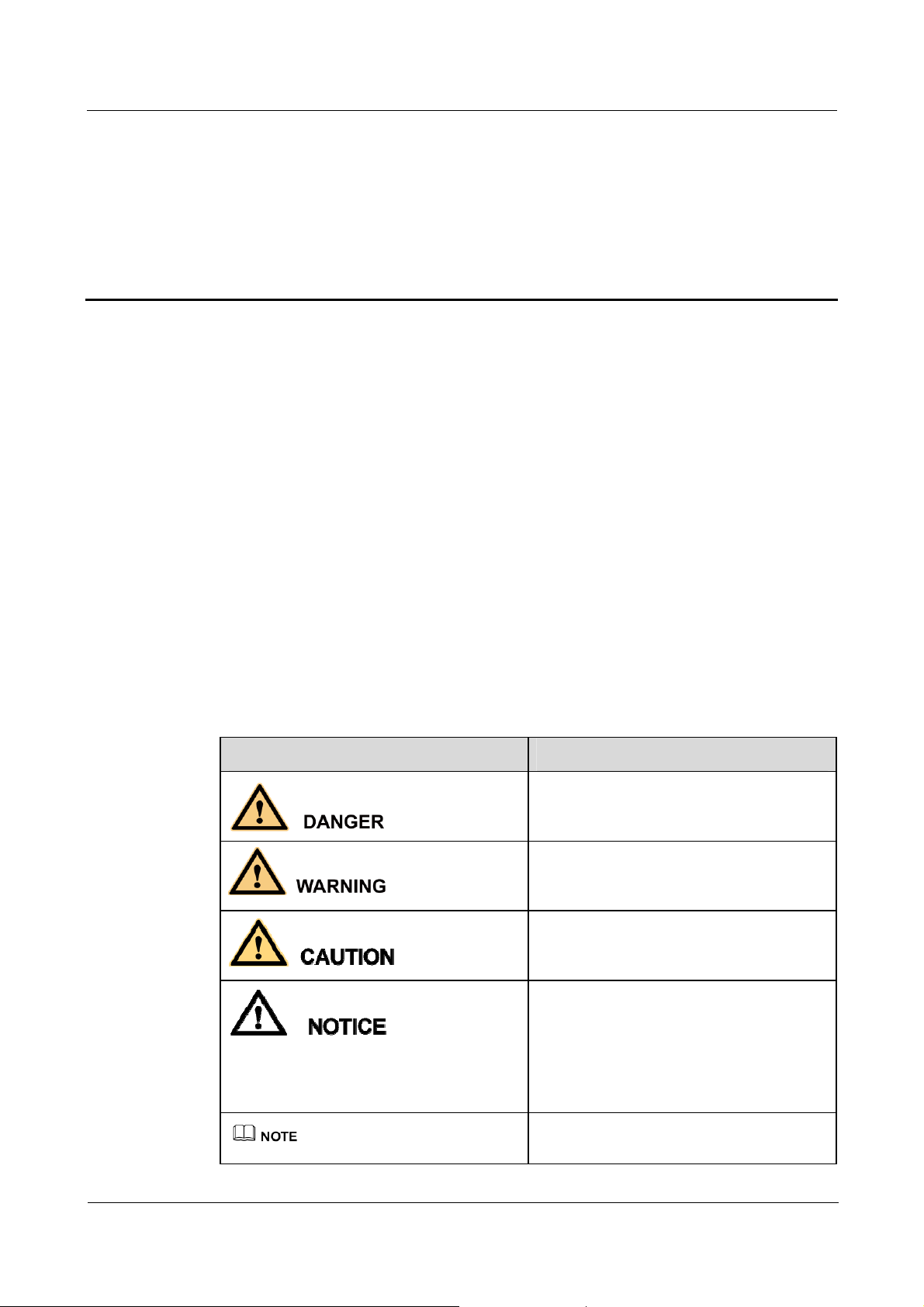
Symbol Conventions
The symbols that may be found in this docume nt are defined as follows.
Symbol Description
Indicates an imminently hazardous situation
which, if not avoided, will result in death or
serious injury.
Indicates a potentially hazardous situation
which, if not avoided, could result in death
or serious injury.
Indicates a potentially hazardous situation
which, if not avoided, may result in minor
or moderate injury.
Indicates a potentially hazardous situation
which, if not avoided, could result in
equipment damage, data loss, performance
deterioration, or unanticipated results.
NOTICE is used to address practices not
related to personal injury.
Calls attention to important information,
best practices and tips.
Issue 01 (2015-02-06)
华为专有和保密信息
版权所有 © 华为技术有限公司
iii
Page 4

AP4030DN Quick Start Guide About This Document
Symbol Description
NOTE is used to address information not
related to personal injury, equipment
damage, and environment deterioration.
Change History
Changes between document issues are cumulative. The latest document issue contains all
changes made in previous issues.
Issue 01 (2014-11-07)
Initial commercial release
Issue 01 (2015-02-06)
华为专有和保密信息
版权所有 © 华为技术有限公司
iv
Page 5

AP4030DN Quick Start Guide Contents
Contents
About This Document ................................................................................................................... iii
1 Indoor AP Overview ..................................................................................................................... 6
1.1 Device Structure .......................................................................................................... ................................................. 6
1.2 Indicator Description .................................................................................................................................................... 7
1.3 Basic Specifications ...................................................................................................................................................... 9
1.4 Global Environmental Compliance............................................................................................................................... 9
2 AP Installation ............................................................................................................................. 11
2.1 Preparing for Installation ............................................................................................................................................ 1 1
2.2 Unpacking the Equipment ................................................................................................... ....................................... 12
2.3 Determining the Installation Position ......................................................................................................................... 13
2.4 Installing the AP ......................................................................................................................................................... 14
2.4.1 W a ll Mounting ......................................................................................................................................................... 14
2.4.2 Ceiling Mounting ..................................................................................................................................................... 15
2.4.3 T-rail Mounting ........................................................................................................................................................ 16
2.5 Installing the Security Lock ........................................................................................................................................ 17
2.6 Connecting Cables ...................................................................................................................................................... 18
2.7 Powering on the AP .................................................................................................................................................... 19
3 Logging In to the AP ................................................................................................................... 20
3.1 Logging In to the AP Through the Console Port ......................................................................................................... 20
3.2 Logging In to the AP Using STelnet ........................................................................................................................... 21
3.3 Logging In to the AP Using a Web Client ................................................................................................................... 23
Issue 01 (2015-02-06)
华为专有和保密信息
版权所有 © 华为技术有限公司
v
Page 6

AP4030DN Quick Start Guide Contents
1 Indoor AP Overview
About This Chapter
The cost-effective AP4030DN supports 2 x 2 MIMO and provides comprehensive service
support capabilities. It is deployed indoors and features high reliability, high security, simple
network deployment, automatic AC discovery and configuration, and real-time management
and maintenance. Huawei AP4030DN complies with IEEE 802.11ac and can provide gigabit
access for wireless users. This high capacity greatly improves user experience on wir eless
networks.
Huawei indoor APs are especially applicable to places with simple building structure, small
size, dense users, and high capacity demands, such as small-size conference rooms, bars, and
leisure centers. They can be flexibly deployed according to surrounding environment.
1.1 Device Structure
1.2 Indicator Description
1.3 Basic Specifications
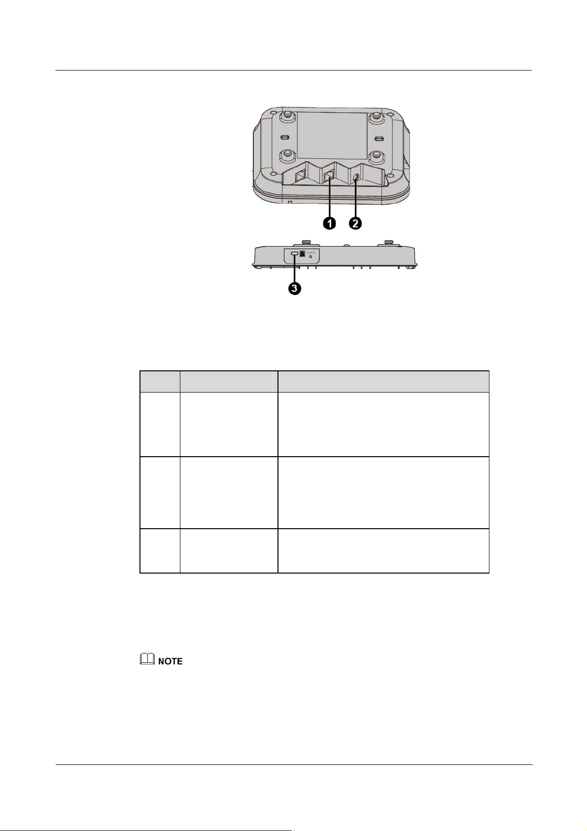
1.1 Device Structure
Figure in Figure 1-1 shows the appearance of AP4030DN.
Figure 1-1 Appearance of AP4030DN.
Issue 01 (2015-02-06)
华为专有和保密信息
版权所有 © 华为技术有限公司
6
Page 7
AP4030DN Quick Start Guide Contents
Table in Table 1-1 shows the interface of AP4030DN.
Table 1-1 Interfaces on AP4030DN
No. Name Description
1 GE/PoE 10/100/1000M bit/s interface: connects to the
2 DC power adapter The AP supports the PoE power supply and DC
3 Security slot Fasten the cable of the security lock to an
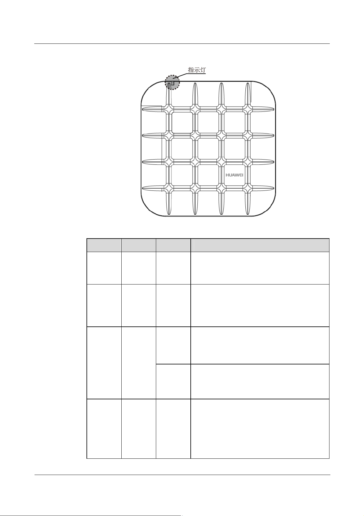
1.2 Indicator Description
The following information describes indicators on the AP4030DN.
wired Ethernet. The interface can connect to
a PoE power supply to provide power for the
AP.
power supply.
To connect the AP to a DC power source, use
the power adapter delivered with the AP;
otherwise, the AP maybe damaged.
immovable object around, and insert the
security lock into the security slot and lock it.
Issue 01 (2015-02-06)
The actual indicator color may vary according to temperature.
After an AP is powered on, you can run the led off command on the AC to turn off all AP indicators.
To restore the indicators to normal working status, run the led on command.
The AP4030DN has indicators located inside the panel. The indicators turn on after the AP is
powered on.
华为专有和保密信息
版权所有 © 华为技术有限公司
7
Page 8
AP4030DN Quick Start Guide Contents
Figure 1-2 Indicator on the AP4030DN
Table 1-2 Description of the indicator on the AP4030DN
Type Color Status Description
Default
status after
Green Steady on The AP is just powered on and the software is not
started yet.
power-on
Software
startup
status
Green Steady on
after
blinking
After the system is reset and starts uploading the
software, the indicator blinks green once. Until the
software is uploaded and started, the indicator
remains steady green.
once
Running
status
Green Blinking
once every
2s (0.5
Hz)
Blinking
once every
5s (0.2
Hz)
The system is running properly, the Ethernet
connection is normal, and STAs are associated
with the AP.
The system enters the Uboot CLI.
The system is running properly, the Ethernet
connection is normal, and no STA is associated
with the AP. The system is in low power
consumption state.
Issue 01 (2015-02-06)
Alarm Green Blinking
once every
0.25s (4
Hz)
华为专有和保密信息
版权所有 © 华为技术有限公司
The software is being upgraded.
After the software is uploaded and started, the
AP requests to go online on the AC and
maintains this state until it goes online
successfully on the AC (before the CAPWAP
link is established).
The AP fails to go online on the AC (the
8
Page 9

AP4030DN Quick Start Guide Contents
Type Color Status Description
CAPWAP link disconnects).
Fault Red Steady on A fault that affects services has occurred, such as a
DRAM detection failure or system software
loading failure. The fault cannot be automatically
rectified and must be rectified manually.
1.3 Basic Specifications
Table in Table 1-3 shows the specifications of AP4030DN.
Table 1-3 Basic specifica tions of th e AP4030DN
Item Description
Technical
specifications
Power specifications Power input
PoE -48V DC,0.35A
Environment
specifications
Dimensions (H x W
x D)
Weight 0.4kg (not include mounting bracket)
System memory
Maximum power
consumption
Operating
temperature
Storage temperature
Operating humidity
Ingress Protection
Rating
180mm×180mm×54.5mm (not include
mounting bracket)
256MB DDR2
32 MB Flash
12V±10%, 2A
10.2W
0℃~+45℃
-40℃~+70℃
5%~95%((non-condensing)
IP41
Atmospheric
pressure
53kPa~106kPa
1.4 Global Environmental Compliance
This product has been tested and complies with the following certification:
European Union RoHS: 2002/95/EC 2011/65/EU EN50581:2012
REACH: 1907/2006
Issue 01 (2015-02-06)
华为专有和保密信息
版权所有 © 华为技术有限公司
9
Page 10

AP4030DN Quick Start Guide Contents
WEEE: 2002/96/EC 2012/19/EU
China RoHs: SJ/T 11363-2006
本信息适用于华为在中华人民共和国销售的电子信息产品
This information applies only to Huawei Electronic Information Products sold in the People’s Republic of
China.
部件名称
(Parts)
电路模块
铅
(Pb) 汞 (Hg) 镉 (Cd)
×
有毒有害物质或元素(Hazardous Substance)
六价铬
(Cr6+)
多溴联苯
(PBB)
多溴二苯醚
(PBDE)
O O O O O
(circuit modules)
电缆及电缆组件
O O O O O O
(Cables &
Cable assemblies)
金属部件
O O O O O O
(Metal Parts)
塑料和聚合物部件
O O O O O O
(Plastic and Polymeric Parts)
O:
表示该有毒有害物质在该部件所有均质材料中的含量在 SJ/T11363 - 2006 标准规定的限量要求下。
Indicates that the concentration of the hazardous substance in all homogeneous materials in the parts is below the
relevant threshold of the SJ/T11363-2006 standard.
X:
表示该有毒有害物质至少在该部件的某一均质材料中的含量超出 SJ/T11363-2006 标准规定的限量要求。
Indicates that the concentration of the hazardous substance of at least one of all homogeneous materials in the
parts is above the relevant threshold of the SJ/T11363-2006 standard.
对销售之日的所售产品,本表显示华为公司供应链的电子信息产品可能包含这些物质。注意:在所售产
品中可能会也可能不会含有所有所列的部件。
This table shows where these substances may be found in the supply chain of Huawei products, as of the date of
sale of the enclosed product. Note that some of the component types listed above may or may not be a part of the
enclosed product.
Issue 01 (2015-02-06)
华为专有和保密信息
版权所有 © 华为技术有限公司
10
Page 11

AP4030DN Quick Start Guide Contents
2 AP Installation
About This Chapter
2.1 Preparing for Installation
2.2 Unpacking the Equipment
2.3 Determining the Installation Position
2.4 Installing the AP
2.1 Preparing for Installation
This section describes safety precautions and tool preparations for AP installation.
Safety Precautions
Take proper measures to prevent injuries and device damage.
Place the device in a dry and flat position away from any liquid and prevent the device
from slipping.
Keep the device clean.
Do not put the device and tools in the aisles.
This device uses non-harmonized frequency and is intended for use in all European
countries.
The WLAN can be operated in the EU without restriction indoors, but cannot be
operated outdoors.
A 20cm separation distance needs to be maintained to ensure compliance with the
European RF Exposure limits set by ICNIRP
Only the qualified personnel are permitted to install and remove the device and its accessories.
Before installation and operation, read the safety precautions carefully.
Tool Preparation
To install APs, prepare tools listed in Table 2-1。
Issue 01 (2015-02-06)
华为专有和保密信息
版权所有 © 华为技术有限公司
11
Page 12

AP4030DN Quick Start Guide Contents
Table 2-1 Tools
Phillips screwdriver
(M4)
ESD gloves
Diagonal pliers
Network cable tester
Torque screwdriver
3mm/5mm
(M3-M6)
Utility knife
RJ45 crimping tool
Multimeter
Marker
Cable cutter
Wire stripper
Level
2.2 Unpacking the Equipment
Before unpacking the carton, ensure that the packing carton is intact and not damaged or
soaked. Stop unpacking if the equipment is rusted or soggy. Then, investigate causes and
contact the supplier.
Usually, the packing list contains the following items.
AP
Mounting Bracket
Power adapter (optional)
Quick Start Guide
Wa rranty card
Issue 01 (2015-02-06)
华为专有和保密信息
版权所有 © 华为技术有限公司
12
Page 13

AP4030DN Quick Start Guide Contents
2.3 Determining the Installation Position
When determining the AP installation position, comply with the following rules:
Try to reduce the number of obstacles, such as walls, between the AP and user terminals.
Install the AP away from electronic devices that can cause radio interference, such as the
microwave oven.
Install the AP in a hidden position that does not affect daily lives and work of residents.
Install the AP in a site that is free from leaking or dripping water, heavy dew, and
humidity, and take protective measures to prevent water from flowing into the equipment
along the cable.
Indoor APs are usually mounted on a wall or ceiling using sheet metal mounting brackets. The
installation position is determined by the site survey. There must be at least 200 mm clearance
between the cabling end of the AP and the wall. Figure 2-1 shows dimension and Figure 2-2
shows space requirements.
Figure 2-1 Dimension of AP4030DN(Unit: mm)
Issue 01 (2015-02-06)
华为专有和保密信息
版权所有 © 华为技术有限公司
13
Page 14

AP4030DN Quick Start Guide Contents
Figure 2-2 Mounting an AP(Unit: mm)
2.4 Installing the AP
2.4.1 Wall Mounting
1. Fix the mounting bracket to the wall, adjust the installation position, and use the marker
to mark the drilling positions where expansion screws are installed.
2. Use a 6 mm drill bit to drill 25 mm to 30 mm deep holes in the drilling positions.
Hammer the expansion tubes into the holes until the expansion tubes are completely
embedded into the wall.
Issue 01 (2015-02-06)
华为专有和保密信息
版权所有 © 华为技术有限公司
14
Page 15

AP4030DN Quick Start Guide Contents
Fix the mounting bracket to the wall and use the Phillips screwdriver to fasten three expansion
screws into the expansion.
3. Align the mounting screws at the rear of the AP with the mounting holes on the
mounting bracket and hang the AP on the bracket. Press the AP downwards to secure the
AP on the wall.
2.4.2 Ceiling Mounting
Issue 01 (2015-02-06)
华为专有和保密信息
版权所有 © 华为技术有限公司
15
Page 16

AP4030DN Quick Start Guide Contents
1. Remove a ceiling tile, determine locations of mounting holes based on the distance
between two installation holes on the mounting bracket, use a hammer drill to drill
hole on the ceiling tile, and fix the mounting bracket to the ceiling tile.
2. Hang the AP on the mounting holes by aligning the mounting screws at the rear of
the AP with the mounting screws on the bracket and push the AP horizontally to
secure the AP.
The screws provided for ceiling-mounting of APs are 30 mm long and can be used to fix an
AP on a ceiling not thicker than 15 mm. To install APs on thicker ceilings, you need to
purchase longer screws.
Ensure that the AP is correctly installed on the mounting bracket and there must be 200 mm
space above and around the AP for maintenance.
2.4.3 T-rail Mounting
1. Remove two ceiling tiles around the T-rail (1), use screws (2) to fix the adjustable buckle
(3) to the mounting bracket (4), hook the adjustable buckle to the T-rail, and secure the
screw on the adjustable buckle to fasten the mounting bracket and T-rail. Remove two
ceiling tiles around the T-rail, use screws to fix the adjustable buckle to the mounting
Issue 01 (2015-02-06)
华为专有和保密信息
版权所有 © 华为技术有限公司
16
Page 17

AP4030DN Quick Start Guide Contents
bracket, hook the adjustable buckle to the T-rail, and secure the screw on the adjustable
buckle to fasten the mounting bracket and T-rail.
2. Hang the AP on the mounting holes by aligning the mounting screws at the rear of the AP
with the mounting screws on the bracket and push the AP horizontally to secure the AP.
1. Before fixing the adjustable buckle with a screw, you need to adjust the buckle to a
proper position based on the T-rail width.
2. Ensure that the AP is correctly installed on the mounting bracket and there must be 200
mm space above and around the AP for maintenance.
2.5 Installing the Security Lock
There is a security slot on the AP. You can lock the AP to an immovable object to prevent the
AP against theft. The detailed procedures are as follows:
1. Fasten the cable of the security lock to an immovable object around.
2. Insert the security lock into the security slot and lock it.
Issue 01 (2015-02-06)
华为专有和保密信息
版权所有 © 华为技术有限公司
17
Page 18

AP4030DN Quick Start Guide Contents
You need to purchase the security lock separately.
2.6 Connecting Cables
Figure 2-3 and Table 2-2 shows interface and cable connection of AP4030DN。
Figure 2-3 Interfaces of the AP4030DN
Table 2-2 Cable Connection
No. Cable Description
1 Ethernet cable The network cables used are category-5 enhanced or higher
twisted pairs.
Ensure that the AP is connected to the Ethernet using the
Ethernet cable that works properly. If the Ethernet cable is
not working properly, for example, RJ45 connectors are
short- circuited, the AP may fail to be powered on or fail to
work. Before connecting an Ethernet cable to the AP, use
the cable test tool to check whether the cable is qualified. If
the cable is unqualified, replace it.
2 DC power adapter The AP supports the PoE power supply and DC power
supply.
To connect the AP to a DC power source, use the power
adapter delivered with the AP; otherwise, the AP maybe
damaged.
Issue 01 (2015-02-06)
华为专有和保密信息
版权所有 © 华为技术有限公司
18
Page 19

AP4030DN Quick Start Guide Contents
Pay attention to the following points when installing network cables
Before connecting an Ethernet cable to the AP, use the cable test tool to check whether
the cable is qualified. If the cable is unqualified, replace it.
Do not connect the service network cable to the console port. Otherwise, the AP may be
damaged when the PoE power supply is used.
Before removing network cables or power cables, remove the AP from the mounting
bracket first to prevent damage to the network cables or power cables.
The cable cannot exceed 100 meters.
2.7 Powering on the AP
You can check the power-on status by observing indicators on the AP. For details, see 1.2
Indicator Description
Do not frequently power on and off an AP.
Issue 01 (2015-02-06)
华为专有和保密信息
版权所有 © 华为技术有限公司
19
Page 20

AP4030DN Quick Start Guide 3 Logging In to the AP
3 Logging In to the AP
About This Chapter
3.1 Logging In to the AP Through the Console Port
3.2 Logging In to the AP Using STelnet
3.3 Logging In to the AP Using a Web Client
3.1 Logging In to the AP Through the Console Port
This section describes how to log in to the AP through the console port. After logging in to the
AP, you can configure the AP using commands.
Step 1 Connect a PC to the AP using a console cable. Connect the RJ45 connector to the console port
of the AP and the DB9 connector to the serial port of a PC.
Step 2 Run the terminal emulation program on the PC. For example, to open the HyperTerminal of
Windows XP on the PC, choose Start > Programs > Accessories >Communications >
HyperTerminal. Enter a connection name and click OK.
Step 3 Select the serial port used on the PC and click OK.
Step 4 Set communication parameters, click Restore Defaults, and then click OK.
Step 5 Press Enter until the command line prompt of the user view, such as <Enterprise AP>, is
displayed. Then, you enter the user configuration interface. (The following information is
only for reference.)
Issue 01 (2015-02-06)
The default user name and password are respectively admin and admin@hua wei.com.
The password entered in interactive mode is not displayed on the screen.
华为专有和保密信息
版权所有 © 华为技术有限公司
20
Page 21

AP4030DN Quick Start Guide 3 Logging In to the AP
You can run commands to configure the AP. Enter a question mark (?) whenever you need
help.
3.2 Logging In to the AP Using STelnet
This section describes how to log in to the AP using STelnet. After logging in to the AP, you
can configure the A P using commands.
Before logging in to the device through STelnet, complete the following tasks:
Starting the device properly
Preparing network cables used to connect device interfaces.
Ensuring that the IP address 169.254.1.1 and subnet mask 255.255.0.0 have been configured on
VLANIF 1 of the device before the delivery and GE0/0/0 has been added to VLAN 1 by default.
Configuring the PC's IP address and subnet mask. The IP address must be on the network
segment 169.254.0.0/16 but cannot be 169.254.1.1. 169.254.1.100 is recommended. The
subnet mask is 255.255.0.0.
Before the device is delivered, the STelnet service has been configured on the device. The STelnet
interface number is 22, and the default user name and password are respectively admin and
admin@huawei.com.
Use the SSH client software to log in to the device through STelnet from a terminal. The
third-party software PuTTY is used as an example here.
Step 1 After the device is powered on, connect the PC's network interface to GE0/0/0 of the device
using network cables
Ping 169.254.1.1 from the PC to check whether the device can be pinged successfully. If the ping
operation fails, check whether the PC's IP address is correct or replace the network cable.
Step 2 Use the PuTTY software to log in to the device, enter the device IP address, and select the
SSH protocol type.
Issue 01 (2015-02-06)
华为专有和保密信息
版权所有 © 华为技术有限公司
21
Page 22

AP4030DN Quick Start Guide 3 Logging In to the AP
Figure 3-1 PuTTY Configuration page
Step 3 Click Open. Enter the user name and password at the prompt, and press Enter. You have
logged in to the device. (The following information is only for reference.)
login as: admin
Sent username "admin"
admin@169.254.1.1's password:
<Huawei>
It is recommended that you change the initial user name and password after login.
Issue 01 (2015-02-06)
华为专有和保密信息
版权所有 © 华为技术有限公司
22
Page 23

AP4030DN Quick Start Guide 3 Logging In to the AP
3.3 Logging In to the AP Using a Web Client
Pre-configuration Tasks
Before configuring users to log in to the AP using HTTP, complete the following task:
Configure reachable routes between the terminal and the AP.
The web management system is enabled on the AP before delivery. The default IP address of the web
management system is 169.254.1.1 and the mask is 255.255.0.0. The web management system
provides a default user account, with the user name admin and password admin@huawei.com. You
are advised to change the user name and password on your first login. Assign your PC an IP address
on the same network segment as the default IP address of the web management system, and connect
the PC to the GE interface. Start the web browser on the PC and visit http://169.254.1.1 to log in to
the web management system.
You can only log in to the FAT AP using the web platform.
Procedure
Step 1 Open a web browser on a PC, and enter the management address in the format of
Step 2 Click Login or press Enter. The web system home page is displayed. You can manage and
http://169.254.1.1 in the address bar. Ensure that the PC and AC can communicate with each
other. Then press Enter. Set the language, user name, and password. The HTTPS login
URL is displayed in the address box indicating that the system has gone to the HTTPS login
page.
You can also enter https://IP address in the address box to log in to the AP using HTTPS. HTTPS
ensures security of login information during login and security of data exchanged during subsequent
operations.
maintain the equipment. For details, see the Huawei Wireless Access Points Web-based
Configuration.
Issue 01 (2015-02-06)
华为专有和保密信息
版权所有 © 华为技术有限公司
23
Page 24

AP4030DN Quick Start Guide 4 Caution
4 Caution
4.1 Caution
Issue 01 (2015-02-06)
华为专有和保密信息
版权所有 © 华为技术有限公司
24
 Loading...