

Page 1

user's guide
version 3.0
web tools
www.hp.com
Page 2

Notice
© Hewlett-Packa rd C om pa n y, 2001. All rights reser v ed .
Edition: E1201
Hewlett-Packard Company makes no warranty of any kind with
regard to this material, including, but not limited to, the implied
warranties of merchantability and fitness for a particular purpose.
Hewlett-Packard shall not be liable for errors contained herein or for
incidental or consequential damages in connection with the
furnishing, performance, or use of this material.
This document co nta in s proprietary information, whic h is p rote c te d
by copyright. No part of this document may be photocopied,
reproduced, or translated into another language without the prior
written consent of Hewlett-Packard. The information contained in
this document is subject to change without notice.
Use, duplication, or disclosure by government is subject to
restrictions as set forth in subdivision (c) (1) (ii) of the Rights in
Technical Data and Computer Software Clause at DFARS
252.227.7013.
Warranty
If you have any questions about the warranty for this produc t,
contact your dealer or local Hewlett-Packard sales representative.
Trademarks
BROCADE, the Brocade B weave logo, Brocade: the Intelligent
Platform for Networking Storage, SilkWorm, and SilkWorm
Express, are trademarks or registered trademarks of Brocade
Communications Systems, Inc. or its subsidiaries in the United
States and/or in other countries.
All other bran ds, pro duct or serv ice na mes are or may b e trade marks
or service marks of, and ar e used to identify pr oducts of services of
their respective owners.
Safety notic es
Any servicing, adjustment, maintenance, or repair must be
performed only by authorized service-trained personnel.
Page 3

Web Tools User’s Guide i
Contents
Preface
About This Guide . . . . . . . . . . . . . . . . . . . . . . . . . . . . . . . . . . . . . . . . . . v
Related Publications . . . . . . . . . . . . . . . . . . . . . . . . . . . . . . . . . . . . . . . . v
System Requirements and Compatibility . . . . . . . . . . . . . . . . . . . . . . . . vii
Getting Help . . . . . . . . . . . . . . . . . . . . . . . . . . . . . . . . . . . . . . . . . . . . . . vii
Getting Software Updates. . . . . . . . . . . . . . . . . . . . . . . . . . . . . . . . . . . . vii
Chapter 1 Introducing Web Tools
Overview. . . . . . . . . . . . . . . . . . . . . . . . . . . . . . . . . . . . . . . . . . . . . . . . . 1-1
Advantages of Web Tools. . . . . . . . . . . . . . . . . . . . . . . . . . . . . . 1-1
Capabilities of Web Tools. . . . . . . . . . . . . . . . . . . . . . . . . . . . . . 1-2
Web Tools Main Views. . . . . . . . . . . . . . . . . . . . . . . . . . . . . . . . 1-3
Chapter 2 Installing Web Tools
Requirements . . . . . . . . . . . . . . . . . . . . . . . . . . . . . . . . . . . . . . . . . . . . . 2-1
Switch Requirements and Compatibility . . . . . . . . . . . . . . . . . . 2-1
Workstation Requirements . . . . . . . . . . . . . . . . . . . . . . . . . . . . . 2-1
Installation . . . . . . . . . . . . . . . . . . . . . . . . . . . . . . . . . . . . . . . . . . . . . . . 2-2
Installing a Web Browser . . . . . . . . . . . . . . . . . . . . . . . . . . . . . . 2-2
Configuring the Web Browser . . . . . . . . . . . . . . . . . . . . . . . . . . 2-2
Installing the Java Plug-in on the Workstation . . . . . . . . . . . . . . 2-3
Launching Web Tools. . . . . . . . . . . . . . . . . . . . . . . . . . . . . . . . . . . . . . . 2-4
Chapter 3 Fabric View
Fabric View. . . . . . . . . . . . . . . . . . . . . . . . . . . . . . . . . . . . . . . . . . . . . . . 3-1
Fabric Events View. . . . . . . . . . . . . . . . . . . . . . . . . . . . . . . . . . . . . . . . . 3-5
Page 4

ii Fabric Manager User’s Guide
Fabric Topology View. . . . . . . . . . . . . . . . . . . . . . . . . . . . . . . . . . . . . . . 3-7
Name Server Table View . . . . . . . . . . . . . . . . . . . . . . . . . . . . . . . . . . . . 3-8
The Name Server Table also includes the following columns: . . . . . . . 3-10
Zone Administration View . . . . . . . . . . . . . . . . . . . . . . . . . . . . . . . . . . . 3-10
Switch/Port Level Zoning. . . . . . . . . . . . . . . . . . . . . . . . . . . . . . 3-12
WWN Level Zoning . . . . . . . . . . . . . . . . . . . . . . . . . . . . . . . . . . 3-23
AL_PA Level Zoning . . . . . . . . . . . . . . . . . . . . . . . . . . . . . . . . . 3-33
Mixed Level Zoning . . . . . . . . . . . . . . . . . . . . . . . . . . . . . . . . . . 3-40
Chapter 4 Switch View
Switch Events View . . . . . . . . . . . . . . . . . . . . . . . . . . . . . . . . . . . . . . . . 4-4
Fabric Watch View . . . . . . . . . . . . . . . . . . . . . . . . . . . . . . . . . . . . . . . . . 4-8
Alarm Notifications Tab . . . . . . . . . . . . . . . . . . . . . . . . . . . . . . . 4-8
Configure Thresholds . . . . . . . . . . . . . . . . . . . . . . . . . . . . . . . . . 4-10
Current Settings Tab . . . . . . . . . . . . . . . . . . . . . . . . . . . . . . . . . . 4-17
Performance Monitor . . . . . . . . . . . . . . . . . . . . . . . . . . . . . . . . . . . . . . . 4-17
Graph Types . . . . . . . . . . . . . . . . . . . . . . . . . . . . . . . . . . . . . . . . 4-19
Performance Monitor Menus . . . . . . . . . . . . . . . . . . . . . . . . . . . 4-20
Performance Graphs Menu. . . . . . . . . . . . . . . . . . . . . . . . . . . . . 4-27
Additional Options . . . . . . . . . . . . . . . . . . . . . . . . . . . . . . . . . . . 4-37
. . . . . . . . . . . . . . . . . . . . . . . . . . . . . . . . . . . . . . . . . . . . . . . . . . . . . . . . 4-38
Page 5

Web Tools User’s Guide iii
Administrative Interface . . . . . . . . . . . . . . . . . . . . . . . . . . . . . . . . . . . . . 4-38
Switch Settings Tab. . . . . . . . . . . . . . . . . . . . . . . . . . . . . . . . . . . 4-40
User Admin Tab . . . . . . . . . . . . . . . . . . . . . . . . . . . . . . . . . . . . . 4-42
Firmware/Configuration File Administration Tab . . . . . . . . . . . 4-43
SNMP Tab. . . . . . . . . . . . . . . . . . . . . . . . . . . . . . . . . . . . . . . . . . 4-45
License Administration Tab . . . . . . . . . . . . . . . . . . . . . . . . . . . . 4-47
Remote Switch Tab (Optional Software) . . . . . . . . . . . . . . . . . . 4-49
QuickLoop Tab . . . . . . . . . . . . . . . . . . . . . . . . . . . . . . . . . . . . . . 4-50
Configure Tab . . . . . . . . . . . . . . . . . . . . . . . . . . . . . . . . . . . . . . . 4-53
Extended Fabric Tab (Optional Software) . . . . . . . . . . . . . . . . . 4-55
Network Configuration Tab . . . . . . . . . . . . . . . . . . . . . . . . . . . . 4-57
Port Settings Tab. . . . . . . . . . . . . . . . . . . . . . . . . . . . . . . . . . . . . 4-58
Routing Tab. . . . . . . . . . . . . . . . . . . . . . . . . . . . . . . . . . . . . . . . . 4-60
Trunk Information Tab . . . . . . . . . . . . . . . . . . . . . . . . . . . . . . . . 4-62
Report Tab. . . . . . . . . . . . . . . . . . . . . . . . . . . . . . . . . . . . . . . . . . 4-63
Telnet Interface . . . . . . . . . . . . . . . . . . . . . . . . . . . . . . . . . . . . . . . . . . . . 4-64
Chapter 5 Port View
Port Information View . . . . . . . . . . . . . . . . . . . . . . . . . . . . . . . . . . . . . . 5-1
PortStats Tab. . . . . . . . . . . . . . . . . . . . . . . . . . . . . . . . . . . . . . . . 5-3
GBIC Tab . . . . . . . . . . . . . . . . . . . . . . . . . . . . . . . . . . . . . . . . . . 5-5
Loop Tab. . . . . . . . . . . . . . . . . . . . . . . . . . . . . . . . . . . . . . . . . . . 5-8
Glossary
Index
Page 6

iv Fabric Manager User’s Guide
Page 7

Web Tools User’s Guide v
Preface
Web Tools v3.0 is a standard feature on the HP Surestore FC 1Gb/2Gb Entry Switch 8B, FC
1Gb/2Gb Switch 8B, and FC 1Gb/2Gb Switch 16B products. It is supported on the HP Brocade
2400/2800 switches and the HP Surestore FC Switch 6164 running Fabric OS version a2.4.1 or
later, and on the FC Entry S witch 8B, FC Swit ch 8B, and FC 16B prod ucts using Fabr ic OS ve rsion
3.0.1b or later.
About This Guide
This guide provides the following information about Web Tools:
Related Publications
Related product information can be found in the following publications.
Provided with the FC Entry Switch 8B and FC Switch 8B:
• HP Surestore FC 1Gb/2Gb Entry Switch 8B and FC 1Gb/2Gb Switch 8B Getting Started
Guide (A7346-90902)
• HP Surestore FC 1Gb/2Gb Entry Switch 8B and FC 1Gb/2Gb Switch 8B Documentation
CD (A7346-11001)
Chapter 1
Introducing Web Tools
Provides an overview of Web Tools.
Chapter 2
Installing Web Tools
Provides instructions for installing Web Tools.
Chapter 3
The Fabric View
Provides information about configuring and using Web Tools
Fabric View.
Chapter 4
The Switch View
Provides information about configuring and using Web Tools
Switch View.
Chapter 5
The Port View
Provides information about configuring and using Web Tools
Port View.
Page 8

vi Web Tools User’s Guide
Provided on the FC Entry Switch 8B and FC Switch 8B Documentation CD, and at the HP Web site
at
http://www.hp.com/support/fc8B:
• HP Surestore FC 1Gb/2Gb Entry Switch 8B and FC 1Gb/2Gb Switch 8B Getting Started
Guide (A7346-90902)
• HP Sur est o re FC 1Gb/2Gb Ent r y Swit c h 8B and FC 1Gb/2 Gb Swi tc h 8B Ins tal lat i on and
Reference Guide
• Fabric OS Reference Manual, version 3. 0
• Fabric OS Procedures Guide, version 3.0
• Fabric OS Version 3.0.1b Release Notes
• Fabric Watch User’s Guide, version 3.0
• QuickLoop User’s Guide, version 3.0
• Web Tools User’s Guide, version 3.0
• Distributed Fabrics User’s Guide, version 3.0
• Zoning User’s Guide, version 3.0
• MIB Reference Manual, version 3.0
• IS L Tr un ki ng User ’s Gu ide , version 3.0
• Advanced Performance Monitoring User’s Guide, version 3.0
• Me rg i ng Hete r og e neou s F abr ic s Ins t ru ctions
Provided with the FC 16B:
• HP Surestore FC 1Gb/2Gb Switch 16B Quick Start Guide (A7340-96002)
• HP Surestore FC 1Gb/2Gb Switch 16B Documentation CD (A7340-11001)
Provided on the FC 1Gb/2Gb Switch 16B Documentation CD and at the HP Web site at
http://www.hp.com/support/fc16B:
• HP Surestore FC 1Gb/2Gb Switch 16B Quick Start Guide (A7340-96002)
• HP Surestore FC 1Gb/2Gb Switch 16 B Installation and Reference Guide
• Fabric OS Reference Manual, version 3. 0
• Fabric OS Procedures Guide, version 3.0
• Fabric OS Version 3.0.1 Release Notes
• Fabric Watch User’s Guide, version 3.0
• QuickLoop User’s Guide, version 3.0
• Web Tools User’s Guide, version 3.0
• Distributed Fabrics User’s Guide, version 3.0
• Zoning User’s Guide, version 3.0
• MIB Reference Manual, version 3.0
• IS L Tr un ki ng User ’s Gu ide , version 3.0
• Advanced Performance Monitoring User’s Guide, version 3.0
• Me rg i ng Hete r og e neou s F abr ic s Ins t ru ctions
Information about Fi b re C hann e l st an dards and Fibre Channel in general can be f oun d o n t he Fi b re
Channel Industry Association Web site, located at
http://www.fibrechannel.com.
Page 9

Web Tools User’s Guide vii
System Requirements and Compatibility
Compatibility with other Products
Fabric OS version 3.0.1b or later can be installed and run on the FC Entry Switch 8B, FC Switch
8B, and FC 16B products.
The FC Entry Switch 8B, FC Switch 8B, and FC 16B switch running Fabric OS version 3.0.1b or
later can operate in the same fabric with the HP B rocad e 2 400 /2 800 an d F C 616 4 s wi t ches run ni ng
the a2.4.1 or later versions of Fabric OS.
For more informatio n ab out configuring FC Entry Switch 8B, F C Sw it ch 8 B, F C 1 6B , HP B rocad e
2400/2800, and FC 6164 products to operate in the same fabric, contact your switch supplier.
Getting Help
For information for the FC Entry Switch 8B and FC Switch 8B, visit the HP Web site at
http://www.hp.com/support/fc8B. For the most current technical support information for the FC
16B, visit the HP Web site at
http://www.hp.com/support/fc16B. This includes hardware and
software support, all repairs, and spare components.
Be prepared to provide the following information to the support personnel:
• Switch serial number
• Switch world wide name
• Output from the supportShow telnet command
• Detailed description of the problem
• Topology configuration
• Troubleshooting steps already performed
Getting Software Updates
For information on obtaining sof tware up dates co n tact you r HP acco unt r e pres entative or technical
support.
Page 10

viii Web Tools User’s Guide
Page 11

Web Tools User’s Guide 1-1
Chapter
1
Introducing Web Tools
This chapter provides the following information:
• Overview on page 1-1
• Advantages of Web Tools on page 1-1
• Capabilities of Web Tools on page 1-2
• Web Tools Main Views on page 1-3
Overview
Web Tools runs on Fabric OS version 3.0.1b or later and provides a graphical interface that allows
the administrator to monitor and manage entire fabrics and individual switches and ports from a
standard workstation.
Note: In this Guide references to GBIC in the text and on the product screens represent Small
Form Factor Pluggable units (SFPs).
Advantages of Web Tools
Web Tools is an excellent partner to the traditional Telnet commands, and in many ways can
provide faster and more effective results than can be achieved strictly through a Command Line
Interface.
Following are some of the features that make Web Tools an important part of the switch
management and administration process:
• Web Tools can be used simultaneously with Telnet commands. Simply open a second window
and you can take advantage of the benefits of both interfaces at the same time.
• Web Tools can help you find the appropriate Telnet command to perform a desired function.
For instance, you can perform a function using Web Tools, and watch in a second window as
the Telnet commands are displayed.
• Web Tools can be used from a standard workstation and provides the user the advantage of
being “virtually” in front of any fabric, switch, or port.
• Web Tools makes zoning a simple “click and drag” process, rather than having to tediously
type out IP addresses and port numbers to put in a configuration.
• Web Tools provides the “Performance Monitor” feature. This feature allows you to view the
status and traffic of a switch or port in seconds by easily creating a variety of ef fective gr aphs .
• Web Tools is easy and intuitive to use.
Page 12
1-2 Web Tools User’s Guide
Introducing Web Tools
1
Capabilities of Web Tools
Web Tools provides the following information and capabilities:
• Monitoring and managing the entire fabric.
• Monitoring and managing individual switches.
• Monitoring and managing individual ports.
When monitoring and managing the entire fabric, Web Tools allows you to perform the following
functions:
When monitoring and managing individual switches, Web Tools allows you to perform the
following functions:
View the status of all the switches in the fabric. See Fabric View on page 3-1.
Access event logs for entire fabric. See Fabric Events View on page 3-5
Set-up and manage Zoning functions. See The Name Server Table also includes
the following columns: on page 3-10.
Access to the Name Server Table. See Name Server Table View on page 3-8.
Access Telnet functions. See Telnet Interface on page 4-64.
Use switch beaconing for rapid identification in
large fabric environments.
See Beacon on page 4-4.
Name and zone QuickLoops. See Loop Tab on page 5-8 or the
QuickLoop Tab on page 4-50.
View summary information about each switch. See Config on page 3-48.
View event logs for individual switches. See Switch Events View on page 4-4.
Perform switch configuration and
administration.
See Administrative Interface on page 4-38,
the Switch Settings Tab on page 4-40, and
the Current Settings tab in the Fabric
Watch View on page 4-17.
Use the ability to upgrade Fabric OS and
license key administration.
See Firmware/Configuration File
Administration Tab on page 4-43.
Use report capability for switch configuration
information.
See Report Tab on page 4-63.
Page 13
Web Tools User’s Guide 1-3
Introducing Web Tools
1
When monitoring and managing individual ports, Web Tools allows you to perform the following
functions:
Web Tools Main Views
Web Tools provides access to and information about the fabric through a number of separate
windows, called “vie ws”, mak i ng i t possible to manage and monitor sev eral as pects o f the fabric at
the same time.
The main views available through Web Tools are:
1. Fabric View
2. Switch View
3. Port Information View
View the port status. See PortStats Tab on page 5-3.
View information about GBIC (Gigabit
Interface Converter) Serial IDs.
See GBIC Tab on page 5-5.
Vi ew and manage loop informati on. See Loop Tab on page 5-8, Q uickLoop Tab
on page 4-50, or The Name Server Table
also includes the following columns: on
page 3-10.
Vi ew port performance, including frame coun ts
(frames in, frames out) and error counts.
See Current Settings tab in the Fabric
Watch View on page 4-17.
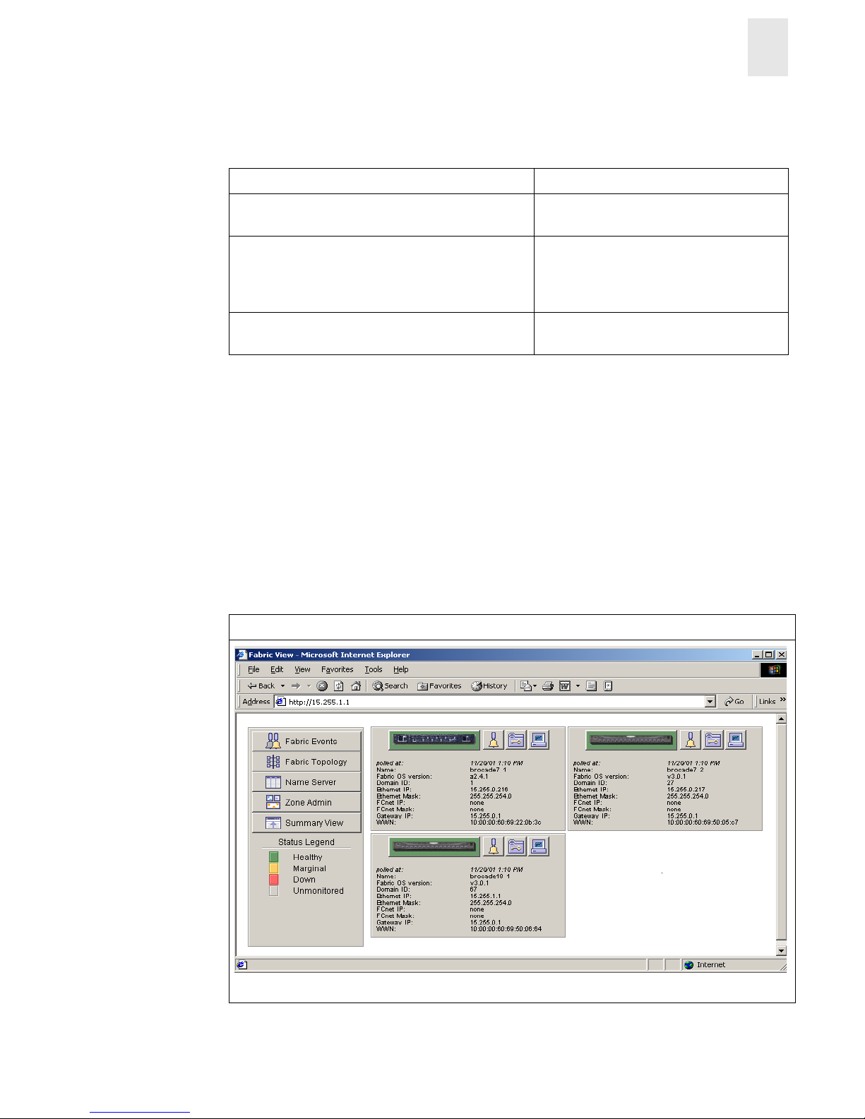
Initial Display Upon Launching Web Tools: Fabric View
Figure 1-1 Fabric View
Page 14

1-4 Web Tools User’s Guide
Introducing Web Tools
1
1. Fabric View Displays a control panel that provides access to fab ric-wide options, a panel
for each switch in the fabric, plus a legend that explains the meaning of the
background colors on the Switch icons. Each panel contains an icon that
represents the switch itself, in addition to icons for Switch Events and the
Administrative and Telnet interfaces. The background color of the switch
icon represents the status of that particular switch or Integrated Fabric (as
defined by the legend provided in the window).
Note: Switch status is calculated approximately once per second;
however the initial calculation does not occur until 30-60 seconds
after the switch is booted. It is calculated from the state of data
structures in the switch, and stored as the variable “switchStatus”.
Note: For all statuses that are based on erro rs per time interval, any errors
will cause the status to show faulty until the entire sample interval
has passed .
For information about the functions that are accessible through Fabric
View, see Fabric View on page 3-1.
Accessible from Fabric View: Switch View
Figure 1-2 Switch View
2. Switch View Displays informat ion abou t indi vidual switches, including a real-time view
of switch status. Accessed by selecting the Switch icon on a switch panel.
The Switch View is also the launch point for the Switch Events View,
T elnet Interface, Fabric W atch View, Administrative Interface, Perfo rmance
Vi ew, and Port Informati on View. It incl udes i cons that disp lay t he stat us of
the switch fans, temperature monitors, and beacon.
For information about the functions that are accessible through the Switch
View, see The items and information available in Switch View on page 4-2.
Page 15
Web Tools User’s Guide 1-5
Introducing Web Tools
1
Note: Each “main view” has several layers, or sub-views, that allow for more complex
functionality. For more information about what you can do with these views, see C hapter 3
Fabric View on page 3-1, Chapter 4 Telnet Interface on page 4-1, or Chapter 5 Port
Information View on page 5-1.
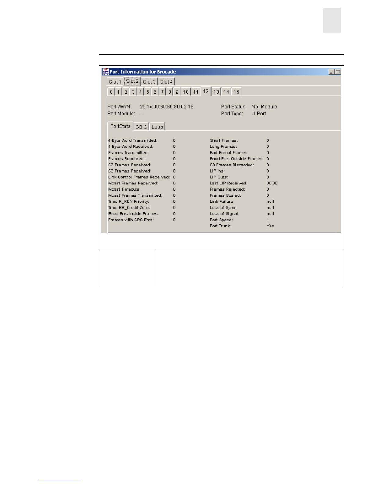
Accessible From Switch View: Port Information View
Figure 1-3 Port Information View
3. Port
Information
View
Displays statistics and status for the selected port, GBIC, or loop. Accessed
by selecting the icon for the relevant port in Switch View.
For information about the functions that are accessible through the Port
View, see Port Information View on page 5-1.
Page 16

1-6 Web Tools User’s Guide
Introducing Web Tools
1
Page 17

Web Tools User’s Guide 2-1
Chapter
2
Installing Web Tools
This chapter provides the following information:
• Requirements on page 2-1
• Installation on page 2-2
• Laun ching Web Tools on page 2-4
Requirements
The workstation and the switch must both meet specific requirements for the correct installation
and operation of Web Tools.
Switch Requirements and Compatibility
Compatibility with other HP Products
Fabric OS version 3.0.1b or later can be installed and run on FC Entry Switch 8B, FC Switch 8B,
and FC 16B.
Switches running Fabric OS version 3.0.1b or later can operate in the same fabric with HP Brocade
2400/2800 and HP Surestore FC Switch 6164 switches running a2.4.1 or later versions of Fabric
OS.
For more information about configuring HP Brocade 2400/2800, FC 6164, FC Entry Switch 8B,
FC Switch 8B, and FC 16B switches to operate in the same fabric, contact your switch su pplier.
Workstation Requirements
The following items are required for the correct installation and operation of Web Tools:
• One of the following operating systems:
• Solaris 2.61 or later
• Windows 98 or 2000
• Windows NT 4.0
• Adequate RAM (required for Windows operating systems only):
• 128 MB for fabric s of 21 switches or less
• 256 MB for fabrics containing more than 21 switches
Page 18

2-2 Web Tools User’s Guide
Installing Web Tools
2
• 5 MB of free disk space
• One of the following Web browsers:
• Netscape Communicator 4.6x or later.
• Internet Explorer 4.01 or later.
Note: The browser must be configured to work with Web T oo l s. F or in for mat ion about how
to do this, see Installi ng a Web Browser on page 2-2.
• The correct version of the Java plug-in for the operating system:
• Windows 98, NT, or 2000: Java plug-in up to the 1.2.2-008 version.
• Solaris: Java plug-in version 1.2.2-02 for Solaris, in cl udi ng the J a va p lug-i n patc h cr eat ed
by Sun for Solaris.
Installation
Preparing to use Web Tools to manage your fabric requires the following steps:
• Installation of one of the supported Web browsers on the workstation, if not already installed.
• Configuration of the Web browser for use with Web Tools.
• Installation of the required Java plug-in on the workstation, if not already installed.
Installing a Web Browser
If not already installed, install one of the following browsers:
• Netscape Communicator 4.6x or later (available at http://www.netscape.com).
• Internet Explorer 4.01 or later (available at http://www.microsoft.com).
Configuring the Web Browser
Specific browser settings are required for the correct operation of Web Tools with either Netscape
Communicator or Internet Explorer.
Configuring Netscape Communicator
The Web browser cache must be cleared after the installation of Fabric OS. Some browsers use
local cache copies of jar files and/or image files to improve performance (depending on th e options
selected in browser), which can cause incorrect display in Web Tools.
To remove cached files from Netscape Communicator:
1. Select Edit > Preferences.
2. Select Advanced in the left text box to expand it, then click Cache.
3. Select Clear Memory Cache on the Cache panel.
4. Select Clear Disk Cache.
5. Select OK.
Page 19

Web Tools User’s Guide 2-3
Installing Web Tools
2
6. Exit and relaunch the browser.
Configuring Internet Explorer
Correct operation of Web Tools with Internet Explorer requires clearing the browser cache after
installation, and specifying the appropriate settings for browser refresh frequency and process
model.
• The browser cache must be cleared after the installation of Fabric OS. The browser may use
local cache copies of jar files and/or image files to improve performance (depending on
options selected in browser), which can cause incorrect display.
To remove cached files from Internet Explorer:
1. Select Internet Options from the View menu if using Internet Explorer 4.x, or from the
Tools menu if using 5.x.
2. Select the General tab.
3. Click Delete Files... (under “Temporary Internet Files”).
4. Click OK, then exit and relaunch the browser.
• Browser pages must be refreshed at every visit to ensure the correct operation of the Switch
Admin feature.
To set the refresh frequency:
1. Select Internet Options from the View menu if using Internet Explorer 4.x, or from the
Tools menu if using 5.x.
2. Select the General tab and click Settings (under “Temporary Internet Files”).
3. Under “Check for newer versions of stored pages”, select “Every visit to the page”.
• The correct Browser Process Model must be selected.
T o select the Browser Process Model:
1. Select View > Internet Options if using Internet Explorer 4.x, or Tools > Internet
Options if using Internet Explorer 5.x.
2. Select the Advanced tab and click to expand the Browsing category.
3. Under “Browsing”, select “Browse in a new process” if using Internet Explorer 4.x, or
“Launch browser windows in a separate process” if using Internet Explorer 5.x.
Installing the Java Plug-in on the Workstation
A Java plug-in must be installed on the workstation for the correct operation of Web Tools. The
required ve rsion depends on the oper ating system.
Installing the Java Plug-in on Solaris
Solaris workstations requ ire both the Java pl ug-in version 1 .2.2-02 for S olaris and the pat ch created
by Sun Microsystems, Inc. for use with the Java plug-in on Solaris.
Page 20

2-4 Web Tools User’s Guide
Installing Web Tools
2
To install th e Java plug-in on Solaris:
1. Locate the Java plug-in on the internet, such as at the Sun Microsystems Web site.
2. Follow the instructions to install the Java plug-in for Solaris.
3. Open the .cshrc file and set the path to the Java plug-in executable file. For example, the
following could be added to the .cshrc file:
NPX_PLUG-IN_PATH=/opt/NSCPcom/plug-in
export NPX_PLUG_IN_PATH
To install th e patch on Solaris:
1. Go to the Web site at
http://access1.sun.com, use the SEARCH option, enter the string
“108593” in the search field, and press <Enter>.
2. Follow the link to download the patch, and exit the browser when done.
3. Install the patch and reboot the system.
4. Relaunch the browser and enter the switch's IP Address.
Installing the Java Plug-in on Windows 2000 or NT
Windows 98, 2000 and NT workstations require Java plug-in version 1.2.2-008 or later.
To determine the version of the Java plug-in installed on Windows 98, NT, or 2000, and install if
necessary:
1. Launch the Java Plug-in C ontr ol Panel from Start > Programs > Ja va Plug -in Contr o l Pane l
and turn on the Java Console.
2. Launch the Web browser, enter the name or IP address of a switch running Fabric OS.
3. Press <Enter>.
The switch launches the Java Plug-in console, which displays the Java plug-in version
currently installed.
4. Determine whether the correct Java plug-in version is installed, and install if necessary:
• If the correct version is installed, Web Tools is ready to use.
• If no Java plug-in is installed, point the browser towards a switch running Fabric OS,
follow the link to the Sun Microsystems Web site, download the correct Java plug-in, then
double-click the downloaded file to install the plug-in.
• If an outdated version is currently installed, uninstall it, relaunch the browser, enter the
address of a switch running Fabric OS, follo w the l ink to th e Sun Micros yst ems Web site,
and download the new Java plug-in.
Launching Web Tools
You can launch Web Tools once the Java plug-in is installed on the client machine.
Page 21

Web Tools User’s Guide 2-5
Installing Web Tools
2
To launch Web Tools:
1. Launch the Web browser.
2. Enter the switch name or IP address in the Location/Address field
(Example: http://switch name/) and press <Enter>.
Web Tools launches, displaying the default view, Fabric View.
Page 22

2-6 Web Tools User’s Guide
Installing Web Tools
2
Page 23

Web Tools User’s Guide 3-1
Chapter
3
Fabric View
This chapter describes the views and interfaces available through the Fabric View of Web Tools,
which consist of the following:
• Fabric Events View
• Fabric Topology View
• Name Server Table View
• Zone Admi nis trat ion View
Note: Switches can be accessed through different methods, such as through the Front Panel,
Telnet, SNMP, and the Web, any of which can occur simultaneously. To verify that
modifications are correctly applied, ensure that the switch is modified from only one
connection at a time.
Fabric View
The Fabric View is the first Web page that displays when you connect to a switch, and it provides
access to specific information about each switch, in addition to other options and a legend
explaining the colors used to indicate switch status. Every switch in the fabric is represented by a
switch panel in Fabric View and can be managed from Web Tools.
To launch Web Tools and access Fabric View:
1. Launch Web Tools
See Launching Web Tools on page 2-4 for more information.
The Fabric View displays by default.
Note: This switch is assumed to be the local domain.
For information specific to a QuickLoop to be available, the QuickLoop switch must
be the host domain.
Page 24
3-2 Web Tools User’s Guide
Fabric View
3
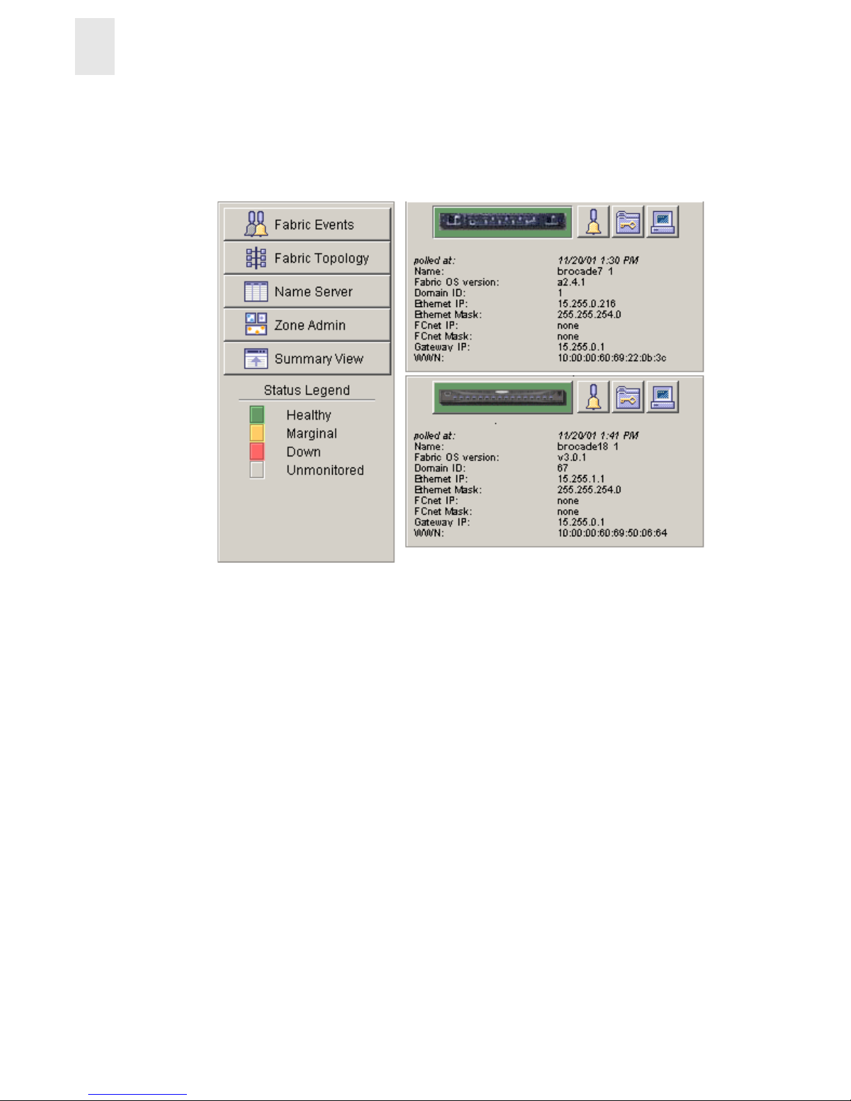
Web Tools launches, displaying Fabric View in detailed view as shown in Figure 3-1. The
Fabric View consists of two logical parts:
• Control Panel
• Switch Panel
Control Panel Switch Panel
Figure 3-1 Detailed View of Fabric View
To see the Summary view of the Fabric View, select the Summary View button on the left side of
the Fabric View.
Control Panel
Switch Panel
Page 25

Web Tools User’s Guide 3-3
Fabric View
3
Fabric View with the Summary view selected is displayed as shown in Figure 3-2.
Control Panel Switch Panel
Figure 3-2 Summary View of Fabric View
Button and Icons that appear in Fabric View
Control Panel
Switch Panel
The Control Panel (on the left side of Figure 3-1)
Fabric Events The Fabric Events View provides a running log of
events in the fabric. Select to open Fabric Events View
(for additional information, refer to the Fabric Events
View in this document).
Fabric Topology The Fabric Topology View summarizes the physical
configuration of the fabric from the perspective of the
“local domain” (the domain of the switch entered as a
URL in the Web browser). Select to open Fabric
T opo l ogy View (for additional information, refer to the
Fabric Topology View in this document) .
Name Server The Name Server Table View provid es the n ame s erv er
entries listed in the Simple Name Server database.
Select to open Name Server Table View (for additional
information, refer to the Name Server Table View in
this document).
Page 26
3-4 Web Tools User’s Guide
Fabric View
3
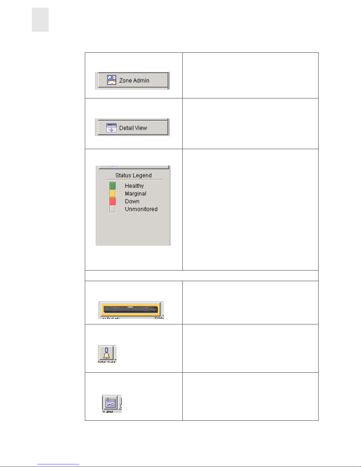
Zone Admin Select to open Zone Administration View.
Summary/Detail View Toggle to view either the Summary or Detail version of
Fabric View. The Summary version shows abbreviated
switch panels (see Figure 3-2). The default view is
Detail.
Status legend Defines meaning of colors visible in the background of
the switch icons. Each color indicates a different
operational state:
• Green Healthy
• Yellow Marginal (mix of good and faulty
readings)
• Red Down (more than two faulty
readings)
• Gray Unknown or unmonitored
If no data is available from a switch, the most recent
background color remains displayed.
Note: For all statuses that are based on errors p er time
interval, any errors will cause the status to
show faulty until the entire sample interval has
passed.
The Switch Panel (on the right side of Figure 3-1)
Switch Select to open Switch View for the switch. Each switch
type is represented by a different icon. The backgroun d
color around the icon indicates the status of the switch
(for information about this view, see Switch View).
Events Select to open Switch Events View to display the
switch events log (for information about this view, see
Switch Events View).
Admin Select to open Switch Administration View (for
information about this view, see Administrative
Interface).
Page 27
Web Tools User’s Guide 3-5
Fabric View
3
Fabric Events View
The Fabric Events View provides a running log of events for all switches in the fabric.
Accessing Fabric Topology View:
1. Launch Web Tools, displaying Fabric View.
2. Select the Fabric Events icon.
For more information, see Button and Icons that appear in Fabric View on page 3-3.
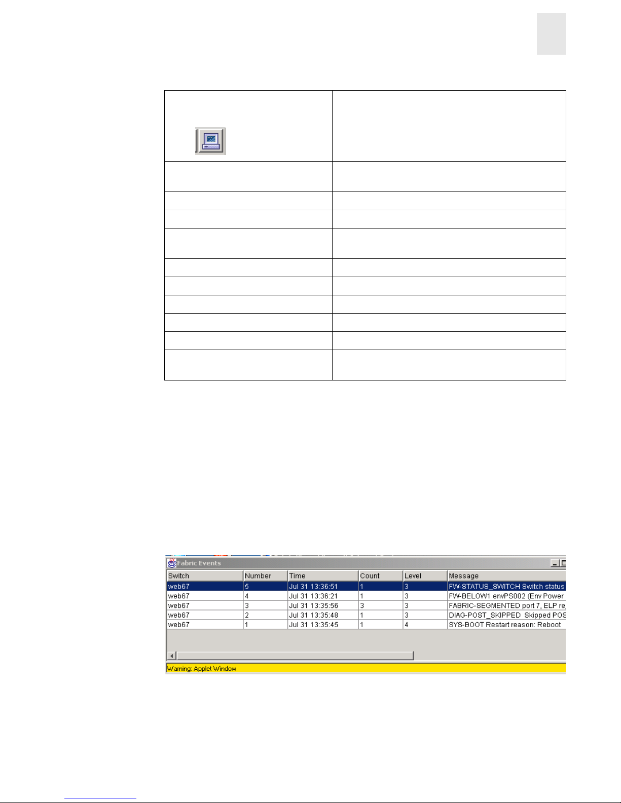
The Fabric Events window is shown in Figure 3-3.
Figure 3-3 Fabric Events View
Note: To sort the events by a particular column, select the column header. To resize a column,
drag the column divider.
Telnet Select to launch the Telnet Interface for the switch (for
information about this view, see Telnet Interface).
polled at: or unreachable since: Time of the last status check, or if currently
unavailable, the time of the last successful status check.
Name: The name of the switch.
Fabric OS version: Version of Fabric OS installed on the switch.
Domain ID: A number that uniquely identifies the switch within the
fabric.
Ethernet IP: Ethernet IP address.
Ethernet Mask: Ethernet subnetmask.
FCnet IP: Fibre channel IP address.
FCnet Mask: Fibre channel subnetmask.
Gateway IP: Gatewa y IP address.
WWN: Unique numeric identifier for the switch; assigned by
manufacturer.
Page 28

3-6 Web Tools User’s Guide
Fabric View
3
Following is a description of the columns in the Fabric Events view:
Switch Name of switch.
Num... (number) Event number for affected switch.
Time Time of event.
Count Number of consecutive occurrences of same event.
Level Severity level of event:
0 panic (switch reboots)
1 critical
2 error
3 warning
4 information
5debug
Message Description of event.
Page 29

Web Tools User’s Guide 3-7
Fabric View
3
Fabric Topology View
The Fabric Topology View summarizes the physical configuration of the fabric from the
perspective of the “local domain” (the domain of the switch entered as a URL in the Web browser).
This includes information about the “destination domains” (all other domains in the fabric) and the
paths between each destination domain and the local domain.
To access Fabric Topology View:
1. Launch Web Tools launches, displaying Fabric View.
2. Select the Fabric Topology icon.
For more information, see Button and Icons that appear in Fabric View on page 3-3.
The Fabric Topology View displays, as shown in Figure 3-4.
Figure 3-4 Fabric Topology View
Page 30

3-8 Web Tools User’s Guide
Fabric View
3
Following is a description of the fields in the Fabric Topology View.
Name Server Table View
The Name Server Table View provides the name server entries listed in the Simple Name Server
database. This includes all name server entries for the fabric, not only those that are local to the
local domain. Each row in the table represents a different device.
To access Name Server Table View:
1. Launch Web Tools, displaying Fabric View.
2. Select the Name Server Table View
For more information, see Button and Icons that appear in Fabric View on page 3-3.
The Name Server window displays, as shown in Name Server Table View on page 3-9.
View Fabric Topology from
Switch [switch name]:
Lists the switch in the domain that is assumed to be the local
domain.
There are a total of [n]
domains in the fabric.
The number of domains in the fabric.
Local domain ID: A number that uniquely identifies the local switch within the
fabric, and the name of the switch.
Domain ID: (may be
more than one)
A number that uniquely identifies the switch within the
fabric, and the name of the switch.
Active Paths: This line is followed by information about each destination
domain, including information about each of the paths
between that domain and the local domain.
Destination Domain ID: The ID of the destination domain that is described in the
lines following the ID. This information and the two lines
following it display for each destination domain in the
fabric.
Destination’s
Worldwide Name:
The WWN of the destination domain.
Number of Paths: The number of active paths between the destination domain
and the local domain.
Page 31

Web Tools User’s Guide 3-9
Fabric View
3
Figure 3-5 Name Server Table View
Note: T o sort the events by a particular column, click the column h eader . To resize a column,
drag the column divider.
The following fields are included in the Name Server Table View:
Auto Refresh Check to enable Auto Refresh or uncheck to disable.
Auto Refresh
Interval
If Auto Refresh is checked, enter the number of seconds for the refresh
interval.
Refresh Select to refresh the window immediately.
Done Select to close the window.
Page 32

3-10 Web Tools User’s Guide
Fabric View
3
The Name Server Table also includes the following columns:
Zone Administration View
Administrative privileges are required to access this view. Use Zoning to setup barriers between
different operating environments as needed for reasons of security, maintenance, or testing.
Note: The following section is intended to describe Zoning configurations when using Web T ools
specifically. For more detailed information about Zoning, see the Zoning User’s Guide.
Accessing the Zone Administration View:
1. Launch Web Tools, displaying Fabric View
2. Select the Zone Admin icon.
For more information, see Button and Icons that appear in Fabric View on page 3-3.
A prompt disp l ays requesting User Name and Password.
3. Enter User Name and Password.
4. Select OK.
Domain # The domain ID of the switch to which the device is connected.
Port # The number of the switch port to which the device is connected.
Port ID The port ID of the device (24-bit hexadecimal value).
Port Type The port type of the device (N for fabric direct attached port or NL for
fabric direct attached loop port).
Port WWN The worldwide name of the device port.
Node WWN The worldwide name of the device node.
Symbolic Name The symbolic name of the device assigned through the SCSI INQUIRY
command.
FC4 Types The Fibre Channel FC4 layer type s su pp ort ed by th e devi ce, su ch as IP
or FCP.
COS The Fibre Channel classes of service supported by the device.
Fabric Port Name The name of the fabric port in use by the device.
Port IP Address The IP address of the fabric port.
Hard Address The hard address of the fabric port.
Member of Zones The zones to which this device belongs. This column does not update
when the table is refreshed. To view updated zoning information, close
and reopen the Name Server Table.
Page 33

Web Tools User’s Guide 3-11
Fabric View
3
The Zoning Selection menu displays, as shown in Figure 3-6.
Note: For information specific to Qu ickLoop to b e available, the Qu ickLoop s witch must be
the local domain.
Figure 3-6 Zoning Selecti on View
When administering Zoning, the following steps are recommended:
1. Define zone aliases to establish groupings.
2. Add zone members.
3. Place zones into one or more zone configurations.
4. Enable one of the zone configurations (only one can be enabled at a time).
There are three separate methods for adding members to a zone
• A Member
• A Zone
• A Configuration
For more information about configuring Zoning, see the Zoning User’s Guide.
A description of each of the zoning schemes is shown in Table 3-1.
Page 34

3-12 Web Tools User’s Guide
Fabric View
3
Note: If a switch or device is added or removed from the network, it is necessary to save the
changes and relaunch the Zone Administration view for the changes to take effect.
Switch/Port Level Zoning
Upon selecting the Switch/Port Lev el Zoni ng but ton from th e Zoning S election men u and se lecting
OK, the Switch/Port Level Zoning menu with the Port Alias tab displayed as shown in Figure 3-7.
Following is a list of the tabs provided in the Switch/Port Level Zoning menu:
• Port Alias
• Port Zone
• Quick Loop
• Port Fabric Assist
• Port Config
Port Alias Tab
The Port Alias tab shows only Domain/Ports that are in the fabric. This tab is used to configure
zones that consist only of Domain/Ports and aliases that contain only Domain/Ports.The Port Alias
tab is displayed as shown in Figure 3-7
Table 3-1 Zoning Schemes
Switch/Port Level
Zoning
All alias, zoning and configuration file operations must be on ports.
Aliases, zones and configuration files which have objects other than
ports cannot be selected or operated on.
WWN Level Zoning All aliases, zoning and configuration file operations must be on
WWNs. Aliases, zones and configuration files which have objects
other than WWNs cannot be selected or operated on.
AL_PA Level Zoning All aliases, zoning and configuration file operations must be on
AL_PA in a QuickLoop. Aliases, zones and configuration files which
have objects other than AL_PAs in a QuickLoop cannot be selected or
operated on.
Mixed Level Zoning In this mode, any object can be selected to be a member of a zone,
alias or configuration file. This mode doesn’t allow specification of a
LUN.
Page 35

Web Tools User’s Guide 3-13
Fabric View
3
.
Figure 3-7 Port Alias tab of the Switch/Port Level Zoning menu
Following is a description of the fields on the Port Alias tab:
Alias Name Select an existing alias name to be modified.
Create Alias Select to create a new alias. A new alias dialog displays. Enter a new
alias name that is unique. The new alias name cannot contain spaces.
Delete Alias Select to delete the alias selected in the Alias Name field. Deleting an
alias automatically removes it from all zones.
Rename Alias Select to rename the alias selected in the Alias Name field. A dialog
displays in which you can edit the alias name. Renaming an alias
automatically renames it in all zones.
Member Selection List This field contains a list of potential alias members, incl udin g
switches, ports, WWNs, and QuickLoop AL_PAs, and Fabric Assists.
Add Mem Select to add the item selected in the Member Selection List to the
Alias Members list. You can add individual ports or an entire switch.
If a switch is added, all ports on the switch are added. To add a device
WWN, select either a node WWN (folder icon) or port WWN (blue
circle icon) from the WWN sub-tree.
Remove Mem Select to remove the member selected from the Alias Name Member s
Selection list.
Page 36

3-14 Web Tools User’s Guide
Fabric View
3
Alias Members This field lists the members of the alias selected in the Alias Name
field. The name of this list depends on the name of the selected alias.
If no alias is selected, the name displays as “Null Members”.
Search Mem Select to search for a Switch name, WWN, Alias, Zone, QuickLoop in
the Member Selection List based on the type of objects displayed in
that list.
Add FA Host Click to add an FA Host that currently is not part of the fabric.
Add Sw/Port Select to add a switch/port combinatio n that currently is not part of t he
fabric.
Add Switch/Port/Host Click to add a switch/port/host comb ination that currently is not part
of the fabric.
Ref Zone Select to refresh the local zoning data base copied from the switch.
This button automatically flashes red/gray if the fabric zoning data is
changed by another client.
A/D WWN Select to add or delete a WWN to or from all the Aliases, Zones
defined.
Rpl WWN Select to replace a WWN with another one in all Aliases, Zones
defined.
OK Ap plies the changes to the switch and exits the frame.
Apply Select to apply all changes made since the Zone Administration View
was opened, including changes made on other tabs in the view.
Changes cannot be cancelled once applied.
Close Select to exit the frame without making any changes to the switch.
Clr All S elect to clear all Aliases, Zones, Configs locally on the switch.
Page 37

Web Tools User’s Guide 3-15
Fabric View
3
Port Zone Tab
Use the Port Zone tab to specify which ports on a switch are to be in the selected zone and to create
and manage zones. A zone can have one or multiple members, and can include switches, ports,
WWNs, aliases, and QuickLoop AL_PAs. The Port Zone tab is shown in Figure 3-8.
Figure 3-8 The Port Zone tab of the Switch/Port Level Zoning menu
Following is a description of the fields on the Port Zone tab.
Zone Name To modify an existing zone, select a zone name.
Create Zone Select to create a new zone. A dialog displays in which you can enter the
name of the new zone. All names must be unique and contain no spaces.
Delete Zone Select to delete the zone selected in the Zone Name field. Deleting a zone
automatically removes it from all zone configuration s.
Rename Zone Select to edit the name of the zone selected in the Zone Name field. A
dialog displays in which you can edit the name of the zone.
Search Mem Select to search the list of potential zone members.
Member Selection
List
A list of potential zone members, including switches, ports, WWNs,
aliases, and QuickLoop AL_PAs, and Fabric Assists.
Page 38

3-16 Web Tools User’s Guide
Fabric View
3
Add Mem Select to add the member selected in the Member Selection List to the
Zone Members list. If an entire switch is selected, all ports on the switch
are added to the zone. You can also select individual port s. To add a device
WWN, select either a node WWN (folder icon) or port WWN (blue circle
icon) from the WWNs sub-tree. To add an alias to the zone, select it from
the Aliases sub-tree (the alias must already exist).
Remove Mem Select to remove the selected member from the Zone name Members list.
[Zone name]
Members
This field lists members of the zone selected in the Zone Name field. The
name of this list depends on the name of the selected zone. If no zone is
selected, the name displays as “null Members”.
Ref Zone Click to refresh the local zoning data base copied from the switch. This
button automatically flashes red/gray if the fabric zoning data is changed
by another client.
A/D WWN Click to add or delete a WWN to or from all the Aliases, Zones defined.
Rpl WWN Click to replace a WWN with another one in all Aliases, Zones defined.
OK Applies the changes to the switch and exits the frame.
Apply Click to apply all changes made since the Zone Administration View was
opened, including changes made on other tabs in the view. Changes cannot
be cancelled once they are applied.
Close Click to exit the window with out m a ki ng any changes to the switch.
Clr All Click to clear all Aliases, Zones, Configs locally on the switch.
Page 39

Web Tools User’s Guide 3-17
Fabric View
3
QuickLoop Tab
You can use the QuickLoop tab to create and manage QuickLoops if used in conjunction with
Zoning. For information on managing the QuickLoop feature separately, see QuickLoop Tab on
page 4-50 in this document.
The QuickLoop tab is shown in Figure 3-9.
Figure 3-9 The QuickLoop tab of the Switch/Port Level Zoning menu
Following is a description of the fields on the QuickLoop tab.
QuickLoop Name To modify an existing QuickLoop, select a QuickLoop name.
Create Qloop Click to create a new QuickLoop. A dialog di sp la ys i n which you can
enter the name of the new QuickLoop. All names must be unique and
contain no spaces.
Delete Qloop Click to delete the QuickLoop selected in the QuickLoop Name field.
Deleting a QuickLoop automatically removes it from all aliases,
zones, and zone configurations, including the associated AL_PAs.
Rename Qloop Click to edit the name of the QuickLoop selected in the QuickLoop
Name field. A dialog displays in which you can edit the name of the
QuickLoop.
Switch Selection List A list of the switches available to add to the QuickLoop.
Page 40

3-18 Web Tools User’s Guide
Fabric View
3
Search Mem Click to search for a Switch name, WWN, Alias, Zone, QuickLoop in
the Switch Selection List based on the type of objects displayed in that
list.
Add Mem Click to add the switch selected in the Switch Selection List to the
QuickLoop Members list.
Remove Mem Click to remove the selected member from the QuickLoop Name list.
[QuickLoop name]
Members
A list of the members of the QuickLoop currently selected in the
QuickLoop Name field. The name of this list depends on the name of
the selected QuickLoop. If no QuickLoop is selected, the name
displays as “null Members”.
Apply Click to apply all changes made since the Zone Administration View
was opened, including changes made on other tabs in the view.
Changes cannot be cancelled once they are applied.
Close Click to cancel all changes since the changes were last applied and to
exit Zone Administration. Changes cannot be cancelled once they are
applied.
Clr All C lick to apply all changes made since the Zone Administration View
was opened and to exit the Zone Admini stration View.
Page 41

Web Tools User’s Guide 3-19
Fabric View
3
Port Fabric Assist Tab
Use the Port Fabric Assist tab to create and manage Fabric Assists. A QuickLoop license is
required to use this tab. The Port Fabric Assist tab is shown in Figure 3-11.
Figure 3-10 The Port Fabric Assist tab of the Switch/Port Level Zoning menu
Following is a description of the fields on the Port Fabric Assist tab.
FA Name Select the existing Port Fabric Assist name to be modified.
Create FA Click to create a new Port Fabric Assist name. A dialog
displays. Enter the name of the new Port Fabric Assist. All
names must be unique and contain no spaces.
Delete FA Click to delete the Port Fabric Assist selected in the FA Name
field. Deleting a Port Fabric Assist automatically removes it
from all aliases, zones, and zone configurations, including the
associated AL_PAs.
Rename FA Click to edit the name of the Port Fabric Assist selected in the
FA Name field.
Member Selection List This field displays a list of members available to add to the
Port Fabric Assist list.
Page 42

3-20 Web Tools User’s Guide
Fabric View
3
Add FA Host Click to add the selected item as a host to the Port Fabric Assist
name list. Only a domain port or a WWN can be added as a
host.
Add Mem Click to add the member selected in the Member Selection List
to the Port Fabric Assist name list.
Remove Mem Click to remove the selected member from the Port Fabric
Assist name list.
Search Mem Click to search for a Switch name, WWN, Alias, Zone,
QuickLoop, FA Zone in the Member Selection List based on
the type of objects displayed in that list.
Add Switch/Port Click to add a switch/port combination that is not currently part
of the fabri c.
Add Switch/Port/Host Click to add a switch/port/h ost combination that currently is
not part of the fabric.
[Fabric Assist name]
Members
This field displays a list of the members that belong to the Port
Fabric Assist currently selected in the FA Name field. The
name of this list depends on the name of the Port Fabric Assist
selected. If no Port Fabric Assist is selected, the name displays
as “null Members”.
Ref Zone Click to refresh the local zoning data base copied from the
switch. This button automatically flashes red/gray if the fabric
zoning data is changed by another client.
A/D WWN Click to add or delete a WWN to or from all the Aliases,
Zones, FA Zones defined.
Rpl WWN Click to replace a WWN with another one in all Aliases, Zones,
FA Zones defined.
OK Click to apply changes made in this window and exit the
window.
Apply Click to apply all changes made including changes made on
other tabs in the view. Changes in this window cannot be
cancelled once they are applied.
Close Click to exit the window without making any changes to the
switch.
Clr All Click to clear all Aliases, Zones, Configs, FA Zones locally on
the switch.
Page 43

Web Tools User’s Guide 3-21
Fabric View
3
Port Config Tab
Use the Port Config tab to create and manage zone configurations. Zone confi gu rati ons are us ed to
enable or disable a group of zones at the same time. The Port Config tab is shown in Figure 3-11.
Figure 3-11 The Port Config tab of the Switch/Port Level Zoning menu
Following is a description of the fields and buttons that appear on the Port Config tab.
Cfg Name Select an existing configuration to modify.
Create Cfg Click to create a new configuration. A dialog displays. Enter the name of
the new configuration. All names must be unique and contain no spaces.
Delete Cfg Click to delete the configuration selected in the Cfg Name field.
Rename Cfg Click to edit the name of the configuration selected in the Cfg Name field.
Zone/QLoop
Selection List
This field provides a list of the zones and QuickLoops available to add to
the configuration.
Add Mem Click to add the switch selected in the Zone/QLoop Selection List to the
Config Members list.
Remove Mem Click to remove the selected member from the Config Members list.
Search Mem Click to search for a Switch name, WWN, Alias, Zone, QuickLoop in the
Member Selection List based on the type of objects displayed in that list.
Page 44

3-22 Web Tools User’s Guide
Fabric View
3
Zoning Configuration Analysis screen
The Zoning Configuratio n Analys i s scr een di s plays a s umm ary o f t he sa ved con fi gur atio n an d
attempts to point out some of the zoning conflicts before applying the changes to the switch.
Some of the potential errors it might catch are:
• Ports/WWNs/Devices that are part of the selected configuration, but not part of the
fabric.
• Zones with only a single member.
The Zoning Configuration Analyze screen is shown in Figure 3-12.
Config Members The members of the configuration selected in the Cfg Name field. The
name of this list depends on the selection. Only one configuration can be
enabled at a time; if none are enabled, zoning is not active in the fabric.
Enable Config Check to enable the configuration selected in the Cfg Name field, or
uncheck to disable it.
Disable Zoning Check to disable zoning.
Analyze Config Analyzes the configuration that is selected along with it’s member zones
and aliases. A zoning configuration error screen (See Figure 3-11)
appears in the event of a conflict.
Refresh Fabric Click to refresh the fabric view with the latest Domain/Port and WWN
changes.
Ref Zone Click to refresh the local zoning data base copied from the swit ch. This
button automatically flashes red/gray if the fabric zoning data is changed
by another client.
A/D WWN Click to add or delete a WWN to or from all the Aliases, Zones defined.
Rpl WWN Click to replace a WWN with another one in all Aliases, Zonesdefined.
Apply Click to apply all changes made since the Zone Administration View was
opened, including changes made on other tabs in the view. Changes
cannot be cancelled once they are applied.
Close Click to exit the window without making any changes to the switch.
Ok Applies the changes to the switch and exits the window.
Clr All Click to clear all Aliases, Zones, Configs locally on the window.
Page 45

Web Tools User’s Guide 3-23
Fabric View
3
Figure 3-12 Zoning Configuration Analysis screen
WWN Level Zoning
With WWN Zoning, only World Wide Names are displayed on the tabs. This wind ow is used to
configure aliases, zones and configuration files. After selecting the WWN Level Zoning button
from the Zoning Selection menu and clicking OK, the WWN Level Zoning menu displays.
Following is a list of the tabs provided in the WWN Level Zoning menu:
• WWN Alia s
• WWN Zone
• Quick Loop
• WWN Fabric Assist
• WWN Config
Page 46

3-24 Web Tools User’s Guide
Fabric View
3
WWN Aliases
Use the WWN Alias tab to configure WWN Aliases.
Figure 3-13 shows the WWN Alias tab.
Figure 3-13 WWN Alias tab of the WWN Level Zoning menu
Following is a description of the fields on the WWN Alias tab.
Alias Name Select an existing alias to modify.
Create Alias Click to create a new alias. A dialog displays in which you can enter
the name of the new alias. All names must be unique and contain no
spaces.
Delete Alias Click to delete the alias select ed in the Alias Name field. Deleting an
alias automatically removes it from all zones.
Rename Alias Click to rename the alias selected in the Alias Name field. A dialog
displays in which you can edit the alias name. Renaming an alias
automatically renames it in all zones.
Member Selection List A list of potential alias members, including switches, ports, WWNs,
and QuickLoop AL_PAs, and Fabric Assists.
Page 47

Web Tools User’s Guide 3-25
Fabric View
3
Alias Members This field lists the members of the alias selected in the Alias Name
field. The name of this list depends on the name of the selected alias.
If no alias is selected, the name displays as “Null Members”.
Search Mem Click to search for a Switch name, WWN, Alias, Zone, Quic kLoop, in
the Member Selection List based on the type of objects displayed in
that list.
Add FA Host Click to add the selected item as a host to the Members list. Only a
domain port or a WWN can be added as a host.
Add Mem Click to add the item selected in the Member Selection List to the
Alias Members list. You can add individual ports or an entire switch.
If a switch is added, all ports on the switch are added. To add a device
WWN, select either a node WWN (folder icon) or port WWN (blue
circle icon) from the WWN sub-tree.
Remove Mem Click to remove the selected member from the Configuration name
list.
Add WWN Click to add a WWN that currently is not part of the Fabric.
Ref Zone Click to refresh the local zoning data base copied from the switch.
This button automatically flashes red/gray if the fabric zoning data is
changed by another client.
A/D WWN Click to add or delete a WWN to or from all the aliases, zones
defined.
Rpl WWN Click to replace WWN with another one in all aliases, zones defined.
OK C lick to apply the changes to the switch and exit the window.
Apply Click to apply the changes to the switch.
Close Click to exit the window without making any changes to the switch.
Clr All C lick to clear all aliases, zones, configs locally on the switch.
Page 48

3-26 Web Tools User’s Guide
Fabric View
3
WWN Zone
Use the WWN Zone tab to specify the members of the WWN Zone. In this window, only switches
and WWN are available to be selected as members of the zone.
The WWN Zone tab is shown in Figure 3-14.
Figure 3-14 WWN Zone tab of the WWN Level Zoning menu
Following is a description of the fields on the WWN Zone tab.
Zone Name Select an existing zone member to modify.
Create Zone Click to create a new zone member.
Delete Zone Click to delete a zone member.
Rename Zone Click to rename a zone member.
Member Selection List This field displays a list of potential zone members, including
switches, ports, WWNs, and QuickLoop AL_PAs, and Fabric Assists.
Zone Members This field lists the zone members selected in the Zone Name field.
The name on this list depends on the name of the selected zone
member. If a name is not selected, the name displays as “null
Members”.
Page 49

Web Tools User’s Guide 3-27
Fabric View
3
Quick Loop
You can use the QuickLoop tab to create and manage QuickLoops if used in conjunction with
Zoning. For information on managing the QuickLoop feature separately, see Loop Tab in this
document.
The Quick Loop tab is shown in Figure 3-15.
Search Mem Click to search for a Switch name, WWN, Alias, Zone, Quic kLoop, in
the Member Selection List based on the type of objects displayed in
that list.
Add Mem Click to add a member from the Member Selection list into the Zone
Member contents.
Remove Mem Click to remove a member from the Zone Member list.
Add WWN Click to add a WWN that is not currently part of the Fabric.
Ref Zone Click to refresh the local zoning data base copied from the switch.
This button automatically flashes red/gray if the fabric zoning data is
changed by another client.
A/D WWN Click to add or delete a WWN to or from all the aliases, zones defined
Rpl WWN Click to replace WWN with another one in all aliases, zones defined.
OK C lick to apply the changes to the switch and exit the switch.
Apply Click to apply the changes to the switch.
Close Click to exit the window without making any changes to the switch.
Clr All C lick to clear all aliases, zones, configs locally on the switch.
Page 50

3-28 Web Tools User’s Guide
Fabric View
3
Figure 3-15 QuickLoop tab of the WWN Level Zoning menu
Following is a description of the fields on the QuickLoop tab.
QuickLoop Name Select an existing QuickLoop member to modify.
Create Qloop Click to create a new Quickloop member.
Delete Qloop Click to delete a Quickloop member.
Rename Qloop Click to rename a Quickloop member.
Switch Selection List This field displays a list of potential QuickLoop members, including
switches, ports, WWNs, and QuickLoop AL_PAs, and Fabric Assist.
QuickLoop Members This field contains a list of the zone members selected in the
QuickLoop Name field. The name on thi s list depends on the nam e of
the selected QuickLoop member. If a name is not selected, the name
displays as “null Members”.
Search Mem Click to search for a Switch name, WWN, Alias, Zone, QuickLoop in
the Member Selection List based on the type of objects displayed in
that list.
Add Mem Click to add a member from the member selection list into the
QuickLoop member contents.
Page 51

Web Tools User’s Guide 3-29
Fabric View
3
WWN Fabric Assist
Use the WWN Fabric Assist tab to create and manage WWN Fabric Assists. A QuickLoop license
is required to use this tab. The WWN Fabric Assist tab is shown in Figure 3-17.
Figure 3-16 WWN Fabric Assist tab of the WWN Level Zoning Menu
Remove Mem Click to remove a member from the QuickLoop m ember list when
selected.
Ref Zone Click to refresh the local zoning data base copied from the switch.
This button automatically flashes red/gray if the fabric zoning data is
changed by another client.
A/D WWN Click to add or delete a WWN to or from all the aliases, zones
defined.
Rpl WWN Click to replace WWN with another one in all aliases, zones defined.
OK C lick to apply the changes to the switch and exit the switch.
Apply Click to apply the changes to the switch.
Close Click to exit the window without making any changes to the switch.
Page 52

3-30 Web Tools User’s Guide
Fabric View
3
Following is a description of the fields on the WWN Fabric Assist tab.
FA Name Select an existing WWN F abric Assist name to modify.
Create FA Click to create a new WWN Fabric Assist. A dialog displays.
Enter the name of the new WWN Fabric Assist. All names
must be unique and contain no spaces.
Delete FA Click to delete the WWN Fabric Assist selected in the FA
Name field. Deleting a WWN Fabric Assist automatically
removes it from all aliases, zones, and zone configurations,
including the associated AL_PAs.
Rename FA Click to edit the name of the WWN Fabric Assist selected in
the FA Name field.
Member Selection List This field displays a list of members available to add to the
WWN Fabric Assist.
Add FA Host Click to add the selected item as a host to the WWN Fabric
Assist name list. Only a domain port or a WWN can be added
as a host.
Add Mem Click to add the member selected in the Member Selection List
to the WWN Fabric Assist name list.
Remove Mem Click to remove the selected member from the WWN Fabric
Assist name list.
Search Mem Click to search for a Switch name, WWN, Alias, Zone,
QuickLoop, FA Zone in the Member Selection List based on
the type of objects displayed in that list.
[WWN Fabric Assist name]
FA Members
A list of the members that belong to the WWN Fabric Assist
currently selected in the FA Name field. The name of this list
depends on the name of the WWN Fabric Assist selected. If no
WWN Fabric Assist is selected, the name displays as “null
Members”.
Ref Zone Click to refresh the local zoning data base copy from the
switch. This button would automatically flash red/gray if the
fabric zoning data is changed by another client.
Add WWN Click to add a WW N that is not currently part of the Fabric.
Add WWN Host Click to add a WWN Host that is not currently part of the
Fabric.
A/D WWN Click to add/delete a WWN to/from all the Aliases, Zones, FA
Zones defined.
Rpl WWN Click to replace a WWN with another one in all Aliases, Zones,
FA Zones defined.
Page 53

Web Tools User’s Guide 3-31
Fabric View
3
WWN Config
Use the WWN Config tab to specify which zones comprise a WWN Zone Configuration file. The
WWN Config tab is shown in Figure 3-17.
Figure 3-17 WWN Config tab of the WWN Level Zoning menu
Following is a description of the fields on the WWN Config tab.
OK Select OK to the changes to the switch and exit the window.
Apply Click to apply all changes made including changes made on
other tabs in the view. Changes cannot be cancelled once they
are applied.
Close Click to exit the window without making any changes to the
switch.
Clr All Click to clear all Aliases, Zones, Configs, FA Zones locally on
the client.
Cfg Name Select to modify an existing WWN configuration name to be
modified.
Create Cfg Click to create a new WWN configuration.
Delete Cfg Click to delete a W WN configuration.
Rename Cfg Click to rename a WWN configuration.
Page 54

3-32 Web Tools User’s Guide
Fabric View
3
Zone/QLoop Selection List This field displays a list of Zone and QuickLoop members
available to add to the WWN configuration.
Add Mem Click to add a member from the config members list into the
zone selection list.
Remove Mem Click to remove a member from the zone selection list into the
Config Member list.
Search Mem Click to search for a Switch name, WWN, Alias, Zone, Qloop
in the Zone Selection List based on the type of objects
displayed in that list.
Config Members This field display s a list o f the me mbers that belong to the
WWN Configuration currently selected in the Cfg Name field.
The name of this list depends on the name of the WWN
configuration selected. If WWN configuration is not selected,
the name displays as “null Members”.
Analyze Config Click to analyze the configuration that is selected along with its
member zones and aliases. A zoning error screen (see
Figure 3-12) appears in the event of a conflict.
Enable Config If this option is checked, and the Apply button pressed, the
selected configuration would be used for zoning the fabric.
Disable Config Click the Disable Config radio button to disable the selected
WWN Zone configuration.
Refresh Fabric Click to refresh the fabric view with the latest Domain/Port and
WWN changes.
Ref Zone Click to refresh the local zoning data base copied from the
switch. This button automatically flashes red/gray if the fabric
zoning data is changed by another client.
A/D WWN Click to add/delete a WWN to/from all the Aliases, Zones
defined.
Rpl WWN Click to replace a WWN with another one in all Aliases, Zones
defined.
OK Applies the changes to the switch and exits the switch.
Apply Click to apply all changes made including changes made on
other tabs in the view. Changes cannot be cancelled once they
are applied.
Close Click to exit the window without making any changes to the
switch.
Clr All Click to clear all Aliases, Zones, Configs locally on the switch.
Page 55

Web Tools User’s Guide 3-33
Fabric View
3
AL_PA Level Zoning
AL_PA Level Zoning is a replacement for QuickLoop Zoning. With AL_PA Level Zoning, only
members of a QuickLoop can be a member of the zone. Zone members are specified through their
AL_PA. Upon selecting the AL_PA Level Zoning button from the Zoning Selection window and
clicking OK, the AL_PA Level Zoning menu with the AL_PA Device Alias tab displays.
Figure 3-18 shows a typical AL_PA Device Alias tab of the AL_PA Zoning window.
Following is a list of the tabs provided in the AL_PA Level Zoning menu:
• Device Alias
• Device Zone
• QuickLoop
• Device Config
AL_PA Device Alias
Use the AL_PA Device Alias tab to create and manage QuickLoop configurations. QuickLoop
configurations are used to enable or disable a group of zones at the same time.
The AL_PA Device Alias tab is shown in Figure 3-18.
Figure 3-18 AL_PA Device Alias tab of the AL_PA Level Zoning menu
Page 56

3-34 Web Tools User’s Guide
Fabric View
3
Following is a description of the fields on the AL_PA Device Alias tab.
Alias Name Select an existing alias name to modify.
Create Alias Click to create a new alias. A dialog displays. Enter the name of the
new alias. All names must be unique and contain no spaces.
Delete Alias Click to delete the alias select ed in the Alias Name field. Deleting an
alias automatically removes it from all zones.
Rename Alias Click to rename the alias selected in the Alias Name field. A dialog
displays in which you can edit the alias name. Renaming an alias
automatically renames it in all zones.
Member Selection List This field displays a list of potential alias m embers, including
switches, ports, WWNs, and QuickLoop AL_PAs, and Fabric Assists.
Alias Members This field lists the members of the alias selected in the Alias Name
field. The name of this list depends on the name of the selected alias.
If no alias is selected, the name displays as “Null Members.'
Search Mem Click to search for a Switch name, WWN, Alias, Zone, Qloop in the
Member Selection List based on the type of objects displayed in that
list.
Add FA Host Click to add the selected item as a host to the Members list. Only a
domain port or a WWN can be added as a host.
Add Mem Click to add a member from the Member Selection List to the Alias
Members list.
Add Device Click to allow adding a device that currently is not part of the fabric.
Remove Mem Click to remove the selected member from the Alias Members list.
Ref Zone Click to refresh the local zoning data base copied from the switch.
This button automatically flashes red/gray if the fabric zoning data is
changed by another client.
A/D WWN Click to add or delete a WWN to or from all the aliases, zones
defined.
Rpl WWN Click to replace WWN with another one in all aliases, zones defined.
OK C lick to apply the changes to the switch and exit the switch.
Apply Click to apply the changes to the switch.
Close Click to exit the window without making any changes to the switch.
Clr All C lick to clear all aliases, zones, configs locally on the switch.
Page 57

Web Tools User’s Guide 3-35
Fabric View
3
AL_PA Device Zone
Use the AL_PA Device Zone tab to select members of a device zone. Members are specified by
their AL_PA. The AL_PA Device Zone tab is shown in Figure 3-19.
Figure 3-19 AL_PA Device Zone tab of the AL_PA Level Zoning menu
Following is a description of the fields on the AL_PA Device Zone tab.
Zone Name Select an existing zone member to modify.
Create Zone Click to create a new zone member.
Delete Zone Click to delete a zone member.
Rename Zone Click to rename a zone member.
Member Selection List This field displays a list of potential zone members, incl uding
switches, ports, WWNs, and QuickLoop AL_PAs, and Fabric Assist.
Zone Members This field lists the zone members selected in the Zone Name field.
The name on this list depends on the name of the selected zone
member. If a name is not selected, the name displays as “null
Members.”
Search Mem Click to search for a Switch name, WWN, Alias, Zone, Quic kLoop, in
the Member Selection List based on the type of objects displayed in
that list.
Add Device Click to add a device that currently is not part of the Fabric.
Page 58

3-36 Web Tools User’s Guide
Fabric View
3
Quick Loop
Use the Quick Loop tab to create and manage Quick Loops. For information on managing the
Quick Loop feature separately, see Loop Tab in this document. The Quick Loop tab is shown in
Figure 3-20.
Figure 3-20 Quick Loop tab of the AL_PA Level Zoning menu
Add Mem Click to add a member from the member selection list into the Zone
Members list.
Remove Mem Click to remove a member from the Zone Member List when selected.
Ref Zone Click to refresh the local zoning data base copied from the switch.
This button automatically flashes red/gray if the fabric zoning data is
changed by another client.
A/D WWN Click to add or delete a WWN to or from all the aliases, zones defined
Rpl WWN Click to replace WWN with another one in all aliases, zones defined.
OK C lick to apply the changes to the switch and exit the switch.
Apply Click to apply the changes to the switch.
Close Click to exit the window without making any changes to the switch.
Clr All C lick to clear all aliases, zones, configs locally on the switch.
Page 59

Web Tools User’s Guide 3-37
Fabric View
3
Following is a description of the fields on the Quick Loop tab.
QuickLoop Name Select an existing QuickLoop member name to modify.
Create Qloop Click to create a new Quickloop member.
Delete Qloop Click to delete a Quickloop member.
Rename Qloop Click to rename a Quickloop member.
Switch Selection List This field displays a list of potential QuickLoop members, including
switches, ports, WWNs, and QuickLoop AL_PAs, and Fabric Assists.
QuickLoop Members This field displays a list of the zone members selected in the
QuickLoop Name field. The name on thi s list depends on the nam e of
the selected QuickLoop member. If a name is not selected, the name
displays as “null Members.”
Search Mem Click to search for a Switch name, WWN, Alias, Zone, Quic kLoop, in
the Member Selection List based on the type of objects displayed in
that list.
Add Mem Click to add a member from the member selection list into the
QuickLoop member contents.
Remove Mem Click to remove a member from the QuickLoop m ember list when
selected.
Ref Zone Click to refresh the local zoning data base copied from the switch.
This button automatically flashes red/gray if the fabric zoning data is
changed by another client.
A/D WWN Click to add or delete a WWN to or from all the aliases, zones
defined.
Rpl WWN Click to replace WWN with another one in all aliases, zones defined.
OK C lick to apply the changes to the switch and exit the switch.
Apply Click to apply the changes to the switch.
Close Click to exit the window without making any changes to the switch.
Page 60

3-38 Web Tools User’s Guide
Fabric View
3
AL_PA Device Config
Use the AL_PA Device Config tab to specify the Device Zone that belongs to the Device Zone
Configuration file. All members of this configuration file must be Zones consisting entirely of
AL_PAs in a QuickLoop. The AL_PA Device Config tab is shown in Figure 3-21.
Figure 3-21 AL_PA Device Config tab of the AL_PA Level Zoning menu
Following is a description of the fields on the AL_PA Device Config tab.
Cfg Name Select an existin g AL_PA Configuration name to modify.
Create Cfg Click to create a new AL_PA configuration.
Delete Cfg Click to delete a AL_PA configuration.
Rename Cfg Click to rename a AL_PA configuration.
Zone/QLoop Selection List A list of Zone/QuickLoop members available to add to the
AL_PA configuration.
Add Mem Click to add a member from the Zone Selection List into the
Configuration Member List.
Remove Mem Click to remove a member from the Zone Selection List into
the Configuration Member List.
Search Mem Click to search for a Switch name, WWN, Alias, Zone, Qloop
in the Member Selection List based on the type of objects
displayed in that list.
Page 61

Web Tools User’s Guide 3-39
Fabric View
3
AL_PA Config Mem bers
name
This field displays a list of the members that belong to the
AL_P A Configuration currently selected in the Cfg Name field.
The name of this list depends on the name of the AL_PA
configuration selected. If a AL_PA configuration is not
selected, the name displays as “null Members”.
Analyze Config Click to analyze the configuration that is selected along with
it’s member zones and aliases, and comes up with a zoning
error screen (See Figure 3-13) in the event of a conflict.
Enable Config Select this option and press the Apply button to enable the
selected config for zoning the fabric.
Disable Zoning Select this option and press the Apply button to disable the
selected config for zoning the fabric.
Refresh Fabric Click to refresh the fabric view with the latest Domain/Port and
WWN changes.
Ref Zone Click to refresh the local zoning data base copied from the
switch. This button automatically flashes red/gray if the fabric
zoning data is changed by another client.
A/D WWN Click to add or delete a WWN to or from all the Aliases, Zones
defined.
Rpl WWN Click to replace a WWN with another one in all Aliases, Zones,
defined.
OK Applies the changes to the switch and exits the switch.
Apply Click to apply all changes made including changes made on
other tabs in the view. Changes cannot be cancelled once they
are applied.
Close Click to exit the window without making any changes to the
switch.
Clr All Click to clear all Aliases, Zones, Configs locally on the switch.
Page 62

3-40 Web Tools User’s Guide
Fabric View
3
Mixed Level Zoning
Mixed Level Zoning is provided for backward compatibility of pre 3.0 zones. After selecting the
Mixed Level Zoning button from the Zoning Selection window and clicking OK, the Mixed Level
Zoning window with the Alias tab is displayed as shown in Figure 3-22.
Following is a list of the tabs provided in the Mixed Level Zoning menu:
• Alias
• Zone
• QuickLoop
• Fabric Assist
• Config
Alias
Use the Alias tab to set up mixed aliases. The Alias tab is shown in Figure 3-22.
Figure 3-22 Alias tab of the Mixed Level Zoning menu
Page 63

Web Tools User’s Guide 3-41
Fabric View
3
Following is a description of the fields on the Alias tab.
Alias Name Select an existing alias to modify.
Create Alias Click to create a new alias. A dialog displays.Enter the name of the
new alias. All names must be unique and contain no spaces.
Delete Alias Click to delete the alias sel ected in the Al ias Name field. Deleting an
alias automatically removes it from all zones.
Rename Alias Click to rename the alias selected in the Alias Name field. A dialog
displays in which you can edit the alias name. Renaming an alias
automatically renames it in all zones.
Member Selection List This field displays a of potential alias members, including switches,
ports, WWNs, and QuickLoop AL_PAs, and Fabric Assists.
Alias Members This field lists the members of the alias selected in the Alias Name
field. The name of this list depends on the name of the selected alias.
If no alias is selected, the name displays as “Null Members.”
Search Mem Click to search for a Switch name, WWN, Alias, Zone, Qloop in the
Member Selection List based on the type of objects displayed in that
list.
Add FA Host Click to add the selected item as a host to the Members list. Only a
domain port or a WWN can be added as a host.
Add Mem Click to add a member from the Member Selection List to the Alias
Members list.
Add Other Click to add a switch/port, WWN or a device that currently is not part
of the fabric.
Add Other Host Click to add other Host that is not currently part of the fabric.
Remove Mem Click to remove the selected member from the Alias Members list.
Ref Zone Click to refresh the local zoning data base copied from the switch.
This button automatically flashes red/gray if the fabric zoning data is
changed by another client.
A/D WWN Click to add or delete a WWN to or from all the aliases, zones defined
Rpl WWN Click to replace WWN with another one in all aliases, zones defined.
OK C lick to apply the changes to the switch and exit the window.
Apply Click to apply the changes to the switch.
Close Click to exit the window without making any changes to the switch.
Clr All C lick to clear all aliases, zones, configs locally on the switch.
Page 64

3-42 Web Tools User’s Guide
Fabric View
3
Zone
Use the Zone tab to specify the member of a mixed zone. Mixed zone members can be AL_PAs,
ports and WWNs. The Zone tab is shown in Figure 3-23.
Figure 3-23 Zone tab of the Mixed Level Zoning menu
Following is a description of the fields on the Zone tab.
Zone Name Select an existing zone member to modify.
Create Zone Click to create a new zone member.
Delete Zone Click to delete a zone member.
Rename Zone Click to rename a zone member.
Member Selection List This field displays a list of potential zone members, including
switches, ports, WWNs, and QuickLoop AL_PAs, and Fabric Assists.
Zone Members This field displays a list of the zone members selected in the Zone
Name field. The name on this list depends on the name of the selected
zone member. If a name is not selected, the name displays as “null
Members”.
Search Mem Click to search for a Switch name, WWN, Alias, Zone, Quic kLoop, in
the Member Selection List based on the type of objects displayed in
that list.
Page 65

Web Tools User’s Guide 3-43
Fabric View
3
Add Mem Click to add a member from the Member Selection List into the Zone
Member contents.
Remove Mem Click to remove a member from the zone member list when selected.
Add Other Click to add a switch/port, WWN or a device that currently is not part
of the Fabric.
Ref Zone Click to refresh the local zoning data base copied from the switch.
This button automatically flashes red/gray if the fabric zoning data is
changed by another client.
A/D WWN Click to add or delete a WWN to or from all the aliases, zones
defined.
Rpl WWN Click to replace WWN with another one in all aliases, zones defined.
OK C lick to apply the changes to the switch and exit the switch.
Apply Click to apply the changes to the switch.
Close Click to exit the window without making any changes to the switch.
Clr All C lick to clear all aliases, zones, configs locally on the switch.
Page 66

3-44 Web Tools User’s Guide
Fabric View
3
Quick Loop
In conjunction with Zoning, use the Quick Loop tab t o create and manage Quick Loops. For
information on managing the Quick Loop feature separately, see the Loop Tab on page 5-8 in this
document. The Quick Loop tab is shown in Figure 3-24.
Figure 3-24 Quick Loop tab of the Mixed Level Zoning menu
Page 67

Web Tools User’s Guide 3-45
Fabric View
3
Following is a description of the fields on the Quick Loop tab.
QuickLoop Name Select an existing QuickLoop member to modify.
Create Qloop Click to create a new Quickloop member.
Delete Qloop Click to delete a Quickloop member.
Rename Qloop Click to rename a Quickloop member.
Switch Selection List This field displays a list of potential QuickLoop members, including
switches, ports, WWNs, and QuickLoop AL_PAs, and Fabric Assist.
QuickLoop Members This field displays a list of the zone members selected in the
QuickLoop Name field. The name on thi s list depends on the nam e of
the selected QuickLoop member. If a name is not selected, the name
displays as “null Members”.
Search Mem Click to search for a Switch name, WWN, Alias, Zone, Quic kLoop, in
the Member Selection List based on the type of objects displayed in
that list.
Add Mem Click to add a member from the member selection list into the
QuickLoop member contents.
Remove Mem Click to remove a member from the QuickLoop m ember list when
selected.
Ref Zone Click to refresh the local zoning data base copied from the switch.
This button automatically flashes red/gray if the fabric zoning data is
changed by another client.
A/D WWN Click to add or delete a WWN to or from all the aliases, zones
defined.
Rpl WWN Click to replace WWN with another one in all aliases, zones defined.
OK C lick to apply the changes to the switch and exit the window.
Apply Click to apply the changes to the switch.
Close Click to exit the window without making any changes to the switch.
Clr All Select to clear all Aliases, Zones, and Configs locally on the window.
Page 68

3-46 Web Tools User’s Guide
Fabric View
3
Fabric Assist
Use the Fabric Assist tab to create and manage Fabric Assists. A QuickLoop license is required to
use this tab. The Fabric Assist tab is shown in Figure 3-26.
Figure 3-25 Fabric Assist tab of the Mixed Level Zoning menu
Following is a description of the fields on the Fabric Assist tab.
FA Name Select an existing Fabric Assist name to be modified.
Create FA Click to create a new Fabric Assist. A dialog displays. Enter
the name of the new Fabric Assist. All names must be unique
and contain no spaces.
Delete FA Click to delete the Fabric Assist selected in the FA Name field.
Deleting a Fabric Assist automatically removes it from all
aliases, zones, and zone configurations, including the
associated AL_PAs.
Rename FA Click to edit the name of the Fabric Assist selected in the FA
Name field.
Member Selection List This field displays a list of members available to add to the
Fabric Assist.
Page 69

Web Tools User’s Guide 3-47
Fabric View
3
Add FA Host Click to add the selected item as a host to the Fabric Assist
name Members list. Only a domain port or a WWN can be
added as a host.
Add Mem Click to add the member selected in the Member Selection List
to the Fabric Assist name Members list.
Remove Mem Click to remove the selected member from the Fabric Assist
name Members list.
Search Mem Click to search for a Switch name, WWN, Alias, Zone,
QuickLoop, FA Zone in the Member Selection List based on
the type of objects displayed in that list.
Add Other Click to add a switch/port, WWN or a device that currently is
not part of the Fabric.
Add Other Host Click to add other host that currently is not part of the fabric.
Fabric Assist name This field displays a list of the members that belong to the
Fabric Assist currently selected in the FA Name field. The
name of this list depends on the name of the WWN Fabric
Assist selected. If a Fabric Assist is not selected, the name
displays as “null Members”.
Ref Zone Click to refresh the local zoning data base copied from the
switch. This button automatically flashes red/gray if the fabric
zoning data is changed by another client.
A/D WWN Click to add or delete a WWN to or from all the Aliases,
Zones, FA Zones defined.
Rpl WWN Click to replace a WWN with another one in all Aliases, Zones,
FA Zones defined.
OK Applies the changes to the switch and exits the window.
Apply Click to apply all changes made including changes made on
other tabs in the view. Changes cannot be cancelled once they
are applied.
Close Click to exit the window without making any changes to the
switch.
Clr All Click to clear all Aliases, Zones, Configs, FA Zones locally on
the switch.
Page 70

3-48 Web Tools User’s Guide
Fabric View
3
Config
Use the Config tab to save and enable a Mixed Zone Configuration File. A Mixed Zone
Configuration file can contain any type of zoneable objects, ports, WWNs and AL_PAs. The
Config tab is shown in Figure 3-26.
Figure 3-26 Config tab of the Mixed Level Zoning menu
Following is a description of the fields on the Config tab.
Cfg Name Select the existin g Cfg n ame to be mo dified.
Create Cfg Click to create a new configuration.
Delete Cfg Click to delete a config uration.
Rename Cfg Click to rename a configuration.
Zone/QLoop Selection List A list of Zone/QuickLoop members available to add to the
configuration.
Add Mem Click to add a member from the Zone Selection list into the
Config Member list.
Remove Mem Click to remove a member from the Config Members list into
the Zone Selection list.
Page 71

Web Tools User’s Guide 3-49
Fabric View
3
Search Mem Click to search for a Switch name, WWN, Alias, Zone, Quick
Loop in the Member Selection List based on the type of objects
displayed in that list.
Config Members A list of the members that belong to the Configuration
currently selected in the Cfg Name field. The name of this list
depends on the name of the configuration selected. If a
configuration is not selected, the name displays as “null
Members”.
Analyze Config Click to analyze the configuration that is selected along with its
member zones and aliases, and comes up with a zoning error
screen (See Zoning Configuration Analysis screen on page
3-23 in the event of a conflict).
Refresh Fabric Click to refresh the fabric view with the latest Domain/Port and
WWN changes.
Enable Config If this option is checked, and the Apply button pressed, the
selected config would be used for zoning the fabric.
Disable Zoning Select this option and press the Apply button to disable the
selected zoning configuration.
Ref Zone Click to reload the local zoning data base copied from the
switch. This button automatically flashes red/gray if the fabric
zoning data is changed by another client.
A/D WWN Click to add or delete a WWN to or from all the Aliases, Zones
defined.
Rpl WWN Click to replace a WWN with another one in all Aliases, Zones
defined.
OK Applies the changes to the switch and exits the window.
Apply Click to apply all changes made including changes made on
other tabs in the view. Changes cannot be cancelled once they
are applied.
Close Click to exit the window without making any changes to the
switch.
Clr All Select to clear all Aliases, Zones, and Configs, locally on the
window.
Page 72

3-50 Web Tools User’s Guide
Fabric View
3
Page 73

Web Tools User’s Guide 4-1
Chapter
4
Switch View
This chapter describes the views and interfaces available through the Switch View of Web Tools,
which consist of the following:
• Switch Events View
• Fabric Watch View (Option al Software)
• Performance Monitor
• Administrative Interface
• Telnet Interface
The Switch View represents the front panel of the switch, and displays when you click a Switch
icon in Fabric View. This view provides information about the overall status of the switch and the
status of the individual elements in the switch. The information displayed is as close as possible to
a real-time view of switch status. If the switch is not functioning properly, a message explains the
problem detected.
Note: Switch status is stored as the variable “switchStatus”, and is calculated approximately once
per second; however, the initial calculation does not occur until 30-60 seconds after the
switch is booted.
To access Switch View:
1. Launch the Web browser.
2. Enter the switch name or IP address in the Location/Address field and press Enter.
(Example: http://switch name/)
Web Tools launches, displaying Fabric View.
3. Click the Swi tch icon.
The Switch View displays as shown in Figure 4-1.
Figure 4-1 The Switch View
Page 74

4-2 Web Tools User’s Guide
Switch View
4
The items and information available in Switch View
Port icons The letters in the Port icon indicate the GBIC (Gigabit Interface
Converter) type, as follows:
blank - No GBIC present
SW - Short wave GBIC
LW - Long wave GBIC
SWID - Short wave serial ID GBIC
LWID - Long wave serial ID GBIC
A yellow outline around a port icon indicates port failure. For
detailed port information, click the Port icon to see the Port
Information View.
Port numbers
(on the top of each port)
The number of the port.
LED Status Indicators
(round light next to each
port)
The color indicates the status of the port.
No light - No device attached.
Steady yellow - Receiving light, but not online;
check cable connections.
Slowly flashing yellow - Disabled (diagnostics or
portDisable command).
Rapidly flashing yellow - Error, fault with port.
Steady green - Online (connected with device by
cable).
Slowly flashing green - Online but segmented (loopback
cable or incompatible switch).
Rapidly flashing green - Internal loopback (diagnostic)
Flickering green - Online and
transmitting/receiving frames.
Power supply Removable power assemblies are updated to show
presence/absence and status of each:
Green - Power supply present and operational.
Red X - Power supply present but not operational.
Cover plate - Power supply absent or not fully plugged in.
Status Click to view the switch’s health status.
Page 75

Web Tools User’s Guide 4-3
Switch View
4
Events Click to access Switch Events View.
Telnet Click to launch a telnet session.
Fabric Watch Click to access Fabric Watch.
Fan The background color of the button indicates the overall status of
the fans:
Green - Healthy
Yellow - Marginal (mix of good and faulty readings)
Red - Down (more than two faulty readings)
Gray - Unknown or unmonitored
Admin Click to display the Administrative Interface where you can
perform switch management functions.
Page 76

4-4 Web Tools User’s Guide
Switch View
4
Switch Events View
The Switch Events View displays a running log of events for the selected switch.
To access Switch Events View:
1. Launch the Web browser.
2. Enter the switch name or IP address in the Location/Address field and press Enter.
(Example: http://switch name/)
Web Tools launches, displaying Fabric View.
3. Click the Switch icon.
The Switch View displays.
4. Click the Events icon.
The Switch Events View displays as shown in Figure 4-2.
Perf Click to display the Performance Monitor where you can monitor
switch performance.
Beacon Click to turn on the beaconing function. If on, this icon shows
beams of light. The beaconing function helps to p hysically locate a
switch by sending a signal to the specified switch, resulting in an
LED light pattern flashing from side to side on the switch.
Temp Click to display temperature readings from all switch thermal
sensors. The background color of the button indicates the overall
temperature status:
Green - Healthy
Yellow - Marginal (mix of good and faulty readings)
Red - Down (more than two faulty readings)
Gray - Unknown or unmonitored
Info Click to display the switch information.
Page 77

Web Tools User’s Guide 4-5
Switch View
4
Figure 4-2 Switch Events View
Note: T o sort the events by a particular column, click the column h eader . To resize a column,
drag the column divider.
Following is a description of the columns in Switch Events View.
Switch Name of switch.
Num... Event number .
Time Time of event.
Count Number of back-to-back occurrences of same event.
Level Severity level of event:
0 panic (switch reboots)
1 critical
2 error
3 warning
4 information
5debug
Message Descripti on of event.
Page 78

4-6 Web Tools User’s Guide
Switch View
4
Loop Diagnostics Dialog Box
The Loop Diagnostics Dialog Box dialog appears when you click DIAG on the Loop tab of the
Port Information View. You can use the Loop Diagnostics option to identify faulty devices on a
loop. The Loop Diagnostics Dialog Box is shown in Figure 3-33.
Figure 4-3 Loop Diagnostics Dialog Box
Following is a description of the fields in the Loop Diagnostics dialog box:
LIP Dialog Box
Use the LIP (Loop Initialization Process) option to initialize a loop port. To access this option, click
LIP on the Loop tab of the Port Information View. The LIP Dialog Box is shown in Figure 3-34.
Figure 4-4 LIP Dialog Box
Following is a description of the fields in the LIP dialog box:
Start Click to start the Loop Diagnostics on the specified port.
Stop Click to stop (abort) Loop Diagnostics on the specified port.
Close Click to close the Loop Diagnostics function.
Apply Click to initialize a loop port.
Close Click to close the LIP dialog box.
Page 79

Web Tools User’s Guide 4-7
Switch View
4
Bypass Dialog Box
Use the Bypass option to bypass an AL_PA (a device) on the loop port. To access this option, click
Bypass on the Loop tab of the Port Information View. The Bypass Dialog Box is shown in
Figure 4-5.
Figure 4-5 Bypass Dialog Box
Following is a description of the fields in the Bypass dialog box:
Enable Dialog Box
Use the Enable option to enable an AL_PA on the loop port that was previously bypassed. To
access this option, click Enable on the Loop tab of the Port Information View. The Enable Dialog
Box is shown in Figure 4-6.
Figure 4-6 Enable Dialog Box
Following is a description of the fields in the Enable dialog box:
AL_PA to Bypass Specify the AL_PA number to bypass.
Do not bypass the last AL_PA on the loop, as this will put it into a
loopback state, requiring a reboot to return it to an L-Port state.
Apply Click to bypass an AL_PA on the loop port (must be a valid AL_PA).
Close Click to close the Bypass dialog box.
AL_PA to Enable Specify AL_PA to be enabled. Entering oxff will enable all the
AL_PAs in the loop.
Apply Click to enable the AL_PA (must be valid AL_PA).
Close Click to close Enable an AL_PA window.
Page 80

4-8 Web Tools User’s Guide
Switch View
4
Fabric Watch View
You can use Fabric Watch View to monitor fabric elements for potential problem conditions. For
detailed information about Fabric Watch, see the Fabric Watch User’s Guide.
To access Fabric Watch View:
1. Launch the Web browser.
2. Enter the switch name or IP address in the Location/Address field and press Enter.
(Example: http://switch name/)
Web Tools launches, displaying Fabric View.
3. Click the Switch icon.
The Switch View displays.
4. Click the Watch icon.
The Fabric Watch View displays, with the Alarm Notifications tab (described in the following
section) selected by default.
Fabric Watch View contains the following tabs:
• Alarm Notifications
• Configure Thresholds
• Current Settings
In addition, an organizational tree appears on the left, s howing all the Fabric Watch areas regardless
of which tab is selected. To expand or contract a folder in the tree, double-click the folder.
Alarm Notifications Tab
Use the Alarm Notifications tab to view the information for all elements of the Fabric Watch,
Fabric, or Performance Monitor classes. The information displayed includes
• The name of the threshold,
• The current value
• The last event type
• The last event time
• The last event value
• The last event state.
The Alarm Notification will refresh the displayed information according to the threshold
configuration.
The Alarm Notifications tab is shown in Figure 4-7.
Page 81

Web Tools User’s Guide 4-9
Switch View
4
Figure 4-7 The Alarm Notifications tab in the Fabric Watch View
Page 82

4-10 Web Tools User’s Guide
Switch View
4
Configure Thresholds
Use the Configure Thresholds tab to view and configure Fabric Watch thresholds for the Fabric
Watch class currently selected in the organizational tree on the left side of the window. The
Configure Thresholds tab is shown in Figure 4-8.
Figure 4-8 The Configure Threshold tab with the Environment class selected in the
Fabric Watch View
Page 83

Web Tools User’s Guide 4-11
Switch View
4
The Configure Threshold display changes according to the class and area selected in the
organizational tree. However, the Configure Thresholds tab always contains the following buttons:
Default Click to retur n s e ttings to default values.
Apply Click to apply the values specified in the current display . When
Apply is clicked after a change, the Alarm Mechanism dialog
displays as shown in Figure 4-9. This dialog box is used to
specify alarm delivery mechanisms by checking the
appropriate boxes.
When Email is chosen as one of the alarm delivery
mechanisms, the text fields are enabled in the “Mail Server,
“Domain Name”, “Mail From” and “Mail To” information to
configure the Email Alert by Fabric Watch Daemon function. If
Email is not chosen as one of the delivery mechanisms, the text
fields are grayed out.
When RAN is chosen, changes apply to the API application,
but not regul ar usage.
Figure 4-9 The Alarm Mechanism dialog box
T o continue, select the type of alarm yo u want and click Apply.
Note: Changes made within this window will apply to all
areas within the class you are working.
Reset Click to undo the last changes.
Page 84

4-12 Web Tools User’s Guide
Switch View
4
Thresholds for the Environmental Classes
The Environmental classes are displayed by selecting the Environmental file from the separate
column left of the Configure Thresholds tab.
Thresholds for the GBIC Classes
The GBIC classes are displayed by selecting the GBIC file from the separate column left of the
Configure Thresholds tab.
The columns for the Temperature, RX Power, TX Power and current areas contain the following
items:
Threshold Type
drop-down list
Select the threshold type (exceeded, above, in-between, below,
changed).
High/Low
drop-down list
Select to enter the high and low settings for the threshold type
selected in the Threshold Type drop-down list (not available for all
areas).
Area Select
checkbox
Select a Fabric Watch area to configure. Only one area can be
selected at a time.
Thresh element
drop-down list
Check or uncheck to specify if you want this element to be
monitored.
The column for the Power Supply area contain the following item:
“Send alarms
when” box
Use this text box to specify whether you want to be notified when the
area is in the acceptable range (OK) or is faulty (FAULTY).
The columns for the Temperature, RX Power, TX Power and current areas contain the following
items:
Threshold Type
drop-down list
Select the threshold type (exceeded, above, in-between, below,
changed).
High/Low
drop-down list
Select to enter the high and low settings for the threshold type
selected in the Threshold Type drop-down list (not available for all
areas).
Scale Specify the point at which you want to set the specified threshold.
Area Select
checkbox
Select a Fabric Watch area to configure. Only one area can be
selected at a time.
Thresh element
drop-down list
Check or uncheck to specify if you want this element to be
monitored.
The column for the Current area contain the following item:
“Send alarms
when” box
Use this text box to specify whether you want to be notified when the
area is in the acceptable range (OK) or is faulty (FAULTY).
Page 85

Web Tools User’s Guide 4-13
Switch View
4
Thresholds for the Remaining Classes
The Port, E_Port, F/FL Copper Port, F/FL Optical Port classes display the following fields for each
area (Link L oss, Sync Loss, Signal Loss, Protocol Error, Invalid Words, Invalid CRCs, State
Changes, RX Pe rformance, TX Performance):
The thresholds for the Port class are displayed as shown in Figure 4-10:
Figure 4-10 The Configure Threshold tab with the Port class selected in Fabric Watch
View
Low text box Enter the low thresh boundary.
High text box Enter the high thresh boundary.
Threshold Type drop-down
list
Select the type of threshold.
Time period drop-down list Select the time period for which you want a time-based count
to be measured.
Page 86

4-14 Web Tools User’s Guide
Switch View
4
Use the Configure Thresholds tab to view and configure AL_PA thresholds for the Performance
class currently selected in the organizational tree on the left side of the window.
Note: The Configure Threshold Tab applies only to L-Ports.
The Configure Threshold tab is shown in Figure 4-11.
Figure 4-11 Configure Threshold tab with AL_PA class selected in Performance View
Page 87

Web Tools User’s Guide 4-15
Switch View
4
Use the Configure Thresholds tab to view and configure End-to-End thresholds for the
Performance class currently selected in the organizational tree on the left side of the window.
Note: You must define the SID/DID pair through the Performance Monitor before you can
monitor the threshold in the End-to-End class. For more information on the Performance
Monitor, see Performance Monito r on page 4-17 of this document, or the Performance
Monitor User’s Guide.
The Configure Thresholds tab for End-to-End Thresholds is shown in Figure 4-12.
Figure 4-12 Configure Threshold tab with End-to-End class selected in Performance
View
Page 88

4-16 Web Tools User’s Guide
Switch View
4
Use the Configure Thresholds tab to view and configure Filter-based thresholds for the
Performance class currently selected in the organizational tree on the left side of the window.
Note: The filter type must be predefined in the Performance Monitor before you can use the
Filter-Based thresholds. For more information on the Performance Monitor, see
Performance Monitor on page 4-17 of this document, or the Performance Monitor User’s
Guide.
The Configure Thresholds tab is shown in Figure 4-13.
Figure 4-13 Configure Threshold tab with Filter-based class selected in Performance
View
Page 89

Web Tools User’s Guide 4-17
Switch View
4
Current Settings Tab
Use the Current Settings tab to view the current Fabric Watch threshold parameters for the area
selected in the Fabric Watch tree.
The Current Settings tab is shown in Figure 4-14.
Figure 4-14 Current Settings tab in the Fabric Watch View
Performance Monitor
The Performance Monitor performs the following functions:
• Graphically displays throughput (megabytes per second) for each port and for the entire
switch. “Port throughput” is the number of bytes received at a port plus the number of bytes
transmitted. “Switch throughput” is the sum of the throughput for all the ports. The
Performance Monitor also allows the graphing of traffic based on the Source ID and the
Destination ID hardware filtering mechanism.
• Provides the abi lity to change the configuration of a switch or port visually by using the
graphics.
Note: For more information about the Performance Monitor , see the Performance Monitor User’s
Guide.
T o access the Performance Monitor:
1. Launch the Web browser and enter the switch name or IP address in the Location/Address
field.
(Example: http://switch name/)
2. Press Enter.
Web Tools launches, displaying the Fabric View.
Page 90

4-18 Web Tools User’s Guide
Switch View
4
3. Click the Switch icon.
The Switch View displays.
4. Click the Performance icon.
The Performance Monitor displays, as shown in Figure 4-15.
Figure 4-15 Performance Monitor
The Performance Monitor contains a collection of graphs on the display panel, or “canvas.”
The graphs are sized based on the number of graphs loaded on the canvas. Double-clicking on
graphs expands the graph to the size of the display.
Features
Some of the features available in the Performance Monitor include:
• An existing report can be selected from a list of reports that are predefined. In some cases, you
can supply the object to be monitored and graphed (such as port number, SID/DID pair,
AL_PA, or switch domain number).
• Graphs are displayed on a “canvas”, which can hold a maximum of 8 graphs simultaneously.
An individual graph can be maximized to occupy the entire canvas. The size of the graphs on
the canvas is determined by the number of graphs being displayed. The window does not need
to be scrolled to view all the selected graphs.
• The collection of graphs in the canvas can be stored for later retrieval on th e switch. Up to 20
individual canvases can be saved. Each canvas is saved with its name, a brief description, and
the graphs which comprise the canvas.
Page 91

Web Tools User’s Guide 4-19
Switch View
4
• Any graph can “Zoom In”, or be magnified and detached from th e main canvas o r “R emoved ”
from the main canvas using a pop-up menu. The pop-up menu is displayed by pointing the
mouse at a any graph on the main canvas and clicking the right mouse button. To re-attach the
(Zoomed Out) detached graph back to the main canvas, you can point the mouse to the
detached graph, click the right button and select “Zoom In.”
• Each graph can be printed to a printer of choice.
Graph Types
Figure 4-16 through Figure 4-18 shows four types of graphs used to display port and switch
information. Table 4-2 and Table 4-3 describe the graphs that can be displayed on a canvas. All
graphs are real-time. Each graph is updated either every 5 seconds or every 15 seconds.
Figure 4-16 Vertical Bar Chart Example
Page 92

4-20 Web Tools User’s Guide
Switch View
4
Figure 4-17 Horizontal Bar Chart Example
Figure 4-18 Line Chart Example
Performance Monitor Menus
The Performance Monitor is made up of two main menus:
• Actions
• Performance Graphs
Page 93

Web Tools User’s Guide 4-21
Switch View
4
Actions menu
The Actions menu of the Performance Monitor feature is comprised of the following sub-menus:
• Display Canvas Configuration
• Save Current Canvas Configuration
• Display Resource Usage
• Print All Graphs
Display Canvas Configurations
The Display Canvas Configurations option allows you to view all the canvas configurations that
have been saved on the switch.
T o access the Display Canvas Configuration window:
1. Select the Performance icon (from the Fabric view)
2. Select the Actions menu
3. Select the Display Canvas Configurations option
The Canvas Configuration List window will be displayed.
Each canvas has a name and a brief description. The Canvas Configuration List window is shown
in Figure 4-19.
Figure 4-19 Display Canvas Configurations Window
The following are descriptions of the fields available using Display Canvas Configurations.
The Load Canvas button
Load Canvas Select to load a canvas of 1 to 8 graphs onto the Performance
Monitor facility by choosing the highlighted canvas name.
Page 94

4-22 Web Tools User’s Guide
Switch View
4
Figure 4-20 is an example of a what you will see when you select two graphs and use the Load
Canvas button:
Figure 4-20 Load Canvas Example
The Edit Canvas button
An example of what you will see if you select the Edit Canvas button is shown in Figure 4-21:
Figure 4-21 Edit Canvas Example
Edit Canvas Select to make changes to a canvas or change configurations.
Page 95

Web Tools User’s Guide 4-23
Switch View
4
The Edit Canvas option gives you the following choices:
An example of the data entry frame that you will see if you choose the Edit Canvas is shown in
Figure 4-22:
Figure 4-22 Edit Canvas Data Entry Frame
To choose the port and LUN that you want to graph or configure:
1. Double-click on the folder in the Port Selection List window.
A drop down list of ports will appear.
2. Select the port that you want to monitor or change by using one of the following methods:
• Type the port number in the Enter /Drag Port Numbers window.
• Drag the port “file” from the Port Selection window to the Enter/Drag Port Number
window.
3. Enter a LUN number in the Enter Lun Number (Hex) window.
You can only enter four LUN numbers at a time.
4. Select OK.
Note: If you try to enter more than four LUN numbers, a warning window will appear.
Save Select to save an edited graph.
Edit Select to alter a graph. For more information on this button,
see Figure 4-22.
Add Select to add a graph to a canvas. You will be prompted to
choose Basic or Advanced Monitori ng. For more inf ormation,
see the Basic Monitoring on page 4-27 and Advanced
Monitoring (Optional Software) on page 4-31 sections of this
chapter.
Remove Select to delete a graph. You will be prompted to choose the
graph that you want to delete.
Cancel Select to exit the window without making any changes.
Page 96

4-24 Web Tools User’s Guide
Switch View
4
The Copy Canvas button
The Copy Canvas Configuration window is displayed in Figure 4-23.
Figure 4-23 The Copy Canvas Configuration window
The Rem Canvas button
Save Current Canvas Configuration
The Save Current Canvas Configuration menu saves the currently configured canvas to the switch.
It uses a canvas name and a brief description to save the canvas.
To access the Save Current Canvas Configuration menu:
1. Select the Performance icon (from the Switch View)
2. Select the Actions menu
3. Select the Save Current Canvas Configurations option
The Canvas Configuration Save menu is shown in Figure 4-24.
Figure 4-24 Canvas Configuration Save Menu
Copy Canvas Select to copy the highlighted canvas configuration from the
list to the switch flash. You will be prompted to type in the
name and description of the canvas you want to copy your
chosen graph to. For more information about this window, see
Figure 4-23.
Rem Canvas Select to remove a highlighted canvas from the list and the
switch flash. You will be prompted with a warning that you
are going to delete the selected canvas.
Page 97

Web Tools User’s Guide 4-25
Switch View
4
The following is a description of the fields in the Save Current Canvas Configuration menu:
If the canvas already exists, a confirmation screen pops up, as shown in Figure 4-25.
Figure 4-25 Confirm Override Canvas
Use the override option when you need to update an existing canvas.
Resource Usage Display
The Resource Usage Display window allows you to view the resources that are allocated for
end-to-end use as well as providing filter-based monitoring for each port.
To access the Resource Usage Display window:
1. Select the Performance icon (from the Switch View)
2. Select the Actions pull-down menu.
3. Select the Resource Usage Display option.
The Resource Usage Display window appears, as shown in Figure4-26.
Save Canvas Click to save the canvas to the switch flash.
Cancel Click to cancel the window without any action.
Page 98

4-26 Web Tools User’s Guide
Switch View
4
Figure 4-26 Resource Usage Display window of the Actions pull-down menu
The following is a description of the fields available in the Resource Usage Display window.
Print All Graphs
The Print All Graphs option allows you to print all the graphs on a selected canvas.
To access the Print All Graphs window:
1. Select the Performance icon (from the Switch View).
2. Select the Actions pull-down menu.
3. Select the Print All Graphs option.
Refresh Select to reload the window immediately. The window will
automatically reload either every 5 seconds, or every 15
seconds. The exact amount of time between reloads is listed at
the top of every graph.
Cancel Select to cancel the window without any action.
Page 99

Web Tools User’s Guide 4-27
Switch View
4
A dialog box appears, as shown in Figure 4-27.
Figure 4-27 Applet Dialog Box
4. Click Yes to accept.
The Print Dialog Box appears, as shown in Figure 4-2 8. Select print options such as
printer choice, printing to a file, print properties, and the number of pages to print.
Figure 4-28 Print Dialog Box
5. Select OK.
Each report prints two pages. The first is the banner page with the name of the graph, and
the second is the actual graph.
Performance Graphs Menu
The Performance Graphs menu of the Performance Monitor feature is made up of the following
sub-menus:
• Basic Monitorin g
• Advanced Monitoring (Optional Software)
Basic Monitoring
The Basic Monitoring sub-menu allows you to create graphs that monitor the functionality of
switches and ports, such as performance and traffic. Unlike the Advanced graphs, Basic graphs do
not display device-specific information.
T o access the Basic Monitoring pull-down menu:
Page 100

4-28 Web Tools User’s Guide
Switch View
4
1. Select the Performance icon (from the Switch View).
2. Select the Performance Graphs pull-down menu.
3. Select the Basic Monitoring option.
The following section describes the t ypes of grap hs that a re available thro ugh the Basic Moni toring
menu.
Port Throughput Graph
An example of a Port Throughput Graph, monitoring bytes transmitted and received, is shown in
Figure 4-29
Figure 4-29 Port Throughput Graph Example
Table 4-2 Graphs Displayed on a Basic Canvas
Scope Graph Name Type Description
Port Port Throughput Graph Line Displays the performance of a port
based on four-byte frames received
and transmitted. See Figure 4-29
Switch Switch Aggregate Throughput
Graph
Line Displays the aggregate performance
of all ports of a switch. See
Figure 4-30.
Switch Switch Throughput Utilization
Graph
Horizontal
Bar
Displays the port throughput at the
time the sample is taken. See
Figure 4-31.
Switch Port Error Graph Line Displays a line of CRC errors for a
given port. See Figure 4-33.
Switch Switch Percent Utilization
Graph
Horizontal
Bar
Displays the percentage of usage of
a chosen switch at the time the
sample is taken. See Figure 4-34.
Switch Port SnapShot Error Graph Vertical Bar Displays the CRC error count
between sampling periods for all the
ports on a switch. See Figure 4-35.
 Loading...