

Page 1

HP TFT5110R
Maintenance and Service Guide
October 2002 (First Edition)
Part Number 292490-001
Page 2

Hewlett-Packard Company shall not be liable for technical or editorial errors or omissions contained herein. The
information in this document is provided “as is” without warranty of any kind and is subject to change without
notice. The warranties for HP products are set forth in the express limited warranty statements accompanying such
products. Nothing herein should be construed as constituting an additional warranty.
HP TFT5110R Maintenance and Service Guide
October 2002 (First Edition)
Part Number 292490-001
Page 3

Contents
About This Guide
Audience Assumptions................................................................................................................................ iv
Technician Notes ......................................................................................................................................... iv
Where to Go for Additional Help ................................................................................................................. v
Integrated Management Log .................................................................................................................. v
Telephone Numbers ............................................................................................................................... v
Chapter 1
Introduction
Front Panel Components............................................................................................................................1-1
Serial Number Location for the TFT5110R...............................................................................................1-2
Chapter 2
Illustrated Spare Parts List
Components Exploded View ..................................................................................................................... 2-2
Chapter 3
Removal and Replacement Procedures
Replaceable Spare Parts............................................................................................................................. 3-2
Tools Required...........................................................................................................................................3-2
SPS-PLASTIC KIT, MISC, 5110R 300963-001....................................................................................... 3-3
Removing the Rear Cover..........................................................................................................................3-4
SPS-MONITOR, TFT, 5110R, 1U 300962-001........................................................................................ 3-5
SPS-ADPTRAC 40W 4PRONG/MINIJCK 218319-001.......................................................................... 3-8
Removing the AC Brick...................................................................................................................... 3-9
SPS-TRAY, METAL, 5110R 300964-001.............................................................................................. 3-10
SPS-BD, CNTRLR 229847-001.............................................................................................................. 3-11
Removing the Metal Controller Cover and Controller board............................................................ 3-12
SPS-RACKMOUNT KIT, 5110R 300965-001 ....................................................................................... 3-14
Removing the Cable Management Arm Assembly........................................................................... 3-15
Removing the Mounting Rails w/Slides............................................................................................3-16
SPS-CORD, AC PWR, 10’, BLK 255135-XXX..................................................................................... 3-17
Chapter 4
Specifications
HP TFT5110R Maintenance and Service Guide iii
Page 4
This maintenance and service guide can be used for reference when servicing the
HP TFT5110R.
WARNING: To reduce the risk of personal injury from electric shock and hazardous
energy levels, only authorized service technicians should attempt to repair this
equipment. Improper repairs can create conditions that are hazardous.
Audience Assumptions
This guide is for service technicians. HP assumes you are qualified in the servicing of
computer equipment and trained in recognizing hazard in products with hazardous energy
levels and are familiar with weight and stability precautions for rack installations.
Technician Notes
WARNING: Only authorized technicians trained by HP should attempt to repair this
equipment. All troubleshooting and repair procedures are detailed to allow only
subassembly/module-level repair. Because of the complexity of the individual boards
and subassemblies, no one should attempt to make repairs at the component level or
to make modifications to any printed wiring board. Improper repairs can create a safety
hazard.
WARNING: To reduce the risk of personal injury from electric shock and hazardous
energy levels, do not exceed the level of repairs specified in these procedures.
Because of the complexity of the individual boards and subassemblies, do not attempt
to make repairs at the component level or to make modifications to any printed wiring
board. Improper repairs can create conditions that are hazardous.
WARNING: To reduce the risk of electric shock or damage to the equipment:
• Disconnect power from the system by unplugging all power cords from the power
supplies.
• Do not disable the power cord grounding plug. The grounding plug is an important
safety feature.
About This Guide
• Plug the power cord into a grounded (earthed) electrical outlet that is easily
accessible at all times.
HP TFT5110R Maintenance and Service Guide iv
Page 5

CAUTION: To properly ventilate the system, you must provide at least 7.6 cm (3.0 in.) of
clearance at the front and back of the server.
CAUTION: The computer is designed to be electrically grounded (earthed). To ensure proper
operation, plug the AC power cord into a properly grounded AC outlet only.
NOTE: Any indications of component replacement or printed wiring board modifications may void any
warranty.
Where to Go for Additional Help
In addition to this guide, the following information sources are available:
• User documentation
• Service Quick Reference Guide
• Service training guides
About This Guide
• Service advisories and bulletins
• QuickFind information services
• Insight Manager software
Integrated Management Log
The server includes an integrated, nonvolatile management log that contains fault and
management information. The contents of the Integrated Management Log (IML) can be
viewed with Insight Manager.
Telephone Numbers
For the name of your nearest HP authorized reseller:
• In the United States, call 1-800-345-1518.
• In Canada, call 1-800-263-5868.
For HP technical support:
• In the United States and Canada, call 1-800-652-6672.
• Outside the United States and Canada, refer to
www.hp.com.
HP TFT5110R Maintenance and Service Guide v
Page 6
This chapter provides component identification and serial number location for the
HP TFT5110R. Use the following information to locate and identify the components
of the TFT5110R.
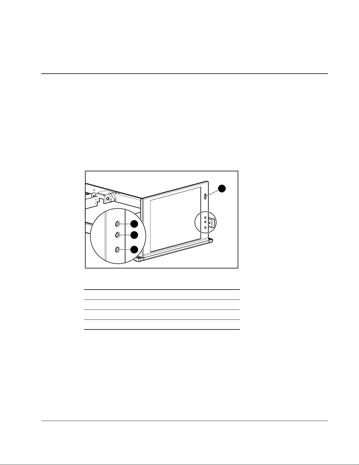
Front Panel Components
2
3
1
Introduction
1
4
Figure 1-1: Front panel components
Item Description
1 Power on/off switch
2 OSD scroll up button
3 OSD scroll down button
4 OSD activation button
HP TFT5110R Maintenance and Service Guide 1-1
Page 7
Introduction
Serial Number Location for the TFT5110R
You need to provide the serial number to HP when requesting information or ordering spare
parts for the TFT5110R. The serial number for the TFT5110R is located on the bottom of
the unit.
Figure 1-2: Serial number location
1-2 HP TFT5110R Maintenance and Service Guide
Page 8

Illustrated Spare Parts List
This chapter provides an illustrated parts breakdown and a spare parts list for the
HP TFT5110R. Refer to Figure 2-1 for the names of referenced spare parts.
2
HP TFT5110R Maintenance and Service Guide 2-1
Page 9
Illustrated Spare Parts List
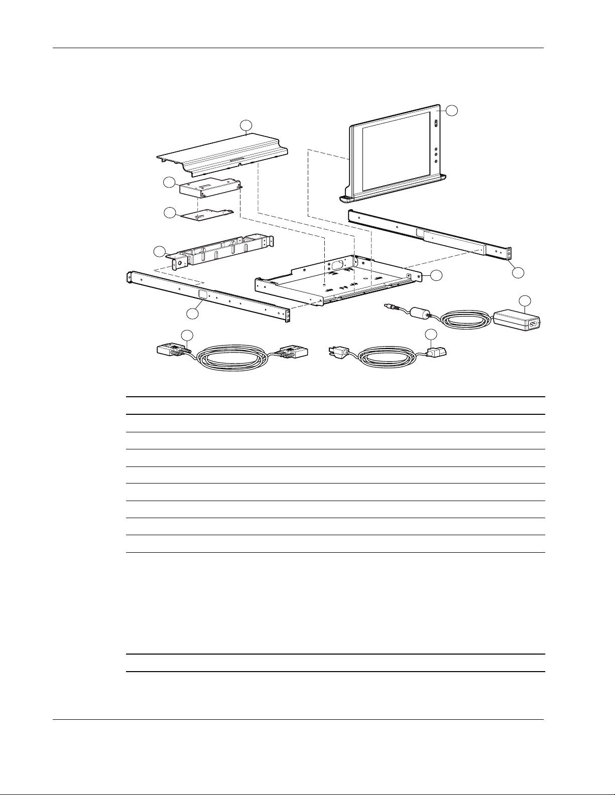
Components Exploded View
1
4
5
6
2
4
6
8
7
Figure 2-1: TFT5110R
Item Description Spare Part Number
1 SPS-PLASTIC KIT, MISC, 5110R 300963-001
2 SPS-MONITOR, TFT, 5110R, 1U 300962-001
3 SPS-ADPTRAC 40W 4PRONG/MINIJCK 218319-001
4 SPS-TRAY, METAL, 5110R 300964-001
5 SPS-BD, CNTRLR 229847-001
6 SPS-RACKMOUNT KIT, 5110R 300965-001
7 SPS-CA, AC LINE, C5-C14, ADAPTER 192514-001
8 SPS-CA, VGA, MALE-MALE, 9FT 238729-001
9 SPS-CORD, AC PWR, 10’, BLK* 255135-001
SPS-CORD, AC PWR, 10’, BLK-EURO* 255135-021
SPS-CORD, AC PWR, 10’, BLK-UK* 255135-031
SPS-CORD, AC PWR, 10’, BLK-IT* 255135-061
SPS-CORD, AC PWR, 10’, BLK-SI* 255135-111
SPS-CORD, AC PWR, 10’, BLK-JP* 255135-291
6
3
* Not shown
2-2 HP TFT5110R Maintenance and Service Guide
Page 10

3
Removal and Replacement Procedures
This chapter provides guidance for removing and replacing spare parts for the TFT5110R.
Before beginning these procedures, be sure to turn off the power to the display and
disconnect the power cable from the power source.
IMPORTANT: As you disassemble the TFT5110R, be sure to place the screws in a safe place and
separate them according to their groupings.
After completing all the necessary removal and replacement procedures, power on the
TFT5110R to verify that all of the components are operating properly.
HP TFT5110R Maintenance and Service Guide 3-1
Page 11

Removal and Replacement Procedures
Replaceable Spare Parts
The TFT5110R contains the following replaceable parts:
• SPS-PLASTIC KIT, MISC, 5110R 300963-001
— Rear cover
• SPS-MONITOR, TFT, 5110R, 1U 300962-001
• SPS-ADPTRAC 40W 4PRONG/MINIJCK 218319-001
• SPS-TRAY, METAL, 5110R 300964-001
• SPS-BD, CNTRLR 229847-001
• SPS-RACKMOUNT KIT, 5110R 330965-001
— Mounting rails w/slides
— Cable management arm assembly
• SPS-CA, AC LINE, C5-C14, ADAPTER 192514-001
• SPS-CA, VGA, MALE-MALE, 9FT 238729-001
• SPS-CORD, AC PWR, 10’, BLK 255135-XXX
Tools Required
• Phillips screwdriver
• T-15 Torx driver
• Cutting tool for tie wraps
3-2 HP TFT5110R Maintenance and Service Guide
Page 12

SPS-PLASTIC KIT, MISC, 5110R 300963-001
Removal and Replacement Procedures
Figure 3-1: Rear cover
HP TFT5110R Maintenance and Service Guide 3-3
Page 13

Removal and Replacement Procedures
Removing the Rear Cover
To remove the rear cover:
1. Rotate the monitor to an upright position.
2. Remove the rear screw (1), securing the rear cover to the metal tray.
3. Slide the rear cover back (2) and rotate it out of position (3).
3
2
Figure 3-2: Removing the rear cover
To replace the rear cover, reverse the above procedure.
1
3-4 HP TFT5110R Maintenance and Service Guide
Page 14

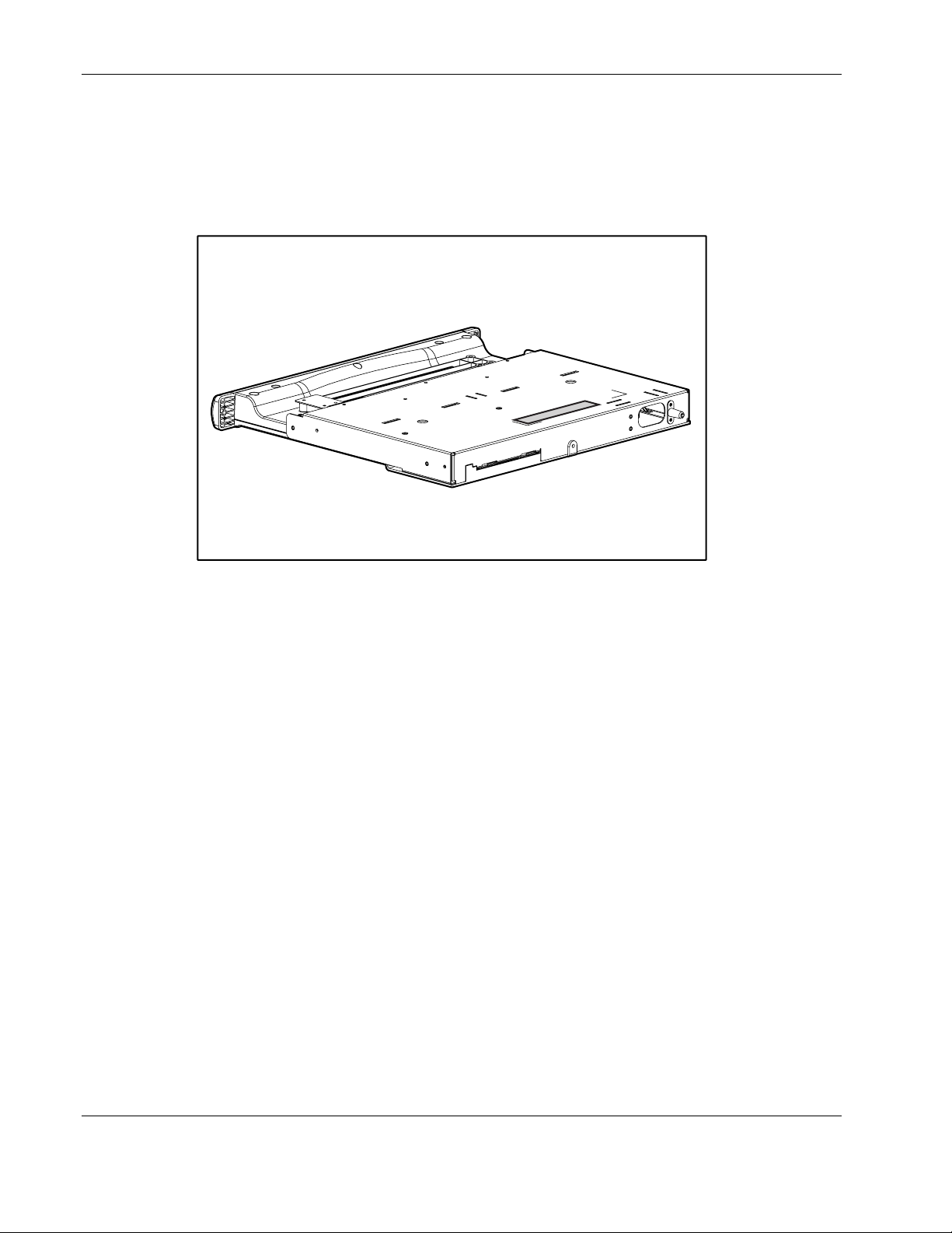
SPS-MONITOR, TFT, 5110R, 1U 300962-001
Removal and Replacement Procedures
Figure 3-3: Monitor
HP TFT5110R Maintenance and Service Guide 3-5
Page 15

Removal and Replacement Procedures
To remove the monitor:
1. Remove the rear cover.
2. Remove the screw securing the grounding clip and cable to the metal controller cover.
Figure 3-4: Removing the grounding clip
3. Unplug the three cables connecting the monitor to the controller board.
WARNING: Do not pull on the exposed wires. Pull only on the plastic shroud
connectors attached to the wires.
Figure 3-5: Disconnecting the cables
3-6 HP TFT5110R Maintenance and Service Guide
Page 16

Removal and Replacement Procedures
4. Cut the tie wrap securing the cables to the metal tray.
5. Remove the four screws (1) securing the monitor to the metal tray, and then remove the
monitor (2).
NOTE: The cables attached to the monitor are not shown in the figure below.
2
1
1
Figure 3-6: Removing the screws securing the monitor
To replace the monitor, reverse the above procedure.
HP TFT5110R Maintenance and Service Guide 3-7
Page 17

Removal and Replacement Procedures
SPS-ADPTRAC 40W 4PRONG/MINIJCK 218319-001
Figure 3-7: AC brick
3-8 HP TFT5110R Maintenance and Service Guide
Page 18

Removing the AC Brick
To remove the AC brick:
1. Disconnect all cables from their source.
2. Remove the rear cover.
3. Unplug the AC brick connector from the controller board and lift the brick off of
the Velcro pad.
Removal and Replacement Procedures
Figure 3-8: Removing AC brick
IMPORTANT: Be sure the AC brick is properly located on the Velcro pad so that the rear cover can
be installed.
To replace the AC brick, reverse the above procedure.
HP TFT5110R Maintenance and Service Guide 3-9
Page 19

Removal and Replacement Procedures
SPS-TRAY, METAL, 5110R 300964-001
Figure 3-9: Metal tray and metal controller cover
3-10 HP TFT5110R Maintenance and Service Guide
Page 20

SPS-BD, CNTRLR 229847-001
Removal and Replacement Procedures
Figure 3-10: Controller board
HP TFT5110R Maintenance and Service Guide 3-11
Page 21

Removal and Replacement Procedures
Removing the Metal Controller Cover and Controller board
To remove the metal controller cover:
1. Remove the rear cover.
2. Remove the AC brick.
3. Remove the screw securing the grounding clip to the metal controller cover.
4. Disconnect all cables from their source, except for the VGA cable.
5. Remove the two screws securing the metal controller cover to the metal tray.
Figure 3-11: Removing screws from metal controller cover
6. Slide the metal controller cover (1) and lift it straight out (2).
2
Figure 3-12: Removing metal controller cover
1
3-12 HP TFT5110R Maintenance and Service Guide
Page 22

Removal and Replacement Procedures
7. Unscrew the VGA cable.
8. Remove the two screw locks from the VGA cable connector.
9. Remove the three screws securing the controller board to the metal controller cover.
Figure 3-13: Removing screws from metal controller cover
10. Remove the controller board from the metal controller cover.
To replace the metal controller cover and controller board, reverse the above procedure.
HP TFT5110R Maintenance and Service Guide 3-13
Page 23

Removal and Replacement Procedures
SPS-RACKMOUNT KIT, 5110R 300965-001
Figure 3-14: Mounting rails w/slides and cable management
arm assembly
Item Description
1 Mounting rails w/slides
2 Cable management arm assembly
3-14 HP TFT5110R Maintenance and Service Guide
Page 24

Removing the Cable Management Arm Assembly
To remove the cable management arm assembly:
1. Disconnect all cables from their source.
2. Unthread the cables from the cable management arm.
3. Remove the two screws securing the cable management arm to the rear of the metal tray.
Removal and Replacement Procedures
Figure 3-15: Removing the cable management arm
4. Remove the screw (1) securing the cable management arm brace to the rail
(on each side), and remove the brace assembly (2).
2
1
Figure 3-16: Removing the cable management arm brace
HP TFT5110R Maintenance and Service Guide 3-15
Page 25

Removal and Replacement Procedures
To replace the cable management arm assembly, reverse the above procedure.
Removing the Mounting Rails w/Slides
IMPORTANT: You must remove the cable management arm assembly and the TFT5110R before
removing the mounting rails w/slides.
To remove the mounting rails w/slides:
1. Remove the screw (1) securing the mounting rails w/slides to the rear of the rack.
2. Remove the two screws (2) securing the mounting rails w/slides to the front of the rack.
3. Remove the mounting rails w/slides from the rack.
2
1
Figure 3-17: Removing the mounting rails w/slides
To replace the mounting rails w/slides, reverse the above procedure.
3-16 HP TFT5110R Maintenance and Service Guide
Page 26

SPS-CORD, AC PWR, 10’, BLK 255135-XXX
Table 3-1: Cords
Cord Spare Kit Number Cord Spare Kit Description
255135-001 SPS-CORD, AC PWR, 10’, BLK
255135-021 SPS-CORD, AC PWR, 10’, BLK-EURO
255135-031 SPS-CORD, AC PWR, 10’, BLK
255135-061 SPS-CORD, AC PWR, 10’, BLK
255135-111 SPS-CORD, AC PWR, 10’, BLK
255135-291 SPS-CORD, AC PWR, 10’, BLK
Removal and Replacement Procedures
HP TFT5110R Maintenance and Service Guide 3-17
Page 27

Specifications
Table 4-1: TFT5110R Specifications
Monitor
Type Flat panel, active matrix TFT LCD
Viewable Image Size 38.1 cm (15 inches)
Face Treatment Transparent protector with anti-glare coating
4
Maximum Weight
(unpacked)
Maximum Dimensions
Height 3.02 cm (1.19 inches)
Depth 40.05 cm (15.75 inches)
Width 42.06 cm (16.56 inches)
4.8 kg (10.6 lbs)
HP TFT5110R Maintenance and Service Guide 4-1
 Loading...