

Page 1

HP StorageWorks
X1000 and X3000 Network Storage System
user guide
Part number: 5697-0185
First edition: November 2009
Page 2

Legal and notice information
© Copyright 1999, 2009 Hewlett-Packard Development Company, L.P.
Confidential computer software. Valid license from HP required for possession, use or copying. Consistent with FAR 12.211
and 12.212, Commercial Computer Software, Computer Software Documentation, and Technical Data for Commercial Items
are licensed to the U.S. Government under vendor's standard commercial license.
The information contained herein is subject to change without notice. The only warranties for HP products and services are set
forth in the express warranty statements accompanying such products and services. Nothing herein should be construed as
constituting an additional warranty. HP shall not be liable for technical or editorial errors or omissions contained herein.
WARRANTY STATEMENT: To obtain a copy of the warranty for this product, see the warranty information website:
h
ttp://www.hp.com/go/storagewarranty
Intel, Itanium, Pentium, Intel Inside, and the Intel Inside logo are trademarks or registered trademarks of Intel Corporation or
its subsidiaries in the United States and other countries.
Microsoft, Windows, Windows XP, and Windows NT are U.S. registered trademarks of Microsoft Corporation.
Adobe and Acrobat are trademarks of Adobe Systems Incorporated.
Java is a US trademark of Sun Microsystems, Inc.
Oracle is a registered US trademark of Oracle Corporation, Redwood City, California.
UNIX is a registered trademark of The Open Group.
Printed in the US
Page 3

Contents
About this guide ................................................................................. 13
Intended audience .................................................................................................................... 13
Related documentation .............................................................................................................. 13
Document conventions and symbols ............................................................................................. 13
Rack stability ............................................................................................................................ 14
HP technical support ................................................................................................................. 15
Customer self repair .................................................................................................................. 15
Subscription service .................................................................................................................. 15
HP websites ............................................................................................................................. 15
Documentation feedback ........................................................................................................... 16
1 Installing and configuring the server ................................................... 17
Setup overview ......................................................................................................................... 17
Determine an access method ............................................................................................... 17
Check kit contents ..................................................................................................................... 17
Locate and record the serial number ............................................................................................ 18
Install the storage system hardware .............................................................................................18
Access the storage system .......................................................................................................... 18
Power on the server and log on ..................................................................................................19
Configure the storage system using the HP StorageWorks Rapid Startup Wizard ............................... 20
Complete system configuration ...................................................................................................21
Additional access methods ......................................................................................................... 22
Using the remote browser method ......................................................................................... 22
Using the Remote Desktop method ........................................................................................ 23
Using the Telnet Server method ............................................................................................ 23
Enabling Telnet Server .................................................................................................. 23
Default storage settings .............................................................................................................. 23
Physical configuration ......................................................................................................... 23
Default boot sequence ........................................................................................................ 25
2 Storage system component identification ............................................. 27
HP X1400 Network Storage System and X3400 Network Storage Gateway hardware
components ............................................................................................................................. 27
HP X1600 Network Storage System hardware components ............................................................ 29
HP X1800 Network Storage System and X3800 Network Storage Gateway hardware
components ............................................................................................................................. 32
SAS and SATA hard drive LEDs ................................................................................................... 36
Systems Insight Display LEDs ...................................................................................................... 37
Systems Insight Display LED combinations .................................................................................... 39
3 Administration tools .......................................................................... 41
HP StorageWorks Automated Storage Manager ........................................................................... 41
Microsoft Windows Storage Server 2008 administration tools ........................................................ 41
Remote Desktop for Administration ....................................................................................... 41
X1000 and X3000 Network Storage System 3
Page 4

Share and Storage Management .......................................................................................... 42
Microsoft Services for Network File System ............................................................................. 42
Active Directory Lightweight Directory Services (ADLDS) ........................................................... 43
Configuring ADLDS ...................................................................................................... 43
Single Instance Storage ....................................................................................................... 44
Print Management .............................................................................................................. 45
4 Storage management overview .......................................................... 47
Storage management elements ................................................................................................... 47
Storage management example ............................................................................................. 47
Physical storage elements .................................................................................................... 48
Arrays ........................................................................................................................ 49
Fault tolerance ............................................................................................................. 50
Online spares ............................................................................................................. 50
Logical storage elements ..................................................................................................... 50
Logical drives (LUNs) .................................................................................................... 50
Partitions .................................................................................................................... 51
Volumes ..................................................................................................................... 51
File system elements ............................................................................................................52
File sharing elements .......................................................................................................... 52
Volume Shadow Copy Service overview ................................................................................ 52
Using storage elements ....................................................................................................... 53
Clustered server elements .................................................................................................... 53
Network adapter teaming .......................................................................................................... 53
Management tools .................................................................................................................... 53
HP Systems Insight Manager ................................................................................................ 53
Management Agents .......................................................................................................... 54
5 File server management .................................................................... 55
File services features in Windows Storage Server 2008 ................................................................. 55
Storage Manager for SANs ................................................................................................. 55
Single Instance Storage ....................................................................................................... 55
File Server Resource Manager .............................................................................................. 55
Windows SharePoint Services .............................................................................................. 55
File services management .......................................................................................................... 56
Configuring data storage .................................................................................................... 56
Storage management utilities ............................................................................................... 56
Array management utilities ............................................................................................ 57
Array Configuration Utility ............................................................................................ 57
Disk Management utility ............................................................................................... 58
Guidelines for managing disks and volumes .......................................................................... 58
Scheduling defragmentation ................................................................................................ 59
Disk quotas ....................................................................................................................... 59
Adding storage ..................................................................................................................60
Expanding storage ...................................................................................................... 60
Extending storage using Windows Storage Utilities .......................................................... 61
Expanding storage for EVA arrays using Command View EVA ........................................... 61
Expanding storage using the Array Configuration Utility ................................................... 61
Volume shadow copies .............................................................................................................. 62
Shadow copy planning ....................................................................................................... 62
Identifying the volume .................................................................................................. 63
Allocating disk space ................................................................................................... 63
Identifying the storage area .......................................................................................... 64
Determining creation frequency ..................................................................................... 64
4
Page 5

Shadow copies and drive defragmentation ............................................................................ 65
Mounted drives ..................................................................................................................65
Managing shadow copies ................................................................................................... 65
The shadow copy cache file .......................................................................................... 66
Enabling and creating shadow copies ............................................................................ 67
Viewing a list of shadow copies ..................................................................................... 68
Set schedules .............................................................................................................. 68
Viewing shadow copy properties ................................................................................... 68
Redirecting shadow copies to an alternate volume ........................................................... 69
Disabling shadow copies .............................................................................................. 69
Managing shadow copies from the storage system desktop ..................................................... 70
Shadow Copies for Shared Folders ....................................................................................... 70
SMB shadow copies .................................................................................................... 71
NFS shadow copies ..................................................................................................... 72
Recovery of files or folders ............................................................................................ 73
Recovering a deleted file or folder .................................................................................. 73
Recovering an overwritten or corrupted file ...................................................................... 74
Recovering a folder ...................................................................................................... 74
Backup and shadow copies .......................................................................................... 75
Shadow Copy Transport ...................................................................................................... 75
Folder and share management ................................................................................................... 75
Folder management ............................................................................................................ 76
Share management ............................................................................................................ 82
Share considerations .................................................................................................... 82
Defining Access Control Lists ......................................................................................... 83
Integrating local file system security into Windows domain environments ............................. 83
Comparing administrative (hidden) and standard shares ................................................... 83
Managing shares ........................................................................................................ 84
File Server Resource Manager ....................................................................................................84
Quota management ........................................................................................................... 84
File screening management ................................................................................................. 85
Storage reports .................................................................................................................. 85
Other Windows disk and data management tools ......................................................................... 85
Additional information and references for file services .................................................................... 85
Backup ............................................................................................................................. 85
HP StorageWorks Library and Tape Tools .............................................................................. 85
Antivirus ............................................................................................................................ 86
6 Cluster administration ....................................................................... 87
Cluster overview ....................................................................................................................... 87
Cluster terms and components ....................................................................................................88
Nodes .............................................................................................................................. 88
Resources .......................................................................................................................... 88
Cluster groups ................................................................................................................... 89
Virtual servers .................................................................................................................... 89
Failover and failback .......................................................................................................... 89
Quorum disk .....................................................................................................................89
Cluster concepts ....................................................................................................................... 90
Sequence of events for cluster resources ................................................................................ 90
Hierarchy of cluster resource components .............................................................................. 91
Cluster planning ....................................................................................................................... 91
Storage planning ............................................................................................................... 92
Network planning .............................................................................................................. 92
Protocol planning ...............................................................................................................93
X1000 and X3000 Network Storage System 5
Page 6

Preparing for cluster installation .................................................................................................. 94
Before beginning installation ............................................................................................... 94
Using multipath data paths for high availability ...................................................................... 94
Checklists for cluster server installation .................................................................................. 94
Network requirements .................................................................................................. 94
Shared disk requirements .............................................................................................. 95
Cluster installation ..................................................................................................................... 95
Setting up networks ............................................................................................................ 96
Configuring the private network adapter ......................................................................... 96
Configuring the public network adapter .......................................................................... 96
Renaming the local area connection icons ...................................................................... 96
Verifying connectivity and name resolution ...................................................................... 96
Verifying domain membership ....................................................................................... 96
Setting up a cluster account .......................................................................................... 96
About the Quorum disk ................................................................................................ 96
Configuring shared disks .............................................................................................. 97
Verifying disk access and functionality ............................................................................ 97
Configuring cluster service software ............................................................................................. 97
Using Cluster Administrator ................................................................................................. 97
Creating a cluster ............................................................................................................... 97
Adding nodes to a cluster .................................................................................................... 98
Geographically dispersed clusters ........................................................................................ 98
Cluster groups and resources, including file shares ........................................................................ 98
Cluster group overview ....................................................................................................... 98
Node-based cluster groups ........................................................................................... 99
Load balancing ........................................................................................................... 99
File share resource planning issues ....................................................................................... 99
Resource planning ....................................................................................................... 99
Permissions and access rights on share resources ........................................................... 100
NFS cluster-specific issues ........................................................................................... 100
Non cluster aware file sharing protocols .............................................................................. 101
Adding new storage to a cluster ......................................................................................... 101
Creating physical disk resources .................................................................................. 101
Creating file share resources ....................................................................................... 101
Creating NFS share resources ..................................................................................... 102
Shadow copies in a cluster ................................................................................................ 102
Extend a LUN in a cluster .................................................................................................. 102
MSNFS administration on a server cluster ............................................................................ 102
Best practices for running Server for NFS in a server cluster ............................................. 103
Print services in a cluster .......................................................................................................... 103
Creating a cluster printer spooler ........................................................................................ 103
Advanced cluster administration procedures ............................................................................... 104
Failing over and failing back ............................................................................................. 104
Restarting one cluster node ................................................................................................ 105
Shutting down one cluster node .......................................................................................... 105
Powering down the cluster ................................................................................................. 105
Powering up the cluster ..................................................................................................... 106
7 Troubleshooting, servicing, and maintenance ..................................... 107
Troubleshooting the storage system ............................................................................................ 107
WEBES (Web Based Enterprise Services) ................................................................................... 107
Maintenance and service ......................................................................................................... 108
Maintenance updates ....................................................................................................... 108
System updates .......................................................................................................... 108
6
Page 7

Firmware updates ............................................................................................................. 108
Certificate of Authenticity ......................................................................................................... 108
8 System recovery ............................................................................. 109
The System Recovery DVD ........................................................................................................ 109
To restore a factory image ....................................................................................................... 109
Managing disks after a restoration ............................................................................................ 109
A Regulatory compliance notices ........................................................ 111
Regulatory compliance identification numbers ............................................................................ 111
Federal Communications Commission notice .............................................................................. 111
FCC rating label .............................................................................................................. 111
Class A equipment ..................................................................................................... 111
Class B equipment ..................................................................................................... 112
Declaration of Conformity for products marked with the FCC logo, United States only ............... 112
Modification .................................................................................................................... 112
Cables ............................................................................................................................ 112
Canadian notice (Avis Canadien) ............................................................................................. 112
Class A equipment ........................................................................................................... 112
Class B equipment ............................................................................................................ 113
European Union notice ............................................................................................................ 113
Japanese notices .................................................................................................................... 113
Japanese VCCI-A notice .................................................................................................... 113
Japanese VCCI-B notice .................................................................................................... 113
Japanese power cord statement .......................................................................................... 113
Korean notices ....................................................................................................................... 114
Class A equipment ........................................................................................................... 114
Class B equipment ............................................................................................................ 114
Taiwanese notices ................................................................................................................... 114
BSMI Class A notice ......................................................................................................... 114
Taiwan battery recycle statement ........................................................................................ 114
Laser compliance notices ......................................................................................................... 115
English laser notice ........................................................................................................... 115
Dutch laser notice ............................................................................................................. 115
French laser notice ........................................................................................................... 116
German laser notice ......................................................................................................... 116
Italian laser notice ............................................................................................................ 116
Japanese laser notice ........................................................................................................ 117
Spanish laser notice ......................................................................................................... 117
Recycling notices .................................................................................................................... 117
English notice .................................................................................................................. 117
Bulgarian notice ............................................................................................................... 118
Czech notice ................................................................................................................... 118
Danish notice .................................................................................................................. 118
Dutch notice .................................................................................................................... 118
Estonian notice ................................................................................................................ 119
Finnish notice ................................................................................................................... 119
French notice ................................................................................................................... 119
German notice ................................................................................................................. 119
Greek notice .................................................................................................................... 120
Hungarian notice ............................................................................................................. 120
Italian notice .................................................................................................................... 120
Latvian notice .................................................................................................................. 120
Lithuanian notice .............................................................................................................. 121
X1000 and X3000 Network Storage System 7
Page 8

Polish notice .................................................................................................................... 121
Portuguese notice ............................................................................................................. 121
Romanian notice .............................................................................................................. 121
Slovak notice ................................................................................................................... 122
Spanish notice ................................................................................................................. 122
Swedish notice ................................................................................................................. 122
Turkish notice ................................................................................................................... 122
Battery replacement notices ...................................................................................................... 123
Dutch battery notice .......................................................................................................... 123
French battery notice ........................................................................................................ 124
German battery notice ...................................................................................................... 124
Italian battery notice ......................................................................................................... 125
Japanese battery notice .................................................................................................... 125
Spanish battery notice ...................................................................................................... 126
Index ............................................................................................... 127
8
Page 9

Figures
HP StorageWorks Rapid Startup Wizard Welcome screen ............................................ 211
HP X1400 and X3400 front panel components .......................................................... 272
HP X1400 and X3400 front panel LEDs ..................................................................... 283
HP X1400 and X3400 rear panel components ........................................................... 284
HP X1400 and X3400 rear panel LEDs ..................................................................... 295
HP X1600 front panel components and LEDs .............................................................. 306
HP X1600 rear panel components ............................................................................ 317
HP X1600 (AW528A) rear panel components ............................................................ 328
HP X1800 and X3800 front panel components .......................................................... 339
HP X1800 and X3800 front panel LEDs and buttons ................................................... 3410
HP X1800 and X3800 rear panel components ........................................................... 3411
HP X1800 and X3800 rear panel LEDs and buttons .................................................... 3512
SAS/SATA hard drive LEDs ....................................................................................... 3613
Systems Insight Display LEDs ..................................................................................... 3814
Storage management process example ...................................................................... 4815
Configuring arrays from physical drives ...................................................................... 4916
RAID 0 (data striping) (S1-S4) of data blocks (B1-B12) ................................................ 4917
Two arrays (A1, A2) and five logical drives (L1 through L5) spread over five physical
18
drives .................................................................................................................... 51
System administrator view of Shadow Copies for Shared Folders ................................... 6619
Shadow copies stored on a source volume ................................................................. 6620
Shadow copies stored on a separate volume .............................................................. 6721
Accessing shadow copies from My Computer ............................................................. 7022
Client GUI ............................................................................................................. 7223
Recovering a deleted file or folder ............................................................................. 7424
Properties dialog box, Security tab ............................................................................ 7725
Advanced Security settings dialog box, Permissions tab ............................................... 7826
User or group Permission Entry dialog box ................................................................. 7927
Advanced Security Settings dialog box, Auditing tab ................................................... 8028
Select User or Group dialog box ............................................................................... 8029
Auditing Entry dialog box for folder name NTFS Test ................................................... 8130
Advanced Security Settings dialog box, Owner tab ..................................................... 8231
X1000 and X3000 Network Storage System 9
Page 10

Storage system cluster diagram ................................................................................. 8832
Cluster concepts diagram ......................................................................................... 9033
10
Page 11

Tables
Document conventions ............................................................................................. 131
HP Rapid Startup Wizard configuration options .......................................................... 202
Storage system RAID configurations ........................................................................... 243
HP X1400 and X3400 front panel LED descriptions ..................................................... 284
HP X1400 and X3400 rear panel LED descriptions ..................................................... 295
HP X1600 front panel component and LED descriptions ............................................... 306
HP X1800 and X3800 front panel LED and button descriptions .................................... 347
HP X1800 and X3800 rear panel LED and button descriptions ..................................... 358
SAS and SATA hard drive LED combinations ............................................................... 369
Systems Insight Display LED descriptions .................................................................... 3810
Systems Insight Display LEDs and internal health LED combinations ................................ 3911
Summary of RAID methods ....................................................................................... 5012
Tasks and utilities needed for storage system configuration ........................................... 5613
Sharing protocol cluster support ................................................................................ 9314
Power sequencing for cluster installation ..................................................................... 9515
X1000 and X3000 Network Storage System 11
Page 12

12
Page 13
About this guide
This guide provides information about installing, configuring, managing, and troubleshooting the
following HP StorageWorks Network Storage Systems:
• HP StorageWorks X1400 Network Storage System
• HP StorageWorks X1600 Network Storage System
• HP StorageWorks X1800 Network Storage System
• HP StorageWorks X3400 Network Storage Gateway
• HP StorageWorks X3800 Network Storage Gateway
Intended audience
This guide is intended for technical professionals with knowledge of:
• Microsoft® administrative procedures
• System and storage configurations
Related documentation
The following documents [and websites] provide related information:
• HP StorageWorks X1000 and X3000 Network Storage System installation instructions
• HP StorageWorks X1000 Automated Storage Manager user guide
• HP Integrated Lights-Out 2 User Guide
To obtain HP StorageWorks X1000 and X3000 Network Storage System documentation, go to http:/
/www.hp.com/go/nas, select your product family, product model, click Support for your product,
and then click Manuals.
Document conventions and symbols
Table 1 Document conventions
ElementConvention
Cross-reference links and e-mail addressesBlue text: Table 1
ttp://www.hp.com
Bold text
Website addressesBlue, underlined text: h
• Keys that are pressed
• Text typed into a GUI element, such as a box
• GUI elements that are clicked or selected, such as menu
and list items, buttons, tabs, and check boxes
Text emphasisItalic text
X1000 and X3000 Network Storage System 13
Page 14

Monospace text
ElementConvention
• File and directory names
• System output
• Code
• Commands, their arguments, and argument values
Monospace, italic text
Monospace, bold text
• Code variables
• Command variables
Emphasized monospace text
WARNING!
Indicates that failure to follow directions could result in bodily harm or death.
CAUTION:
Indicates that failure to follow directions could result in damage to equipment or data.
IMPORTANT:
Provides clarifying information or specific instructions.
NOTE:
Provides additional information.
TIP:
Provides helpful hints and shortcuts.
Rack stability
Rack stability protects personnel and equipment.
About this guide14
Page 15

WARNING!
To reduce the risk of personal injury or damage to equipment:
• Extend leveling jacks to the floor.
• Ensure that the full weight of the rack rests on the leveling jacks.
• Install stabilizing feet on the rack.
• In multiple-rack installations, fasten racks together securely.
• Extend only one rack component at a time. Racks can become unstable if more than one component
is extended.
HP technical support
For worldwide technical support information, see the HP support website:
http://www.hp.com/support
Before contacting HP, collect the following information:
• Product model names and numbers
• Technical support registration number (if applicable)
• Product serial numbers
• Error messages
• Operating system type and revision level
• Detailed questions
Customer self repair
HP customer self repair (CSR) programs allow you to repair your StorageWorks product. If a CSR
part needs replacing, HP ships the part directly to you so that you can install it at your convenience.
Some parts do not qualify for CSR. Your HP-authorized service provider will determine whether a
repair can be accomplished by CSR.
For more information about CSR, contact your local service provider, or see the CSR website:
http://www.hp.com/go/selfrepair
Subscription service
HP recommends that you register your product at the Subscriber's Choice for Business website:
http://www.hp.com/go/e-updates
After registering, you will receive e-mail notification of product enhancements, new driver versions,
firmware updates, and other product resources.
HP websites
For additional information, see the following HP websites:
•http://www.hp.com
X1000 and X3000 Network Storage System 15
Page 16

•http://www.hp.com/go/storage
•http://www.hp.com/service_locator
•http://www.hp.com/support/manuals
•http://www.hp.com/support/downloads
Documentation feedback
HP welcomes your feedback.
To make comments and suggestions about product documentation, please send a message to
storagedocsFeedback@hp.com. All submissions become the property of HP.
About this guide16
Page 17

1 Installing and configuring the server
Setup overview
The HP StorageWorks X1000 Network Storage System comes preinstalled with the Microsoft
Windows® Storage Server™ 2008 Standard x64 Edition operating system with Microsoft iSCSI
Software Target and HP X1000 Automated Storage Manager (HP ASM) included.
The HP StorageWorks X3000 Network Storage System comes preinstalled with the Microsoft
Windows® Storage Server™ 2008 Enterprise x64 Edition operating system with Microsoft iSCSI
Software Target and a Microsoft Cluster Service (MSCS) license included.
IMPORTANT:
• Windows Storage Server 2008 x64 operating systems are designed to support 32–bit applications
without modification; however, any 32–bit applications that are run on these operating systems
should be thoroughly tested before releasing the storage system to a production environment.
• Windows Storage Server x64 editions support only x64-based versions of Microsoft Management
Console (MMC) snap-ins, not 32-bit versions.
Determine an access method
Before you install the storage system, you need to decide on an access method.
The type of access you select is determined by whether or not the network has a Dynamic Host
Configuration Protocol (DHCP) server. If the network has a DHCP server, you can install the storage
system through the direct attachment or remote management methods. If your network does not have
a DHCP server, you must access the storage system through the direct attachment method.
The direct attachment method requires a display, keyboard, and mouse. These components are not
provided with the storage system.
IMPORTANT:
Only the direct attach and remote management access methods can be used to install the storage
system. After the storage system installation process is complete and the system's IP address has been
assigned, you can then additionally use the remote browser and remote desktop methods to access
the storage system.
Check kit contents
Remove the contents, making sure you have all the components listed below. If components are missing,
contact HP technical support.
• HP StorageWorks X1000 or X3000 Network Storage System (with operating system preloaded)
X1000 and X3000 Network Storage System 17
Page 18

• Power cord(s)
• Product Documentation and Safety and Disposal Documentation CD
• HP StorageWorks Storage System Recovery DVD
• End User License Agreement
• Certificate of Authenticity Card
• Slide rail assembly
• HP ProLiant Essentials Integrated Lights-Out 2 Advanced Pack
Locate and record the serial number
Before completing the installation portion of this guide, locate and write down the storage system's
serial number.
The storage system's serial number is located in three places:
• Top of the storage system
• Back of the storage system
• Inside the storage system shipping box
Install the storage system hardware
1. Install the rail kit by following the HP Rack Rail Kit installation instructions.
2. If connecting to the storage system using the direct attach method, connect the following cables
to the back panel of the storage system in the following sequence: keyboard, mouse, network
cable, monitor cable, and power cable.
NOTE:
• The keyboard, mouse, and monitor are not provided with the storage system.
• The X1600 does not include PS/2 ports for connecting a keyboard and mouse. You
must use USB-compatible keyboard and mouse devices with this storage system.
3. If connecting to the storage system using the remote management method, connect a network
cable to a data port, a network cable to the iLO 2 port, and power cable.
Access the storage system
Use either the direct connect or remote management method to connect to the storage system.
IMPORTANT:
Only the direct attach and remote management access methods can be used to install the storage
system. After the storage system installation process is complete and the system's IP address has been
assigned, you can then additionally use the remote browser and remote desktop methods to access
the storage system.
• Direct attach — Connect a monitor, keyboard, and mouse directly to the storage system. This access
method is mandatory if your network does not have a Dynamic Host Configuration Protocol (DHCP)
server.
Installing and configuring the server18
Page 19

NOTE:
• The keyboard, mouse, and monitor are not provided with the storage system.
• The X1600 does not include PS/2 ports for connecting a keyboard and mouse. You must use
USB-compatible keyboard and mouse devices with this storage system.
• Remote management — Access the storage system using the Integrated Lights-Out 2 remote man-
agement method:
1. Ensure that a network cable is connected to the iLO 2 port located on the back of the storage
system.
2. Locate the iLO 2 Network Settings tag attached to the storage system and record the default
user name, password, and DNS name.
3. From a remote computer, open a standard Web browser and enter the iLO 2 management
hostname of the storage system.
NOTE:
By default, iLO 2 obtains the management IP address and subnet mask from your
network’s DHCP server. The hostname found on the iLO 2 tag is automatically registered
with your network’s DNS server.
4. Using the default user information provided on the iLO 2 Network Settings tag, log on to the
storage system.
For detailed instructions on using iLO 2, see the HP Integrated Lights–Out 2 user guide.
Power on the server and log on
Power on the server after installing the hardware and connecting the cables. Powering on the server
for the first time initiates the storage system installation process.
1. Power on the system by pushing the power button on the front panel. If using iLO 2, click
Momentary Press on the Power Management page to power on the server, then click Launch on
the Status Summary page to open the iLO 2 Integrated Remote Console and complete the
installation process.
The storage system starts and displays an HP Network Storage System installation screen. The
storage system installation process takes approximately 10–15 minutes.
NOTE:
Your storage system comes pre-installed with the Microsoft Windows Storage Server 2008
operating system. There is no operating system installation required.
When the storage system installation process nears completion, the Windows Storage Server
2008 desktop displays the following message: The user's password must be changed before
logging on the first time. Log on to the storage system by establishing an Administrator password:
2. Click OK.
3. Type an Administrator password in the New password box.
X1000 and X3000 Network Storage System 19
Page 20
4. Re-type the Administrator password in the Confirm password box.
5. Click the blue arrow next to the Confirm password box.
6. Click OK.
After the Administrator password has been set, the storage system completes the installation
process and restarts.
7. When prompted, press CTRL+ALT+DELETE to log on to the system. If using iLO 2, on the iLO
2 Integrated Remote Console tab, click the button labeled CAD and then click the Ctrl-Alt-Del
menu item.
IMPORTANT:
After establishing the new Administrator password, be sure to remember it and record it in a safe
place if needed. HP has no way of accessing the system if the new password is lost.
After logging in for the first time, the Welcome screen of the HP StorageWorks Rapid Startup Wizard
opens. Use the HP StorageWorks Rapid Startup Wizard to set up your system with basic configuration
information.
Configure the storage system using the HP StorageWorks Rapid Startup Wizard
The HP StorageWorks Rapid Startup Wizard is displayed after logging in for the first time. This wizard
guides you through configuring system settings. The HP StorageWorks Rapid Startup Wizard provides
the following options for configuring the storage system:
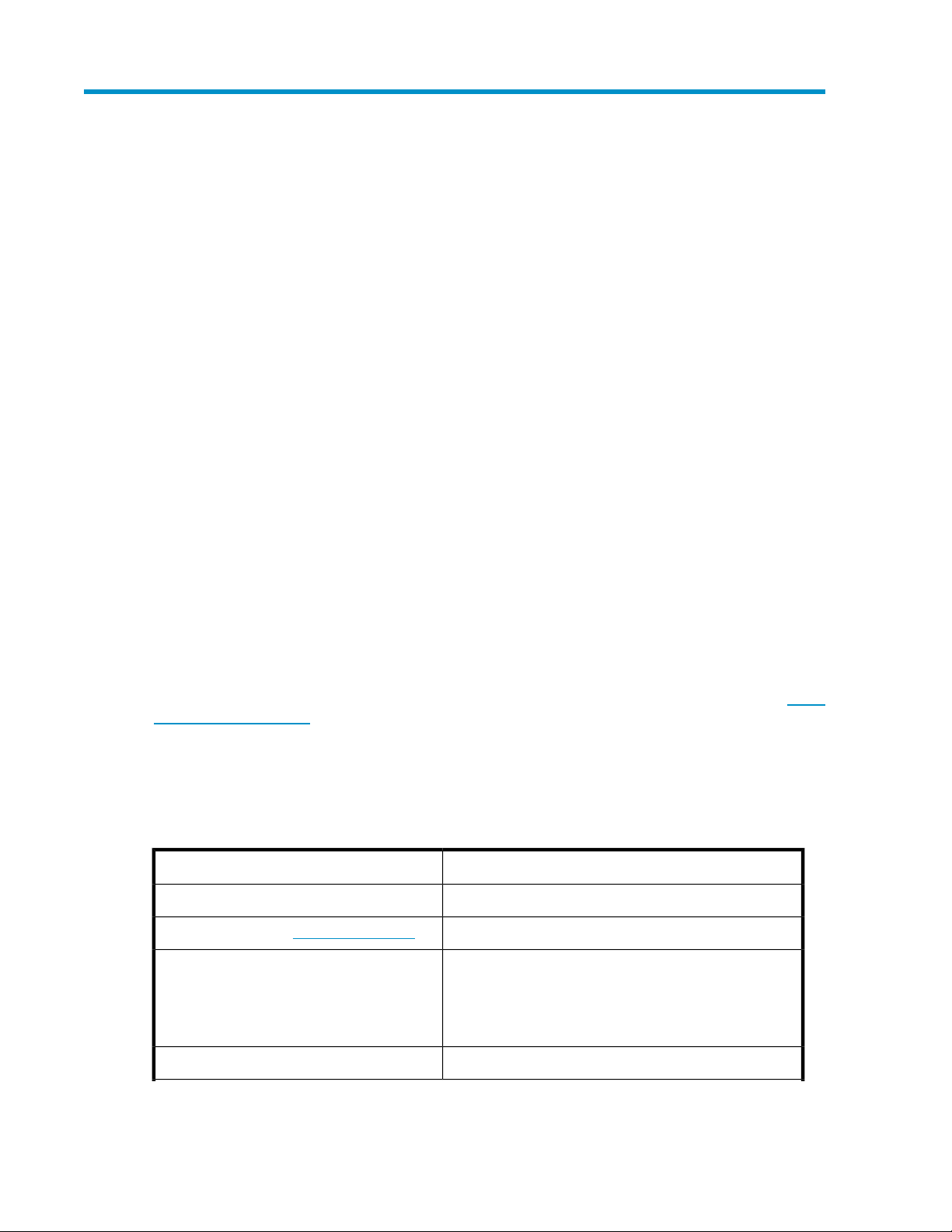
Table 2 HP Rapid Startup Wizard configuration options
Provide Computer Information
Customize This Server
Configure HP Recommended Settings
Configuration settingsRapid Startup Wizard Section
Set time zone, Configure networking, Provide computer name and domain
Enable automatic updating and feedback, Download and install updatesUpdate This Server
Add roles, Add features, Enable Remote Desktop, Configure Windows
Firewall
Alert E-mail Notification, SNMP Settings, HP Lights-Out Configuration
Utility
Installing and configuring the server20
Page 21
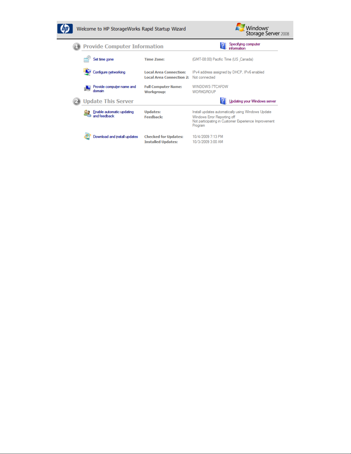
Figure 1 HP StorageWorks Rapid Startup Wizard Welcome screen
.
For detailed information about each of these configuration options, click the corresponding online
help link to the right of each section.
Complete system configuration
After the storage system is physically set up and the basic configuration is established, you must
complete additional setup tasks. Depending on the deployment scenario of the storage system, these
steps can vary. These additional steps can include:
• Running Microsoft Windows Update—HP highly recommends that you run Microsoft Windows
updates to identify, review, and install the latest, applicable, critical security updates on the storage
system.
• Creating and managing users and groups—User and group information and permissions determine
whether a user can access files. If the storage system is deployed into a workgroup environment,
this user and group information is stored locally on the device. By contrast, if the storage system
is deployed into a domain environment, user and group information is stored on the domain.
• Joining workgroup and domains—These are the two system environments for users and groups.
Because users and groups in a domain environment are managed through standard Windows or
Active Directory domain administration methods, this document discusses only local users and
groups, which are stored and managed on the storage system. For information on managing users
and groups on a domain, see the domain documentation available on the Microsoft web site.
If the storage system is deployed in a domain environment, the domain controller will store new
accounts on the domain; however, remote systems will store new accounts locally unless they are
granted permissions to create accounts on the domain.
• Using Ethernet NIC teaming (optional)—Select models are equipped with an HP or Broadcom
NIC Teaming utility. The utility allows administrators to configure and monitor Ethernet network
interface controller (NIC) teams in a Windows-based operating system. These teams provide options
for increasing fault tolerance and throughput.
• Activating iLO 2 Advanced features using a license key—The Remote Console feature of iLO 2
requires a license key. The key is included with the storage system inside the Country Kit. See the
iLO 2 Advanced License Pack for activation instructions.
• Adjusting logging for system, application, and security events.
X1000 and X3000 Network Storage System 21
Page 22

• Installing third-party software applications—For example, these might include an antivirus applic-
ation that you install.
• Registering the server — To register the server, refer to the HP Registration website (http://re-
gister.hp.com).
Additional access methods
After the storage system installation process is complete and the system's IP address has been assigned,
you can then additionally use the remote browser, Remote Desktop, and Telnet Server methods to
access the storage system.
Using the remote browser method
The storage system ships with DHCP enabled on the network port. If the server is placed on a
DHCP-enabled network and the IP address or server name is known, the server can be accessed
through a client running Internet Explorer 5.5 (or later) on that network, using the TCP/IP 3202 port.
IMPORTANT:
Before you begin this procedure, ensure that you have the following:
• Windows-based PC loaded with Internet Explorer 5.5 (or later) on the same local network as the
storage system
• DHCP-enabled network
• Server name or IP address of the storage system
To connect the server to a network using the remote browser method, ensure that the client is configured
to download signed ActiveX controls.
To connect the storage system to a network using the remote browser method
1. On the remote client machine open Internet Explorer and enter https:// and the server name
of the storage system followed by a hyphen (-), and then:3202. For example, https://
labserver-:3202. Press Enter.
NOTE:
If you are able to determine the IP address from your DHCP server, you can substitute the
IP address for the server name. For example: 192.100.0.1:3202.
2. Click OK on the Security Alert prompt.
3. Log on to the storage system with the administrator user name and password.
IMPORTANT:
If you are using the remote browser method to access the storage system, always close the remote
session before closing your Internet browser. Closing the Internet browser does not close the remote
session. Failure to close your remote session impacts the limited number of remote sessions allowed
on the storage system at any given time.
Installing and configuring the server22
Page 23

Using the Remote Desktop method
Remote Desktop provides the ability for you to log onto and remotely administer your server, giving
you a method of managing it from any client. Installed for remote administration, Remote Desktop
allows only two concurrent sessions. Leaving a session running takes up one license and can affect
other users. If two sessions are running, additional users will be denied access.
To connect the storage system to a network using the Remote Desktop method
1. On the PC client, select Start > Run. At Open, type mstsc, then click OK.
2. Enter the IP address of the storage system in the Computer box and click Connect.
3. Log on to the storage system with the administrator user name and password.
Using the Telnet Server method
Telnet Server is a utility that lets users connect to machines, log on, and obtain a command prompt
remotely. Telnet Server is preinstalled on the storage system but must be activated before use.
CAUTION:
For security reasons, the Telnet Server is disabled by default. The service needs to be modified to
enable access to the storage system with Telnet.
Enabling Telnet Server
The Telnet Server service needs to be enabled prior to its access.
1. In Server Manager, expand the Configuration node in the left panel.
2. Click System and Network Settings.
3. Under System Settings Configuration, click Telnet.
4. Check the Enable Telnet access to this server check box and then click OK.
Default storage settings
HP StorageWorks X1000 and X3000 Network Storage Systems are preconfigured with default storage
settings. This section provides additional details about the preconfigured storage.
Physical configuration
The logical disks reside on physical drives as shown in the table below.
As of the SWX image version 1.2, the DON'T ERASE volume that was created on earlier versions of
HP StorageWorks Network Storage System models is no longer used.
IMPORTANT:
The first two logical drives are configured for the storage system operating system.
X1000 and X3000 Network Storage System 23
Page 24

The Operating System volume default factory settings can be customized after the operating system
is up and running. The following settings can be changed:
• RAID level can be changed to any RAID level except RAID 0
• OS logical drive size can be changed to 40 GB or higher
If the Operating System volume is customized and the System Recovery DVD is run at a later time,
the System Recovery process will maintain the custom settings as long as the above criteria are met
(RAID level other than RAID 0 and OS logical drive size of 40 GB or higher) and the OS volume is
labeled System. If the storage system arrays are deleted and the System Recovery DVD is run, the
System Recovery process will configure the storage system using the factory default settings listed in
the table below.
HP StorageWorks X1000 and X3000 Network Storage Systems do not include preconfigured data
volumes. The administrator must configure data storage for the storage system. See
“Configuring data storage” on page 56 for more information.
Table 3 Storage system RAID configurations
Logical Disk 1Server model
HP StorageWorks X1400 Network Storage System
(all models)
• HP StorageWorks X1600 Network Storage System
(base model)
• HP StorageWorks X1600 5.4TB SAS Network
Storage System
• HP StorageWorks X1600 12TB SATA Network
Storage System
HP StorageWorks X1600 6TB SATA Network Storage
System
• HP StorageWorks X1800 Network Storage System
(base model)
• HP StorageWorks X1800 3.6 TB SAS Network
Storage System
• HP StorageWorks X1800 6TB SATA Network
Storage System
HP StorageWorks X1800 2.4TB SAS Network Storage
System
• Operating System Volume
• RAID 5
• Physical Drives 0–3
• Operating System Volume
• RAID 1+0
• Physical Drives 0–1
• Operating System Volume
• RAID 5
• Physical Drives 0–5
• Operating System Volume
• RAID 1+0
• Physical Drives 0–1
• Operating System Volume
• RAID 5
• Physical Drives 0–7
• HP StorageWorks X3400 Network Storage Gate-
way
• HP StorageWorks X3800 Network Storage Gate-
way
Installing and configuring the server24
• Operating System Volume
• RAID 1+0
• Physical Drives 0–1
Page 25

NOTE:
In the HP Array Configuration Utility (ACU), logical disks are labeled 1 and 2. In Microsoft Disk
Manager, logical disks are displayed as 0 and 1. For HP Smart Array configuration information, see
http://h18004.www1.hp.com/products/servers/proliantstorage/arraycontrollers/.
If the operating system has a failure that might result from corrupt system files, a corrupt registry, or
the system hangs during boot, see “System recovery” on page 109.
Default boot sequence
The BIOS supports the following default boot sequence:
1. DVD-ROM
2. HDD
3. Bootable USB flash drive
4. PXE (network boot)
Under normal circumstances, the storage systems boot up from the OS logical drive.
• If the system experiences a drive failure, the drive displays an amber disk failure LED.
• If a single drive failure occurs, it is transparent to the OS.
X1000 and X3000 Network Storage System 25
Page 26

Installing and configuring the server26
Page 27
2 Storage system component identification
This chapter provides illustrations of the storage system hardware components.
NOTE:
The keyboard, mouse, and monitor are used only for the direct attached method of accessing the
server. They are not provided with your storage system.
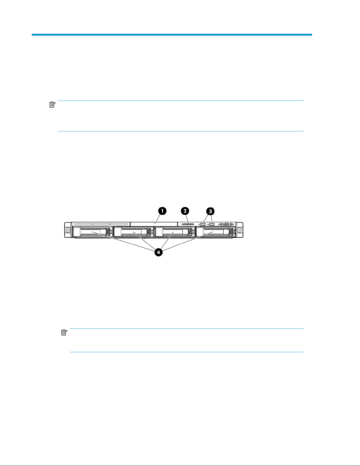
HP X1400 Network Storage System and X3400 Network Storage Gateway hardware components
The following figures show components and LEDs located on the front and rear panels of the X1400
Network Storage System and X3400 Network Storage Gateway.
Figure 2 HP X1400 and X3400 front panel components
.
1. DVD-RW drive
2. Serial label pull tab
3. Two (2) USB ports
4. Four (4) 3.5” hot-plug SAS/SATA hard drive bays
NOTE:
See “SAS and SATA hard drive LED combinations” on page 36 for HDD LED status descriptions.
X1000 and X3000 Network Storage System 27
Page 28
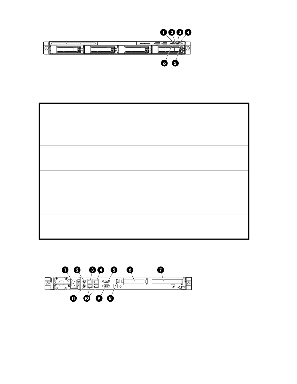
Figure 3 HP X1400 and X3400 front panel LEDs
.
Table 4 HP X1400 and X3400 front panel LED descriptions
StatusItem / Description
Green = System health is normal.
1. Internal health LED
Amber = System health is degraded.
Red = System health is critical.
Off = System health is normal (when in standby mode).
2. NIC 1 link/activity LED
3. NIC 2 link/activity LED
4. Drive activity LED
5. Power On/Standby button and system
power LED
6. UID button/LED
Green = Network link exists.
Flashing green = Network link and activity exist.
Off = No network link exists.
Green = Drive activity is normal.
Off = No drive activity exists.
Green = Normal (system on)
Amber = System is in standby, but power is still applied.
Off = Power cord is not attached or the power supply has failed.
Blue = Identification is activated.
Flashing blue = System is being managed remotely.
Off = Identification is deactivated.
Figure 4 HP X1400 and X3400 rear panel components
.
Storage system component identification28
Page 29
1. Power cord connector
2. Mouse connector
3. 10/100/1000 NIC 1 connector/shared iLO 2 management port
4. 10/100/1000 NIC 2 connector
5. Serial connector
6. Low profile PCIe slot cover (x16 slot open)
7. Full-sized PCIe slot (occupied by Smart Array P212 controller)
8. Dedicated iLO 2 management port (this port is optional and must be purchased separately)
9. Video connector
10. USB connectors (2)
11. Keyboard connector
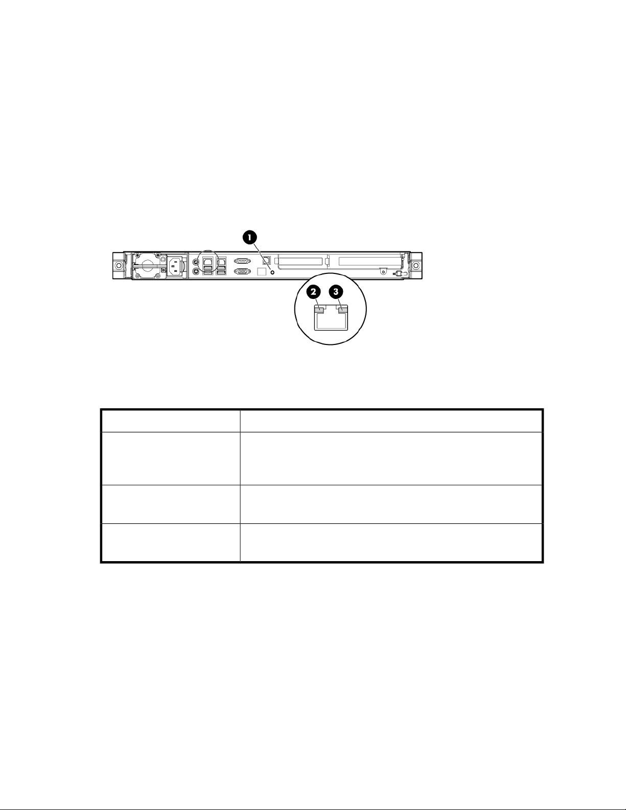
Figure 5 HP X1400 and X3400 rear panel LEDs
.
Table 5 HP X1400 and X3400 rear panel LED descriptions
StatusItem / Description
Blue = Activated
1. UID button/LED
2. NIC/iLO 2 link
3. NIC/iLO 2 activity
Flashing = System is being managed remotely.
Off = Deactivated
Green or flashing green = Activity exists.
Off = No activity exists.
Green = Link exists.
Off = No link exists.
HP X1600 Network Storage System hardware components
The following figures show components and LEDs located on the front and rear panels of the HP
X1600 Network Storage System.
X1000 and X3000 Network Storage System 29
Page 30
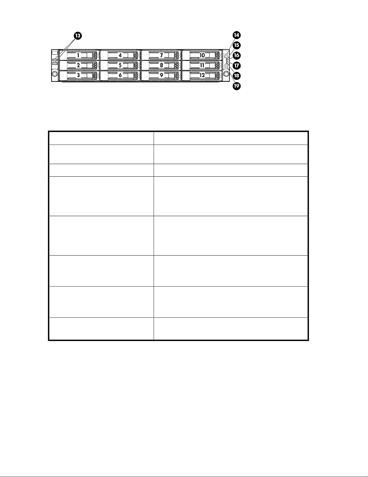
Figure 6 HP X1600 front panel components and LEDs
.
Table 6 HP X1600 front panel component and LED descriptions
StatusItem / Description
1 — 12. Twelve 3.5” (LFF) hot plug SATA
/ SAS hard drive bays
14. Unit identification (UID) LED button
15. System health LED
16. NIC1 LED
17. NIC2 LED
18. HDD LED
19. Power button
See “SAS and SATA hard drive LED combinations” on page 36
for HDD LED status descriptions.
N/A13. Front USB ports (2)
Green = Normal (system on)
Flashing amber = System health degraded
Flashing red = System health critical
Off = Normal (system off)
Green = Normal (system on)
Flashing amber = System health degraded
Flashing red = System health critical
Off = Normal (system off)
Green = Network link
Flashing = Network link and activity
Off = No network connection
Green = HDD install ready
Flashing green = Data access
Off = No access
Green = System on
Amber = System off
Storage system component identification30
Page 31

Figure 7 HP X1600 rear panel components
.
1. Redundant hot-plug power supplies
2. Power supply cable socket
3. Rear DVD-RW drive
4. x8 full-length /full-height PCI-Express slot
5. x8 full-length /full-height PCI-Express slot (occupied by Smart Array P212 controller)
6. UID LED button
7. iLO 2 management port
8. LAN port
9. LAN port
10. Two (2) rear USB 2.0 ports
11. VGA port
12. Serial port
X1000 and X3000 Network Storage System 31
Page 32

Figure 8 HP X1600 (AW528A) rear panel components
.
The HP X1600 Network Storage System AW528A model includes two 2.5” Small Form Factor (SFF)
SAS / SATA hot plug hard drives in the rear of the unit that are configured for the operating system.
This allows for the use of up to twelve hard drives on the front of the unit to be configured for storage.
In addition, the AW528A model includes two PCI-Express (PCIe) slots.
1. Redundant hot-plug power supplies
2. Power supply cable socket
3. Low profile PCIe slot (x16 slot open)
4. 2.5” SFF SAS / SATA hot plug hard drive
5. 2.5” SFF SAS / SATA hot plug hard drive
6. x8 full-length /full-height PCIe slot (occupied by Smart Array P212 controller)
7. UID LED button
8. iLO 2 management port
9. LAN port
10. LAN port
11. Two (2) rear USB 2.0 ports
12. VGA port
13. Serial port
HP X1800 Network Storage System and X3800 Network Storage Gateway hardware components
The following figures show components and LEDs located on the front and rear panels of the X1800
Network Storage System and X3800 Network Storage Gateway.
Storage system component identification32
Page 33

Figure 9 HP X1800 and X3800 front panel components
.
1. Quick release levers (2)
2. Systems Insight Display
NOTE:
See “Systems Insight Display LEDs” on page 37 and
“Systems Insight Display LED combinations” on page 39 for LED status information.
3. Eight (8) 2.5” SFF SAS / SATA hot plug hard drive bays
NOTE:
See “SAS and SATA hard drive LED combinations” on page 36 for HDD LED status descriptions.
4. DVD-RW drive
5. Video connector
6. USB connectors (2)
X1000 and X3000 Network Storage System 33
Page 34

Figure 10 HP X1800 and X3800 front panel LEDs and buttons
.
Table 7 HP X1800 and X3800 front panel LED and button descriptions
StatusItem / Description
Blue = Activated
1. UID LED and button
2. System health LED
Flashing blue = System being remotely managed
Off = Deactivated
Green = Normal
Amber = System degraded
Red = System critical
To identify components in degraded or critical state, see
3. Power On/Standby
button and system power
LED
Green = System on
Amber = System in standby, but power is still applied
Off = Power cord not attached or power supply failure
Figure 11 HP X1800 and X3800 rear panel components
.
1. PCIe slot 5
Storage system component identification34
Page 35

2. PCIe slot 6
3. PCIe slot 4
4. PCIe slot 2
5. PCIe slot 3
6. PCIe slot 1 (occupied by Smart Array controller with external SAS ports for expandability)
7. Power supply 2 (standard)
8. Power supply 1 (standard)
9. USB connectors (2)
10. Video connector
11. NIC 1 connector
12. NIC 2 connector
13. Mouse connector
14. Keyboard connector
15. Serial connector
16. iLO 2 connector
17. NIC 3 connector
18. NIC 4 connector
Figure 12 HP X1800 and X3800 rear panel LEDs and buttons
.
Table 8 HP X1800 and X3800 rear panel LED and button descriptions
StatusItem / Description
1. Power supply LED
2. UID LED/button
Green = Normal
Off = System is off or power supply has failed
Blue = Activated
Flashing blue = System being managed remotely
Off = Deactivated
X1000 and X3000 Network Storage System 35
Page 36

3. NIC/iLO 2 activity LED
StatusItem / Description
Green = Network activity
Flashing green = Network activity
Off = No network activity
4. NIC/iLO 2 link LED
Green = Network link
Off = No network link
SAS and SATA hard drive LEDs
The following figure shows SAS/SATA hard drive LEDs. These LEDs are located on all HP ProLiant
hot plug hard drives.
Figure 13 SAS/SATA hard drive LEDs
.
Table 9 SAS and SATA hard drive LED combinations
1. Fault/UID LED (am-
ber/blue)
Amber, flashing regularly (1
Hz)
(green)
On, off, or flashingAlternating amber and blue
On, off, or flashingSteadily blue
On
Status2. Online/activity LED
The drive has failed, or a predictive failure alert has
been received for this drive; it also has been selected
by a management application.
The drive is operating normally, and it has been selected by a management application.
A predictive failure alert has been received for this
drive. Replace the drive as soon as possible.
The drive is online, but it is not active currently.OnOff
Storage system component identification36
Page 37

1. Fault/UID LED (amber/blue)
Amber, flashing regularly (1
Hz)
(green)
Flashing regularly (1 Hz)
Flashing regularly (1 Hz)Off
Status2. Online/activity LED
Do not remove the drive. Removing a drive may
terminate the current operation and cause data loss.
The drive is part of an array that is undergoing capacity expansion or stripe migration, but a predictive
failure alert has been received for this drive. To
minimize the risk of data loss, do not replace the
drive until the expansion or migration is complete.
Do not remove the drive. Removing a drive may
terminate the current operation and cause data loss.
The drive is rebuilding, or it is part of an array that
is undergoing capacity expansion or stripe migration.
Amber, flashing regularly (1
Hz)
Amber, flashing regularly (1
Hz)
Flashing irregularly
OffSteadily amber
Off
OffOff
Systems Insight Display LEDs
The HP Systems Insight Display LEDs represent the system board layout. The display enables diagnosis
with the access panel installed.
The drive is active, but a predictive failure alert has
been received for this drive. Replace the drive as
soon as possible.
The drive is active, and it is operating normally.Flashing irregularlyOff
A critical fault condition has been identified for this
drive, and the controller has placed it offline. Replace the drive as soon as possible.
A predictive failure alert has been received for this
drive. Replace the drive as soon as possible.
The drive is offline, a spare, or not configured as
part of an array.
X1000 and X3000 Network Storage System 37
Page 38

Figure 14 Systems Insight Display LEDs
.
Table 10 Systems Insight Display LED descriptions
StatusItem / Description
Green = Network link
Flashing green = Network link and activity
1. NIC link/activity LED
Off = No link to network. If the power is off, view the rear panel RJ-45
LEDs for status (see “HP X1800 Network Storage System and X3800
Network Storage Gateway rear panel LEDs and buttons” on page 35).
2. Power cap
3. AMP status
All other LEDs
Storage system component identification38
To determine Power cap status, see “Systems Insight Display LED combin-
ations” on page 39.
Green = AMP mode enabled
Amber = Failover
Flashing amber = invalid configuration
Off = AMP modes disabled
Off = Normal
Amber =Failure
For detailed information on the activation of these LEDs, see “Systems
Insight Display LED combinations” on page 39.
Page 39

Systems Insight Display LED combinations
When the internal health LED on the front panel illuminates either amber or red, the server is
experiencing a health event. Combinations of illuminated system LEDs and the internal health LED
indicate system status.
Table 11 Systems Insight Display LEDs and internal health LED combinations
Systems Insight
Display LED and
color
Processor failure,
socket X (amber)
PPM failure, slot X
(amber)
DIMM failure, slot X
(amber)
DIMM failure, all
slots in one bank
(amber)
color
Red
Red
Red
StatusInternal health LED
One or more of the following conditions may exist:
• Processor in socket X has failed.
• Processor X is not installed in the socket.
• Processor X is unsupported.
• ROM detects a failed processor during POST.
Processor in socket X is in a pre-failure condition.Amber
One or more of the following conditions may exist:
• PPM in slot X has failed.
• PPM is not installed in slot X, but the corresponding pro-
cessor is installed.
DIMM in slot X has failed.Red
DIMM in slot X is in a pre-failure condition.Amber
One or more DIMMs has failed. Test each bank of DIMMs by
removing all other DIMMs. Isolate the failed DIMM by replacing
each DIMM in a bank with a known working DIMM.
DIMM failure, all
slots in all banks
(amber)
Online spare
memory (amber)
Online spare
memory (flashing
amber)
Online spare
memory (green)
Mirrored memory
(amber)
Mirrored memory
(flashing (amber)
Mirrored memory
(green)
Red
One or more DIMMs has failed. Test each bank of DIMMs by
removing all other DIMMs. Isolate the failed DIMM by replacing
each DIMM in a bank with a known working DIMM.
Bank X failed over to the online spare memory bank.Amber
Invalid online spare memory configuration.Red
Online spare memory enabled and not failed.Green
Bank(s) X failed over to the mirrored memory bank(s).Amber
Invalid mirrored memory configuration.Red
Mirrored memory enabled and not failed.Green
X1000 and X3000 Network Storage System 39
Page 40

Systems Insight
Display LED and
color
StatusInternal health LED
color
Overtemperature
(amber)
Riser interlock (amber)
Fan (amber)
The Health Driver has detected a cautionary temperature level.Amber
The server has detected a hardware critical temperature level.Red
PCI riser cage is not seated.Red
One fan has failed or is removed.Amber
Two or more fans have failed or are removed.Red
Storage system component identification40
Page 41

3 Administration tools
HP StorageWorks X1000 and X3000 Network Storage Systems include several administration tools
to simplify storage system management tasks. HP StorageWorks X1000 Network Storage Systems
include the HP X1000 Automated Storage Manager (ASM) in addition to HP storage utilities and
Microsoft® Windows® Storage Server 2008 administration tools.
HP StorageWorks Automated Storage Manager
After installing and setting up your storage system, you can begin managing your storage using the
HP Automated Storage Manager (HP ASM). HP ASM comes preinstalled on all HP X1000 Network
Storage Systems.
NOTE:
HP ASM is not supported and cannot be installed on HP X3000 Network Storage Systems.
ASM provides storage-allocation wizards that walk you through the process of allocating and
configuring storage on your HP Network Storage System to host application data and shared folders.
The storage-allocation wizards also allow you to schedule backups, snapshots, and replication of
hosted application data and shared folders. Other wizards are provided to help you set up Exchange
Server storage, SQL Server database storage, storage for user-defined applications, and storage for
shared folders.
For more information about using the HP Automated Storage Manager, see the HP ASM online help
or the HP StorageWorks X1000 Automated Storage Manager user guide. Go to http://www.hp.com/
go/nas, select your product family, select your product model, click Support for your product, and
then click Manuals.
Microsoft Windows Storage Server 2008 administration tools
Microsoft® Windows® Storage Server 2008 operating systems provide a user interface for initial
server configuration, unified storage system management, simplified setup and management of storage
and shared folders, and support for Microsoft iSCSI Software Target. It is specially tuned to provide
optimal performance for network-attached storage. Windows Storage Server 2008 provides significant
enhancements in share and storage management scenarios, as well as integration of storage system
management components and functionality.
Remote Desktop for Administration
You can remotely administer storage systems by using Remote Desktop for Administration (formerly
known as Terminal Services in Remote Administration mode). You can use it to administer a computer
from virtually any computer on your network. Based on Terminal Services technology, Remote Desktop
for Administration is specifically designed for server management.
X1000 and X3000 Network Storage System 41
Page 42

Remote Desktop for Administration does not require the purchase of special licenses for client computers
that access the server. It is not necessary to install Terminal Server Licensing when using Remote
Desktop for Administration.
You can use Remote Desktop for Administration to log on to the server remotely with any of the
following features:
• Remote Desktop Connection
• Remote Web Administration
• Windows Server Remote Administration Applet
For more information, see the Windows Storage Server 2008 Help.
Share and Storage Management
With the Share and Storage Management snap-in provided in this release, you can more easily set
up and manage shared folders and storage. Share and Storage Management provides the following:
• MMC-based management of shared folders and storage.
• Provision Storage Wizard for creating and configuring storage for file sharing and block sharing,
including creating LUNs on storage subsystems, as well as creating and formatting volumes on
LUNs or server disks.
NOTE:
You must have a VDS Hardware Provider that is appropriate for your storage system installed in
order to provision storage on an iSCSI target. If you have Microsoft iSCSI Software Target running
on a Windows Storage Server 2008 storage system, install the Microsoft iSCSI Software Target
VDS Hardware Provider on the client computer.
• Provision a Shared Folder Wizard for creating and configuring shared folders that can be accessed
by using either the server message block (SMB) or NFS protocol.
• Single Instance Storage (SIS) can be enabled or disabled for each volume that is displayed in
Share and Storage Management. SIS recovers disk space by reducing the amount of redundant
data stored on a volume. It identifies identical files, storing only a single copy of the file in the SIS
Common Store, and replacing the files with pointers to the file in the SIS Common Store.
The Share and Storage Management snap-in makes it possible to complete most of the administrative
tasks that are required to create and manage shared folders and volumes without having to use the
Shared Folder Management, Storage Manager for SANs, or Disk Management snap-ins. These tasks
include configuring quotas to restrict the quantity of data, configuring file screening to prevent certain
file types or only allowing certain file types defined by the administrator, and enabling indexing.
For more information, see the Windows Storage Server 2008 Help.
Microsoft Services for Network File System
Microsoft Services for Network File System (NFS) is a component of Windows Storage Server 2008
that provides a file-sharing solution for enterprises that have a mixed Windows and UNIX environment.
By using Microsoft Services for NFS, you can configure storage services to make it possible for users
to store and access files on the storage system, and to transfer files between the storage system and
UNIX computers by using the NFS protocol.
In Windows Storage Server 2008, you can complete the initial configuration of Microsoft Services
for NFS by using the Microsoft Services for NFS Configuration Guide, which includes an Identity
Administration tools42
Page 43

Mapping Setup Wizard. After completing the initial Microsoft Services for NFS configuration, you
can use the Microsoft Services for NFS console for ongoing maintenance and administration.
If you are using Windows Storage Server 2008 in an environment that does not include an Active
Directory directory service domain, you can install Active Directory Application Mode (ADAM) on
your storage system to provide user name mapping for NFS. Microsoft Services for NFS can use any
RFC 2307 compliant Lightweight Directory Access Protocol (LDAP) service to provide username
mapping services.
For more information, see the Windows Storage Server 2008 Help.
Active Directory Lightweight Directory Services (ADLDS)
Windows Storage Server 2008 no longer includes the User Name Mapping (UNM) service for UNIX
to Windows user mapping. The Services for Network File System feature now requires that users
utilize an existing UNM server or utilize Active Directory to map UNIX users to Windows users. HP
X1000 and X3000 systems utilize the Active Directory Lightweight Directory Services (ADLDS) role
to eliminate these requirements for standalone servers. Additionally, a utility script is provided for
configuration.
Configuring ADLDS
The following examples describe the format of a password and a group file. Password and group
files can be created or copied from the NFS client system.
Password file syntax
Each line of a standard UNIX password file follows this format:
user:password:UID:GID:comment:home directory:command shell
All fields are required, but the only fields that are used are the user, UID, and GID fields.
Group file syntax
Each line of a standard UNIX group file follows this format:
Group:password:GID:group list
All fields are required, but only the Group and GID fields are used. The GID field value must match
the GID field value in the password file for those users that belong to the group.
IMPORTANT:
• User names in the password file cannot match group names in the group file. Windows does not
allow user names and group names to be the same.
• All users included in the password file are imported. Consider removing some users from the file
before running the configuration script.
• All groups in the group file are imported. Consider removing some groups from the group file
before running the configuration script.
• Every imported user must have a password before that user can be used for user name mapping.
You can specify a common password for all imported users on the script command line.
• If specifying the password on the command line, you must use a password that meets the password
strength requirements of your system. By default Windows Storage Server 2008 requires strong
passwords.
X1000 and X3000 Network Storage System 43
Page 44

Script execution
You can configure ADLDS by executing the nfs-adam-config.js script that is located in the
c:\hpnas\components\ADLDS directory. Executing the script with no command line options will display
a help dialog. The following is a typical command line:
nfs-adam-config.js /passwd:<password file> /group:<group file> /ldf:out.ldf
/usercmd:generateusers.cmd /execute /log:<log file> /
userpassword:<password>
where:
• <password file> = path to UNIX password file
• <group file> = path to UNIX group file
• <log file> = path to log file containing the results of the script execution
• <password> = the Windows password assigned to all imported users
Verifying script execution
After the script is successfully executed, the users in the password file are listed as users on the storage
system and the groups are added. You can verify this with Server Manager:
1. Click Start, right click Computer, and then select Manage.
2. Expand the Configuration and Local Users and Groups nodes.
The imported users and groups are listed in the Users and Groups folders, respectively. If there are
errors, the log file (if specified) contains useful information to help debug problems.
NOTE:
When UNIX groups are imported, the associated UNIX users are not bound to the imported groups.
To include a user in an imported group, you must manually add the users to the group.
Shared access example
Because the imported users are now Windows users, access control for volumes (drives), folders, and
files can be controlled as if the users were local Windows users. Consider the scenario in which a
folder has subfolders that contain individual users’ private files. In addition, a public folder exists for
everyone to read files from. Some users utilize NFS to access their data and some users utilize SMB
(CIFS) to access their files. To control access, create a share for the top level folder and allow everyone
full control access to the share (use the Everyone group). For each user folder, configure the security
settings to allow only that user read-write access. Some users will be imported users and some will
be native Windows users. For the public folder, enable all users read-only access.
Single Instance Storage
The Single Instance Storage (SIS) feature reduces the amount of space that is used to store data on a
volume. SIS does this by replacing duplicate files with logical links that point to a single copy of the
file in the SIS Common Store, which is a hidden folder that is located in the root directory of the
volume.
SIS consists of two primary components that together maintain a database of file signatures. These
components include:
Administration tools44
Page 45

• Groveler service - The Groveler service scans the hard-disk volumes on a server for duplicate
copies of files. If the service locates duplicate copies of files, the information about the duplicates
is sent to the Single Instance Storage Filter. The Groveler service runs as a user-level service.
• Single Instance Storage Filter - The Single Instance Storage Filter is a file system filter service that
manages duplicate copies of files on hard-disk volumes. When notified by the Groveler service
of duplicate copies of files, this component copies one instance of a duplicate file into a central
folder. The duplicate is then replaced by a link (a reparse point) to the central copy. The link file
contains information about the original file, such as its current location, size, and attributes. The
Single Instance Storage Filter runs in kernel mode.
The Single Instance Storage Filter service cannot be stopped. If this service is disabled, the linked files
are not accessible. If the central folder is deleted, the linked files can become permanently inaccessible.
If you stop the Groveler service, the files cannot be automatically linked, but the existing linked files
can still be accessible.
You can enable SIS on a maximum of 20 volumes per computer. SIS cannot act upon any files that
are referenced through junction points, and it cannot be used with any file system except the NTFS
file system. SIS will not process files that are 32 kilobytes or less in size.
If you need to access data that is stored on a SIS volume, which might be required for backup and
recovery operations, you must either run or have installed Single Instance Storage Filter on your
computer.
Backup and recovery by using SIS has the following requirements:
• The backup software used must support SIS-enabled volumes.
• The SIS volume, SIS Common Store folder, and reparse points (links) to the files must be restored
to a Windows 2000 NTFS version 5.0 (or later) file system or partition that supports reparse points
or junction points.
• The Single Instance Storage Filter must be installed or enabled to access the data in the SIS volume.
• The backup program must be capable and configured to backup and restore the reparse points
or junction points (links) to the files, and the SIS volume and the SIS Common Store folder must
be selected.
For more information, see the Windows Storage Server 2008 Help.
Print Management
Print Management is an MMC snap-in that you can use to view and manage printers and print servers
in your organization. You can use Print Management from any computer running Windows Storage
Server 2008, and you can manage all network printers on print servers running Windows 2000
Server, Windows Server 2003, Windows Storage Server 2003, Windows Storage Server 2003 R2,
or Windows Storage Server 2008.
Print Management provides details such as the queue status, printer name, driver name, and server
name. You can also set custom views by using the Print Management filtering capability. For example,
you can create a view that displays only printers in a particular error state. You can also configure
Print Management to send e-mail notifications or run scripts when a printer or print server needs
attention. The filtering capability also allows you to bulk edit print jobs, such as canceling all print
jobs at once. You can also delete multiple printers at the same time.
Administrators can install printers remotely by using the automatic detection feature, which finds and
installs printers on the local subnet to the local print server. Administrators can log on remotely to a
server at a branch location, and then install printers remotely.
For more information, see the Windows Storage Server 2008 Help.
X1000 and X3000 Network Storage System 45
Page 46

Administration tools46
Page 47

4 Storage management overview
This chapter provides an overview of some of the components that make up the storage structure of
the storage system.
Storage management elements
Storage is divided into four major divisions:
• Physical storage elements
• Logical storage elements
• File system elements
• File sharing elements
Each of these elements is composed of the previous level's elements.
Storage management example
Figure 15 depicts many of the storage elements that one would find on a storage device. The following
sections provide an overview of the storage elements.
X1000 and X3000 Network Storage System 47
Page 48

Figure 15 Storage management process example
.
Physical storage elements
The lowest level of storage management occurs at the physical drive level. Minimally, choosing the
best disk carving strategy includes the following policies:
• Analyze current corporate and departmental structure.
• Analyze the current file server structure and environment.
• Plan properly to ensure the best configuration and use of storage.
• Determine the desired priority of fault tolerance, performance, and storage capacity.
• Use the determined priority of system characteristics to determine the optimal striping policy
and RAID level.
Storage management overview48
Page 49

Arrays
• Include the appropriate number of physical drives in the arrays to create logical storage elements
of desired sizes.
See Figure 16. With an array controller installed in the system, the capacity of several physical drives
(P1–P3) can be logically combined into one or more logical units (L1) called arrays. When this is
done, the read/write heads of all the constituent physical drives are active simultaneously, dramatically
reducing the overall time required for data transfer.
NOTE:
Depending on the storage system model, array configuration may not be possible or necessary.
Figure 16 Configuring arrays from physical drives
.
Because the read/write heads are simultaneously active, the same amount of data is written to each
drive during any given time interval. Each unit of data is termed a block. The blocks form a set of
data stripes over all the hard drives in an array, as shown in Figure 17.
Figure 17 RAID 0 (data striping) (S1-S4) of data blocks (B1-B12)
.
For data in the array to be readable, the data block sequence within each stripe must be the same.
This sequencing process is performed by the array controller, which sends the data blocks to the drive
write heads in the correct order.
A natural consequence of the striping process is that each hard drive in a given array contains the
same number of data blocks.
NOTE:
If one hard drive has a larger capacity than other hard drives in the same array, the extra capacity
is wasted because it cannot be used by the array.
X1000 and X3000 Network Storage System 49
Page 50

Fault tolerance
Drive failure, although rare, is potentially catastrophic. For example, using simple striping as shown
in Figure 17, failure of any hard drive leads to failure of all logical drives in the same array, and
hence to data loss.
To protect against data loss from hard drive failure, storage systems should be configured with fault
tolerance. HP recommends adhering to RAID 5 configurations.
The table below summarizes the important features of the different kinds of RAID supported by the
Smart Array controllers. The decision chart in the following table can help determine which option is
best for different situations.
Table 12 Summary of RAID methods
Maximum number of hard
drives
Tolerant of single hard
drive failure?
Tolerant of multiple simultaneous hard drive failures?
Online spares
Further protection against data loss can be achieved by assigning an online spare (or hot spare) to
any configuration except RAID 0. This hard drive contains no data and is contained within the same
storage subsystem as the other drives in the array. When a hard drive in the array fails, the controller
can then automatically rebuild information that was originally on the failed drive onto the online spare.
This quickly restores the system to full RAID level fault tolerance protection. However, unless RAID
Advanced Data Guarding (ADG) is being used, which can support two drive failures in an array, in
the unlikely event that a third drive in the array should fail while data is being rewritten to the spare,
the logical drive still fails.
RAID 0 Strip-
ing (no fault
tolerance)
No
RAID 1+0 Mir-
roring
If the failed
drives are not
mirrored to
each other
RAID 5 Distrib-
uted Data
Guarding
RAID 6 (ADG)
Storage system dependent14N/AN/A
YesYesYesNo
Yes (two drives can fail)No
Logical storage elements
Logical storage elements consist of those components that translate the physical storage elements to
file system elements. The storage system uses the Window Disk Management utility to manage the
various types of disks presented to the file system. There are two types of LUN presentation: basic
disk and dynamic disk. Each of these types of disk has special features that enable different types of
management.
Logical drives (LUNs)
While an array is a physical grouping of hard drives, a logical drive consists of components that
translate physical storage elements into file system elements.
Storage management overview50
Page 51

It is important to note that a LUN may span all physical drives within a storage controller subsystem,
but cannot span multiple storage controller subsystems.
Figure 18 Two arrays (A1, A2) and five logical drives (L1 through L5) spread over five physical drives
.
NOTE:
This type of configuration may not apply to all storage systems and serves only as an example.
Through the use of basic disks, you can create primary partitions or extended partitions. Partitions
can only encompass one LUN. Through the use of dynamic disks, you can create volumes that span
multiple LUNs. You can use the Windows Disk Management utility to convert disks to dynamic and
back to basic and to manage the volumes residing on dynamic disks. Other options include the ability
to delete, extend, mirror, and repair these elements.
Partitions
Volumes
Partitions exist as either primary partitions or extended partitions. The master boot record (MBR) disk
partitioning style supports volumes up to 2 terabytes in size and up to 4 primary partitions per disk
(or three primary partitions, one extended partition, and unlimited logical drives). Extended partitions
allow the user to create multiple logical drives. These partitions or logical disks can be assigned drive
letters or be used as mount points on existing disks. If mount points are used, it should be noted that
Services for UNIX (SFU) does not support mount points at this time. The use of mount points in
conjunction with NFS shares is not supported.
The GUID partition table (GPT) disk partitioning style supports volumes up to 18 exabytes in size and
up to 128 partitions per disk. Unlike MBR partitioned disks, data critical to platform operation is
located in partitions instead of unpartitioned or hidden sectors. In addition, GPT partitioned disks
have redundant primary and backup partition tables for improved partition data structure integrity.
On the Volumes tab in the disk properties dialog box in Disk Management, disks with the GPT
partitioning style are displayed as GUID Partition Table (GPT) disks, and disks with the MBR partitioning
style are displayed as Master Boot Record (MBR) disks.
When planning dynamic disks and volumes, there is a limit to the amount of growth a single volume
can undergo. Volumes are limited in size and can have no more than 32 separate LUNs, with each
LUN not exceeding 2 terabytes (TB), and volumes totaling no more than 64 TB of disk space.
The RAID level of the LUNs included in a volume must be considered. All of the units that make up a
volume should have the same high-availability characteristics. In other words, the units should all be
of the same RAID level. For example, it would not be a good practice to include both a RAID 1+0
and a RAID 5 array in the same volume set. By keeping all the units the same, the entire volume retains
the same performance and high-availability characteristics, making managing and maintaining the
volume much easier. If a dynamic disk goes offline, the entire volume dependent on the one or more
X1000 and X3000 Network Storage System 51
Page 52

dynamic disks is unavailable. There could be a potential for data loss depending on the nature of the
failed LUN.
Volumes are created out of the dynamic disks, and can be expanded on the fly to extend over multiple
dynamic disks if they are spanned volumes. However, after a type of volume is selected, it cannot be
altered. For example, a spanning volume cannot be altered to a mirrored volume without deleting
and recreating the volume, unless it is a simple volume. Simple volumes can be mirrored or converted
to spanned volumes. Fault-tolerant disks cannot be extended. Therefore, selection of the volume type
is important. The same performance characteristics on numbers of reads and writes apply when using
fault-tolerant configurations, as is the case with controller-based RAID. These volumes can also be
assigned drive letters or be mounted as mount points off existing drive letters.
The administrator should carefully consider how the volumes will be carved up and what groups or
applications will be using them. For example, putting several storage-intensive applications or groups
into the same dynamic disk set would not be efficient. These applications or groups would be better
served by being divided up into separate dynamic disks, which could then grow as their space
requirements increased, within the allowable growth limits.
NOTE:
Dynamic disks cannot be used for clustering configurations because Microsoft Cluster only supports
basic disks.
File system elements
File system elements are composed of the folders and subfolders that are created under each logical
storage element (partitions, logical disks, and volumes). Folders are used to further subdivide the
available file system, providing another level of granularity for management of the information space.
Each of these folders can contain separate permissions and share names that can be used for network
access. Folders can be created for individual users, groups, projects, and so on.
File sharing elements
The storage system supports several file sharing protocols, including Distributed File System (DFS),
Network File System (NFS), File Transfer Protocol (FTP), Hypertext Transfer Protocol (HTTP), and
Microsoft Server Message Block (SMB). On each folder or logical storage element, different file sharing
protocols can be enabled using specific network names for access across a network to a variety of
clients. Permissions can then be granted to those shares based on users or groups of users in each of
the file sharing protocols.
Volume Shadow Copy Service overview
The Volume Shadow Copy Service (VSS) provides an infrastructure for creating point-in-time snapshots
(shadow copies) of volumes. VSS supports 64 shadow copies per volume.
Shadow Copies of Shared Folders resides within this infrastructure, and helps alleviate data loss by
creating shadow copies of files or folders that are stored on network file shares at pre-determined
time intervals. In essence, a shadow copy is a previous version of the file or folder at a specific point
in time.
By using shadow copies, a storage system can maintain a set of previous versions of all files on the
selected volumes. End users access the file or folder by using a separate client add-on program, which
enables them to view the file in Windows Explorer.
Storage management overview52
Page 53

Shadow copies should not replace the current backup, archive, or business recovery system, but they
can help to simplify restore procedures. For example, shadow copies cannot protect against data loss
due to media failures; however, recovering data from shadow copies can reduce the number of times
needed to restore data from tape.
Using storage elements
The last step in creating the element is determining its drive letter or mount point and formatting the
element. Each element created can exist as a drive letter, assuming one is available, and/or as mount
points on an existing folder or drive letter. Either method is supported. However, mount points cannot
be used for shares that will be shared using Microsoft Services for Unix. They can be set up with both
but the use of the mount point in conjunction with NFS shares causes instability with the NFS shares.
Formats consist of NTFS, FAT32, and FAT. All three types can be used on the storage system. However,
VSS can only use volumes that are NTFS formatted. Also, quota management is possible only on
NTFS.
Clustered server elements
HP StorageWorks X3000 Network Storage Systems support clustering. These storage systems support
several file sharing protocols including DFS, NFS, FTP, HTTP, and Microsoft SMB. Only NFS, FTP,
and Microsoft SMB are cluster-aware protocols. HTTP can be installed on each node but the protocols
cannot be set up through cluster administrator, and they will not fail over during a node failure.
Network names and IP address resources for the clustered file share resource can also be established
for access across a network to a variety of clients. Permissions can then be granted to those shares
based on users or groups of users in each of the file sharing protocols.
Network adapter teaming
Network adapter teaming is software-based technology used to increase a server's network availability
and performance. Teaming enables the logical grouping of physical adapters in the same server
(regardless of whether they are embedded devices or Peripheral Component Interconnect (PCI)
adapters) into a virtual adapter. This virtual adapter is seen by the network and server-resident
network-aware applications as a single network connection.
Management tools
HP Systems Insight Manager
HP SIM is a web-based application that allows system administrators to accomplish normal
administrative tasks from any remote location, using a web browser. HP SIM provides device
management capabilities that consolidate and integrate management data from HP and third-party
devices.
IMPORTANT:
You must install and use HP SIM to benefit from the Pre-Failure Warranty for processors, SAS and
SCSI hard drives, and memory modules.
X1000 and X3000 Network Storage System 53
Page 54

For additional information, refer to the Management CD in the HP ProLiant Essentials Foundation Pack
or the HP SIM website (http://www.hp.com/go/hpsim).
Management Agents
Management Agents provide the information to enable fault, performance, and configuration
management. The agents allow easy manageability of the server through HP SIM software, and
thirdparty SNMP management platforms. Management Agents are installed with every SmartStart
assisted installation or can be installed through the HP PSP. The Systems Management homepage
provides status and direct access to in-depth subsystem information by accessing data reported through
the Management Agents. For additional information, refer to the Management CD in the HP ProLiant
Essentials Foundation Pack or the HP website (http://www.hp.com/servers/manage).
Storage management overview54
Page 55

5 File server management
This chapter begins by identifying file services in Windows Storage Server 2008. The remainder of
the chapter describes the many tasks and utilities that play a role in file server management.
File services features in Windows Storage Server 2008
Storage Manager for SANs
The Storage Manager for SANs (also called Simple SAN) snap-in enables you to create and manage
the LUNs that are used to allocate space on storage arrays. Storage Manager for SANs can be used
on SANs that support Virtual Disk Server (VDS). It can be used in both Fibre Channel and iSCSI
environments.
For more information on Storage Manager for SANs, see the online help.
Single Instance Storage
Single Instance Storage (SIS) provides a copy-on-write link between multiple files. Disk space is
recovered by reducing the amount of redundant data stored on a server. If a user has two files sharing
disk storage by using SIS, and someone modifies one of the files, users of the other files do not see
the changes. The underlying shared disk storage that backs SIS links is maintained by the system and
is only deleted if all the SIS links pointing to it are deleted. SIS automatically determines that two or
more files have the same content and links them together.
File Server Resource Manager
File Server Resource Manager is a suite of tools that allows administrators to understand, control, and
manage the quantity and type of data stored on their servers. By using File Server Resource Manager,
administrators can place quotas on volumes, actively screen files and folders, and generate
comprehensive storage reports.
By using File Server Resource Manager, you can perform the following tasks:
• Create quotas to limit the space allowed for a volume or folder and to generate notifications when
the quota limits are approached and exceeded.
• Create file screens to screen the files that users can save on volumes and in folders and to send
notifications when users attempt to save blocked files.
• Schedule periodic storage reports that allow users to identify trends in disk usage and to monitor
attempts to save unauthorized files, or generate the reports on demand.
Windows SharePoint Services
Windows SharePoint Services is an integrated set of collaboration and communication services
designed to connect people, information, processes, and systems, within and beyond the organization
firewall.
X1000 and X3000 Network Storage System 55
Page 56

File services management
Information about the storage system in a SAN environment is provided in the HP StorageWorks SAN
Manuals page located on the HP web site at www.hp.com/go/SDGManuals.
Configuring data storage
HP StorageWorks X1000 and X3000 Network Storage Systems are configured only for the operating
system. The administrator must configure data storage for the storage system.
Configuring additional data storage involves creating arrays, logical disks, and volumes. Table 13
shows the general task areas to be performed as well as the utilities needed to configure storage for
an HP Smart Array-based storage system.
Table 13 Tasks and utilities needed for storage system configuration
Storage management utilityTask
Create disk arrays
Create logical disks from the array space
• Create disk arrays—On storage systems with configurable storage, physical disks can be arranged
as RAID arrays for fault tolerance and enhanced performance, and then segmented into logical
disks of appropriate sizes for particular storage needs. These logical disks then become the volumes
that appear as drives on the storage system.
CAUTION:
The first two logical drives are configured for the storage system operating system and should not
be altered in any manner. If the first two logical drives are altered, the system recovery process
may not function properly when using the System Recovery DVD. Do not tamper with the “DON’T
ERASE” or local C: volume. These are reserved volumes and must be maintained as they exist.
The fault tolerance level depends on the amount of disks selected when the array was created. A
minimum of two disks is required for RAID 0+1 configuration, three disks for a RAID 5 configuration,
and four disks for a RAID 6 (ADG) configuration.
HP Automated Storage Manager or HP Array Configuration
Utility
HP Automated Storage Manager or HP Array Configuration
Utility
Windows Disk ManagementVerify newly created logical disks
Windows Disk ManagementCreate a volume on the new logical disk
• Create logical disks from the array space—Select the desired fault tolerance, stripe size, and size
of the logical disk.
• Verify newly created logical disks—Verify that disks matching the newly created sizes are displayed.
• Create a volume on the new logical disk—Select a drive letter and enter a volume label, volume
size, allocation unit size, and mount point (if desired).
Storage management utilities
The storage management utilities preinstalled on the storage system include the HP Array Configuration
Utility (ACU).
File server management56
Page 57

Array management utilities
Storage devices for RAID arrays and LUNs are created and managed using the array management
utilities mentioned previously. For HP Smart Arrays use the ACU.
NOTE:
The ACU is used to configure and manage array-based storage. Software RAID-based storage systems
use Microsoft Disk Manager to manage storage. You need administrator or root privileges to run the
ACU.
Array Configuration Utility
The HP ACU supports the Smart Array controllers and hard drives installed on the storage system.
To open the ACU from the storage system desktop:
NOTE:
If this is the first time that the ACU is being run, you will be prompted to select the Execution Mode
for ACU. Selecting Local Application Mode allows you to run the ACU from a Remote Desktop, remote
console, or storage system web access mode. Remote service mode allows you to access the ACU
from a remote browser.
1. Select Start > Programs > HP Management Tools > Array Configuration Utility.
2. If the Execution Mode for ACU is set to Remote Mode, log on to the HP System Management
Homepage. The default user name is administrator and the default password is hpinvent.
To open the ACU in browser mode:
NOTE:
Confirm that the ACU Execution Mode is set to remote service.
1. Open a browser and enter the server name or IP address of the destination server. For example,
http://servername:2301 or http://192.0.0.1:2301.
2. Log on to the HP System Management Homepage. The default user name is administrator and
the default password is hpinvent.
3. Click Array Configuration Utility on the left side of the window. The ACU opens and identifies
the controllers that are connected to the system.
Some ACU guidelines to consider:
• Do not modify the first two logical drives of the storage system; they are configured for the storage
system operating system.
• Spanning more than 14 disks with a RAID 5 volume is not recommended.
• Designate spares for RAID sets to provide greater protection against failures.
• RAID sets cannot span controllers.
• A single array can contain multiple logical drives of varying RAID settings.
X1000 and X3000 Network Storage System 57
Page 58

• Extending and expanding arrays and logical drives is supported.
The HP Array Configuration Utility User Guide is available for download at http://www.hp.com/
support/manuals.
Disk Management utility
The Disk Management tool is a system utility for managing hard disks and the volumes, or partitions,
that they contain. Disk Management is used to initialize disks, create volumes, format volumes with
the FAT, FAT32, or NTFS file systems, and create fault-tolerant disk systems. Most disk-related tasks
can be performed in Disk Management without restarting the system or interrupting users. Most
configuration changes take effect immediately. A complete online help facility is provided with the
Disk Management utility for assistance in using the product.
NOTE:
• When the Disk Management utility is accessed through a Remote Desktop connection, this connec-
tion can only be used to manage disks and volumes on the server. Using the Remote Desktop
connection for other operations during an open session closes the session.
• When closing Disk Management through a Remote Desktop connection, it may take a few moments
for the remote session to log off.
Guidelines for managing disks and volumes
• The first two logical drives are configured for the storage system operating system and should not
be altered in any manner. If the first two logical drives are altered, the system recovery process
may not function properly when using the System Recovery DVD. Do not tamper with the “DON’T
ERASE” or local C: volume. These are reserved volumes and must be maintained as they exist.
• HP does not recommend spanning array controllers with dynamic volumes. The use of software
RAID-based dynamic volumes is not recommended. Use the array controller instead; it is more efficient.
• Use meaningful volume labels with the intended drive letter embedded in the volume label, if
possible. (For example, volume e: might be named “Disk E:.”) Volume labels often serve as the
only means of identification.
• Record all volume labels and drive letters in case the system needs to be restored.
• When managing basic disks, only the last partition on the disk can be extended unless the disk
is changed to dynamic.
• Basic disks can be converted to dynamic, but cannot be converted back to basic without deleting
all data on the disk.
• Basic disks can contain up to four primary partitions (or three primary partitions and one extended
partition).
• Format drives with a 16 K allocation size for best support of shadow copies, performance, and
defragmentation.
• NTFS formatted drives are recommended because they provide the greatest level of support for
shadow copies, encryption, and compression.
• Only basic disks can be formatted as FAT or FAT32.
• Read the online Disk Management help found in the utility.
File server management58
Page 59

Scheduling defragmentation
Defragmentation is the process of analyzing local volumes and consolidating fragmented files and
folders so that each occupies a single, contiguous space on the volume. This improves file system
performance. Because defragmentation consolidates files and folders, it also consolidates the free
space on a volume. This reduces the likelihood that new files will be fragmented.
Defragmentation for a volume can be scheduled to occur automatically at convenient times.
Defragmentation can also be done once, or on a recurring basis.
NOTE:
Scheduling defragmentation to run no later than a specific time prevents the defragmentation process
from running later than that time. If the defragmentation process is running when the time is reached,
the process is stopped. This setting is useful to ensure that the defragmentation process ends before
the demand for server access is likely to increase.
If defragmenting volumes on which shadow copies are enabled, use a cluster (or allocation unit) size
of 16 KB or larger during the format. Otherwise defragmentation registers as a change by the Shadow
Copy process. This increase in the number of changes forces Shadow Copy to delete snapshots as
the limit for the cache file is reached.
CAUTION:
Allocation unit size cannot be altered without reformatting the drive. Data on a reformatted drive
cannot be recovered.
For more information about disk defragmentation, read the online help.
Disk quotas
Disk quotas track and control disk space use in volumes.
NOTE:
To limit the size of a folder or share, see “Quota management” on page 84 .
Configure the volumes on the server to perform the following tasks:
• Prevent further disk space use and log an event when a user exceeds a specified disk space limit.
• Log an event when a user exceeds a specified disk space warning level.
When enabling disk quotas, it is possible to set both the disk quota limit and the disk quota warning
level. The disk quota limit specifies the amount of disk space a user is allowed to use. The warning
level specifies the point at which a user is nearing his or her quota limit. For example, a user's disk
quota limit can be set to 50 megabytes (MB), and the disk quota warning level to 45 MB. In this case,
the user can store no more than 50 MB on the volume. If the user stores more than 45 MB on the
volume, the disk quota system logs a system event.
In addition, it is possible to specify that users can exceed their quota limit. Enabling quotas and not
limiting disk space use is useful to still allow users access to a volume, but track disk space use on a
X1000 and X3000 Network Storage System 59
Page 60

per-user basis. It is also possible to specify whether or not to log an event when users exceed either
their quota warning level or their quota limit.
When enabling disk quotas for a volume, volume usage is automatically tracked from that point
forward, but existing volume users have no disk quotas applied to them. Apply disk quotas to existing
volume users by adding new quota entries on the Quota Entries page.
NOTE:
When enabling disk quotas on a volume, any users with write access to the volume who have not
exceeded their quota limit can store data on the volume. The first time a user writes data to a
quota-enabled volume, default values for disk space limit and warning level are automatically assigned
by the quota system.
For more information about disk quotas, read the online help.
Adding storage
Expansion is the process of adding physical disks to an array that has already been configured.
Extension is the process of adding new storage space to an existing logical drive on the same array,
usually after the array has been expanded.
Storage growth may occur in three forms:
• Extend unallocated space from the original logical disks or LUNs.
• Alter LUNs to contain additional storage.
• Add new LUNs to the system.
The additional space is then extended through a variety of means, depending on which type of disk
structure is in use.
NOTE:
This section addresses only single storage system node configurations. If your server has Windows
Storage Server 2008 Enterprise Edition, see the Cluster Administration chapter for expanding and
extending storage in a cluster environment.
Expanding storage
Expansion is the process of adding physical disks to an array that has already been configured. The
logical drives (or volumes) that exist in the array before the expansion takes place are unchanged,
because only the amount of free space in the array changes. The expansion process is entirely
independent of the operating system.
NOTE:
See your storage array hardware user documentation for further details about expanding storage on
the array.
File server management60
Page 61

Extending storage using Windows Storage Utilities
Volume extension grows the storage space of a logical drive. During this process, the administrator
adds new storage space to an existing logical drive on the same array, usually after the array has
been expanded. An administrator may have gained this new storage space by either expansion or
by deleting another logical drive on the same array. Unlike drive expansion, the operating system
must be aware of changes to the logical drive size.
You extend a volume to:
• Increase raw data storage
• Improve performance by increasing the number of spindles in a logical drive volume
• Change fault-tolerance (RAID) configurations
For more information about RAID levels, see the Smart Array Controller User Guide, or the document
titled Assessing RAID ADG vs. RAID 5 vs. RAID 1+0. Both are available at the Smart Array controller
web page or at http://h18000.www1.hp.com/products/servers/proliantstorage/arraycontrollers/
documentation.html.
Extend volumes using Disk Management
The Disk Management snap-in provides management of hard disks, volumes or partitions. It can be
used to extend a dynamic volume only.
NOTE:
Disk Management cannot be used to extend basic disk partitions.
Guidelines for extending a dynamic volume:
• Use the Disk Management utility.
• You can extend a volume only if it does not have a file system or if it is formatted NTFS.
• You cannot extend volumes formatted using FAT or FAT32.
• You cannot extend striped volumes, mirrored volumes, or RAID 5 volumes.
For more information, see the Disk Management online help.
Expanding storage for EVA arrays using Command View EVA
Presenting a virtual disk offers its storage to a host. To make a virtual disk available to a host, you
must present it. You can present a virtual disk to a host during or after virtual disk creation. The virtual
disk must be completely created before the host presentation can occur. If you choose host presentation
during virtual disk creation, the management agent cannot complete any other task until that virtual
disk is created and presented. Therefore, HP recommends that you wait until a virtual disk is created
before presenting it to a host.
For more information, see the HP StorageWorks Command View EVA User Guide.
Expanding storage using the Array Configuration Utility
The Array Configuration Utility enables online capacity expansion of the array and logical drive for
specific MSA storage arrays, such as the MSA1000 and MSA1500. For more information, use the
ACU online help, or the procedures to “Expand Array” in the HP Array Configuration Utility User
Guide
X1000 and X3000 Network Storage System 61
Page 62

Expand logical drive
This option in the ACU increases the storage capacity of a logical drive by adding unused space on
an array to the logical drive on the same array. The unused space is obtained either by expanding
an array or by deleting another logical drive on the same array. For more information, use the ACU
online help, or the “Extend logical drive” procedure in the HP Array Configuration Utility User Guide
Volume shadow copies
NOTE:
Select storage systems can be deployed in a clustered as well as a non-clustered configuration. This
chapter discusses using shadow copies in a non-clustered environment.
The Volume Shadow Copy Service provides an infrastructure for creating point-in-time snapshots
(shadow copies) of volumes. Shadow Copy supports 64 shadow copies per volume.
A shadow copy contains previous versions of the files or folders contained on a volume at a specific
point in time. While the shadow copy mechanism is managed at the server, previous versions of files
and folders are only available over the network from clients, and are seen on a per folder or file level,
and not as an entire volume.
The shadow copy feature uses data blocks. As changes are made to the file system, the Shadow Copy
Service copies the original blocks to a special cache file to maintain a consistent view of the file at a
particular point in time. Because the snapshot only contains a subset of the original blocks, the cache
file is typically smaller than the original volume. In the snapshot's original form, it takes up no space
because blocks are not moved until an update to the disk occurs.
By using shadow copies, a storage system can maintain a set of previous versions of all files on the
selected volumes. End users access the file or folder by using a separate client add-on program, which
enables them to view the file in Windows Explorer. Accessing previous versions of files, or shadow
copies, enables users to:
• Recover files that were accidentally deleted. Previous versions can be opened and copied to a
safe location.
• Recover from accidentally overwriting a file. A previous version of that file can be accessed.
• Compare several versions of a file while working. Use previous versions to compare changes
between two versions of a file.
Shadow copies cannot replace the current backup, archive, or business recovery system, but they
can help to simplify restore procedures. Because a snapshot only contains a portion of the original
data blocks, shadow copies cannot protect against data loss due to media failures. However, the
strength of snapshots is the ability to instantly recover data from shadow copies, reducing the number
of times needed to restore data from tape.
Shadow copy planning
Before setup is initiated on the server and the client interface is made available to end users, consider
the following:
• From what volume will shadow copies be taken?
• How much disk space should be allocated for shadow copies?
• Will separate disks be used to store shadow copies?
File server management62
Page 63

• How frequently will shadow copies be made?
Identifying the volume
Shadow copies are taken for a complete volume, but not for a specific directory. Shadow copies
work best when the server stores user files, such as documents, spreadsheets, presentations, graphics,
or database files.
NOTE:
Shadow copies should not be used to provide access to previous versions of application or e-mail
databases.
Shadow copies are designed for volumes that store user data such as home directories and My
Documents folders that are redirected by using Group Policy or other shared folders in which users
store data.
Shadow copies work with compressed or encrypted files and retain whatever permissions were set
on the files when the shadow copies were taken. For example, if a user is denied permission to read
a file, that user would not be able to restore a previous version of the file, or be able to read the file
after it has been restored.
Although shadow copies are taken for an entire volume, users must use shared folders to access
shadow copies. Administrators on the local server must also specify the \\servername\sharename
path to access shadow copies. If administrators or end users want to access a previous version of a
file that does not reside in a shared folder, the administrator must first share the folder.
NOTE:
Shadow copies are available only on NTFS, not FAT or FAT32 volumes.
Files or folders that are recorded by using Shadow Copy appear static, even though the original data
is changing.
Allocating disk space
When determining the amount of space to allocate for storing shadow copies, consider both the
number and size of files that are being copied, as well as the frequency of changes between copies.
For example, 100 files that only change monthly require less storage space than 10 files that change
daily. If the frequency of changes to each file is greater than the amount of space allocated to storing
shadow copies, no shadow copy is created.
Administrators should also consider user expectations of how many versions they will want to have
available. End users might expect only a single shadow copy to be available, or they might expect
three days or three weeks worth of shadow copies. The more shadow copies users expect, the more
storage space administrators must allocate for storing them.
Setting the limit too low also affects backup programs that use shadow copy technology because
these programs are also limited to using the amount of disk space specified by administrators.
X1000 and X3000 Network Storage System 63
Page 64

NOTE:
Regardless of the volume space that is allocated for shadow copies, there is a maximum of 64 shadow
copies for any volume. When the 65th shadow copy is taken, the oldest shadow copy is purged.
The minimum amount of storage space that can be specified is 350 megabytes (MB). The default
storage size is 10 percent of the source volume (the volume being copied). If the shadow copies are
stored on a separate volume, change the default to reflect the space available on the storage volume
instead of the source volume. Remember that when the storage limit is reached, older versions of the
shadow copies are deleted and cannot be restored.
CAUTION:
To change the storage volume, shadow copies must be deleted. The existing file change history that
is kept on the original storage volume is lost. To avoid this problem, verify that the storage volume
that is initially selected is large enough.
Identifying the storage area
To store the shadow copies of another volume on the same file server, a volume can be dedicated
on separate disks. For example, if user files are stored on H:\, another volume such as S:\can be
used to store the shadow copies. Using a separate volume on separate disks provides better
performance and is recommended for heavily used storage systems.
If a separate volume will be used for the storage area (where shadow copies are stored), the maximum
size should be changed to No Limit to reflect the space available on the storage area volume instead
of the source volume (where the user files are stored).
Disk space for shadow copies can be allocated on either the same volume as the source files or a
different volume. There is a trade-off between ease of use and maintenance versus performance and
reliability that the system administrator must consider.
By keeping the shadow copy on the same volume, there is a potential gain in ease of setup and
maintenance; however, there may be a reduction in performance and reliability.
CAUTION:
If shadow copies are stored on the same volume as the user files, note that a burst of disk input/output
(I/O) can cause all shadow copies to be deleted. If the sudden deletion of shadow copies is
unacceptable to administrators or end users, it is best to use a separate volume on separate disks to
store shadow copies.
Determining creation frequency
The more frequently shadow copies are created, the more likely that end users will get the version
that they want. However, with a maximum of 64 shadow copies per volume, there is a trade-off
between the frequency of making shadow copies and the amount of time that the earlier files will be
available.
By default, the storage system creates shadow copies at 0700 and 1200, Monday through Friday.
However, these settings are easily modified by the administrator so that the shadow copy schedule
can better accommodate end user needs.
File server management64
Page 65

Shadow copies and drive defragmentation
When running Disk Defragmenter on a volume with shadow copies activated, all or some of the
shadow copies may be lost, starting with the oldest shadow copies.
If defragmenting volumes on which shadow copies are enabled, use a cluster (or allocation unit) size
of 16 KB or larger. Using this allocation unit size reduces the number of copy outs occurring on the
snapshot. Otherwise, the number of changes caused by the defragmentation process can cause
shadow copies to be deleted faster than expected. Note, however, that NTFS compression is supported
only if the cluster size is 4 KB or smaller.
NOTE:
To check the cluster size of a volume, use the fsutil fsinfo ntfsinfo command. To change
the cluster size on a volume that contains data, back up the data on the volume, reformat it using the
new cluster size, and then restore the data.
Mounted drives
A mounted drive is a local volume attached to an empty folder (called a mount point) on an NTFS
volume. When enabling shadow copies on a volume that contains mounted drives, the mounted drives
are not included when shadow copies are taken. In addition, if a mounted drive is shared and shadow
copies are enabled on it, users cannot access the shadow copies if they traverse from the host volume
(where the mount point is stored) to the mounted drive.
For example, assume there is a folder F:\data\users, and the Users folder is a mount point for
G:\. If shadow copies are enabled on both F:\ and G:\, F:\data is shared as \\server1\data,
and G:\data\users is shared as \\server1\users. In this example, users can access previous
versions of \\server1\data and \\server1\users but not \\server1\data\users.
Managing shadow copies
The vssadmin tool provides a command line capability to create, list, resize, and delete volume shadow
copies.
The system administrator can make shadow copies available to end users through a feature called
“Shadow Copies for Shared Folders.” The administrator uses the Properties menu (see Figure 19) to
turn on the Shadow Copies feature, select the volumes to be copied, and determine the frequency
with which shadow copies are made.
X1000 and X3000 Network Storage System 65
Page 66

Figure 19 System administrator view of Shadow Copies for Shared Folders
.
The shadow copy cache file
The default shadow copy settings allocate 10 percent of the source volume being copied (with a
minimum of 350 MB), and store the shadow copies on the same volume as the original volume. (See
Figure 20). The cache file is located in a hidden protected directory titled “System Volume Information”
off of the root of each volume for which shadow copy is enabled.
Figure 20 Shadow copies stored on a source volume
.
The cache file location can be altered to reside on a dedicated volume separate from the volumes
containing files shares. (See Figure 21).
File server management66
Page 67

Figure 21 Shadow copies stored on a separate volume
.
The main advantage to storing shadow copies on a separate volume is ease of management and
performance. Shadow copies on a source volume must be continually monitored and can consume
space designated for file sharing. Setting the limit too high takes up valuable storage space. Setting
the limit too low can cause shadow copies to be purged too soon, or not created at all. By storing
shadow copies on a separate volume space, limits can generally be set higher, or set to No Limit.
See the online help for instructions on altering the cache file location.
CAUTION:
If the data on the separate volume L: is lost, the shadow copies cannot be recovered.
Enabling and creating shadow copies
Enabling shadow copies on a volume automatically results in several actions:
• Creates a shadow copy of the selected volume.
• Sets the maximum storage space for the shadow copies.
• Schedules shadow copies to be made at 7 a.m. and 12 noon on weekdays.
NOTE:
Creating a shadow copy only makes one copy of the volume; it does not create a schedule.
X1000 and X3000 Network Storage System 67
Page 68

NOTE:
After the first shadow copy is created, it cannot be relocated. Relocate the cache file by altering the
cache file location under Properties prior to enabling shadow copy. See
“Viewing shadow copy properties” on page 68.
Viewing a list of shadow copies
To view a list of shadow copies on a volume:
1. Access Disk Management.
2. Select the volume or logical drive, then right-click on it.
3. Select Properties.
4. Select Shadow Copies tab.
All shadow copies are listed, sorted by the date and time they were created.
NOTE:
It is also possible to create new shadow copies or delete shadow copies from this page.
Set schedules
Shadow copy schedules control how frequently shadow copies of a volume are made. There are a
number of factors that can help determine the most effective shadow copy schedule for an organization.
These include the work habits and locations of the users. For example, if users do not all live in the
same time zone, or they work on different schedules, it is possible to adjust the daily shadow copy
schedule to allow for these differences.
Do not schedule shadow copies more frequently than once per hour.
NOTE:
When deleting a shadow copy schedule, that action has no effect on existing shadow copies.
Viewing shadow copy properties
The Shadow Copy Properties page lists the number of copies, the date and time the most recent
shadow copy was made, and the maximum size setting.
NOTE:
For volumes where shadow copies do not exist currently, it is possible to change the location of the
cache file. Managing the cache files on a separate disk is recommended.
File server management68
Page 69

CAUTION:
Use caution when reducing the size limit for all shadow copies. When the size is set to less than the
total size currently used for all shadow copies, enough shadow copies are deleted to reduce the total
size to the new limit. A shadow copy cannot be recovered after it has been deleted.
Redirecting shadow copies to an alternate volume
IMPORTANT:
Shadow copies must be initially disabled on the volume before redirecting to an alternate volume. If
shadow copies are enabled and you disable them, a message appears informing you that all existing
shadow copies on the volume will be permanently deleted.
To redirect shadow copies to an alternate volume:
1. Access Disk Management.
2. Select the volume or logical drive, then right-click on it.
3. Select Properties.
4. Select the Shadow Copies tab.
5. Select the volume that you want to redirect shadow copies from and ensure that shadow copies
are disabled on that volume; if enabled, click Disable.
6. Click Settings.
7. In the Located on this volume field, select an available alternate volume from the list.
NOTE:
To change the default shadow copy schedule settings, click Schedule.
8. Click OK.
9. On the Shadow Copies tab, ensure that the volume is selected, and then click Enable.
Shadow copies are now scheduled to be made on the alternate volume.
Disabling shadow copies
When shadow copies are disabled on a volume, all existing shadow copies on the volume are deleted
as well as the schedule for making new shadow copies.
CAUTION:
When the Shadow Copies Service is disabled, all shadow copies on the selected volumes are deleted.
Once deleted, shadow copies cannot be restored.
X1000 and X3000 Network Storage System 69
Page 70

Managing shadow copies from the storage system desktop
To access shadow copies from the storage system desktop:
The storage system desktop can be accessed by using Remote Desktop to manage shadow copies.
1. On the storage system desktop, double-click My Computer.
2. Right-click the volume name, and select Properties.
3. Click the Shadow Copies tab. See Figure 22.
Figure 22 Accessing shadow copies from My Computer
.
Shadow Copies for Shared Folders
Shadow copies are accessed over the network by supported clients and protocols. There are two sets
of supported protocols, SMB and NFS. All other protocols are not supported; this includes HTTP, FTP,
AppleTalk, and NetWare Shares. For SMB support, a client-side application denoted as Shadow
Copies for Shared Folders is required. The client-side application is currently only available for
Windows XP and Windows 2000 SP3+.
No additional software is required to enable UNIX users to independently retrieve previous versions
of files stored on NFS shares.
NOTE:
Shadow Copies for Shared Folders supports retrieval only of shadow copies of network shares. It
does not support retrieval of shadow copies of local folders.
File server management70
Page 71

NOTE:
Shadow Copies for Shared Folders clients are not available for HTTP, FTP, AppleTalk, or NetWare
shares. Consequently, users of these protocols cannot use Shadow Copies for Shared Folders to
independently retrieve previous versions of their files. However, administrators can take advantage
of Shadow Copies for Shared Folders to restore files for these users.
SMB shadow copies
Windows users can independently access previous versions of files stored on SMB shares by using
the Shadow Copies for Shared Folders client. After the Shadow Copies for Shared Folders client is
installed on the user's computer, the user can access shadow copies for a share by right-clicking on
the share to open its Properties window, clicking the Previous Versions tab, and then selecting the
desired shadow copy. Users can view, copy, and restore all available shadow copies.
Shadow Copies for Shared Folders preserves the permissions set in the access control list (ACL) of
the original folders and files. Consequently, users can only access shadow copies for shares to which
they have access. In other words, if a user does not have access to a share, he also does not have
access to the share's shadow copies.
The Shadow Copies for Shared Folders client pack installs a Previous Versions tab in the Properties
window of files and folders on network shares.
Users access shadow copies with Windows Explorer by selecting View, Copy, or Restore from the
Previous Versions tab. (See Figure 23). Both individual files and folders can be restored.
X1000 and X3000 Network Storage System 71
Page 72

Figure 23 Client GUI
.
When users view a network folder hosted on the storage system for which shadow copies are enabled,
old versions (prior to the snapshot) of a file or directory are available. Viewing the properties of the
file or folder presents users with the folder or file history—a list of read-only, point-in-time copies of
the file or folder contents that users can then open and explore like any other file or folder. Users can
view files in the folder history, copy files from the folder history, and so on.
NFS shadow copies
UNIX users can independently access previous versions of files stored on NFS shares via the NFS
client; no additional software is required. Server for NFS exposes each of a share's available shadow
copies as a pseudo-subdirectory of the share. Each of these pseudo-subdirectories is displayed in
exactly the same way as a regular subdirectory is displayed.
The name of each pseudo-subdirectory reflects the creation time of the shadow copy, using the format
.@GMT-YYYY.MM.DD-HH:MM:SS. To prevent common tools from needlessly enumerating the
pseudo-subdirectories, the name of each pseudo-subdirectory begins with the dot character, thus
rendering it hidden.
The following example shows an NFS share named “NFSShare” with three shadow copies, taken on
April 27, 28, and 29 of 2003 at 4 a.m.
NFSShare
.@GMT-2003.04.27-04:00:00
.@GMT-2003.04.28-04:00:00
File server management72
Page 73

.@GMT-2003.04.29-04:00:00
Access to NFS shadow copy pseudo-subdirectories is governed by normal access-control mechanisms
using the permissions stored in the file system. Users can access only those shadow copies to which
they have read access at the time the shadow copy is taken. To prevent users from modifying shadow
copies, all pseudo-subdirectories are marked read-only, regardless of the user's ownership or access
rights, or the permissions set on the original files.
Server for NFS periodically polls the system for the arrival or removal of shadow copies and updates
the root directory view accordingly. Clients then capture the updated view the next time they issue a
directory read on the root of the share.
Recovery of files or folders
There are three common situations that may require recovery of files or folders:
• Accidental file deletion, the most common situation
• Accidental file replacement, which may occur if a user selects Save instead of Save As
• File corruption
It is possible to recover from all of these scenarios by accessing shadow copies. There are separate
steps for accessing a file compared to accessing a folder.
Recovering a deleted file or folder
To recover a deleted file or folder within a folder:
1. Access to the folder where the deleted file was stored.
2. Position the cursor over a blank space in the folder. If the cursor hovers over a file, that file is
selected.
3. Right-click, select Properties from the bottom of the menu, and then click the Previous Versions
tab.
4. Select the version of the folder that contains the file before it was deleted, and then click View.
5. View the folder and select the file or folder to recover. The view may be navigated multiple folders
deep.
6. Click Restore to restore the file or folder to its original location. Click Copy... to allow the placement
of the file or folder to a new location.
X1000 and X3000 Network Storage System 73
Page 74
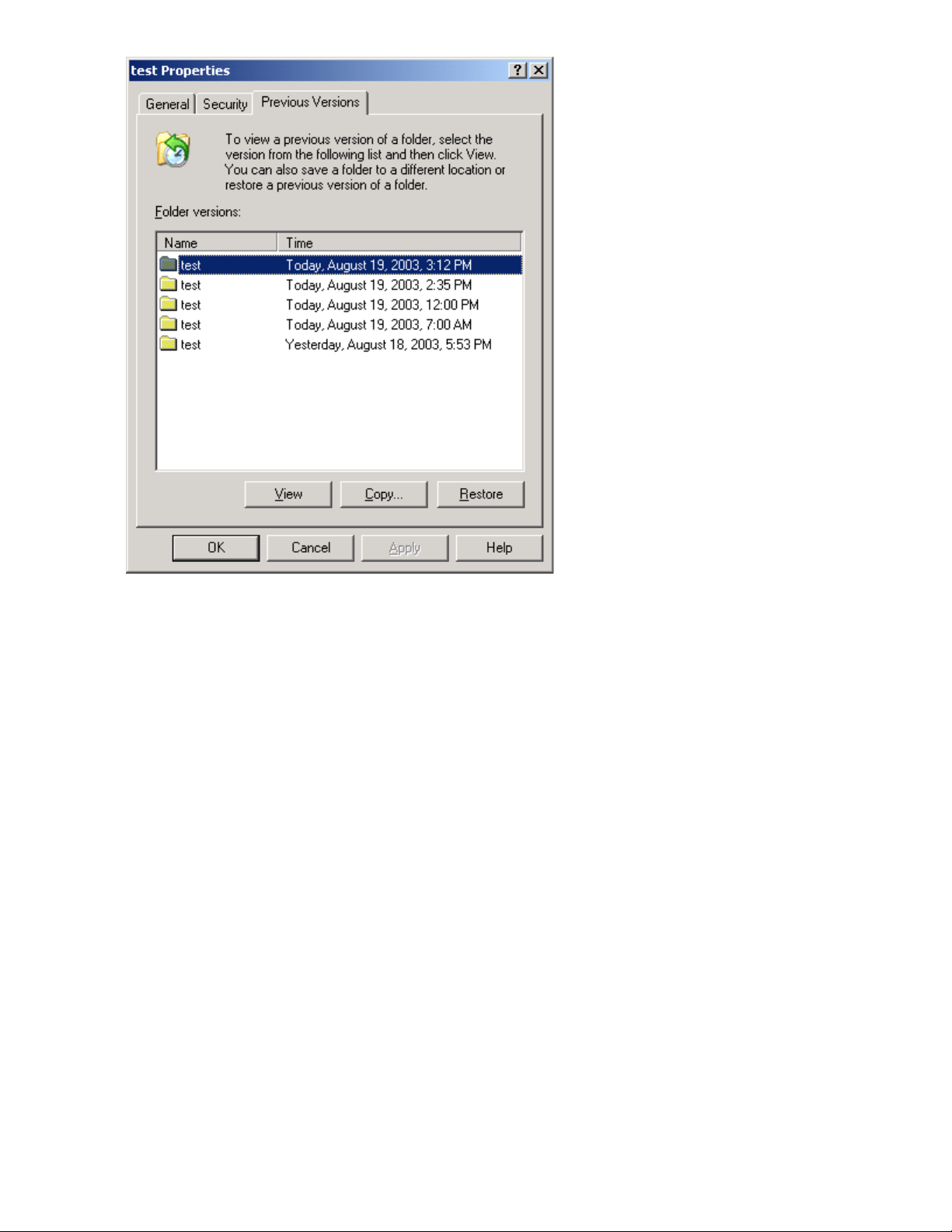
Figure 24 Recovering a deleted file or folder
.
Recovering an overwritten or corrupted file
Recovering an overwritten or corrupted file is easier than recovering a deleted file because the file
itself can be right-clicked instead of the folder. To recover an overwritten or corrupted file:
1. Right-click the overwritten or corrupted file, and then click Properties.
2. Click Previous Versions.
3. To view the old version, click View. To copy the old version to another location, click Copy... to
replace the current version with the older version, click Restore.
Recovering a folder
To recover a folder:
1. Position the cursor so that it is over a blank space in the folder to be recovered. If the cursor
hovers over a file, that file is selected.
2. Right-click, select Properties from the bottom of the menu, and then click the Previous Versions
tab.
3. Click either Copy... or Restore.
Clicking Restore enables the user to recover everything in that folder as well as all subfolders.
Clicking Restore does not delete any files.
File server management74
Page 75

Backup and shadow copies
Shadow copies are only available on the network via the client application, and only at a file or
folder level as opposed to the entire volume. Hence, the standard backup associated with a volume
backup will not work to back up the previous versions of the file system. To answer this particular
issue, shadow copies are available for backup in two situations. If the backup software in question
supports the use of shadow copies and can communicate with underlying block device, it is supported,
and the previous version of the file system will be listed in the backup application as a complete file
system snapshot. If the built-in backup application NTbackup is used, the backup software forces a
snapshot, and then uses the snapshot as the means for backup. The user is unaware of this activity
and it is not self-evident although it does address the issue of open files.
Shadow Copy Transport
Shadow Copy Transport provides the ability to transport data on a Storage Area Network (SAN).
With a storage array and a VSS-aware hardware provider, it is possible to create a shadow copy
on one server and import it on another server. This process, essentially “virtual” transport, is
accomplished in a matter of minutes, regardless of the size of the data.
A shadow copy transport can be used for a number of purposes, including:
• Tape backups
An alternative to traditional backup to tape processes is transport of shadow copies from the
production server onto a backup server, where they can then be backed up to tape. Like the other
two alternatives, this option removes backup traffic from the production server. While some backup
applications might be designed with the hardware provider software that enables transport, others
are not. The administrator should determine whether or not this functionality is included in the
backup application.
• Data mining
The data in use by a particular production server is often useful to different groups or departments
within an organization. Rather than add additional traffic to the production server, a shadow copy
of the data can be made available through transport to another server. The shadow copy can
then be processed for different purposes, without any performance impact on the original server.
The transport process is accomplished through a series of DISKRAID command steps:
1. Create a shadow copy of the source data on the source server (read-only).
2. Mask off (hide) the shadow copy from the source server.
3. Unmask the shadow copy to a target server.
4. Optionally, clear the read-only flags on the shadow copy.
The data is now ready to use.
Folder and share management
The storage system supports several file-sharing protocols, including DFS, NFS, FTP, HTTP, and
Microsoft SMB. This section discusses overview information as well as procedures for the setup and
management of the file shares for the supported protocols. Security at the file level and at the share
level is also discussed.
X1000 and X3000 Network Storage System 75
Page 76

NOTE:
Select servers can be deployed in a clustered or non-clustered configuration. This section discusses
share setup for a non-clustered deployment.
Folder management
Volumes and folders on any system are used to organize data. Regardless of system size, systematic
structuring and naming conventions of volumes and folders eases the administrative burden. Moving
from volumes to folders to shares increases the level of granularity of the types of data stored in the
unit and the level of security access allowed.
Folders can be managed using Server Manager. Tasks include:
• Accessing a specific volume or folder
• Creating a new folder
• Deleting a folder
• Modifying folder properties
• Creating a new share for a volume or folder
• Managing shares for a volume or folder
Managing file-level permissions
Security at the file level is managed using Windows Explorer.
File level security includes settings for permissions, ownership, and auditing for individual files.
To enter file permissions:
1. Using Windows Explorer, access the folder or file that needs to be changed, and then right-click
the folder.
File server management76
Page 77

2. Click Properties, and then click the Security tab.
Figure 25 Properties dialog box, Security tab
.
Several options are available on the Security tab:
• To add users and groups to the permissions list, click Add. Follow the dialog box instructions.
• To remove users and groups from the permissions list, highlight the desired user or group,
and then click Remove.
• The center section of the Security tab lists permission levels. When new users or groups are
added to the permissions list, select the appropriate boxes to configure the common file-access
levels.
X1000 and X3000 Network Storage System 77
Page 78
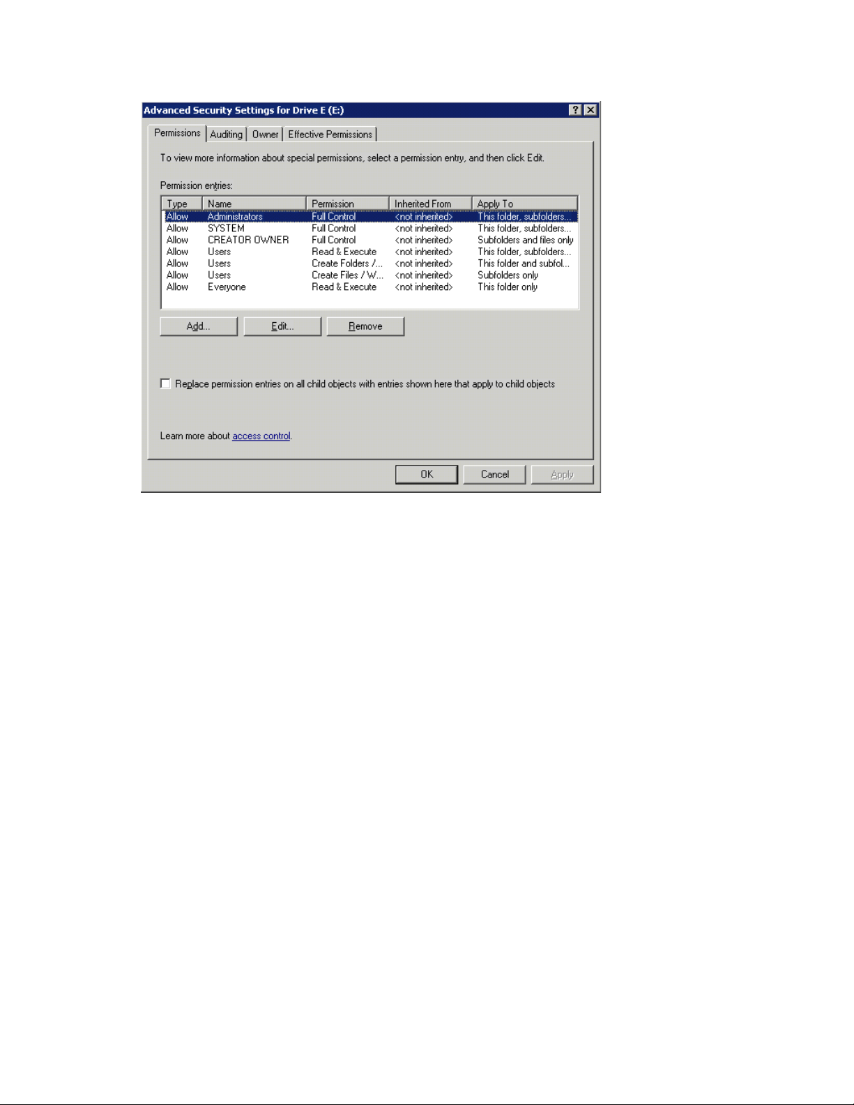
3. To modify ownership of files, or to modify individual file access level permissions, click Advanced.
Figure 26 illustrates the properties available on the Advanced Security Settings dialog box.
Figure 26 Advanced Security settings dialog box, Permissions tab
.
Other functionality available in the Advanced Security Settings dialog box is illustrated in Figure
26 and includes:
• Add a new user or group—Click Add, and then follow the dialog box instructions.
• Remove a user or group— Click Remove.
• Replace permission entries on all child objects with entries shown here that apply to child
objects—This allows all child folders and files to inherit the current folder permissions by default.
• Modify specific permissions assigned to a particular user or group—Select the desired user
or group, and then click Edit.
File server management78
Page 79
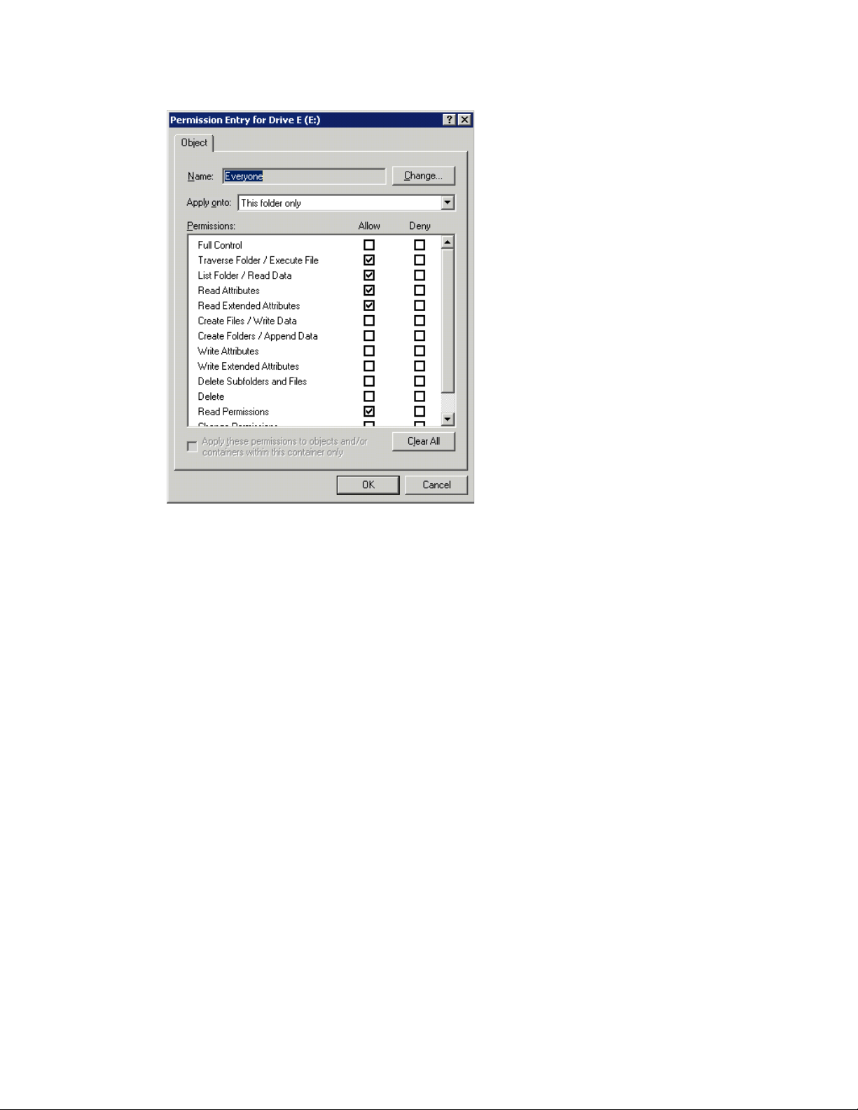
4. Enable or disable permissions by selecting the Allow box to enable permission or the Deny box
to disable permission. If neither box is selected, permission is automatically disabled. Figure 27
illustrates the Edit screen and some of the permissions.
Figure 27 User or group Permission Entry dialog box
.
Another area of the Advanced Security Settings is the Auditing tab. Auditing allows you to set
rules for the auditing of access, or attempted access, to files or folders. Users or groups can be
added, deleted, viewed, or modified through the Advanced Security Settings Auditing tab.
X1000 and X3000 Network Storage System 79
Page 80

Figure 28 Advanced Security Settings dialog box, Auditing tab
.
5. Click Add to display the Select User or Group dialog box.
Figure 29 Select User or Group dialog box
.
NOTE:
Click Advanced to search for users or groups.
6. Select the user or group.
File server management80
Page 81

7. Click OK.
The Auditing Entry dialog box is displayed.
Figure 30 Auditing Entry dialog box for folder name NTFS Test
.
8. Select the desired Successful and Failed audits for the user or group.
9. Click OK.
NOTE:
Auditing must be enabled to configure this information. Use the local Computer Policy Editor to
configure the audit policy on the storage system.
The Owner tab allows taking ownership of files. Typically, administrators use this area to take ownership
of files when the file ACL is incomplete or corrupt. By taking ownership, you gain access to the files,
and then manually apply the appropriate security configurations.
X1000 and X3000 Network Storage System 81
Page 82

Figure 31 Advanced Security Settings dialog box, Owner tab
.
The current owner of the file or folder is listed at the top of the screen. To take ownership:
1. Click the appropriate user or group in the Change owner to list.
2. If it is also necessary to take ownership of subfolders and files, enable the Replace owner on
subcontainers and objects box.
3. Click OK.
Share management
There are several ways to set up and manage shares. Methods include using Windows Explorer, a
command line interface, or Server Manger.
NOTE:
Select servers can be deployed in a clustered as well as a non-clustered configuration. This chapter
discusses share setup for a non-clustered deployment.
As previously mentioned, the file-sharing security model of the storage system is based on the NTFS
file-level security model. Share security seamlessly integrates with file security. In addition to discussing
share management, this section discusses share security.
Share considerations
Planning the content, size, and distribution of shares on the storage system can improve performance,
manageability, and ease of use.
File server management82
Page 83

The content of shares should be carefully chosen to avoid two common pitfalls: either having too many
shares of a very specific nature, or of having very few shares of a generic nature. For example, shares
for general use are easier to set up in the beginning, but can cause problems later. Frequently, a
better approach is to create separate shares with a specific purpose or group of users in mind.
However, creating too many shares also has its drawbacks. For example, if it is sufficient to create
a single share for user home directories, create a “homes” share rather than creating separate shares
for each user.
By keeping the number of shares and other resources low, the performance of the storage system is
optimized. For example, instead of sharing out each individual user's home directory as its own share,
share out the top-level directory and let the users map personal drives to their own subdirectory.
Defining Access Control Lists
The Access Control List (ACL) contains the information that dictates which users and groups have
access to a share, as well as the type of access that is permitted. Each share on an NTFS file system
has one ACL with multiple associated user permissions. For example, an ACL can define that User1
has read and write access to a share, User2 has read only access, and User3 has no access to the
share. The ACL also includes group access information that applies to every user in a configured
group. ACLs are also referred to as permissions.
Integrating local file system security into Windows domain environments
ACLs include properties specific to users and groups from a particular workgroup server or domain
environment. In a multidomain environment, user and group permissions from several domains can
apply to files stored on the same device. Users and groups local to the storage system can be given
access permissions to shares managed by the device. The domain name of the storage system supplies
the context in which the user or group is understood. Permission configuration depends on the network
and domain infrastructure where the server resides.
File-sharing protocols (except NFS) supply a user and group context for all connections over the
network. (NFS supplies a machine-based context.) When new files are created by those users or
machines, the appropriate ACLs are applied.
Configuration tools provide the ability to share permissions out to clients. These shared permissions
are propagated into a file system ACL, and when new files are created over the network, the user
creating the file becomes the file owner. In cases where a specific subdirectory of a share has different
permissions from the share itself, the NTFS permissions on the subdirectory apply instead. This method
results in a hierarchical security model where the network protocol permissions and the file permissions
work together to provide appropriate security for shares on the device.
NOTE:
Share permissions and file-level permissions are implemented separately. It is possible for files on a
file system to have different permissions from those applied to a share. When this situation occurs,
the file-level permissions override the share permissions.
Comparing administrative (hidden) and standard shares
CIFS supports both administrative shares and standard shares.
• Administrative shares are shares with a last character of $. Administrative shares are not included
in the list of shares when a client browses for available shares on a CIFS server.
X1000 and X3000 Network Storage System 83
Page 84

• Standard shares are shares that do not end in a $ character. Standard shares are listed whenever
a CIFS client browses for available shares on a CIFS server.
The storage system supports both administrative and standard CIFS shares. To create an administrative
share, end the share name with the $ character when setting up the share. Do not type a $ character
at the end of the share name when creating a standard share.
Managing shares
Shares can be managed using Server Manager. Tasks include:
• Creating a new share
• Deleting a share
• Modifying share properties
• Publishing in DFS
NOTE:
These functions can operate in a cluster on select servers, but should only be used for non-cluster-aware
shares. Use Cluster Administrator to manage shares for a cluster. The page will display cluster share
resources.
CAUTION:
Before deleting a share, warn all users to exit that share and confirm that no one is using that share.
File Server Resource Manager
File Server Resource Manager (FSRM) is a suite of tools that allows administrators to understand,
control, and manage the quantity and type of data stored on their servers. Some of the tasks you can
perform are:
• Quota management
• File screening management
• Storage reports
Server Manager provides access to FSRM tasks.
For procedures and methods beyond what are described below, see the online help.
Quota management
On the Quota Management node of the File Server Resource Manager snap-in, you can perform the
following tasks:
• Create quotas to limit the space allowed for a volume or folder and generate notifications when
the quota limits are approached or exceeded.
• Generate auto quotas that apply to all existing folders in a volume or folder, as well as to any
new subfolders created in the future.
• Define quota templates that can be easily applied to new volumes or folders and that can be used
across an organization.
File server management84
Page 85

File screening management
On the File Screening Management node of the File Server Resource Manager snap-in, you can
perform the following tasks:
• Create file screens to control the types of files that users can save and to send notifications when
users attempt to save blocked files.
• Define file screening templates that can be easily applied to new volumes or folders and that can
be used across an organization.
• Create file screening exceptions that extend the flexibility of the file screening rules.
Storage reports
On the Storage Reports node of the File Server Resource Manager snap-in, you can perform the
following tasks:
• Schedule periodic storage reports that allow you to identify trends in disk usage.
• Monitor attempts to save unauthorized files for all users or a selected group of users.
• Generate storage reports instantly.
Other Windows disk and data management tools
When you install certain tools, such as Windows Support Tools or Windows Resource Kit Tools,
information about these tools might appear in Help and Support Center. To see the tools that are
available to you, look in the Help and Support Center under Support Tasks, click Tools, and then click
Tools by Category.
NOTE:
The Windows Support Tools and Windows Resource Kit Tools, including documentation for these
tools, are available in English only. If you install them on a non-English language operating system
or on an operating system with a Multilingual User Interface Pack (MUI), you see English content
mixed with non-English content in Help and Support Center. To see the tools that are available to
you, click Start, click Help and Support Center, and then, under Support Tasks, click Tools.
Additional information and references for file services
Backup
HP recommends that you back up the print server configuration whenever a new printer is added to
the network and the print server configuration is modified.
HP StorageWorks Library and Tape Tools
HP StorageWorks Library and Tape Tools (L&TT) provides functionality for firmware downloads,
verification of device operation, maintenance procedures, failure analysis, corrective service actions,
and some utility functions. It also provides seamless integration with HP hardware support by generating
and e-mailing support tickets that deliver a snapshot of the storage system.
X1000 and X3000 Network Storage System 85
Page 86

Antivirus
For more information, and to download the utility, see the StorageWorks L&TT web site at http://
h18006.www1.hp.com/products/storageworks/ltt.
The server should be secured by installing the appropriate antivirus software.anything
File server management86
Page 87

6 Cluster administration
HP StorageWorks X3000 Network Storage Systems support clustering; HP StorageWorks X1000
Network Storage Systems do not.
One important feature of HP StorageWorks X3000 Network Storage System models is that they can
operate as a single node or as a cluster. This chapter discusses cluster installation and cluster
management issues.
For information about installing, setting up, and configuring HP's High Availability (HA) Shared
Storage Solution bundles (the HP StorageWorks X3410 1-Node Network Storage System, HP
StorageWorks X3420 2-Node Network Storage System, and HP StorageWorks X3820 2-Node
Network Storage System), go to http://www.hp.com/go/nas, click Entry File Services, click HP
Support & Drivers, select your product, click Manuals, and then click the link for HP StorageWorks
X1000 and X3000 Network Storage Gateway installation instructions.
Cluster overview
Up to eight server nodes can be connected to each other and deployed as a no single point of failure
(NSPOF) cluster. Utilizing a private network allows communication amongst themselves in order to
track the state of each cluster node. Each node sends out periodic messages to the other nodes; these
messages are called heartbeats. If a node stops sending heartbeats, the cluster service fails over any
resources that the node owns to another node. For example, if the node that owns the Quorum disk
is shut down for any reason, its heartbeat stops. The other nodes detect the lack of the heartbeat and
another node takes over ownership of the Quorum disk and the cluster.
Clustering servers greatly enhances the availability of file serving by enabling file shares to fail over
to additional storage systems if problems arise. Clients see only a brief interruption of service as the
file share resource transitions from one server node to the other.
X1000 and X3000 Network Storage System 87
Page 88

Figure 32 Storage system cluster diagram
.
Cluster terms and components
Nodes
The most basic parts of a cluster are the servers, referred to as nodes. A server node is any individual
server in a cluster, or a member of the cluster.
Resources
Hardware and software components that are managed by the cluster service are called cluster
resources. Cluster resources have three defining characteristics:
• They can be brought online and taken offline.
• They can be managed in a cluster.
• They can be owned by only one node at a time.
Examples of cluster resources are IP addresses, network names, physical disk resources, and file
shares. Resources represent individual system components. These resources are organized into groups
and managed as a group. Some resources are created automatically by the system and other resources
must be set up manually. Resource types include:
• IP address resource
• Cluster name resource
• Cluster quorum disk resource
• Physical disk resource
• Virtual server name resources
Cluster administration88
Page 89

• CIFS file share resources
• NFS file share resources
• FTP file share resources
• iSCSI resources
Cluster groups
Cluster resources are placed together in cluster groups. Groups are the basic unit of failover between
nodes. Resources do not fail over individually; they fail over with the group in which they are contained.
Virtual servers
A virtual server is a cluster group that consists of a static IP Address resource and a Network Name
resource. Several virtual servers can be created. By assigning ownership of the virtual servers to the
different server nodes, the processing load on the storage systems can be distributed between the
nodes of a cluster.
The creation of a virtual server allows resources dependent on the virtual server to fail over and fail
back between the cluster nodes. Cluster resources are assigned to the virtual server to ensure
non-disruptive service of the resources to the clients.
Failover and failback
Failover of cluster groups and resources happens:
• When a node hosting the group becomes inactive.
• When all of the resources within the group are dependent on one resource, and that resource
fails.
• When an administrator forces a failover.
A resource and all of its dependencies must be located in the same group so that if a resource fails
over, all of its dependent resources fail over.
When a resource is failed over, the cluster service performs certain procedures. First, all of the resources
are taken offline in an order defined by the resource dependencies. Secondly, the cluster service
attempts to transfer the group to the next node on the preferred owner's list. If the transfer is successful,
the resources are brought online in accordance with the resource dependency structure.
The system failover policy defines how the cluster detects and responds to the failure of individual
resources in the group. After a failover occurs and the cluster is brought back to its original state,
failback can occur automatically based on the policy. After a previously failed node comes online,
the cluster service can fail back the groups to the original host. The failback policy must be set before
the failover occurs so that failback works as intended.
Quorum disk
Each cluster must have a shared disk called the Quorum disk. The Quorum disk is the shared storage
used by the cluster nodes to coordinate the internal cluster state. This physical disk in the common
cluster disk array plays a critical role in cluster operations. The Quorum disk offers a means of persistent
storage. The disk must provide physical storage that can be accessed by all nodes in the cluster. If a
node has control of the quorum resource upon startup, it can initiate the cluster. In addition, if the
node can communicate with the node that owns the quorum resource, it can join or remain in the
cluster.
The Quorum disk maintains data integrity by:
X1000 and X3000 Network Storage System 89
Page 90

• Storing the most current version of the cluster database
• Guaranteeing that only one set of active communicating nodes is allowed to operate as a cluster
Cluster concepts
Figure 33 illustrates a typical cluster configuration with the corresponding storage elements. The
diagram progresses from the physical disks to the file shares, showing the relationship between both
the cluster elements and the physical devices underlying them. While the diagram only illustrates two
nodes, the same concepts apply for multi-node deployments.
Figure 33 Cluster concepts diagram
.
Sequence of events for cluster resources
The sequence of events in the diagram includes:
1. Physical disks are combined into RAID arrays and LUNs.
2. LUNS are designated as basic disks, formatted, and assigned a drive letter via Disk Manager.
Cluster administration90
Page 91

3. Physical Disk resources are created for each basic disk inside Cluster Administrator.
4. Directories and folders are created on assigned drives.
5. Cluster components (virtual servers, file shares) are created, organized in groups, and placed
within the folders using Cluster Administrator exclusively.
Hierarchy of cluster resource components
Figure 33 depicts the cluster resource hierarchy as follows:
• Physical Disk resources are placed in a cluster group and relate to the basic disk. When a Physical
Disk resource is created through Cluster Administrator, the resource should be inserted into an
existing cluster group or a corresponding group should be created for the resource to reside in.
• File share resources are placed in a group and relate to the actual directory on the drive on which
the share is being created.
• An IP Address resource is formed in the group and relates to the IP address by which the group's
virtual server is identified on the network.
• A Network Name resource is formed in the group and relates to the name published on the network
by which the group is identified.
• The Group is owned by one of the nodes of the cluster, but may transition to the other nodes during
failover conditions.
The diagram illustrates a cluster containing two nodes. Each node has ownership of one group.
Contained within each group are file shares that are known on the network by the associated Network
Name and IP address. In the specific case of Node1, file share Eng1 relates to E:\Eng1. This file
share is known on the network as \\Fileserver1\Eng1 with an IP address of 172.18.1.99.
For cluster resources to function properly, two very important requirements should be adhered to:
• Dependencies between resources of a group must be established. Dependencies determine the
order of startup when a group comes online. In the above case, the following order should be
maintained:
1. File Share—Dependent on Physical Disk Resource and Network Name
2. Network Name—Dependent on IP Address
Failure to indicate the dependencies of a resource properly may result in the file share attempting
to come online prior to the physical disk resource being available, resulting in a failed file share.
• Groups should have a Network Name resource and an IP Address resource. These resources are
used by the network to give each group a virtual name. Without this virtual reference to the group,
the only way to address a share that is created as a clustered resource is by node name. Physical
node names do not transition during a failover, whereas virtual names do.
For example, if a client maps a network share to \\Node1\Eng1 instead of \\Fileserver1\Eng1,
when Node1 fails and Node2 assumes ownership, the map will become invalid because the reference
in the map is to \\Node1. If the map were created to the virtual name and Node1 were to fail, the
map would still exist when the group associated with Eng1 failed over to Node2.
The previous diagram is an example and is not intended to imply limitations of a single group or
node. Groups can contain multiple physical disks resources and file shares and nodes can have
multiple groups, as shown by the group owned by Node2.
Cluster planning
Requirements for taking advantage of clustering include:
X1000 and X3000 Network Storage System 91
Page 92

• Storage planning
• Network planning
• Protocol planning
Storage planning
For clustering, a basic disk must be designated for the cluster and configured as the Quorum disk.
Additional basic disks are presented to each cluster node for data storage as physical disk resources.
The physical disk resources are required for the basic disks to successfully work in a cluster environment,
protecting it from simultaneous access from each node.
The basic disk must be added as a physical disk resource to an existing cluster group or a new cluster
group needs to be created for the resource. Cluster groups can contain more than one physical disk
resource depending on the site-specific requirements.
NOTE:
The LUN underlying the basic disk should be presented to only one node of the cluster using selective
storage presentation or SAN zoning, or having only one node online at all times until the physical
resource for the basic disk is established.
In preparing for the cluster installation:
• All shared disks, including the Quorum disk, must be accessible from all nodes. When testing
connectivity between the nodes and the LUN, only one node should be given access to the LUN
at a time.
• All shared disks must be configured as basic (not dynamic).
• All partitions on the disks must be formatted as NTFS.
Network planning
Clusters require more sophisticated networking arrangements than a stand alone storage system. A
Windows NT domain or Active Directory domain must be in place to contain the cluster names, virtual
server names, and user and group information. A cluster cannot be deployed into a non domain
environment.
All cluster deployments have at least six network addresses and four network names:
• The cluster name (Unique NETBIOS Name) and IP address
• Node A's name and IP address
• Node B's name and IP address
• At least one virtual server name and IP address for virtual server A
• Cluster Interconnect static IP addresses for Node A and Node B
In multi-node deployments, additional network addresses are required. For each additional node,
three static IP addresses are required.
Virtual names and addresses are the only identification used by clients on the network. Because the
names and addresses are virtual, their ownership can transition from one node to the other during a
failover, preserving access to the resources in the cluster group.
A cluster uses at least two network connections on each node:
Cluster administration92
Page 93

• The private cluster interconnect or “heartbeat” crossover cable connects to one of the network
ports on each cluster node. In more than two node deployments, a private VLAN on a switch or
hub is required for the cluster interconnect.
• The public client network subnet connects to the remaining network ports on each cluster node.
The cluster node names and virtual server names have IP addresses residing on these subnets.
NOTE:
If the share is to remain available during a failover, each cluster node must be connected to the same
network subnet. It is impossible for a cluster node to serve the data to a network to which it is not
connected.
Protocol planning
Not all file sharing protocols can take advantage of clustering. If a protocol does not support clustering,
it will not have a cluster resource and will not failover with any cluster group. In the case of a failover,
a client cannot use the virtual name or virtual IP address to access the share since the protocol cannot
failover with the cluster group. The client must wait until the initial node is brought back online to
access the share.
HP recommends placing cluster aware and non cluster aware protocols on different file shares.
Table 14 Sharing protocol cluster support
iSCSI
Client VariantProtocol
Windows 2000
Windows 95
Windows 98
Windows ME
Linux
Standards-based iSCSI
initiator
Cluster Aware (supports failover)
Supported on cluster
nodes
YesYesWindows NTCIFS/SMB
YesYesUNIXNFS
YesNoWebHTTP
YesYesManyFTP
YesNoNovellNCP
NoNoAppleAppleTalk
YesYes
X1000 and X3000 Network Storage System 93
Page 94

NOTE:
AppleTalk is not supported on clustered disk resources. AppleTalk requires local memory for volume
indexing. On failover events, the memory map is lost and data corruption can occur.
Preparing for cluster installation
This section provides the steps necessary to cluster HP StorageWorks X3000 Network Storage Systems.
Before beginning installation
Confirm that the following specifications have been met before proceeding:
• The Quorum disk has been created from shared storage and is at least 50 MB. (500 MB is recom-
mended.) Additional LUNs may also be presented for use as shared disk resources.
• Cluster configurations should be deployed with dual data paths for high availability. Dual data
paths from each node enable a path failure to occur that does not force the failover of the node.
Clusters can be configured with single path, but if a failure in the path does occur, all of the node
resources will be failed to the non-affected node.
Using multipath data paths for high availability
HP recommends that cluster configurations be deployed with dual data paths for high availability.
Clusters can be configured with single path, but if a failure in the path occurs, all of the node resources
will be failed to the non-affected node. Pathing software is required in configurations where multipathing
to the storage is desired or required. Multipathing software allows for datapath failure to occur without
forcing a node failover.
Checklists for cluster server installation
These checklists assist in preparing for installation. Step-by-step instructions begin after the checklists.
Network requirements
• A unique NetBIOS cluster name
• For each node deployed in the cluster the following static IP addresses are required:
• One for the network adapters on the private network
• One for the network adapters on the public network
• One for the virtual server itself
A single static cluster IP address is required for the entire cluster.
• A domain user account for Cluster service (all nodes must be members of the same domain)
• Each node should have at least two network adapters—one for connection to the public network
and the other for the node-to-node private cluster network. If only one network adapter is used for
both connections, the configuration is unsupported. A separate private network adapter is required
for HCL certification.
Cluster administration94
Page 95

Shared disk requirements
NOTE:
Do not allow more than one node access the shared storage devices at the same time until Cluster
service is installed on at least one node and that node is online. This can be accomplished through
selective storage presentation, SAN zoning, or having only one node online at all times.
• All shared disks, including the Quorum disk, must be accessible from all nodes. When testing
connectivity between the nodes and the LUN, only one node should be given access to the LUN
at a time.
• All shared disks must be configured as basic (not dynamic).
• All partitions on the disks must be formatted as NTFS.
Cluster installation
During the installation process, nodes are shut down and rebooted. These steps guarantee that the
data on disks that are attached to the shared storage bus is not lost or corrupted. This can happen
when multiple nodes try to simultaneously write to the same disk that is not yet protected by the cluster
software.
Use Table 15 to determine which nodes and storage devices should be presented during each step.
Table 15 Power sequencing for cluster installation
Setting up networks
Setting up
shared disks (including the Qurom disk)
Verifying disk
configuration
Configuring the
first node
Configuring additional nodes
Node 1Step
Additional
Nodes
OnOn
Not
Presented
PresentedOffOn
PresentedOnOff
PresentedOffOn
PresentedOnOn
PresentedOnOnPost-installation
CommentsStorage
Verify that all storage devices on the
shared bus are not presented; Power on
all nodes.
Shut down all nodes. Present the shared
storage, then power on the first node.
Shut down first node, power on next
node. Repeat this process for all cluster
nodes.
Shut down all nodes; power on the first
node.
Power on the next node after the first
node is successfully configured. Complete this process for all cluster nodes.
At this point all cluster nodes should be
on.
To configure the Cluster service on the storage system, an account must have administrative permissions
on each node.
X1000 and X3000 Network Storage System 95
Page 96

Setting up networks
Verify that all network connections are correct, with private network adapters connected to other
private network adapters only, and public network adapters connected to the public network.
Configuring the private network adapter
The following procedures are best practices provided by Microsoft and should be configured on the
private network adapter.
• On the General tab of the private network adapter, ensure that only TCP/IP is selected.
• Ensure that the Register this connection's address in DNS is not selected in the DNS tab under
advanced settings for Internet Protocol (TCP/IP) Properties.
• In all cases, set static IP addresses for the private network connector.
Configuring the public network adapter
While the public network adapter's IP address can be automatically obtained if a DHCP server is
available, this is not recommended for cluster nodes. HP strongly recommends setting static IP addresses
for all network adapters in the cluster, both private and public. If IP addresses are obtained though
DHCP, access to cluster nodes could become unavailable if the DHCP server goes down. If DHCP
must be used for the public network adapter, use long lease periods to assure that the dynamically
assigned lease address remains valid even if the DHCP service is temporarily lost. Keep in mind that
Cluster service recognizes only one network interface per subnet.
Renaming the local area connection icons
HP recommends changing the names of the network connections for clarity. The naming helps identify
a network and correctly assign its role. For example, “Cluster interconnect” for the private network
and “Public connection” for the public network.
Verifying connectivity and name resolution
To verify name resolution, ping each node from a client using the node's machine name instead of
its IP address.
Verifying domain membership
All nodes in the cluster must be members of the same domain and able to access a domain controller
and a DNS Server.
Setting up a cluster account
The Cluster service requires a domain user account under which the Cluster service can run. This user
account must be created before installing Cluster service, because setup requires a user name and
password. This user account should be a unique domain account created specifically to administer
this cluster. This user account will need to be granted administrator privileges.
About the Quorum disk
HP makes the following Quorum disk recommendations:
Cluster administration96
Page 97

• Dedicate a separate disk resource for a Quorum disk. Because the failure of the Quorum disk
would cause the entire cluster to fail, HP strongly recommends that the disk resource be a RAID 1
configuration.
• Create a partition with a minimum of 50 megabytes (MB) to be used as a Quorum disk. HP recom-
mends a Quorum disk be 500 MB.
HP recommends assigning the drive letter Q for the Quorum disk. It is also helpful to label the volume
Quorum.
NOTE:
It is possible to change the Quorum disk by clicking the Quorum button. This displays a list of available
disks that can be used for the Quorum disk. Select the appropriate disk, and then click OK to continue.
Configuring shared disks
Use the Windows Disk Management utility to configure additional shared disk resources. Verify that
all shared disks are formatted as NTFS and are designated as Basic.
Additional shared disk resources are automatically added into the cluster as physical disk resources
during the installation of cluster services.
Verifying disk access and functionality
Write a file to each shared disk resource to verify functionality.
At this time, shut down the first node, power on the next node and repeat the Verifying Disk Access
and Functionality step above for all cluster nodes. When it has been verified that all nodes can read
and write from the disks, turn off the cluster nodes and power on the first, and then continue with this
guide.
Configuring cluster service software
Cluster Administrator (cluadmin) provides the ability to manage, monitor, create and modify clusters
and cluster resources.
Using Cluster Administrator
Cluster Administrator shows information about the groups and resources on all of your clusters and
specific information about the clusters themselves. A copy of Cluster Administrator is automatically
installed on a cluster node when the Cluster service is installed.
Creating a cluster
During the creation of the cluster, Cluster Administrator will analyze and verify the hardware and
software configuration and identify potential problems. A comprehensive and easy-to-read report is
created, listing any potential configuration issues before the cluster is created.
Some issues that can occur are:
• No shared disk for the Quorum disk. A shared disk must be created with a NTFS partition at least
50 MB in size.
X1000 and X3000 Network Storage System 97
Page 98

• Use of DHCP addresses for network connections. All Network adapters must be configured with
static IP addresses in a cluster configuration.
• File Services for Macintosh and Service for NetWare are not supported in a cluster configuration.
• Dynamic Disks are not supported in a cluster configuration.
• Errors appear on a network adapter that is not configured or does not have an active link. If the
network adapter is not going to be used it should be disabled.
Adding nodes to a cluster
Only the Quorum disk should be accessible by the new node while the new node is not a member
of the cluster. The new node should not have access to the other LUNs in the cluster until after it has
joined the cluster. After the node has joined the cluster, the LUNs may be presented to the new node.
Move the physical disk resources over to the new node to confirm functionality.
CAUTION:
Presenting other LUNs to the non-clustered system could lead to data corruption.
Geographically dispersed clusters
Cluster nodes can be geographically dispersed to provide an additional layer of fault tolerance.
Geographically dispersed clusters are also referred to as stretched clusters.
The following rules must be followed with geographically dispersed clusters:
• A network connection with latency of 500 milliseconds or less ensures that cluster consistency can
be maintained. If the network latency is over 500 milliseconds, the cluster consistency cannot be
easily maintained.
• All nodes must be on the same subnet.
Cluster groups and resources, including file shares
The Cluster Administrator tool provides complete online help for all cluster administration activities.
Cluster resources include administrative types of resources as well as file shares. The following
paragraphs include overview and planning issues for cluster groups, cluster resources, and clustered
file shares.
Creating and managing these resources and groups must be managed through Cluster Administrator.
Cluster group overview
A default cluster group is automatically created when the cluster is first created. This default cluster
group contains an Internet Protocol (IP) Address resource, a Network Name resource, and the Quorum
disk resource. When the new cluster is created, the (IP) address and the cluster name that were
specified during setup are set up as the IP address and network name of this default cluster group.
CAUTION:
Do not delete or rename the Cluster Group or IP Address. Doing so results in losing the cluster and
requires reinstallation of the cluster.
Cluster administration98
Page 99

When creating groups, the administrator's first priority is to gain an understanding of how to manage
the groups and their resources. Administrators may choose to create a resource group and a virtual
server for each node that will contain all resources owned by that node, or the administrator may
choose to create a resource group and virtual server for each physical disk resource. Additionally,
the administrator should try to balance the load of the groups and their resources on the cluster
between the nodes.
Node-based cluster groups
Creating only one resource group and one virtual server for each node facilitates group and resource
administration. This setup allows administrators to include all file share resources under one group.
Clients access all of the resources owned by one node through a virtual server name.
In node-based cluster groups, each group has its own network name and IP address. The administrator
decides on which node to place each physical disk resource. This configuration provides a very coarse
level of granularity. All resources within a group must remain on the same node. Only two IP addresses
and network names are required. This configuration creates less overhead for resource and network
administration. A possible disadvantage of this approach is that the resource groups can potentially
grow large when many file shares are created.
Load balancing
The creation of separate cluster groups for each virtual server provides more flexibility in balancing
the processing load on the cluster between the two nodes. Each cluster group can be assigned to a
cluster node with the preferred owner parameter. For example, if there are two cluster groups, the
cluster could be set up to have the first cluster group owned by Node A and the second cluster group
owned by Node B. This allows the network load to be handled by both devices simultaneously. If
only one cluster group exists, it can only be owned by one node and the other node would not serve
any network traffic.
File share resource planning issues
CIFS and NFS are cluster-aware protocols that support the Active/Active cluster model, allowing
resources to be distributed and processed on both nodes at the same time. For example, some NFS
file share resources can be assigned to a group owned by a virtual server for Node A and additional
NFS file share resources can be assigned to a group owned by a virtual server for Node B.
Configuring the file shares as cluster resources provides for high availability of file shares. Because
the resources are placed into groups, ownership of the files can easily move from one node to the
other, as circumstances require. If the cluster node owning the group of file shares should be shut
down or fail, the other node in the cluster will begin sharing the directories until the original owner
node is brought back on line. At that time, ownership of the group and its resources can be brought
back to the original owner node.
Resource planning
1. Create a cluster group for each node in the cluster with an IP address resource and a network
name resource.
Cluster resource groups are used to balance the processing load on the servers. Distribute
ownership of the groups between the virtual servers.
X1000 and X3000 Network Storage System 99
Page 100

2. For NFS environments, configure the NFS server.
NFS specific procedures include entering audit and file lock information as well as setting up
client groups and user name mappings. These procedures are not unique to a clustered deployment
and are detailed in the Microsoft Services for NFS section within the “Other network file and
print services” chapter. Changes to NFS setup information are automatically replicated to all
nodes in a cluster.
3. Create the file share resources.
4. Assign ownership of the file share resources to the resource groups.
a. Divide ownership of the file share resource between the resource groups, which are in turn
distributed between the virtual servers, for effective load balancing.
b. Verify that the physical disk resource for this file share is also included in this group.
c. Verify that the resources are dependent on the virtual servers and physical disk resources
from which the file share was created.
Permissions and access rights on share resources
File Share and NFS Share permissions must be managed using the Cluster Administrator tool versus
the individual shares on the file system themselves via Windows Explorer. Administering them through
the Cluster Administrator tool allows the permissions to migrate from one node to other. In addition,
permissions established using Explorer are lost after the share is failed or taken offline.
NFS cluster-specific issues
For convenience, all suggestions are listed below:
• Back up user and group mappings.
To avoid loss of complex advanced mappings in the case of a system failure, back up the mappings
whenever the mappings have been edited or new mappings have been added.
• Map consistently.
Groups that are mapped to each other should contain the same users and the members of the
groups should be properly mapped to each other to ensure proper file access.
• Map properly.
• Valid UNIX users should be mapped to valid Windows users.
• Valid UNIX groups should be mapped to valid Windows groups.
• Mapped Windows user must have the “Access this computer from the Network privilege” or
the mapping will be squashed.
• The mapped Windows user must have an active password, or the mapping will be squashed.
• In a clustered deployment, create user name mappings using domain user accounts.
Because the security identifiers of local accounts are recognized only by the local server, other
nodes in the cluster will not be able to resolve those accounts during a failover. Do not create
mappings using local user and group accounts.
• In a clustered deployment, administer user name mapping on a computer that belongs to a trusted
domain.
If NFS administration tasks are performed on a computer that belongs to a domain that is not
trusted by the domain of the cluster, the changes are not properly replicated among the nodes in
the cluster.
• In a clustered deployment, if PCNFS password and group files are being used to provide user
and group information, these files must be located on each node of the system.
Cluster administration100
 Loading...