

Page 1

HPE B-series 16Gb SAN Switches Hardware Reference Guide
Abstract
This document provides information on installing, configuring, and maintaining the HPE
StoreFabric SN6500B 16Gb Fibre Channel Switch, the HPE SN6000B 16Gb Fibre Channel
Switch, the HPE SN3000B 16Gb Fibre Channel Switch, and the StoreFabric SN4000B SAN
Extension Switch. It is intended for system administrators and technicians with knowledge of
SANs and HPE FC switches.
Part Number: 5200-2547
Published: July 2017
Edition: 8
Page 2

Notices
The information contained herein is subject to change without notice. The only warranties for Hewlett
Packard Enterprise products and services are set forth in the express warranty statements accompanying
such products and services. Nothing herein should be construed as constituting an additional warranty.
Hewlett Packard Enterprise shall not be liable for technical or editorial errors or omissions contained
herein.
Confidential computer software. Valid license from Hewlett Packard Enterprise required for possession,
use, or copying. Consistent with FAR 12.211 and 12.212, Commercial Computer Software, Computer
Software Documentation, and Technical Data for Commercial Items are licensed to the U.S. Government
under vendor's standard commercial license.
Links to third-party websites take you outside the Hewlett Packard Enterprise website. Hewlett Packard
Enterprise has no control over and is not responsible for information outside the Hewlett Packard
Enterprise website.
Acknowledgments
Microsoft® and Windows® are either registered trademarks or trademarks of Microsoft Corporation in the
United States and/or other countries.
UNIX® is a registered trademark of The Open Group.
Page 3

Contents
HPE 16Gb FC switches...........................................................................6
HPE StoreFabric SN6500B 16Gb FC Switch............................................................................... 6
Overview............................................................................................................................ 6
Platform capabilities........................................................................................................... 6
Platform components......................................................................................................... 7
Port side of the switch........................................................................................................ 8
Nonport side of the switch..................................................................................................8
Software options.................................................................................................................9
ISL Trunking............................................................................................................ 9
Hardware options............................................................................................................. 10
SFP transceivers................................................................................................... 11
HPE SN6000B 16Gb FC Switch................................................................................................. 11
Overview...........................................................................................................................11
Platform capabilities......................................................................................................... 12
Platform components....................................................................................................... 13
Port side of the switch...................................................................................................... 13
Nonport side of the switch................................................................................................14
Software options.............................................................................................................. 14
ISL Trunking.......................................................................................................... 15
Hardware options............................................................................................................. 15
SFP transceivers................................................................................................... 16
HPE SN3000B 16Gb FC Switch................................................................................................. 16
Overview.......................................................................................................................... 16
Platform capabilities......................................................................................................... 16
Platform components....................................................................................................... 17
Port side of the switch...................................................................................................... 18
Nonport side of the switch................................................................................................18
Software options.............................................................................................................. 19
ISL Trunking.......................................................................................................... 19
Hardware options............................................................................................................. 20
SFP transceivers................................................................................................... 20
HPE StoreFabric SN4000B SAN Extension Switch....................................................................20
Overview.......................................................................................................................... 20
Platform capabilities......................................................................................................... 21
Platform components....................................................................................................... 21
Port side of the switch...................................................................................................... 22
Nonport side of the switch................................................................................................22
Software options.............................................................................................................. 22
Hardware options............................................................................................................. 23
Transceivers .........................................................................................................23
Installing and configuring HPE 16Gb FC switches............................24
Accessories.................................................................................................................................24
Installation and safety considerations......................................................................................... 24
Electrical considerations.................................................................................................. 24
Environmental considerations.......................................................................................... 25
Cabling considerations.....................................................................................................25
Installing the switch.....................................................................................................................26
Items required for installation........................................................................................... 26
Contents 3
Page 4

Installing the HPE StoreFabric SN6500B 16Gb FC Switch in a rack using the Rack
Mount Kit.......................................................................................................................... 26
Securing the switch to the outer rails.................................................................... 31
Installing the HPE SN6000B 16Gb FC and HPE SN3000B 16Gb FC switches in a
rack using the Rack Mount Kit......................................................................................... 32
Installing the HPE StoreFabric SN4000B SAN Extension Switch ...................................37
Securing the switch to the outer rails.................................................................... 40
Installing a standalone switch.......................................................................................... 42
Setting up the switch...................................................................................................................43
Connecting the serial cable.........................................................................................................43
Logging in to the serial console port........................................................................................... 44
Setting the IP address.................................................................................................................44
Using DHCP to set the IP address...................................................................................44
Setting a static IP address............................................................................................... 44
Setting the date and time............................................................................................................ 45
Setting the date................................................................................................................ 45
Setting the time zone....................................................................................................... 45
Synchronizing local time........................................................................................46
Synchronizing local time using NTP......................................................................47
Configuring the zones and selecting devices..............................................................................47
Connecting devices.....................................................................................................................47
Setting switch features................................................................................................................49
Switch status policy.....................................................................................................................49
Changing the switch name and chassis name............................................................................49
Verifying the configuration...........................................................................................................50
Backing up the configuration.......................................................................................................50
Installing and activating Port Upgrade licenses.......................................................................... 50
Fabric OS Native and AG modes................................................................................................51
Disabling and enabling AG mode.....................................................................................52
Enabling AG mode................................................................................................ 52
Disabling AG mode................................................................................................52
Operating HPE 16Gb FC switches.......................................................54
Powering the switch on and off................................................................................................... 54
LEDs........................................................................................................................................... 54
POST and boot specifications.....................................................................................................61
POST................................................................................................................................61
Boot..................................................................................................................................62
Switch maintenance....................................................................................................................62
Diagnostic tests................................................................................................................62
Switch management................................................................................................................... 62
FRU removal and replacement................................................................................................... 63
Replacing the HPE StoreFabric SN6500B 16Gb FC Switch or the HPE StoreFabric
SN4000B SAN Extension Switch power supply ..............................................................63
Determining the need to replace a power supply.................................................. 64
Before beginning the power supply replacement.................................................. 64
Replacing a power supply..................................................................................... 65
Replacing an HPE StoreFabric SN6500B 16Gb FC Switch or an HPE StoreFabric
SN4000B SAN Extension Switch fan .............................................................................. 68
Determining the need to replace a fan ................................................................. 69
Replacing an HPE StoreFabric SN6500B 16Gb FC Switch or an HPE
StoreFabric SN4000B SAN Extension Switch fan ................................................69
Replacing the HPE SN6000B or SN3000B 16Gb FC Switch power supply and fan
assembly.......................................................................................................................... 71
Determining the status of a power supply and fan assembly................................ 72
4 Contents
Page 5

Removing a power supply and fan assembly........................................................72
Installing a power supply and fan assembly..........................................................73
Support and other resources...............................................................75
Accessing Hewlett Packard Enterprise Support......................................................................... 75
Accessing updates......................................................................................................................75
Websites..................................................................................................................................... 75
Customer self repair....................................................................................................................76
Remote support.......................................................................................................................... 76
Documentation feedback............................................................................................................ 76
Specifications........................................................................................77
Physical specifications................................................................................................................ 77
Facility requirements...................................................................................................................78
Power supply specifications........................................................................................................78
Environmental requirements....................................................................................................... 80
General specifications.................................................................................................................82
Data transmission ranges........................................................................................................... 84
Memory specifications.................................................................................................................87
FC port specifications..................................................................................................................87
Serial port specifications............................................................................................................. 87
AG default port mapping............................................................................................................. 88
Warranty and regulatory information..................................................90
Warranty information...................................................................................................................90
Regulatory information................................................................................................................90
Belarus Kazakhstan Russia marking............................................................................... 90
Turkey RoHS material content declaration.......................................................................91
Ukraine RoHS material content declaration..................................................................... 91
Electrostatic discharge and grounding recommendations.............. 92
Electrostatic discharge recommendations.................................................................................. 92
Grounding methods.................................................................................................................... 92
Glossary.................................................................................................93
.................................................................................................................................................... 93
Contents 5
Page 6

HPE 16Gb FC switches
This chapter provides general information about the HPE StoreFabric SN6500B 16Gb FC Switch, HPE
SN6000B 16Gb FC Switch, HPE SN3000B 16Gb FC Switch, and HPE StoreFabric SN4000B SAN
Extension Switch.
NOTE:
For descriptions of acronyms and abbreviations used in this Guide, see the Glossary on page 93.
HPE StoreFabric SN6500B 16Gb FC Switch
This section provides an overview of the StoreFabric SN6500B 16Gb FC Switch. It describes platform
capabilities and components, the physical layout of the switch, and hardware and software options.
Overview
The StoreFabric SN6500B 16Gb FC Switch is a 96-port autosensing 4, 8, 10, or 16 Gb/s FC switch that
delivers the latest Hewlett Packard Enterprise multi-chip architecture for FC SANs. It is an enterpriseclass switch designed to handle the large-scale SAN requirements of an enterprise environment, and can
also be used to address the SAN requirements of a small-sized to medium-sized workgroup. It provides
excellent value as the foundation of a SAN, and is able to grow to meet an organization’s SAN needs.
The StoreFabric SN6500B 16Gb FC Switch meets the RAS, performance, and scalability requirements of
an enterprise switch, while delivering interoperability and ease-of-use advantages. This switch is the
latest offering from the Hewlett Packard Enterprise family of entry-to-enterprise products.
The StoreFabric SN6500B 16Gb FC Switch provides up to 96 ports in a double (2U) height switch only 24
inches deep. This small size enables the creation of very dense fabrics in a relatively small space.
The StoreFabric SN6500B 16Gb FC Switch offers POD licensing. Base models of the switch contain 48
ports, and up to two additional 24-port POD licenses can be purchased. With the appropriate licensing,
ports can be configured to run at 4, 8, or 16 Gb/s, and optionally 10 Gb/s for the first eight ports. Port
activation works through DPOD, where ports are licensed only as they come online. For example, a base
model with 48–port licenses registers the first 48 ports to come online, regardless of their numbering.
After all 48 licenses have been assigned, you can manually move the licenses between those ports.
Platform capabilities
The StoreFabric SN6500B 16Gb FC Switch offers the following features and capabilities:
• Up to 96 autosensing ports in a single domain, with high-performance 16 Gb/s technology.
• POD scaling from 48 to 72 or 96 ports.
• Port licensing through DPOD.
• 4, 8, and 16 Gb/s autosensing FC switch and router ports.
◦ 4 and 8 Gb/s performance is enabled by 8 Gb/s SFP+ transceivers.
◦ 4, 8, and 16 Gb/s performance is enabled by 16 Gb/s SFP+ transceivers.
• 10 Gb/s manual set capability on FC ports (requires the optional 10 Gb FCIP/FC license), on the first
eight ports only.
◦ 10 Gb/s performance is enabled by 10 Gb/s SFP+ transceivers.
◦ The first eight ports can be configured for 10 Gb/s for metro connectivity.
• FC ports self-configure as E_Ports and F_Ports. EX_Ports can be activated on a per-port basis with
the optional Integrated Routing license.
6 HPE 16Gb FC switches
Page 7

◦ M_Ports and D_Ports must be configured manually.
◦ The D_Port feature provides physical media diagnostic, troubleshooting, and verification services.
• In-flight data compression and encryption on up to four ports provide efficient link utilization and
security.
• VF support improves isolation between VFs.
• FCR service, available with the optional Integrated Routing license, provides improved scalability and
fault isolation.
• ISL Trunking (licensable), which allows up to eight ports (at 4, 8, or 16 Gb/s) between a pair of
switches combined to form a single, logical ISL with a speed of up to 128 Gb/s (256 Gb/s full duplex)
for optimal bandwidth utilization and load balancing. There is no limit to how many trunk groups can be
configured.
• DPS (Dynamic Path Selection), which optimizes fabric-wide performance and load balancing by
automatically routing data to the most efficient available path in the fabric.
• Hewlett Packard Enterprise-branded SFP+ optical transceivers that support any combination of SWL,
LWL, and ELWL optical media among the switch ports.
• Support for unicast data traffic types.
• Fabric OS delivers distributed intelligence throughout the network, and enables a wide range of valueadded applications such as Advanced Web Tools and Zoning. Optional fabric services include
Adaptive Networking with QoS, Extended Fabrics, Enhanced Group Management, Fabric Watch, ISL
Trunking, and End-to-End APM.
• The StoreFabric SN6500B 16Gb FC Switch includes the capabilities associated with the Adaptive
Networking and Server Application Optimization (SAO) features by default; the licenses to enable
these features are not required on this switch.
• Hardware zoning is accomplished at the port level of the switch and by WWN. Hardware zoning
permits or denies delivery of frames to any destination port address.
• Extensive diagnostic and system-monitoring capabilities for enhanced RAS.
• The EZSwitchSetup wizard makes SAN configuration a three-step point-and-click task.
• Real-time power monitoring enables monitoring the real-time power usage of the fabric, at a switch
level.
• Local port latency minimized to 700 ns using cut-through frame routing at 16 Gb/s.
• Allows for switch latency of 2,100 ns (L2 latency without forward error correction).
Platform components
• A system motherboard that features a primary CPU running at 1.20 GHz, with integrated peripherals
• An RJ45 10/100/1000 BaseT Ethernet system management port (RJ45 connector), in conjunction with
EZSwitchSetup, that supports switch IP address discovery and configuration, eliminating the need to
attach a serial cable to configure the switch IP address
• One RS-232 console serial port with an RJ45 connector for initial switch setup, if not using
EZSwitchSetup, and factory default restoration
• One 2 GB DDR2 running at 400 MHz
• Boot memory of 8 MB
• One 2 GB compact flash card
• Up to 96 16 Gb/s FC ports
• One USB 2.0 port that provides storage for firmware updates, output of the supportSave command,
and storage for configuration uploads and downloads
• Two hot-swappable, 80+ Platinum-certified, redundant power supplies
• Three hot-swappable fan FRUs
• One LED (green/amber) per FC port to indicate status
• One LED (green) for system power
• One LED (green/amber) for system status
• Two LEDs per power supply: one green LED for AC line-in status, and one green/amber LED for DC
power-out
Platform components 7
Page 8
• One LED (green/amber) per fan
• Two Ethernet LEDs (integrated with RJ45) for speed and activity status
• SEEPROM for switch identification
• Voltage and temperature monitoring
• RTC with battery
• Fan monitoring, including flow direction
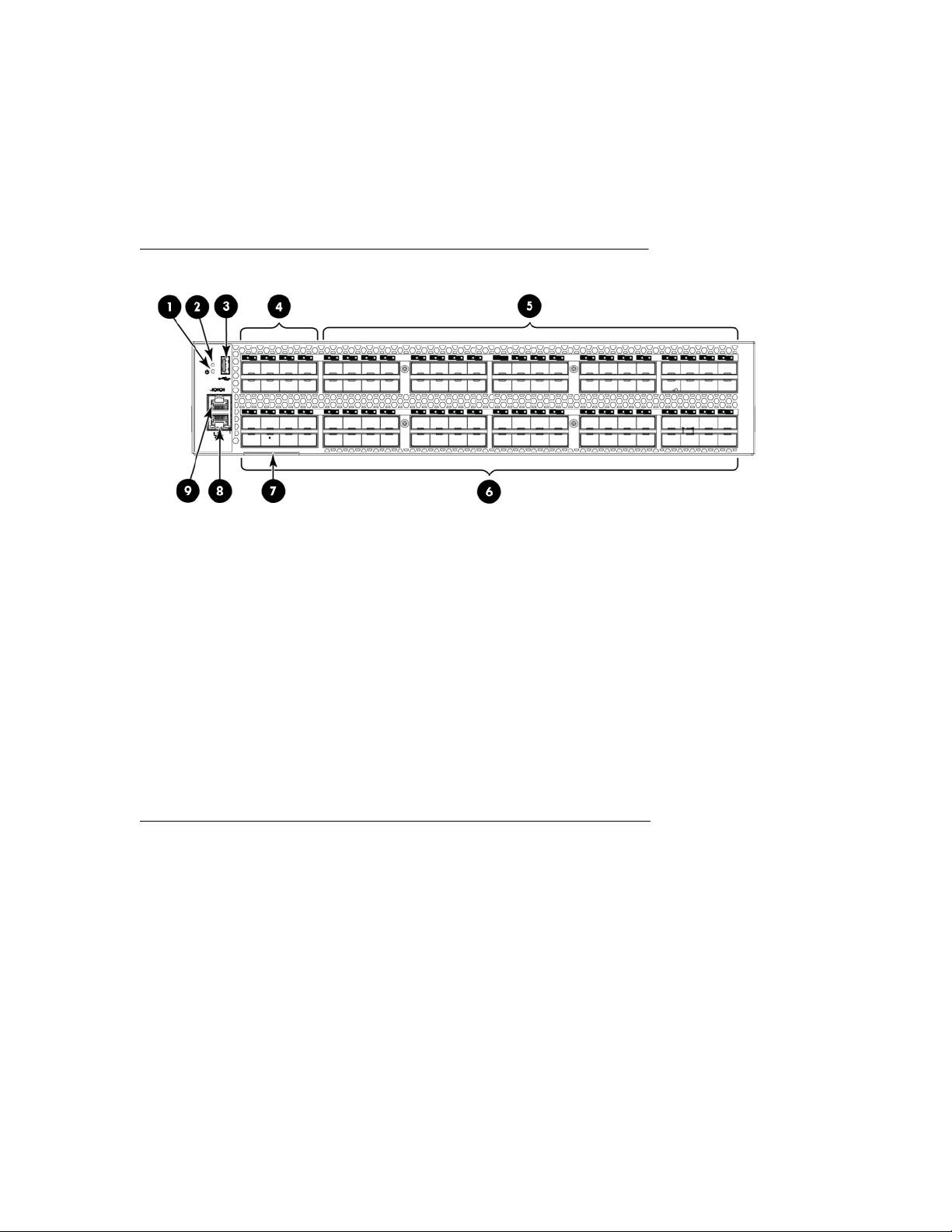
Port side of the switch
Figure 1: Port side of the HPE StoreFabric SN6500B 16Gb FC Switch on page 8 shows the port
side of the SN6500B StoreFabric 16Gb FC Switch.
1. System power LED 2. System status LED
3. USB port 4. FC ports 0–7
5. FC ports 8–47 6. FC ports 48–95
7. Switch ID pull-out tab 8. Management Ethernet port with LED
9. Serial console port
Figure 1: Port side of the HPE StoreFabric SN6500B 16Gb FC Switch
Nonport side of the switch
Figure 2: Nonport side of HPE SN6500B StoreFabric 16Gb FC Switch on page 9 shows the
nonport side of the StoreFabric SN6500B 16Gb FC Switch, which contains the power supplies (including
the AC power receptacle) and fans.
8 Port side of the switch
Page 9
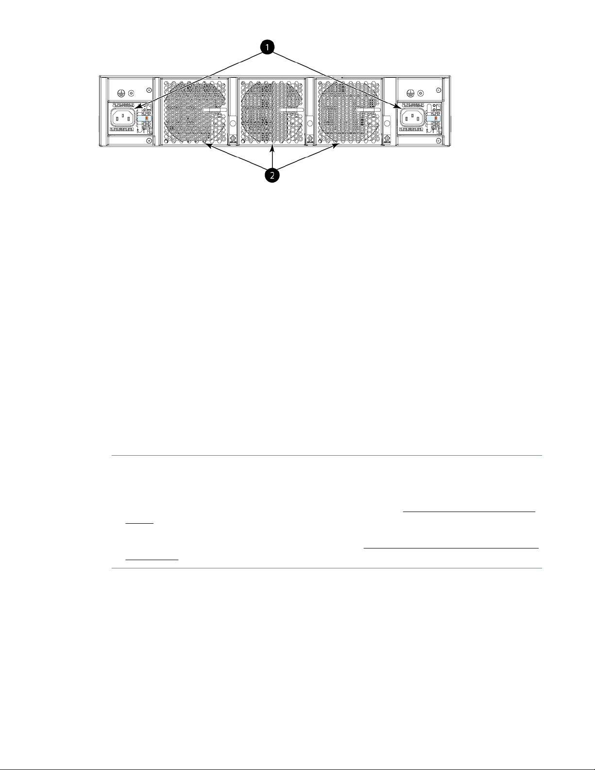
1. Power supplies with integral fans 2. Fans
Figure 2: Nonport side of HPE SN6500B StoreFabric 16Gb FC Switch
Software options
The following optional software kits and licenses are available:
• The Power Pack Software Bundle kit includes:
◦ Fabric Watch
◦ ISL Trunking
◦ Extended Fabric
◦ Advanced Performance Monitor
◦ Fabric Vision Software
• Extended Fabric
• Fabric Watch
• Advanced Performance Monitor
• ISL Trunking
• Integrated Routing
• StoreFabric SN6500B 16Gb 24-port FC Upgrade LTU
NOTE:
• Adaptive Networking and Server Application Optimization features are included by default in the
switch firmware FOS 7.2.x or later, and do not require a separate license. For more information
about supported FOS versions, see the HPE SPOCK website at http://www.hpe.com/storage/
spock.
• For the latest information on supported software components, see the product QuickSpecs
available from the Hewlett Packard Enterprise website: http://www.hpe.com/support/sn6500b/
quickspecs
ISL Trunking
HPE ISL Trunking is optional software, requiring a license, that allows you to create trunking groups of
ISLs between adjacent switches. Up to eight FC ports on the StoreFabric SN6500B 16Gb FC Switch can
be used as a trunking group to achieve speeds of up to 128 Gb/s (256 Gb/s full duplex) for optimal
bandwidth utilization and load balancing. For more information about ISL Trunking, see the Fabric OS
Administrator Guide.
Software options 9
Page 10

Hardware options
Table 1: Optional hardware kits
Hardware kit Part number
HPE PremierFlex OM4+ Fiber Optic Cables 1m PremierFlex OM4 LC/LC Multi-mode Optical Cable
2m PremierFlex OM4 LC/LC Multi-mode Optical Cable
5m PremierFlex OM4 LC/LC Multi-mode Optical Cable
15m PremierFlex OM4 LC/LC Multi-mode Optical
Cable
30m PremierFlex OM4 LC/LC Multi-mode Optical
Cable
50m PremierFlex OM4 LC/LC Multi-mode Optical
Cable
HPE PremierFlex OM4+ QSFP Fiber Optic
Cables
HPE PremierFlex MPO to 4xLC OM4 Splitter
Cables
1m (12f) PremierFlex OM4 MPO/MPO Optical Cable
2m (12f) PremierFlex OM4 MPO/MPO Optical Cable
5m (12f) PremierFlex OM4 MPO/MPO Optical Cable
10m (12f) PremierFlex OM4 MPO/MPO Optical Cable
15m (12f) PremierFlex OM4 MPO/MPO Optical Cable
30m (12f) PremierFlex OM4 MPO/MPO Optical Cable
50m (12f) PremierFlex OM4 MPO/MPO Optical Cable
100m (12f) PremierFlex OM4 MPO/MPO Optical
Cable
5m PremierFlex MPO to 4xLC Optical Cable
15m PremierFlex MPO to 4xLC Optical Cable
30m PremierFlex MPO to 4xLC Optical Cable
50m PremierFlex MPO to 4xLC Optical Cable
OM3 LC-LC Optical Cables 0.5m OM3 LC-LC Multi-mode Optical Cable
10 Hardware options
1m OM3 LC-LC Multi-mode Optical Cable
2m OM3 LC-LC Multi-mode Optical Cable
Table Continued
Page 11
Hardware kit Part number
NOTE:
For the latest information on supported hardware components, see the product QuickSpecs
available on the Hewlett Packard Enterprise website.
SFP transceivers
Table 2: SFP transceiver options
Option Part number
8Gb Transceivers HPE 8Gb Shortwave B-series FC SFP+
5m OM3 LC-LC Multi-mode Optical Cable
15m OM3 LC-LC Multi-mode Optical Cable
30m OM3 LC-LC Multi-mode Optical Cable
50m OM3 LC-LC Multi-mode Optical Cable
HPE 8Gb LW B-series 10km FC SFP+
HPE B-series 8Gb LW 25km FC SFP
10Gb Transceivers HPE B-series 10Gb SFP+ Short Range Transceiver
HPE B-series 10Gb SFP+ Long Range Transceiver
16Gb Transceivers HPE B-series 16Gb SFP+ Short Wave Transceiver
16Gb Long Wave
Transceivers
HPE 16Gb Long Wave B-series 10km FC SFP+ 1 Pack
HPE SN6000B 16Gb FC Switch
This section provides an overview of the SN6000B 16Gb FC Switch. It describes platform capabilities and
components, the physical layout of the switch, and hardware and software options.
Overview
The SN6000B 16Gb FC Switch is a 48-port autosensing 4, 8, 10, or 16 Gb/s FC switch that delivers the
latest Hewlett Packard Enterprise single-chip architecture for FC SANs. The SN6000B 16Gb FC Switch is
an enterprise-class switch designed to handle the large-scale SAN requirements of an enterprise
environment, and can also be used to address the SAN requirements of a small-sized or medium-sized
workgroup.
The SN6000B 16Gb FC Switch meets RAS, performance, and scalability requirements of an enterprise
switch, while delivering interoperability and ease-of-use advantages. This switch is the latest offering from
the Hewlett Packard Enterprise family of entry-to-enterprise products.
SFP transceivers 11
Page 12

The SN6000B 16Gb FC Switch provides 48 ports in a single (1U) height switch that enables the creation
of very dense fabrics in a relatively small space.
The SN6000B 16Gb FC Switch also offers POD licensing. Base models of the switch contain 24 ports,
and up to two additional 12-port POD licenses can be purchased. The switch provides excellent value as
the foundation of a SAN, and can grow to meet an organization’s SAN needs.
The SN6000B 16Gb FC Switch can be configured in AG mode, which enables configuring the enterprise
fabric to handle additional N_Ports instead of domains. Reducing the number of domain IDs and ports
simplifies configuration and management in a large fabric. Switches in AG mode are logically transparent
to the host and fabric. You can increase the number of hosts that have access to the fabric without
increasing the number of switches.
Platform capabilities
The SN6000B 16Gb FC Switch offers the following features and capabilities:
• Up to 48 autosensing ports of high-performance 16 Gb/s technology in a single domain.
• POD scaling from 24 to 36 or 48 ports.
• 4, 8, and 16 Gb/s autosensing FC switch and router ports.
◦ 4 and 8 Gb/s performance is enabled by 8 Gb/s SFP+ transceivers.
◦ 4, 8, and 16 Gb/s performance is enabled by 16 Gb/s SFP+ transceivers.
• 10 Gb/s manual set capability on FC ports (requires the optional 10 Gb FC-IP/FC license).
◦ 10 Gb/s performance is enabled by 10 Gb/s SFP+ transceivers.
◦ The first eight ports can be configured for 10 Gb/s for metro connectivity.
• Universal ports self-configure as E, F, M, or D ports. EX_Ports can be activated on a per port basis
with the optional Integrated Routing license. The D_Port feature provides physical media diagnostic,
troubleshooting, and verification services.
• In-flight data compression and encryption on up to two ports provides efficient link utilization and
security.
• VF support improves isolation between VFs.
• FCR service, available with the optional Integrated Routing license, provides improved scalability and
fault isolation.
• FICON, FICON Cascading, and FICON CUP ready.
• ISL Trunking (licensable), which allows up to eight ports (at 4, 8, or 16 Gb/s) between a pair of
switches combined to form a single, logical ISL with a speed of up to 128 Gb/s (256 Gb/s full duplex)
for optimal bandwidth utilization and load balancing.
• DPS, which optimizes fabric-wide performance and load balancing by automatically routing data to the
most efficient available path in the fabric.
• Hewlett Packard Enterprise-branded SFP+ optical transceivers that support any combination of SWL,
LWL and ELWL optical media among the switch ports.
• Support for unicast, multicast (255 groups), and broadcast data traffic types.
• Fabric OS delivers distributed intelligence throughout the network, and enables a wide range of valueadded applications such as Advanced Web Tools and Zoning. Optional Fabric Services include
Adaptive Networking with QoS, Extended Fabrics, Enhanced Group Management, Fabric Watch, ISL
Trunking, and APM.
• Support for AG configuration where server ports connected to the fabric core are virtualized.
• Hardware zoning is accomplished at the port level of the switch and by WWN. Hardware zoning
permits or denies delivery of frames to any destination port address.
• Extensive diagnostics and system-monitoring capabilities for enhanced RAS.
• 10 Gb/s FC integration on the same port provides DWDM metro connectivity on the same switch (can
be done on the first eight ports only).
• Real-time power monitoring enables monitoring the fabric power usage at a switch level.
• Port-to-port latency minimized to 800 nanoseconds through cut-through frame routing at 16 Gb/s.
12 Platform capabilities
Page 13
Platform components
• A system motherboard that features a PowerPC 440EPx RISC CPU running at 667 MHz, with
integrated peripherals, and provides high performance with low power consumption
• An RJ-45 10/100 Base-T Ethernet system management port that supports switch IP address discovery
and configuration
• One RS-232 serial port with an RJ-45 connector for initial switch setup and factory default restoration,
(the integral LEDs remain unlit at all times)
• A USB port that provides storage for firmware updates, supportsave command output, and storage
for configuration uploads and downloads
• Two hot-swappable, redundant power supply and fan assemblies. There are two fans per power
supply
• Designed for rack mounting in a 19-inch EIA rack (1U high)
• One LED (green/amber) per FC port to indicate status
• One LED (green) for system power
• One LED (green/amber) for system status
• Two Ethernet LEDs (integrated with RJ-45) for speed and activity status
• SEEPROM for switch identification
• Voltage and temperature monitoring
• RTC with battery
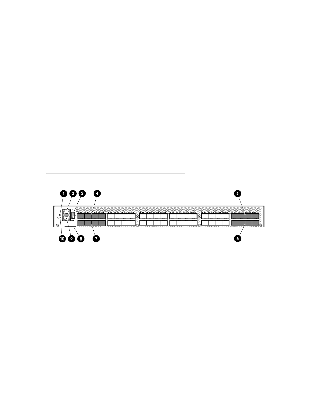
Port side of the switch
Figure 3: Port side of the HPE SN6000B 16Gb FC Switch on page 13 shows the port side of the
SN6000B 16Gb FC Switch.
1. System status LED 2. Management Ethernet port with LEDs
3. USB port 4. FC ports (0-3)
5. FC ports (40-43) 6. FC ports (44-47)
7. FC ports (4-7) 8. Switch ID pull-out tab
9. Serial console port 10. System power LED
Figure 3: Port side of the HPE SN6000B 16Gb FC Switch
NOTE:
The two LEDs on the serial console port are nonfunctional.
Platform components 13
Page 14
Nonport side of the switch
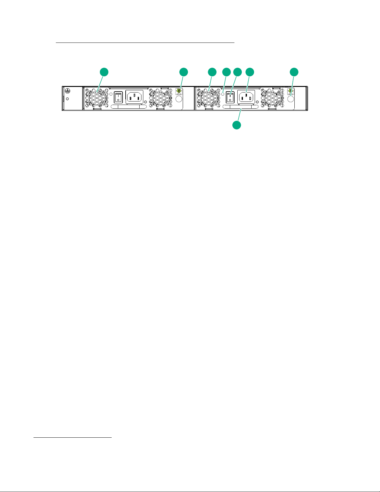
1 2 3 4 5 6 7
8
Figure 4: Nonport side of the HPE SN6000B 16Gb FC Switch on page 14 shows the nonport side of
the SN6000B 16Gb FC Switch, which contains two power supply and fan assemblies (each including an
AC power receptacle and AC power switch).
1. Power supply and fan assembly #2 2. Airflow label
3. Power supply and fan assembly #1 4. Power supply and fan assembly LED
5. On/off switch 6. Power plug receptacle
7. Thumbscrew 8. Handle
Figure 4: Nonport side of the HPE SN6000B 16Gb FC Switch
Software options
The following optional software kits and licenses are available:
• The Power Pack Software Bundle kit includes:
◦ Adaptive Networking
◦ Fabric Watch
◦ ISL Trunking
◦ Extended Fabric
◦ Server Application Optimization
◦ Advanced Performance Monitor
◦ Fabric Vision Software
• Extended Fabric
• Fabric Watch
• Advanced Performance Monitor
• ISL Trunking
• Integrated Routing
• HPE SN6000B 10Gb Integrated FC Extension (enables 10Gb FC for first eight ports)
• SN6000B 16Gb 24-48 12-port FC Upgrade LTU
1
1
Fabric OS 7.2.0a or later
14 Nonport side of the switch
Page 15
NOTE:
• Adaptive Networking and Server Application Optimization features are included by default in the
• For the latest information on supported software components, see the product QuickSpecs
ISL Trunking
ISL Trunking is optional software that enables creating trunking groups of ISLs between adjacent
switches. Up to eight FC ports on the SN6000B 16Gb FC Switch can be used as a trunking group to
achieve speeds of up to 128 Gb/s (256 Gb/s full duplex) for optimal bandwidth utilization and load
balancing.
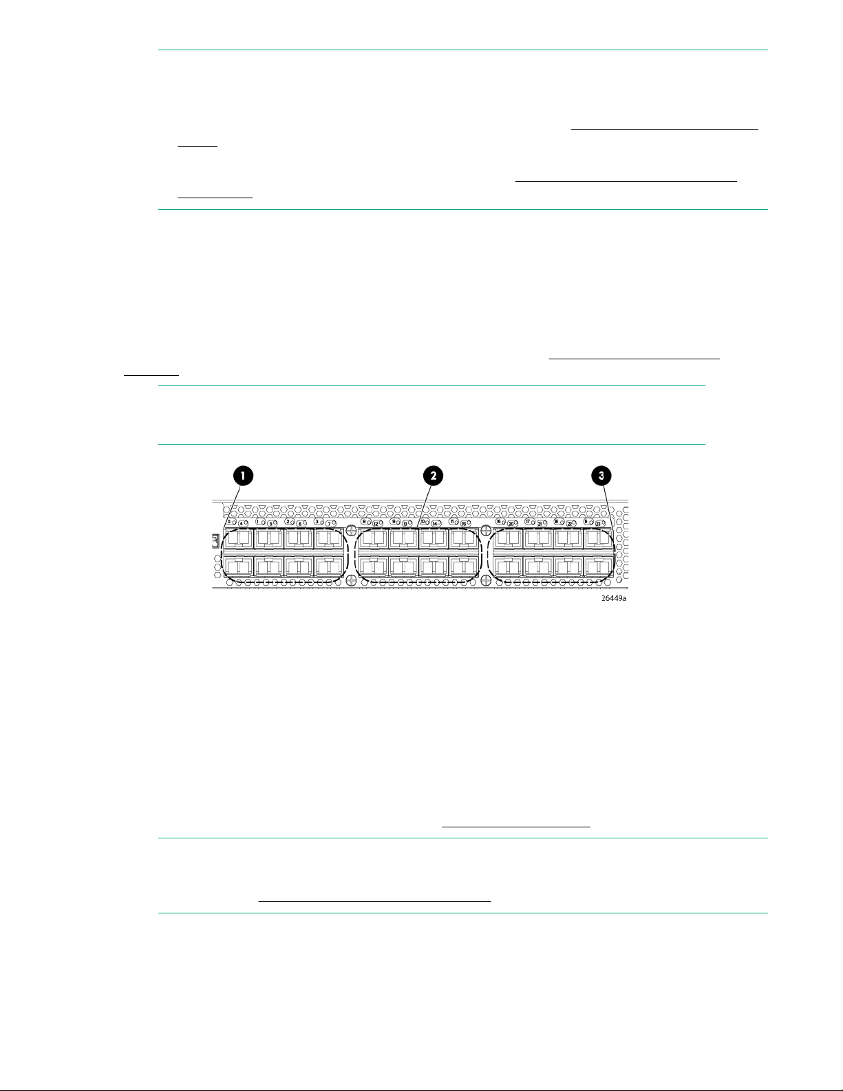
For example, the FC ports on the SAN Switch are numbered from left to right and color-coded in groups
of eight to indicate which ports you can combine into trunking groups.
example on page 15 shows the switch with three trunking groups of eight ports.
NOTE:
If your switch is licensed for ISL Trunking, use the trunking groups available on the switch.
switch firmware FOS 7.2.x or later, and do not require a separate license. For more information
about supported FOS versions, see the HPE SPOCK website at http://www.hpe.com/storage/
spock.
available from the Hewlett Packard Enterprise website: http://www.hpe.com/info/sn6000b/
quickspecs.
Figure 5: Trunking groups
Figure 5: Trunking groups example
1. Trunking group 1: Ports 0–7 2. Trunking group 2: Ports 8–15
3. Trunking group 3: Ports 16–23
For more information about ISL Trunking, see the Fabric OS 7.0.x Administrator's Guide for the firmware
version you are running.
Hardware options
For more information on optional hardware kits, see Optional hardware kits.
NOTE:
For the latest information on supported hardware components, see the product QuickSpecs
available on the Hewlett Packard Enterprise website.
ISL Trunking 15
Page 16

SFP transceivers
Table 3: SFP transceiver options
Option Part number
8Gb Transceivers 8Gb Shortwave B-series FC SFP+
10Gb Transceivers B-series 10Gb SFP+ Short Range Transceiver
16Gb Transceivers B-series 16Gb SFP+ Short Wave Transceiver
8Gb LW B-series 10km FC SFP+
B-series 8Gb LW 25km FC SFP
B-series 10Gb SFP+ Long Range Transceiver
16Gb Long Wave
Transceivers
16Gb Long Wave B-series 10km FC SFP+ 1 Pack
HPE SN3000B 16Gb FC Switch
This section provides an overview of the SN3000B 16Gb FC Switch. It describes platform capabilities and
components, the physical layout of the switch, and hardware and software options.
Overview
The SN3000B 16Gb FC Switch is a 24-port autosensing 4, 8, or 16 Gb/s FC switch that delivers the latest
Hewlett Packard Enterprise single-chip architecture for FC SANs. The SN3000B 16Gb FC Switch is a
small-sized to mid-sized business-class switch that is designed to handle smaller-scale SAN
requirements.
The SN3000B 16Gb FC Switch provides up to 24 ports in a single height (1U) switch, which enables the
creation of very dense fabrics in a relatively small space. This switch also offers POD licensing. Base
models of the switch contain 12 ports, and an additional 12-port POD license can be purchased.
NOTE:
The base model of the SN3000B 16Gb FC Switch includes a single power supply and fan module
assembly. An optional second power supply and fan module assembly can be added to the switch
as an upgrade, for redundancy and hot-swap capability.
The SN3000B 16Gb FC Switch supplies RAS performance and the scalability requirements of an
enterprise switch along with interoperability and ease-of-use advantages.
The SN3000B 16Gb FC Switch can be configured in AG mode, which enables configuring the enterprise
fabric to handle additional N_Ports instead of domains. Reducing the number of domain IDs and ports
simplifies configuration and management in a large fabric. Switches in AG mode are logically transparent
to the host and the fabric. You can increase the number of hosts that have access to the fabric without
increasing the number of switches.
Platform capabilities
The SN3000B 16Gb FC Switch offers the following features and capabilities:
16 SFP transceivers
Page 17

• Up to 24 autosensing ports of high-performance 16-Gb/s technology in a single domain.
• POD scaling from 12 to 24 ports.
• 4, 8, and 16 Gb/s autosensing FC switch and router ports
◦ 4 and 8 Gb/s performance is enabled by 8 Gb/s SFP+ transceivers
◦ 4, 8, and 16 Gb/s performance is enabled by 16 Gb/s SFP+ transceivers
• Universal ports self-configure as E, F, or M ports. EX_Ports can be activated on a per-port basis with
the optional Integrated Routing license. D-port functionality is also available for diagnostics.
• Airflow is set for port-side exhaust.
• ISL Trunking (licensable), which allows up to eight ports (at 4, 8, or 16 Gb/s speeds) between a pair of
switches combined to form a single, logical ISL with a speed of up to 128 Gb/s (256 Gb/s full duplex)
for optimal bandwidth utilization and load balancing. The base model permits one eight-port trunk plus
one four-port trunk.
• DPS, which optimizes fabric-wide performance and load balancing by automatically routing data to the
most efficient available path in the fabric.
• Hewlett Packard Enterprise-branded SFP+ optical transceivers that support any combination of SWL,
LWL, and ELWL optical media among the switch ports.
• Support for unicast traffic type.
• Fabric OS delivers distributed intelligence throughout the network, and enables a wide range of valueadded applications such as Advanced Web Tools and Zoning. Optional Fabric Services include
Adaptive Networking with QoS, Extended Fabrics, Enhanced Group Management, Fabric Watch, ISL
Trunking, and APM.
• Support for AG configuration where server ports connected to the fabric core will be virtualized.
• Hardware zoning is accomplished at the port level of the switch and by WWN. Hardware zoning
permits or denies delivery of frames to any destination port address.
• Extensive diagnostics and system-monitoring capabilities for enhanced RAS.
• Real-time power monitoring enables users to monitor real-time power usage of the fabric at a switch
level.
• Port-to-port latency minimized to 800 ns using cut-through frame routing at 16 Gb/s.
Platform components
• A system motherboard that features a PowerPC 440EPx RISC CPU running at 667 MHz, with
integrated peripherals
• An RJ-45 10/100 Base-T Ethernet system management port that supports switch IP address discovery
and configuration
• One RS-232 serial port with an RJ-45 connector for initial switch setup and factory default restoration
(the integral LEDs remain unlit at all times)
• A USB port that provides storage for firmware updates, supportsave command output, and storage
for configuration uploads and downloads
• One power supply and fan assembly in the base model. There are two fans per assembly. An optional
second power supply and fan assembly is available for redundancy and hot-swap capability
• One LED (green/amber) per FC port to indicate status
• One LED (green) for system power
• One LED (green/amber) for system status
• Two Ethernet port LEDs (integrated with RJ45) for speed and port activity. (A green LED for port
speed and an amber LED for port activity)
• SEEPROM for switch identification
• Voltage, fan, and temperature monitors
• RTC with battery
Platform components 17
Page 18
Port side of the switch
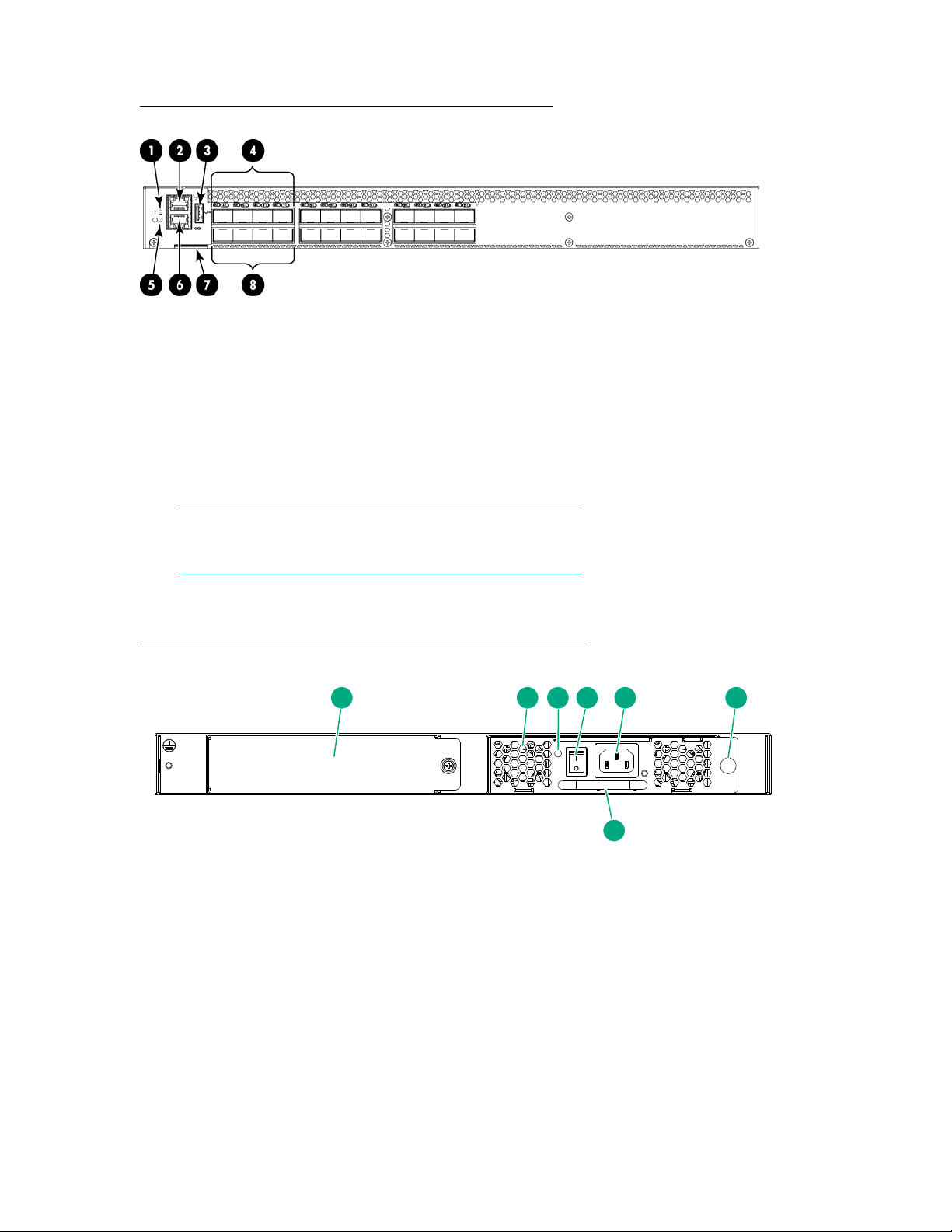
1 2 3 4 5 6
7
Figure 6: Port side of the HPE SN3000B 16Gb FC Switch on page 18 shows the port side of the
SN3000B 16Gb FC Switch.
Figure 6: Port side of the HPE SN3000B 16Gb FC Switch
1. System status LED 2. Management Ethernet port with LEDs
3. USB port 4. FC ports (0-3)
5. System power LED 6. Serial console port
7. Switch ID pull-out tab 8. FC ports (4–7)
NOTE:
The two LEDs on the serial console port are nonfunctional.
Nonport side of the switch
Figure 7: Nonport side of the HPE SN3000B 16Gb FC Switch on page 18 shows the nonport side of
the SN3000B 16Gb Switch.
Figure 7: Nonport side of the HPE SN3000B 16Gb FC Switch
1. Filler panel (Optional Power supply and fan
assembly can be added in this slot)
3. Power supply and fan assembly LED 4. On/off switch
2. Power supply and fan assembly #1
5. Power plug receptacle 6. Thumbscrew
7. Handle
18 Port side of the switch
Page 19

Software options
The following optional software kits and licenses are available.
• The Power Pack+ Software Bundle kit includes:
◦ Adaptive Networking
◦ Fabric Watch
◦ ISL Trunking
◦ Extended Fabric
◦ Server Application Optimization
◦ Advanced Performance Monitor
◦ Fabric Vision Software
• HPE B-series 8-24 Port SAN Switch Adaptive Networking LTU
• HPE B-series 8-24 Port SAN Switch ISL Trunking LTU
• HPE SN3000B 16Gb 24/12 FC Switch 12-port Upgrade LTU
NOTE:
• Adaptive Networking and Server Application Optimization features are included by default in the
switch firmware FOS 7.2.x or later, and do not require a separate license. For more information
about supported FOS versions, see the SPOCK website at http://www.hpe.com/storage/
spock.
• For the latest information on supported software components, see the product QuickSpecs
available from the Hewlett Packard Enterprise website: http://www.hpe.com/info/sn3000b/
quickspecs
ISL Trunking
ISL Trunking is optional software that enables creating trunking groups of ISLs between adjacent
switches. Up to eight FC ports on the SN3000B 16Gb FC Switch can be used as a trunking group to
achieve speeds of up to 128 Gb/s (256 Gb/s full duplex) for optimal bandwidth utilization and load
balancing.
For example, the FC ports on the SAN Switch are numbered from left to right and color-coded in groups
of eight to indicate which ports you can combine into trunking groups. Figure 8: HPE SN3000B 16Gb FC
Switch trunking groups example on page 20 shows the switch with three trunking groups of eight
ports.
NOTE:
If your switch is licensed for ISL Trunking, use the trunking groups available on the switch.
Software options 19
Page 20
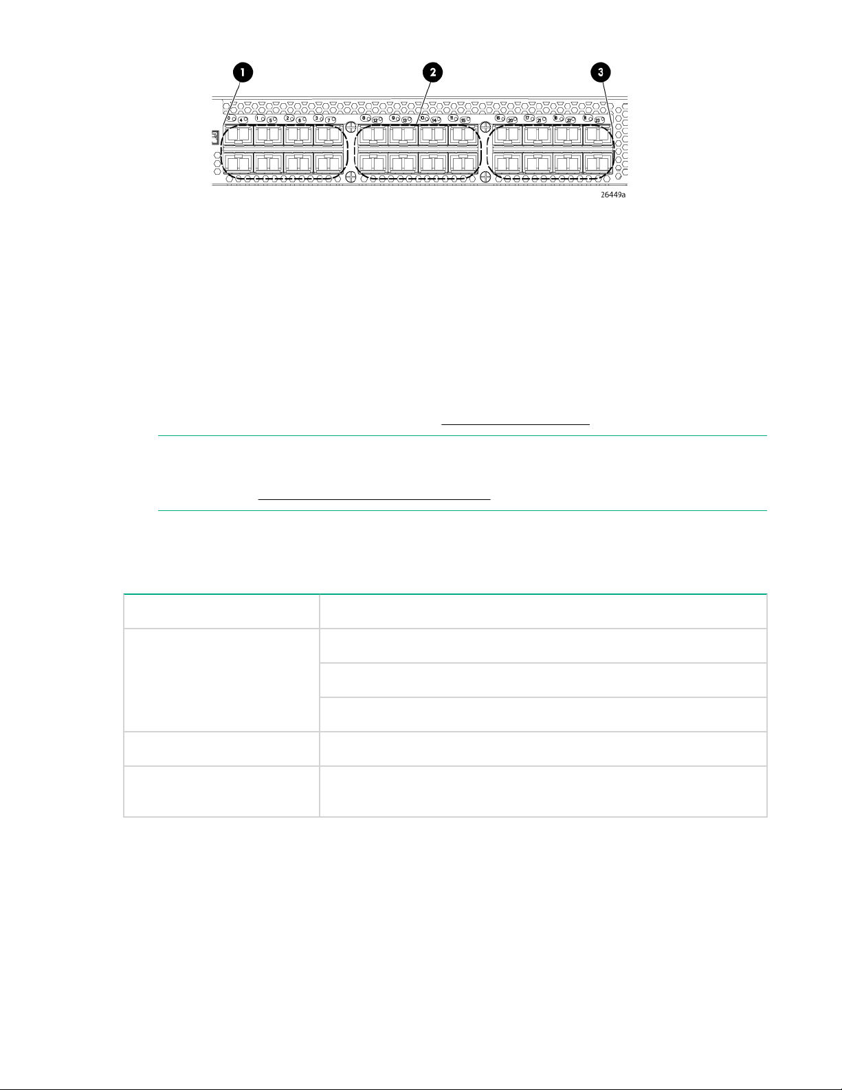
1. Trunking group 1: Ports 0–7 2. Trunking group 2: Ports 8–15
3. Trunking group 3: Ports 16–23
Figure 8: HPE SN3000B 16Gb FC Switch trunking groups example
For more information about ISL Trunking, see the Fabric OS 7.0.x Administrator's Guide for the firmware
version you are running.
Hardware options
For more information on optional hardware kits, see Optional hardware kits.
NOTE:
For the latest information on supported hardware components, see the product QuickSpecs
available on the Hewlett Packard Enterprise website.
SFP transceivers
Table 4: SFP transceiver options
Option Part number
8 Gb Transceivers 8Gb Shortwave B-series FC SFP+
8Gb LW B-series 10km FC SFP+
B-series 8Gb LW 25km FC SFP
16 Gb Transceivers B-series 16Gb SFP+ Short Wave Transceiver
16 Gb Long Wave
Transceivers
16Gb Long Wave B-series 10km FC SFP+ 1 Pack
HPE StoreFabric SN4000B SAN Extension Switch
This section provides an overview of the StoreFabric SN4000B SAN Extension Switch. It describes
platform capabilities and components, and the physical layout of the switch.
Overview
The StoreFabric SN4000B SAN Extension Switch is a platform for FCIP that enables transmission of
Fiber Channel data over long distances through IP networks by wrapping Fiber Channel frames in IP
20 Hardware options
Page 21

packets. Each end of the FCIP communication path is a compatible FCIP device. The switch operates
independently or in a fabric containing multiple extension switches.
Platform capabilities
The SN4000B SAN Extension Switch offers the following features and capabilities:
• Multiple logical FCIP tunnels with a maximum tunnel bandwidth up to 20 Gb/s allows for scalable
connectivity between sites.
• The FCIP trunking feature allows multiple IP source and destination address pairs (defined as FCIP
circuits) providing high bandwidth FCIP tunnel and lossless failover resiliency using multiple 1/10GbE
or 40GbE interfaces. Additionally, each FCIP circuit supports four QoS classes (Class F, High,
Medium, and Low Priority), each as a TCP connection.
• The ARL feature meets minimum bandwidth guarantee for each tunnel while fully utilizing the available
network bandwidth, without any adverse throughput performance during high traffic load.
• Hardware-based compression maximizes throughput over lower bandwidth links in a WAN, thereby
optimizing the cost efficiencies of FCIP. The switch compresses the FC frames before they are
encapsulated into FCIP packets.
• Key protocol features are enabled in the FCIP implementation to optimize performance of extension
over IP networks.
• The hardware-based IPSec supports a mix of secure and nonsecure tunnels on the same Ethernet
port, jumbo frames, and VLAN-tagged connections. The IPSec function of the switch supports both
IPv4 and IPv6.
• FastWrite, Open Systems Tape Pipelining, and Advanced Accelerator for FICON mitigate the latency
effect of a long distance FCIP connection over IP WAN.
• FCIP HCL provides in-service firmware upgrade for supporting business operations 24/7.
• Built-in WAN link tester generates traffic over an IP connection to test for maximum throughput,
congestion, loss percentage, out-of-order delivery, latency, and other network conditions. It helps
determine the health of a WAN link before deploying it for use.
• Fabric Vision advanced monitoring provides the following functions:
◦ Policy-based monitoring monitors FCIP connectivity and WAN anomalies using multilayer metrics.
◦ Flow monitoring reports IOPS and data rate of individual I/O flows of inter-DC replication and tape
backup operations.
◦ Flow generator generates FC frames for a defined flow with default or custom size and pattern and
sends them across FCIP tunnel to help validate end-to-end network setup and configuration.
• Fabric OS delivers distributed intelligence throughout the network, and enables a wide range of valueadded applications.
Platform components
• A total of 24 Fibre Channel ports with link speeds of 2, 4, 8, and 16 Gb/s, compatible with SWL, LWL,
and ELWL SFP+ transceivers
• Rack-mountable 2U chassis
• A total of 16 1GbE/10GbE ports, compatible with copper, ultra short reach, short reach, and long reach
SFP/SFP+ transceivers
• Two 40 GbE ports compatible with short reach and long reach QSFP transceivers
• An RJ-45 Ethernet management port with 10/100/1000 Mb/s autonegotiating capability
• A USB port that provides storage for firmware updates, supportSave command output, and storage
for configuration uploads and downloads
• Two redundant, hot-swappable 1100 W AC/DC power supply units with integral fans
• Three port-side exhaust DC fan FRUs
Platform capabilities 21
Page 22
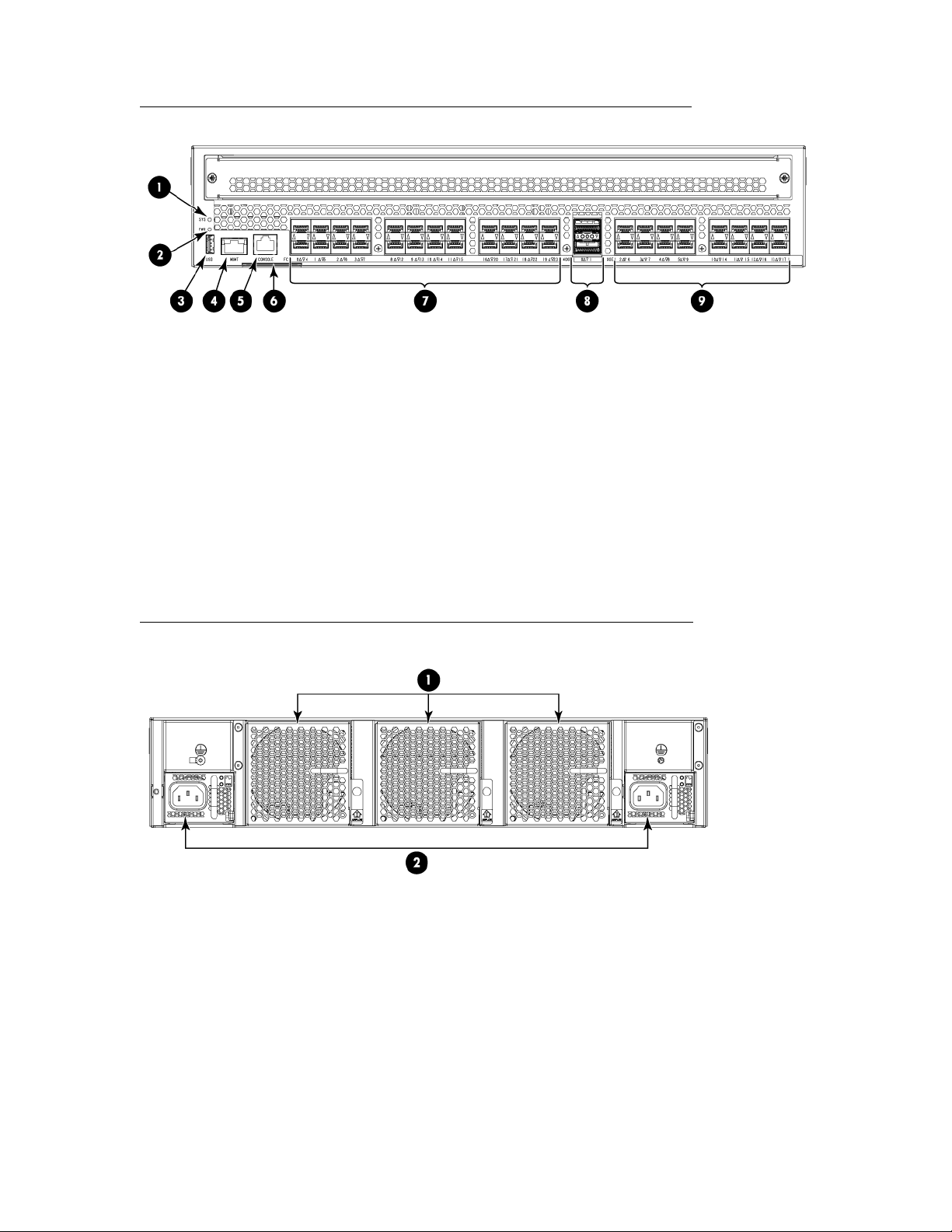
Port side of the switch
Figure 9: Port side of the HPE StoreFabric SN4000B SAN Extension Switch on page 22 shows the
port side of the StoreFabric SN4000B SAN Extension Switch.
Figure 9: Port side of the HPE StoreFabric SN4000B SAN Extension Switch
1. System status LED 2. Power Status LED
3. USB port 4. Ethernet management Port
5. Console port (RJ-45) 6. Switch ID pull-out tab
7. 16 GbE FC ports (24) 8. 40 GbE FCIP ports (QSFP) (2)
9. 1/10 GbE FCIP ports (16)
Nonport side of the switch
Figure 10: Nonport side of the StoreFabric SN4000B SAN Extension Switch on page 22 shows the
nonport side of the StoreFabric SN4000B SAN Extension Switch.
Figure 10: Nonport side of the StoreFabric SN4000B SAN Extension Switch
1. Fan FRUs 2. Power supply FRUs with integral fans
Software options
The following optional software kits and licenses are available:
• HPE StoreFabric SN4000B 10Gb WAN Rate Upgrade LTU
• HPE StoreFabric SN4000B 40Gb WAN Rate Upgrade LTU
• HPE StoreFabric SN4000B FICON Accelerator LTU
22 Port side of the switch
Page 23

NOTE:
For the latest information on supported software components, see the product QuickSpecs available
from the Hewlett Packard Enterprise website: http://www.hpe.com/info/sn4000b/quickspecs.
Hardware options
For more information on optional hardware kits, see Optional hardware kits.
NOTE:
For the latest information on supported hardware components, see the product QuickSpecs
available on the Hewlett Packard Enterprise website.
Transceivers
Table 5: Transceiver options
Option Part number
8 Gb Transceivers 8Gb Shortwave B-series FC SFP+ 1 Pack
8Gb LW B-series 10km FC SFP+ 1 Pack
B-series 8Gb LW 25km FC SFP 1 Pack
16 Gb Transceivers B-series 16Gb SFP+ Short Wave Transceiver
16 Gb Long Wave
Transceivers
1 GbE Transceivers B-series 1GbE LX SFP Transceiver
10 GbE Transceivers 10GbE SW B-series SFP+ Transceiver
40 GbE Transceivers B-series 40GbE LR QSFP+ Transceiver
B-series 16Gb SFP+ LW 10km XCVR
B-series 16Gb LW 25km FC SFP 1Pk XCVR
B-series 1Gb Ethernet Copper SFP Transceiver
10GbE LW B-series SFP+ Transceiver
B-series 40GbE SR QSFP+ Transceiver
Hardware options 23
Page 24

Installing and configuring HPE 16Gb FC switches
This chapter provides installation and configuration information for the HPE 16Gb FC switches.
Accessories
The following items are included with the standard shipment of a fully-configured 16Gb FC Switch. When
opening the packages, verify that the following items are included and that no damage has occurred
during shipping:
• One StoreFabric SN6500B 16Gb FC Switch with two hot-swappable power supplies and three hotswappable fans, or one SN6000B 16Gb FC Switch with two integrated power supply and fan
assemblies, or one SN3000B 16Gb FC Switch with one integrated Power supply and fan assembly, or
one StoreFabric SN4000B SAN Extension Switch with two integrated power supplies and integral
fans.
NOTE:
The SN3000B 16Gb FC Switch can, as an option, be configured with a second Power supply
and fan assembly, which must be ordered separately.
• Serial cable with an RJ-45 connector plus an adaptor for RJ-45 to DB9.
• Power cords: two included with the StoreFabric SN4000B, SN6500B, and SN6000B switches, one
included with the SN3000B.
• Rubber feet, required to set up the switch as a standalone unit.
• One accessory kit with the following items:
◦ Rack Mount Kit, including rails, rail mounting hardware, and plenum.
◦ Hewlett Packard Enterprise product documentation, including Read Me First, Safety Guides, User
License, and Warranty.
• HPE EZ Switch and China ROHS documentation.
• HP SAN Network Advisor DVD.
Installation and safety considerations
You can install the switch in a rack or as a standalone device on a flat surface. Hewlett Packard
Enterprise recommends mounting the SN6000B 16Gb FC Switch, the SN3000B 16Gb FC Switch, and the
StoreFabric SN4000B SAN Extension Switch in any of the supported HPE racks.
The supported HPE racks include the HPE 10000 G2 Series, the Intelligent Series racks, and the HPE
11000 G2 Series racks.
Electrical considerations
For successful installation and operation of the switch, ensure that the following electrical requirements
are met:
• The primary outlet is wired correctly, protected by a circuit breaker, and grounded in accordance with
local electrical codes.
• The supply circuit, line fusing, and wire size are adequate, as specified by the electrical rating on the
switch nameplate.
• A maximum of 71.36 cubic meters/hour (42 cubic feet/minute). Nominal airflow is 59.47 cubic meters/
hour (35 cubic feet/minute).
• The primary AC input follows:
24 Installing and configuring HPE 16Gb FC switches
Page 25

◦ SN6000B 16Gb FC Switch and SN3000B 16Gb FC Switch
85–264 VAC Nominal: 100–240 VAC, 2.0 A; 47–63 Hz. The switch autosenses input voltage.
◦ StoreFabric SN6500B 16Gb FC Switch
90–264 VAC, Nominal: 100–240 VAC, 12.0 A–5.0 A; 47–63 Hz. The switch autosenses input
voltage.
◦ StoreFabric SN4000B SAN Extension Switch
100-240 VAC, 50-60 Hz. The switch autosenses input voltage.
Environmental considerations
For successful installation and operation of the switch, ensure that the following environmental
requirements are met:
IMPORTANT:
Always use the plenum when installing the switch in a rack.
• At a minimum, adequate cooling requires installing the switch with the intake side, the nonport side of
the switch, facing the cool-air aisle.
NOTE:
For switches with Port Side Air Intake, install the switch with the port side facing the cool-air
aisle.
• All equipment in the rack should force air in the same direction to avoid intake of exhaust air.
• A maximum of 102 cubic meters/hour (60 cubic feet/minute) and a minimum of 74.8 cubic meters/hour
(44 cubic feet/minute) of airflow must be available for air intake.
• The ambient air temperature must not exceed 40°C (104°F) while the switch is operating.
Cabling considerations
You can organize and manage cables in a number of ways, such as using cable channels on the sides of
the cabinet or patch panels.
Before installing the switch, consider the following Hewlett Packard Enterprise cabling recommendations:
• Hewlett Packard Enterprise recommends using Hewlett Packard Enterprise PremierFlex cables
because they have a minimum bend radius of 2 mm (0.08 inch) compared to previous cables, which
required a minimum 5 cm (2 inches) bend radius for a 50-micron cable under full tensile load and 3 cm
(1.2 inches) with no tensile load.
• Leave at least 1 m (3.28 ft) of slack for each port cable. This provides room to remove and replace the
switch, allows for inadvertent movement of the rack, and helps prevent the cables from being bent to
less than the minimum bend radius.
• If you are using ISL Trunking, consider grouping cables by trunking groups. The cables used in
trunking groups must meet specific requirements, as described in the Fabric OS Administrator's Guide.
• For easier maintenance, label the fiber optic cables and record the devices to which they are
connected.
• Keep LEDs visible by routing port cables and other cables away from the LEDs.
• Use Velcro straps to secure and organize fiber optic cables.
CAUTION:
Do not use tie wraps on fiber optic cables. The wraps are easily overtightened and can damage
the optical fibers.
Environmental considerations 25
Page 26

Installing the switch
This section provides instructions for installing the StoreFabric SN6500B 16Gb FC Switch, SN6000B
16Gb FC Switch, SN3000B 16Gb FC Switch, and the StoreFabric SN4000B SAN Extension Switch.
Items required for installation
To set up the switch for the first time, you will need the following:
• Workstation with an installed terminal emulator (such as HyperTerminal)
• Unused IP address and corresponding subnet mask and gateway address
• Serial cable (supplied with the switch)
• Ethernet cable
• Access to an FTP server, SCP server, or USB device for backing up the switch configuration (optional)
• HPE B-series SFP+ transceivers and compatible cables, as required (B-series 16 Gb/s SFP+
transceivers are required for 16 Gb/s performance)
IMPORTANT:
Order transceivers and cables separately. The StoreFabric SN6500B, SN6000B, SN3000B 16Gb
FC switches, and the StoreFabric SN4000B SAN Extension switches support only transceivers and
cables labeled B-series SFP+ or B-series cable. For more information on supported transceivers,
see SFP transceiver options and the HPE SAN Compatibility Tool at http://www.hpe.com/
support/SANcompatibility.
Installing the HPE StoreFabric SN6500B 16Gb FC Switch in a rack using the Rack Mount Kit
Use the SAN Switch Rack Mount Kit to install your Hewlett Packard Enterprise device in the Hewlett
Packard Enterprise custom racks:
• 10000 Series Rack
For optimal cable management, Hewlett Packard Enterprise recommends that you install the SAN Switch
Rack Mount Kit to allow the nonport side of the switch to slide out of the cool-air side of the rack. In this
installation, the port-side of the switch is set back from the edge of the rack, allowing a more gradual bend
in the fiber optic cables.
NOTE:
For the switches with Port Side Air Intake, install the Rack Mount Kit so that when the switch is
installed, the port side faces the front of the rack.
The following items are required to install the switch in a rack:
• Power cables
• #2 Phillips screwdriver
• 7/16-inch wrench or socket
• SAN Switch Rack Mount Kit hardware
SAN Switch Rack Mount Kit hardware identifies the rails and rail-mounting hardware.
26 Installing the switch
Page 27
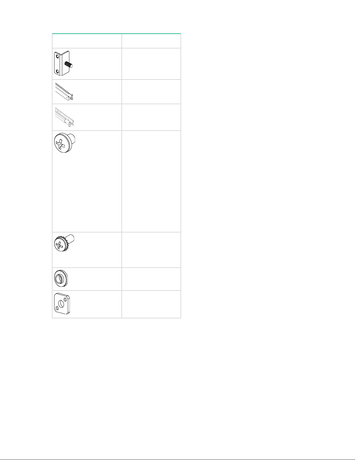
Table 6: SAN Switch Rack Mount Kit hardware
Item Description
Two rear mounting
brackets
A right inner rail and
a right outer rail
A left inner rail and a
left outer rail
Fourteen #8-32 x
5/16-inch Phillips
panhead SEMS
screws for use with
the StoreFabric
SN6500B 16Gb FC
Switch. This switch
requires 10 screws.
Fourteen #8-32 x
3/16-inch Phillips
panhead screws with
thread lock (do not
use)
Ten #10-32 x 1/2inch Phillips panhead
screws with captive
star lock washers
Eight #10 alignment
washers
Eight #10 adapter
washers
Table Continued
Installing and configuring HPE 16Gb FC switches 27
Page 28
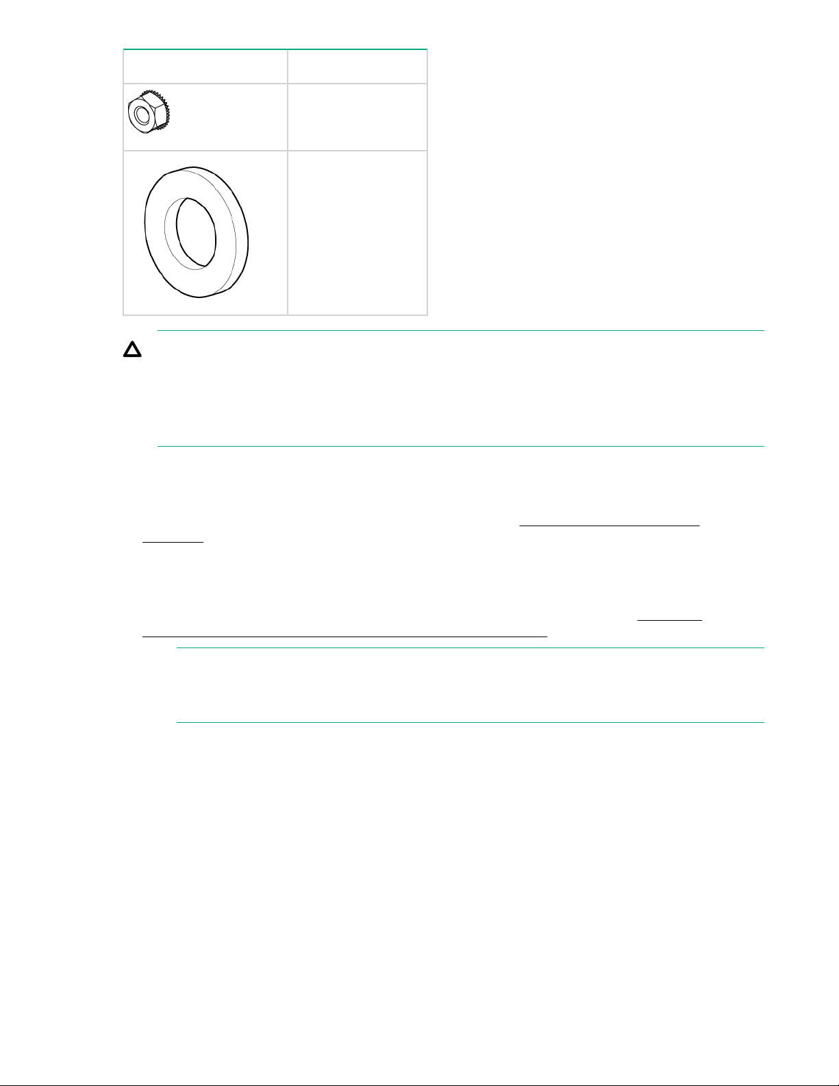
Item Description
Two 1/4-20 hex nuts
with captive star lock
washers
Two 1/4-inch flat
washers
CAUTION:
For proper airflow, the SFP+ media side of the switch port-side must face the rear of the rack. This
allows cool air to enter the front of the rack and exit from the rear.
For switches with Port Side Air Intake, the SFP+ media side of the switch port side must face the
front of the rack.
To install the switch in a rack:
Procedure
1. Verify that the required parts and hardware are available. See SAN Switch Rack Mount Kit
2. Choose a mounting location for the switch in the rack.
3. Attach the rear mounting brackets to the rear rack uprights.
hardware.
For a 10000 Series Rack, assemble each of the brackets using two #10-32 x 1/2-inch Phillips panhead
screws with captive star lock washers and two #10 adapter washers, as shown in Figure 11:
Installing the rear mounting brackets (HPE 10000 Series Rack) on page 29.
NOTE:
For switches with Port Side Air Intake, attach the rear mounting brackets to the front rack
uprights.
28 Installing and configuring HPE 16Gb FC switches
Page 29
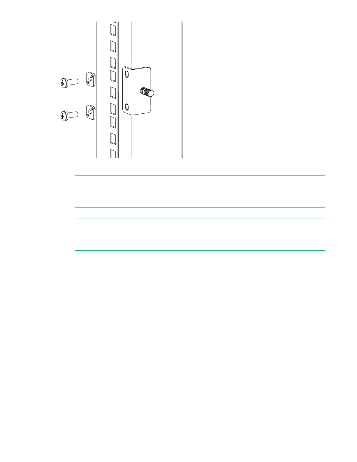
Figure 11: Installing the rear mounting brackets (HPE 10000 Series Rack)
NOTE:
The SAN Switch Rack Mount Kit contains rails labeled Left and Right to designate the left side
and right side of the switch or cabinet, as viewed from the front of the cabinet.
4. Assemble the outer rails as follows:
NOTE:
For switches with Port Side Air Intake, attach Left outer rail to the right side of the rack and Right
outer rail to the left side of the rack.
a. For switches with Port Side Air Intake, attach the left outer rail and right outer rail to the rear
mounting brackets using two 1/4-20 hex with captive star lock washers attached loosely, as shown
in Figure 12: Installing the outer rails (HPE 10000 Series Rack) on page 30. Do not tighten the
nuts.
Installing and configuring HPE 16Gb FC switches 29
Page 30
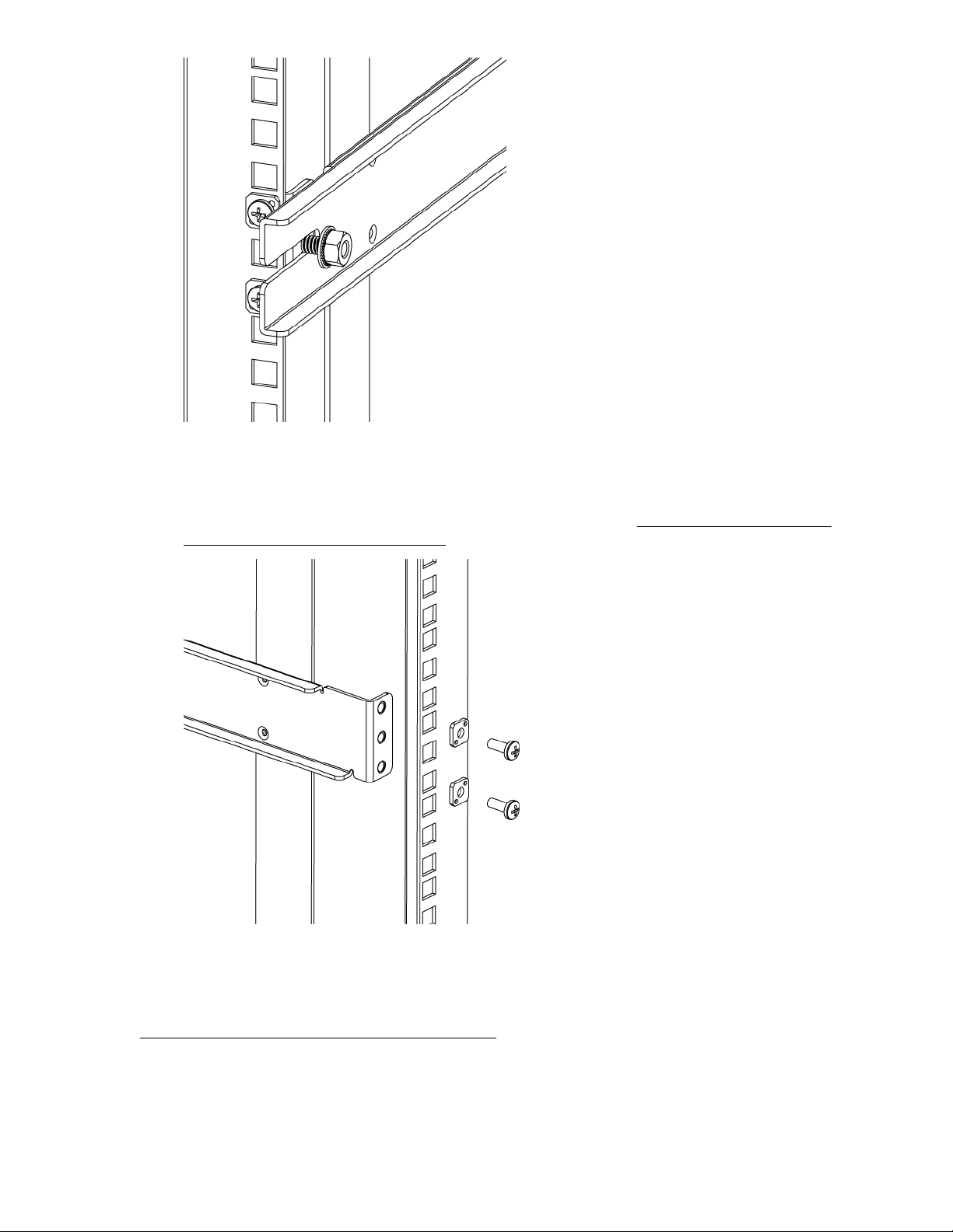
Figure 12: Installing the outer rails (HPE 10000 Series Rack)
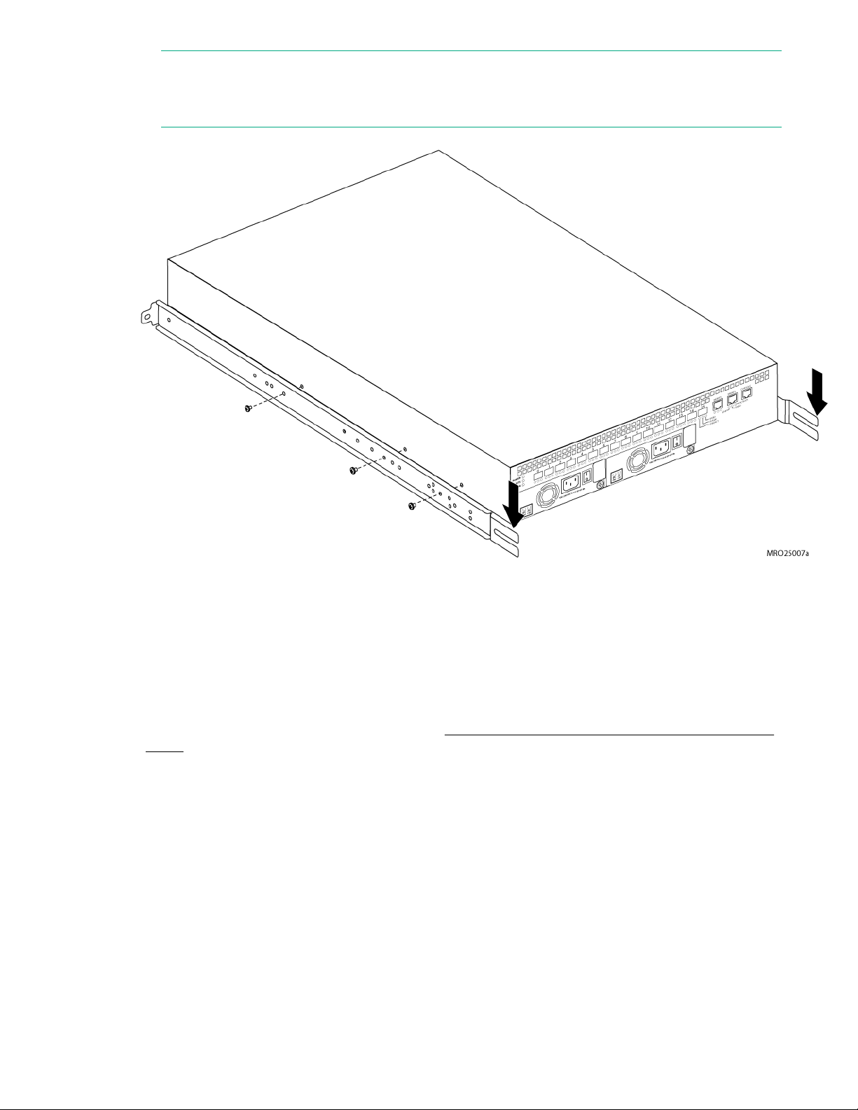
b. For an 10000 Series Rack, install two #10-32 x 1/2-inch Phillips panhead screws with captive star
lock washers and two #10 adapter washers in the upper and lower holes on the right rail. Then,
install two #10-32 x 1/2-inch Phillips panhead screws with captive star lock washers and two #10
adapter washers in the upper and lower holes on the left rail. See Figure 13: Assembling the
outer rails (HPE 10000 Series Rack) on page 30.
Figure 13: Assembling the outer rails (HPE 10000 Series Rack)
5. Use the #8-32 x 5/16-inch Phillips panhead SEMS screws (in the screw holes marked 16) to attach the
two inner rails to the switch. For switches with Port Side Air Intake, five screws are required for each
rail.
Figure 14: Attaching the inner rails to the switch on page 31 shows how the inner rails are attached
to the switch with the open ends (highlighted in yellow) on the port-side.
30 Installing and configuring HPE 16Gb FC switches
Page 31
NOTE:
The switch in the figure is not an StoreFabric SN6500B, but it shows the direction of the open ends
of the rails when they are attached to the switch.
Figure 14: Attaching the inner rails to the switch
Securing the switch to the outer rails
Procedure
1. Insert the switch with the attached inner rails into the outer rails.
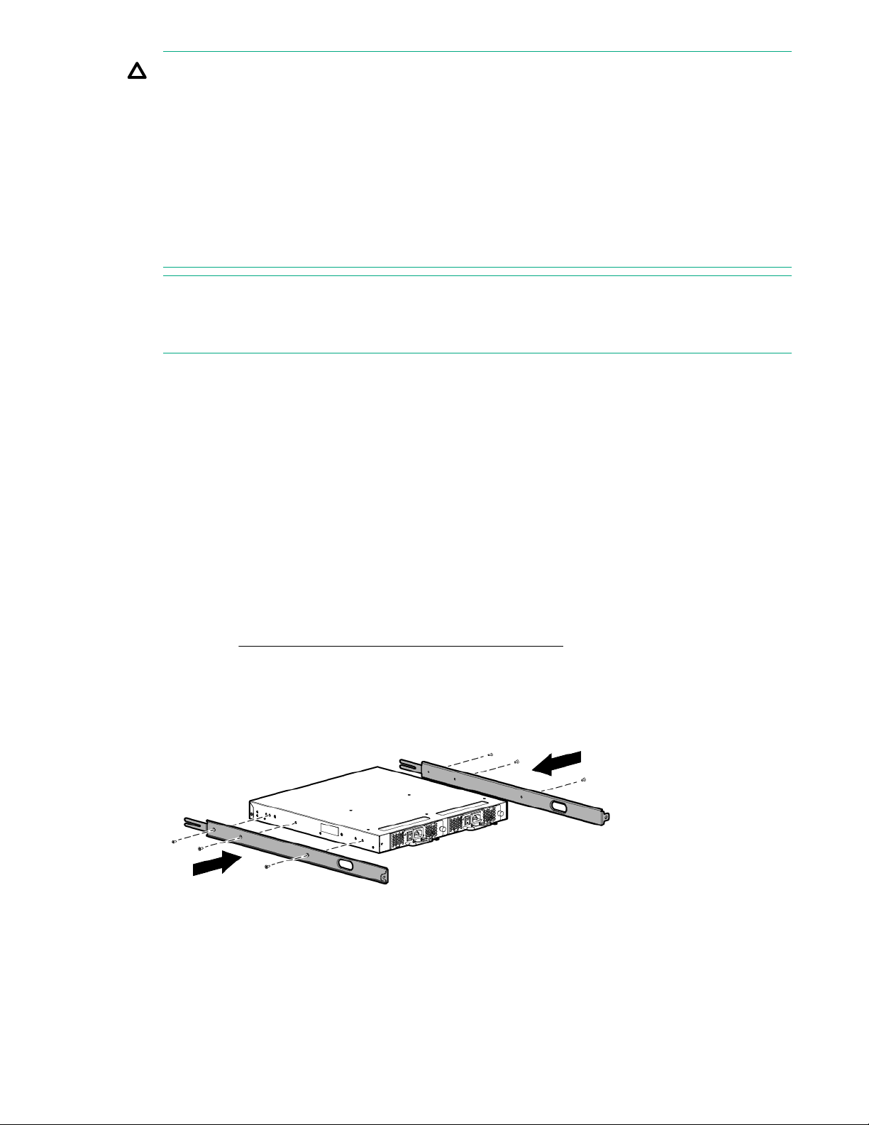
2. Insert the switch into the rack and install one #10-32 x 1/2-inch Phillips panhead screw with captive
star lock washer. Repeat for the other side. See Figure 15: Securing the switch (HPE 10000 Series
Rack) on page 32.
Securing the switch to the outer rails 31
Page 32
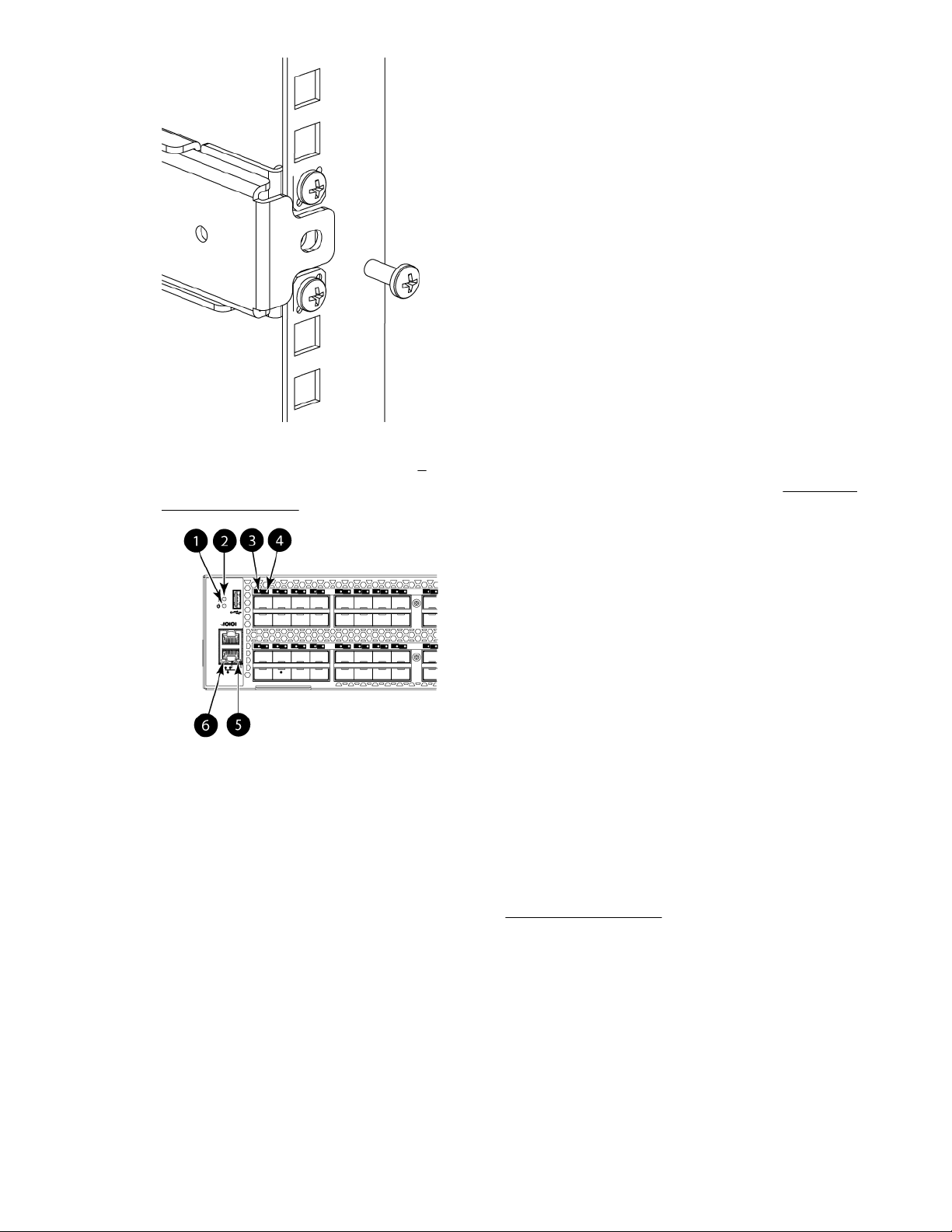
Figure 15: Securing the switch (HPE 10000 Series Rack)
3. Tighten the hex nuts installed in step 4 on page 29.
4. Verify that the switch power and status LEDs on the port side of the switch are green. See Figure 16:
LEDs on port side on page 32.
1. System power LED 2. System status LED
3. FC port status LED (port 0) 4. FC port status LED (port 4)
5. Ethernet port activity LED 6. Ethernet port speed LED
Figure 16: LEDs on port side
5. For switches with Port Side Air Intake, proceed to Setting up the switch on page 43.
This completes the rack mount procedure.
Installing the HPE SN6000B 16Gb FC and HPE SN3000B 16Gb FC switches in a rack using the Rack Mount Kit
Use the SN6000B and the SN3000B Switch Rack Mount Kits to install the switch in an 10000 Series
Rack.
32 Installing the HPE SN6000B 16Gb FC and HPE SN3000B 16Gb FC switches in a rack using the Rack
Mount Kit
Page 33
CAUTION:
Install the Rack Mount Kits as described in this section so that when the switch is installed, the port
side faces the rear of the rack. This configuration optimizes performance in the following ways:
• Provides better airflow by using a plenum. A plenum is an air duct that attaches to the switch
rails, enabling the switch to draw cooler air from outside the rack rather than drawing in heated
air from within the rack.
• Provides room for a gradual bend in the fiber optic cables because the port side of the switch is
set back from the edge of the rack.
Use only the screws provided in the Rack Mount Kit. Using other screws can cause damage to
internal components.
NOTE:
For switches with Port Side Air Intake, install the Rack Mount Kit so that when the switch is installed
the port side faces the front of the rack.
Installation safety guidelines
Verify that the rack and the area around the rack meet the following requirements:
• Plan a rack space that is a 1U high and provides clearance for the switch power cords to run between
the rack sides and the rails at the front of the 19-inch EIA rack.
• Ground all equipment in the rack through a reliable branch circuit connection and maintain ground at
all times. Do not rely on a secondary connection to a branch circuit, such as a power strip.
• Ensure that airflow and temperature requirements are met on an ongoing basis.
• Secure the rack to ensure stability in case of unexpected movement.
Rack mount installation
To install the switch in a rack using the Rack Mount Kit:
Procedure
1. Place the switch on a flat surface and attach each inner rail to the switch using three flat-head
screws. See Figure 17: Attaching the inner rails to the switch on page 33.
The rails are labeled Left and Right to designate the left side and right side of the switch as viewed
from its nonport side.
Figure 17: Attaching the inner rails to the switch
2. Take care to select a mounting location in the rack such that the cutouts in the sides of each rail are
not obstructed. You will route the switch power cords through these holes later in this procedure.
Installing and configuring HPE 16Gb FC switches 33
Page 34
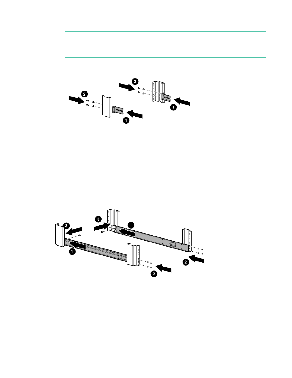
3. Attach each rear mounting bracket to a rear rack upright column using two Phillips screws and
adapter washers. See Figure 18: Installing the rear mounting brackets on page 34.
NOTE:
For switches with Port Side Air Intake, attach the rear mounting brackets to the front rack
upright column.
Figure 18: Installing the rear mounting brackets
4. Attach each outer rail as shown in Figure 19: Attaching the outer rails on page 34.
The rails are labeled Left and Right to designate the left side and right side of the rack as viewed
from the front of the cabinet.
NOTE:
For switches with Port Side Air Intake, attach Left outer rail to the right side of the rack and
Right outer rail to the left side of the rack.
Figure 19: Attaching the outer rails
a. Slide each rail over the rear mounting brackets.
b. Attach the front of the rail to a front rack upright column using two Phillips screws and adapter
washers.
c. Attach the outer rail to the rear mounting bracket using a Phillips screw.
34 Installing and configuring HPE 16Gb FC switches
Page 35
TIP:
Tighten the rear screws just enough for the end of the screw to go through the rear brackets.
Later in the procedure, you will need room to slide the inner rail between the screw head and
the outer bracket.
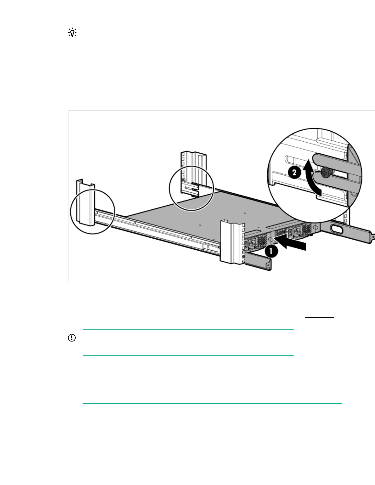
5. Install the switch. See Figure 20: Installing the switch in the rack on page 35.
a. From the front of the rack, slide the switch (with inner rails attached) onto the outer rails, taking
care to align the inner rails with the attachment screws on the outer rails at the rear of the rack.
b. When the switch is in place, secure the inner rails to the outer rails by tightening the screws at the
rear of the rack.
Figure 20: Installing the switch in the rack
6. At the front of the rack, run the switch power cords from the sides of the rack through the cutouts in
the rail, and then connect them to the switch power supplies. Connect two power cords to the
SN6000B 48-port switch. Connect one power cord to the SN3000B 24-port switch. See Figure 21:
Connecting power and installing the plenum on page 36.
IMPORTANT:
Make sure that the power cords do not come in contact with any sharp edges.
NOTE:
For switches with Port Side Air Intake, the power connections are at the rear of the rack.
If you are configuring the second (optional) power supply, the SN3000B 24-port switch will also
have two power cords.
Installing and configuring HPE 16Gb FC switches 35
Page 36
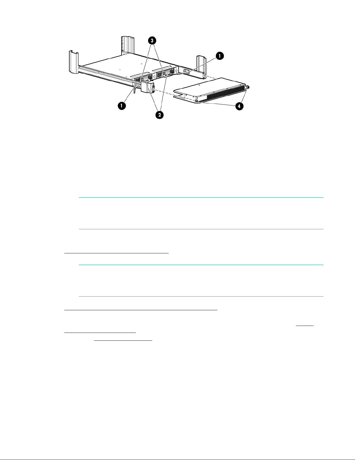
1. Cutouts for power cords 3. Power switches
2. Power cable plugs 4. Plenum thumb screws
Figure 21: Connecting power and installing the plenum
7. Connect the other end of the power cords to power sources on separate circuits to protect against
AC failure. (Make sure that two power cords are connected to the SN6000B 48-port switch and one
power cord is connected to the SN3000B 24–port switch.)
NOTE:
If you are configuring the second (optional) power supply, the SN3000B switch will also have
two power cords.
8. Power on the power supplies by setting both power switches to the ON (I) position.
The power supply LEDs are amber until the POST is complete, and then change to green. See
Power supply and fan assembly LEDs. The switch takes several minutes to boot and complete
POST.
NOTE:
When installed, the plenum covers the power supply switches and LEDs. However, the LEDs
are visible through the air holes in the front of the plenum.
9. Slide the plenum over the nonport side of the inner rails, taking care to bypass the power cables. See
Figure 21: Connecting power and installing the plenum on page 36.
10. Tighten the thumbscrews to secure the plenum to the front of the rack.
11. Verify that the switch power and status LEDs on the port side of the switch are green. See Figure
23: Port side status LEDs on page 37.
12. Proceed to Setting up the switch on page 43.
36 Installing and configuring HPE 16Gb FC switches
Page 37
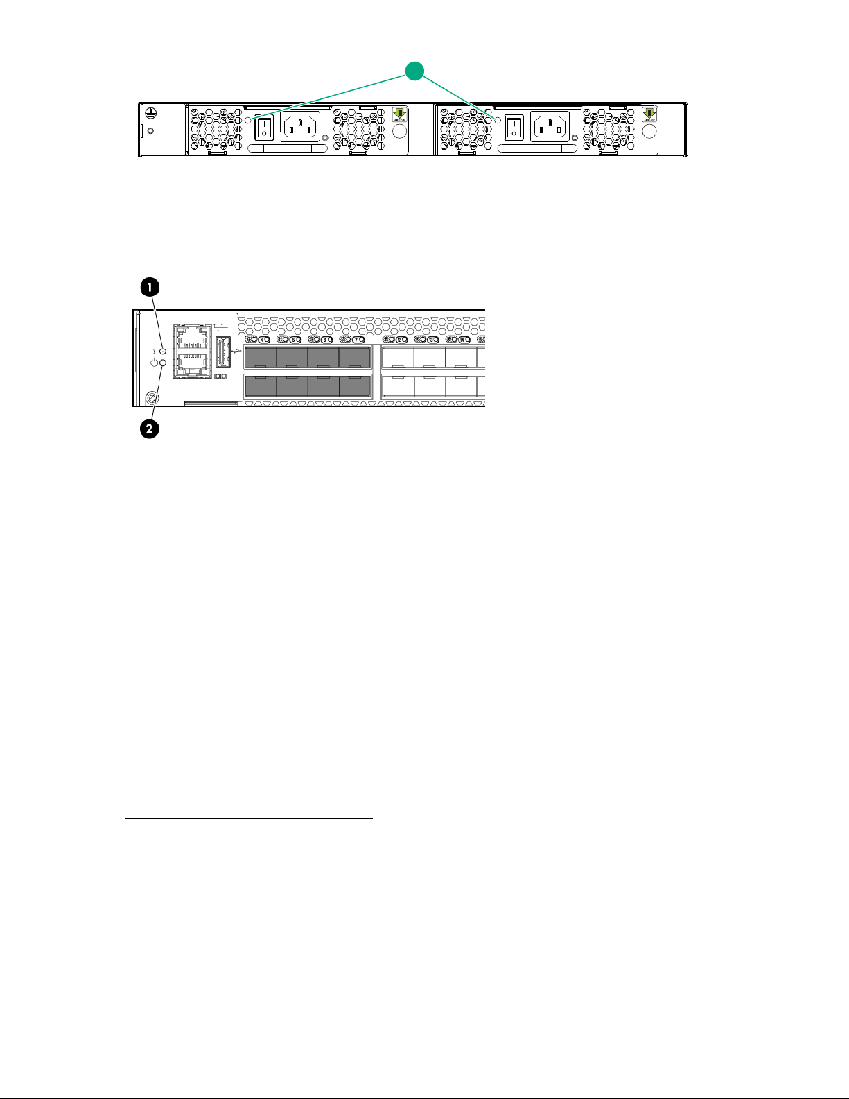
1
1. Power supply and fan assembly status LEDs
Figure 22: Power supply and fan assembly LEDs
1. System power LED
2. System status LED
Figure 23: Port side status LEDs
Installing the HPE StoreFabric SN4000B SAN Extension Switch
Use the SAN Switch Rack Mount Kit to install your Hewlett Packard Enterprise device in the 10000 Series
Rack custom rack.
For optimal cable management, Hewlett Packard Enterprise recommends that you install the SAN Switch
Rack Mount Kit to allow the nonport side of the switch to slide out of the cool-air side of the rack. In this
installation, the port-side of the switch is set back from the edge of the rack, allowing a more gradual bend
in the fiber optic cables.
The following items are required to install the switch in a rack:
• Power cables
• #2 Phillips screwdriver
• SAN Switch Rack Mount Kit hardware
SAN Switch Rack Mount Kit hardware identifies the rails and rail-mounting hardware.
Installing the HPE StoreFabric SN4000B SAN Extension Switch 37
Page 38
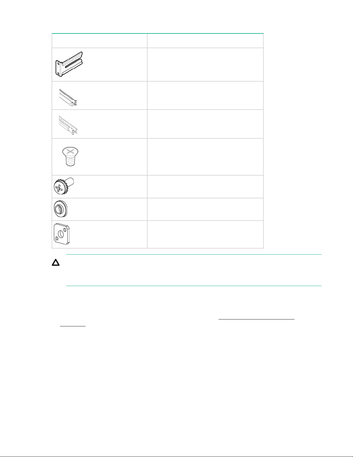
Table 7: SAN Switch Rack Mount Kit hardware
Item Description
Two rear mounting brackets
A right inner rail and a right outer rail
A left inner rail and a left outer rail
Sixteen #8-32 x 5/16-inch Phillips flathead
SEMS screws
Twelve #10-32 x 1/2-inch Phillips panhead
screws with captive star lock washers
To install the switch in a rack:
Procedure
1. Verify that the required parts and hardware are available. See SAN Switch Rack Mount Kit
2. Choose a mounting location for the switch in the rack.
Eight #10 alignment washers
Eight #10 adapter washers
CAUTION:
For proper airflow, the SFP+ media side of the switch port-side must face the rear of the rack. This
allows cool air to enter the front of the rack and exit from the rear.
hardware.
38 Installing and configuring HPE 16Gb FC switches
Page 39
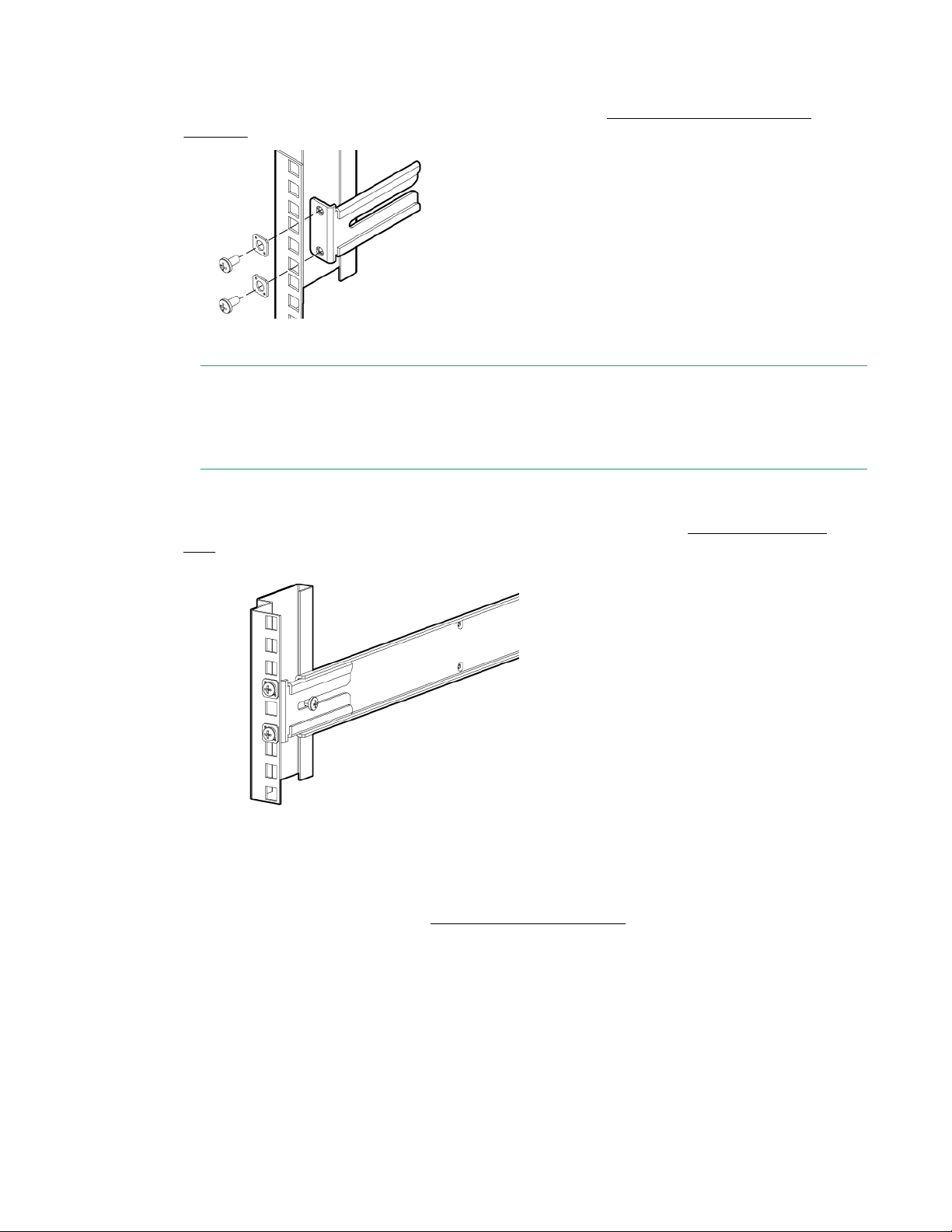
3. Attach the rear mounting brackets to the rear rack uprights.
• Assemble each of the brackets using two #10-32 x 1/2-inch Phillips panhead screws with captive
star lock washers and two #10 adapter washers, as shown in Installing the rear mounting
brackets.
Figure 24: Installing the rear mounting brackets
NOTE:
The SAN Switch Rack Mount Kit contains outer rails labeled Left and Right to designate the left
side and right side of the device or cabinet as viewed from the front of the cabinet. The inner rails
are interchangeable and can be used on either side of the switch.
4. Assemble the outer rails as follows:
a. Attach the left outer rail and right outer rail to the rear mounting brackets using the #10-32 x 1/2-
inch Phillips panhead screws with captive star lock washers, as shown in Installing the outer
rails. Four screws are required for attaching the outer rails.
Figure 25: Installing the outer rails
b. Install two #10-32 x 1/2-inch Phillips panhead screws with captive star lock washers and two #10
adapter washers in the upper and lower holes on the right rail. Then, install two #10-32 x 1/2-inch
Phillips panhead screws with captive star lock washers and two #10 adapter washers in the upper
and lower holes on the left rail. See Assembling the outer rails.
Installing and configuring HPE 16Gb FC switches 39
Page 40
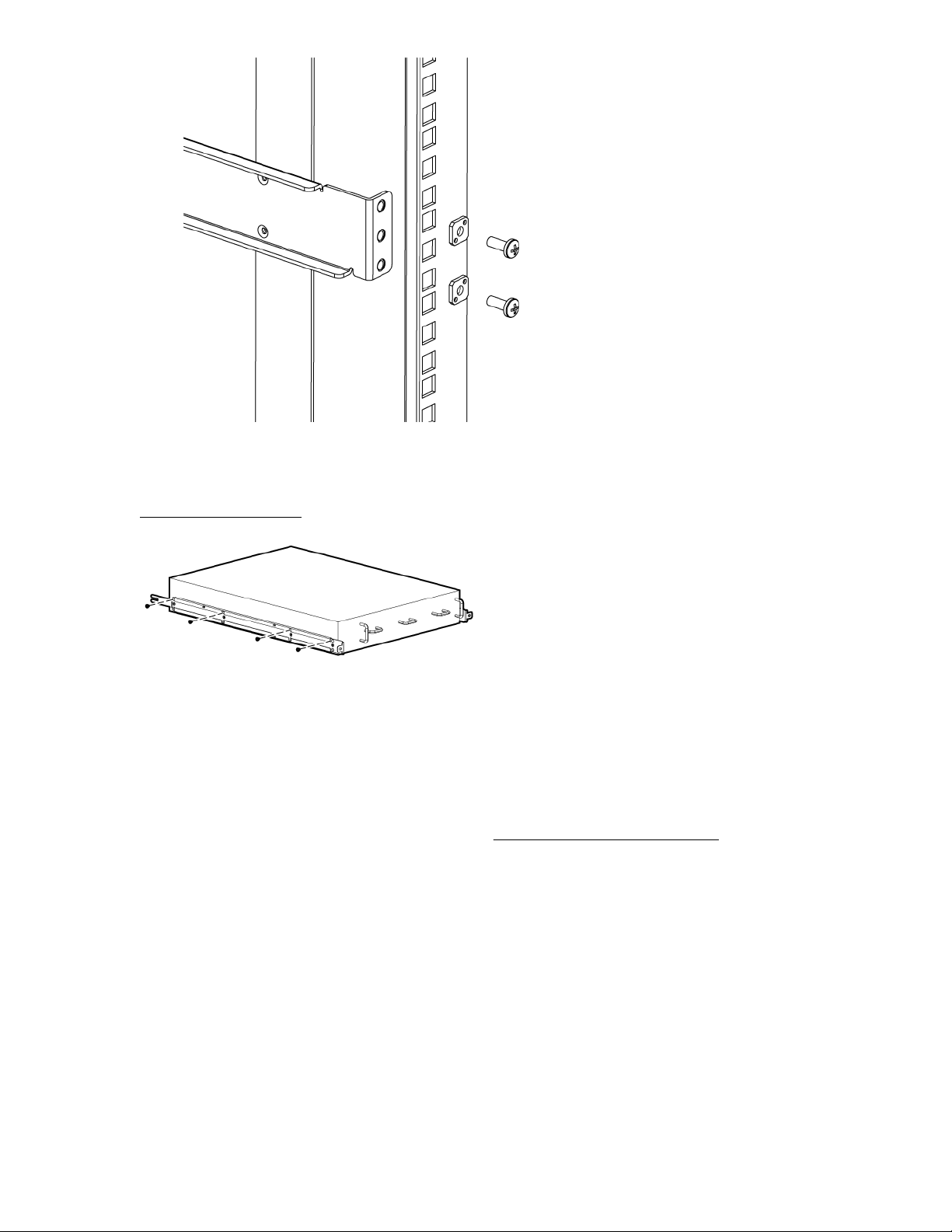
Figure 26: Assembling the outer rails
5. Use the screw type #8-32 x 5/16-inch (in the screw holes marked 16) to attach the two inner rails to
the switch. Eight screws are required for each rail.
Inner rails attachment shows how the inner rails are attached to the switch.
Figure 27: Inner rails attachment
Securing the switch to the outer rails
Procedure
1. Insert the switch with the attached inner rails to the outer rails.
2. Insert the switch into the rack and install one #10-32 x 1/2-inch Phillips panhead screw with captive
star lock washer. Repeat for the other side. See Figure 28: Securing the switch on page 41.
40 Securing the switch to the outer rails
Page 41
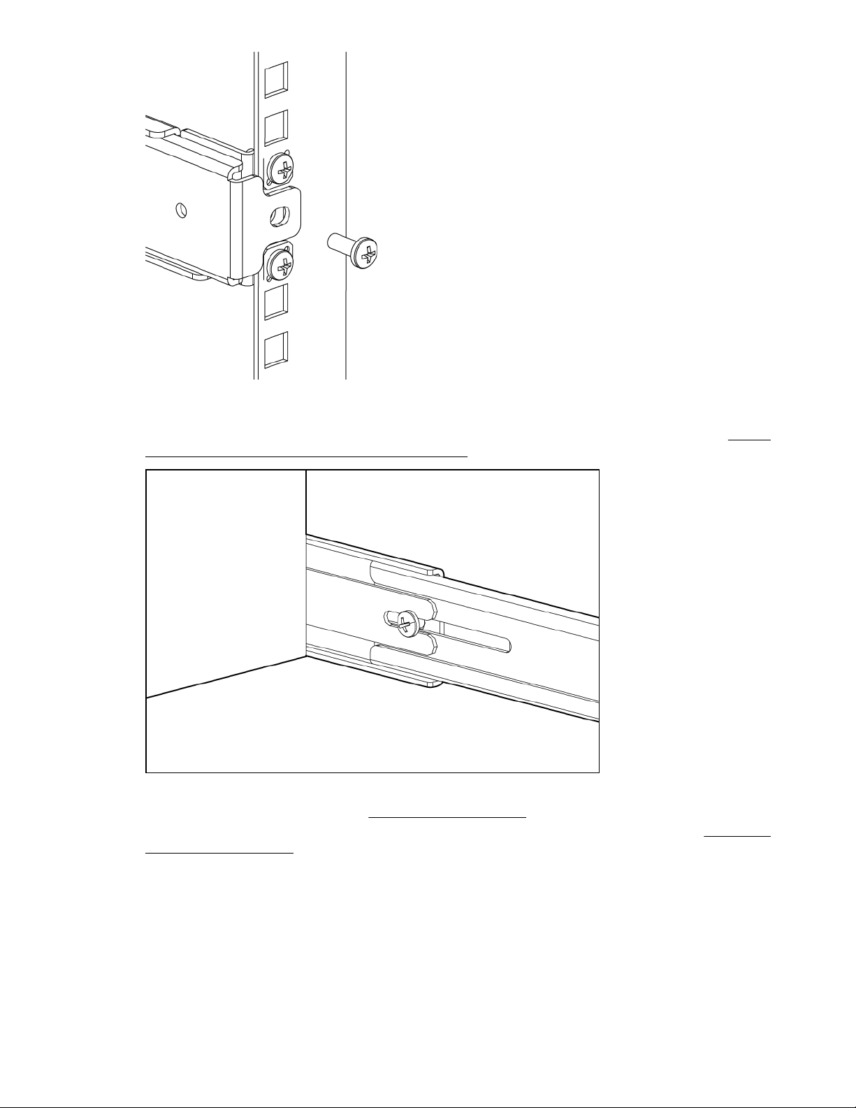
Figure 28: Securing the switch
3. Install one #10-32 x 1/2-inch Phillips panhead screw with captive star washer through the front of the
inner rail, through the rear bracket, and secure to the outer rail. Repeat for the other side. See Figure
29: Securing the front of the switch to outer rails on page 41.
Figure 29: Securing the front of the switch to outer rails
4. Tighten the screws as mentioned in Installing the outer rails.
5. Verify that the switch power and status LEDs on the port side of the switch are green. See Figure 30:
LEDs on the port side on page 42.
Installing and configuring HPE 16Gb FC switches 41
Page 42
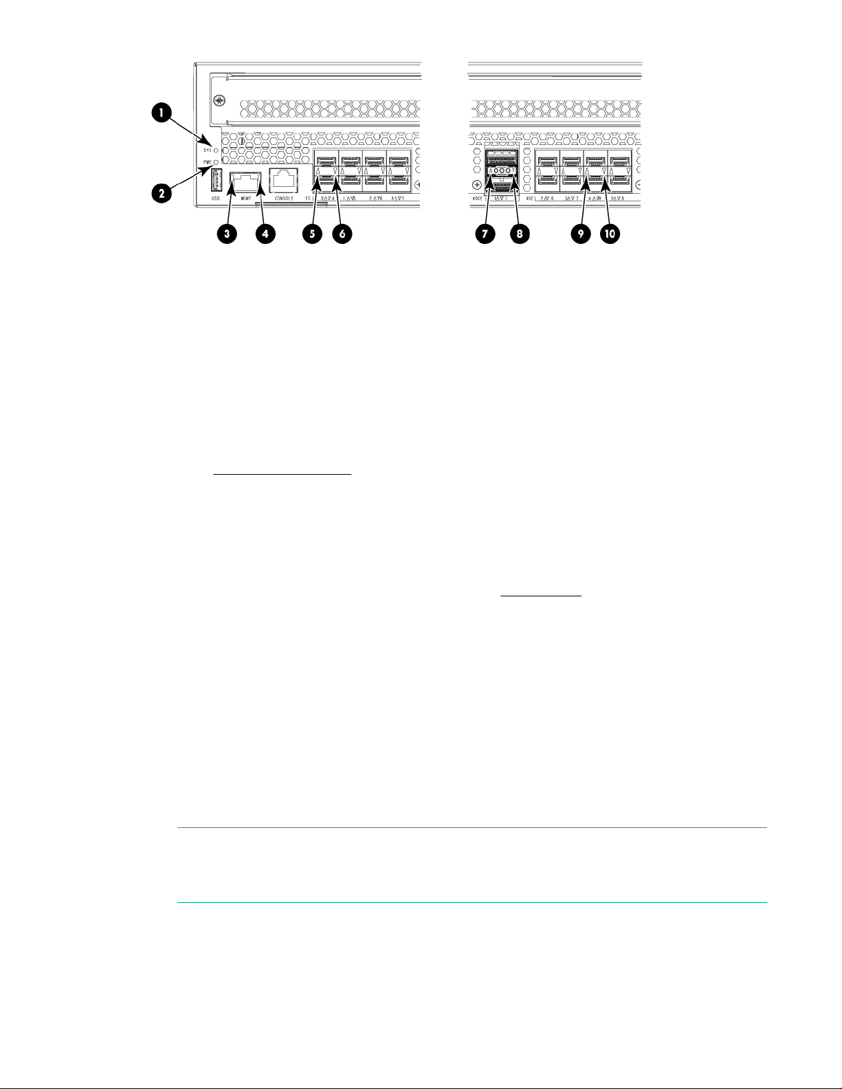
1. System status LED 2. System power LED
3. Ethernet link LED 4. Ethernet status LED
5. FC port status LED (port 0) 6. FC port status LED (port 4)
7. 40 GbE FCIP port status LED (port 0) 8. 40 GbE FCIP port status LED (port 1)
9. 1/10 GbE FCIP port status LED (port 4) 10. 1/10 GbE FCIP port status LED (port 8)
Figure 30: LEDs on the port side
6. Proceed to Setting up the switch on page 43.
This completes the rack mount procedure.
Installing a standalone switch
Procedure
1. Unpack the switch and verify the contents, as described in Accessories on page 24.
2. Apply the adhesive rubber feet to prevent the switch from sliding off the supporting surface.
a. Clean the indentations at each corner on the bottom of the switch to ensure that they are free of
dust or other debris.
b. With the adhesive side against the chassis, place one rubber foot in each indentation and press
into place.
3. Place the switch on a flat, sturdy surface.
4. Connect the power cords to each power supply present.
• For the SN6500B, SN6000B, and SN4000B switches, connect the power cords to both power
supplies and then to power sources on separate circuits to protect against AC failure.
• For the SN3000B switch, connect a power cord to either the single power supply present or to both
power supplies, if an optional second power supply is present. Then connect the power cords to
power sources on separate circuits to protect against AC failure.
NOTE:
If you are configuring the second (optional) power supply on the SN3000B switch, it will also
have two power cords.
Ensure that the cords have a minimum service loop of 6 inches available and are routed to avoid
stress.
5. Power on the power supplies by setting both AC switches to the on (|) position.
42 Installing a standalone switch
Page 43

The power supply LEDs are amber until POST is complete, and then change to green. See Power
supply and fan assembly LEDs. The switch takes several minutes to boot and complete POST.
NOTE:
Power is supplied to the switch as soon as the first power supply is connected and turned on.
6. After POST is complete, verify that the switch power and status LEDs on the port side of the switch
are green. See Figure 23: Port side status LEDs on page 37.
Setting up the switch
To set up the switch, you will need the following:
• Standard screwdriver
• WWN, located on the switch ID pull-out tab
• Ethernet connection (hub or switch)
• Ethernet and FC cables
• Disk array with FC ports
• Browser that allows pop-up windows
• If you are using static IP addressing, you will need the following items (not required if using DHCP):
◦ Fixed IP address (IPv4 or IPv6) for the switch
◦ Subnet mask value
◦ Default gateway value
Connecting the serial cable
Procedure
1. Connect the serial cable to the serial port on the switch and to an RS-232 serial port on the
workstation.
If the serial port is RJ-45 instead of RS-232, remove the adapter on the end of the serial cable and
insert the exposed RJ-45 connector into the RJ-45 serial port on the workstation.
2. Disable any serial communication programs running on the workstation.
3. Open a terminal emulator (such as HyperTerminal on a PC, or TERM, TIP, or Kermit in a UNIX
environment) and configure as follows:
For most Windows systems:
Bits per second: 9,600
Data bits: 8
Parity: None
Stop bits: 1
Flow control: None
For most UNIX systems:
Enter tip /dev/ttyb -9600
If ttyb is already in use, enter tip /dev/ttya -9600
Setting up the switch 43
Page 44

Logging in to the serial console port
Procedure
1. Verify that the switch has completed POST.
When POST is complete, the switch status and switch power LEDs return to a normal state.
2. When the terminal emulator stops reporting information, press Enter to display the login prompt.
3. Log in to the switch as admin, using the default password, password.
You are prompted to change the default password at initial login.
NOTE:
You can configure the switch using a static IP address or DHCP. With DHCP (enabled by default),
the switch obtains its IP address, subnet mask, and default gateway address from the DHCP server.
The DHCP client can connect only to a DHCP server that is on the same subnet as the switch. The
Ethernet cable must be connected to the management Ethernet port on the switch if you are using
DHCP. If you are using a static IP address, see Setting a static IP address.
Setting the IP address
You can configure the switch with a static IP address or you can use a DHCP server to set the IP
address. (DHCP is enabled by default.) The switch supports both IPv4 and IPv6.
Using DHCP to set the IP address
When using DHCP, the switch obtains its IP address, subnet mask, and default gateway address from the
DHCP server. The DHCP client can connect only to a DHCP server that is on the same subnet as the
switch. If your DHCP server is not on the same subnet as the switch, use a static IP address.
Setting a static IP address
Procedure
1. Use the ipaddrset command to set the Ethernet IP address.
• For an IPv4 address, use dotted-decimal notation:switch :admin> ipaddrset
• For an IPv6 address, use colon-separated notation:switch:admin> ipaddrset -ipv6 --add
1080::8:800:200C:417A/64
2. Provide the following network information for an IPv4 address:
a. Ethernet IP address: 192.168.74.102
b. Ethernet subnet mask: 255.255.255.0
c. Gateway IP address: 192.168.74.1
3. When prompted, enter off to disable DHCP:
DHCP [OFF]: off
4. Verify the IP address by entering the ipaddrshow command at the prompt.
5. Record the IP address on the pull-out tab on the port side of the switch.
6. If the serial port is no longer required, use the logout command to log out of the serial console.
Remove the serial cable and replace the plug in the serial port.
7. Connect the Ethernet port on the switch to the Ethernet network where the IP address was assigned.
44 Logging in to the serial console port
Page 45

Setting the date and time
The date and time are maintained by the switch's battery-backed RTC circuit. Incorrect date and time will
not affect switch operation. However, setting the date and time accurately is important because these
values are used for logging, error detection, and troubleshooting.
Setting the date
Procedure
1. Log in to the switch using the admin account. The default password is password.
2. Enter the date command:
date "mmddHHMMyy"
The values are as follows:
mm is the month; valid values are 01 through 12.
dd is the date; valid values are 01 through 31.
HH is the hour; valid values are 00 through 23.
MM is minutes; valid values are 00 through 59.
yy is the year; valid values are 00 through 99. (Values greater than 69 are interpreted as 1970 through
1999; values less than 70 are interpreted as 2000-2069.)
switch:admin> date
Fri Dec 30 17:01:48 UTC 2016
switch:admin> date "0109142417"
Mon Jan 9 14:24:00 UTC 2017
Setting the time zone
Users with administrative permissions can set the time zone for the switch by the zone name (such as
PST), by the country and city, or by time zone location (such as US/Central).
If you do not set the time zone, the switch retains the previous zone settings. The tstimezone
command includes an --old option, which reverts to the prior time zone format. For more information,
see the Fabric OS Command Reference.
The tstimezone command has three options:
Procedure
1. The tstimezonecommand with no parameters displays the current time zone setting.
2. The tstimezone --interactive command displays all time zones supported in the firmware.
3. The timeZone_fmt command sets the time zone based on the country and city, or a time zone ID,
such as PST, that you enter.
This command requires administrator privileges.
The time zone setting has the following characteristics:
• Automatically adjusts for Daylight Savings Time.
• Changing the time zone updates the local time zone setup and is reflected in local time calculations.
• By default, switches are in the GMT time zone (0,0). If all switches in a fabric are in one time zone, you
can keep the time zone setup at the default setting.
Setting the date and time 45
Page 46

• System services that have already started reflect the time zone changes only after the next reboot.
• In the event of failover, time zone settings are retained to ensure high availability.
You need only set the time zone once on each switch because the value is written to nonvolatile memory.
The following examples show how to set the time zone. The first example uses the time zone selection;
the second uses the country location selection.
The following procedure sets the current time zone to Central Standard Time using the timezone_fmt
command:
• Log in to the switch using the default password password.
• Use timezone_fmt to set the time zone by Country/City or by time zone ID, such as PST. The
following example shows how to change the time zone to US/Central:
switch:admin> tstimezone
Time Zone : US/Pacific
switch:admin> tstimezone US/Central
switch:admin> tstimezone
Time Zone : US/Central
The following procedure sets the time zone to Pacific Standard Time using interactive mode:
• Enter the tstimezone command:
• switch:admin> tstimezone --interactive
• A list of timezones appears followed by a prompt for you to select a general location:
• Please identify a location so that time zone rules can be set correctly.
• Enter the appropriate number (an offset of GMT) or press Ctrl+D to quit.
• At the prompt, select a country location.
• At the prompt, enter the appropriate number to specify the time zone region, or press Ctrl+D to quit.
Synchronizing local time
You can synchronize the local time of the principal or primary FCS switch to a maximum of eight external
NTP servers. To keep the time current in your SAN, Hewlett Packard Enterprise recommends that the
principal or primary FCS switch time is synchronized with at least one external NTP server. The other
switches in the fabric automatically take their time from the principal or primary FCS switch.
All switches in the fabric maintain the current clock server value in nonvolatile memory. By default, this
value is the local clock server LOCL of the principal or primary FCS switch. Changes to the clock server
value on the principal or primary FCS switch are propagated to all switches in the fabric.
When a switch has been added to the fabric, the time server daemon of the principal or primary FCS
switch sends the addresses of all existing clock servers and the time to that switch. If a switch running
Fabric OS 5.3.0 or later has been added to the fabric, it can store the list and the active servers. Switches
running Fabric OS 5.3.0 or earlier ignore the new list parameter in the payload and update only the active
server address.
If the active NTP server configured is IPv6, distributing the same information in the fabric is not possible
to switches running Fabric OS versions earlier than 5.3.0, because IPv6 is supported only for Fabric OS
version 5.3.0 and later. The default value LOCL is distributed to switches running Fabric OS 5.3.0 or
earlier.
The tsclockserver command accepts multiple server addresses in IPv4, IPv6, or DNS name format.
When multiple NTP server addresses are passed, tsclockserver sets the first obtainable address as
the active NTP server. The remaining addresses are stored as backup servers that can take over if the
active NTP server fails. The principal or primary FCS switch synchronizes its time with the NTP server
every 64 seconds.
46 Synchronizing local time
Page 47

Synchronizing local time using NTP
To synchronize the local time using NTP:
Procedure
1. Log in to the switch using the admin account. The default password is password.
2. Enter the tsclockserver command:
switch:admin> tsclockserver "<ntp1;ntp2>”
The value ntp1 is the IP address or DNS name of the first NTP server, which the switch must be able
to access. The value ntp2 is the name of the second NTP server and is optional. The entire operand
"<ntp1;ntp2>” is optional; by default, this value is LOCL, which uses the local clock of the principal
or primary switch as the clock server.
switch:admin> tsclockserver
LOCLx
switch:admin> tsclockserver "132.163.135.131"
switch:admin> tsclockserver
132.163.135.131
The following example shows how to set up more than one NTP server using a DNS name:
switch:admin> tsclockserver "10.32.170.1;10.32.170.2;ntp.localdomain.net"
Changes to the clock server value on the principal or primary FCS switch are propagated to all
switches in the fabric.
For more information on using an NTP server, and IPv6 considerations, see the Fabric OS
Administrator's Guide.
Configuring the zones and selecting devices
See the Fabric OS Administrator's Guide, Web Tools Administrator Guide, or Network Advisor user
manual, available from the Storage section of the Hewlett Packard Enterprise website:
http://www.hpe.com/support/manuals
Connecting devices
The Connect Devices window shows a graphical representation of the switch with the device
connections, based on the information that you entered in Configuring the zones and selecting
devices.
NOTE:
Only B-series optical transceivers are supported. For more information, see the Hewlett Packard
Enterprise website at http://www.hpe.com/support/SANcompatibility.
Consider the following when connecting devices:
• Transceivers and cables are keyed so that they can be inserted only one way. If a transceiver or cable
does not slide in easily, make sure it is oriented correctly.
• Do not insert a cable intended for an mSFP transceiver into a regular SFP+ transceiver; you may
damage the cable. The mSFP transceivers and cables are supported only with the 64-port 8 Gb/s
Synchronizing local time using NTP 47
Page 48
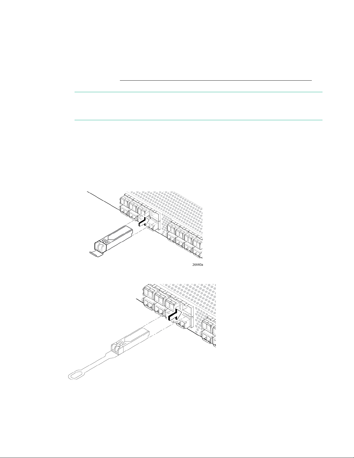
Procedure
1. Install the SFP+ transceivers in the FC ports on the switch to match the ports displayed in the Device
blade for the SN8000B SAN directors. Do not attempt to insert a standard SFP cable into an mSFP
transceiver; you can damage the transceiver.
Connection window.
If you are using an SFP+ transceiver that does not have a pull tab, ensure that the wire bail is in the
unlocked position. See Figure 31: Inserting an SFP+ transceiver with no pull tab in an FC port on
page 48.
NOTE: Each SFP+ transceiver has a 10-pad gold-plated PCB-edge connector on the bottom.
Insert an SFP+ transceiver into the upper row of ports with the gold edge down. Insert an SFP+
transceiver into the lower row of ports with the gold edge up.
a. Remove any protector plugs from the SFP+ transceiver. Insert each SFP+ transceiver (right side up
in the top row of ports, and upside down in the bottom row of ports) until it is firmly seated and the
latching mechanism clicks.
The 16 Gb/s SFP+ transceiver does not have a bail. Use the pull tab to push the transceiver into
the port.
b. Close the latching bail if there is one.
Figure 31: Inserting an SFP+ transceiver with no pull tab in an FC port
Figure 32: Inserting a 16 Gb/s SFP+ transceiver in an FC port
2. Connect the FC cables from the switch to your host and storage devices. Ensure that the physical
connections match the connections displayed in the Device Connection window.
48 Installing and configuring HPE 16Gb FC switches
Page 49

a. Remove the plastic protector caps from the FC cable ends (if there are any) and position the cable
connector so that it is oriented correctly.
b. Position a cable so that the key (the ridge on one side of the cable connector) is aligned with the
slot in the transceiver (see Figure 32: Inserting a 16 Gb/s SFP+ transceiver in an FC port on
page 48) .
c. Insert the cable into the transceiver until the latching mechanism clicks.
The Device Connection window shows missing, valid, and invalid connections as you cable the
switch. It can take up to 15 seconds for the screen to display the connection as valid.
d. Verify that the connections display green, and then click Next.
Setting switch features
See the Fabric OS 7.0.x Administrator's Guide and the Fabric OS 7.0.x Command Reference Manual for
detailed instructions on setting all supported switch features.
Switch status policy
Switch status policy is a feature that monitors different switch parameters such as power supplies and fan
units, and provides switch status based on their health.
The switch status policy configuration can be updated using the switchstatuspolicyset command.
The following example shows the default settings of 2 and 0 for DOWN and MARGINAL units for both Bad
Power Supplies and Bad Fans.
switch:admin>switchstatuspolicyset
some output skipped
The minimum number of
Bad PowerSupplies contributing to DOWN status: (0..2) [2]
Bad PowerSupplies contributing to MARGINAL status: (0..2) [0]
some output skipped
Bad Fans contributing to DOWN status: (0..2) [2]
Bad Fans contributing to MARGINAL status: (0..2) [0]
output truncated
If two power supply and fan assemblies are installed in the switch, Hewlett Packard Enterprise
recommends changing the configuration to 2 and 1 for DOWN and MARGINAL for both the Bad Power
Supplies and Bad Fans. Use the switchStatusPolicyShow command to see the results of your
changes.
Changing the switch name and chassis name
Changing the switch and chassis names is important for accurate tracking of errors in the RASlog. The
messages in the log are labeled with the switch or chassis name, so choose a meaningful name for the
switch and chassis.
Procedure
1. Using Telnet, log in to the switch as admin.
2. Use the chassisname command to change the chassis name.
The following example shows how to change the chassis name to myhpchassis.
switch:admin> chassisname myhpchassis
Setting switch features 49
Page 50

switch:admin> chassisname
myhpchassis
3. Use the switchname command to change the switch name. The following example shows how to
change the switch name to myhpswitch.
switch:admin> switchname myhpswitch
switch:admin> switchname
myhpswitch
Verifying the configuration
To confirm that the switch is configured and ready for use:
Procedure
1. Observe the LEDs to verify that all components are functional.
2. Issue the switchshow command from the workstation.
This command provides information about the switch and port status.
3. Issue the fabricshow command from the workstation.
This command provides general information about the fabric.
Backing up the configuration
Hewlett Packard Enterprise recommends regular backups to ensure that a recent configuration is
available.
Procedure
1. Enter the configupload command.
This command uploads the switch configuration to the server, making it available for downloading to a
replacement switch, if necessary. For instructions on backing up the configuration, see the Fabric OS
Administrator's Guide.
2. Follow the on-screen prompts.
Installing and activating Port Upgrade licenses
Procedure
1. Use the portshow command to verify the number of ports licensed on your switch.
The command output displays Started and Licensed for enabled ports. For more information on
this command, see the Fabric OS Command Reference Manual.
2. Obtain the WWN from the Switch ID pull-out tab located on the port side of your switch.
You can also use the switchshow command to display the WWN.
3. Contact your Hewlett Packard Enterprise representative to purchase the appropriate Port Upgrade
license. Hewlett Packard Enterprise requires the switch WWN obtained in
license key.
4. Install the license.
a. Log in to the switch as admin.
b. Enter the licenseadd command, followed by the license key enclosed in quotation marks.
2 on page 50 to assign a
50 Verifying the configuration
Page 51

The license key consists of approximately 16 uppercase and lowercase letters and numerals.
IMPORTANT:
Enter the license key exactly as issued. If you enter the key incorrectly, the license will not
function properly.
c. Enter the licenseshow command to verify that the license is valid.
If a licensed product is not displayed, the license is not valid.
NOTE:
You do not need to reboot the system.
5. Configure the inactive ports.
a. Enter the portstart command to start the ports. For example:
portstart 16–31
This command loads the port code, unlike the portenable command, which enables the port
laser.
b. Enter the portenable command to enable the ports. For example:
portenable 16–31
6. Optional: Enter the portshow command to verify that the newly activated ports have started.
Fabric OS Native and AG modes
The switch can function in either Fabric OS Native mode or AG mode. The switch is shipped in Native
mode by default.
• You can enable AG mode using Fabric OS commands or Web Tools.
• All POD licenses must be installed before you enable AG mode.
• When enabling AG mode, use the default F_Port-to-N_Port mappings or change this mapping using
the CLI or Web Tools, after configuring an IP address as described in Setting the IP address.
• AG simplifies SAN deployment by using NPIV. NPIV provides FC switch functions that improve switch
scalability, manageability, and interoperability.
◦ For a list of F_Ports mapped to N_Ports by default, see AG default port mapping on page 88.
◦ For general information and details on using AG, see the AG Administrator’s Guide.
NOTE:
AG cannot be connected directly to an array; it requires a fabric to support NPIV.
• The Fabric OS features available to the switch depend on whether the switch is configured in AG or
Native mode. For a list of available features for each mode, see the Access Gateway Administrator’s
Guide.
• In AG mode, cascading is not available for the switch. See the Access Gateway Administrator’s Guide
for details on any restrictions.
• In Native mode, the SN6000B switch provides up to 48 external FC ports and the SN3000B switch
provides up to 24 external FC ports. These universal self-configuring ports are capable of becoming
one of the following port types:
◦ F_Port (fabric enabled)
◦ FL_Port (fabric loop enabled)
Fabric OS Native and AG modes 51
Page 52

◦ E_Port (expansion port)
◦ M_Port (mirror port)
• In AG mode, the SN6000B switch provides up to 48 external FC ports and the SN3000B switch
provides up to 24 external FC ports. However, these ports are configured as N_Ports; you cannot
reconfigure them as any other port type.
Disabling and enabling AG mode
This section explains how to disable and enable AG mode using Fabric OS commands. For more
information on using these commands, see the Access Gateway Administrator’s Guide or see the Fabric
OS Administrator’s Guide.
NOTE:
You can disable and enable AG mode using Web Tools. For more information, see the Web Tools
Administrator’s Guide.
Enabling AG mode
Note the following when enabling AG mode:
• After you enable AG mode, some fabric information is erased, such as the zone and security
databases.
• Enabling AG mode is disruptive because the switch is disabled and rebooted.
• Ensure that no zoning or AD transaction buffers are active. If a transaction buffer is active, enabling
AG mode fails with the error Failed to clear Zoning/Admin Domain configuration.
To enable AG mode using Fabric OS commands:
Procedure
1. Before enabling AG mode, save the current configuration file using the configupload command.
2. Enter the switchshow command to verify the switch mode.
AG Mode is displayed for switchMode if the switch is in AG mode. Native is displayed for
switchMode if the switch is in Native mode.
3. Enter the switchdisable command to disable the switch.
The switch must be disabled in order to enable or disable AG mode.
4. Enter the ag -–modeenable command to enable AG mode.
5. Enter the ag --modeshow command to verify that AG mode is enabled.
switch:admin> ag --modeshow Access Gateway mode is enabled.
Disabling AG mode
When you disable AG mode, the switch reboots automatically and comes back online using the fabric
switch configuration. The AG parameters, such as F_Port-to-N_Port mapping, Failover, and Failback are
removed automatically. When the switch reboots, it starts in Native mode. For instructions on adding the
switch back to the core fabric, see the Access Gateway Administrator’s Guide.
To disable AG mode using Fabric OS commands:
Procedure
1. Enter the switchshow command to verify the switch mode.
AG Mode is displayed if the switch is in AG mode. Interopmode 0 or Native is displayed if the switch
is in Native mode.
2. Enter the switchdisable command to disable the switch.
52 Disabling and enabling AG mode
Page 53

The switch must be disabled in order to enable or disable AG mode.
3. Enter the ag --modeDisable command to disable AG mode.
4. Enter the ag --modeshow command to verify that AG mode is disabled.
switch:admin> ag --modeshow
Access Gateway mode is NOT enabled
Installing and configuring HPE 16Gb FC switches 53
Page 54
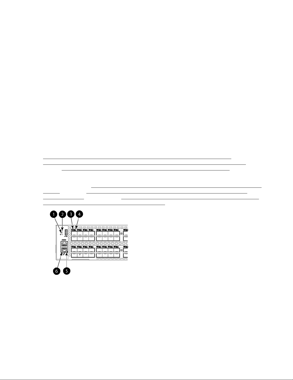
Operating HPE 16Gb FC switches
This chapter discusses switch power, LEDs, maintenance, and management.
Powering the switch on and off
• Power switches are located on the nonport side of the switch.
• If either the SN3000B or SN6000B 16Gb FC switch is mounted in a rack, you must remove the plenum
to access the power switches.
• Power is supplied to the switch as soon as the first power supply is connected and powered on.
• To power the switch off, power off the power supplies present by setting the AC power switch to O. All
devices are returned to their initial state the next time the switch is powered on.
LEDs
The switch LEDs indicate system activity and status. There are three LED states: no light, a steady light,
and a flashing light. Flashing lights can be slow, fast, or flickering. The lights are green or amber.
The LEDs can flash green or amber during boot, POST, or other diagnostic tests. This is normal; it does
not indicate a problem unless the LEDs do not indicate a healthy state after all boot processes and
diagnostic tests are complete.
Figure 33: LEDs on the port side of the HPE StoreFabric SN6500B 16Gb FC Switch on page 54,
Figure 34: LEDs on the port side of the HPE StoreFabric SN4000B SAN Extension Switch on page
55 , and Figure 37: Port side of the HPE SN6000B and SN3000B 16Gb FC switches on page 59
show the LEDs on the port side of the switches. The port status LEDs for the FC ports are arranged left to
right, and correspond to the upper and lower ports in each pair. The LEDs on the nonport side of the
switches are shown in Figure 35: LEDs on nonport side of the HPE StoreFabric SN6500B 16Gb FC
Switch on page 55, Figure 36: LEDs on nonport side of the HPE StoreFabric SN4000B SAN
Extension Switch on page 56 , and Power supply/fan assembly status LEDs on the nonport side
of the HPE SN6000B and SN3000B 16Gb FC switches .
1. System power LED 2. System status LED
3. FC port status LED (port 0) 4. FC port status LED (port 4)
5. Ethernet port activity LED 6. Ethernet port speed LED
Figure 33: LEDs on the port side of the HPE StoreFabric SN6500B 16Gb FC Switch
54 Operating HPE 16Gb FC switches
Page 55
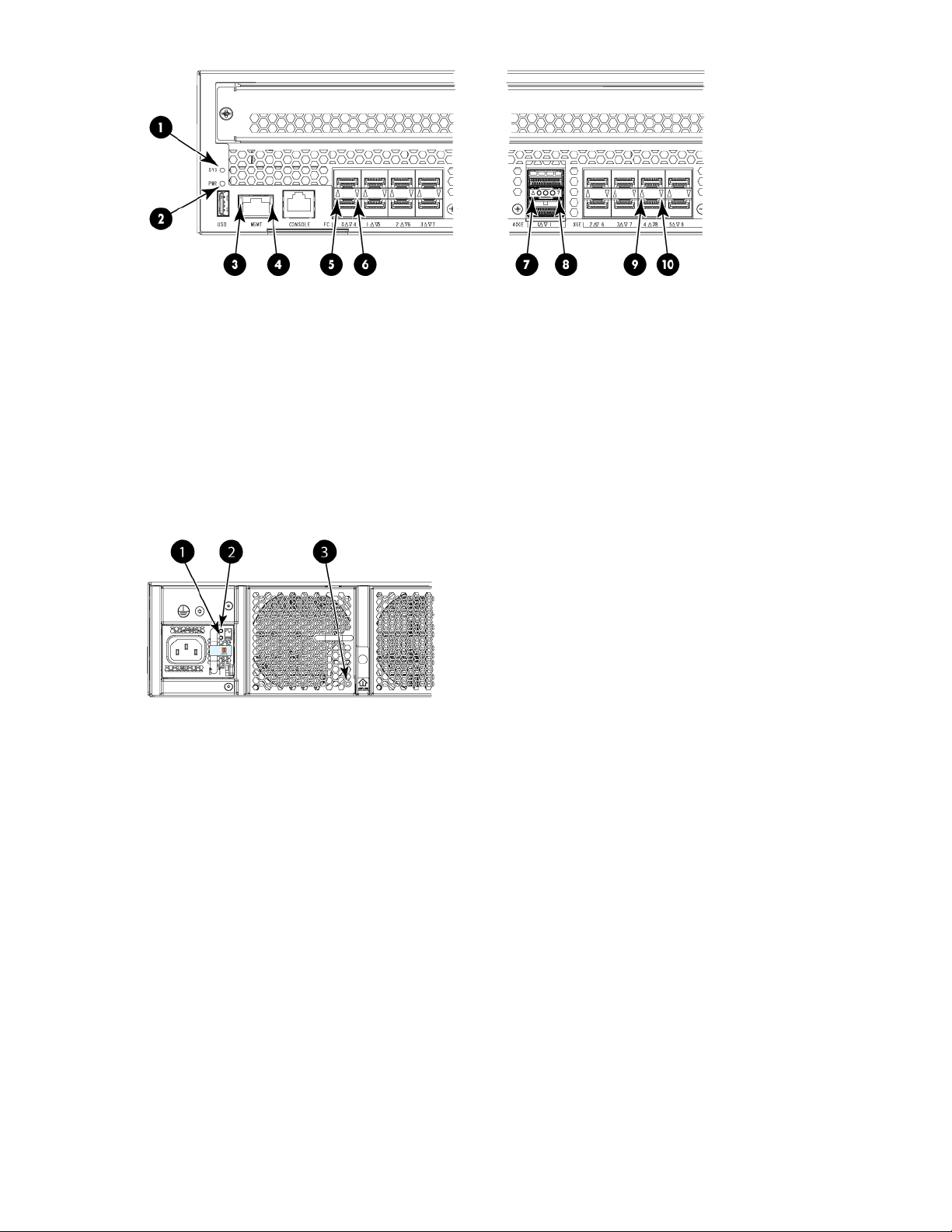
1. System status LED 2. System power LED
3. Ethernet link LED 4. Ethernet status LED
5. FC port status LED (port 0) 6. FC port status LED (port 4)
7. 40 GbE FCIP port status LED (port 0) 8. 40 GbE FCIP port status LED (port 1)
9. 1/10 GbE FCIP port status LED (port 4) 10. 1/10 GbE FCIP port status LED (port 8)
Figure 34: LEDs on the port side of the HPE StoreFabric SN4000B SAN Extension Switch
1. Power supply DC status LED 2. Power supply AC status LED
3. Fan status LED
Figure 35: LEDs on nonport side of the HPE StoreFabric SN6500B 16Gb FC Switch
Operating HPE 16Gb FC switches 55
Page 56
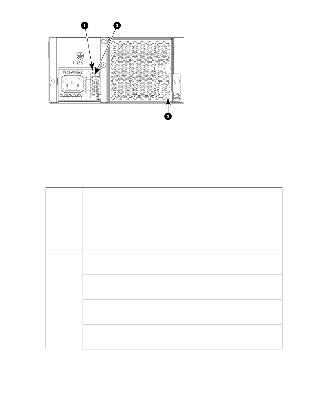
1. Power supply DC status LED 2. Power supply AC status LED
3. Fan status LED
Figure 36: LEDs on nonport side of the HPE StoreFabric SN4000B SAN Extension Switch
Table 8: LED patterns on the nonport side of the HPE StoreFabric SN6500B 16Gb
FC Switch and the HPE StoreFabric SN4000B SAN Extension Switch
LED name LED color Status of hardware Recommended action
Power
supply/AC
input status
(one green
LED)
Power
supply/DC
output status
(one bicolor
LED)
No light Power supply is not receiving
AC input voltage or AC input
voltage is below the operational
limit.
Steady green AC input voltage is within the
operational range.
Flashing
amber (1:1)
Flashing
amber/green
(2:1)
Flashing
amber/green
(1:1)
Steady amber Power supply is faulty or is not
Output voltage is not enabled. Verify that the power supply is
The temperature has exceeded
the threshold.
Internal fan is faulty. Replace the power supply.
plugged in completely.
Verify that the power supply is
seated correctly, and the power cord
is connected to a functioning AC
power source.
No action is required.
seated correctly and the captive
screw is secured.
Verify that the ambient temperature
is less than 40°C. Check for airflowintake blockage.
Check the power cord, current,
voltage, and temperature to
determine the problem.
56 Operating HPE 16Gb FC switches
Table Continued
Page 57

LED name LED color Status of hardware Recommended action
Fan assembly
status (one
bicolor LED)
Steady green DC output is within the expected
range.
No light Fan assembly is not receiving
power.
Steady green Fan assembly is operating
normally.
Steady amber
(for more than
5 seconds)
Fan fault for one of the following
reasons:
• A fan assembly with
mismatched airflow is
present.
• One or more of the fans in
the fan assembly has failed.
No action is required.
Verify that the fan FRU is seated
correctly.
No action is required.
Try one of the following:
• Replace the mismatched fan
assembly with one that has the
correct airflow direction.
• Replace the faulty fan assembly.
Table 9: LED patterns on the port side of the HPE StoreFabric SN6500B, SN6000B,
SN3000B, and SN4000B 16Gb FC switches
LED name LED color Status of hardware Recommended action
System power
(green)
System status
(bicolor)
No light System is off or there is an
internal power supply failure.
Steady green System is on and power
supplies are functioning
properly.
No light System is off or there is no
power.
Steady green System is on and is functioning
properly.
Steady amber
(for more than
5 seconds)
A system fault has occurred.
This LED is steady amber
during POST, which is normal
and does not indicate a fault.
Verify that the system is powered on
(power supply switches set to I), the
power cables are attached, and the
power source is live.
The unit may be faulty. Contact your
switch service provider.
No action is required.
Verify that the system is on and has
completed booting.
No action is required.
Check the failure indicated on the
system console.
Contact your switch service provider.
Table Continued
Operating HPE 16Gb FC switches 57
Page 58

LED name LED color Status of hardware Recommended action
Ethernet port
activity/link
Steady amber
(for more than
a few minutes)
Blinking
amber
No light There is no link. Verify that the Ethernet cable is
Steady green There is a link. No action is required.
Blinking green There is link activity (traffic). No action is required.
Unknown state, boot has failed,
or the system is faulty.
This may also be a result of
switch failure after completion of
POST.
Attention is required. There can
be a number of reasons for this
status, including a single power
supply failure, a fan failure, or
one or more environmental
ranges exceeded.
Perform the following steps:
1. Connect a serial cable to the
system.
2. Reboot the system.
3. Check the failure ndicated on the
system console.
4. Contact your switch service
provider.
Check the management interface
and the error log for details on the
cause of this status.
Contact your switch service provider.
connected correctly.
Ethernet port
speed
FC optical
media port
status (one
bicolor LED for
each FC port)
No light Port speed is 10 Mb/s. No action is required.
Steady green Port speed is 100 Mb/s.
For the StoreFabric SN6500B
16Gb FC Switch only, this
indicates a 100 or 1000 Mb/s
link.
Off There is no light or no signal
carrier on the media interface.
Steady amber Receiving light or carrier, but not
online.
Slow blinking
amber (2
seconds)
Fast blinking
amber (1/2
second)
Either the port has been
disabled by diagnostic tests
running or was disabled from
executing the
portdisable
CLI command.
There is a port failure. Check the management interface
No action is required.
Verify that the transceiver is installed
correctly and the cable is connected
correctly.
No action is required
Verify that the diagnostic tests are
not being run. Re-enable the port
using the
portenable
command.
and the error log for details on the
cause of the failure. Contact
technical support if necessary.
58 Operating HPE 16Gb FC switches
Table Continued
Page 59
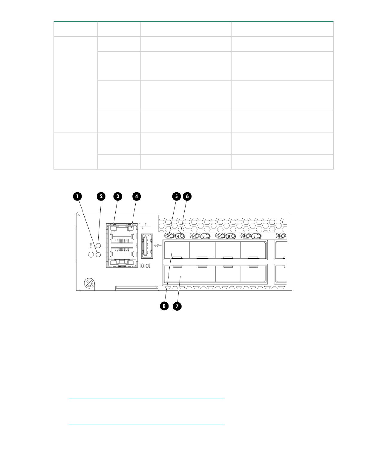
LED name LED color Status of hardware Recommended action
Steady green The port is online. No action is required.
Slow blinking
green (2
seconds)
Fast blinking
The port is online, but is
segmented due to a loopback
cable or incompatible switch.
Internal loopback (diagnostic). No action is required.
green (1/2
second)
10 GE/40 GE
Ethernet port
1
status
Flickering
green
No light The port is offline. There is no
The port is online, with frames
flowing through the port.
activity.
Steady green The port is online and active. No action is required.
1
This is applicable to the SN4000B SAN Extension Switch only.
No action is required.
No action is required.
Verify that the power LED is on.
Check the transceiver and the cable.
1. System power LED 2. System status LED
3. Ethernet port activity LED 4. Ethernet port speed LED
5. FC port status LED (port 0) 6. FC port status LED (port 4)
7. FC port 4 8. FC port 0
Figure 37: Port side of the HPE SN6000B and SN3000B 16Gb FC switches
NOTE:
The two LEDs on the serial console port are not functional.
Operating HPE 16Gb FC switches 59
Page 60
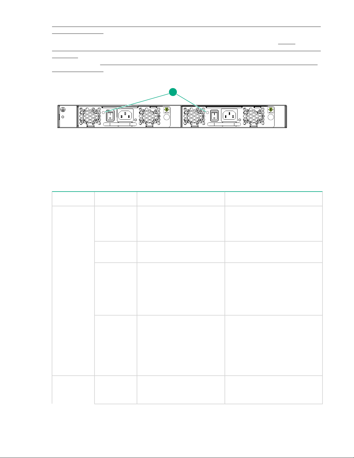
LED patterns on the port side of the HPE StoreFabric SN6500B, SN6000B, SN3000B, and SN4000B
1
16Gb FC switches describes the LED patterns on the port side of the switches.
The nonport side of the switches has one LED per Power supply and fan assembly. See Power
supply/fan assembly status LEDs on the nonport side of the HPE SN6000B and SN3000B 16Gb FC
switches . The standard configuration of the SN3000B 16Gb FC Switch includes a single Power supply
and fan assembly. LED patterns on the nonport side of the HPE SN6000B, SN3000B, and SN4000B
16Gb FC switches describes the LED patterns on the nonport side of the SN6000B and SN3000B 16Gb
FC switches.
1. Power supply and fan assembly status LEDs
Figure 38: Power supply/fan assembly status LEDs on the nonport side of the HPE SN6000B and SN3000B 16Gb FC switches
Table 10: LED patterns on the nonport side of the HPE SN6000B, SN3000B, and
SN4000B 16Gb FC switches
LED name LED color Status of hardware Recommended action
Power supply
and fan
assembly
status
No light Power supply/fan assembly is
not receiving power or is off.
Steady green Power supply/fan assembly is
operating normally.
Flashing green Power supply/fan assembly is
faulty.
When the switch is first powered
on, the power supply/fan
assembly status LED is flashing
green until POST is complete.
Steady amber
(for more than
5 seconds)
Fan fault for one of the following
reasons:
• A fan assembly with
mismatched airflow is
present.
• One or more of the fans in
the fan assembly has failed.
Verify that the power supply/fan
assembly is on and seated and the
power cord is connected to a
functioning power source.
No action is required.
Check the power cable connection.
Verify that the power supply/fan
assembly is powered on. Replace
the power supply/fan assembly
FRU.
Try one of the following:
• Replace the mismatched fan
assembly with one that has the
correct airflow direction.
• Replace the faulty fan assembly.
Power
supply/DC
60 Operating HPE 16Gb FC switches
Flashing
amber (1:1)
Output voltage is not enabled. Verify that the power supply is
seated correctly and the captive
screw is secured.
Table Continued
Page 61

LED name LED color Status of hardware Recommended action
output status
(one bicolor
LED)
Flashing
amber/green
(2:1)
Flashing
amber/green
(1:1)
Steady amber Power supply is faulty or is not
Steady green DC output is within the expected
The temperature has exceeded
the threshold.
Internal fan is faulty. Replace the power supply.
plugged in completely.
range.
POST and boot specifications
When the switch is powered on or rebooted, it performs POST. Total boot time with POST can be several
minutes. POST can be omitted after subsequent reboots by using the fastboot command or entering
the diagDisablePost command to persistently disable POST. For more information about these
commands, see the Fabric OS 7.0.x Command Reference Manual.
POST
Verify that the ambient temperature
is less than 40°C. Check for airflowintake blockage.
Check the power cord, current,
voltage, and temperature to
determine the problem.
No action is required.
You can monitor the results of the diagnostic tests that run during POST through LED activity, the error
log, or the CLI. POST includes the following tasks:
• Conducting preliminary POST diagnostics
• Initializing the operating system
• Initializing hardware
• Running diagnostic tests on several functions, including circuitry, port functionality, memory, statistics
To determine whether POST completed successfully:
Procedure
1. Inspect the switch LEDs to determine whether components are operating properly.
2. Verify that the switch prompt is displayed on a workstation connected to the switch.
3. Review the switch system log for errors.
counters, and serialization
See LED patterns on the port side of the HPE StoreFabric SN6500B, SN6000B, SN3000B, and
SN4000B 16Gb FC switches and LED patterns on the nonport side of the HPE SN6000B,
SN3000B, and SN4000B 16Gb FC switches for descriptions of LED patterns. If one or more LEDs do
not display a healthy state, verify that the LEDs are not set to beacon by entering the switchshow
command to detect if beaconing is active.
If there is no switch prompt when POST is complete, press Enter. If the switch prompt still does not
appear, open a Telnet session or access the switch through another management tool. If this does not
solve the problem, the switch did not complete POST successfully. Contact your switch supplier for
repair.
Any errors detected during POST are written to the system log, accessible through the errShow
command.
For information about error messages, see the Fabric OS Message Reference Manual.
POST and boot specifications 61
Page 62

Boot
Boot occurs after POST is complete and includes the following tasks:
• Performing universal port configuration.
• Initializing links.
• Analyzing the fabric.
If any ports are connected to other switches, the switch participates in a fabric configuration.
• Obtaining a domain ID and assigning port addresses.
• Constructing unicast routing tables.
• Enabling normal port operation.
Switch maintenance
The switch supports only Hewlett Packard Enterprise-branded 8 Gb/s and 16 Gb/s SFP+ optical
transceivers. For the FC connections, the switch uses SFP+ transceivers that support any combination of
SWL, LWL, and ELWL optical media.
If you use an unqualified transceiver, the switchshow command output shows the port in a Mod_Inv
state. Fabric OS also logs the issue in the system error log.
For information about installing transceivers, see
Diagnostic tests
In addition to POST, Fabric OS includes diagnostic tests to help you troubleshoot the hardware and
firmware. This includes tests of internal connections and circuitry, fixed media, and transceivers and
cables.
The tests are implemented by command through a Telnet session or a console set up to the serial
connection to the switch. Some tests require that ports be connected by external cables in order to verify
the serializer/deserializer interface, transceiver, and cable. Some tests require loopback plugs.
Diagnostic tests run at a link speed of 2, 4, 8, 10, or 16 Gb/s (FC), depending on the speed of the link
being tested and the type of port.
NOTE:
• Diagnostic tests can temporarily lock the transmit and receive speed of the links.
• Hewlett Packard Enterprise does not support 2 Gb/s connectivity to the StoreFabric SN4000B,
SN6500B, SN6000B, and SN3000B 16Gb FC switches.
For information about specific diagnostic tests, see the Fabric OS Troubleshooting and Diagnostics
Guide.
Switch management
Connecting devices.
You can use the management functions built into the switch to monitor the fabric topology, port status,
physical status, and other information to help you analyze switch performance and to accelerate system
debugging.
For information about upgrading the Fabric OS version installed on your switch, see the Fabric OS
Administrator’s Guide.
You can manage the switch using any of the management tools listed in Switch management tools. For
more information on the CLI commands, see the Fabric OS 7.3.x Command Reference Manual.
62 Boot
Page 63
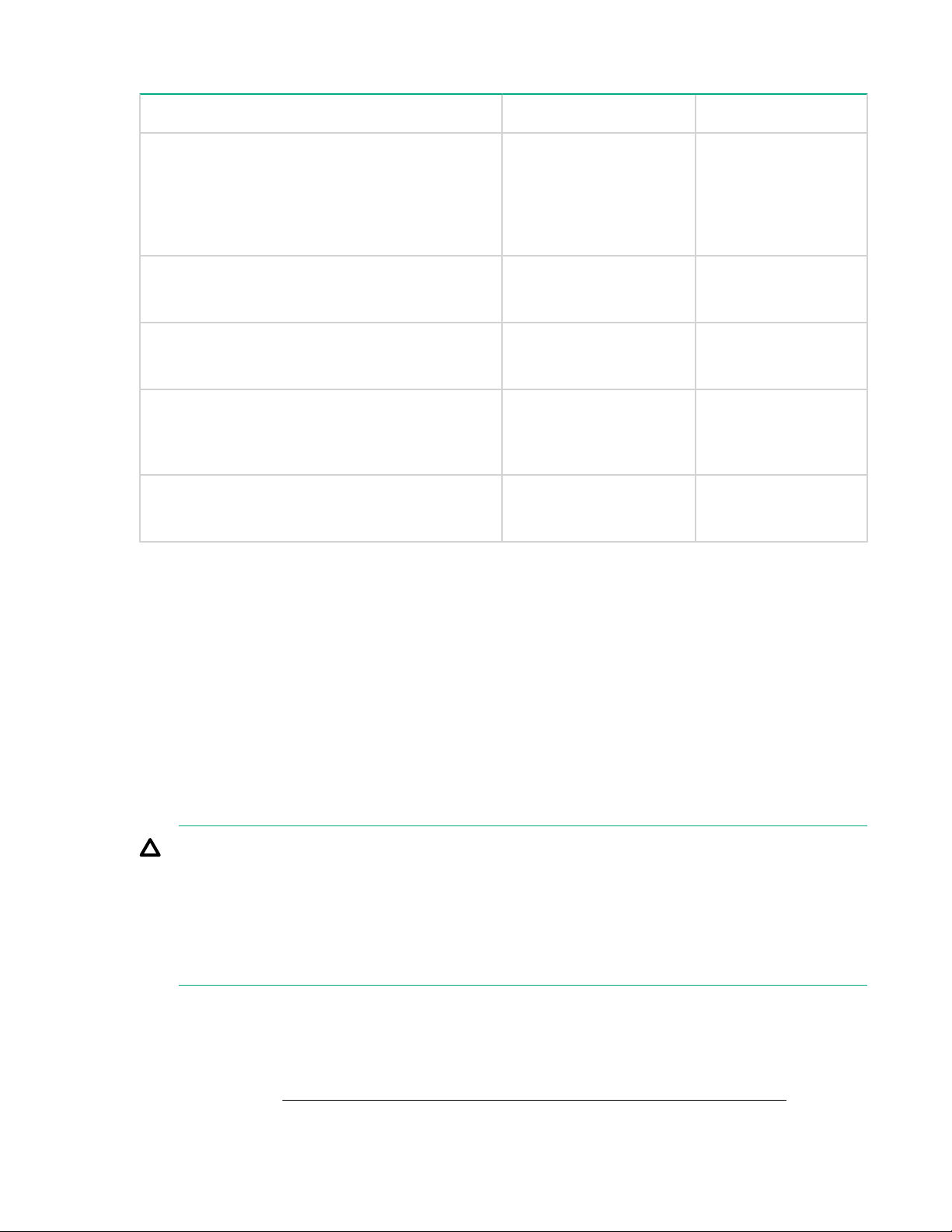
Table 11: Switch management tools
Management tool Out-of-band support In-band support
CLI
Up to two admin sessions and four user sessions
simultaneously. See the Fabric OS Administrator’s
Guide and the Fabric OS 7.3.x Command
Reference Manual.
Web Tools
See the Web Tools Administrator’s Guide.
Standard SNMP applications
See the MIB Reference Manual.
Management Server
See the Fabric OS Administrator’s Guide and the
Fabric OS 7.3.x Command Reference Manual.
Network Advisor (option to purchase)
See the Network Advisor documentation set.
FRU removal and replacement
Ethernet or serial
connection
Ethernet or serial
connection
Ethernet or serial
connection
Ethernet or serial
connection
Ethernet or serial
connection
IP over FC
IP over FC
IP over FC
Native in-band
interface (over HBA
only)
IP over FC
No special tools are required to remove and replace the power supply and fan assembly FRU for the
following switches:
• SN6000B 16Gb FC Switch
• SN3000B 16Gb FC Switch
• StoreFabric SN6500B 16Gb FC Switch
• StoreFabric SN4000B SAN Extension Switch
The switches will continue to operate during the FRU replacement if you follow the procedures in this
chapter. However, the SN3000B 16Gb FC Switch will continue to operate normally only if it has two power
supplies installed. The SN3000B 16Gb FC switch comes with only one power supply by default and if
removed will have no power. Replacing a power supply and fan assembly takes less than two minutes.
CAUTION:
Disassembling any part of the power supply voids the part warranty and regulatory certifications.
There are no user-serviceable parts inside the power supply and fan assembly. The cooling system
relies on pressurized air, so do not leave either of the power supply and fan assembly slots empty
longer than two minutes when the switch is operating. If a power supply and fan assembly fails,
leave the power supply and fan assembly in the switch until it can be replaced. The power supply
and fan assembly must be operational to ensure redundancy.
Replacing the HPE StoreFabric SN6500B 16Gb FC Switch or the HPE StoreFabric SN4000B SAN Extension Switch power supply
The StoreFabric SN6500B 16Gb FC and the StoreFabric SN4000B SAN Extension switches have two
power supplies (see Figure 39: HPE StoreFabric SN6500B 16Gb FC Switch power supply on page
FRU removal and replacement 63
Page 64

66 and Figure 40: HPE StoreFabric SN4000B SAN Extension Switch power supply on page 66).
The Fabric OS identifies power supplies from left to right on the nonport side as power supply #2 and
power supply #1.
See this cautionary note before beginning replacement "CAUTION".
See LED patterns on the nonport side of the HPE StoreFabric SN6500B 16Gb FC Switch and the
HPE StoreFabric SN4000B SAN Extension Switch for the power supply status LED colors, patterns,
and recommended actions, if any.
Determining the need to replace a power supply
Use one of the following methods to determine the status of the power supplies:
• Check the power supply AC status and DC status LEDs; both should be green. See
for more information. If the DC status LED is amber, there is no power running through the cord.
• In Web Tools, click the Power Status icon.
• At the command prompt, enter the psShow command to display the power supply status:
Example of the psShow command for the StoreFabric SN6500B 16Gb FC Switch:
Switch:admin> psshow
Power Supply #1 is OK
Airflow Direction : Portside Intake (Forward)
Power Supply #2 is OK
Airflow Direction : Portside Intake (Forward) Switch:admin>
WARNING:
You must disconnect the power cords from all power sources to completely remove power from the
chassis.
Before beginning the power supply replacement
CAUTION:
Hewlett Packard Enterprise only supports the port-side exhaust configuration, and only offers the
port side exhaust fan FRU. The following information is provided only for reference.
LEDs on page 54
When replacing a failed power supply or fan, the new FRU must have the same part number as the
FRU it is replacing. The manufacturing part number is located on the top of the FRU.
Both the power supply and fan FRUs are labeled with an airflow symbol on the faceplate to indicate
whether the fan assembly pulls in or exhausts air. These labels also appears on the top of the fan
assembly. All fan assemblies and power supplies must have the same airflow symbol (E or I) to be
compatible with each other.
Examples of airflow symbols
64 Determining the need to replace a power supply
Page 65
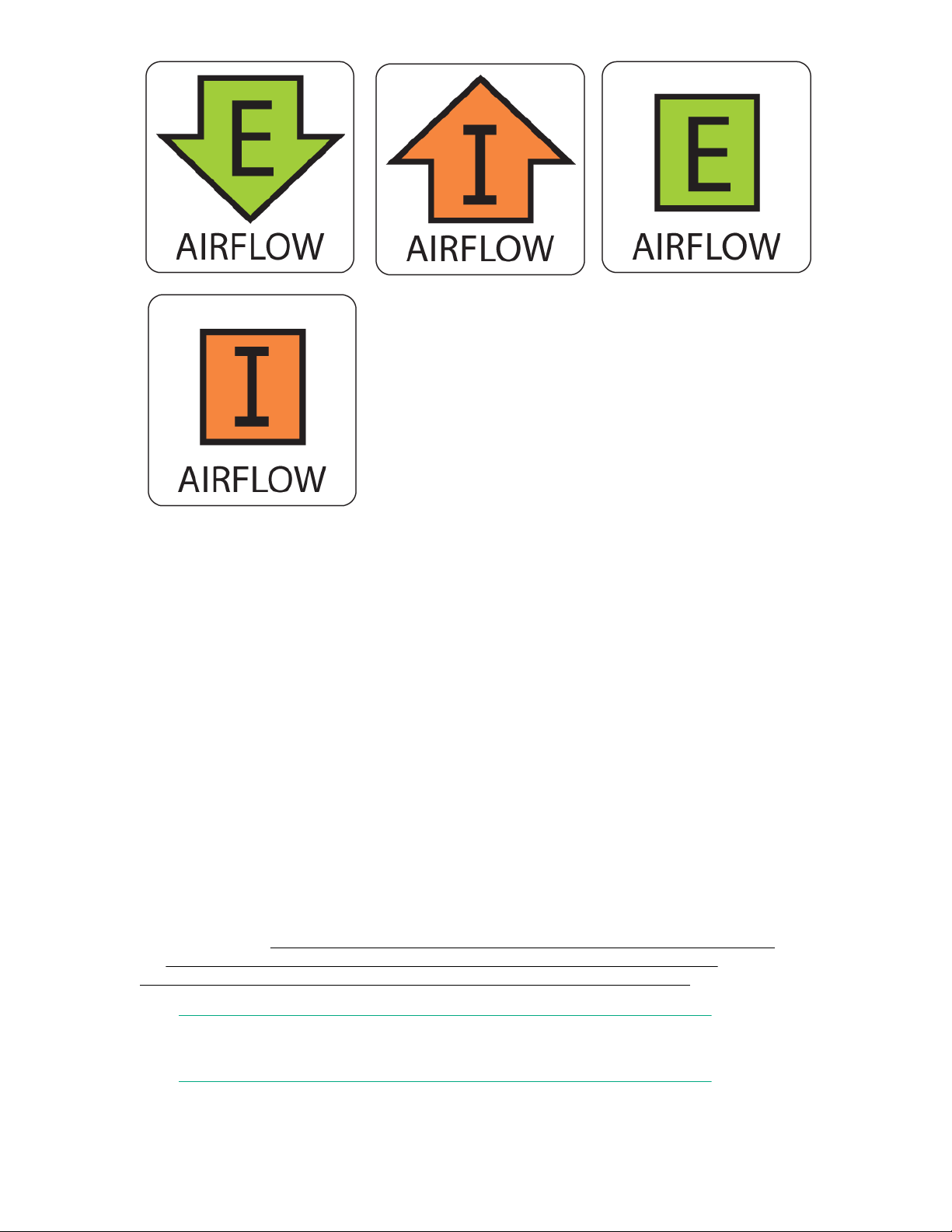
Some information to note:
• The green E symbol indicates an exhaust unit. This unit pulls air in from the port-side of the switch and
exhausts it out the nonport side. This is also called front-to-back airflow or forward airflow. This symbol
should appear on FRUs with part numbers ending with -F.
• The orange I symbol indicates an intake unit. This unit pulls air in from the nonport side of the switch
and exhausts it out the port-side. This is also called back-to-front airflow or reverse airflow. This
symbol should appear on FRUs with part numbers ending with -R.
• The chassisShow command will indicate either forward or reverse airflow.
• If one fan fails, the remaining fans go to high speed to maintain proper cooling until the failed fan is
replaced.
• If a mismatched power supply or fan assembly is installed by mistake, a critical error message is sent
to the console. The message will be similar to the following:
CRITICAL HIL-1611 MISMATCH in PSU/FAN Air Flow direction. Replace PSU with
fan air flows in same direction. System will be shut down in 2 minutes.
Replacing a power supply
Replacing a power supply in the StoreFabric SN6500B 16Gb FC Switch or the StoreFabric SN4000B
SAN Extension Switch should require less than two minutes to complete.
The new power supply must have the same part number and airflow indicator as the power supply you
are replacing. See Figure 39: HPE StoreFabric SN6500B 16Gb FC Switch power supply on page
66, Figure 40: HPE StoreFabric SN4000B SAN Extension Switch power supply on page 66, and
Figure 41: HPE StoreFabric SN4000B SAN Extension Switch airflow labels on page 67 for the
power supply details and the location of the airflow labels.
NOTE:
Hewlett Packard Enterprise only supports the port side exhaust power supply.
Replacing a power supply 65
Page 66
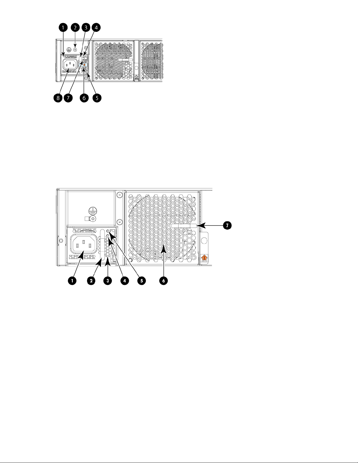
1. Power supply #2 2. Grounding screw
3. Handle 4. AC input status LED
5. Locking tab 6. Airflow label
7. DC output status LED 8. Power cord receptacle
Figure 39: HPE StoreFabric SN6500B 16Gb FC Switch power supply
1. AC power socket 2. Handle
3. Integral fan air inlet 4. DC status LED
5. AC status LED 6. Fan air inlet
7. Handle
Figure 40: HPE StoreFabric SN4000B SAN Extension Switch power supply
66 Operating HPE 16Gb FC switches
Page 67
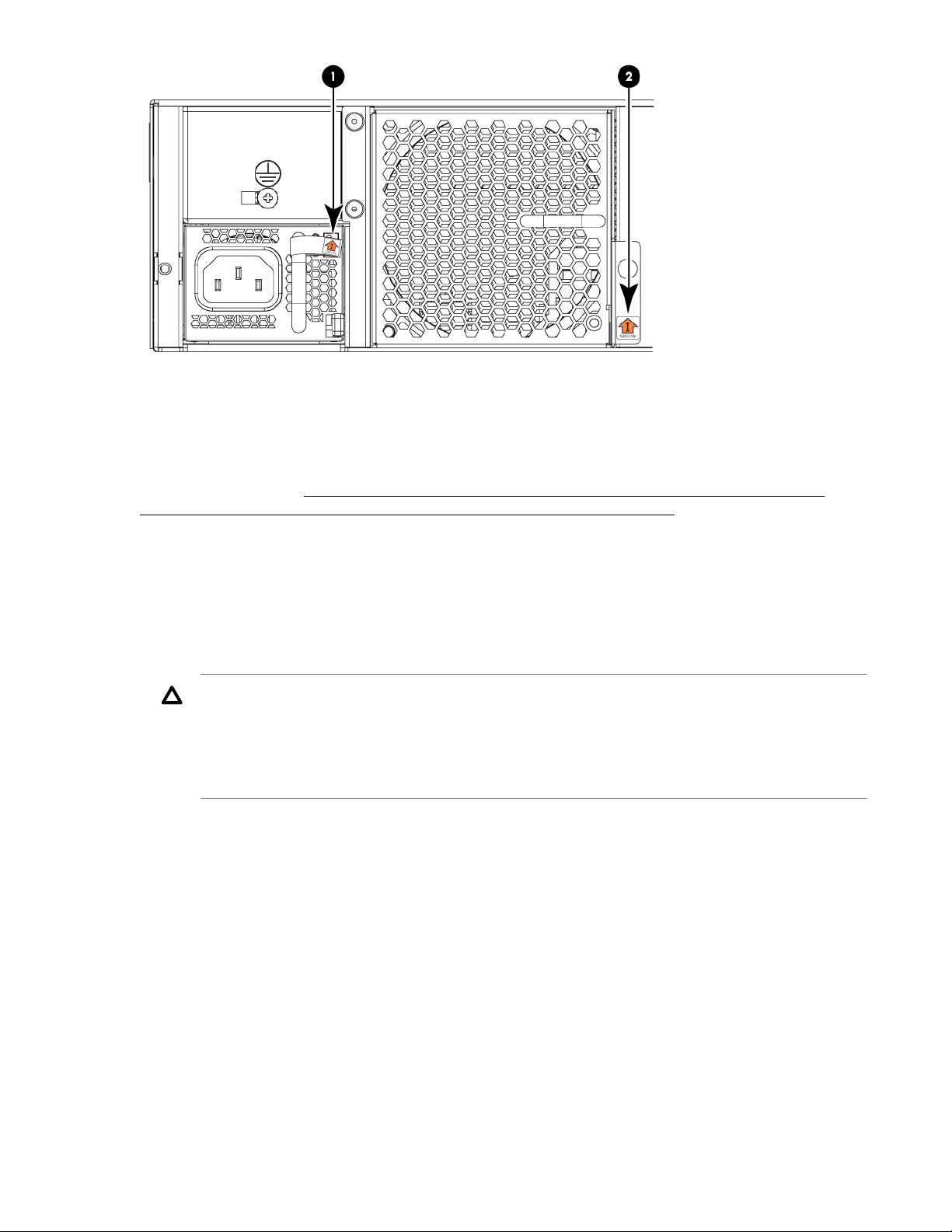
1. Airflow label for PSU integral fan 2. Airflow label for fan FRU
Figure 41: HPE StoreFabric SN4000B SAN Extension Switch airflow labels
To replace a power supply in the StoreFabric SN6500B 16Gb FC Switch or the StoreFabric SN4000B
SAN Extension Switch (
16Gb FC Switch or the HPE StoreFabric SN4000B SAN Extension Switch on page 68):
1. Verify that the second power supply has been powered on for at least four seconds, and that the LED
is steady green. This ensures the switch remains in service while replacing a power supply.
2. Unplug the power cord from the power supply that is being replaced.
3. Push the locking tab to the left and hold it there, and use the handle on the power supply to pull it
straight out and away from the chassis. Pull the power supply out slowly to avoid catching a finger on
the locking tab.
4. Slide the new power supply into the chassis until the locking tab engages.
CAUTION:
• Do not force the power supply into the chassis. If the power supply does not slide in easily,
ensure that it is oriented correctly before continuing.
• After replacing the power supply, if the switch powers down after two minutes, it is probably
because the new power supply has a mismatched airflow.
5. Plug the power cord into the power supply to power on the unit.
If the power was on before the replacement, the power supply will attempt to power up immediately.
Figure 42: Inserting the power supply in the HPE StoreFabric SN6500B
Operating HPE 16Gb FC switches 67
Page 68
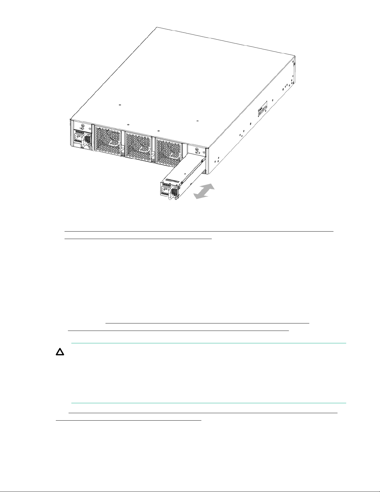
Figure 42: Inserting the power supply in the HPE StoreFabric SN6500B 16Gb FC Switch or the HPE StoreFabric SN4000B SAN Extension Switch
6. Verify that the LEDs on the new power supply are steady green when the switch is operating. See
LED patterns on the nonport side of the HPE StoreFabric SN6500B 16Gb FC Switch and the
HPE StoreFabric SN4000B SAN Extension Switch for more information. If the LEDs are not steady
green, ensure that the power supply is installed securely.
Optionally, using the CLI, enter the psShow command or chassisShow command to display the
power supply status.
You can also use Web Tools to view the power supply status.
Replacing an HPE StoreFabric SN6500B 16Gb FC Switch or an HPE StoreFabric SN4000B SAN Extension Switch fan
The StoreFabric SN6500B 16Gb FC and the StoreFabric SN4000B San Extension switches have three
fans, as shown in
and Figure 10: Nonport side of the StoreFabric SN4000B SAN Extension Switch on page 22. The
Fabric OS identifies the fan locations from left to right as fan #3, fan #2, and fan #1.
CAUTION:
Disassembling any part of the fan assembly voids the part warranty and regulatory certifications.
There are no user-serviceable parts inside the fan. Because the cooling system relies on
pressurized air, do not leave any of the fan slots empty for longer than two minutes while the switch
is operating. If a fan fails, leave it in the switch until it can be replaced.
Figure 2: Nonport side of HPE SN6500B StoreFabric 16Gb FC Switch on page 9
Maintain all three fans in operational condition to ensure redundancy.
See LED patterns on the nonport side of the HPE StoreFabric SN6500B 16Gb FC Switch and the
HPE StoreFabric SN4000B SAN Extension Switch for the power supply status LED colors, patterns,
and recommended actions, if any.
68 Replacing an HPE StoreFabric SN6500B 16Gb FC Switch or an HPE StoreFabric SN4000B SAN
Extension Switch fan
Page 69

Determining the need to replace a fan
Use one of the following methods to determine the status of the fans:
• Check the fan status LED. See LEDs on page 54 for more information.
• In Web Tools, click the Power Status icon for the StoreFabric SN6500B 16Gb FC Switch.
For the StoreFabric SN4000B SAN Extension Switch, click the Fan Status icon.
• At the command prompt, enter the fanShow command to display the fan status.
NOTE:
Fans 4 and 5 are integral to the power supplies. These fans typically operate at approximately
12,000 RPM. The system fans of the StoreFabric SN6500B 16Gb FC switch typically operate at
approximately 2,000 RPM, while the system fans of the StoreFabric SN4000B SAN Extension
Switch operate at around 4,000 RPM. If there is a problem with fan 4 or 5, see Replacing the HPE
StoreFabric SN6500B 16Gb FC Switch or the HPE StoreFabric SN4000B SAN Extension
Switch power supply on page 63.
Example of the fanShow command for the StoreFabric SN6500B 16Gb FC switch:
Switch:admin> fanshow Fan 1 is Ok, speed is 1965 RPM Fan 2 is Ok, speed is
2011 RPM Fan 3 is Ok, speed is 2011 RPM Fan 4 is Ok, speed is 12001 RPM Fan 5
is Ok, speed is 11995 RPM Switch:admin>
Replacing an HPE StoreFabric SN6500B 16Gb FC Switch or an HPE StoreFabric SN4000B SAN Extension Switch fan
Replacing a fan requires the following:
• A new fan with the same part number and airflow indicator as the fan being replaced. See
HPE StoreFabric SN6500B 16Gb FC Switch fan on page 70 and Figure 41: HPE StoreFabric
SN4000B SAN Extension Switch airflow labels on page 67 for the location of the airflow labels.
• A #1 Phillips screwdriver.
NOTE:
Hewlett Packard Enterprise only supports the port-side exhaust fans, and only offers the port-side
exhaust fan FRU option. This information is provided for reference only.
Figure 43:
Determining the need to replace a fan 69
Page 70
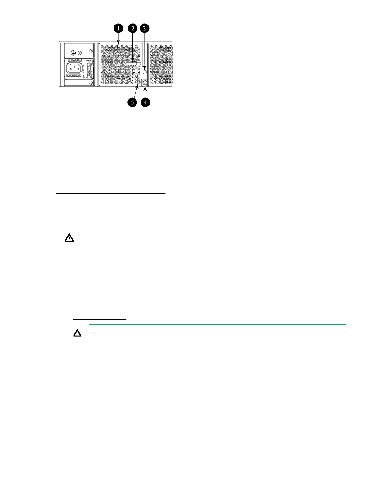
1. Fan #3 2. Handle
3. Captive screw 4. Airflow label
5. Status LED
Figure 43: HPE StoreFabric SN6500B 16Gb FC Switch fan
For the StoreFabric SN4000B SAN Extension Switch fan, see Figure 40: HPE StoreFabric SN4000B
SAN Extension Switch power supply on page 66.
To replace a fan (Figure 44: Inserting the fan in the HPE StoreFabric SN6500B 16Gb FC Switch or
the HPE StoreFabric SN4000B SAN Extension Switch on page 71):
1. Using the Phillips screwdriver, unscrew the captive screw on the fan.
WARNING:
Do not insert your fingers in the fan while removing it from the chassis. The fan may still be
spinning at a high speed.
2. Remove the fan from the chassis by using the handle on the fan to pull it straight out and away from
the chassis.
3. Install the new fan in the chassis:
a. Verify that the airflow direction is the same as that of the fan you are replacing.
b. Orient the new fan with the captive screw on the right, as shown in Figure 44: Inserting the fan in
the HPE StoreFabric SN6500B 16Gb FC Switch or the HPE StoreFabric SN4000B SAN
Extension Switch on page 71.
CAUTION:
• Do not force the power supply into the chassis. If the fan does not slide in easily, ensure
that it is oriented correctly before continuing.
• After replacing a fan, if the switch powers down after 2 minutes, it is probably because the
new fan has a mismatched airflow.
c. Gently push the fan into the chassis until it is firmly seated.
d. Using the Phillips screwdriver, secure the fan to the chassis by tightening the captive screw.
70 Operating HPE 16Gb FC switches
Page 71
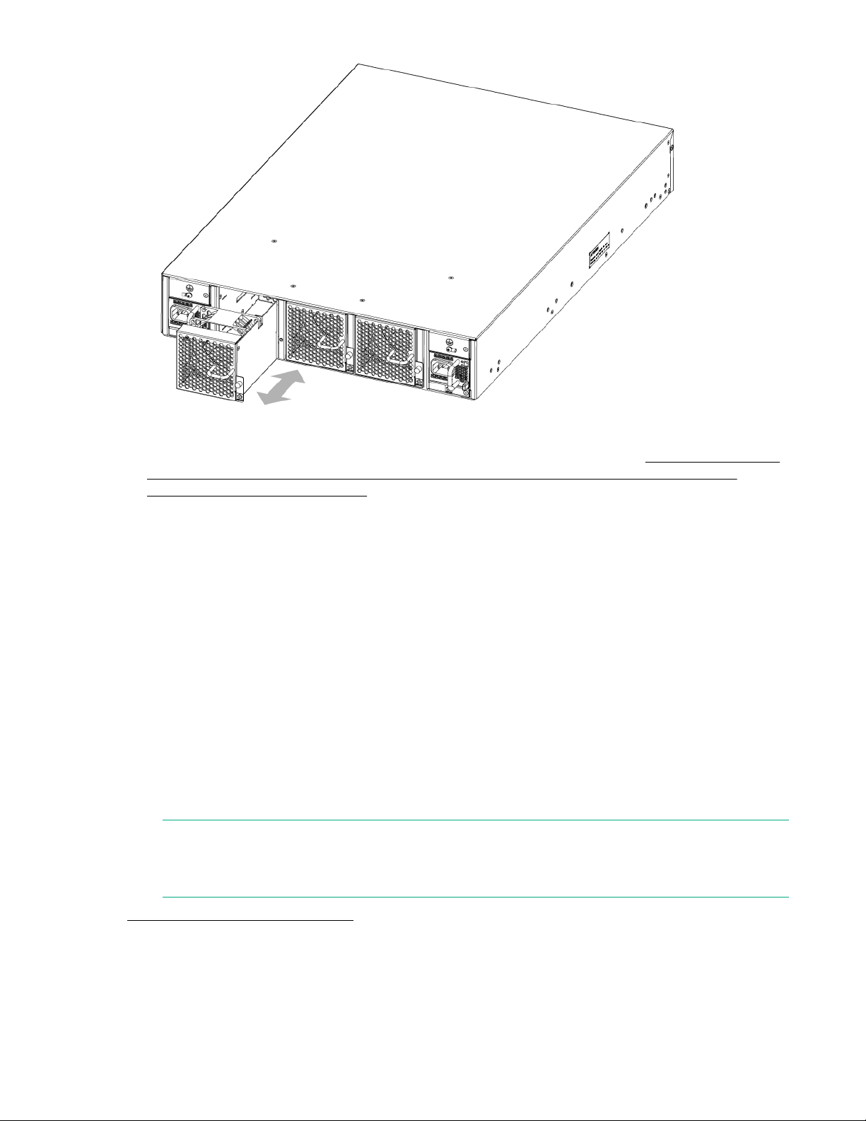
Figure 44: Inserting the fan in the HPE StoreFabric SN6500B 16Gb FC Switch or the HPE StoreFabric SN4000B SAN Extension Switch
4. Verify that the fan status LED is steady green to indicate normal operation. See LED patterns on the
nonport side of the HPE StoreFabric SN6500B 16Gb FC Switch and the HPE StoreFabric
SN4000B SAN Extension Switch for more information.
Optionally, using the CLI, enter the fanShow command or chassisShow command to display the
power supply status.
You can also use Web Tools to view the fan status.
Replacing the HPE SN6000B or SN3000B 16Gb FC Switch power supply and fan assembly
The fans are fixed inside the combined power supply and fan FRU to provide the airflow needed to cool
the switch. Each FRU contains two fans. The system software measures and sets fan speed through the
tachometer interface.
The SN3000B switch comes with one power supply and fan assembly. Fabric OS identifies the
assemblies from right to left on the nonport side. Even though they are contained within a single unit, the
power supply and fan components are identified separately. In the chassisShow command they are
identified as Power Supply Unit:1 and Fan Unit:1.
The SN6000B switch has two power supply and fan assemblies. The two power supply and fan
assemblies are hot-swappable if replaced one at a time. They are identical and fit into either slot.
NOTE:
When replacing the power supply and fan assembly in an SN3000B 16Gb FC Switch that has only
one, the switch must be powered off prior to replacing the assembly.
Power supply and fan assemblies shows the power supply and fan assemblies on the nonport side of a
switch with two assemblies. The standard SN3000B 16Gb FC Switch includes a single power supply and
fan assembly. Fabric OS identifies the assemblies from right to left as assemblies 1 and 2. (The actual
appearance of the switch may differ slightly from this illustration, but the locations are correct.)
Replacing the HPE SN6000B or SN3000B 16Gb FC Switch power supply and fan assembly 71
Page 72

1 2
1. Power supply and fan assembly #2 2. Power supply and fan assembly #1
Figure 45: Power supply and fan assemblies
Determining the status of a power supply and fan assembly
Use one of the following methods to determine the status of the power supply and fan assembly:
• Check the power supply and fan assembly status LED next to the AC power switch (see
supply/fan assembly status LEDs on the nonport side of the HPE SN6000B and SN3000B 16Gb
FC switches ).
• In Web Tools, click the Power Status icon.
• Enter the psshow command at the prompt to display the power supply and fan assembly status:
br6510:admin> psshow
Power Supply #1 is OK
Power Supply #2 is OK
br6510:admin>
Removing a power supply and fan assembly
The following items are required:
• New power supply and fan assembly
• #1 Phillips screwdriver
To remove a power supply and fan assembly (Replacing the power supply and fan assembly):
Procedure
1. If the switch is rack mounted, remove the plenum.
2. If the switch has two power supply and fan assemblies, go to step 3. When replacing the power supply
and fan assembly in an SN3000B 16Gb FC Switch that has only one assembly, the switch must be
powered off before removing the assembly.
Enter the sysShutDown command before powering off the assembly to maintain the reliability of the
system.
Power
NOTE:
To keep the switch in service when replacing a power supply and fan in a switch with two
assemblies, verify that the other assembly has been powered on for at least four seconds and
that its LED is steady green.
3. Power off the power supply to be replaced by setting the AC power switch to the off (O) position.
The fans in the other power supply automatically switch to high speed to maintain adequate cooling.
4. Unplug the power cord from the power supply and fan assembly being replaced.
5. Unscrew the captive screw using a Phillips screwdriver.
72 Determining the status of a power supply and fan assembly
Page 73
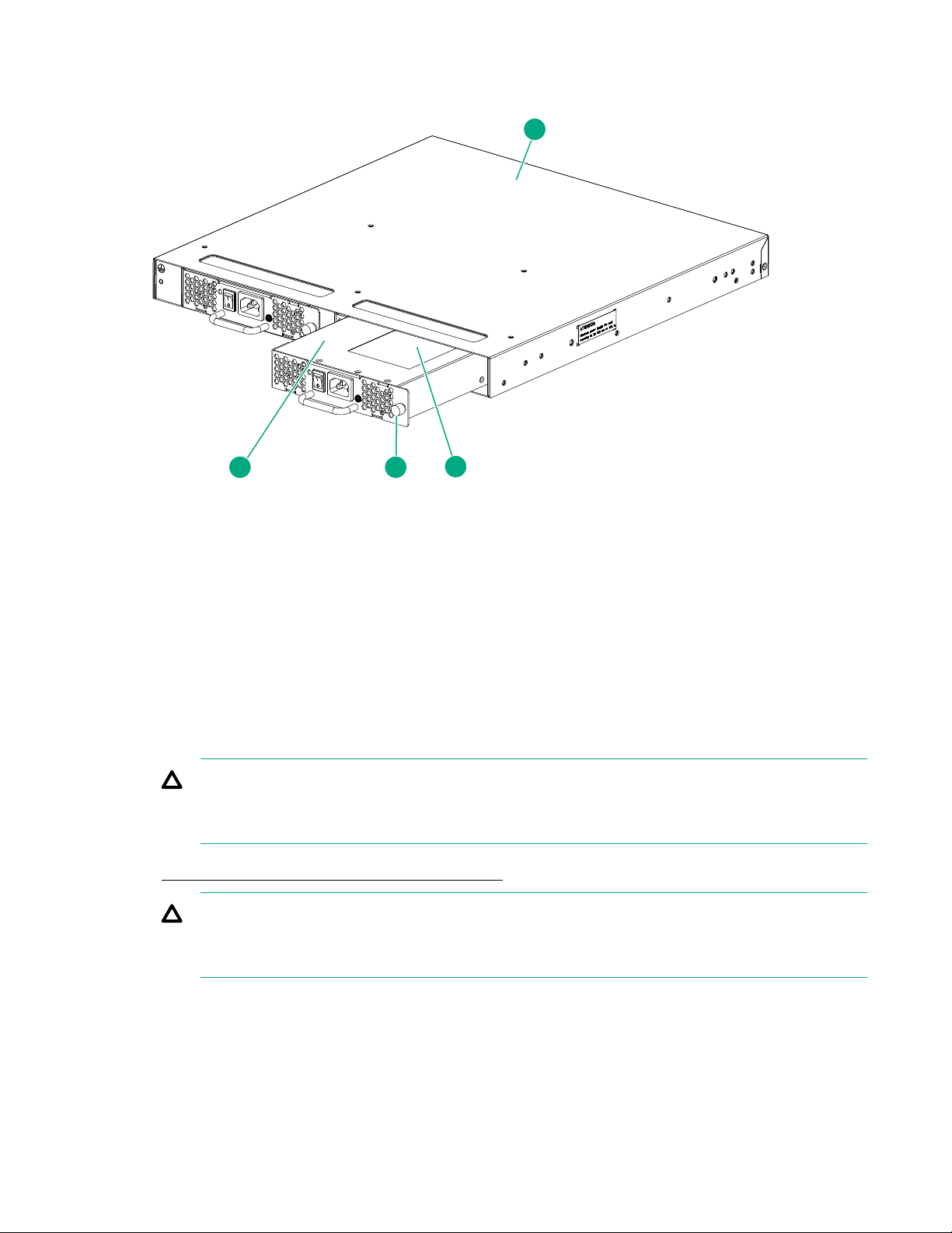
6. Remove the power supply and fan assembly by pulling the handle out and away from the chassis.
1
2 3
4
7. Note the product and airflow labels (or their absence) on the assembly just removed.
Figure 46: Replacing the power supply and fan assembly
1. Switch chassis 2. Power supply and fan assembly
3. Captive screw 4. Product and airflow labels
Installing a power supply and fan assembly
To install the power supply and fan assembly:
Procedure
1. Ensure that the replacement FRU AC power switch is in the off (O) position.
CAUTION:
Damage to the switch can result if the AC power switch is in the on (|) position when the switch is
installed in the chassis.
2. Orient the new power supply and fan assembly with the captive screw on the right, as shown in
Replacing the power supply and fan assembly.
CAUTION:
Do not force the assembly into the chassis. If it does not slide in easily, ensure that it is oriented
correctly before continuing.
3. Gently push the power supply and fan assembly into the chassis until it is firmly seated.
4. Using the Phillips screwdriver, secure the power supply and fan assembly to the chassis by tightening
the captive screw.
5. Plug the power cord into the power supply and fan assembly and power on the unit by setting the AC
power switch to the on (I) position.
Installing a power supply and fan assembly 73
Page 74

6. Verify that the LED on the new power supply and fan assembly displays a steady green light while the
switch is operating. If the LED is not a steady green, ensure that the power supply is installed securely
and seated properly.
7. If the switch is installed in a rack, replace the plenum.
8. Optional: If you are using the CLI, enter the psshow command at the command-line prompt to display
the status. Power supply and fan assembly status can also be viewed using Web Tools.
74 Operating HPE 16Gb FC switches
Page 75

Support and other resources
Accessing Hewlett Packard Enterprise Support
• For live assistance, go to the Contact Hewlett Packard Enterprise Worldwide website:
www.hpe.com/assistance
• To access documentation and support services, go to the Hewlett Packard Enterprise Support Center
website:
www.hpe.com/support/hpesc
Information to collect
• Technical support registration number (if applicable)
• Product name, model or version, and serial number
• Operating system name and version
• Firmware version
• Error messages
• Product-specific reports and logs
• Add-on products or components
• Third-party products or components
Accessing updates
• Some software products provide a mechanism for accessing software updates through the product
interface. Review your product documentation to identify the recommended software update method.
• To download product updates, go to either of the following:
◦ Hewlett Packard Enterprise Support Center Get connected with updates page:
www.hpe.com/support/e-updates
◦ Software Depot website:
www.hpe.com/support/softwaredepot
• To view and update your entitlements, and to link your contracts and warranties with your profile, go to
the Hewlett Packard Enterprise Support Center More Information on Access to Support Materials
page:
www.hpe.com/support/AccessToSupportMaterials
Websites
Website Link
IMPORTANT:
Access to some updates might require product entitlement when accessed through the Hewlett
Packard Enterprise Support Center. You must have an HP Passport set up with relevant
entitlements.
Hewlett Packard Enterprise Information Library
Hewlett Packard Enterprise Support Center
www.hpe.com/info/enterprise/docs
www.hpe.com/support/hpesc
Table Continued
Support and other resources 75
Page 76

Website Link
Contact Hewlett Packard Enterprise Worldwide
Subscription Service/Support Alerts
Software Depot
Customer Self Repair
Insight Remote Support
Serviceguard Solutions for HP-UX
Single Point of Connectivity Knowledge (SPOCK)
Storage compatibility matrix
Storage white papers and analyst reports
Customer self repair
Hewlett Packard Enterprise customer self repair (CSR) programs allow you to repair your product. If a
CSR part needs to be replaced, it will be shipped directly to you so that you can install it at your
convenience. Some parts do not qualify for CSR. Your Hewlett Packard Enterprise authorized service
provider will determine whether a repair can be accomplished by CSR.
www.hpe.com/assistance
www.hpe.com/support/e-updates
www.hpe.com/support/softwaredepot
www.hpe.com/support/selfrepair
www.hpe.com/info/insightremotesupport/docs
www.hpe.com/info/hpux-serviceguard-docs
www.hpe.com/storage/spock
www.hpe.com/storage/whitepapers
For more information about CSR, contact your local service provider or go to the CSR website:
www.hpe.com/support/selfrepair.
Remote support
Remote support is available with supported devices as part of your warranty or contractual support
agreement. It provides intelligent event diagnosis, and automatic, secure submission of hardware event
notifications to Hewlett Packard Enterprise, which will initiate a fast and accurate resolution based on your
product’s service level. Hewlett Packard Enterprise strongly recommends that you register your device for
remote support.
For more information and device support details, go to the following website:
www.hpe.com/info/insightremotesupport/docs
Documentation feedback
Hewlett Packard Enterprise is committed to providing documentation that meets your needs. To help us
improve the documentation, send any errors, suggestions, or comments to Documentation Feedback
([email protected]). When submitting your feedback, include the document title, part number,
edition, and publication date located on the front cover of the document. For online help content, include
the product name, product version, help edition, and publication date located on the legal notices page.
76 Customer self repair
Page 77

Specifications
This appendix provides switch specifications.
Physical specifications
Table 12: HPE StoreFabric SN6500B 16Gb FC Switch physical specifications
Dimension Value
Height 86.74 mm (3.415 in)
Depth 609.75 mm (24.006 in)
Width 429.25 mm (16.900 in)
Weight (with two power supplies and three fan
assemblies, and no transceivers installed)
16.9 kg (37.3 lb)
Table 13: HPE SN6000B and SN3000B 16Gb FC switches physical specifications
Dimension Value
Height 1U or 4.3 cm (1.7 in)
Depth (without plenum) 44.3 cm (17.4 in)
Width (The slightly increased width requires a slim
rail rack mount kit for mounting.)
Weight (with two power supply and fan assemblies,
and no SFPs installed)
Weight (with one power supply and fan assembly,
and no SFPs installed)
43.8 cm (17.2 in)
9.2 kg (20.2 lb)
7.82 kg (17.25 lb)
Table 14: StoreFabric SN4000B SAN Extension Switch physical specifications
Dimension Value
Height 8.6 cm (3.39 in)
Depth 60.9 cm (24.0 in)
Width 44 cm (17.32 in)
Weight (with all the fans and PSU FRUs) 18.23 kg (40.2 lb)
Specifications 77
Page 78

Facility requirements
Table 15: Facility requirements
Dimension Value
Electrical • Adequate supply circuit, line fusing, and wire size, as specified by the
Thermal • Minimum airflow of 79.8 cubic m/hr (47 cubic ft/min) available in the
electrical rating on the switch nameplate
• Circuit protected by a circuit breaker and grounded in accordance
with local electrical codes
See HPE StoreFabric SN6500B 16Gb FC Switch power supply
specifications for complete power supply specifications.
immediate vicinity of the switch
• Ambient air temperature not exceeding 40°C (104°F) while the
switch is operating
Cabinet (rack mounted)
Use rack kits designed for the
extra width of the switch to
mount in standard cabinets/
racks.
• 1U in a 48.3 cm (19 in) cabinet
• All equipment in cabinet grounded through a reliable branch circuit
connection
• Plenum installed to prevent overheating
• Additional weight of switch not to exceed the cabinet’s weight limits
• Cabinet secured to ensure stability in case of unexpected movement
Power supply specifications
The power supplies are universal and operate worldwide without voltage jumpers or switches. They meet
IEC 61000-4-5 surge voltage requirements and support autoranging to accommodate input voltages and
line frequencies. Each power supply has built-in fans for cooling.
Table 16: HPE StoreFabric SN6500B 16Gb FC Switch power supply specifications
Specification Values
Input voltage Range: 90–264 VAC Auto-volt, Nominal: 100–240 VAC, 12.0-5.0 A;
47-63 Hz
The switch autosenses input voltage
Startup: 80–87 VAC; Turn-off: 85–75 VAC
Input frequency Range: 47–63 Hz; Nominal: 50–60 Hz
Inrush current Maximum of 40 A peak at 240 VAC during cold startup at 25ºC
Input line protection Both AC lines are fused
Maximum power supply output
(each)
78 Facility requirements
ambient
1,080 W at 12 VDC
Page 79

Table 17: SN6000B 16Gb FC Switch power supply specifications
Specification Values
Input voltage Range: 85–264 VAC Auto-volt, Nominal: 100–240 VAC, 2.0 A, 47–
63 Hz; the switch autosenses input voltage
Input frequency Range: 47–63 Hz; Nominal: 50–60 Hz
Inrush current Maximum of 50 A peak at 240 VAC for any initial current surge or
spike of 10 ms or less at cold startup. Additional inrush current
surges or spikes in the form of AC cycles, or multiple AC cycles
greater than 10 ms and less than 150 ms, must not exceed 15 A
peak.
Single power supply output 150 W at 12 VDC
Maximum current 12.5 A at 12 VDC
Input line protection Both AC lines are fused
System power consumption 110 W with all 48 ports populated with 16 Gb/s SWL optical media
72 W with empty chassis and no optical media
Table 18: SN3000B 16Gb FC Switch power supply specifications
Specification Values
Input voltage Range: 85–264 VAC, nominal: 100–240 VAC
Input frequency Range: 47–63 Hz; Nominal: 50–60 Hz
Inrush current Maximum of 35 A peak at 240 VAC for 10 ms or less
Single power supply output 150 W at 12 VDC
Input line protection AC lines are fused
System power consumption 80 W with all 24 ports populated with 16 Gb/s SWL optical media
60 W with empty chassis and no optical media
Specifications 79
Page 80

Table 19: StoreFabric SN4000B SAN Extension Switch power supply
specifications
Specification Values
Input voltage Range: 90–264 VAC, Nominal: 100–240 VAC, 50–60 Hz. 200–240
VAC is recommended.
The switch autosenses input voltage.
Input frequency Nominal: 50–60 Hz
Inrush current Maximum of 40 A peak at any initial current surge at cold or warm
start
Maximum input current 12-5 A
Input line protection AC lines are fused
Maximum output power rating
1
(DC)
1
The SN4000B SAN Extension Switch does not support DC power supply.
1100 W
Environmental requirements
HPE SN6000B and SN3000B 16Gb FC switches environmental requirements lists the acceptable
environmental ranges for both operating and nonoperating (such as during transportation or storage)
conditions.
Table 20: HPE StoreFabric SN6500B 16Gb FC Switch environmental requirements
Condition Acceptable range during operation Acceptable range during nonoperation
Ambient
temperature
Humidity 10% to 85% RH noncondensing, at 40ºC
Altitude 0 to 3 km (9,842 ft) above sea level 0 to 12 km (39,370 ft) above sea level
Shock 20 G, 6 ms, half-sine wave 33 G, 11 ms, half-sine wave, 3/e.g. Axis
0º to 40ºC (32º to 104ºF) -25º to 70ºC (-13º to 158ºF)
(104ºF)
10% to 90% RH noncondensing, at 70ºC
(158ºF)
Vibration 0.5 G sine, 0.4 gms random, 5–500 Hz 2.0 G sine, 1.1 gms random, 5–500 Hz
Airflow Maximum: 176.7 cubic m/h (104 cubic
ft/m)
Nominal: 52.7 cubic m/h (31 cubic f/m)
Heat
dissipation
80 Environmental requirements
1,378.5 BTU/hr (no optics configuration)
1,706.1 BTU/hr (fully populated port
configuration)
N/A
N/A
Page 81

Table 21: HPE SN6000B and SN3000B 16Gb FC switches environmental
requirements
Condition Acceptable range during operation Acceptable range during nonoperation
Ambient
temperature
Humidity 10% to 85% RH noncondensing, at 40ºC
Altitude 0 to 3 km (9,842 ft) above sea level 0 to 12 km (39,370 ft) above sea level
Shock 20 G, 6 ms, half-sine wave 33 G, 11 ms, half-sine wave, 3/e.g. Axis
Vibration 0.5 G sine, 0.4 gms random, 5–500 Hz 2.0 G sine, 1.1 gms random, 5–500 Hz
Airflow Maximum: 71.36 cubic m/h (42 cubic ft/m)
Heat
dissipation
0º to 40ºC (32º to 104ºF) -25º to 70ºC (-13º to 158ºF)
10% to 90% RH noncondensing, at 70ºC
(104ºF)
Nominal: 59.47 cubic m/h (35 cubic f/m)
338 BTU/hr (32-port configuration)
375 BTU/hr (48-port configuration)
(158ºF)
N/A
N/A
Table 22: StoreFabric SN4000B SAN Extension Switch environmental
requirements
Condition Acceptable range during operation Acceptable range during nonoperation
Ambient
temperature
Humidity 5% to 93% RH noncondensing, at 40ºC
Altitude 0 to 3 km (9,842 ft) above sea level 0 to 12 km (39,370 ft) above sea level
Shock 20 G, 11 ms, half-sine wave 20 G, 11 ms, half-sine wave, 3/e.g. Axis
Vibration 1.0 G sine, 0.5 gms random, 5–500 Hz 2.4 G sine, 1.1 gms random, 5–500 Hz
Airflow Maximum: 347 cubic m/h (204 cubic ft/m) N/A
Operating
noise
0º to 40ºC (32º to 104ºF) -25º to 70ºC (-13º to 158ºF)
10% to 95% RH noncondensing, at 70ºC
(104ºF)
48.0 dBA N/A
(158ºF)
Specifications 81
Page 82

General specifications
Table 23: HPE StoreFabric SN6500B 16Gb FC Switch general specifications
Specification Description
Configurable port types E_Port, F_Port, M_Port, and D_Port; EX_Port with license
System architecture Nonblocking shared-memory switch
System processor PowerPC family CPU at 1.20 GHz
ANSI FC protocol FC-PH
Modes of operation FC Class 2 and Class 3
Fabric initialization Complies with FC-SW-3 Rev. 6.6
FC-IP Complies with FC-IP 2.3 of FCA profile
Aggregate switch I/O bandwidth 1,536 Gb/s end-to-end full duplex
Local port latency 700 ns
Switch latency 2,100 ns (2.1 microseconds) with no Forward Error Correction
Table 24: SN6000B 16Gb FC Switch general specifications
Specification Description
Configurable port types F_Port, E_Port, M_Port, EX_Port, and D_Port
System architecture Nonblocking shared-memory switch
System processor PowerPC 440EPx at 667 MHz
ANSI FC protocol FC-PH
Modes of operation FC Class 2 and Class 3
Fabric initialization Complies with FC-SW-3 Rev. 6.6
FC-IP Complies with FC-IP 2.3 of FCA profile
Aggregate switch I/O bandwidth 768 Gb/s
FC port-to-port latency Less than 700 ns with no contention (destination port is free)
Aggregate switching capacity 420 million frames per second (for Class 2, Class 3, and Class F
82 General specifications
frames for the 48 port chassis)
Page 83

Table 25: SN3000B 16Gb FC Switch general specifications
Specification Description
Configurable port types F_Port, E_Port, M_Port, EX_Port, and D_Port
System architecture Nonblocking shared-memory switch
System processor PowerPC 440EPx at 667 MHz
ANSI FC protocol FC-PH
Modes of operation FC Class 2 and Class 3
Fabric initialization Complies with FC-SW-3 Rev. 6.6
FC-IP Complies with FC-IP 2.3 of FCA profile
Aggregate switch I/O bandwidth 384 Gb/s
FC port-to-port latency 800 ns with no contention (destination port is free)
Aggregate switching capacity An aggregate switching capacity of 210 million frames per second
(for Class 2, Class 3, and Class F frames for the 24 port chassis)
Table 26: StoreFabric SN4000B SAN Extension Switch general specifications
Specification Description
Configurable port types F_Port, E_Port, M_Port, D_Port and Ex_Port
System architecture Nonblocking shared-memory extension switch
System processors Quadcore (P3041) Freescale (PowerPC) processor, 1.5 GHz Cavium
6880 for frame/packet processing
Blitzer for Encryption and Compression (Xilinx Kintex-7)
Condor-3 for FC Trident+ for 10/40 GE
ANSI FC protocol FC-PH
Modes of operation FC Class 2 and Class 3
Fabric initialization Complies with FC-SW-3 Rev. 6.6
FC-IP Complies with FC-IP 2.3 of FCA profile
Aggregate switch I/O bandwidth 384 Gb/s
FC port-to-port latency 700 ns with no contention, cut-through routing at 16 Gb/s
Aggregate switching capacity 425 million frames per sec
Specifications 83
Page 84

Data transmission ranges
Table 27: HPE StoreFabric SN6500B 16Gb FC Switch supported optics, speeds,
cables, and distances (SFP+)
Transceiver
type
SWL 2 Gb/s1150 m (492 ft) 300 m (984
LWL 4 Gb/s N/A N/A N/A N/A 30 km (18.6
Speed Multimode
media (62.5
microns)
(OM1)
4 Gb/s 70 m (229 ft) 150 m (492
8 Gb/s 21 m (68 ft) 50 m (164 ft) 150 m (492 ft) 150 m (492 ft) N/A
10 Gb/s 33 m (108 ft) 82 m (269 ft) 300 m (984 ft) 550 m
16 Gb/s 15 m (49 ft) 35 m (115 ft) 100 m (328 ft) 125 m (410 ft) N/A
8 Gb/s N/A N/A N/A N/A 10 km (6.2 mi)
Multimode
media (50
microns)
(OM2)
ft)
ft)
Multimode
media (50
microns)
(OM3)
500 m (1,640
ft)
380 m (1,264
ft)
Multimode
media (50
microns)
(OM4)
N/A N/A
400 m
(1,312 ft)
(1,804 ft)
Single Mode
Media (9
microns)
N/A
N/A
mi)
40 km (24.8
mi)
10 Gb/s N/A N/A N/A N/A 10 km (6.2 mi)
16 Gb/s N/A N/A N/A N/A 10 km (6.2 mi)
ELWL 16 Gb/s N/A N/A N/A N/A 25 km (15.5
mi)
1
Hewlett Packard Enterprise does not support 2 Gb/s connectivity to the StoreFabric SN6500B 16Gb FC
Switch. HP SN6000B 16Gb FC Switch or the HP SN3000B 16Gb FC Switch.
NOTE:
Up to 7,500 km at 2 Gb/s is supported when using a long-distance transport system such as
DWDM.
84 Data transmission ranges
Page 85

Table 28: HPE SN6000B and SN3000B 16Gb FC switches supported optics,
speeds, cables, and distances (SFP+)
Transceiver
type
SWL 4 Gb/s 70 m (229 ft) 150 m (492
LWL 8 Gb/s N/A N/A N/A N/A 10 km (6.2 mi)
ELWL 4 Gb/s N/A N/A N/A N/A 30 km (18.6
Speed Multimode
media(62.5
microns)
(OM1)
8 Gb/s 21 m (68 ft) 50 m (164 ft) 150 m (492 ft) 190 m (623 ft) N/A
10 Gb/s 33 m (108 ft) 82 m (269 ft) 300 m (984 ft) 550 m (1,804
16 Gb/s 15 m (49 ft) 35 m (115 ft) 100 m (328 ft) 125 m (410 ft) N/A
10 Gb/s N/A N/A N/A N/A 10 km (6.2 mi)
16 Gb/s N/A N/A N/A N/A 10 km (6.2 mi)
Multimode
media (50
microns)
(OM2)
ft)
Multimode
media (50
microns)
(OM3)
380 m (1,264
ft)
Multimode
media (50
microns)
(OM4)
400 m (1,312
ft)
ft)
Single Mode
Media (9
microns)
N/A
N/A
mi)
8 Gb/s N/A N/A N/A N/A 25 km (15.5
mi)
Table 29: StoreFabric SN4000B SAN Extension Switch supported optics, speeds,
cables, and distances (SFP+)
Speed Cable size
(microns)
2 Gb/s
1
4 Gb/s 50 150 m (492 ft) (OM2)
50 300 m (984 ft) (OM2)
62.5 150 m (492 ft) N/A N/A
9 N/A 10 km (6.2 mi) 80 km (50 mi)
62.5 70 m (230 ft) N/A N/A
SWL LWL ELWL
N/A N/A
500 m (1,640 ft)
(OM3)
N/A N/A
380 m (1,246 ft)
(OM3)
Table Continued
Specifications 85
Page 86

Speed Cable size
(microns)
9 N/A 10 km (6.2 mi) N/A
SWL LWL ELWL
8 Gb/s 50 50 m (164 ft) (OM2)
N/A N/A
150 m (492 ft) (OM3)
62.5 21 m (69 ft) N/A N/A
9 N/A 10 km (6.2 mi) N/A
16 Gb/s 50 N/A N/A N/A
62.5 21 m (69 ft) N/A N/A
9 N/A 10 km (6.2 mi) N/A
1
Hewlett Packard Enterprise does not support 2 Gb/s connectivity to the StoreFabric SN4000B SAN
Extension Switch.
For Fibre Channel ports, the SN4000B Fibre Channel ports support the following SFP/SFP+ fiber optic
transceivers:
• 16G SWL SFP+
• 16G LWL 10km SFP+
• 16G ELWL 25km SFP+
• 10G FC SWL SFP+
• 10G FC LWL 10km SFP+
• 8G SWL SFP+
• 8G LWL 10km SFP+
• 8G ELWL 25km SFP+
• SmartOptics 16G DWDM 40km SFP+ (not in CSD, 3rd party reference sell)
• SmartOptics 8G DWDM 40km SFP+ (not in CSD, 3rd party reference sell)
• SmartOptics 8G CWDM 70km SFP+ (not in CSD, 3rd party reference sell)
For Ethernet user data ports, the following SFP/SFP+ fiber optic and copper transceivers are supported:
1/10GbE ports
• 1GE copper SFP (XBR-000190)
• 1GE SX SFP
• 1GE LX 10km SFP
• 1GE CWDM 80km SFP+
• 10GE USR SFP+ (100m)
• 10GE SR SFP+ (300m)
• 10GE LR SFP+ (10km)
• 10GE Tunable DWDM 80km SFP+
40GbE ports
• 40GE SR4 QSFP+; standard, non-breakout capable
• 40GE LR4 10km QSFP+; standard, non-breakout capable
86 Specifications
Page 87
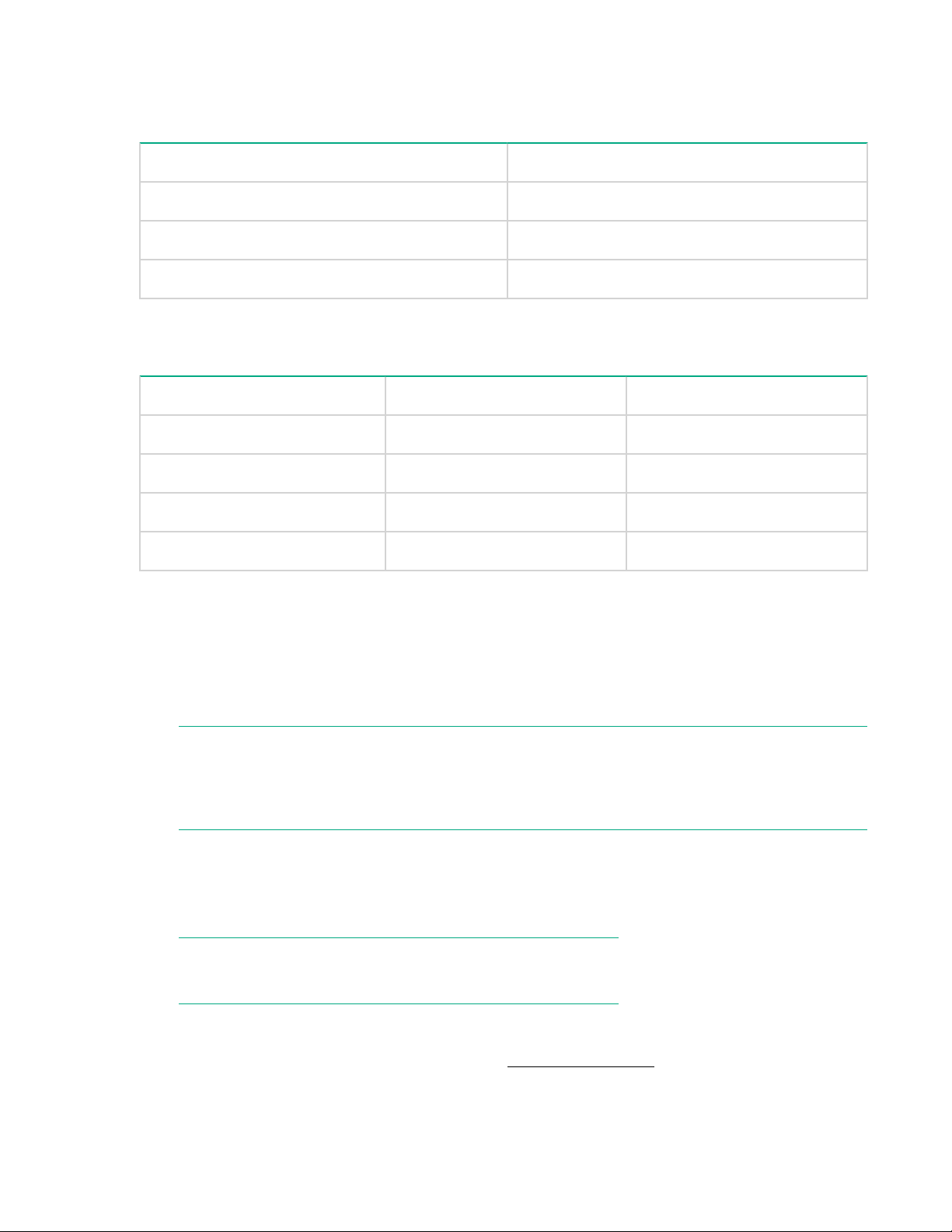
Memory specifications
Table 30: Memory specifications
Memory type Size
Boot flash 4 MB (expandable to 8 MB)
Compact flash 1 GB
Main memory (DDR2 SDRAM) 1 GB, 64-bit with 8-bit ECC
Table 31: Memory specifications for the StoreFabric SN4000B SAN Extension
Switch
Memory type Memory type Size
Boot Flash 4 MB (expandable to 8 MB)
Compact flash USB 8 GB
Control plane DDR3 RDIMM SDRAM 8 GB
Data plane DDR3 RDIMM SDRAM 128 GB
FC port specifications
The FC ports are compatible with SWL, LWL, and ELWL SFP+ (for 16 Gb/s performance) transceivers.
The strength of the signal is determined by the type of transceiver in use.
The FC ports meet all required safety standards. The ports operate at 2, 4, 8, or 16 Gb/s, depending on
SFP+ models, and are able to autonegotiate to the maximum link speed.
NOTE:
Hewlett Packard Enterprise does not support 2 Gb/s connectivity to the StoreFabric SN6500B 16Gb
FC Switch, SN6000B 16Gb FC Switch, SN3000B 16Gb FC Switch, or StoreFabric SN4000B SAN
Extension Switch.
Serial port specifications
The serial port is located on the port-side of the switch and uses an RJ-45 connector for the serial port.
An RJ-45 to DB9 adapter cable is supplied with the switch.
NOTE:
To prevent damage, keep the cover on the port when not in use.
Before connecting the switch to a fabric or IP network, you must connect to a workstation through the
serial port and configure the switch IP address. The serial port’s parameters are fixed at 9600 baud, 8
data bits, and no parity, with flow control set to None. Serial cable pinouts lists the serial cable pinouts.
Memory specifications 87
Page 88

Table 32: Serial cable pinouts
Pin Signal Description
1 Not supported N/A
2 Not supported N/A
3 UART1_TXD Transmit data
4 GND Logic ground
5 GND Logic ground
6 UART1_RXD Receive data
7 Not supported N/A
8 Not supported N/A
AG default port mapping
SN6000B 16Gb FC Switch AG default port mapping lists the port mappings of F_Ports to N_Ports.
Table 33: SN6000B 16Gb FC Switch AG default port mapping
Total ports F_Ports N_Ports Default port mapping
48 0–39 40–47 0–4 mapped to 40
5–9 mapped to 41
10–14 mapped to 42
15–19 mapped to 43
20–24 mapped to 44
25–29 mapped to 45
30–34 mapped to 46
35–39 mapped to 47
88 AG default port mapping
Page 89

Table 34: SN3000B 16Gb FC Switch AG default port mapping
Total ports F_Ports N_Ports Default port mapping
24 0–15 16–23 0, 1 mapped to 16
2, 3 mapped to 17
4, 5 mapped to 18
6, 7 mapped to 19
8, 9 mapped to 20
10, 11 mapped to 21
12, 13 mapped to 22
14, 15 mapped to 23
Specifications 89
Page 90

Warranty and regulatory information
For important safety, environmental, and regulatory information, see Safety and Compliance Information
for Server, Storage, Power, Networking, and Rack Products, available at
Compliance-EnterpriseProducts.
Warranty information
HPE ProLiant and x86 Servers and Options
www.hpe.com/support/ProLiantServers-Warranties
HPE Enterprise Servers
www.hpe.com/support/EnterpriseServers-Warranties
HPE Storage Products
www.hpe.com/support/Storage-Warranties
HPE Networking Products
www.hpe.com/support/Networking-Warranties
Regulatory information
www.hpe.com/support/Safety-
Belarus Kazakhstan Russia marking
Manufacturer and Local Representative Information
Manufacturer information:
• Hewlett Packard Enterprise Company, 3000 Hanover Street, Palo Alto, CA 94304 U.S.
Local representative information Russian:
• Russia:
• Belarus:
• Kazakhstan:
90 Warranty and regulatory information
Page 91
Local representative information Kazakh:
• Russia:
• Belarus:
• Kazakhstan:
Manufacturing date:
The manufacturing date is defined by the serial number.
CCSYWWZZZZ (serial number format for this product)
Valid date formats include:
• YWW, where Y indicates the year counting from within each new decade, with 2000 as the starting
point; for example, 238: 2 for 2002 and 38 for the week of September 9. In addition, 2010 is indicated
by 0, 2011 by 1, 2012 by 2, 2013 by 3, and so forth.
• YYWW, where YY indicates the year, using a base year of 2000; for example, 0238: 02 for 2002 and
38 for the week of September 9.
Turkey RoHS material content declaration
Ukraine RoHS material content declaration
Turkey RoHS material content declaration 91
Page 92

Electrostatic discharge and grounding recommendations
Electrostatic discharge recommendations
CAUTION:
To prevent damaging the system, be aware of the precautions you need to follow when setting up
the system or handling parts. A discharge of static electricity from a finger or other conductor may
damage system boards or other static-sensitive devices. This type of damage can reduce the life
expectancy of the device.
To prevent electrostatic damage, observe the following precautions:
• Avoid hand contact by transporting and storing products in static-safe containers.
• Keep electrostatic-sensitive parts in their containers until they arrive at static-free workstations.
• Place parts on a grounded surface before removing them from their containers.
• Avoid touching pins, leads, or circuitry.
• Always make sure you are properly grounded when touching a static-sensitive component or
assembly.
Grounding methods
There are several methods for grounding. Use one or more of the following methods when handling or
installing electrostatic sensitive parts:
• Use a wrist strap connected by a ground cord to a grounded workstation or computer chassis. Wrist
straps are flexible straps with a minimum of 1 megohm ± 10 percent resistance in the ground cords. To
provide proper ground, wear the strap snug against the skin.
• Use heel straps, toe straps, or boot straps at standing workstations. Wear the straps on both feet
when standing on conductive floors or dissipating floor mats.
• Use conductive field service tools.
• Use a portable field service kit with a folding static-dissipating work mat. If you do not have any of the
suggested equipment for proper grounding, have an Hewlett Packard Enterprise authorized reseller
install the part.
NOTE:
For more information on static electricity, or for assistance with product installation, contact your
Hewlett Packard Enterprise authorized reseller.
92 Electrostatic discharge and grounding recommendations
Page 93

Glossary
This glossary defines acronyms and terms used in this Guide or related to this product. It is not a
comprehensive glossary of computer terms.
AD
Admin Domain.
AG
Access Gateway.
APM
Advanced Performance Monitoring.
ARL
Adaptive Rate Limiting.
CUP
Control Unit Port.
D_Port
Diagnostic port.
DDR2
Double data rate 2.
DHCP
Dynamic Host Configuration Protocol.
DPOD
Dynamic Ports on Demand.
DPS
Dynamic Path Selection.
DWDM
Dense wavelength-division multiplexing.
ECC
Error-correcting code.
ELWL
Extended Long Wavelength.
FC
Fibre Channel.
FCIP
Fibre Channel over Internet Protocol.
Glossary 93
Page 94

FC-PH
Fibre Channel Physical and Signaling Interface.
FCR
Fibre Channel Routing.
FCS
Fabric Configuration Server.
FICON
Fibre Connection or Fibre Connectivity.
FRU
Field replaceable unit.
FTP
File Transfer Protocol.
GMT
Greenwich Mean Time.
HBA
Host Bus Adapter.
HCL
Hot Code Load.
IOPS
Input and Output Operations Per Second.
ISL
Inter-Switch Link.
LC
Lucent connector.
LTU
License To Use.
LWL
Long Wavelength.
M_Port
Mirror port.
NPIV
N_Port ID Virtualization.
NTP
Network Time Protocol server.
OM3
Optical Multimode 3.
94 Glossary
Page 95

PN
Part Number.
POD
Ports on Demand.
POST
Power-on self-test
QoS
Quality of Service.
RAS
Reliability, Availability, and Serviceability.
RISC
Reduced Instruction Set Computer.
RTC
Real-time Clock.
SAN
Storage Area Network.
SCP
Secure Copy.
SDRAM
Synchronous Dynamic Random-Access Memory.
SEEPROM
Serial Electrically Erasable Programmable Read Only Memory.
SFP
Small Form-Factor Pluggable.
SNMP
Simple Network Management Protocol.
SWL
Short Wavelength.
UTC
Coordinated Universal Time.
VF
Virtual Fabric.
WWN
World Wide Name.
Glossary 95
 Loading...