

Page 1

SDCAB-0603 (PEZ)
User Guide
Part number: xxxxxx-xxx
First edition: MM/YYYY
Page 2

Legal notices
Never leverage legal and notice information. For the most current requirements, refer to HP Standard 004-0 Legal Notices for
Product Documentation, Promotional Materials, and Software and Media located at
http://standards.inet.cpqcorp.net/smc/hpstd/hpstds.htm
2
Page 3
Page 4

CANADA STATEMENT
Operation is subject to the following two conditions:
(1) this device may not cause interference and
(2) this device must accept any interference, including interference that may cause
undesired operation of the device
To prevent radio interference to the licensed service, this device is intended to be operated
indoors and away from windows to provide maximum shielding.
Note:
This device has been designed to operate with an antenna having a maximum gain of 2 dBi.
Antenna having a higher gain is strictly prohibited per regulations of I ndustry Canada. The
require antenna impedance is 50 ohms.
To reduce potential radio interference to other users, the antenna type and its gain should be
so chosen that the EIRP is not more than required for successful communication.
Page 5

Contents
Revision history
Revision tables..........................................................................................................................................................4
1 Introduction
1-1 Package Contents .......................................................................................................................................5
1-2 Physical Details..............................................................................................................................................6
1-3 LED Table .......................................................................................................................................................7
1-4 Operating System.........................................................................................................................................7
1-5 List of Supported HP Devices ......................................................................................................................7
2 Physical Installation
2-1 Procedure...........................................................................................................................................................8
3 Software Installation
3-1 Installation Procedure.......................................................................................................................................9
3-2 WPS icon in the System Tray...........................................................................................................................12
3-3 Managing Print Jobs .......................................................................................................................................12
3-4 Using the HP Dire ct or.......................................................................................................................................12
4 Advanced Application
4-1 Overview...........................................................................................................................................................14
4-2 Advanced Configuration...............................................................................................................................14
4-3 User Installation ................................................................................................................................................18
4-3 WPS icon in the System Tray...........................................................................................................................21
5 Troubleshooting
5-1 Overview...........................................................................................................................................................22
5-2 General Pr oblems............................................................................................................................................22
6 Specification
6-1 WPS Specification............................................................................................................................................23
6-2 Wireless Dongle Specification........................................................................................................................23
Appendix A
Index
Contents 3
Page 6

Revision history
Revision tables
Table 1 Revisions
Date Edition Revision
March 27, 2006 First Original Readme.doc released by Sercomm
Revision history
4 錯誤! 尚未定義樣式。
Page 7
1 Introduction
Congratulations on the purchase of your WPS. Your WPS was designed to provide a simple and
efficient network printing and multi-function sol ution.
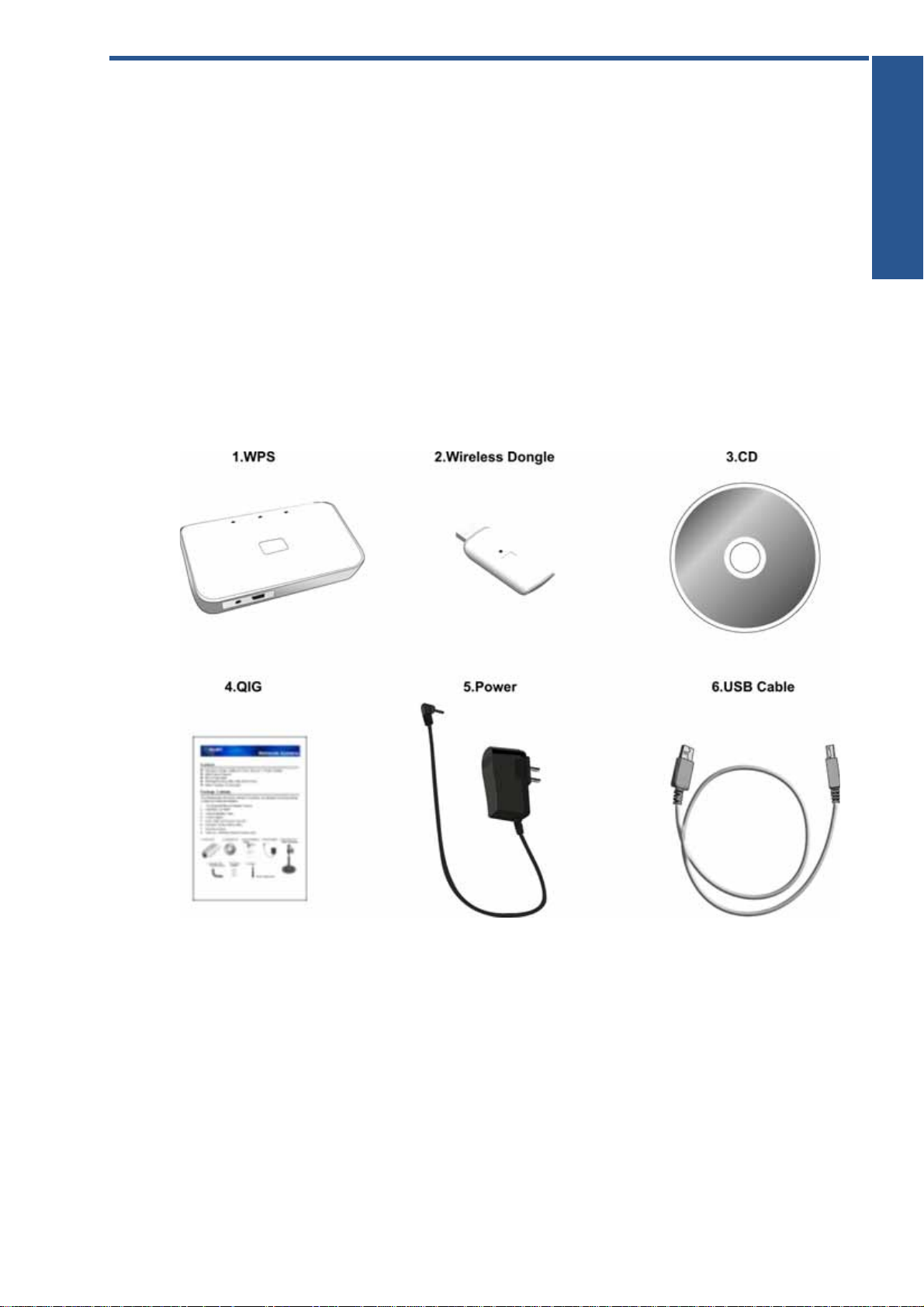
1-1 Package Contents
The WPS package contains the following items. If any item is missing, please contact your dealer
immediately.
• The WPS unit
• The Wireless Dongle unit
• One CD-ROM containing all support programs and this manual
• Quick installation guide
• Power Adapter (3.3V, 2A)
• USB Cable
Figure 1-1
Introduction
錯誤! 尚未定義樣式。 5
Page 8

1-2 Physical Details
• WPS
Figure 1-2
• Wireless Dongle
Figure 1-3
6 錯誤! 尚未定義樣式。
Page 9

1-3 LED Table
There are three (3) LED indicators on the top panel - Power (Green), 802.11G (Blue) and Attention
(Amber). The following table describes common situations and explains what the lights mean.
Table 1-1 LED Table
POWER (GREEN) 802.11G (BLUE) ATTENTION (Amber)
Power Off Off Off Off
Power On On Off Off
Device initialized On On Off
Data Transmission On Blinking Off
No MFP connected to USB
Port
FW Upgrade (data
transmission)
FW Upgrade (write to Flash) Blinking Off Off
On On/Blinking On
On Blinking Off
1-4 Operating System
The following operating systems are supported:
Introduction
• Windows XP Home/Professional Stock
• Windows XP Home/Professional SP2
• Windows XP Home/Professional SP1
• Windows 2000 Professional SP4
1-5 List of Supported HP Devices
HP AiOs for Home and Home Office:
PSC 1210, 1350, 1410, 1507, 1315, 1510, 1600, 1610, 2110, 2175, 2210, 2355, 2410, 2510.
Photosmart 2575, 2610, 3210, 2710, 3310.
Officejet 4110, 4125, 5110, 5510, 5610, 6110, 6210, 7210, 7310, 7410.
Photo printers:
Photosmart 145, 230, 245, 325, 375, 7260, 7350, 7550, 7660, 7850, 7960, 8050, 8250, 335, 385, 422, 475,
425, 428.
Deskjet printers:
Deskjet 3425, 3450, 3520, 3550, 3650, 3745, 3820, 3930, 3940, 3845, 5150, 5550, 5740, 5850, 6540, 6840,
9650, 9670.
錯誤! 尚未定義樣式。 7
Page 10

2 Physical Installation
2-1 Procedure
Figure 2-1
1. Make sure the WPS and MFP (Multi-Function Peripheral) are powered OFF.
2. Connect the MFP to the USB port on the WPS.
3. Connect the Power Adapter to the WPS Power port, power on the M FP.
4. Power on the WPS.
5. Check the WPS LEDs:
• The Power LED should be ON.
• The 802.11g LED should be ON.
• The Attention LED should be Off.
6. Begin Software installation.
8 錯誤! 尚未定義樣式。
Page 11

3 Software Installation
3-1 Installation Procedure
Step 1. Insert the Setup Wizard CD-ROM into your CD-ROM drive. The Setup Wizard should run
automatically, and the Welcome screen should appear. If it does not start automatically, click the
Start button on your computer and choose Run. In the field that appears, enter D:\autorun.exe (if “D”
is the letter of your CD-ROM drive).
Figure
Software Installation
Step 2. Click Install to install the necessary drivers.
Figure
Step 3. Select I accept the terms in the license agreement, then click Next.
錯誤! 尚未定義樣式。 9
Page 12

Figure
Software Installation
Step 5. Connect Wireless Dongle to your PC. After detecting the Dongle unit, this screen will be closed
and you are ready to move to the next step.
Figure
Step 6. This screen indicates that wizard is copyi ng necessary files into your hard drive.
NOTE: If the following screen appears, please make sure the com ponents on this screen are
activated.
10 錯誤! 尚未定義樣式。
Page 13

Figure
Step 7. Click Connect and Finish.
Installation is now complete.
Figure
Now, please insert the WPS CD-ROM to install the software.
錯誤! 尚未定義樣式。 11
Page 14

3-2 WPS icon in the System Tray
When the installation is complete, the WPS icon will appear on the system tray. You are now ready to
use the MFP.
Figure
NOTE: You can right click the WPS icon and select About to get more information of the WPS
connection. See the following sample screen:
Software Installation
3-3 Managing Print Jobs
Print jobs can be managed in the same way as any Windows printer. Opening the Printers folder (Start
- Settings – Printers and Faxes), you will notice that the HP device (ex. Wireless HP Officejet 7300 series)
had been set for the default printer. You can double-click the printer to check current printing jobs.
3-4 Using the HP Director
The HP Director is installed on your computer when you install the HP software. You can do more with
your HP MFP by using the HP Director software. This software provides enhanced copy, scan, and
photo functionality. For more information, see the onscreen HP Direct Help.
1. Open the HP Director from the desktop icon or the start menu.
Figure
2. Select the HP device (ex. Wireless HP Officejet 7300 series) from the drop-down list.
3. Choose the desired feature to use.
12 錯誤! 尚未定義樣式。
Page 15

IMPORTANT: You can click the Status menu to check the connection of the HP device. The status
should always be connected.
錯誤! 尚未定義樣式。 13
Page 16

4 Advanced Application
4-1 Overview
You can also share your MFP with other computers over an existing network. The computer directly
connected to the Wireless Dongle has access to all of the MF P’s features. You can then use the
Access Point to link your Wireless Stations to your wired LAN. The Wireless stations and devices on th e
wired LAN are then on the same network. The other computers, which on the same network can use
all the features of MFP as well.
Advanced application will help you to establish multi-solutions shared by users in your wired LAN.
NOTE: You still need to connect the Wireless Dongle with your PC to take advantage of the
advanced configuration.
Figure
4-2 Advanced Configuration
Step 1. Select Start – Programs – Wireless Printer Adapter
Step 2. Click Advanced Setup
Figure
Step 3. On the screen shown above, select Yes or No as required.
14 錯誤! 尚未定義樣式。
Page 17

Step 4. Select the desired Access Point.
Figure
Step 5. Click Next to move to the Security Setting screen.
Figure
Advanced Application
• SSID - All Wireless stations MUST use the same SSID/ESSID to communicate with one another.
• Security – There are 5 options for Wireless security:
• Disabled - no data encryption is used.
• WEP (64 – Bit) - data is encrypted using the Wired Equivalent Privacy (WEP) 64-bit (weak
security) standard.
• WEP (128 – Bit) - data is encrypted using the WEP 128-bit (a little better security) standard.
• WPA-PSK - data is encrypted using the Wi-Fi Protected Access with Preshared Key standard.
Introduced in 2003, WPA is wireless security with far greater protection than WEP. WPA-PSK
offers two encryption methods, TKIP and AES, with dynamic encryption keys.
• WPA2-PSK – WPA2 is a stronger version of WPA.
錯誤! 尚未定義樣式。 15
Page 18

Figure
• Passphrase – Enter a Passphrase, also called a pre-shared key, of 8 to 63 characters. The longer
and more complex your Passphrase, the more secure your network will be.
• Network Key – Enter the Network key in this field.
• Confirm Network Key – Re-enter the Network key here.
Figure
• Data Encryption – Sel ec t the desired option. Other Wireless Stations must use the same method.
• Network Key – Enter the Network key in this field.
• Confirm Network Key – Re-enter the Network key here.
16 錯誤! 尚未定義樣式。
Page 19

Step 6. The IP Address Setting screen will be displayed.
Figure
• Select Obtain IP Address automatically if your LAN has a DHCP Server, otherwise select Use
following IP address.
• If you click Use the following IP address, enter an unused address from the address pools used in
your LAN.
Use the same IP Subnet Mask and Default Gateway in your LAN.
Step 7. The Confirmation screen will appear. After rev i ewing the settings, click Apply to save them.
Figure
錯誤! 尚未定義樣式。 17
Page 20

Step 8. The following Successful screen is displayed next.
Figure
Step 9. Click Finish to exit the Wizard.
4-3 User Installation
Step 1. Insert the Setup Wizard CD-ROM into your CD-ROM drive.
Figure
Step 2. Click Install to install the necessary drivers.
18 錯誤! 尚未定義樣式。
Page 21

Figure
Step 3. Select I accept the terms in the license agreement, then click Next.
Figure
Step 4. The wizard is checking the connection. After checking, this screen will be closed and you are
ready to move to the next step.
錯誤! 尚未定義樣式。 19
Page 22

Figure
Step 4. Select the desired Print Server. Click Next.
Figure
Step 5. Wizard is copying necessary files into your hard drive.
20 錯誤! 尚未定義樣式。
Page 23

Figure
Step 5. Click Connect and Finish.
Installation is now complete.
4-3 WPS icon in the System Tray
Software Installation
When the installation is complete, the WPS icon will appear on the system tr ay. The WPS will be
connected automatically if the MFP is currentl y not being used. If the MFP is occupied by other user,
you need to connect the WPS manually after the job is done. Right click the WPS icon in the system
tray and choose Connect as needed.
Figure
錯誤! 尚未定義樣式。 21
Page 24

5 Troubleshooting
5-1 Overview
This chapter contains the troubleshooting i nform ation for the WPS. If, after following the advice in
these documents, the WPS still does not function properly, please contact your dealer for further
advice.
5-2 General Problems
If, after several attempts to connect with the WPS, the icon in the system tray still indicates a “nogood” status.
Solution
• Make sure there is no other station user occupying the WPS. When you move cursor to the
WPS icon, there should be a “No Connection” message.
• Check to see if the wireless connection between your PC and the WPS is working. Ping
192.168.173.1 from command mode. The WPS should respond to ping request from your
Dongle.
• Make sure the printer’s USB cable is connected to the WPS and the printer is powered on.
Troubleshooting
22 錯誤! 尚未定義樣式。
Page 25

6 Specification
6-1 WPS Specification
Table 6-1 WPS
Power Consumption
External Power Adapter 3.3V DC, 2A
LEDs 3
USB Port 1
FCC / CE FCC, CE. Class B
6-2 Wireless Dongle Specification
Table 6-2 Wireless Dongle
Power Consumption PC Bus Power
LED 1
USB Port USB Device
FCC / CE
錯誤! 尚未定義樣式。 23
Page 26

Appendix A
Appendix A
24 錯誤! 尚未定義樣式。
Page 27

Index
錯誤! 尚未定義樣式。 25
 Loading...