

Page 1

HP Ultrium tape drives
Technical reference manual
Generation 3 drives
Volume 3—the SCSI interface
Part Number: Q15 30–90901 Volume 3
Edition 6, December 2004
Page 2

Legal and notice information
© Copyrigh t 2000–2004—Hewlett-Packard Development Company, L.P.
The information contained in this document is subject to change without notice.
Hewlett-Packard makes no warranty of any kind with regard to this material, including, but not limited to, the implied warranties of
merchantab ility and fitness for a parti c u l ar purp ose. Hewlett -Packard shall not be liable for errors contained herein or direct,
indirect, special, incidental or consequential damages in connection with the furnishing, performance, or use of this document.
This document contains proprietary information which is protected by copyright. All rights reserved. No part of this document may
be photocopied, reproduced or translated to another language without the prior written consent of Hewlett-Packard.
Revision history
Version Date Changes
Edition 1 Nov. 2000 All
Edition 2 Mar. 2001 Addition of Read and Write attribute commands and Drive Error Codes
Edition 3 May 2002 Inclusion of the Request Block Address command and the Control mode page, together
with numerous small changes
Edition 5 July 2003 Many small changes
Edition 6 December 2004 Generation 3 version
This document is frequently revised and updated. To find out if there is a later version, please ask your HP OEM Representative.
Page 3

Contents
Related documents . . . . . . . . . . . . . . . . . . . . . . . . . . . . . . . . . . . . . . . . . . . . . . . . . . . . . . 7
Documents specific to HP Ultrium drives . . . . . . . . . . . . . . . . . . . . . . . . . . . . . . . . . . . 7
Documentation map . . . . . . . . . . . . . . . . . . . . . . . . . . . . . . . . . . . . . . . . . . . . . . . . 7
General documents and standardization . . . . . . . . . . . . . . . . . . . . . . . . . . . . . . . . . 10
1 Interface Implementation
The SCSI interface . . . . . . . . . . . . . . . . . . . . . . . . . . . . . . . . . . . . . . . . . . . . . . . . . . . . . 11
Supported messages . . . . . . . . . . . . . . . . . . . . . . . . . . . . . . . . . . . . . . . . . . . . . . . . . 11
Supported commands. . . . . . . . . . . . . . . . . . . . . . . . . . . . . . . . . . . . . . . . . . . . . . . . . 12
SCSI features . . . . . . . . . . . . . . . . . . . . . . . . . . . . . . . . . . . . . . . . . . . . . . . . . . . . . . . . . 13
Design approach. . . . . . . . . . . . . . . . . . . . . . . . . . . . . . . . . . . . . . . . . . . . . . . . . . . . 13
Power-on . . . . . . . . . . . . . . . . . . . . . . . . . . . . . . . . . . . . . . . . . . . . . . . . . . . . . . . . . 13
Reset strategy . . . . . . . . . . . . . . . . . . . . . . . . . . . . . . . . . . . . . . . . . . . . . . . . . . . . . . 13
Abort handling . . . . . . . . . . . . . . . . . . . . . . . . . . . . . . . . . . . . . . . . . . . . . . . . . . . . . 14
LUN identification
Bus parity or CRC errors. . . . . . . . . . . . . . . . . . . . . . . . . . . . . . . . . . . . . . . . . . . . . . . 15
Disconnect strategy . . . . . . . . . . . . . . . . . . . . . . . . . . . . . . . . . . . . . . . . . . . . . . . . . . 16
Multi-initiator support . . . . . . . . . . . . . . . . . . . . . . . . . . . . . . . . . . . . . . . . . . . . . . . . . 17
Fibre Channel operation . . . . . . . . . . . . . . . . . . . . . . . . . . . . . . . . . . . . . . . . . . . . . . . . . 18
Fibre Channel addressing. . . . . . . . . . . . . . . . . . . . . . . . . . . . . . . . . . . . . . . . . . . . . . 18
Field replaceable units . . . . . . . . . . . . . . . . . . . . . . . . . . . . . . . . . . . . . . . . . . . . . . . . . . 20
CD-ROM emulation. . . . . . . . . . . . . . . . . . . . . . . . . . . . . . . . . . . . . . . . . . . . . . . . . . . . . 21
(parallel SCS I only). . . . . . . . . . . . . . . . . . . . . . . . . . . . . . . . . . . . . . . 15
Contents
2Messages
Message Out support. . . . . . . . . . . . . . . . . . . . . . . . . . . . . . . . . . . . . . . . . . . . . . . . . 23
Message In support . . . . . . . . . . . . . . . . . . . . . . . . . . . . . . . . . . . . . . . . . . . . . . . . . . 24
Extended Message support . . . . . . . . . . . . . . . . . . . . . . . . . . . . . . . . . . . . . . . . . . 25
Status . . . . . . . . . . . . . . . . . . . . . . . . . . . . . . . . . . . . . . . . . . . . . . . . . . . . . . . . . . . . . . 26
3 Commands—introduction
Summary. . . . . . . . . . . . . . . . . . . . . . . . . . . . . . . . . . . . . . . . . . . . . . . . . . . . . . . . . . . . 29
Command details . . . . . . . . . . . . . . . . . . . . . . . . . . . . . . . . . . . . . . . . . . . . . . . . . . . . . . 29
Pre-execution checks. . . . . . . . . . . . . . . . . . . . . . . . . . . . . . . . . . . . . . . . . . . . . . . . . . . . 30
Bad LUN check . . . . . . . . . . . . . . . . . . . . . . . . . . . . . . . . . . . . . . . . . . . . . . . . . . . . . 30
Deferred Error check . . . . . . . . . . . . . . . . . . . . . . . . . . . . . . . . . . . . . . . . . . . . . . . . . 30
Diagnostic Status check . . . . . . . . . . . . . . . . . . . . . . . . . . . . . . . . . . . . . . . . . . . . . . . 31
Fixed Bit check . . . . . . . . . . . . . . . . . . . . . . . . . . . . . . . . . . . . . . . . . . . . . . . . . . . . . 31
Flag Link check . . . . . . . . . . . . . . . . . . . . . . . . . . . . . . . . . . . . . . . . . . . . . . . . . . . . . 31
Contents
3
Page 4

Illegal Command check . . . . . . . . . . . . . . . . . . . . . . . . . . . . . . . . . . . . . . . . . . . . . . . . 31
Illegal Field/Request check. . . . . . . . . . . . . . . . . . . . . . . . . . . . . . . . . . . . . . . . . . . . . . 31
Media Access check . . . . . . . . . . . . . . . . . . . . . . . . . . . . . . . . . . . . . . . . . . . . . . . . . . 32
Media Information check . . . . . . . . . . . . . . . . . . . . . . . . . . . . . . . . . . . . . . . . . . . . . . . 33
Media Write check . . . . . . . . . . . . . . . . . . . . . . . . . . . . . . . . . . . . . . . . . . . . . . . . . . . 33
Parameter List check. . . . . . . . . . . . . . . . . . . . . . . . . . . . . . . . . . . . . . . . . . . . . . . . . . . 34
Reservation check . . . . . . . . . . . . . . . . . . . . . . . . . . . . . . . . . . . . . . . . . . . . . . . . . . . . 34
Unit Attention check. . . . . . . . . . . . . . . . . . . . . . . . . . . . . . . . . . . . . . . . . . . . . . . . . . . 34
Command descriptor block . . . . . . . . . . . . . . . . . . . . . . . . . . . . . . . . . . . . . . . . . . . . . . . . 35
4Commands
ERASE . . . . . . . . . . . . . . . . . . . . . . . . . . . . . . . . . . . . . . . . . . . . . . . . . . . . . . . . . . 19h 38
INQUIRY. . . . . . . . . . . . . . . . . . . . . . . . . . . . . . . . . . . . . . . . . . . . . . . . . . . . . . . . . 12h 39
INQUIRY data pages. . . . . . . . . . . . . . . . . . . . . . . . . . . . . . . . . . . . . . . . . . . . . . . . . . 40
Vital Product Data pages . . . . . . . . . . . . . . . . . . . . . . . . . . . . . . . . . . . . . . . . . . . . . . . 44
Supported Vital Product Data Pages page . . . . . . . . . . . . . . . . . . . . . . . . . . . . . . . . . 44
Unit Serial Number page 45
Device Identification page . . . . . . . . . . . . . . . . . . . . . . . . . . . . . . . . . . . . . . . . . . . . 45
Defined identifiers. . . . . . . . . . . . . . . . . . . . . . . . . . . . . . . . . . . . . . . . . . . . . . . . . . 46
Extended INQUIRY Data VPD page . . . . . . . . . . . . . . . . . . . . . . . . . . . . . . . . . . . . . 48
Sequential Access Device Capabilities page . . . . . . . . . . . . . . . . . . . . . . . . . . . . . . . 48
Drive Component Revision Levels pages . . . . . . . . . . . . . . . . . . . . . . . . . . . . . . . . . . 49
LOAD/UNLOAD . . . . . . . . . . . . . . . . . . . . . . . . . . . . . . . . . . . . . . . . . . . . . . . . . . . 1Bh 50
LOCATE . . . . . . . . . . . . . . . . . . . . . . . . . . . . . . . . . . . . . . . . . . . . . . . . . . . . . . . . . 2Bh 53
LOG SELECT . . . . . . . . . . . . . . . . . . . . . . . . . . . . . . . . . . . . . . . . . . . . . . . . . . . . . . 4Ch 55
LOG SENSE . . . . . . . . . . . . . . . . . . . . . . . . . . . . . . . . . . . . . . . . . . . . . . . . . . . . . . 4Dh 57
Log page format . . . . . . . . . . . . . . . . . . . . . . . . . . . . . . . . . . . . . . . . . . . . . . . . . . . . . 58
Supported Log Pages page. . . . . . . . . . . . . . . . . . . . . . . . . . . . . . . . . . . . . . . . . . . . . . 59
Write Error Counters log page . . . . . . . . . . . . . . . . . . . . . . . . . . . . . . . . . . . . . . . . . . . 60
Read Error Counters log page. . . . . . . . . . . . . . . . . . . . . . . . . . . . . . . . . . . . . . . . . . . . 60
Sequential Access Device log page . . . . . . . . . . . . . . . . . . . . . . . . . . . . . . . . . . . . . . . . 61
Temperature log page . . . . . . . . . . . . . . . . . . . . . . . . . . . . . . . . . . . . . . . . . . . . . . . . . 62
DTD Status log page . . . . . . . . . . . . . . . . . . . . . . . . . . . . . . . . . . . . . . . . . . . . . . . . . . 62
Very High Frequency Data (VHF) . . . . . . . . . . . . . . . . . . . . . . . . . . . . . . . . . . . . . . . 63
Very High Frequency Polling Delay. . . . . . . . . . . . . . . . . . . . . . . . . . . . . . . . . . . . . . 64
DTD Primary Port Status. . . . . . . . . . . . . . . . . . . . . . . . . . . . . . . . . . . . . . . . . . . . . . 64
TapeAlert log page . . . . . . . . . . . . . . . . . . . . . . . . . . . . . . . . . . . . . . . . . . . . . . . . . . . 65
Tape Usage log page . . . . . . . . . . . . . . . . . . . . . . . . . . . . . . . . . . . . . . . . . . . . . . . . . 67
Tape Capacity log page. . . . . . . . . . . . . . . . . . . . . . . . . . . . . . . . . . . . . . . . . . . . . . . . 68
Data Compression log page. . . . . . . . . . . . . . . . . . . . . . . . . . . . . . . . . . . . . . . . . . . . . 68
Performance Data log page . . . . . . . . . . . . . . . . . . . . . . . . . . . . . . . . . . . . . . . . . . . . . 69
Device Status log page. . . . . . . . . . . . . . . . . . . . . . . . . . . . . . . . . . . . . . . . . . . . . . . . . 70
MODE SELECT . . . . . . . . . . . . . . . . . . . . . . . . . . . . . . . . . . . . . . . . . . . . . . . . 15h/55h 71
Mode parameter pages . . . . . . . . . . . . . . . . . . . . . . . . . . . . . . . . . . . . . . . . . . . . . . . . 72
Mode page representation. . . . . . . . . . . . . . . . . . . . . . . . . . . . . . . . . . . . . . . . . . . . 73
Mode data format. . . . . . . . . . . . . . . . . . . . . . . . . . . . . . . . . . . . . . . . . . . . . . . . . . 73
Mode block descriptor . . . . . . . . . . . . . . . . . . . . . . . . . . . . . . . . . . . . . . . . . . . . . . . . . 76
4Contents
Page 5

Read-Write Error Recovery mode page. . . . . . . . . . . . . . . . . . . . . . . . . . . . . . . . . . . . . 76
Disconnect-Reconnect page. . . . . . . . . . . . . . . . . . . . . . . . . . . . . . . . . . . . . . . . . . . . . 78
SCSI drives . . . . . . . . . . . . . . . . . . . . . . . . . . . . . . . . . . . . . . . . . . . . . . . . . . . . . 78
Control mode page . . . . . . . . . . . . . . . . . . . . . . . . . . . . . . . . . . . . . . . . . . . . . . . . . . 79
Data Compression Characteristics page . . . . . . . . . . . . . . . . . . . . . . . . . . . . . . . . . . . . 79
Device Configuration page. . . . . . . . . . . . . . . . . . . . . . . . . . . . . . . . . . . . . . . . . . . . . 81
Medium Partitions mode page. . . . . . . . . . . . . . . . . . . . . . . . . . . . . . . . . . . . . . . . . . . 83
Fibre Channel Logical Unit Control mode page . . . . . . . . . . . . . . . . . . . . . . . . . . . . . . . 84
SCSI LUN Control mode page. . . . . . . . . . . . . . . . . . . . . . . . . . . . . . . . . . . . . . . . . . . 84
Fibre Channel Port Control mode page. . . . . . . . . . . . . . . . . . . . . . . . . . . . . . . . . . . . . 85
SCSI Port Control Mode page. . . . . . . . . . . . . . . . . . . . . . . . . . . . . . . . . . . . . . . . . . . 87
Normal page . . . . . . . . . . . . . . . . . . . . . . . . . . . . . . . . . . . . . . . . . . . . . . . . . . . . 87
Sub-pages . . . . . . . . . . . . . . . . . . . . . . . . . . . . . . . . . . . . . . . . . . . . . . . . . . . . . . 87
Information Exceptions mode page . . . . . . . . . . . . . . . . . . . . . . . . . . . . . . . . . . . . . . . 91
Device Time mode page. . . . . . . . . . . . . . . . . . . . . . . . . . . . . . . . . . . . . . . . . . . . . . . 92
CD-ROM Emulation/Disaster Recovery mode page . . . . . . . . . . . . . . . . . . . . . . . . . . . . 94
MODE SENSE . . . . . . . . . . . . . . . . . . . . . . . . . . . . . . . . . . . . . . . . . . . . . . . . . 1Ah/5Ah 96
PERSISTENT RESERVE IN. . . . . . . . . . . . . . . . . . . . . . . . . . . . . . . . . . . . . . . . . . . . . . 5Eh 98
PERSISTENT RESERVE OUT . . . . . . . . . . . . . . . . . . . . . . . . . . . . . . . . . . . . . . . . . . . 5Fh 101
Additional parameter data. . . . . . . . . . . . . . . . . . . . . . . . . . . . . . . . . . . . . . . . . . 103
PREVENT/ALLOW MEDIUM REMOVAL. . . . . . . . . . . . . . . . . . . . . . . . . . . . . . . . . . . 1Eh 105
READ . . . . . . . . . . . . . . . . . . . . . . . . . . . . . . . . . . . . . . . . . . . . . . . . . . . . . . . . . . 08h 106
READ 6
READ 10
(CD-ROM mode) . . . . . . . . . . . . . . . . . . . . . . . . . . . . . . . . . . . . . . . . . . . . . . 08h 109
(CD-ROM mode) . . . . . . . . . . . . . . . . . . . . . . . . . . . . . . . . . . . . . . . . . . . . . 28h 110
READ ATTRIBUTE . . . . . . . . . . . . . . . . . . . . . . . . . . . . . . . . . . . . . . . . . . . . . . . . . . 8Ch 111
MAM attribute data . . . . . . . . . . . . . . . . . . . . . . . . . . . . . . . . . . . . . . . . . . . . . . . . . 115
Attribute ID values 116
Standard device type attributes. . . . . . . . . . . . . . . . . . . . . . . . . . . . . . . . . . . . . . . 116
Standard medium type attributes. . . . . . . . . . . . . . . . . . . . . . . . . . . . . . . . . . . . . . 118
Standard host type attributes . . . . . . . . . . . . . . . . . . . . . . . . . . . . . . . . . . . . . . . . 118
READ BLOCK LIMITS . . . . . . . . . . . . . . . . . . . . . . . . . . . . . . . . . . . . . . . . . . . . . . . .05h 120
READ BUFFER . . . . . . . . . . . . . . . . . . . . . . . . . . . . . . . . . . . . . . . . . . . . . . . . . . . . 3Ch 121
READ CAPACITY
(CD-ROM mode) . . . . . . . . . . . . . . . . . . . . . . . . . . . . . . . . . . . . . . . 25h 124
Read Capacity data . . . . . . . . . . . . . . . . . . . . . . . . . . . . . . . . . . . . . . . . . . . . . . 124
READ MEDIA SERIAL NUMBER . . . . . . . . . . . . . . . . . . . . . . . . . . . . . . . . . . . . . . . . .ABh 125
READ POSITION . . . . . . . . . . . . . . . . . . . . . . . . . . . . . . . . . . . . . . . . . . . . . . . . . . .34h 127
READ TOC
(CD-ROM mode). . . . . . . . . . . . . . . . . . . . . . . . . . . . . . . . . . . . . . . . . . . . 43h 131
Read TOC data 132
RECEIVE DIAGNOSTICS RESULTS . . . . . . . . . . . . . . . . . . . . . . . . . . . . . . . . . . . . . . 1Ch 133
RELEASE UNIT . . . . . . . . . . . . . . . . . . . . . . . . . . . . . . . . . . . . . . . . . . . . . . . . .1 7h/57h 135
REPORT DENSITY SUPPORT. . . . . . . . . . . . . . . . . . . . . . . . . . . . . . . . . . . . . . . . . . . 44h 137
REPORT DEVICE IDENTIFIER. . . . . . . . . . . . . . . . . . . . . . . . . . . . . . . . . . . . . . . . . . . A3h 140
REPORT LUNS . . . . . . . . . . . . . . . . . . . . . . . . . . . . . . . . . . . . . . . . . . . . . . . . . . . . A0h 141
REPORT SUPPORTED OPCODES . . . . . . . . . . . . . . . . . . . . . . . . . . . . . . . . . . . . . . . A0h 143
REPORT SUPPORTED TASK MANAGEMENT FUNCTIONS . . . . . . . . . . . . . . . . . . . . . A3h 145
REQUEST SENSE . . . . . . . . . . . . . . . . . . . . . . . . . . . . . . . . . . . . . . . . . . . . . . . . . . .03h 147
Request Sense data . . . . . . . . . . . . . . . . . . . . . . . . . . . . . . . . . . . . . . . . . . . . . . . . . 148
Contents
Contents
5
Page 6

Fixed format. . . . . . . . . . . . . . . . . . . . . . . . . . . . . . . . . . . . . . . . . . . . . . . . . . . . . 148
Descriptor format 152
Sense data management . . . . . . . . . . . . . . . . . . . . . . . . . . . . . . . . . . . . . . . . . . . . . . 154
Current sense. . . . . . . . . . . . . . . . . . . . . . . . . . . . . . . . . . . . . . . . . . . . . . . . . . . . 154
UNIT ATTENTION sense . . . . . . . . . . . . . . . . . . . . . . . . . . . . . . . . . . . . . . . . . . . . 155
DEFERRED ERROR sense . . . . . . . . . . . . . . . . . . . . . . . . . . . . . . . . . . . . . . . . . . . . 156
Sense keys . . . . . . . . . . . . . . . . . . . . . . . . . . . . . . . . . . . . . . . . . . . . . . . . . . . . . . . . 157
Additional Sense codes . . . . . . . . . . . . . . . . . . . . . . . . . . . . . . . . . . . . . . . . . . . . . . . 159
Error codes. . . . . . . . . . . . . . . . . . . . . . . . . . . . . . . . . . . . . . . . . . . . . . . . . . . . . . . . 163
RESERVE UNIT . . . . . . . . . . . . . . . . . . . . . . . . . . . . . . . . . . . . . . . . . . . . . . . .16h/56h 164
REWIND . . . . . . . . . . . . . . . . . . . . . . . . . . . . . . . . . . . . . . . . . . . . . . . . . . . . . . . .01h 166
SEEK
(CD-ROM mode). . . . . . . . . . . . . . . . . . . . . . . . . . . . . . . . . . . . . . . . . . . . . . . . 2Bh 167
SEND DIAGNOSTIC . . . . . . . . . . . . . . . . . . . . . . . . . . . . . . . . . . . . . . . . . . . . . . . .1Dh 168
Standard self-test . . . . . . . . . . . . . . . . . . . . . . . . . . . . . . . . . . . . . . . . . . . . . . . . . 169
SET CAPACITY. . . . . . . . . . . . . . . . . . . . . . . . . . . . . . . . . . . . . . . . . . . . . . . . . . . . 0Bh 170
SET DEVICE IDENTIFIER. . . . . . . . . . . . . . . . . . . . . . . . . . . . . . . . . . . . . . . . . . . . . . A4h 171
SPACE . . . . . . . . . . . . . . . . . . . . . . . . . . . . . . . . . . . . . . . . . . . . . . . . . . . . . . . . . .11h 172
START/STOP
TEST UNIT READY . . . . . . . . . . . . . . . . . . . . . . . . . . . . . . . . . . . . . . . . . . . . . . . . . .00h 176
VERIFY . . . . . . . . . . . . . . . . . . . . . . . . . . . . . . . . . . . . . . . . . . . . . . . . . . . . . . . . . .13h 177
WRITE . . . . . . . . . . . . . . . . . . . . . . . . . . . . . . . . . . . . . . . . . . . . . . . . . . . . . . . . . .0Ah 178
WRITE ATTRIBUTE . . . . . . . . . . . . . . . . . . . . . . . . . . . . . . . . . . . . . . . . . . . . . . . . . 8Dh 180
WRITE BUFFER . . . . . . . . . . . . . . . . . . . . . . . . . . . . . . . . . . . . . . . . . . . . . . . . . . . .3Bh 183
WRITE FILEMARKS . . . . . . . . . . . . . . . . . . . . . . . . . . . . . . . . . . . . . . . . . . . . . . . . . .10h 186
(CD-ROM mode) . . . . . . . . . . . . . . . . . . . . . . . . . . . . . . . . . . . . . . . . . . 1Bh 175
Glossary . . . . . . . . . . . . . . . . . . . . . . . . . . . . . . . . . . . . . . . . . .187
Index . . . . . . . . . . . . . . . . . . . . . . . . . . . . . . . . . . . . . . . . . . . .191
6Contents
Page 7

Rel ated documents
This is one of six volumes that document HP Ultrium drives. This volume provides background
information f or dri v er and applicati on dev eloper s. T he follo w ing doc uments pr ov i de additional
information:
Documents specific to HP Ultrium drives
• Hardware Integration Guide, volume 1 of the HP Ultrium Technical Reference Manual
• Software Integration Guide, volume 2 of the HP Ultrium Technical Reference Manual
• Specifications, volume 4 of the HP Ultrium Technical Re f e rence Manual
• HP Ultrium Configuration Guide, volume 5 of the HP Ultrium Technical Reference Manual
• Background to Ultrium Drives, volume 6 of the HP Ultrium Technical Reference Manual
• HP Ultrium Technology White Paper, which describes the features and benefi ts of
HP Ultrium drives
Please contact your HP supplier for copies.
Documentation map
The following will help you locate information in the 6-volume Technical Reference Manual:
Drives—general
l
Connectors 1 HW Integration: ch. 7 1 HW Integr ation: ch. 4
Controller architecture 6 Background: ch. 4
Front Panel LEDs 1 HW Integration: ch. 6 1 HW Integr ation: ch. 3
Mechanism and hardware 6 Background: ch. 3
Specifications 4 Specs
SCSI Drives FC Drives
Installation and configuration
SCSI Drives FC Drives
Connectors 1 HW Integration: ch. 7 1 HW Integration: ch. 4
Determining the configuration 2 SW Integratio n: ch. 2 2 SW Integration: ch. 2
External drives (SCSI only) 1 HW Integration: ch. 5n/a
In Libraries 1 HW Inte gration: ch. 1
In Servers (SCSI only) 1 HW Integration: ch. 4n/a
In Tape Arrays (SCSI only) 1 HW Integration: ch. 3n/a
Modes of Usage (SCSI only) 1 HW Integration: ch. 8n/a
Related documents 7
Page 8

SCSI Drives FC Drives
Optimizing performance (SCSI only) 1 HW Integration: ch. 8n/a
2 SW Integration: ch. 4
UNIX configuration 5 UNIX Config
Operation
SCSI D rives FC Drives
External drives (SCSI only) 1 HW Integration: ch. 5n/a
In Libraries 1 HW Integration: ch. 1
In Servers (SCSI only) 1 HW Integration: ch. 4n/a
In Tape Arrays (SCSI only) 1 HW Integration: ch. 3n/a
Cartridges
SCSI D rives FC Drives
Cartridge Memory (LTO-CM) 2 SW Integration: ch. 5
6 HW Integration: ch. 5
Cartridges 1 HW Integration: ch. 9 1 HW Integration: ch. 5
Features 6 HW Integration: ch. 5
Managing the use of cartridges 2 SW Integration: ch. 1
Use of cartridges 2 SW Integration: ch. 3
Interface
SCSI Drives FC Drives
SCSI Gui de 3 SCSI
Commands 3 SCSI: ch. 4
Error codes 1 HW Integration: ch. 10 1 HW Integration: ch. 6
Implementation 3 SCSI: ch. 1
Interpreting sense data 2 SW Integration: ch. 3
Messages 3 SCSI: ch. 2
Mode pages
—see the MODE SENSE command
Pre-execution checks 3 SCSI: ch. 3
Responding to Sense Keys and ASC/Q 2 SW Integration : ch. 6
Sense Keys and ASC/Q
—see REQUEST SENSE command
8
3 SCSI: ch. 4
3 SCSI: ch. 4
Page 9

Maintenance and troubleshooting
SCSI Drives FC Drives
Cleaning 2 SW Integration: ch. 5
2 SW Integration: ch. 7
External drives (SCSI only) 1 HW Integration: ch. 5n/a
In Libraries 1 HW Inte gration: ch. 1
In Servers (SCSI only) 1 HW Integration: ch. 4n/a
In Tape Arrays (SCSI only) 1 HW Integration: ch. 3n/a
Monitoring drive and tape condition 2 SW Integration: ch. 7
Software troubleshooting techniques 2 SW Integration: ch. 1
Dealing with errors
SCSI Drives FC Drives
Error Codes 1 HW Integration: ch. 10 1 HW Integration: ch. 6
Handling errors 2 SW Int eg rat ion: ch. 5
How error correction works 6 Background: ch. 4
Logs—see the LOG SENSE command 3 SCSI: ch. 4
Recovering from write and read errors 2 SW Integration: ch. 7
Software response to error correction 2 SW Integration: ch. 3
Software response to logs 2 SW Integration: ch. 3
TapeA lert log 2 SW Integration: ch. 7
Ultrium features
SCSI Drives FC Drives
Adaptive Tape Speed (ATS) 6 Background: ch. 1
Autoload 1 HW Inte gration: ch. 2
Automation Control Interface (ACI) 1 HW Inte gration: ch. 2
6 Background: ch. 1
Cartridge Memory (LTO-CM) 1 HW Inte gration: ch. 2
2 SW Integration: ch. 5
6 HW Inte gration: ch. 5
Data Compression, how it works 6 Background: ch. 5
Data Compression, managing 2 SW Integration: ch. 5
Design principles 6 Background: ch. 1
OBDR and CD-ROM emulation 6 Background: ch. 1
2 SW Integration: ch. 7
Performance optimization 1 HW Integration: ch. 8n/a
2 SW Integration: ch. 1
Performance, factors affecting 2 SW Integration: ch. 4
Related documents 9
Page 10

SCSI Drives FC Drives
Software desi gn 2 SW Integration: ch. 1
Supporting Ultrium features 2 SW Integration: ch. 5
Ultrium Format 6 Background: ch. 2
General documents and standardization
• Enhanced Small Computer Sy stem Interface (SCS I- 2), ANSI X3T9.2-1993 Rev. 10L,
available through ANSI
• See http://www.t10.org/t10_main.htm
for ANSI SCSI-3 and other specific ations
Copies of documents of other standards bodies can be obtained from:
ANSI
11 West 42nd Street
New York,
NY 10036-8002
USA
ISO
CP 56
CH-1211 Geneva 20
Switzerland
ECMA
114 Rue du Rhône
Tel: +41 22 849 6000
CH-1204 Geneva
Web URL: http://www.ecma.ch
Tel: 800 854 7179 or 714 261 1455
Global Engineering Documents
Switzerland
2805 McGaw
Irvine, CA 92714
USA
10
Page 11

1 Interface Imp lementation
HP Ultrium drives use SCSI-3 as the interface to connect to the host system.
This chapter gives an overview of how the interface operates.
Full details of the messages are given in Chapter 2 and of commands in Chapter 3 and
Chapter 4.
The SCSI interface
The Small Computer System Interface (SCSI) is an industry standard, approved by the American
National Standards Institute (ANSI). You are recommended to read the ANSI standard document
in conjunction with this manual. The ANSI specification defines the interface in general while this
document describes the HP Ultrium implementation.
The SCSI implementation provides a drive with a standard set of features and functions. These
include the following:
• Synchronous data transfers
• Asynchronous data transfers
• Implementation of all mandatory and most optional commands of the Sequential Access
command set
• LVD (Low-Voltage differential) SCSI connectio n
• Ultra-320 wide SCSI
• Conformance to the following SCSI standards:
• SAM-2 ANSI INCITS .366:2003
• SPI-4 ANSI INCITS.362:2002
•SPC3
• SS C -2 ANSI INCITS.380:2003
Supported messages
The following messages are supported by the drives:
• ABORT
• BUS DEVICE RESET
• COMMAND COMPLETE
Interface Implementation
The SCSI interface
11
Page 12

• DISCONNECT
• IDENTIFY
• IG NORE WIDE RESIDUE
• INITIATOR DETECTED ERROR
• MESSAGE PARI TY E RROR
• MESSAGE REJECT
• NO-OP (no operation)
• PARALLEL PROTOCOL REQUEST (PPR)
• RESTORE POINTERS
• SAVE DATA POINTER
• SYNCHRONOUS DATA TRANSFER REQUEST
• WIDE DATA TRANSFER REQUEST
For implementation details on these messages, see Chapter 2, “Messages”
Supported commands
The following commands are supported by the drives. They include all Mandatory and Extended
commands and most Optional commands.
19h ERASE 03h REQUEST SENSE
12h INQUIRY 44h REPORT DENSITY SUPPORT
1Bh LOAD/UNLOAD A3h (05h) REPORT DEVICE IDENTIFIER
2Bh LOCATE A0h REPOR T LUNS
4Ch LOG SELECT A3h (0Ch) REPORT SUPPORTED OP CODES
4Dh LOG SENSE A3h (0Dh) REPORT SUPPORTED TASK MNGMNT FUNCTNS
15h/55h MODE SELECT 56h/16h RESERVE UNIT
1Ah/5Ah MODE SENSE 01h REWIND
5Eh PERSISTENT RESERVE IN 1Dh SEND DIAGNOSTIC
5Fh PERSISTENT RESERVE OUT 0Bh SET CAPACITY
1Eh PREVENT/ALLOW MEDIUM REMOVAL A4h (06h) SET DEVICE IDENTIFIER
08h READ 11h SPACE
8Ch READ ATTRIBUTE 00h TEST UNIT READY
05h READ BLOCK LIMITS 13h VERIFY
3Ch READ BUFFER 0Ah WRITE
ABh (01h) READ MEDIA SERIAL NUMBER 8Dh WRITE ATTRIBUTE
34h READ POSITION 3Bh WRITE BUFFER
1Ch RECEIVE DIAGNOSTIC RESULTS 10h WRITE FILEMARK S
57h/17h RELEASE UNIT
Interface Implementation12
Page 13

The following additional commands are supported for CD-ROM mode:
08h READ 6 43h READ TOC
28h READ 10 2Bh SEEK
25h READ CAPACITY 1Bh START/STOP UNIT
For implementation details on these commands, see Chapter 3, “Commands—introduction” and
Chapter 4, “Commands”.
SCSI f eatures
Design approach
The features supported b y the dri v e are ba sed on standar ds, both off ici al and de fact o. T he dri ve is
fully compliant with the current SCSI standards: SPC3, SSC2, SAM2, and the relevant transport
protocol (e.g. SPI4 for the parallel SCSI drive). All mandatory commands and features are
supported, as well as some that are optional. In addition, some features from older standards are
still supported for backwards compatibility.
Power-on
The drive will respond to INQUIRY, TEST UNI T READY, REP OR T L UN S and RE QUEST SENSE commands
within 250 ms of power on. The first command received from an initiator (other than
REQUES T SE NSE) w ill r e sult in CHECK CONDITION status, with UNIT ATTENTION sense data reported
for the power on. Once the drive has completed its self-test and set-up procedures, it will attempt
to reload any tape that is already present in the drive. It may take some time to recover the tape,
especially if it wa s po sitioned near EO M when power was cy cl ed . Dur ing ta pe recovery, medium
access commands will result in a sense key of
in process of becoming ready).
Reset strategy
The drive supports reset as follows:
• The current I/O process is aborted
• Any queued I/O processes from other initiators are removed
• All negotiated settings are cleare d
• Mode parameters are cleared to their default values
• Any reservations are cleared (but not persistent reservations)
• Any buffered writes are flushed to tape
• The logical position becomes undefined, unless Rewind-On-Reset has been configured in
which case the drive will rewind to BOM
INQUIRY and
Interface Implementation
NOT READY, with additional sense of 0401h (drive
(parallel SCSI drives only)
SCSI features
13
Page 14

• A UNIT ATTENTION condition is set, based on the type of reset
The drive will respond to
250 ms of the re set line being r elea sed. Th e fir st command f r om any initia tor (other than
REQUEST SENSE and REPORT LUNS) will result in CHECK CONDITION status with UNIT ATTENT ION
sense data for the reset. Note that all commands will receive
completed its internal reset.
The Reset button on the front panel and the ACI_R ESET_L line on the Automation Controller
Interface are both connected to the Power-Up Reset interrupt on the processor. The effect is
equivalent to power-cycling the drive. The contents of the tape and cartridge memory may not be
consistent after the action and any data in the drive buffer will be lost.
Abort handling
If an abort condition is detected before a command phase completes, the bus is set to bus fr ee and
the command is not executed.
If an abort condition is detected between the end of the command phase and the start of the status
phase, the bus is set to bus free and the processing below is carried out.
If an abort condition is detected during status phase, the bus is set to bus free.
If a command (other than
abort but before the drive is ready to process the command, the behavior depends on whether
Disconnects are allowed.
• If disconnects are allo w ed, the dri v e w ill disconnect and w ait un til the abort pr ocessing has
completed before executing the command.
INQUIRY, TEST UNIT READY, REPORT LUNS and REQUEST SENSE within
INQUIRY,
BUSY status until the drive has
INQUIRY for standard data or REQUEST SENSE) is received after the
• If disconnects are not allow e d, a
Command Abort Processing
ERASE Long erase is aborted as quickly as possible without corrupting the tape
format. Short erase completes.
INQUIRY None
LOAD/UNLOAD Load completes and logically positions the tape at BOT.
Unload is aborted leaving the logical position at BO T unless the operation
is past the “point of no return” in which case the tape is eject ed.
LOCATE The logical position is set back to that at the start of the operation.
LOG SELECT If data transfer is complete, the command is completed, otherwise no action
is taken
LOG SENSE None
MODE SELECT If data transfer is complete, the command is completed, otherwise no action
is taken.
MODE SENSE None
Interface Implementation14
BUSY response will be returned.
Page 15

Command Abort Processing
PREVENT/ALLOW
MEDIUM REMOVAL
READ The logical position is set to that at the start of the operation.
READ BLOCK LIMITS None
READ BUFFER None
READ POSITION None
RECEIVE DIAGNOSTICS
RESULTS
RELEASE UNIT The command completes.
REQUEST SENSE Sense data is discarded.
RESERVE UNI T The command completes.
REWIND The command completes.
SEND DIAGNOSTIC If data transfer is complete, the command is completed, otherwise no action
SPACE The logical position is set back to that at the start of the operatio n.
TEST UNIT READY None
WRITE The logical position is set back to that at the start of the operation.
WRITE BUFFER If data transfer is complete, the command is completed, otherwise no action
The command completes.
None
is taken
is taken.
Interface Implementation
WRITE FILEMARKS The logical position is set back to that at the start of the operation
VERIFY The logical position is set back to that at the start of the operation
LUN identification (parallel SCSI only)
Identify messages are used to identify the LUN being addressed by the initiator, and to identify
which LUN is reselecting the initiator. The old LUN field in the CDB from the SCSI-2 standards is
obsolete and should not be used (set to 0).
Bus parity or CRC errors
If the drive detects a bus parity error in a message out or command phase, it will still accept the
command, which will then return
error). Detection of a parity error during the data out phas e also causes the drive to r e turn
CONDITION
. Additional sense is set to 4701h (data phase CRC error detected) if the bus is in DT
mode or 4700h if not.
CHECK CONDITION. Additional sense is 4700h (SCSI parity
SCSI features
CHECK
15
Page 16

If Information Units is enabled (parallel SCSI only), the dri ve will drop the bus on detecting a CRC
error during a LQ_IU. If the CRC error occurs during the Information Units command phase or
data out phase, the driv e will return
4703h (Information Unit CRC error detected).
CHECK CONDITION with a CRC error. Additional sense is set t o
On detecting an Initiator Detected error, the drive will return
sense of 4800h (initator detect ed error message received). The exception is when Information
Units mode is enabled (parallel SCSI only), when one of the following occurs:
• If an IDE message is received dur ing a LQ_IU, the dri ve dr ops the bus and retr ies the LQ_IU
pair.
• If the message is received dur i ng Status IU, the dri ve retries the LQ_Status pair.
• If the message is received during Data IU, the drive sends a LQ_Status with
CONDITION
and additional sense of 4800h.
Disconnect strategy
The disconnect strategy used by the drive is based on maximizing the use of the bus for large
sequential data transfers from a large data buffer. The drive will disconnect whenever it believes
that it will provide better bus use. This may be between command and data phases, between
bursts of data or before sending status. However, the drive will guarantee that it sends the
configured maximum burst size or the remaining data in the transfer in any single data phase
burst if the maximum burst size has been set to a value other than zero.
The following diagram gives an overview of the drive’s disconnect strategy:
CHECK CONDITION with additional
CHECK
Interface Implementation16
Page 17
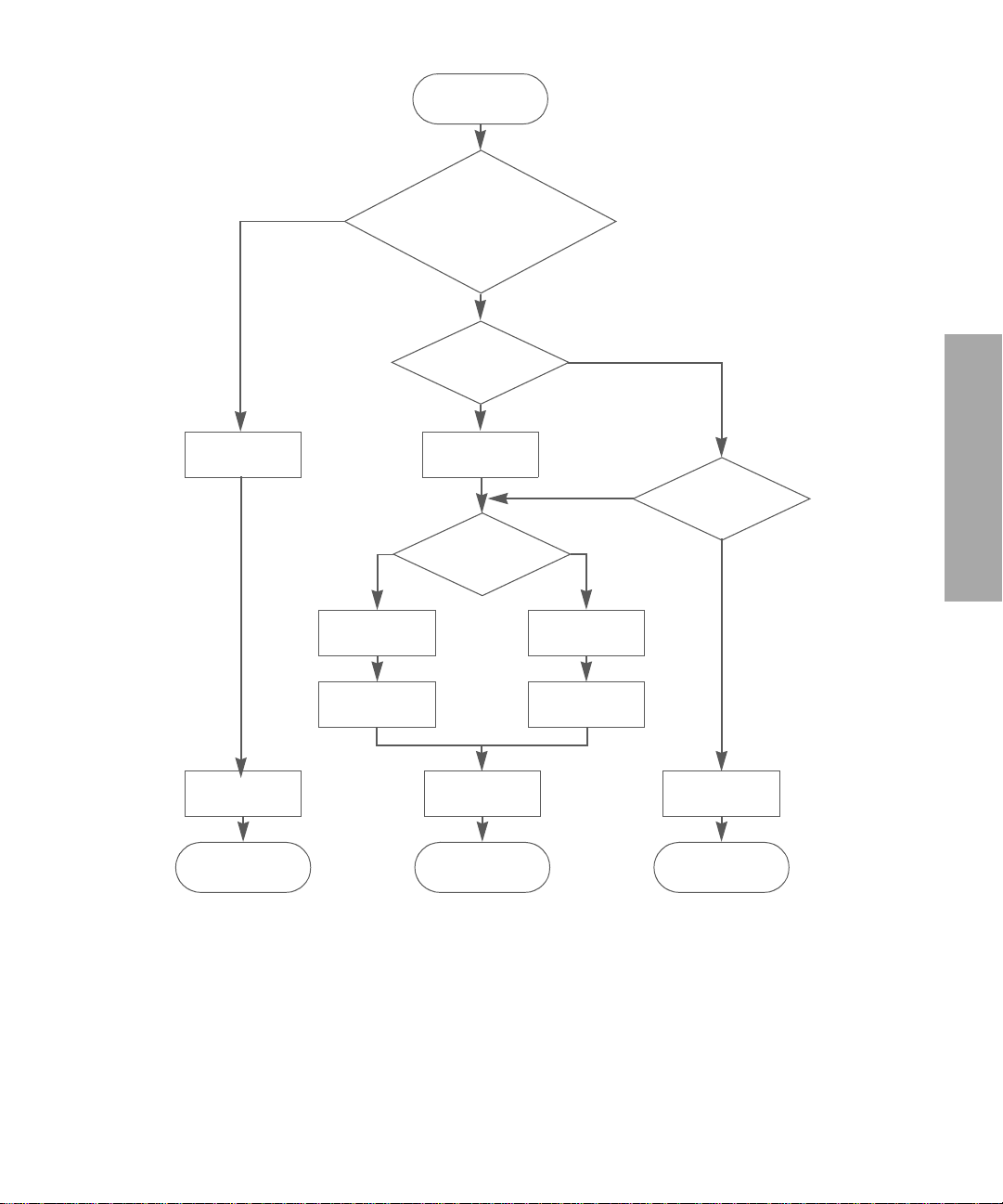
CDB arrives
Yes
REQUEST SENSE from
an initiator in CA or
INQUIR Y w ith EVP D=0
No
Disconnect
priv granted
Yes
DisconnectSend data
No
Reselect
Data transfer
required?
No
No
Yes
ReselectExecu te cmd
Transfer data &
execute c md
Previous cmd
still in progress?
Yes
Interface Implementation
Send status
Cmd complete Cmd comp le te
Multi-initiator support
All drives are design to operate within a multi-initiator environment. The maximum number of
concurrently connected initiators is as follows:
•
Parallel SCSI drives: up to 15 initiators
•
Fibre Channel drives: up to 32 initiators shared across both ports
Send status
Cmd complete
Send BUSY
status
SCSI features
17
Page 18
Sense Data, Unit Attention and Deferred Errors are maintained for each initiator. Mode
Parameters are common to all initiators.
The untagged queuing model implemented by the drives guarantees that all commands are
executed in strict order of receipt. Certain non-media access type commands, such as
READY
, INQUIRY, REQUEST SENS E and REPORT LUNS, are implicitly allowed to queue-jump other
media access type commands, such as
The parallel SCSI drive supports the full command queuing model with a queue depth of 1
(necessary for connectivity purposes). The FC drive supports the basic queuing model with a
queue depth of 4. See “Standard Inquiry Data format (LUN0)” on page 40 for details of the BQue
and CmdQue bits which define this support.
REWIND.
Fibre Channel operation
NOTE: This applies only to Fibr e Channel dr ives.
The following sections have information specific to Fibre Channel operation:
• “Fibre Channel Logical Unit Control mode page” on page 84
• “Fibre Channel Port Control mode page” on page 85
• “Vital Product Data pages” on page 44
TEST UNIT
Fibre Channel addressing
Before describing HP’s implementation of Fibre Channel addressing, the concepts of Names and
Addresses need to be clarified.
Names
Names are 64-bit identifiers assigned permanently to the tape dr iv e during manufactur e. T hey ar e
commonly referred to as World Wide Names since they must be guaranteed unique. The names
are typically used for identifying the device to operating systems, since addresses are assigned
dynamically. There at least eight different name formats distinguished by the Network Address
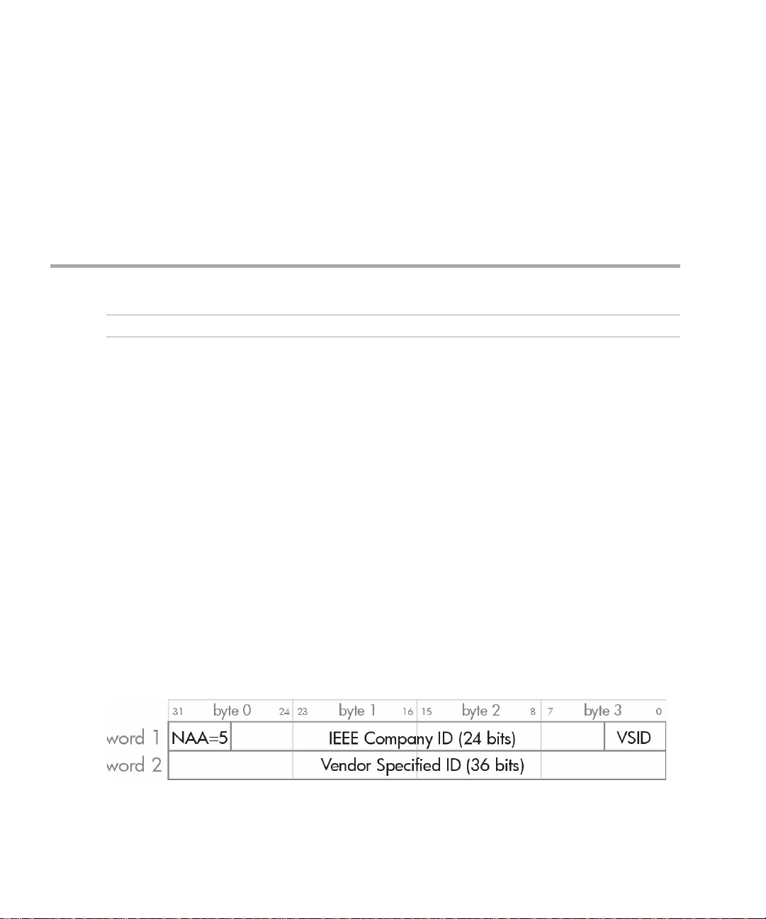
Authority (NAA). Only one is used on HP Ultrium drives. This is the IEEE Registered Name
(NNA=5) and has the following format:
This name is made up of three fields:
• NAA Identifier (4 bits). “5” indicates a IEEE Registered Name.
Interface Implementation18
Page 19
• IEEE Company ID (24 bits). Assigned by IEEE to the company.
• Vendor Specified ID (36 bits). Assigned by the company.
Addresses
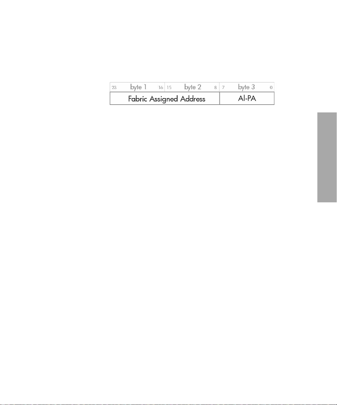
Each Fibre Channel port also has a Port Address which is assigned during loop initialization
and/or Fabric Login. This is a 24-bit value in the following format:
The AL_PA is the Arbitrated Loop Physical Address. This is normally assigned dynamically during
loop initialization.
If the loop is not attached to a fabric (in other words, when it is private,) the top two bytes will be
zero. If the loop is attached to a fabric, the tape drive is assigned the top two bytes when it logs
into the fabric.
Together, the three bytes provide a unique address on the Fibre Channel fabric that is used for
frame addressing. It forms the equivalent of the Target ID or Initiator ID in SCSI.
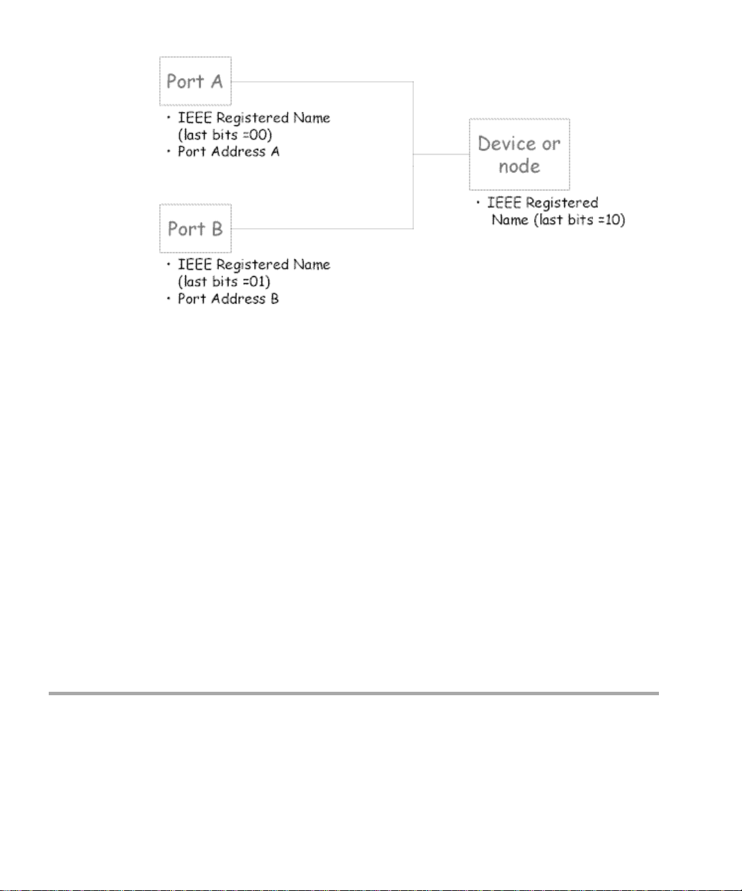
HP’s implementation of names and addresses
The HP implementation uses three adjacent IEEE Registered Names:
• The first (last bits = 00) is used as the Port A World Wide Name.
• The second (last bits = 01) is used as the Port B Wor ld W ide Name.
• The third name (last bits = 10) is used for the Device World Wide Name.
(These are assigned during manufacture from HP’s pool of names, although only the first will
actually be stored in the drive NV-RAM).
The port addresses will be assigned using the ‘standard’ AL_PA initialization mechanisms. The
‘Fibre Channel Port Control mode page’ controls this. The drive has the ability to support hard
addresses as part of this scheme.
Interface Implementation
Fibre Channel operation
19
Page 20
The values of the names can be obtained using the Device Identification Vital Product Information
Page (part of the
INQUIRY command).
Implications for libraries
• Normally a standalone drive will operate using its own ‘hard’ names.
• The drive knows it is in a library or other ‘managed’ environment since one of the signal
lines on the ACI (Automation Control Interface) will be tied dow n.
In this case, the drive will not go on the FC loop until it is told to. The library can optionally
download a new, soft base name (Port A/Device Name) into the drive at this point. The drive
will then use this as the origin of its names. The library manufacturer would be responsible for
obtaining this IEEE Registered Name. It would be a property of the library, not the drive.
• If the library wants to ‘warm swap’ drives, it can. It just ‘tur ns off’ the drive with the soft
name using the ACI and then turns on the spare drive, downloading the same name to it.
• If a drive is removed from the library, it will not have the ACI signal tied low and so will
revert to its original hard name. It should forget the soft name in this case.
• If the library controller breaks , the dri ve w ill time out the A CI interf ace in ~10 seconds. The
drive still knows it is in a library since the ACI signal is still tied low, so in this case it will
use the soft name last downloaded. This will allow drive access without confusing the host.
Field replaceable units
An FRU code identifies which part of the hardware is considered to have failed. These codes turn
up in sense data byte 14 and as the sense code qualifier for sense codes 4400h (internal target
failure) and 40XX (diagnostic failure).
Interface Implementation20
Page 21

Although there are no actual Field Replaceable Units on HP Ultrium drives, the following subassemblies can be replaced at Repair Centres:
• Drive PCA • Head Assembly
• Mechanism • Front Panel
CD-ROM emulation
The One Button Disaster Recovery (OBDR) functionality in HP Ultrium drives enables them to
emulate CD-ROM devices in specific circumstances (also known as being in “Disaster Recovery”
mode). The drive can then act as a boot device for PCs that support booting off CD-ROM.
A CD-ROM capable drive can be switched into CD-ROM mode by powering on with the eject
button held down. The drive then alters its behavior as follows:
• The front panel lights flash a “warbling” sequence.
• CD-ROM commands are executed (as opposed to tape drive mode when they would be
rejected). Commands specific to CD-ROM mode are
CAPACITY
(
LOCATE), these are interpreted as CD-ROM commands 08h (READ 6), 1Bh (ST ART/STOP)
and 2Bh (
. In the case of SCSI commands 08h (READ), 1Bh (LOAD/UNLOAD) and 2Bh
SEEK) respectively.
READ 10, READ TOC and READ
• Writing is disabled.
• Normal
emulation and to sw itch the peripheral device type field to indicate a CD-R O M drive .
• The mode header and mode block descriptor are modified.
• A CD-Emulation mode page is added.
• Mode data changes to reflect CD-ROM medium type and block size.
• Status reporting by the media access check is altered.
• The drive’s sense data when the media is not ready for access always indicates “loading”.
If a tape is inserted while the drive is in CD-ROM mode, the drive assumes that it will contain an
image of a CD offset 20 blocks into the tape. It reads the first 250 kilobytes of this image into
buffer space reserved for CD-caching. It then looks for a special message (“
SPECIFICATION
message, it ejects the tape and waits in CD-ROM mode for a properly-written CD-image tape to
be inserted.
The drive will remain in CD-emulation mode until one of the following occurs:
• A
mode page.
INQUIRY data is modified to add a field indicating that the drive supports CD
EL TORITO
”) at the 8th byte of the 18th record of the image. If the drive fails to find this
MODE SELECT command switc hes it back to ta pe drive mode using the CD-emulation
Interface Implementation
CD-ROM emulation
21
Page 22

• A SCSI bu s r e set occurs following the reading o f at leas t 100 bloc ks of CD-R OM data by a
host.
• The user power-cycles the drive or resets it using the forced-eject mechanism.
NOTE: If the drive exits CD-ROM mode through either of the first two of these, the tape will
remain at the last logical position when in CD-ROM mode.
Interface Implementation22
Page 23

2Messages
This chapter includes all SCSI messages, both supported and unsupported. Parts of this chapter
come from Section 5, Logical Characteristics, of the SCSI standards (see page 11).
The message system provides an initiator and a target on the SCSI bu s wit h a means of managing
communication. The available messages are listed in this chapter.
Message Out support
Name Code Support
Abort 06h An abort condition is generated (see “Abort handling” on page 14).
Bus Device Reset 0Ch A reset condition is generated (see “Reset strategy” on page 13).
Extended Message 01h See “Extended Message Support” below.
Identify 80h+ The Identify Out message is sent by the initiator to identify the Logical
Unit to be accessed and to set Disconnect Privilege.
Initiator Detected
Error
Message Parity Error 09h The initiator has detected a parity error in a mess age. The dri v e w ill r etry
Message Reject 07h This message is sent when the initiator does not support a message sent
No Operation 08h This message has no effect and is ignored.
05h The initiator has detected an er ror in the data be ing sent in a C ommand,
Data or Status phase. The drive will send a restore data pointers
message to retry the data transfer. (See “Message In support” below for
details).
If the message is recei ved immediately after an Identify message or after
the Command Complete message has been sent, the drive will go Bus
Free.
the message. (S ee “Me ssage In support” below for details).
If the message is recei ved immediately after an Identify message or after
the Command Complete message has been sent, the drive will go Bus
Free.
by the drive or that the message is inappropriate. If the message being
rejected is Disconnect , Synchronous Data T r ansfer R eques t or Wi de Data
Transfer Request, the operation continues without those features. For all
other messages, the message is treated as an Abort message.
If the message is received during a Command, Data or Status phase,
immediately after an Identify message or after the Command Complete
message has been sent, the driv e will go Bus Free.
Messages
23
Page 24

Message In support
Name Code Support
Command Complete 00h This message is sent by the drive at the end of the status phase to
Disconnect 04h This message is sent by the drive to indicate that it is about to
Extended Message 01h See “Extended Message Support” below.
Identify 8
Ignore Wide Residue 23h This message is sent by the drive to the h ost to indicate that a byte on
Message Reject 07h This message is sent to the initiator when th e mess age r ece iv ed b y the
indicate that a command is complete. Once the message is sent, the
drive releases the bus and goes to Bus Free.
disconnect from the bus and go to Bus Free. During a Data phase, it is
always pre-ceded by a Save Data Pointers message. If a Message
Reject message is received in response to this message, then the
disconnect is prevented.
X
h The Identify In message is sent to the initiator during reconnect to
indicate w hich Logical Unit is r econnecting.
a wide bus is not valid.
This is supported whenever a wide transfer is active. It should be sent
at the end of the data phase. The standard acti on of the drive is to
send this message between the data phase and the status phase with
no disconnect.
drive is unsupported or inappropr iate.
Restore Pointers 03h This message causes the initiator to reset its data transfer poin ters to
the values they held when the last save data poi nters message was
sent. It will be s ent w hen a parity error is detected on the bus or when
an Initiator Detected Error message is rece ived in order to retry the
data phase.
Save Data Pointers 02h This message instructs the initiator to save its current data transfer
pointers for use with a subsequent Restore pointers message . This
message will always be sent before a Disconnect message duri ng
data phases.
Messages24
Page 25

Extended Message support
Name Code Support
Synchronous Data Transfer Request
Wide Data Transfer 03h The drive can initiate a Wide data transfer negotiation. If the message
Parallel Protocol
Request
01h The drive can initiate a Synchronous data transfer negotiation. If the
message is received after selection and before the command phase, it
will then go to message-in phase and respond with a valid re s ponse to
complete the negotiation.
is received after selection and before the command phase, it will then
go to message-in phase and respond with a valid response to complete
the negotiation.
Note that SDTR negotiated parameter s w ill become asy nc hro nous after
a WDTR.
04h The drive will never initiate a Parallel Protocol Request transfer
negotiation but will expect the initiator to do so.
If the message is receiv ed afte r selection and before the command
phase, it will then go to message-in phase and respond with a valid
response to complete the negotiation.
Sy nchronous Data T ransfer Request
7 6 5 4 3 2 1 0
0 Extended Message (01h)
1 Extended Message Length (03h)
2 SDTR (01h)
3 Transfer Period Factor
4 Req/Ack Offset
Wide Data Transfer Request
7 6 5 4 3 2 1 0
0 Extended Message (01h)
1 Extended Message Length (02h)
2 WDTR (01h)
3 Transf e r W idth Exponent
Messages
25
Page 26

Parallel Protocol Request
7 6 5 4 3 2 1 0
0 Extended Message (01h)
1 Extended Message Length (06h)
2 Parallel Protocol Request (04h)
3 Transfer Period Factor
4 Reser v ed (0)
5 Req/Ack Offset
6 Transfer Width Exponent
7 PComp_En RTI Rd_Strm WR_Flow Hold_MCS QAS_Req DT_Req IU_Req
Fields:
Transfer Peri od
Factor
Req/Ack Offset This has a maximum value of 255.
Transfer Width
Exponent
PComp_En Precompensation enable bit. Supported.
RTI Retain Training Information bit. Supported.
Rd_Strm 0 Read streaming and read flow control enable bit. Not supported, so the
Wr_Flow 0 Write flow control enable bit. Not supported; the drive will always return
Hold_MCS 0 Hold Margin Control S ettings bit. Not supported; the dri v e w ill alw ay s r etur n
QAS_Req 0 QAS enable request bit. Not supported; the drive will always return zero.
DT_Req This bit determines whether DT mode has been requested, in other words,
IU-Req Information units enabled request bit. Supported.
08h Transfer period of 6.25 ns, Paced Information Unit transfers
09h Transfer period of 12.5 ns (FAST-80). Only valid when DT transfers have
been requested
0Ch Transfer period of 50 ns (FAST-20) — LVD/SE drives only
19h Transfer period of 100 ns (FAST-10)
32h Transfer period of 200 ns (FAST-5)
For ST transfers, this can be either 0 (Narrow) or 1 (Wide).
For DT transfers, it must be set to 1.
drive will always return zero.
zero.
zero.
packetized data transfers. Supported.
Status
A Status byte is sent from the drive to the host during the Status phase at the end of each
command as specified in the SCSI specification, unless the command has been cleared by an
ABORT message, by a BUS DEVICE RESET message, or by a hard reset.
Messages26
Page 27

The Status bytes that the drive returns are as follows:
00h GOOD: This status indicates that the drive has successfully completed the command.
02h CHECK CONDITION: Any err or , e xceptio n, or abnormal condition that causes sense data to be
set returns CHECK CONDITION. The REQUEST SENSE command should be sent following
this status to determine the nature of the error.
04h CONDITION MET: This status will never be returned by an HP Ultrium tape drive.
08h BUSY: T he drive is unable to ex ecute the command at this time. Try again later. The drive tries
to avoid using this status code during normal operation. It can sometimes be used after
commands have been aborted, during power-on and if there are multiple selecting initiators.
10h INTERMEDIATE: This status will never be returned by an HP Ultrium tape drive.
14h INTERMEDIATE CND: This status will never be returned by an HP Ultrium tape drive.
18h RESERVAT ION CONF LICT: Returned if the drive is reserved by another party. See the
Reservation check.
22h COMAND TERMINATED: This status will never be returned by an HP Ultrium tape drive.
28h QUEUE FULL
Status
Messages
27
Page 28

Messages28
Page 29

3 Commands—introduction
This chapter contains notes relating to the SCSI commands listed in Chapter .
Summary
The following table is a summary of the SCSI commands for sequential access devices, showing
the operation code:
Opcode Command Name Opcode Command Name
00h
TEST UNIT READY
01h
REWIND
03h
REQUEST SENSE
05h
READ BLOCK LIMITS
08h
READ
08h
READ 6 (CD-ROM)
0Ah
WRITE
0Bh
SET CAPACITY
10h
WRITE FILEMARKS
11h
SPACE
12h
INQUIRY
13h
VERIFY
15h
MODE SELECT
16h
RESERVE UNIT
17h
RELEASE UNIT
19h
ERASE
1Ah
MODE SENSE
1Bh
LOAD/UNLOAD
1Bh
START/STOP UNIT (CD-ROM)
1Ch
RECEIVE DIAG RESULTS
1Dh
SEND DIAGNOSTIC
1Eh
PREVENT MEDIUM REMOVAL
25h
READ CAPACITY (CD-ROM)
28h
READ 10 (CD-ROM)
2Bh
2Bh
34h
3Bh
3Ch
43h
44h
4Ch
4Dh
55h
56h
57h
5Ah
5Eh
5Fh
8Ch
8Dh
A0h
A3h (05h)
A3h (0Ch)
A3h (0Dh)
A4h (06h)
ABh (01h)
LOCATE
SEEK (CD-ROM)
READ POSITION
WRITE BUFFER
READ BUFFER
READ TOC (CD-ROM)
REPORT DENSITY SUPPORT
LOG SELECT
LOG SENSE
MODE SELECT (10)
RESERVE UNIT (10)
RELEASE UNIT (10)
MODE SENSE (10)
PERSISTENT RESERVE IN
PERSISTENT RESERVE OUT
READ ATTRIBUTE
WRITE ATTRIBUTE
REPORT LUNS
REPORT DEVICE IDENTIFIER
REPORT SUPPORTED OPCODES
REPORT SUPPORTED TASK MGMNT FNS
SET DEVICE ID
READ MEDIA SERIAL NUMBER
Command details
The command descriptions in Chapter 4 are listed in alphabetical order of command name. Each
command is described briefly. This is followed by a list of pre-execution checks which are
described below. The Command Descriptor Block (CDB) is then given, with details of the various
parameter bits and fields.
Summary
Commands—introduction
29
Page 30

Pre-executio n checks
NOTE: In compliance with the SCSI specification, the drive term inates a command with a
CHECK CONDITION status and sets the sense ke y to ILLEG AL RE QUEST when a reserved bit , byt e,
field or code is received which is not zero.
Before executing a command, the drive makes a number of checks. They fall into three categories:
• Checks on the command sent by the host. These ensur e that no reserved or f ix ed fields hav e
been set to illegal values. They check the syntax of commands, in other words the cross
dependency of fields. For example, the Flag bit must not be set if the Link bit is not set.
• Checks to ensure that there are no outstanding
posted for the host that has sent the command.
• Checks on media access abilities. Th ese are performed for commands re quiring access to
the cartridge. A command is rejected if it attempts to access the cartridge when no
cartridge is present or the cartridge is unloaded.
The checks are described below in alphabetical order. The usual order of executi on is Illegal Field ,
Fixed Bit, Flag Link, Bad LUN, Reservation, Deferred Error, Unit Attention, Media Access, Media
Write, Diagnostic Status, Humidity, Parameter List.
Bad LUN check
For all commands except INQUIRY 12h, this checks that the LUN specified by the host is zero. The
LUN is taken from the lowest 5 bits of the host’s
• If no
• If an
• If the LUN is unsupported, and the host command is not
• If the LUN is unsupported, and the host command is
IDENTIFY message is supplied, the LUN is taken from the host’s Command Descriptor
Block.
IDENTIFY message is supplied, the LUN in the host’s Command Descript or Bloc k is
ignored
CONDITION
sense of 2500h (logical unit not supported).
data is replaced with a sense key of
(logical unit not supported). This new sense data is returned to the host. Once the
command has completed successfully, the sense data is cleared.
is reported to the host with a sense ke y of ILLEGAL REQUEST, and additional
UNIT ATTENTION or DEFERRED ERROR events
IDENTIFY message.
REQUEST SENSE, CHECK
REQUEST SENSE, the original sense
ILLEGAL REQUEST, and additional sense of 2500h
Deferred Error check
A deferred error is generated when a command with immediate report fails after the report has
been returned. The check looks to see if a deferred error exists for the host which sent the
command, in other words, a deferred error for which
Commands—introduction30
CHECK CONDITION status has not yet been
Page 31

reported. If such an error exists, then the drive reports CHECK CONDITION. The sense data for the
command is set to
DEFERRED ERROR (which was generated when some previous command failed).
Note that if a
initiator, the
to the deferr ed err or m ust hav e been older than that leading to the unit attention. The dri ve r eports
the conditions in the order in which they arose.
UNIT ATTENTION condition and a DEFERRED ERROR condition both exist for an
DEFERR ED E RR O R condition will be r eported firs t . This is because the oper ation leading
Diagnostic Status check
This ensures that the drive is in a fit state to access the media. It does this b y c hecking that there is
no
DIAGNOSTIC FAIL status within the drive.
If the drive has failed diagnostics,
ERROR
and additional sense of 400Xh (diagnostic failure on component X).
Fixed Bit check
For the READ, VERIFY an d WRITE commands, a F ix ed bit set to 1 indicates that the length parameter
of the command is for fixed block mode. If fixed block mode is selected then the block size in the
Mode Select block descriptor must not be z e ro. Otherwise
sense data is set as described for the
Flag Link check
This check ensures that the hos t has not set the Flag bit in the control b yt e of th e co mman d without
setting the Link bit as well. If the test fails then
ILLEGAL REQUEST and additional sense of 2400h (invalid field in CDB). The Flag field is identified
as the bad field.
CHECK CONDITION is reported with a sense key of HARDWARE
CHECK CONDI TION is reported and the
ILLEGAL FIELD check.
CHECK CONDITION is reported with a sense key of
Illegal Command check
If the drive does not recognize the opcode of the command that it has been sent, it will do one of
the following:
• Report
additional sense code will be set to 2000h (invalid command opcode).
• Report an invalid f ield in the command desc riptor bloc k. T he sense ke y wi ll be set to
REQUEST
pointer in the sense data will be zero.
CHECK CONDITION status. The sense key will be set to ILLEGAL REQUEST and the
, the additional sense code will be set to 2400h (invalid field in CDB) and the field
Illegal Field/Request check
Checks are performed to ensure the host has not set any of the following in the command
descriptor block:
• a fixed field
ILLEGAL
Pre-execution checks
Commands—introduction
31
Page 32

• a reserved field
• the control field
• two or more fields to logically conflicting values
If a field has been set to an illegal value:
• C
HECK CONDITION status is reported to the host with a sense key of ILLEGAL REQUEST and
additional sense of 2400h “invalid field in CDB”.
• The sense key specific bit is set and the sense key specific bytes will be a field pointer.
• The command/data bit is set, indicating that the illegal parameter was in the command.
NOTE: Command descriptor blocks are scanned from left (bit 7) to right (bit 0), and down
(from byte 0 to byte n). The field pointer will be set to point to the first b it o f the f ir st illegal f i eld
encountered using this scanning route. In some cases, where multiple fixe d fields are
contiguous, the field pointer might be set to point to the first bit of the first fixed field in the
group of fixed fields, whereas the actual illegality may lie in a later bit.
Media Access check
This checks if the drive is able to perform media access commands. If the media is inaccessible
then
CHECK CONDITION status is reported with a sense key of NOT READY. The additional sense
will be set to one of the codes associated with the
NOT READY key.
Commands—introduction32
Page 33

Media Infor mation check
During power-on and following a SCSI reset, knowledge of the whereabouts of the cartridge is
unavailable. It is not possible to e x ecute commands which as sume that this know ledge is av ailable
until the drive has recovered from the power-on or reset.
The test checks whether the drive knows if a cartridge is physically present in the drive.
If information about the tape cartridge is not available, the test fails with
sense key of
NOT READY, and additional sense of 3E00 (logical unit has not self-configured yet).
Media Write check
This checks whether the media is write-protected. If it is, CHECK CONDITION is reported with a
sense key of
DATA PROTECT and additional sense of 2700h (write-protected).
CHECK CONDITION, a
Pre-execution checks
Commands—introduction
33
Page 34

Parameter List check
For LOG SELECT, MODE SELECT and some diagnostic commands, the associated data sent to the
drive is in the form of parameter lists. These are described under the command names in the next
chapter. Checks are performed to test the following:
• Fixed and reserved fields have not been modified. Fixed fields are indicated by a number
in round brackets following the field name.
• A field has been set to an invalid value.
• The syntax of the page of parameters has been violated—for example, where a particular
value in one field imposes limitations on the valid range for another field.
If a field has been set to an illegal value,
key of
ILLEGAL REQUEST and additional sense of 2600h (invalid field in parameter list).
The drive scans the data in the Command Description Block from “left” (bit 7) to “right”, and
“down” (from byte 0 to byte n). It sets the field pointers to the first bit of the first bad field
encountered. If the bad field is contained in a contiguous group of fixed fields, the pointers
indicate the fir st bit o f the fir st f ield in th e gro up , ev en tho ugh the er r or may be in a lat er fi eld in the
group.
NOTE: With MODE SELECT, the drive checks the integrity of the whole parameter list before acting on
any parameters, so all the mode parameters need to be correct before any of them are implemented.
Reservation check
This chec ks t o s ee if t h e dr ive has been res e rve d f o r us e b y a h ost, and if it has, wh et he r t he h os t is
the same host that sent the command being executed.
If the drive has been reserved for some other host then
See the
RESERVE UNIT (page 164) and RELEASE UNIT (page 135) commands.
Unit Attention check
This checks if a UNIT ATTENTION condition exists for the host which sent the command. If it does,
the drive reports
sense data will be set according to the unit attention condition which exists. See Unit Attention
Sense in the description of the
CHECK CONDITION status with a sense key of UNIT ATTENTION . The remaining
CHECK CONDITION is reported to the host with a sense
RESERVATION CONFLICT status is reported.
REQUEST SENSE command on page 155.
Commands—introduction34
Page 35

Command descriptor block
A SCSI command descriptor bloc k (CDB) is a sequence of 6, 10, 12 or 16 bytes sent by a host to
a SCSI target with the bus in command phase. The CDB tells the drive what action should be
performed. The final byte is known as the Control byte.
7 6 5 4 3 2 1 0
0 Group Code Operation Code
1 Reserved (0)
2 (MSB) Multi-Byte Parameter
n
−1 (LSB)
Vendor Unique (0) Reserved (0)
n
There are a number of fields in a CDB which are common to all commands. These are shown in
the following table.
NACA(0) Flag (0) Link (0)
Group Code
Operation Code
Reserved A reserved field should always be set to zer o. The drive checks reserved fields, and if
Multi-Byte
Parameter
Control The control field is mainly concer ned with the use of linked commands. T he s e ar e not
Vendor-Unique This fi eld is ignored by the firmware
NACA 0 The Normal ACA flag is 0, indicating that it is not supported.
Flag 0
Link 0 Linked commands are not supported.
The operation code uniquely identifies the command. The top three bits of the
and
operation code are known as the group code and these define the length of the
command descriptor block:
Group 0
Group 1
Group 2
Group 3
Group 4
Group 5
Group 6
Group 7
one is non-zero then it will reject the command with
A multi-byte parameter field in a command is “big-endian”, that is, bit 7 of the first
byte of this field is the most significant.
supported by the LTO SCSI Command Set, so a
if this field is set to anything other than zero.
Six-byte commands
Ten-byte commands
Ten-byte commands
Six-byte commands
Sixteen-byte commands
Twelve-byte commands
not supported
not supported
CHECK CONDITION.
CHECK COND I T I ON w ill be generated
Command descriptor block
Commands—introduction
35
Page 36

Commands—introduction36
Page 37

4Commands
This chapter describes all SCSI commands. Parts of the chapter are based on sections of the SCSI
specification (see page 11).
For general notes on the command descriptions, see Chapter 3.
Commands
37
Page 38

ERASE 19h
The ERASE command is used to erase data on tape from the current logical position. The Long bit
is used to decide whether the ‘old’ data is physically overwr itten or not . E
long) to a drive containing a WORM cartridge will not overwrite or erase user data on tape.
Pre-execution checks:
Illegal Field Reservation Deferred Error Unit Attention
Media Access Media Write Diagnostic Status
Command descriptor bloc k:
7 6 5 4 3 2 1 0
0 Operation Code (19h)
1 Reserved (0) Immed Long
2–4 Reserved (0)
5 Control
CDB fields:
Immed 0 The dri ve reports status after the com mand has completed.
1 The drive reports status when it starts the command (after any pre-execu tion checks and
prerequisite unloads have completed).
Long The Long bit controls the distance to be erased.
0 The current position becomes the end of logical data.
1 End of Data is written, followed by Data Set Separators to the end of the tape .
RASE comm ands (short or
NOTE: Short erase is only used to truncate data at the current logical position. It cannot be
used to cr eate a “hole” in the tape into which data can subsequen tly be w r itten “in place ”. This
will merely cause the drive to streamfail. The logical tape position is unaffected by this
command. A
CHECK CON DIT ION for Early W arning EOM (drive error code 2C98h) will only be
given if the tape is logically positioned past EOT immediately before the erase.
Erase Specific status:
Event Status Key Additional Sense
The erase f ails CHECK CONDITION HARDWARE ERROR 5100h (erase failure)
WORM media: Erase would
result in user data being overwritten.
Commands38
CHECK CONDITION DATA PROTECT 300Ch (WORM medium
—overwrite attempted)
Page 39

INQUIRY 12h
INQUIRY tells the drive to return information about the basic operating parameters to the host.
These parameters cannot be changed. The drive returns Inquiry data to the host in a data-in
phase.
NOTE: This command is immune from most of the pr e-execution checks that other commands
must pass (for example, it can be executed while the unit is reserved for another host). U
attention and deferred error conditions are pre s erved and reported on subsequent commands.
nit
Pre-execution checks:
Only the Illegal Field Check is performed before the command is executed.
If the EVPD bit is clear, the page code must be zero, otherwise
If the EVPD bit is set, the page code must be one of the supported page codes for Inquiry data.
Otherwise
illegal request is reported.
illegal request is reported.
Command descriptor bloc k:
7 6 5 4 3 2 1 0
0 Operation Code (12h)
1 LUN Reserved (0) EVPD
2 Page Code
3
4
5 Control
Allocation Length
CDB fields:
LUN This field is ignored.
EVPD Enable Vital Produc t Data
01Normal inquiry data is returned.
A page of vital product data is returned.
Commands
INQUIRY 12h
39
Page 40

Page Code If the EVPD bit is zero the Page Code field must be zero.
If the EVPD bit is set to 1, the drive returns the Inquiry page in this Page Code field:
00h
Supported Vital Product Pages page
80h
Unit Serial Number page
83h
Device Identification page
86h
Extended Inquiry Data page
C0h
Firmware Revision Levels page
C1h
Hardware Revision Levels page
C2h
PCA Revision Levels page
C3h
Mechanism Revision Levels page
C4h
Head Assembly Revision Levels page
C5h
ACI page
C6h
ARM Firmware Revision Levels page
Allocation
Length
The maximum amount of data (in byt es) that should be returned. If more than this is
available, the amoun t returned is truncated to allocation length. No error is reported.
INQUIRY data pages
Returned data:
INQUIRY return s its standard dat a if the EVPD bit is zero, or returns a page of data as specified b y
the Page Code field when EVPD is one.
Standard Inquiry Data format (LUN0)
This is the data returned by the drive in response to an Inquiry command with its EVPD bit set to
zer o. The data also d epe nd s on t he v alue of th e LUN field in t he Inq uiry CDB, th e LUN value in the
identify message and the configuration of the drive.
Note that the data below is for the standard distribution firmware.
7 6 5 4 3 2 1 0
0 Peripheral Qualifier (000b ) Peripheral Device Type (01h)
1 RMB (1) Reserved (0)
2 Version Number (5)
3 Obsolete Obsolete NACA(0) HiSup(0) Response Data Format (2)
4 Additiona l Leng th (5Bh)
5 SCCS (0) ACC (0) TPGS (01b) 3PC (0) Reserved (0) Protect(0)
6 BQue(0) EncSvr(0) VS(0) MultiP(0) MChngr(0) Obsolete Adr16
7 Obsolete WBus16 Sync Linked(0) Obsolete CmdQue(1) VS(0)
8 (MSB)
15 (LSB)
16 (MSB)
31 (LSB)
Commands40
Vendor Identifica tion
(“HP “)
Product Identification
Page 41

7 6 5 4 3 2 1 0
32 (MSB)
35 (LSB)
36
39
40 WORM Version WORM
41
42
43 (MSB)
48 (LSB)
49
55
56 Reserved (0) Clocking QAS (0) IUS
57 Reser v ed (0)
58 (MSB)
59 (LSB)
72 (MSB)
73 (LSB)
74 (MSB)
95 (LSB)
OBDR string (“$DR-10”) or Reserved (0) if not supported
Product Revision Level
Reser v ed (0)
Reser v ed (0)
Reser v ed (0)
Version Descriptor 1
- - - - - - - -
Version Descriptor 8
Reser v ed (0)
Commands
The Standard Inquiry Data is based on the SCSI 3 standard for Standard Inquiry Data.
For the LUN to which the drive is attached, the Peripheral Qualifier field is set to 000b, the
Peripheral Device Type field is set to 01h, the Removable Medium (RMB) flag is set to 1 and the
Device-type modifier is set to 0.
Inquiry Data fields
Peripheral Qualifier 000b
Peripheral Device Type 01h
RMB 1 The Removable Medium bit is one, indicating that the tape can be
Device-Type Modifier 0 This is a six-bit user defined code, set to zero.
Version Number 5 The drive complies with the SPC-3 standard.
There is a device on the logical uni t selected, so the LUN field in the
identify message was 0.
011b
The LUN field in the identify message has s pecified an unsupported
logical unit. This means any LUN other than 0.
Sequential Access Device
05h
CD Device (reported when in OBDR mode)
1Fh
No Device (the Peripheral Qualifier will be 011b in this case)
removed.
INQUIRY 12h
41
Page 42

NACA 0 The Normal ACA flag is 0, indicating that it is not supported.
HiSup 0 The Hierarchical Support flag is 0, indicating that the hierarchical
addressing model is not supported.
Response Data Format 2 The Inquiry Data format complies with the SCSI-3 standard.
Additional Length The length in bytes of the length of the rest of the Inquiry data.
SCCS 0 No storage array controller component is embedded in the drive.
ACC 0 No Access Controls Coordinator may be addressed through this LUN.
TPGS 01b Target Port Group Support. Only implicit asymmetric logical unit access is
supported.
3PC 0 Third-Party Copy commands are not supported.
Protect 0 Protection information is not supported.
BQue Basic Queuing flag
0 The flag is zero for SCSI drives, with CmdQue = 1.
1 The flag is 1 for Fibre Channel drives, with CmdQue = 0.
EncSvr 0 The drive does not support Enclosure Services command.
VS 0 Vendor-Specific field—not currently used
MultiP 1 The drives has multiple ports.
MChngr 0 The drive is not embedded within or attached to a medium transport
element.
Adr16 1 16-Bit Addresses are supported. The flag is only valid for parallel SCSI.
WBus16 1 Wide Bus 16 is supported. The flag is only valid for parallel SCSI.
Sync
Linked 0 The drive does not support linked commands.
CmdQue 0 For FC dri ves, with BQue = 1.
Vendor
Identification
Product Identification A left-justif ied, vendor-specific, 16-byte s tring field of ASCII characters with
Synchronous data transfer is supported. The flag is only valid for parallel
1
SCSI.
1 For SCSI drives, with BQue = 0.
A vendor-specific, 8-byte string of A SCII characters, left justified and padded
with space characters “HP”.
space character padding on the right. The string consists of two parts:
• First half (bytes 16–23): “Ultrium”
• Second half (bytes 24–31): “<generation>-<inte rface t ype>”
The following strings have been defined:
Gen 1 SCSI drive: “Ultrium 1-SCSI”
All Gen 2 drives: “Ultrium 2-SCSI”
All Gen 3 drives: “Ultrium 3-SCSI”
Commands42
Page 43

Product Revision L evel A vendor-specif ic string of four A SCII characters: “CNNV”:
• C is the codename (G for a Gen 3 SCSI drive, L for Gen 3 FC drive)
• NN are two digits that indicate the build of the variant.
• V is an ASCII character r epr ese nting the OEM vari ant of the code . “D” is the
standard distribution variant.
WORM Vers ion The version of WORM supported.
WORM 1 The drive supports the LTO WORM specification.
OBDR string “$DR-10” if the drive supports Tape Disaster Recovery.
Clocking 0For FC drives.
3 For SCSI drives, indicating that the drive supports both ST and DT
transfers.
QAS 0 The drive does not support Quick Arbitration and Selection.
IUS Information Units
0 Not supported for all drives other than SCSI.
1 Supported for SCSI drives.
Version Descriptor These fields can be used to identify up to eight standards to which the drive
conforms. The values supported are listed below.
For SC S I dr ives, it is recommended that the first ver sio n des criptor is used for the
SCSI architecture standard, followed by the physical standard, if any, followed
by the SCSI protocol, followed by the appropriate SPC version, followed by the
device type command set, followed by the secondary command set, if any.
The following are the SCSI version descriptors:
Value Standard
1
005Ch
2
0B56h
3
0300h
4
037Dh
5–8
The following are the FC version descriptors:
0000h
Value Standard
1
0054h
2
0917h
3
0D7Ch
4
0DA0h
5
131Bh
6
1320h
7
0277h
8
021Ch
SAM2 ANSI INCITS.366.2003
SPI4 ANSI INCITS.362:2002
SPC3
SSC2 ANSI INCITS
not used
SAM-2 T10/1157-D rev 23
FCP-2 ANSI NCITS.332:1999
FC-AL-2 ANSI NCITS.350:200x
FC-FS (no version claimed)
FC-Tape T11/1315 revision 1.17
FC-FLA (no version claimed)
SPC-2 ANSI NCITS.351:2001
SSC ANSI NCITS.335:2000
Commands
Vendor Specific data may be sent after the Product Revision Level.
INQUIRY 12h
43
Page 44

Vital Product Data pages
The following tables describe the vital product data pages. These pages are returned by the
INQUIRY command when the EVPD bit is set and the appropriate Page Code is set in the
Command Descriptor Block. They contain vendor-specific product information.
Supported Vital Product Data Pages page
This is the data returned by the drive in response to an Inquiry command with its EVPD bit set to
one and its Page Code field set to 0.
This page contains a list of all the VPD page-codes supported by the drive.
7 6 5 4 3 2 1 0
0 Peripheral Qualifier (0) Peripheral Device Type (1)
1 Page Code (00h)
2 Reserved (0)
3 Page Leng th (XXh)
4 Supported Pages Code (00h)
5 Unit Serial Number page (80h)
6 Devi ce Ide ntification page(83h)
7 Extended Inquiry Data pa ge (86h)
8 Sequential Device Access Capabilities page (B0h)
9 Firmware Revision Levels page (C0h)
10 Hardware Revision Levels page (C1h)
11 PCA Revision Level s page ( C2h)
12 Mechanism Revis ion Levels page (C3h)
13 Head Assembly Revision Levels page (C4h)
14 Auto-Changer Interface Revision Levels page (C5h)
15 ARM Firmware Revision Levels page (C6h)
Commands44
Page 45

Unit Serial Number page
The Unit Serial Number page contains a single value which is a 10-byte ASCII string. The string,
with the Vendor Identification and Product Identification fields in the standard Inquiry data,
uniquely identifies the drive.
7 6 5 4 3 2 1 0
0 Peripheral Qualifier (0) Peripheral Device Type (1)
1 Page Code (80h)
2 Reserved (0)
3 Page Length (0Ah)
4 (MSB)
13 (LSB)
Device Identification page
The Device Identification page contains information that identifies the tape drive uniquely. For
SCSI, a combination of the Vendor ID and Serial Number is returned. For Fibre Channel, the Port
and Device Names are returned as well
7 6 5 4 3 2 1 0
0 Peripheral Qualifier (0) Peripheral Device Type (1)
1 Page Code (83h)
2 Reserved (0)
3 Page Length (n−3)
4 (MSB)
n (LSB)
Commands
Seri al Number
Identification Descriptors
Identification Descriptors are constructed as follows:
7 6 5 4 3 2 1 0
0 Protocol Identifier Code Set
1 PIV Rsvd (0) Associa t i on Identifier Type
2 Reserved (0)
3 Identifier Length (n−3)
4 (MSB)
n (LSB)
Protocol
Identifier
Code Set 1 The Identification Descriptor is a binary field.
0h Fibre Channel
1h Parallel SCSI
2 The Identification Descriptor contains only ASCII data.
Identifier
INQUIRY 12h
45
Page 46

PIV 1 The Protocol Identifier field is valid. This is set for an Association value of 1.
Association 0 The Identifier field is associated with the addressed logical unit.
1 The Identifier field is associated with the port that received the req uest.
2 The Identifier field is associated with the SCSI target device that contains the addressed
logical unit.
3 Reserved
Identifier Type 1 Vendor ID followed by the product ide ntification field from the standard inquiry data and
the serial number field from the Serial Number Inquiry page.
3 All devices with a Fibre Channel interface support an Identifier type 3. In this case the
Identification Descriptor is the Fibre Channel 64-bit Name Identifier.
Defined identifiers
The following identifiers will be returned in the given order. What Port Name is returned depends
on which port the Inquiry is sent to.
Logical Unit Identifier
7 6 5 4 3 2 1 0
0 Protocol Identifier (0) Code Set (1)
1 PIV (0) Rsvd (0) Association (0) Identifier Type (3)
2 Reserved (0)
3 Identifier Length (8)
4 (MSB)
11 (LSB)
SSC Device Logical Unit Name (IEEE Registered Name)
Port Name (FC only)
7 6 5 4 3 2 1 0
0 Protocol Identifier (0) Code Set (1)
1 PIV (1) Rsvd (0) Association (1) Identifier Type (3)
2 Reserved (0)
3 Identifier Length (8)
4 (MSB)
11 (LSB)
Commands46
Port Name
(IEEE Registere d Name)
Page 47

Port Identifier (FC only)
7 6 5 4 3 2 1 0
0 Protocol Identifier (0) Code Set (1)
1 PIV (1) Rsvd (0) Associatio n (1) Identifier Type (4)
2 Reserved (0)
3 Identifier Length (4)
4 (MSB)
7 (LSB)
Port Identifier
The Port Identifier w ill be set t o 1 if t he addr es sed port is port A, and s et t o 2 if the addressed port
is Port B.
Target Name
7 6 5 4 3 2 1 0
0 Protocol Identifier Code Set (1)
1 PIV (1) Rsvd (0) Association (2) Identifier Type (3)
2 Reserved (0)
3 Identifier Length (8)
4 (MSB)
11 (LSB)
Device Name
(IEEE Registere d Name)
Target Name
7 6 5 4 3 2 1 0
0 Protocol Identifier Code Set (2)
1 PIV (1) Rsvd (0) Association (2) Identifier Type (1)
2 Reserved (0)
3 Identifier Length (34)
4 (MSB)
11 (LSB)
12 (MSB)
27 (LSB)
28 (MSB)
37 (LSB)
Vendo r ID
Product Identification
Seri al Number
Commands
INQUIRY 12h
47
Page 48

Extended INQUIRY Data VPD page
This page provides an application client with a means of obtaining information about the drive.
7 6 5 4 3 2 1 0
0 Peripheral Qualifier (0) Peripheral Device Type (1)
1 Page Code (86h)
2 Reserved (0)
3 Page Length (3Ch)
4 Reserved (0) RTO (0) GRD_CHK(0) AP P_C HK( 0) REF_CHK(0)
5 Reserved (0) HEADSUP(0) ORDSUP(0) SIMSUP(1)
6 NV_SUP(0) V_SUP (0)
7
63
SIMSUP 1 The drive supports the Simple Task attribute.
Reserved (0)
Sequential Access Device Capabilities page
This page provides the application client with a means of determining which features are
supported by the Device Server.
7 6 5 4 3 2 1 0
0 Peripheral Qualifier (0) Peripheral Device Type (1)
1 Page Code (B0h)
2 Reserved (0)
3 Page Length (4h)
Reser v ed (0) WORM
Reserved (0)
WORM 1 The Device Server supports Write Once Read Many (WORM) operation.
Commands48
Page 49

Drive Component Revision Levels pages
7 6 5 4 3 2 1 0
0 Peripheral Qualifier (0) Peripheral Device Type (1)
1 Page Code
2 Reserved (0)
3 Page Length (5Ch)
4 (MSB)
29 (LSB)
30 (MSB)
48 (LSB)
49 (MSB)
72 (LSB)
73 (MSB)
95 (LSB)
The Drive Component Revision Levels pages contain details of the revisions of each of the major
sub assemblies of the driv e. For any given produ ct, if these pages ar e th e sa me th e n th e drive has
been built with the same components and with the same manufacturing process.
Each entry is a null-terminated ASCII string.
Component (“CCCCCCCCCCCC”)
Version ( “RRR.VVV”)
Date (“YYYY/MM/DD hh:mm ”)
Variant (“XXXXXXXXXXXX”)
Commands
Page Code Page Code Component Name
C0h - Firmware
C1h - Hardware
C2h - PCA
C3h - Mechanism
C4h - Head Assembly
C5h - ACI
C6h - ARM
Component A 12-character entry to identify the component that the revision is for.
Version A 7-character version code with a three-digit major revision number, a period and a three-
digit minor version number.
Date The date of the version.
Variant An identifier indicating what version of the product this is.
“Firmware”
“Hardware”
“PCA”
“Mechanism”
“Head Assy”
“ACI”
“IO Firmware”
INQUIRY 12h
49
Page 50

LOAD/UNLOAD 1Bh
The LOAD/UNLOAD command allows the host to specify that a tape cartridge present in the drive
is either made ready for data transfer (“loaded”) or disabled for data transfer (if Prevent Media
Removal is set). It can also cause the cartridge to be ejected from the drive (“unloaded”).
Pre-execution checks:
Illegal Field Reservation Deferred Error
Unit Attention Diagnostic Status Media Information
If an unload is to be performed, the drive checks if the tape is currently being loaded. If it is,
CHECK CONDITION is reported with a sense key of NOT READY and additional sense of 0401h
(becoming ready).
If a load is to be performed, the drive checks to ensure that a tape cartridge is present. If not, it
reports
(medium not present). If the media is currently being unloaded or ejected, it reports
CONDITION
Command descriptor bloc k:
CHECK CONDITION with a sense key of NOT READY and additional sense of 3A00h
CHECK
with sense key of NOT READY and additional sense of 0400h (cause not reportable).
7 6 5 4 3 2 1 0
0 Operation Code (1Bh)
1 Reserved (0) Immed
2 Reserved (0)
3 Reserved (0)
4 Reserved (0) Hold EOT (0) ReTen Load
5 Control
CDB fields:
Immed 0 The drive reports statu s after the command has completed.
1 The drive reports status when it starts the command (after any pre-execution checks and
prerequisite unloads hav e complet ed).
Hold 0 A normal load/unload will be performed.
1 A load will cause the cartridge to be pulled in and seated in the driv e, but the t ape will not
be threaded.
An unload will cause the tape to be unthreaded, but the cartridge will not be ejec ted.
In Hold position, the Cartridge Memory is accessible.
ReTen This field is ignored.
Load 0 The drive performs an unload operation.
1 The drive performs a load oper ation.
Commands50
Page 51

Load/Unload specific status:
Following a successful LOAD command, CHECK C ONDIT ION is posted to all initiator s other than the
initiator of the
2800h (not ready to r ead y tr ansition). Ther e is an e x cepti on t o this: if a load occ urs when the ta pe
is already loaded, no
Once
UNIT ATTENTION is cleared, unsolicited positional sense is set. The sense key will be NO
SENSE
with additional sense of 0004h (BOT detected).
If an unformatted tape is inserted, the drive loads it and it behaves as if it is a blank tape.
LOAD command. The sense key is set to UNIT ATTENTION, with additional sense of
UNIT ATTENTION sense is generated.
If a cartridge with no Cartridge Memory or a failed Cartridge Memory is loaded,
CONDITION
is returned with a sense key of MEDIUM ERROR, with additional sense of 5200h
CHECK
(cartridge fault).
Loading a cartridge
The driv e loads a tape aut omati call y when it is inserted , w it hout any host interaction. If the load is
successful, media access commands are permissible (see the Media Access check).
If the tape is already loaded when a Load request is received, the tape is positioned at the
beginning of the tape (as though a
with additional sense of 2800h (not ready to ready transition) is not generated for other hosts.
If the tape is in the process of being loaded when the Load request is received, the drive will wait
for the load to complete and, assuming the load was successful, take one of the following actions:
• If the Load was issued b y the c ur r ent h ost (that i s , a pr e vious immediate-reported load) and
completed successfully,
• If the Load was issued b y some other host ( or was an aut oload) and completed successf ully,
CHECK CONDI TI ON is r eported, wi th a sense k e y o f UNIT ATTENTION and additional sense of
2800h (not ready to ready transition).
• If the Load was issued by the current host and failed,
a deferred error condition will exist for the current host.
• If the Load was issued by some other host and failed, the load will be re-attempted on
behalf of the current host.
REWIND had been sent). Unlike a “full” load, UNIT ATTENTION
GOOD status is reported. No further action is taken.
CHECK CONDITION is reported, since
Commands
Unloading a cartridge
If an unload is requested and there is a tape present in the drive (either loaded, loading or
unloading):
1. Any buffered data is written to tape.
2. The tape is rewound to the physical BOM (beginning of media).
3. If medium removal is prevented ,
REQUEST
and additional sense of 5302h (medium removal prevented).
CHECK CONDITION is reported with a sense k ey of ILLEGAL
LOAD/UNLOAD 1Bh
51
Page 52

4. GOOD status is reported if the tape unloaded successfully. Otherwise, another unload
operation is initiated on behalf of the host that issued the unload request.
Following an unload, any media access commands will be rejected by the Media Access check.
• If an unload request is received w hi le the tape is in the process of unloading (for example,
as a result of pressing the eject button), it will be queued until the unload is complete.
• If an unload request is rece iv ed while there is no tape pr esent , or if a tape is present bu t not
loaded and medium removal is prevented,
GOOD status is reported.
It is possible to unload and eject the cartridge by pressing the Eject button on the front panel.
Commands52
Page 53

LOCATE 2Bh
The LOCATE command moves the current logical position to the position specified by the
command. The new position is specified by the offset from start of the media in terms of blocks.
The first block (that is, BOT) is block address 0.
Any unwritten data is written to tape before the command is executed.
Pre-execution checks:
Illegal Field Reservation Deferred Error
Unit Attention Media Access Diagnostic Status
Command descriptor block (10-byte version):
7 6 5 4 3 2 1 0
0 Operation Code (2Bh)
1 Reserved (0) BT (0) CP (0) Immed
2 Reserved (0)
3 (MSB)
6 (LSB)
7 Reserved (0)
8 Partition (0)
9 Control
Block Address
Commands
(16-byte version):
7 6 5 4 3 2 1 0
0 Operation Code (92h)
1 Reserved (0) Dest Type Rsvd (0) CP (0) Imme d
2 Reserved (0) BAM (0)
3 Partition (0)
4 (MSB)
11 (LSB)
12
14
15 Control
Logical Identifier
Reserved (0)
CDB fields:
BT Block address Type. This field is not supported and should always be set to zero indicating
that the Block Address field represents the count of all blocks and filemarks between the
beginning of the media and the current logical position.
LOCATE 2Bh
53
Page 54

CP Change Partition. This field is not supported and should be set to zero.
Immed 0 The drive only reports status after the Locate c ommand has completed.
1 The driv e reports status w hen it starts the command and continues w ith the positi oning in
the background.
BAM 0 This field is not supported.
Block
Address
Partition Not supported.
Dest type 00b Specifies that the Logical Identifier field is a logical object identifier.
Logical
Identifier
The Block Address specifies the number of blocks and filemarks between BOM and the
position to be located.
01b Specifies that the Logical Identifier field is a logical file identifier.
Other values are not supported.
The specific block on tape to locate. It can be a generic block, either a record or a filemark
(Dest Type = 00b) or a specific filemark on tape (Dest Type = 01b).
Locate specific status:
Event Status Key Additional Sense
EOD encountered CHECK CONDN BLANK CHECK 0005h (EOD encountered).
EOM encountered CHECK CONDN MEDIUM ERROR 0002h (EOT encountered). EOM bit set.
Failed to read data—
media error or non-fatal
drive error
Early Warning EOM
encountered
Data format corrupt CHECK CONDN MEDIUM ERROR 3001h (can’t read media, unknown format)
CHECK CONDN HARDWARE ERROR 3B00h (sequential positioning error)
Early warning end of medium information is not reported for Locate commands
Commands54
Page 55

LOG SELECT 4Ch
The Log Select command causes log data on the drive to be reset to its default value or to be set to
an initiator specific value.
Pre-execution checks:
Illegal Field Reservation Deferred Error Unit Attention
Command descriptor bloc k:
7 6 5 4 3 2 1 0
0 Operation Code (4Ch)
1 Reserved (0) PCR SP (0)
2 PC Reserved (0)
3
6
7 (MSB)
8 (LSB)
9 Control
Reserved (0)
Param eter List Length
CDB fields:
The following are v alid combinations of values for the PCR (Parameter Code Reset), Par ameter L ist
Length and PC (Page Control) fields:
PCR Parameter List Length PC Result
1 0 01b or 11b All the logs on the drive that can be reset ar e reset to their
default values.
1 0 00b or 10b No action is taken and GOOD status is returned.
0 >0 01b or 11b Data is sent from the host and is written to the indicated
logs, provided those logs are writable.
Commands
Otherwise
CHECK CONDITION status is returned, the sense key is set to ILLEGAL REQUEST with
additional sense of 2400h (Invalid Field in CDB).
PCR 0 Parameter Code Reset. The function performed is defined by the PC field.
SP 0 The Save Page (SP) flag is not supported and must be set to 0.
LOG SELECT 4Ch
55
Page 56

PC The Page Control field defines the type of parameter values to be selected:
00b
No operation is performed. The Parameter List Length must be zero. If it is not, check
or
condition invalid field in CDB is set.
10b
01b The drive will clear logs as specified by the parameter data.
11b The drive will clear all of its internal logs.
Parameter
List Leng th
0 No data is to be transferred. This is not considered an error.
>0 Specifies how man y b ytes of par ameter data ar e to be s ent. T he data tr ansferr ed w ill
consist of zero or more 4-byte log page headers with the page length in those
headers set to zero. For each log page header received, the drive clears the
associated log.
Commands56
Page 57

LOG SENSE 4Dh
LOG SENSE allows the h ost t o r ead th e dr iv e ’s log s. A single l og is r etur n ed wit h eac h in v ocati on of
LOG SENSE.
Pre-execution checks:
Illegal Field Deferred Error Unit Attention
The Page Code must match one of the supported log page codes. If it does not, then CHECK
CONDITION
Command descriptor bloc k:
0 Operation Code (4Dh)
1 Res e rv e d (0) PP C (0) SP (0)
2 PC Page Code
3
4
5
6
7 (MSB)
8 (LSB)
9 Control
status is reported. Sense data will be as described in the Illegal Field Checks.
7 6 5 4 3 2 1 0
Reserved (0)
Param eter Pointer
Allocation Length
Commands
CDB fields:
PC The Page Control field defines the type of log parameter to be returned:
00b Current Threshold Values—any parameters in the log that are counters contain
the maximum value that they can count to.
01b Current Cumulative Values—any parameters in the log that are counters contain
their current counts.
NOTE: Counts ar e r ese t to their defau lt cum ulativ e v alues (see belo w) fo llo w ing a
power -on, r eset or bu s dev ice r eset . Media relate d counts are also r eset f ollow ing
a load.
10b Default Threshold Values—same as the C urrent Threshold Values
11b Default Cumulative Values—any parameters in the log that are counters contain
the initial values of those counters (se t at pow er- on, r eset , bus de vice r ese t and, in
the case of media logs, load).
The PC field has no effect on the data returned when the selected log contains event or
trace codes rather than counts.
Page Code The Page Code field identifies which log page is being requested by the host. See
page 59 for the list of valid page codes.
LOG SENSE 4Dh
57
Page 58

Parameter
Pointer
Allocation
Length
0
n Parameter data of a specified log page is returned in ascending order
The Allocation Length field specifies the maximum numbe r o f bytes of data that should
be returned to the host. The drive will return the entire log or A llocation Length bytes,
whichever is the lesser.
Log page format
All log pages except Page 0 consist of a page code header followed by a number of parameters.
The page header has the following format:
7 6 5 4 3 2 1 0
0 Page Code
1 Reserved (0)
2 (MSB)
3 (LSB)
The P age C ode specifies which Log page is being returned. T he Page Length indicates the number
of additional bytes in the parameters.
All parameters are retu rned.
beginning from this code. If this code is larger than the largest
parameter in the page, the drive will return
CHECK CONDITION with
additional sense of 2400h (Invalid Field In CDB).
Page Length
For the
Log Select command only, the four bytes shown above are sent for each log page to be
cleared. The Page Length field should be set to zero.
For the
Log Sense command one or more parameters is sent. See the actual page descriptions
above for mor e info rmati on. Not e that all the parameters f or a particular page must be sent . Eac h
parameter has the following format:
7 6 5 4 3 2 1 0
0 (MSB)
1 (LSB)
2 DU (0) DS (1) TSD (0) ETC (0) TMC(0) Rsvd (0) LP (0)
3 Parameter Length (n−3)
4 (MSB)
n (LSB)
Parameter C ode A two-byte value that uniquely identifies the parameter within the log.
DU, TSD, ETC, TMC
and LP
DS 1 Must be 1, indicating that drive will maintain the saving of data itself. Note
Commands58
0 Must be zero. For a full description of these fields refer to the SCSI-2
standard.
that the host must set the SP bit to 1 in a LOG SELECT command, otherwise a
CHECK CONDITION will result.
Param eter Code
Parameter Bytes
Page 59

Parameter L ength The length of Parameter Bytes in bytes.
Parameter Byt es The actual parameter data.
Supported L og Pages page
This SCSI log may be recovered using a Log Sense command with the PC field set to anything and
the Page Code f ield set t o 00h. T he page lists the page codes of other logs supported b y the dr i v e .
It can neither be reset nor written.
The page has the following format:
7 6 5 4 3 2 1 0
0 Reserved (0 ) Page Code (00h)
1 Reserved (0)
2 (MSB)
3 (LSB)
4 Supported Pages (00h)
5 Write Error Counters (02h)
6 Read Error Counters (03h)
7 Sequential Access Device Log (0Ch)
8 Temperature (0Dh)
9 DTD Status (11h)
10 Protocol Specific (18h)
11 TapeAlert Log (2Eh)
12 Tap e Usage L og (30h)
13 Tape Capacity Log (31h)
14 Data Compression Log (32h)
15 Performance Log (34h)
16 Device Status Log (3Eh)
Page Lengt h (0Dh )
Commands
LOG SENSE 4Dh
59
Page 60

Write Error Counters log page
The Write Error Counters log is page 02h. The Page Length is 38h. There are sev en par ameters , 0
through 6. All fields are four bytes long.
All these counters are updated when the data set is physically written. They relate to the current
tape and are cleared when the tape is unloaded.
Parm. Definition Description
0 Errors corrected without substantial delay Total number of errors corrected without delay
1 Errors corrected with possible delays Total number of errors corrected using retries
2 Total Sum of parameters 3 and 6
3 Total er rors corrected The number of data sets that needed to be rewritten
4 Total times error correction processed Number of CCQ sets rewritten
5 Total data sets processed The total number of data sets written
6 Total uncorrected errors The number of data sets that could not be written
This data can be reset to zero, but not written.
Read Error Counters log page
The Read Error Counters log is page 03h. The Page Length is 38h. There are seven parameters, 0
through 6. All fields are four bytes long.
All these counters are updated when the data set is physically read. Th e y relat e to the curr ent ta pe
and are cleared when the tape is unloaded.
Parm. Definition Description
0 Errors corrected without substantial delay Total number of errors corrected without delay
1 Errors corrected with possible delays Total number of errors corrected using retries
2 Total Sum of parameters 3 and 6
3 Total errors corrected The number of data sets that were corrected after a
read re try
4 Total times error correction processed Number of times C2 correction is invoked
5 Total bytes processed The total number of data sets read
6 Total uncorrected errors The number of data sets that could not be read after
retries
This data can be reset to zero, but not written.
Commands60
Page 61

Sequential Access De vice log page
The Sequential Access Dev i ce Log page is page 0Ch . T he Page Length is 40h. Fiv e par ameters ar e
supported, all eight bytes long. With the exception of 0100h (cleaning required), they are
updated when a data set is logically written and cleared at the start of tape load; the values of
each parameter relate to the current tape.
Parm. Description
0001h The number of data bytes received from application clients during write command operations .
This is the number of bytes transferred over SCSI, before compression.
0002h The number of data bytes written to the media as a result of write command operations, not
counting the overhead fro m EC C and for matting. This is the number of data byt es tr ansferr ed to
media, after compression.
0003h The number of data bytes r ead from the media during read command operations, not counting
the overhead fr om E C C and for matting. T his is the number of data bytes t ransfe rr ed fr om medi a
with compression.
0004h The number of data bytes transferred to the initiator or initiators during read command
operations. This is the number of bytes transferred over SCSI, after decompression.
0100h Cleaning required, a non-volatile cleaning indication.
A non-zero value of parameter 0100H (cleaning required) relates to the drive It indicates that a
condition requiring cleaning has been detected and a subsequent cleaning cycle has not yet been
completed. The parameter is updated asynchronously. It persists across hard resets and power
cycles, and is cleared when a cleaning cycle is performed.
Commands
LOG SENSE 4Dh
61
Page 62

Temperature log page
The Temperature Log page is page 0Dh. The following parameters are supported:
Parm. Description
0h The current temperature of the drive in ºC (binary value). If the temperature is less than 0, 0 is
reported. If the temperature sensor is not functioning properly, FFh is reported.
1h The maximum temperature in ºC (binary value) at which the drive can operate continuously
without degrading reliability and operation. This parameter is not supported so FFh is returned.
7 6 5 4 3 2 1 0
0 Page Code (0Dh)
1 Reserved (0)
2 (MSB)
3 (LSB)
4 (MSB)
5 (LSB)
6 DU (0) DS (1) TSD (0) ETC (0) TMC (0) LBIN (1) LP (1)
7 Parameter Length (2h)
8 Reserved (0)
9 Temper a t u re (ºC)
10 (MSB)
11 (LSB)
12 DU (0) DS (1) TSD (0) ETC (0) TMC (0) LBIN (1) LP (1)
13 Parameter Length (2h)
14 Reserved (0)
15 Reference Temperature (ºC)
Page Length (0Ch)
Parameter Code (0000h)
Parameter Code (0001h)
DTD Status log page
The Data Transfer Device (DTD) Status Log page is page 11h. The following parameters are
supported:
Parm. Description
0000h Very High Frequency data
0001h Very High Frequency polling delay
0100h–01FFh DTD Primary Port status
Commands62
Page 63

Very High Frequency Data (VHF)
7 6 5 4 3 2 1 0
0 (MSB)
1 (LSB)
2 DU (0) DS (1) TSD (0) ETC (0) TMC (0) LBIN (1) LP (1)
3 Parameter Length (4h)
4 Rsvd (0) HIU MAcc Cmpr WrtP CRqst CRqrd DInit
5 InXtm Rsvd (0) RAA MPrsnt Rsvd (0)
6 Tape Moti o n S tatus
7 Reser v ed (0)
HIU Host Initiated Unload bit
MAcc If set, the MAM is accessible. MPrsnt must be set as well.
Cmpr Compress bi t. If set, the DTD currently has data compression enabled.
WrtP Write Protec t bi t. If set, the media in the DTD is physi call y w rite-protected. Only v ali d if
MPrsnt is set.
CRqst Clean Requested bit
CRqrd Cleaning Required. If set, head cleaning must be performed before normal data
operations are possible. This takes priority over CRqst, and both may be set at the
same time.
DInit DTD Initialized. When set, the data returned by the VHF parameter data is valid.
InXtn In Transition. If 0, the DTD is in the state reflected by the r est of byte 5 and is not
attempting to leave this stat e. This bit must be 0 if RRqst is set.
RAA Robotic Access Allowed. If set, roboti c media access to the DTD is allowed.
MPrsnt Media Present bit (hardware sensor)
MStd Media Seated. If set, the tape is mechanically seated, that it physical loading is
complete. Otherwise the tape is still threadi ng.
MThrd Media Threaded
DAcc Data Accessible. If set, the DTD has finished processing a load operatio n. The bit is
cleared to 0 at the beginning of the next unload operation.
Tape Motion
Status
09h–7Fh
80h–FFh
No tape motion
00h
Cleaning operation in progress
01h
Tape being loaded
02h
Tape being unloaded
03h
Tape in motion
04h
Reading
05h
06h
Writing
07h
Locating
08h
Rewinding
Reserved
Vendor unique
Parameter Code (0000h)
MStd
RRqst
MThrd DAcc
Commands
IntfC TAFC
LOG SENSE 4Dh
63
Page 64

RRqst Recovery Requested. Set to 1 as long as a recovery procedure i s available. In these
circumstances, InXtn must be 0.
IntfC Interface Changed. If set, the in terface st atus has c hanged since the last time this page
was retrieved. It is cleared to 0 when the page is retrieved for the initiator.
TAFC If set, at least one TapeAlert Flag had Changed since the last time the TapeAlert flags
were retrieved.
Very High Frequency Polling Delay
7 6 5 4 3 2 1 0
0 (MSB)
1 (LSB)
2 DU (0) DS (1) TSD (0) ETC (0) TMC (0) LBIN (1) LP (1)
3 Parameter Length (2h)
4 (MSB)
5 (LSB)
Parameter Code (0001h)
The VHF Polling Delay is 16 milliseconds.
DTD Primary Port Status
Parallel SCSI
VHF Polling Delay
7 6 5 4 3 2 1 0
0 (MSB)
1 (LSB)
2 DU (0) DS (1) TSD (0) ETC (0) TMC (0) LBIN (1) LP (1)
3 Parameter Length (4h)
4 Reser v ed (0) Current B us Mode
5 Reserved (0)
6 Most Recent Transfer Period Factor
7 Curre nt SCSI Address
Commands64
Parameter Code (0101h)
Rsvd (0)
Page 65

Fibre Channel
Port 0
7 6 5 4 3 2 1 0
0 (MSB)
1 (LSB)
2 DU (0) DS (1) TSD (0) ETC (0) TMC (0) LBIN (1) LP (1)
3 Param eter Length (8h )
4 CrrTop Current Speed LC Conflict Signal PIC
5 (MSB)
7 (LSB)
8–10 Reserved (0)
11 Rsvd Current FC_AL Loop ID
Port 1
7 6 5 4 3 2 1 0
0 (MSB)
1 (LSB)
2 DU (0) DS (1) TSD (0) ETC (0) TMC (0) LBIN (1) LP (1)
3 Param eter Length (8h )
4 CrrTop Current Speed LC Conflict Signal PIC
5 (MSB)
7 (LSB)
8–10 Reserved (0)
11 Rsvd Current FC_AL Loop ID
Parameter Code (0101h)
Current N_Por_ID
Parameter Code (0102h)
Current N_Por_ID
Commands
TapeAlert log page
The TapeAlert log page is page 2Eh. There are 64 parameters numbered from 1 through 64. Only
parameters 1 through 18, 20 through 23, 29 through 39 and 55 have definitions for tape drives
without attached loaders. The remaining parameters are always zero.
NOTE: Parameters 24–28, 50–54, 56–58 have recently been added to the list and may or
may not be supported.
The Parameter Control Byte value for each parameter is 40h.
All parameters are one byte long. Each parameter is either zero to indicate the corresponding
condition has not occurred or one to indicate that the corresponding condition has occurred. All
log parameters are cleared when the log is read. The Log is also cleared at power on, on a reset
LOG SENSE 4Dh
65
Page 66

conditi on and b y a Log Select command. Specific flags m a y be clear ed w hen corrective action has
removed the condition that caused the flag to be set.
The supported parameters are as follows:
Parameter Description Type
1 Read Warning Warning
2 Write Warning Warning
3 Hard Error Warning
4 Media Critical
5 Read Failure Critical
6 Write Failure Critical
7 Media Life Warning
8 Not Data Grade Warning
9 Write-Protect Critical
10 No Removal Information
11 Cleaning Media Information
12 Unsupported Format Information
13 Recoverable Snapped Tape Critical
14 Unrecoverable Snapped Tape Critical
15 Memory in Cartridge Failure Warning
16 Forced Eject Critical
17 Read-Only Format Warning
18 Tape Directory Corrupted Warning
19 Nearing Media Life Information
20 Clean Now Critical
21 Clean Periodic Warning
22 Expired Cleaning Media Critical
23 Invalid Cleaning Cartridge Critical
24 Retension Reque sted Warning
25 Dual-port Interface Error Warning
26 Cooling Fan Failure Warning
27 Power Supply Failure Warning
28 Power Consumption Warning
29 Drive Maintenance Warning
30 Hardware A Critical
31 Hardware B Critical
32 Interface Warning
33 Eject Media Critical
34 Download Fault Warning
35 Drive Humidity Warning
Commands66
Page 67

Parameter Description Type
36 Drive Temperature Warning
37 Drive Voltage Warning
38 Predictive Failure Critical
39 Diagnostics Required Warning
50 Lost Statistics Warning
51 Tape Directory Invalid at Unload Warning
52 Tape System Area Write Failure Cr itical
53 Tape System Area Read Failure Critical
54 No Start of Data Critical
55 Loading Failure Critical
56 Unrecoverable load Failure Critical
57 Automation Interface Failure Critical
58 Firmware Failure Warning
59 WORM medium — integrity check failed Warning
60 WORM medium — overwrite attempted Warning
Tape Usage log page
The Tape Usage l og page code is 30h. Ther e are nine parameters. These ar e all r ead dir ectly fr om
the LTO-CM Tape Usage Log.
Commands
This data relates to the current tape and can be neither reset nor written.
Parm. Description Length Updated When
1 Thread Count 4 Tape thr eaded
2 Total Data Sets Written 8 Data set physically written
3 Total Write Retries 4 Data set physically written
4 Total Unrecovered Write Errors 2 Data set physically written
5 Total Suspended Writes 2 Data set physically written
6 Total Fatal Suspended Writes 2 Data set physically written
7 Total Data Sets Read 8 Data set physically written
8 Total Read Retries 4 Data set physically written
9 Total Unrecovered Read Errors 2 Data set physically written
LOG SENSE 4Dh
67
Page 68

Tape Capacity log page
The Tape Capacity log page code is 31h. The Page Length is 20h. There are four parameters, 1
through 4. Parameters 2 and 4 are not supported and are returned as zero. All parameters are 4
bytes long . All par amet e rs are in megabyte s (1,048,576 bytes) and assume no compression . T his
data relates to the current tape and can be neither reset nor written.
The supported parameters are as follows:
Parm. Description Length Updated When
1 Main Partition Remaining Capacity 4 Data set physically written
2 Alternate Partition Remaining Capacity 4 n/a
3 Main Partition Maximum Capacity 4 If Set Capacity succeeds
4 Alternate Partition Maximum Capacity 4 n/a
Data Compression log page
The Data Compression log page code is 32h and the page length is 4Ch. There are ten
parameters, 0 through 9. Parameters 0 and 1 are two bytes long. Parameters 2 through 9 are
each 4 bytes long.
The supported fields ar e listed below. Parameter s 2 t hr ough 9 occur a s pairs that represent a large
number of bytes transferred. The first four-byte parameter represents the number of whole
megabytes transferred, rounded to the nearest megabyte. The second four-byte parameter
represents the difference between this number of megabytes and the actual number of bytes. This
may be a signed quantity.
This data relates to the current tape and is cleared at the start of tape load. It may not be written.
Parameter Description Length Updated When
0 Read compression ratio X 100 2 Data set logically read
1 Write compression ratio X 100 2 Data set logically written
2 Megabytes transferred to host 4 Data set logically read
3 Bytes transferred to hos t 4 Data set logically read
4 Megabytes read from tape 4 Data set logically read
5 Bytes read from tape 4 Data set logically read
6 Megabytes transferred from host 4 Data set logically written
7 Bytes transferred from host 4 Data set logically written
8 Megabytes written to tape 4 Data set logically written
9 Bytes written to tape 4 Data set logically written
Commands68
Page 69

Performance Data log page
The Performance Data log page is 34h. This log is intended to report data of interest to a user/
application on how efficiently the drive is being used.
Parameter Description Length Updated
0 Repositions per 100 MB 2 After each 100 MB has been physically written
1 Data rate into buffer 2 After each data set has been logically written
2 Maximum data rate 2 After each data set has been logically written
3 Current data rate 2 After each data set has been logically wr itten
4 Native data rate 2 Fixed
The Parameter Control Byte is 60h for all the parameters.
All the parameters relate to the current tape. They are all cleared at the start of tape load, except
Parameter 4, which is never cleared. All data will be reset when the log page is reset. The
parameters are as follows.
Repositions per 100 MB Number of tape direction c hanges per 100 MB wri tten. Th e higher the f igur e the more
wear occurs.
Data rate into buffer Rate at which data is entering the buffer (after data compression), given in units of
100 KB/s. This is the true ‘tape’ data rate.
Maximum data rate Given the compr essibility of the data that has been sent to the drive, this is the
maximum data rate that could be ac hi eved, given in units of 100 KB/s. The figure is
calculated based on the compressibility of each dataset received, and datasets that
have a compressibility greater than the compre ssion bandwidth of the drive will be
‘capped’.
Current dat a rate Rate at which data is being accepted by the drive before comp res sio n, g iv en in units of
100 KB/s.
Native data r ate The native rate (that is, without using compression) at which the drive writes data to
tape, given in units of 100 KB/s:
Drive Value Native Data Rate
Gener ation 1 full-height
Generation 1 half-height
Generation 2
Generation 3
96h
4Bh
12Ch
230h
15 MB/s
7.5 MB /s
30 MB/s
80 MB/s
NOTE: These figures are for
native media types and will
vary when earlier format
media is loaded
Commands
LOG SENSE 4Dh
69
Page 70

Device Status log page
The Device Status log page is 3Eh, with a page length of 28h. PCB = Parameter Control Byte.
Parameter Description Length Updated PCB
0 Device Type 4 Obsolete. Set to all zeros. 40h
1 Device Status Bits 4 Used to provide remote status of selected
2 Total Number of Loads 4 Number of loads/unloads over the life of the
3 Cleaning Cartridge
Status
4 Product Number 4 Unique number that identifies the product 40h
Device Status Bits
The parameter has the following format:
7 6 5 4 3 2 1 0
0 Reserved (0) CRQ CR ECT
1 Reserved (0) Temperature Device Status
2 Reserved (0) Medium Status
5 Reserved (0)
monitoring po in ts on the drive. See below for th e
format.
device.
4 Accumulated number of uses of the last cleaning
cartridge. Updated after the tape is loaded and
a cleaning event attemp ted. If there is no value,
FFFFFFFFh is retur ned.
40h
60h
40h
CRQ Cleaning Required flag
CR Cleaning Requested flag
ECT Exhausted Cleaning Tape flag
Temperature 00b
Device Status The overall status of the drive:
Medium Stat us The overall status of the tape cartridge:
Commands70
Field not supported
01b
Temperature OK
10b
Temperature degraded
11b
Temperature failed
00b
Field not supported
01b
Device status OK
10b
Device status degraded
11b
Devi ce status failed
00b
Field not supported
01b
Medium status OK
10b
Medium status degraded
11b
Medium status failed
Page 71

MODE SELECT 15h/55h
MODE SELECT is used to send configurati on dat a to the dr i ve. Both 6-byte and 10-byte versions of
the command are supported.
The Mode Select parameter list is transferr ed f rom the host to the drive during the data-out phase .
It contains zer o or mor e bytes of informati on. If an y infor mation is sen t , it should consist of a Mode
Parameter Header followed by zero or more mode select pages. Internal parameters are set
according to the values specifi ed in the header and pages. Fields in the parameter list are c hecked
and the operation will terminate if an error is found.
NOTE: The drive does not check that the parameter list is correct before modifying internal
parameters. The list is checked as the operation pro ceeds, so if there is an error in the list, all
parameters up to that point will be set to their new val ues, but the par ameter in error and later
parameters will not be updated.
Pre-execution checks:
Illegal Field Reservation Deferred Error Unit Attention
NOTE: Failure to flush write-behind data will be reported as a Deferred Error.
The parameter list length must be such that only “entire” parts of a parameter list are sent. It is
illegal to send a partial mode parameter header, a partial mode block descriptor or a partial
mode page. If this happens, then
ILLEGAL REQUEST. The additional sense is set to 1A00h (parameter list length error).
CHECK CONDITION status is reported. The sense key is set to
Commands
Extra checks may be performed on the data, see the descriptions for the parameter list for more
details.
Command descriptor bloc k
6-Byte version
7 6 5 4 3 2 1 0
0 Operation Code (15h)
1 Reserved (0) PF Reserved (0) SP (0)
2 Reserved (0)
3 Reserved (0)
4 Paramet er List Length
5 Control
MODE SELECT 15h/55h
71
Page 72

10-byte version
7 6 5 4 3 2 1 0
0 Operation Code (55h)
1 Reserved (0) PF Reserved (0) SP (0)
2 (MSB)
6 (LSB)
7 (MSB)
8 (LSB)
9 Control
Reser v ed (0)
Param eter List Length
CDB fields:
PF Page Format
0The
1 The parameter data is SCSI-2 mode-page compatible.
SP Save Pages
0 This bit is not supported and must be zero.
Parameter Lis t
Length
0 No data is transferred.
>0 The length in bytes of the
MODE SELECT parameter data is not SCSI-2 mode page compatible. Only
the parameter header and block descriptor may be sent.
MODE SELECT parameter list to be transferred.
Specific status:
Follow ing a successful Mode Select command, Unit Attention status is posted to all initiators other
than the initiator of the Mode Select co mmand . The s ense ke y is s et to
sense is set to 2A01h (mode parameters changed).
Mode parameter pages
Mode data is recov e red from the driv e by means of a MODE SENSE command. After modifi ca tion ,
it is returned to the drive via a
SENSE
and return whatever MODE SELECT data suits them into the drive.
Commands72
MODE SELECT command. In real-life, many hosts do not use MODE
UNIT ATTENTION . Additional
Page 73

Mode page representation
Certain conventions are used in the following Mode Parameter pages in order to describe the
nature of th e parameters. Most par ame t e r s are given by name, followed by a number in brackets.
The brackets have the following meanings:
Square brackets [ ] Square br ack ets indi cate that the param eter ma y be modified . T he number inside the
brackets is the default value for the field—in other words, the power-up or reset
value.
• MODE SELECT may modify this value by sending the page with a new value in
the field.
• MODE SENSE (current values) will return the current value of the parameter.
• MODE SENSE (default values) will retur n the value in brackets [].
• MODE SENSE (changeable values) will return a value of all ones.
Round brackets ( ) Round brackets indicate that the paramet er is fix ed. The number inside the brac kets is
the fixed value for the field.
• MODE SELECT must set the parameter to this value, otherwise CHECK
CONDITION will be reported with a sense key of ILLEG AL REQUEST.
• MODE SENSE (default values) will return the fixed value.
• MODE SENSE (changeable values) will return a value of all zeros.
Mode data format
Mode data consists of a 4-byte header, optionally followed by block descriptor and Mode
Parameter pages:
Commands
7 6 5 4 3 2 1 0
1 (MSB)
3 (LSB)
4 (MSB)
11 (LSB)
12 (MSB)
n (LSB)
Mode Parameter Header
Mode Block Descriptor
Mode Parameter Pages
Mode parameter pages
HP Ultrium drives support the following pages:
• 01h “Read-Write Error Recovery mode page” on page 76
• 02h “Disconnect-Reconnect page” on page 78
• 0Ah “Control mode page” on page 79
• 0Fh “Data Compression log page” on page 68
• 10h “Device Confi guration page” on page 81
• 11h “Medium Partitions mode page” on page 83
MODE SELECT 15h/55h
73
Page 74

• 18h (FC drives only) 18h (SCSI drives only) “SCSI LUN Control mode page” on page 84
• 19h
(FC drives only) 19h (SCSI drives only) “SCSI Port Control Mode page” on page 87
• 1Ch “Information Exceptions mode page” on page 91
• 3Ch “Device Time Mode Page” on page 92
• 3Fh
OBDR FW variants only: “CD-ROM Emulation/Disaster Recovery mode page” on
page 94
• Return all pages (page 3Fh) — for
MODE SENSE only
Mode parameter header
The Mode Parameter header must always be sent at the start of Mode Select data. It is always
returned at the start of Mode Sense data.
6-byte header
The 6-byte Mode Parameter header has the following format:
7 6 5 4 3 2 1 0
0 Mode Data Length
1 Medium Type [00h or 01h if WORM media is loaded or 80h if in CD-ROM mode]
2 WP Buffered Mode [001b] Speed (0)
3 Block Descr i ptor L e ngth
10-byte header
The 10-byte Mode Parameter header has the following format:
7 6 5 4 3 2 1 0
0 (MSB)
1 (LSB)
2 Medium Type [00h or 01h if WORM media is loaded or 80h if in CD-ROM mode]
3 WP Buffered Mode [001b] Speed (0)
4
5
6 (MSB)
7 (LSB)
Commands74
Mode Data Length
Reser v ed (0)
Block Descriptor Length
Page 75

Header fields
Mode Data Length MODE SELECT: Mode Data Length field must be zero.
MODE SENSE: Mode Data Length field is set to the number of bytes of data available to
return ex c luding itself (in other wo r ds , the number of actual bytes available is
mode data length + 1 for 6-byte MODE SENSE or +2 for 10-byte MODE
SENSE).
NOTE: The ac tual amount returned may be truncated to the allocation length
for the command.
Medium Type 00h The usual medium type when the drive is in normal tape driv e mode.
01h WORM media is loaded
80h The tape drive is in CD-ROM emulation mode for OBDR.
WP Write Protect. Ignored for MODE SELECT.
0MODE SENSE: The tape is write-enabled
1MODE SENSE: The tape is write-protected
Buffered Mode 0 The drive will not r eport GOOD status on Write and Write Filemarks commands until all
data (blocks and filemarks) has been successfully written to tape.
1 The dri ve w ill re port GOOD status for Write and Write Filemarks commands as soon as
all the data or marks specified in the command have been tr ansferred to the data
buffer . Data for multiple commands from differ ent initiators may be buffer ed . This is the
default value.
NOTE: It is strongly recommended that this field is set to 1, otherwise there will be
significant performance penalties. A method of flushing the buffer to tape without
changing logical position is available with the Write Filemarks command.
2 The dri ve w ill re port GOOD status for Write and Write Filemarks commands as soon as
all the data or marks specified in the command have been tr ansferred to the data
buffer and all buffered data from differ ent initiators has been successfull y written to the
tape.
Speed 0 The Speed field is not used and should be z ero.
Block Descriptor
Length
Only the values 0 and 8 are valid. Any value other than 0 or 8, CHECK CONDITION status is
reported. See the Parameter List chec k for details of the sense data generated.
0 No block descriptor is being transferred.
8 The Mode Parameter header must be followed by the 8-byte block descriptor
described in the next secti on.
Commands
MODE SELECT 15h/55h
75
Page 76

Mode block descriptor
The format of the Mode Parameter block descriptor is as follows:
7 6 5 4 3 2 1 0
0 Density Code
1 (MSB)
3 (LSB)
4 Reserved (0)
5 (MSB)
7 (LSB)
Number of Blocks (0)
Block Length [0 or 800h]
Mode Parameter block descriptor fields:
Density Code This specifies the format of the media loaded in the drive. See “REPORT DENSITY
SUPPORT 44h” on page 137 for details.
Block Length This indicates the size of fixed blocks for fixed mode Read and Write commands. It is
also used in the decision pr oces s on whe ther to r eport an illegal length recor d on r eads.
00h The default value when the drive is in normal tape drive mode.
800h The tape drive is in CD-ROM emulation mode for OBDR.
Read-Write Error Recovery mode page
The Read-Write Error Recovery mode page has the following format:
7 6 5 4 3 2 1 0
0 PS (0) Rsvd (0) Page Code {01h}
1 Additional Page Length {0Ah}
2 Reserv ed (0 ) TB (0) Res (0) EER (1) PER [0] DTE (0) DCR (0)
3 Read Retry C o unt
4–7 Reserved (0)
8 Write Retry Count
9–11 Reserv ed (0)
Read-Write Error Recovery pag e fields:
TB Transfer Block
0 Always set to 0, meaning that an unrecoverable data bloc k will not be
transferred to the host.
EER Enable Early Recovery
1 The drive should attempt error correction before performing retries.
Commands76
Page 77

PER Post Error. Although this bit is changeable, the drive’s internal behavior always
corresponds to PER=0.
0 The drive does not report CHECK CONDITION for recovered errors. The DTE
bit must also be zero.
1The drive reports CHECK CONDITION for recovered errors.
DTE Disable Transfer on Error
0 Alway s set t o 0, meaning that the dr iv e w ill not te rminate the tr ansfer f or er ror s
recove red within the limits established by the read-write error parameters.
DCR Disable Correction
0 Always set to 0, meaning that the use of error correction codes for error
recovery is allowed.
Read Retry Count The number of times the drive will attempt its reco very algorithm during a read
operation before reporting an unrecoverable error.
0 The drive will not use its recovery algorithm during read operations.
15h The drive will attempt 21 retries.
Write Retry Count The number of times the drive will attempt its recovery algorithm during a write
operation before reporting an unrecoverable error.
0 The drive will not use its recovery algorithm during read operations.
0Ah The value for all Ultrium drives, giving 10 retries.
Commands
MODE SELECT 15h/55h
77
Page 78

Disconnect-Reconnect page
SCSI drives
The Disconnect-Reconnect page has the following format for SCSI drives:
7 6 5 4 3 2 1 0
0 PS (0) Rsvd (0 ) Page Code {02h}
1 Additional Page Length {0Eh}
2 Buffer Full Ratio (0)
3 Buffer Empty Ratio (0)
4 (MSB)
5 (LSB)
6 (MSB)
7 (LSB)
8 (MSB)
9 (LSB)
10 (MSB)
11 (LSB)
12 Reserved (0) DTDC (0)
13–15 Res erved (0)
Disconnect Time Limit [0]
Connect Time Limit (0)
Maximum Burst Size [0]
Bus Inactivity Limit (0)
Disconnect-Reconnect page fields:
Buffer Full Ratio 0 Buffer management is controlled by the drive , so this should always be zero.
Connect Time Limit 0 Buffer management is controlled by the drive, so this should always be zero.
Bus Inactivity Limit 0 This parameter is not supported and should be zero.
Disconnect Time Limit 0 This parameter is not supported and should be zero.
Connect Time Limit 0 This parameter is not supported and should be zero.
Maximum Burst Size >0 The maximum amount of data that will be transferred during a data-in or
data-out phase before disconnecting. This field is in un its of 512 bytes. The
maximum burst si ze that the driv e suppo rts is 12 7 (7Fh) bloc ks of 512 b ytes ,
that is, 64 KB less 512 bytes.
0 The drive may send bursts of an y size. This is the default value.
DTDC 0 The Data Transfer Disconnect Control field is not supported and should be
zero.
NOTE: If the host does not grant disconnect privilege in its IDENTIFY message these
parameters become meaningless. The drive will stay connected on the bus for the duration of
an operation or until the host sends a mid-operation IDENTIFY granting disconnect privilege.
Commands78
Page 79

Cont rol mode p age
The Control Mode page is defined as follows:
7 6 5 4 3 2 1 0
0 PS (0) Rsvd (0) Page Code {0Ah}
1 Page Length {0Ah}
2 TST (0) Rese rv ed (0) GLTSD(0) RECL (0)
3 Queue Algorithm Modifier (0) Rsvd (0) QErr (0) DQue (0)
4 Rsvd (0) RAC [0] Reserved (0) SWP (0) RAERP(0) UAAERP(0) EAERP(0)
5 Reserved (0) Autoload Mode
6 (MSB)
7 (LSB)
8 (MSB)
9 (LSB)
10 (MSB)
11 (LSB)
Control mode page fields:
Autoload Mode 0 If a cartridge is inserted, the dri ve pulls it in and threads the tape.
1 or 2When a cartridge is inserted, the dr i ve pulls it in but does not thread the tape. In
this position, only the Cartridge Memory is accessible.
All other values are invalid.
Commands
Ready AER Ho l d-off Period (0)
Busy Timeout Period (0)
Extended Self-Test Completion T imeo u t (0)
Data Compression Characteristics page
The Data Compression Characteristics Mode page is defined as follows:
7 6 5 4 3 2 1 0
0 Page Code {0F h}
1 Page Length {0Eh}
2 DC E [1 ] DCC (1) Reserved (0)
3 DDE (1) RED (0) Reserved (0)
4 (MSB)
7 (LSB)
8 (MSB)
11 (LSB)
12
15
Compression Algorithm (1)
Decompression Algorithm (1)
Reserved (0)
MODE SELECT 15h/55h
79
Page 80

Data Compression Characteristics mode page fields:
DCE Data Compression Enable. This bit controls whether the drive u ses compression when
writing. The value has no meaning when reading , that is, if the tape contains
compressed data, decompression will occur regardless of the setting of this bit.
The bit is analogous to the Select Data C ompression Algorithm field on the Device
Configuration mode page (see page 81).
01Compression is disabled
Compression is enabled
DCC Data Compression Capable
Read only. It will have the value of 1, indicating that compression is supported.
DDE Data Decompression Enable
Read only. It will have the value of 1, indicating that compression is enabled.
RED Report Exception on Decompression
Read only. It will have the value 0, meaning that the drive returns CHECK CONDITION
status when it encounters data that cannot be decompressed . This applies when data
has been compressed with an unknown or unsupported compression algorithm.
Compression
Algorithm
Decompression
Algorithm
This indicates which compression algorithm will be used to process data from the host
when the DCE bit is set to one . If the hos t selects an algor ithm w hic h the dr i v e does not
support, CHECK CONDITION is returned, with a sense key of ILLEGAL REQUEST. Only
the default algorithm (ID 1) is supported.
This will also always be 1, indicating that the default decompression algorithm should
be used.
Commands80
Page 81

Device Configuration page
The drive supports the Device Configuration page, which has the following format:
7 6 5 4 3 2 1 0
0 PS (0) Rsvd (0) Page Code {10h}
1 Additional Page Length {0Eh}
2 Rsvd(0) Obsolete CAF (0) Active Format (0)
3 Act ive Partition (0)
4 Write Buffer Full Ratio (0)
5 Read Buffer Empty Ratio (0)
6 (MSB)
7 (LSB)
8 DBR (0) BIS (1) RSmk(0) AVC (0) SOCF (00) RBO(0) REW (0)
9 Gap Size (0)
10 EOD Defined (000) EEG (1) SEW (1) Reserved (0)
11 (MSB)
12
13 (LSB)
14 Select Data Compression Algorithm [1]
Reserved
15
(0)
WTRE OIR Rewind on Reset [0]
Write Delay Time: 012Ch
Buffer Size at Early Warning (0)
ASOCW
P (0)
PERSWP
(0)
Commands
PRMWP
(0)
Pre-execution checks:
The only check made when this page is sent in Mode Select data is Parameter List.
Changeable parameters:
Writ e Delay
Time
Select Data
Compression
Algorithm
This field can be modified by a MODE SELECT command, and this change will be
reflected in a subsequent MODE SENSE command. Howev er the actual v alue used as the
delay time will remain as zero, and so the data in the buffer will never be flushed. The
default value is zero.
0 The drive will never flush buffered data to tape as a result of a time-out.
>0 The time in 100 ms increments that the drive should wait w ith unw ritten data in the
buffer and no activity on the interface before forcing data to tape. The delay is
timed from the completion of the preceding Write or Write Filemarks command.
0 Use Scheme 2 of the LTO-DC algorithm (pass-thr ough mode). Note that clearing
this parameter is not advised.
1 Use the default compression scheme. This is the default.
MODE SELECT 15h/55h
81
Page 82

WTRE WORM Tamper Read Enable. Controls the behavior of the drive when reading WORM
media if it appears that the integrity of the tape has been compromised by tampering.
WTRE has no effect on reads of normal (non-WORM) media.
0 Default: If no tampering has been detected, data is returned as normal.
If tampering has been detected, no data is return ed in response to a READ
command or after the position of tamper. CHECK CONDITION is returned with
sense key of Medium Error and additional sense of 300Dh (WORM medium—
integrity check failed). TapeAlert flag 3Bh (medium error—integrity check failed)
is set. The Er ror Code field in the Error Usage page will be filled with the ASC/Q
of 300Dh.
1 Data is returned regardless of whether tampering has been detected on the
WORM cartridge. The bit should only be set as a last re sort where data recovery
overrides concerns abou t WORM integrity.
Rewind on
Reset
00b A Logical Unit Reset does not alter the logical position.
01b A Logical Unit Res et will cause the tape to be rewound to BOT.
10b A Logical Unit Reset does not alter the logical position.
11b Reserved
Unchangeable parameters:
PS 0
CAF 0 The Change Active Format flag should be zero since changing formats is not
supported.
Active Format 0 Changing formats is not supported.
Active Partition 0 Multiple partitions are not supported.
Write Buffer Full
Ratio
Read Buffer
Empty Ratio
DBR 0 The Data Buffer Recovery flag should be clear since this feature is not supported.
BIS 1 The Block Identifiers Supported flag should be set since block identifi ers are
Rsmk 0 The Report Set Marks flag should be clear since this feature is not supported.
AVC 0 The Automatic Velocity Control f lag sh ould be clear since veloci ty control is
SOCF 0 The Stop On Consecut ive Filemarks flag should be clear since this feature is not
RBO 0 The Recover Buffer Order flag should be clear since this feature is not supported.
REW 0 The Report Early Warning on read flag should be clear since this feature is not
Gap Size 0 There is no concept of inter-block gaps in the format.
EOC Defined 0
0 Buffer management is done by the drive.
0 Buffer management is done by the drive.
supported.
managed by the drive.
supported.
supported.
Commands82
Page 83

EEG 0 The Enable EOD Generation flag should be set since EOD generation is always
enabled.
SEW 1 The Synchronize at Early Warning flag should be set since this feature is
supported.
Buffer Size at
Early Warning
0 The Buffer Size at Early Warning field should be zero as this cannot be set.
Medium Partitions mode page
The Medium Partitions mode page has the following format. Note that none of the fields are
changeable. The Partition Size will be patronized.
7 6 5 4 3 2 1 0
0 Page Code (11h)
1 Page Length (08h)
2 Maximum Additional Partitions (0)
3 Additional Partitions Defined (0)
4 FDP (0) SDP (0) IDP (0) PSUM (11b) POFM (0) CLEAR (0) ADDP (0)
5 Medium Format Recognition (3)
6 Reserved (0) Partition Units (9)
7 Reserved (0)
8 (MSB)
9 (LSB)
Partition Siz e
Commands
None of the fields in this mode page are changeable.
Maximum Additional
Partitions
Additional Partitions
Defined
FDP 0 The Fixed Data Partitions bit is not supported and must be set to zero.
SDP 0 The Select Data Partitions bit is not supported and must be set to zero.
IDP 0 The Initiator Defined Partitions bit is not supported and must be set to zero.
POFM 0 The Partitions on Format bit is set to zero since the drive does not support
CLEAR 0 Set to zero indicating SCSI-2 compatibility.
ADDP 0 Set to zero indicating SCSI-2 compatibility.
Medium For mat
recognition
0 Zero is returned, indicating that no additional partitions are present or
supported.
0 Zero must be returned, indicating that no additional partitions are present
or supported.
the FORMAT MEDIUM command through which the tape could be
partitioned.
3 This indicates that the drive is capable of format and partition recognition.
MODE SELECT 15h/55h
83
Page 84

PSUM 3 Partition Size Unit of Measure: The value of 11b indicates that the units of
measure for the Partition Size descriptor are defined by the Partitions Units
field: 10
Partition Units 9 This defines the units of the P artiti on Size field as 10
in gigabytes.
Partition Size The Partition Size fi eld will be updated following successful execution of the Set
Capacity command.
100 Gen 1 tape loaded
200 Gen 2 tape loaded
400 Default value. No data cartridge present or Gen 3 tape loaded.
(Partition Units)
bytes.
9
F i bre Channel Logical Unit Control mode page
This page is supported for Fibre Channel only:
7 6 5 4 3 2 1 0
0 PS (0) Rsvd (0) Page Code {18h}
1 Page Length {06h)
2 Reserved (0)
3 Reserved (0) EPDC[1]
4–7 Reserved (0)
bytes, in other words
EPDC 0 The target does not use the prec is e deliv ery funct ion and ignor es the con tents of the CR N
field in the Fibre Channel Extended Link Service FCP_CNTL . HP Ultrium drives support
this feature by default.
1 The logical unit uses the precise delivery function defined in the FCP -2 standard. It makes
use of the CRN field.
SCSI LUN Control mode page
NOTE: This page is supported for SCSI drives only, from Gen 3 onwards.
7 6 5 4 3 2 1 0
0 PS (0) Rsvd (0) Page Code {18h}
1 Page Length {06h)
2 Reserved (0) Protocol Identifier (1h)
3–7 Reserved (0)
Protocol Identifier 1 The protocol to which this mode page applies is SPI SCSI.
Commands84
Page 85

F ibre Channel Port Con trol mode page
NOTE: This page is supported for Fibre Channel only.
The Fibr e Channel Port Con trol page allows you to set t he initializatio n and addressing behavior o f
the Fibre Channel interface.
7 6 5 4 3 2 1 0
0 PS (0) Rsvd (0) Page Code {19h}
1 Page Length {06h)
2 Reserved (0) Protocol Identifier (FCP=0)
3 DTFD (0) PLPB(0) DDIS(0) DLM(1) RHA(0) ALWLI(0) DTIPE(0) DTOLI(0)
4
5
6 Reserved (0) RR_TOV Units (3)
7 Resource Recovery Time-Out Value—RR_TOV (F0h, that is, 24s)
DTFD Disable T arget Fabric Discovery. If the drive is not attached to an arbitrated loop, the
DTFD bit is ignored.
0 When attached by an arbitrated loop, the drive will discover a fabric loop port if
one is present on the loop and perform public loop functions.
1 When attached by an arbitr ated loop , the dr i v e w ill n ot r ecogni ze the presence of
a fabric loop port on the loop. The drive performs only the private loop functions.
PLPB Prevent Loop Port Bypass
0 The drive allows the Loop Port Bypass (LPB ) and Loop Port Enable (PBE) primitive
sequences to control the port bypass circuit.
1 The drive ignores any Loop Port Bypass (LPB) and Loop Port Enable (LPE) primitive
sequences. Th e loop port remains enabled. When the PLPB bit is zero, the drive
allows the LPB and PBE primitiv e sequences to control the port bypass circuit.
NOTE: If the PLPB bit is set to 1, the DTIPE bit must be set to 0.
DDIS Disable Discovery
0 The drive must wait to receive an Address Discovery Link Service (ADISC) or Port
Discovery Link Service (PDISC) before it resumes processing tasks for the initiator.
1 The drive does not require receipt of Address or P ort Discovery following loop
initialization. The drive resumes proce ssing of tasks on completion of loop
initialization.
DLM Disable Loop Master.
0 The drive may become loop master during the loop initialization process.
1 The drive will never attempt to be a loop master; it only repeats LISM frames it
receives. This allows the initiator to be loop master during loop initialization.
Reser v ed (0)
Commands
MODE SELECT 15h/55h
85
Page 86

RHA Require Hard Address. If the drive is not attached to an arbitrated loop, the RHA bit is
ignored.
0 The drive follows the normal initialization procedure, including the possibility of
obtaining a soft address during the loop initialization process.
1 When attached to an arbitrated loop, the dr i ve w i ll only attempt to obtain its har d
address (available via the device address jumpers) during loop initialization. The
drive will not attempt to obtain an address during the LISA phase of initialization.
If there is a conflict for the hard address selection during loop initialization or it
does not have a valid hard address available, the drive w ill enter the nonparticipating state. If the drive detects loop initialization while in the nonparticipating state, it will again attempt to get its hard addre ss. If the har d address
has not changed from the address obtained in a previous successful loop
initialization, the drive will attemp t to obtain the address in the LIFA phase if a
valid Fabric Login exists or in the LIPA phase of loop initialization. If the hard
address has changed, the target will attempt to obtain the new address in the
LIHA phase.
ALWLI Allow Login Without Loop Initialization
0 The drive is required to verify its address through the loop initialization process
before a login is accepted.
1 The drive uses the har d addr ess a vailable in the S CA connect or or dev i ce addre ss
jumpers and accepts logins without verifying the address with loop initialization.
DTIPE Disable Target Initiated Port Enable
0 The drive enables its port into the loop without waiting fo r a Loop Port Enable
primitive.
1 The drive waits for an initiator to send the Loop Port Enable primitive before
inserting itself into the loop. The drive uses the hard address available in the SCA
connector or devi ce addr ess j umpers t o deter mine if pri mitiv es ar e addr es sed to it .
A Loop Port Enable primitive with the broadcast address will also cause the drive
to insert itself into the loop.
NOTE: If the DTIPE bit is set to 1, the PLPB bit must be set to 0.
DTOLI Disable Target Originated Loop Initialization
0 The drive generates the Initializing LIP after it enables a port into a loop.
1 The drive does not ge nerate the Initializing LIP following insertio n into a loop. It
will respond to an Initializing LIP when it is received. It will generate the L oop
Failure LIP at its input and the Initializing LIP when the loop failure is corrected.
RR_TOV Units Resource Recovery Time-Out Value Unit. The field specifies the unit of measure as
follows:
000b No timer specified
001b 0.001s
011b 0.1s, units used by HP Ultrium drives
101b 10s
RR_TOV The number of tim e units s pecified by the RR_TOV Units field that are used by the timer
that performs the RR_TOV time-out functions.
F0h 240 x 0.1s units = 24 seconds
Commands86
Page 87

SCSI Port Control Mode page
NOTE: This page is supported for SCSI drives only, from Gen 3 onwards.
Normal page
If the Port Control mode page (19h) is requested via the MODE SENSE command with the SubPage code set to zero, the following data will be returned:
7 6 5 4 3 2 1 0
0 PS (0) SPF(0) Page Code {19h}
1 Page Length {06h)
2 Reserved (0) Protocol Identifier (1h)
3 Reserved (0)
4
5
6–7 Reserved (0)
Protocol Identifier 1 The protocol to which this mode page applies is SPI SCSI.
Synchronous Tran sfer Timeout 0 Sync hronous Transfer Timeout is disabled.
Sub-pages
Synchronous Transfer Timeout (0)
Commands
7 6 5 4 3 2 1 0
0 PS (0) SPF(0) Page Code {19h}
1 S ubp age Code
2
3
4 Reserved (0)
5 Reserved (0) Protocol Identifier (01h)
6
n
Protocol Specific Mode Parameters
Page Length (n-3)
The following sub-pages are supported:
• Margin Contr ol (01h) — static data
• Saved Training Configuration Values (02h) — static data
• Negotiated Settings (03h) — dynamic data
• Report Transfer Capabilitie s (0 4h) — static data
MODE SELECT 15h/55h
87
Page 88

Sub-page 01h—Margin Control
7 6 5 4 3 2 1 0
0 Reserved (0)
1 Driver Strength (0) Reserved (0)
2 Driver Asymmetry (0) Drive Precompensation (1h)
3 Driver Slew Rate (0) Reserved (0)
4
6
7 Vend or Specific (0)
8
15
Reser v ed (0)
Reser v ed (0)
None of the fields are supported on this page, so they should all be zero.
Sub-page 02h—Saved Training Configuration Values
7 6 5 4 3 2 1 0
0
3
4
7
: :
64
67
68
71
72
75
76
79
80
83
84
87
88
91
92
95
Reser v ed (0)
DB(0) Value (0)
DB(15) Value (0)
P_CRCA Value (0)
P1 Value (0)
BSY Value (0)
SEL Value (0)
RST Value (0)
REQ Value (0)
ACK Value (0)
Commands88
Page 89

7 6 5 4 3 2 1 0
96
99
100
103
104
107
108
111
112
227
ATN Val ue (0)
C/D Value (0)
I/O Value (0)
MSG Value (0)
Reser v ed (0)
All the fields on this page are vendor-specific. None are supported, so they should all be zero.
Sub-page 03h—Negotiated Settings
7 6 5 4 3 2 1 0
0 Transfer Period Factor
1 Reserved (0)
2 Req/Ack Offse t
3 Transfer Width Exponent
4 Protocol Options Bits
5 Reserved (0) Transceiver Mode
6
7
Reserved (0)
Sent
PCOMP_EN
Received
PCOMP_EN
Commands
Transfer Period Factor The negotiated transfer period factor.
Req/Ack Offset The negotiated Req/Ack offset.
Transfer Width Exponent The negotiated transfer width.
Protocol Options Bits The negotiated protocol options:
Bit Protocol Option Meaning Supported
7 PCOMP_EN Precompensation Yes
6 RTI Retain training information Yes
5 RD_STRM Read streaming and read flow control No
4 WR_FLOW Write flow control No
3 HOLD_MCS Hold margin control No
2 QAS_REQ Quick arbitration and selecti on No
1 DT_REQ Double transition clocking Yes
0 IU_REQ Information units Yes
MODE SELECT 15h/55h
89
Page 90

Transceiver Mode The current bus mode:
Code Bus Mod e
00b Unknown
01b SE
10b LVD
11b HVD (Note that this will never be reported since the drive will
not operate on an HVD bus)
Sent PCOMP_EN The value of the PCOMP_EN bit sent. This will be set if PCOMP_EN has
been negotiated successfully.
Received PCOMP_EN The va lue of the P CO MP_EN bit r ece i v ed . T his w ill be set i f PC OM P_EN has
been negotiated successfully.
Sub-page 04h—Report Transfer Capabilities
7 6 5 4 3 2 1 0
0 Minimum Transfer Period Factor (08h)
1 Reserved (0)
2 Maximum Req-Ack Offset (40h)
3 Maximum transfer Width Exponent (1)
4 Protocol Option Bits Supported (C3h)
5
7
Reser v ed (0)
Minimum Transfer Per iod Factor 08h The smallest value of the transfer period factor supported. For
Gen 3 SCSI, this is 8, in other words , FAST160.
Maximum Req/Ack Offset 40h The maximum value for the Req/Ack offset. For Gen 3 SCSI, this
is 64 (40h).
Maximum Transfer Width
Exponent
Protocol Option Bits Supported C3h. The protocol options supported. The value of C3h indicates that
Commands90
1 The maximum width supported. For Gen 3 SCSI, this is 1.
PCOMP_EN, RTI, DT_REQ and IU_REQ are supported and
RD_STRM, WR_FLOW, HOLD_MCS and Q AS_REQ are not.
See the Protocol Optio ns Bits field on sub-page 03h (Negotia ted
Settings) on page 89 for details of the bits.
Page 91

Inform ation Exceptions mode page
The Information Exceptions Mode page is used to control exception reporting through the
“TapeAlert log page” on page 65:
7 6 5 4 3 2 1 0
0 PS (0) Rsvd (0) Page Code {1 Ch}
1 Pag e Length {0 Ah)
2 Perf (0) Reserved (0) D Excpt Test Rsvd (0) LogErr (0)
3 Re served (0) MRIE (3h)
4 (MSB)
7 (LSB)
8 (MSB)
11 (LSB)
Perf 0 Informational exception operations that cause delays are acceptable.
DExcpt Disable Exception Control. It must be z er o when the T e st F lag Number is z er o. W hen
the Test F lag Number contains a v alid non- z er o value , the DEx cpt flag can be 0 or 1.
0 Information exception operations are enabled. The reporting of information
exception conditions is determined from the MRIE field.
1 A DExcpt bit of one indicates the target will disable all information exception
operations. The method of reporting informational exceptions field is ignored
when DExcpt is set to one. The Test bit must not be set at the same time.
Test 0 If the Test flag is clear the next command will be processed normally.
1 A test bit of one will generate false informational exception conditions. As a
result, the next SCSI command after the Mode Select will return CHECK
CONDITION with a sense key of RECOVERED ERROR and additional sense of
5DFFh (failure pr edic tion thr esh old exceeded - false). The DExcpt bit mu st not be
set at the same time.
The T est b it w ill never be read as 1 when performing a Mode Sense command. This
is not an indication that the drive is in test mode.
For ex ample, u sing the Tes t bit and T est Flag Number, it may be possible to set a flag
with the DExcpt bit set to 1. When the DExcpt bit is next s et, the drive will report
CHECK CONDITION with a sense key of RECOVERED ERROR and additional sense
of 5DFFh (failure pr edic tion thre shold e x ceeded - f alse). In order to set the DExc pt bit
again, note that the Test bit mus t still be set during the Mode Select command.
LogErr 0 Log Errors bit. This bit must be zero, indicating that the logging of informational
exception conditions within the drive is vendor-specific.
Interval Timer (0)
Report Count/Test Flag Number
Commands
MODE SELECT 15h/55h
91
Page 92

MRIE Method of Reporting Informational Exceptions
3h This field indicates the method used by the target to report informational
exception conditions and must be set to 3. The target will report informational
exception conditions by returning a CHECK CONDITION status on any
command. The sense key will be set to RECOVERED ERROR with additional
sense of 5D00h (failure prediction threshold exceeded). The command that has
the CHECK CONDITION will complete without error before any informational
exception condition may be reported.
Interval Timer 0 Must be zero, indicating that the drive only reports an informational exception
condition once.
Report Count/Test
Flag Number
0 If the Test bit is zero, this field is the Report Count and must be zero, indicating
that there is no limit on the n umber of times the dri v e can r eport an infor mational
excep tion condit ion.
n If the Test bit is one, this field is the Test Flag Number, that is, the number of a
supporte d TapeAlert flag. The target w i ll gene r a te a te s t in f or mat i onal e x c epti o n
condition. As a result, the next SCSI command after Mode Select will return
CHECK CONDITION with a sense key of RECOVERED ERROR and additional
sense of 5DFFh (failure prediction threshold exceeded - false).
The following are valid settings:
1 through 64 This sets the TapeAlert flag with this number in the
Log page.
−1 through −64
(FFFFFFFFh–FFFFFFC0h)
32767 (7FFFFh) This sets all the TapeAlert flags supported by the
This clears the TapeAlert flag indicated by the
absolute value of the Test Flag Number.
target in the Log page.
Note that if an attempt is made to set or clear a flag that is not supported by the drive, CHECK
CONDITION
will be reported with a sense key of ILLEGAL REQUEST and additional sense of 2600h
(invalid field in parameter list).
Device Time mode page
The Device Time Mode page consists of the following page header followed by three Timebase
descriptors:
7 6 5 4 3 2 1 0
0 PS (0) SBF (0) Page Co de (3Ch)
1 Page Length (1Ah)
2 Reserved (0) LT WT PT
3 Reserved (0)
Commands92
Page 93

Power-on time descriptor
7 6 5 4 3 2 1 0
4 Timebase Identifier (00h)
5 Timebase Field Length (06h)
6 (MSB)
7 (LSB)
8 (MSB)
11 (LSB)
Current Power-on Count
Power-on Time
World time descriptor
7 6 5 4 3 2 1 0
12 Timebase Identifier (01h)
13 Timebase Field Length (06h)
14 Reser v ed (0) U TC N TP
15 Reserved (0)
16 (MSB)
11 (LSB)
World Time
Library time descriptor
7 6 5 4 3 2 1 0
20 Timebase Identifier (10h)
21 Timebase Field Length (06h)
22 Reserved (0)
23 Libra ry Time (hrs)
24 Library Time (mins)
25 Library Time (secs)
26
27
Reserved 0)
Commands
MODE SENSE MODE SELECT
PT 0 Power-on Time is invalid. Ignored
1Power-on Time is valid.
WT 0 World Time is invalid.
1 World Time is valid. 1 to set world time
LT 0 Library Time is invalid. Ignored
1 Library Time is valid.
MODE SELECT 15h/55h
93
Page 94

MODE SENSE MODE SELECT
Current Power-on
Count
Power-on Time The number of seconds since the drive
World Time The number of seconds from 00:00:00
UTC 0 The local timezone has been used. Ignored if WT is 0
NTP 0 Unsure if NTP-synced Ignored if WT is 0
Library Time The time in hrs:mins:secs set by the
The number of times the drive has been
powered on
has been powered on
on January 1, 1970
1h World Time is UTC.
1h World Time is set from NTP source.
library controller
Ignored
Ignored
Ignored if WT = 0
Set to 1 if UTC World Time is being used.
Set to 1 if World Time is NTP-synced.
Ignored
CD-ROM Emulation/Disaster Recovery mode page
This page can be used irrespective of whether the drive is acting as a tape or a CD device.
7 6 5 4 3 2 1 0
0 Page Code {3Eh}
1 Page Lengt h {0 2h}
2 Reserved (0) Non-Auto CDmod e
3 Reserved (0)
CD-ROM Emulation/Disaster Recovery mode page fields:
Non-Auto When a system restarts after booting off tape, the drive detects the SCSI resets issued
during reboot and, in conjunction with knowing that more than 100 blocks have been
read in CD-ROM emulation mode, will revert back to behaving as a tape device. This is
the standard method by which the drive automatically reverts to being a tape drive in
order that a backup application can do file system recovery. The method of rever sion
involves a firmw a re reboot, so the drive might become unavailable for a few seconds
during its “power-on” following the SCSI reset. (Note that normal SCSI reset response does
not involve a firmware reboot).
Setting this flag to 1 inhibits this automatic return to tape dri ve behavior; the drive will
remain in CD-ROM mode irrespective of blocks read and SCS I resets.
CDmode MODE SENSE 0 The drive is in tape drive mode.
1 The drive is in CD-ROM emulation mode.
Commands94
Page 95

MODE SELECT This flag can be used to switch the drive between normal operation and
CD-ROM emulation mode:
• If this bit is set to its existing value, there is no change.
• If this bit is changed from 0 to 1, the drive will enter CD-emulation
mode. It will change its Inquiry and Mode data appropriate ly and
cache the first 250 KB of the CD image off tape. CD-ROM support
commands will be enabled. This transition is primarily present to
support automated functional testing.If the bit is changed from 1 to
0, the drive leaves CD-ROM emulation mode and reverts to normal
tape drive mode.
• If this bit is changed from 1 to 0, the drive will leave CD-emulation
mode. The Inquiry and Mode data will re v e rt to that for a tape drive
and CD-ROM command support will stop. The tape w ill be r eloaded
and the logical position will be BOP. Backup applications can use
this transition to s witch to a normal mode of operation f or file syst em
recovery off tape. Note that operating sy stems that pre-load class
driver s at boot might not be prepared to ta lk to the erstwhile CDROM drive
Commands
MODE SELECT 15h/55h
95
Page 96

MODE SENSE 1Ah/5Ah
MODE SENSE allows the drive to return its current configuration and report which configuration
parameters can be changed through
The mode sense header, block descriptor (optional), and zero or more of the are sent to the host.
Mode pages contain drive configuration parameters. Some of these parameters are fixed, others
are configurable (through the
determine which dri v e parameter s ar e confi gur able and what their c urr e nt v alues are before using
mode select to alter them.
NOTE: See MODE SELECT on page 71 for full descripti o ns of the Mode Parameters.If a MODE
SENSE
command is issued whilst an immediate reported Load command is executing or close
to completing then the values of some parameters in some mode pages which depend on the
results of the load may be undefined.
Similarly, the write-protect field in the Mode Parameter Header will be unstable unless a
cartridge is present and medium removal is prevented.
MODE SELECT command). The host should use MODE SENSE to
Pre-execution checks:
Illegal Field Reservation Deferred Error Unit Attention
The page code field must contain a valid mode page code or the value 0 or the value 3Fh. If it
does not then
Field Checks.
CHECK CONDITION status is reported. Sense data will be as described in the Illegal
MODE SELECT.
Command descriptor bloc k:
6-Byte Version
7 6 5 4 3 2 1 0
0 Operation Code (1Ah)
1 Reserved (0) DBD Reserved (0)
2 PC Page Code
3 Sub P age Code
4 Allocation Length
5 Control
Commands96
Page 97

10-byte version
7 6 5 4 3 2 1 0
0 Operation Code (5Ah)
1 Reserved (0) DBD Reserved (0)
2 PC Page Code
3 Sub P age Code
4
6
7 (MSB)
8 (LSB)
9 Control
Reserved (0)
Allocation Length
CDB fields:
DBD Disable Block Descriptors flag
0 Allows the driv e to return the
1 Prevents the drive from returning the
PC Page Control—Indicates the type of page parameter values to be r eturn ed to the host , as
shown in the following table:
7 6 Description
00Report Current Values: the current values of the parameters are returned.
01Report Changeable Values: the page returned has its non-changeable
parameter fields cleared to 0. The fields that are changeable are set to all
1’s.
10/1Report Default Values: the page returned contains the power-on/reset/bus-
device-reset values of the mode parameters.
Page Code This allows the host to select any specific page, or all the pages supported by the drive.
0 The drive returns no mode pages, so only the h eader and block descriptor
are returned.
Sub Page
Code
Allocation
Length
Any mode
page code
3Fh The drive returns all mode pages.
The sub-page code of the page code for data to be returned. If there ar e no sub-pages, it
should be set to 0.
Specifi es the nu mber of by tes that the ho st has allocated for r etu rned MODE SENSE data.
0 No data transfer will occur. This is not considered an error.
n The maximum nu mber of b yte s w hic h the dr i ve s hould r etur n in its data-out pha se .
The drive returns that page.
Either the entire mode page or allocation length bytes of the page are returned,
whichever is least.
MODE SELECT block descriptor.
MODE SELECT block descriptor.
Commands
MODE SENSE 1Ah/5Ah
97
Page 98

PERSISTENT RESERVE IN 5Eh
PERSISTENT RESERVE IN is used to ob tain inf o rm ati on abou t p er sis ten t reservations and r e serv a tio n k eys that
are acti ve within a tap e drive logical unit
Pre-execution checks:
Illegal Field Reservation Deferred Error Unit Attention
Command descriptor bloc k:
7 6 5 4 3 2 1 0
0 Operation Code (5Eh)
1 Reserved (0) Service Action
2
6
7 (MSB)
8 (LSB)
9 Control
CDB fields:
Service Act ion The service action types that are supported are:
00h Read Keys Returns all registered reservation k eys
01h Read Reservation Returns information on any current persistent reservation
02h Read Capabilities Returns details of the persistent reservation features supported
Allocation
Length
The maximu m amount o f dat a (in bytes) that should be r etu r ned to the ho s t. The drive will
return all of the requested information or allocation length bytes, whichever is least.
.
Reserved (0)
Allocation Length
Commands98
Page 99

Returned data for service actions:
Read Keys service action
The drive will return a parameter list containing an 8-byte header and list of each currently
registered I_T nexus’ reservation key. Each key is 8 bytes long. The format of the returned data is
as follows:
7 6 5 4 3 2 1 0
0 (MSB)
3 (LSB)
4
7
8
15
::
n
-7
n
PR Generation A 32-bi t counter that is maintained by the drive and incremented every time a
PERSISTENT RESERVE OUT command requests a Register, Register and Ignore Existing
Key, Clear , Preempt, or Preempt and Abort service action.
PR Generation
Additional L ength (n-7)
Fir st Reservation Key
Last Reservation Key
Commands
Read Reservation service action
The drive returns a parameter list containing an 8-byte header and the persistent reservation, if
any, that is present in the drive. If no persistent reservation is present, Additional Length is 0 and
no reservatio n data is returned. If a persistent reservation is p resent, Additi onal Le ngth is 10h and
16 bytes of reservation data are returned as follows:
7 6 5 4 3 2 1 0
0 (MSB)
3 (LSB)
4
7
8
15
17
19
20 Reserved (0)
21 Scope (0) Type
22
23
PR Generation
Additional Length (0 or10h)
Reservation Key
Obsolete (0)
Obsolete (0)
PERSISTENT RESERVE IN 5Eh
99
Page 100

PR Generation As for “Read Keys service action” on page 99.
Reservation Key The key under which the persistent reservation is held.
Scope 0Indicates LU_SCOPE.
Type The characteristics of the persistent reservation currently held. Pers istent reservation
types supported by the drive are:
3h
Exclusive access
6h
Exclusive access, registrants only
8h
Exclusive access, all registrants
See PERSISTENT RES ERVE OUT for more information and also the appropriate
standards.
Read Capabilities service action
This provides a mechanism for the drive to report which features of Persistent Reservation are
implemented. The format of the data returned is as follows:
7 6 5 4 3 2 1 0
0 (MSB)
1 (LSB)
2 Reserved (0) CRH (1) SIP_C (1) ATP_C(0) Rsvd(0) PTPL_C(1)
3 TMV ( 1 ) Reserved (0) PTPL_A
4 WR_EX_AR(0) EX_A C_RO(1) WR_EX_RO(0) Rsvd(0) EX_AC(1) Rsvd(0) WE_EXC(0) Rsvd(0)
5 Reserved (0) EX_ AC_AR(1)
6
7
Length (0008h)
Reserved (0)
PTPL_A 0 Persist Through Power Loss has not been activated
The most recent successfully completed PERSISTENT RESERVE OUT command
1
Register or Registe r and Ignore Existing Key service action had the APTPL
with
bit set to one in the parameter data.
All the other fields are fixed. Refer to the description of
PERSISTENT RESERVE OUT or the appropr iat e
standards for more information.
the
PERSISTENT RESERVE IN command, and clause 5.6 for a detailed discussion of reservations.
Commands100
 Loading...