

HP Pro x2 612 G2 Maintenance And Service Manual

HP Pro x2 612 G2 Tablet
HP Pro x2 612 G2 Tablet with Collaboration
Keyboard
HP Pro x2 612 G2 Retail Solutions Tablet
Maintenance and Service Guide

© Copyright 2017 HP Development Company,
L.P.
AMD is a trademark of Advanced Micro Devices,
Inc. Bluetooth is a trademark owned by its
proprietor and used by HP Inc. under license.
Intel, Core, and Pentium are trademarks of Intel
Corporation in the U.S. and other countries.
Windows is either a registered trademark or
trademark of Microsoft Corporation in the
United States and/or other countries.
Product notice
This guide describes features that are common
to most models. Some features may not be
available on your computer.
Not all features are available in all editions or
versions of Windows. Systems may require
upgraded and/or separately purchased
hardware, drivers, software or BIOS update to
take full advantage of Windows functionality.
Windows 10 is automatically updated, which is
always enabled. ISP fees may apply and
additional requirements may apply over time
for updates. Go to http://www.microsoft.com
for details.
The information contained herein is subject to
change without notice. The only warranties for
HP products and services are set forth in the
express warranty statements accompanying
such products and services. Nothing herein
should be construed as constituting an
additional warranty. HP shall not be liable for
technical or editorial errors or omissions
contained herein.
First Edition: January 2017
Document Part Number: 913265-001

Table of contents
1 Product description ....................................................................................................................................... 1
2 External component identication .................................................................................................................. 5
Locating hardware ................................................................................................................................................. 5
Locating software .................................................................................................................................................. 5
Right ....................................................................................................................................................................... 5
Left ......................................................................................................................................................................... 6
Front ....................................................................................................................................................................... 8
Top .......................................................................................................................................................................... 9
Bottom ................................................................................................................................................................. 10
Rear ...................................................................................................................................................................... 11
Keyboard components (select products only) .................................................................................................... 13
Connecting an optional keyboard ..................................................................................................... 13
Removing the keyboard .................................................................................................................... 14
TouchPad ........................................................................................................................................... 14
Lights ................................................................................................................................................. 15
Special keys ....................................................................................................................................... 17
Action keys ........................................................................................................................................ 18
Hot keys ............................................................................................................................................................... 19
Labels ................................................................................................................................................................... 19
3 Illustrated parts catalog .............................................................................................................................. 21
Computer major components .............................................................................................................................. 21
Miscellaneous parts ............................................................................................................................................. 23
4 Removal and replacement procedures preliminary requirements .................................................................... 25
Tools required ...................................................................................................................................................... 25
Service considerations ......................................................................................................................................... 25
Plastic parts ....................................................................................................................................... 25
Cables and connectors ...................................................................................................................... 26
Drive handling ................................................................................................................................... 26
Grounding guidelines ........................................................................................................................................... 27
Electrostatic discharge damage ........................................................................................................ 27
Packaging and transporting guidelines .......................................................................... 28
Workstation guidelines ................................................................................................... 28
Equipment guidelines ..................................................................................................... 29
iii

5 Removal and replacement procedures for Customer Self-Repair parts ............................................................. 30
Component replacement procedures .................................................................................................................. 30
Keyboard (select products only) ....................................................................................................... 31
Micro SIM card tray ............................................................................................................................ 32
MicroSD memory card tray ................................................................................................................ 33
Rear cover .......................................................................................................................................... 34
Disconnecting the battery ................................................................................................................. 35
Kickstand ........................................................................................................................................... 36
SSD ..................................................................................................................................................... 38
6 Removal and replacement procedures for Authorized Service Provider parts ................................................... 40
Component replacement procedures .................................................................................................................. 40
WWAN or GPS module ....................................................................................................................... 41
Rear webcam and ash ..................................................................................................................... 43
Display panel ..................................................................................................................................... 45
Battery ............................................................................................................................................... 49
Hall eects sensor board .................................................................................................................. 51
NFC module ....................................................................................................................................... 53
System board .................................................................................................................................... 55
POGO connector ................................................................................................................................ 58
Microphone board ............................................................................................................................. 58
Front webcam .................................................................................................................................... 59
Fingerprint reader board ................................................................................................................... 59
Smart card reader board and bracket ............................................................................................... 61
Volume button ................................................................................................................................... 64
Power button ..................................................................................................................................... 66
Speakers ............................................................................................................................................ 68
Antennas ............................................................................................................................................ 70
Middle frame ..................................................................................................................................... 71
7 Backup and recovery .................................................................................................................................... 72
Creating recovery media and backups ................................................................................................................ 72
Creating HP Recovery media (select products only) ......................................................................... 72
Using Windows tools ........................................................................................................................................... 73
Restore and recovery ........................................................................................................................................... 74
Recovering using HP Recovery Manager ........................................................................................... 74
What you need to know before you get started ............................................................. 74
Using the HP Recovery partition (select products only) ................................................. 75
Using HP Recovery media to recover .............................................................................. 75
Changing the boot order ................................................................................................. 75
iv

Removing the HP Recovery partition (select products only) ......................................... 76
8 Computer Setup (BIOS), TPM, and HP Sure Start ............................................................................................. 77
Using Computer Setup ......................................................................................................................................... 77
Starting Computer Setup .................................................................................................................. 77
Using a USB keyboard or USB mouse to start Computer Setup (BIOS) .......................... 77
Navigating and selecting in Computer Setup ................................................................................... 78
Restoring factory settings in Computer Setup ................................................................................. 78
Updating the BIOS ............................................................................................................................. 79
Determining the BIOS version ......................................................................................... 79
Downloading a BIOS update ........................................................................................... 79
Changing the boot order using the f9 prompt .................................................................................. 80
TPM BIOS settings (select products only) ........................................................................................................... 80
Using HP Sure Start (select products only) ......................................................................................................... 81
9 Using HP PC Hardware Diagnostics (UEFI) ....................................................................................................... 82
Downloading HP PC Hardware Diagnostics (UEFI) to a USB device .................................................................... 82
10 Specications ............................................................................................................................................ 84
Computer specications ...................................................................................................................................... 84
Display specications .......................................................................................................................................... 85
11 Power cord set requirements ...................................................................................................................... 86
Requirements for all countries ............................................................................................................................ 86
Requirements for specic countries and regions ................................................................................................ 87
12 Statement of memory volatility .................................................................................................................. 89
Nonvolatile memory usage ................................................................................................................................. 91
Questions and answers ....................................................................................................................................... 93
Using HP Sure Start (select models only) ............................................................................................................ 94
13 Recycling .................................................................................................................................................. 96
Index ............................................................................................................................................................. 97
v

vi

1 Product description
Category Description
Product Name HP Pro x2 612 G2 Tablet
HP Pro x2 612 G2 Tablet with Collaboration Keyboard
HP Pro x2 612 G2 Retail Solutions Tablet
Processors 7th generation Intel® Pentium® Processor
Intel Pentium 4410Y, (2 M cache), 1.5 GHz, Dual, Thermal Design Power (TDP) 6 W, congurable TDP (cTDP)
4.5 W, not available with Intel Active Management Technology (iAMT)
7th generation Intel Core™ M Processor
Intel Core M3-7Y30 (4 M cache, turbo up to 2.6 GHz), 1.0 GHz, Dual, TDP 4.5 W, cTDP 3.75 W, not available
with iAMT
7th generation Intel Core i5 Processor (no support for HP Pro x2 612 G2 Retail Solutions Tablet)
Intel Core i5-7Y54 (4 M cache, turbo up to 3.2 GHz), 1.20 GHz, Dual, TDP 4.5 W, cTDP 3.5 W, not available with
iAMT
Intel Core i5-7Y57 (4 M cache, turbo up to 3.3 GHz), 1.20 GHz, Dual, TDP 4.5 W, cTDP 3.5 W
7th generation Intel Core i7 Processor (no support for HP Pro x2 612 G2 Retail Solutions Tablet)
Intel Core i7-7Y75 (4 M cache, turbo up to 3.6 GHz), 1.30 GHz, Dual, TDP 4.5 W, cTDP 3.5 W
Chipset Intel Core 7th generation Premium PCH, integrated with CPU
Graphics Intel UMA graphics
Intel HD Graphics 615
Panel Touch panel
12.0” (30.48 cm) 3:2 (LED backlight – Ultra-Slim) Wide Ultra eXtended Graphics Array (WUXGA+ Bright View
(BV) Ultra Wide View Angle (UWVA) 60% 340 nits eDP Ultraslim 2.4 mm Panel Self Refresh (PSR) (1920x1280)
Corning Gorilla 4 Glass, GF2-MM, Direct Bonded
Memory LPDDR3 1866 ne-pitch ball grid array (FBGA) package with 253 balls
Supports dual channel memory, which is included in base units
Supports up to 8 GB
Supports the following congurations:
●
4096 MB (16 Gb 128 Mx32x4, quantity of 2)
●
8192 MB (32 Gb 256 Mx32x4, quantity of 2) (no support for HP Pro x2 612 G2 Retail Solutions Tablet)
Memory is soldered on the system board.
Primary storage Supports M.2 2280 Solid-State Drive (SSD)
128 GB SATA-3
256 GB PCIe Gen3x4 NVMe SS Triple Level Cell (TLC) (no support for HP Pro x2 612 G2 Retail Solutions Tablet)
256 GB SATA-3 SS TLC (OPAL2) (no support for HP Pro x2 612 G2 Retail Solutions Tablet)
360 GB Intel PCIe Gen3x4 SS TLC (no support for HP Pro x2 612 G2 Retail Solutions Tablet)
1

Category Description
512 GB PCIe Gen3x4 NVMe SS TLC (no support for HP Pro x2 612 G2 Retail Solutions Tablet)
512 GB SATA-3 SS TLC (Federal Information Processing Standard)(FIPS), for Cloud-integrated Storage (CIS)
only (no support for HP Pro x2 612 G2 Retail Solutions Tablet)
Webcam and
microphone
Audio Two stereo speakers
Ethernet No direct Ethernet support - Ethernet via accessories
Wireless WLAN
Audio controls
Dual array microphone
Front facing webcam, 5 MP with LED indicator
Back webcam, 8 MP with ash LED
Supports HBMA (via UEFI PXE boot and Windows OS)
Supports the following WLANs:
●
Intel Dual band wireless-AC 8265 802.11AC 2x2 Wi-Fi + Bluetooth® 4.2 combo adaptor (non-vPro), not
available with iAMT
●
Intel Dual band wireless-AC 8265 802.11AC 2x2 Wi-Fi + Bluetooth 4.2 combo adaptor (vPro), available
with iAMT (no support for HP Pro x2 612 G2 Retail Solutions Tablet)
WLAN options on system board, 2 antennas
Support for S3/S4 wake on WLAN (Intel Only)
Support for Wi-Fi SAR in BIOS (Intel Only)
Compatible with Miracast-certied devices
Support for HP Sure Connect
Bluetooth
Bluetooth 4.2, which is only supported via combo card
Supports Bluetooth disabled
GPS
u-blox GPS EVA-M8M M.2/USB WW, not available with WWAN
Supports no GPS option
No support for HP Pro x2 612 G2 Retail Solutions Tablet
NFC (Near Field Communication)
Integrated NFC NXP NPC100 I2C NCI 10 mm x 25 mm module (No Felicity Card (FeliCa) S and M class support)
Supports no NFC option
WWAN
Supports the following WWANs:
●
Fibocom HP hs3210 WW HSPA+ without GPS
●
Huawei HP It4132, LTE/HSPA+ 4G with GPS M.2
●
Foxconn HP It4120 LTE/EVDO/HSPA+ with GPS M.2
SIM module: user-accessible on side (3FF/micro SIM), installed in the factory when a service provider is
congured
2 Chapter 1 Product description

Category Description
2 WWAN Antennas
Not available if separate GPS module is selected
Supports non–WWAN option
No support for after-market WWAN
External media cards MicroSD media reader slot
Supports SD/SDHC/SDXC
Uses card tray
Not accessible when HP Retail Case 12 is installed
Sensors Combo chip with the following sensors:
●
Accelerometer
●
Magnetometer
●
Gyro
Ambient Light Sensor (ALS)
Proximity (SAR for WWAN)
Dual Accelerometers in the keyboard only
Ports Audio-out (headphone)/Audio-in (microphone) combo jack
1 USB 3.0 port on the right side
1 USB Type-C power connector and charging port on the right side
Docking station HP Elite USB-C Docking Station
Keyboard/pointing
devices
Power requirements Batteries:
Security TPM 1.2/2.0
Optional travel keyboard, with backlight and clickpad
Clickpad requirements support the following actions:
●
2-way scroll
●
Single and Double Taps enabled as default
●
Gestures enabled by default - 2 Finger Scrolling, 2 Finger Zoom (Pinch), 3 Finger tap (Cortana), 4 Finger
tap (Action Center)
No support for HP Pro x2 612 G2 Retail Solutions Tablet
4-cell Long Life Polymer 41.58 Whr (2700 mAhr)
AC adapters:
1.8 M length power cord supporting the following adapters:
●
HP 45 W USB Type-C AC adapter
●
HP 65 W USB Type-C AC adapter
Power cord:
1.0 M length power cord with duckhead, for use in select areas
Duckhead, for use in select areas
Integrated smart card reader (Active)
3

Category Description
Pad ngerprint reader (optional)
Drive encryption pre-boot (password, ngerprint, select smart cards)
Power-on authentication (password, ngerprint)
Security lock slot
Operating system Preinstalled:
Windows 10 Pro 64
Windows 10 Pro 64 StF MSNA (no support for HP Pro x2 612 G2 Retail Solutions Tablet):
●
Windows 10 Pro 64 Shape the Future program for education (StF) Microsoft National Academic
Oering (MSNA), only available with Pentium or M3 processors + 4 GB + 128 GB SSD
●
Windows 10 Pro 64 StF MSNA EM, only available with Pentium or M3 processors + 4 GB + 128 GB SSD
●
Windows 10 Pro 64 StF MSNA High-end, only available with 8 GB RAM
●
Windows 10 Pro 64 StF MSNA Standard, only available with 4 GB RAM
●
Windows 10 Pro 64 StF MSNA Strategic, only available with Pentium or M3 processors + 4 GB + 128 GB
SSD
●
Win 10 Home 64 StF MSNA for Higher Education, only available with Pentium or M3 processors + 4 GB
+ 128 GB SSD
Windows 10 Home 64 (no support for HP Pro x2 612 G2 Retail Solutions Tablet):
●
Windows 10 Home 64, only available with 4 GB RAM
●
Windows 10 Home 64 Chinese Market CPPP, only available for Asia, People’s Republic of China country
locations
●
Windows 10 Home Single Language, only available with 4 GB RAM
●
Windows 10 Home High End 64, only available with 8 GB RAM
●
Windows 10 Home High End 64 Single Language, only available with 8 GB RAM
●
Win 10 Home 64 StF MSNA for Higher Education Strategic, only available with Pentium or M3 processors
+ 4 GB + 128 GB SSD
Windows 10 Internet of Things (IoT) Enterprise for Retail (only available for HP Pro x2 612 G2 Retail
Solutions Tablet)
Serviceability End user replaceable parts:
4 Chapter 1 Product description
Web-only Support (no support for HP Pro x2 612 G2 Retail Solutions Tablet):
●
Windows 10 Enterprise 64
AC adapter
Keyboard (no support for HP Pro x2 612 G2 Retail Solutions Tablet)
Kickstand
Rear cover
SSD
2 External component identication
Locating hardware
To nd out what hardware is installed on your computer:
▲
Type device manager in the taskbar search box, and then select the Device Manager app.
A list displays all the devices installed on your computer.
For information about system hardware components and the system BIOS version number, press fn+esc
(select products only).
Locating software
To nd out what software is installed on your computer:
▲
Select the Start button.
‒ or –
Right-click the Start button, and then select Programs and Features.
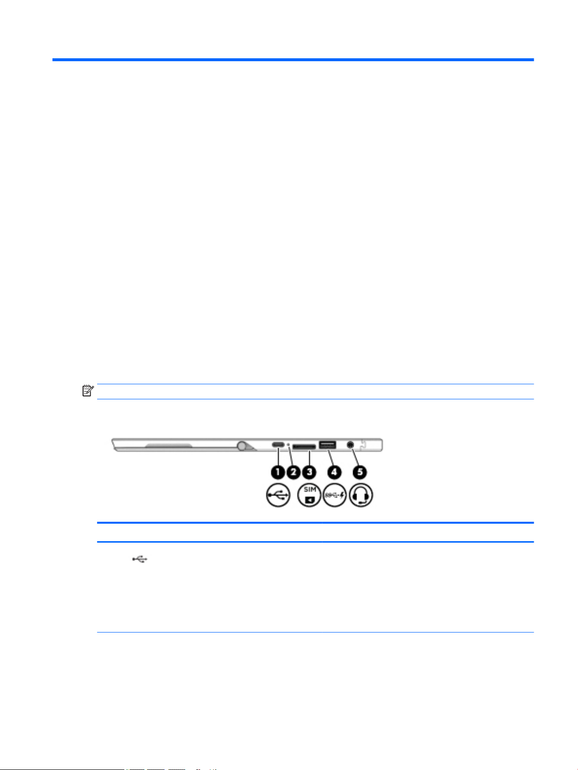
Right
NOTE: The port and connector icons are located on the protective cover.
Component Description
(1) USB Type-C power connector and charging port Connects an AC adapter that has a USB Type-C connector,
supplying power to the computer and, if needed, charging the
computer battery.
– or –
Connects and charges a USB device that has a Type-C
connector, such as a cell phone, camera, activity tracker, or
smartwatch, and provides high-speed data transfer.
(2) Battery light When AC power is connected:
●
White: The battery charge is greater than 90 percent.
●
Amber: The battery charge is from 0 to 90 percent.
●
O: The battery is not charging.
Locating hardware 5

Component Description
When AC power is disconnected (battery not charging):
●
Blinking amber: The battery has reached a low battery
level. When the battery has reached a critical battery
level, the battery light begins blinking rapidly.
●
O: The battery is not charging.
(3) Micro SIM card slot (select products only) Supports a wireless subscriber identity module (SIM) card.
(4) USB 3.x charging port When the computer is on, connects and charges a USB device,
such as a cell phone, camera, activity tracker, or smartwatch,
and provides high-speed data transfer.
Left
(5) Audio-out (headphone)/Audio-in (microphone)
combo jack
Connects optional powered stereo speakers, headphones,
earbuds, a headset, or a television audio cable. Also connects an
optional headset microphone. This jack does not support
optional standalone microphones.
WARNING! To reduce the risk of personal injury, adjust the
volume before putting on headphones, earbuds, or a headset.
For additional safety information, refer to the Regulatory,
Safety, and Environmental Notices.
To access this document:
▲ Select the Start button, select HP Help and Support, and
then select HP Documentation.
‒ or –
▲ Select the Start button, select HP, and then select HP
Documentation.
NOTE: When a device is connected to the jack, the computer
speakers are disabled.
NOTE: The port and connector icons are located on the protective cover.
Component Description
(1) Power button
6 Chapter 2 External component identication
●
When the computer is o, press the button to turn on the
computer.
●
When the computer is on, press the button briey to
initiate Sleep.
●
When the computer is in the Sleep state, press the button
briey to exit Sleep.
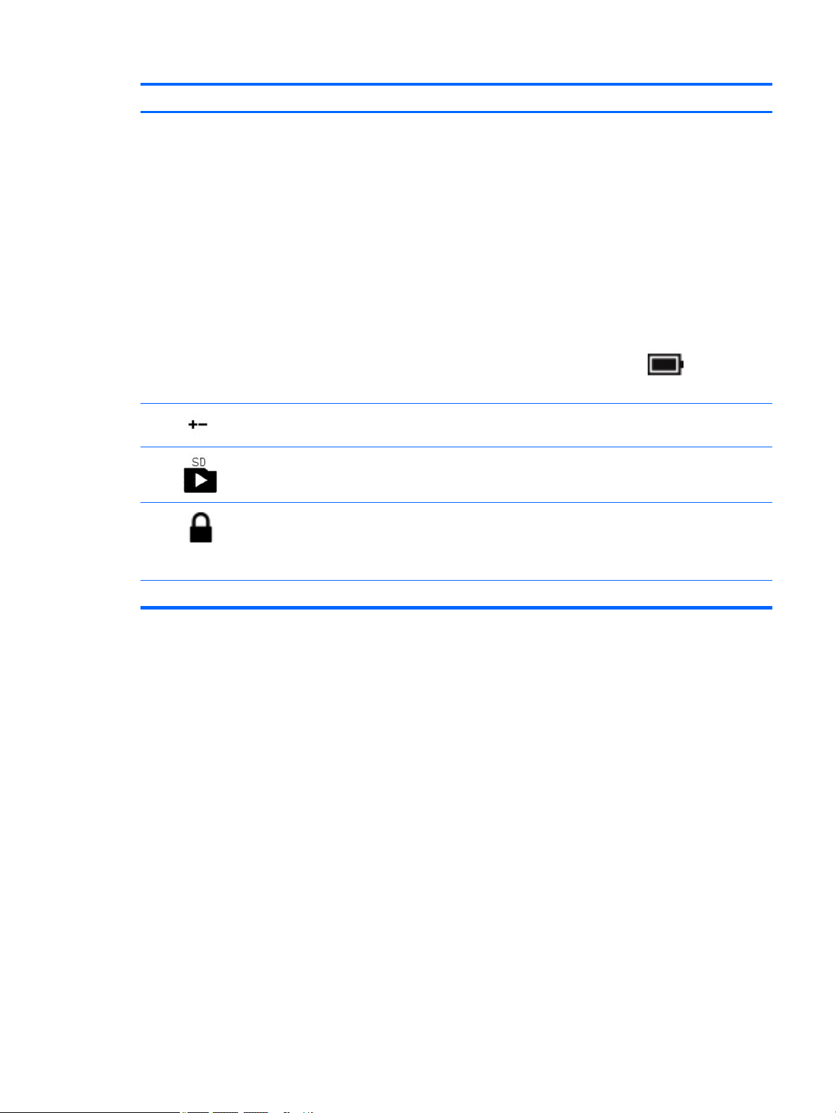
Component Description
●
When the computer is in Hibernation, press the button
briey to exit Hibernation.
CAUTION: Pressing and holding down the power button results
in the loss of unsaved information.
If the computer has stopped responding and shutdown
procedures are ineective, press and hold the power button for
at least 5 seconds to turn o the computer.
To learn more about your power settings, see your power
options.
▲ Type power options in the taskbar search box, and
then select Power Options.
‒ or –
Right-click the Power meter icon , and then select
Power Options.
(2) Volume button Increases or decreases speaker volume incrementally while you
hold down the button.
(3) MicroSD memory card reader Reads optional memory cards that store, manage, share, or
access information.
(4) Security cable slot Attaches an optional security cable to the computer.
NOTE: The security cable is designed to act as a deterrent, but
it may not prevent the computer from being mishandled or
stolen.
(5) Pen lanyard slots Allow you to connect the optional pen using the pen lanyard.
Left 7
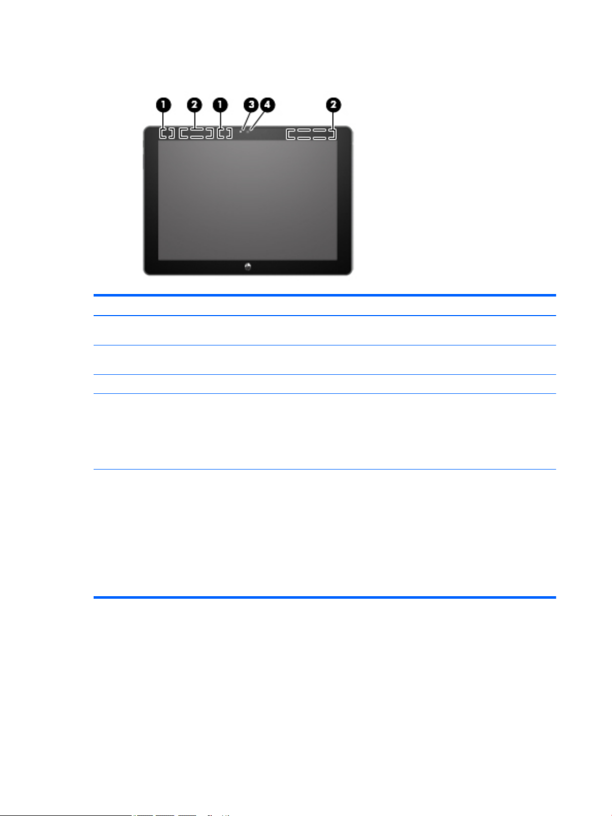
Front
Component Description
(1) WLAN antennas* Send and receive wireless signals to communicate with wireless local
area networks (WLANs).
(2) WWAN antennas* (select products only) Send and receive wireless signals to communicate with wireless wide
area networks (WWANs).
(3) Webcam light On: The webcam is in use.
(4) Webcam Records video and captures photographs. Some models allow you to
video conference and chat online using streaming video.
To use the webcam:
▲ Type camera in the taskbar search box, and then select
Camera.
*The antennas are not visible from the outside of the computer. For optimal transmission, keep the areas immediately around the
antennas free from obstructions.
For wireless regulatory notices, see the section of the Regulatory, Safety, and Environmental Notices that applies to your country or
region.
To access this document:
▲ Select the Start button, select HP Help and Support, and then select HP Documentation.
‒ or –
▲ Select the Start button, select HP, and then select HP Documentation.
8 Chapter 2 External component identication
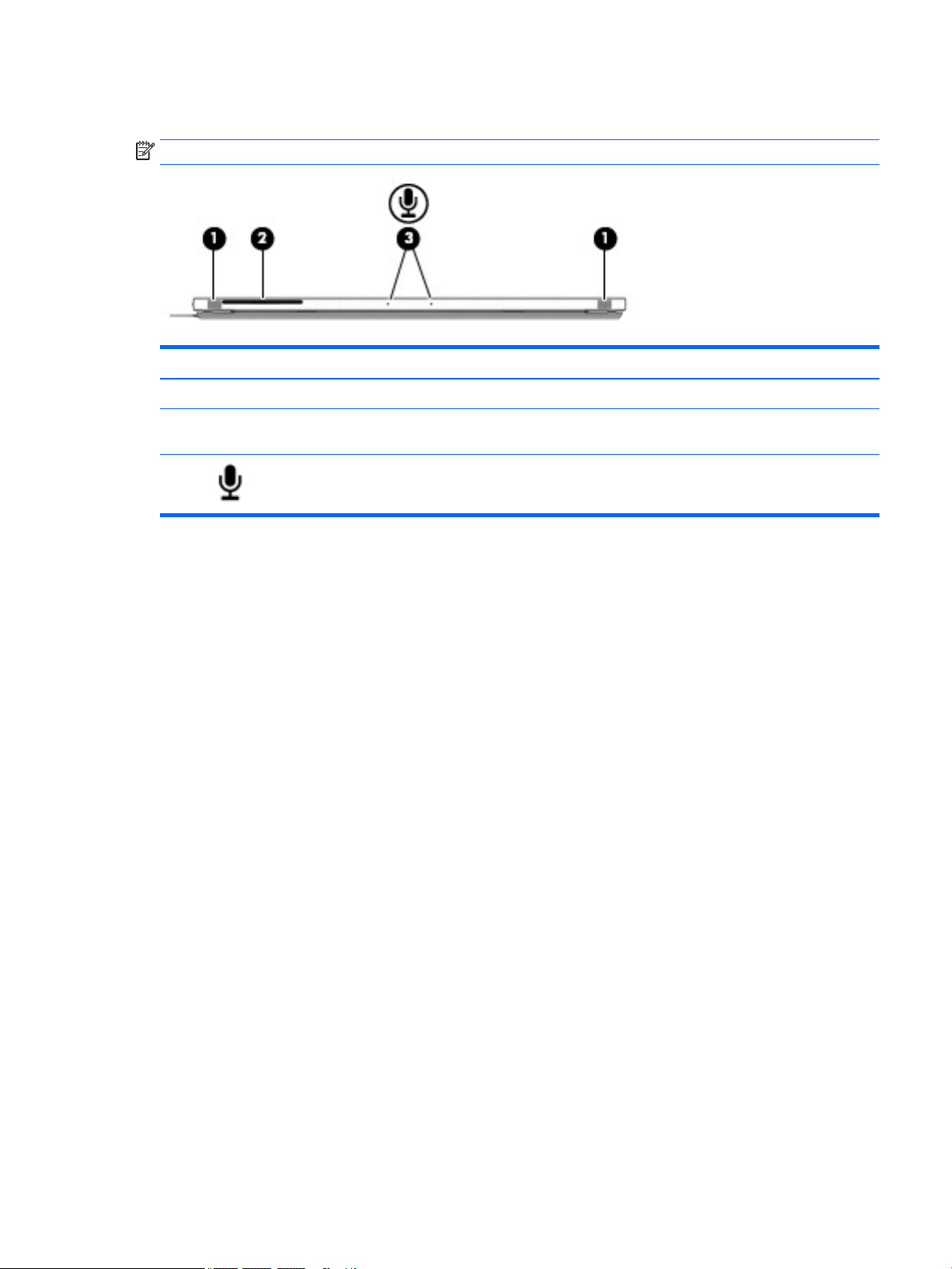
Top
NOTE: The microphone icons are located on the protective cover.
Component Description
(1) Speakers (2) Produce sound.
(2) Smart card
reader
(3) Internal
microphones (2)
Supports optional smart cards.
Record sound.
Top 9
Bottom
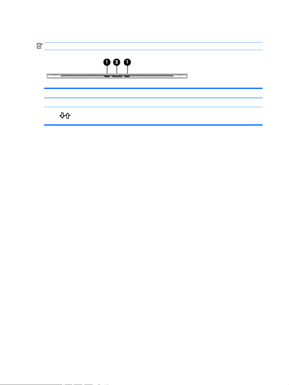
NOTE: The docking connector icon is located on the protective cover.
Component Description
(1) Alignment post connectors (2) Connect to the alignment posts on an optional keyboard.
(2) Docking connector Connects the tablet to an optional keyboard.
10 Chapter 2 External component identication
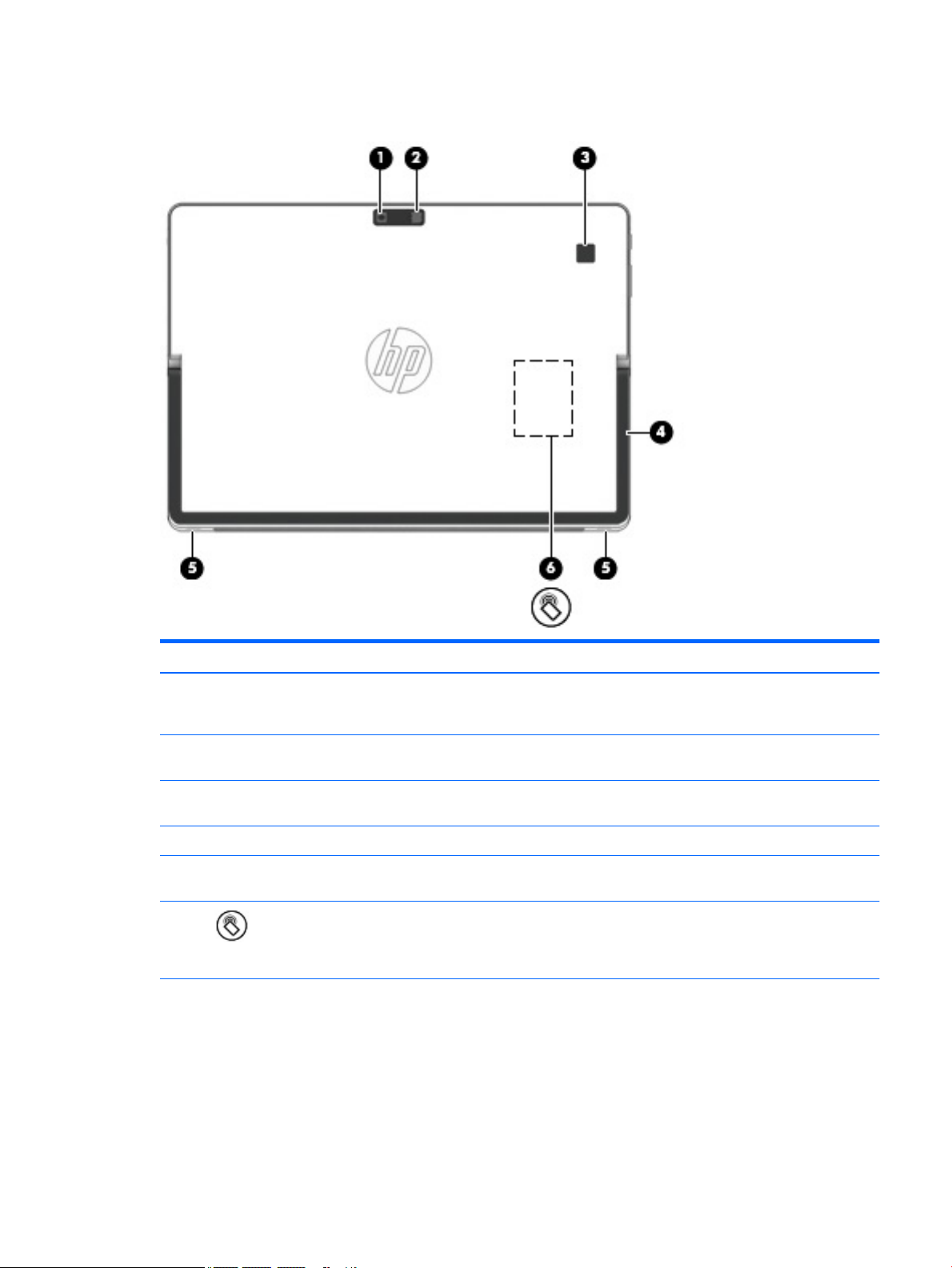
Rear
Component Description
(1) Webcam (rear) Records video and captures photographs. Some
products allow you to video conference and chat
online using streaming video.
(2) Camera ash Provides a camera ash. You can control the ash
using camera apps.
(3) Fingerprint reader (select products only) Allows a ngerprint logon to Windows®, instead
of a password logon.
(4) Kickstand Provides stability and a variety of viewing angles.
(5) Kickstand tabs (2) Provide access to lift the kickstand away from the
back of the computer.
(6) NFC tapping area and antenna* (select products
only)
*The antenna is not visible from the outside of the computer. For optimal transmission, keep the areas immediately around the
antenna free from obstructions.
For wireless regulatory notices, see the section of the Regulatory, Safety, and Environmental Notices that applies to your country or
region.
To access this document:
▲ Select the Start button, select HP Help and Support, and then select HP Documentation.
‒ or –
Send and receive wireless signals to
communicate and transfer information to and
from NFC-compatible devices. To use, tap the NFC
tapping area with an NFC-compatible device.
Rear 11

Component Description
▲ Select the Start button, select HP, and then select HP Documentation.
12 Chapter 2 External component identication
Keyboard components (select products only)
Your computer supports an optional keyboard. This section provides information about the common features
of the supported keyboards.
NOTE: Keyboard appearance and features might vary. For additional details about using the keyboard, refer
to the instructions included with the keyboard.
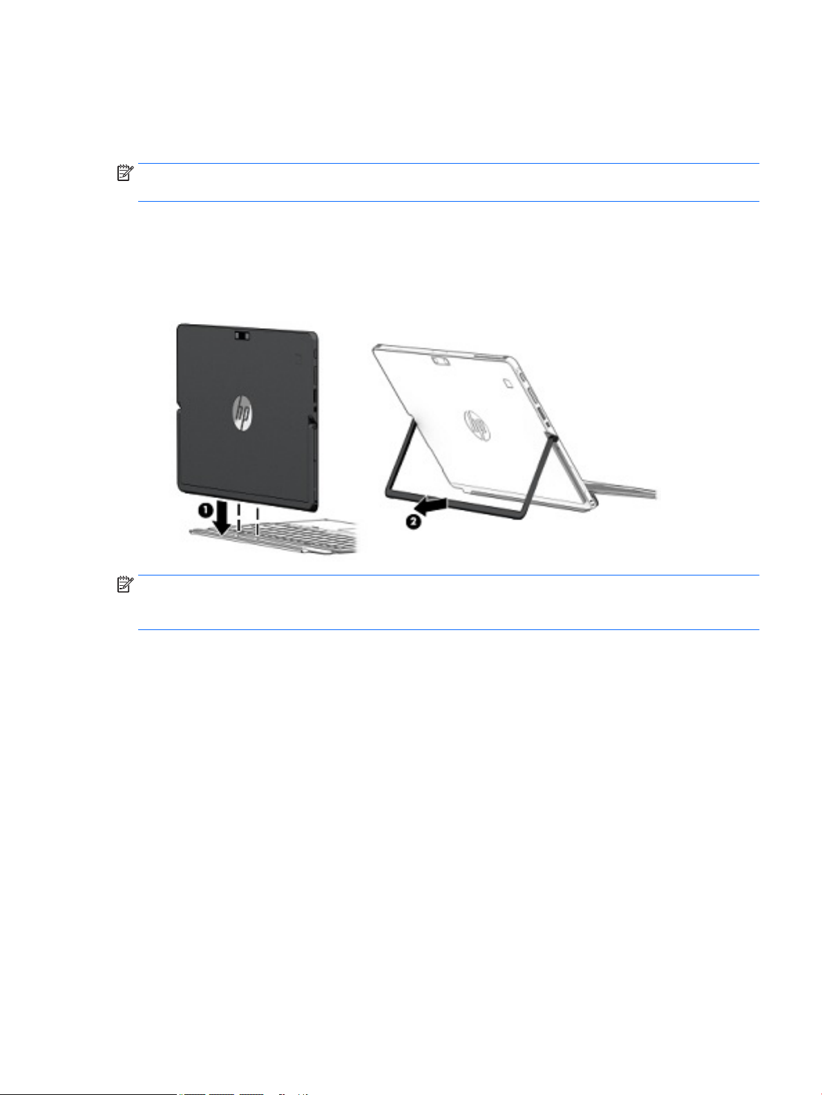
Connecting an optional keyboard
1. To connect an optional keyboard, lower the computer onto the alignment post connectors (1) on the
keyboard until the connectors click into place.
2. Position the kickstand (2) at the desired angle.
NOTE: If you close the kickstand, you can leave the keyboard attached and rotate the keyboard behind the
computer so that the back of the keyboard is against the back of the computer. The keyboard keys and
TouchPad are locked to prevent you from accidently typing while the keyboard is in this position.
Keyboard components (select products only) 13
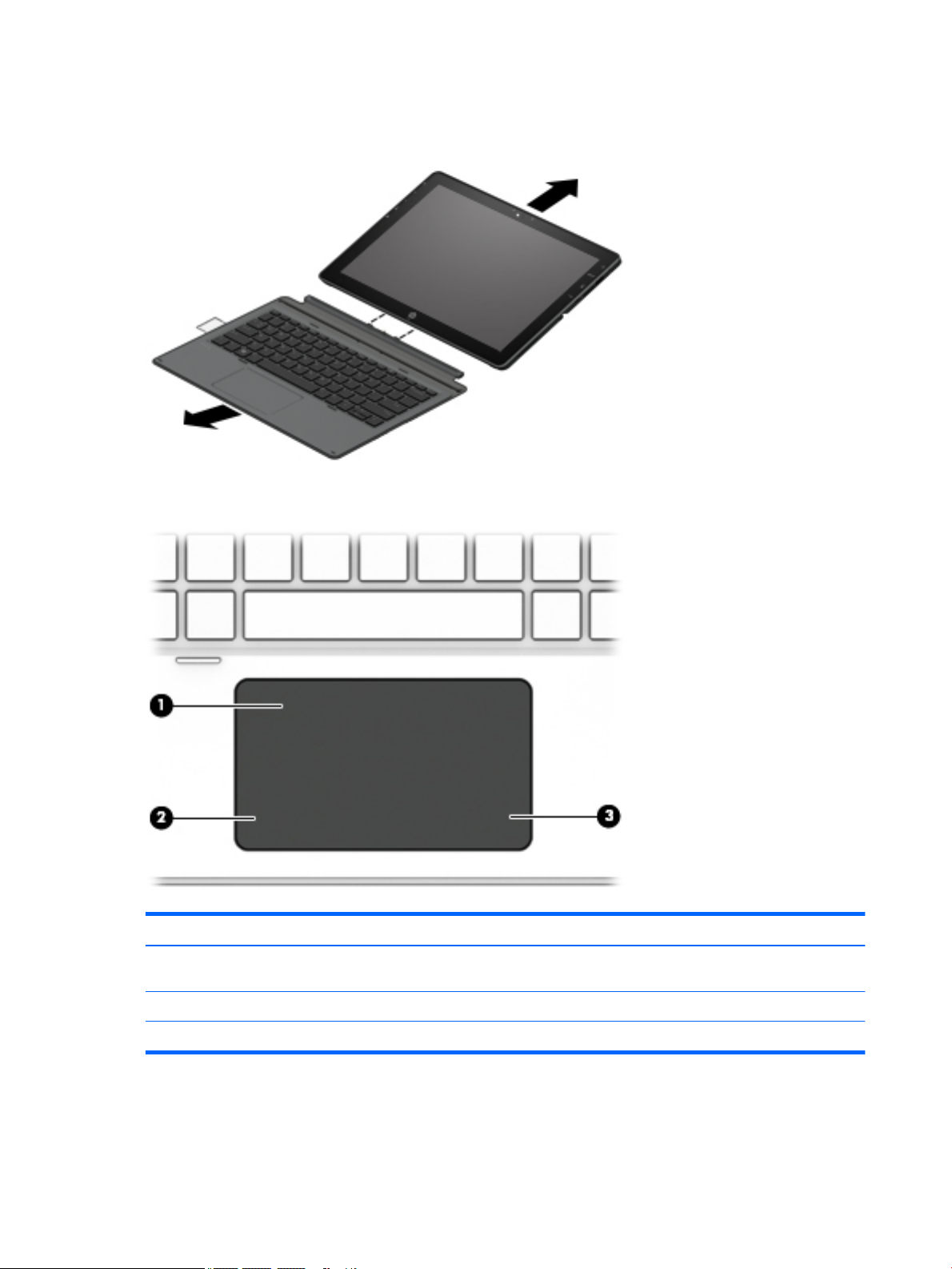
Removing the keyboard
To remove the keyboard, pull the keyboard away from the computer.
TouchPad
Component Description
(1) TouchPad zone Reads your nger gestures to move the pointer or activate
(2) Left TouchPad button Functions like the left button on an external mouse.
(3) Right TouchPad button Functions like the right button on an external mouse.
14 Chapter 2 External component identication
items on the screen.
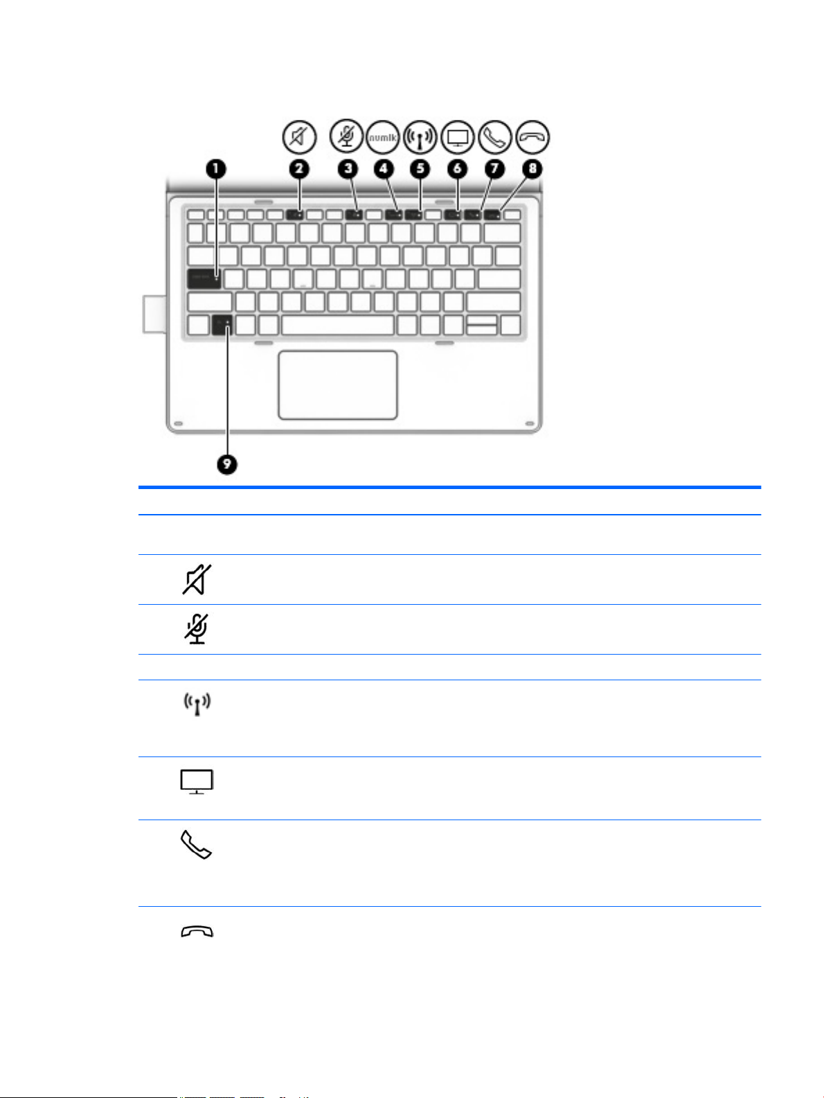
Lights
Component Description
(1) Caps lock light On: Caps lock is on, which switches the key input to all capital
letters.
(2) Mute light
(3) Microphone mute light
(4) Num lk light On: Num lock is on.
(5) Wireless light On: An integrated wireless device, such as a wireless local area
(6) Sharing screen light On: Sharing is on.
(7) Call answer light
●
On: Computer sound is o.
●
O: Computer sound is on.
●
On: Microphone sound is o.
●
O: Microphone sound is on.
network (WLAN) device and/or a Bluetooth® device, is on.
NOTE: On some models, the wireless light is amber when all
wireless devices are o.
NOTE: This feature requires Skype® for Business or Lync® 2013
running on Microsoft Exchange or Oce 365® servers.
●
Blinking: The phone app has an incoming call.
●
On: The phone app has an active call.
NOTE: This feature requires Skype for Business or Lync 2013
running on Microsoft Exchange or Oce 365 servers.
(8) Call end light
●
Blinking: The phone app has an incoming call.
●
On: The phone app has an active call.
Keyboard components (select products only) 15

Component Description
NOTE: This feature requires Skype for Business or Lync 2013
running on Microsoft Exchange or Oce 365 servers.
(9) Fn lock light
●
On: The fn key is locked. For more information, see Hot keys
on page 19.
16 Chapter 2 External component identication
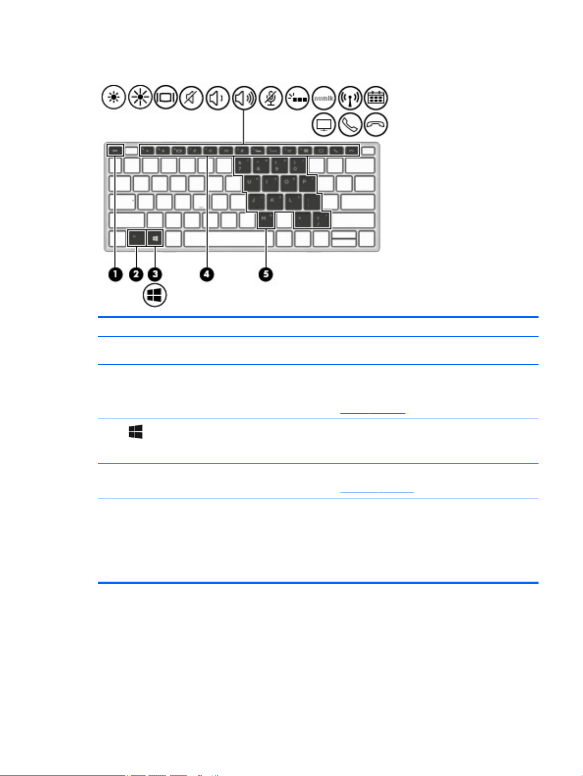
Special keys
Component Description
(1) esc key Displays system information when pressed in combination with
the fn key.
(2) fn key Executes frequently used system functions when pressed in
combination with the esc key or other keys. These key
combinations are called hot keys.
See Hot keys on page 19.
(3) Windows key Opens the Start menu.
NOTE: Pressing the Windows key again will close the Start
menu.
(4) Action keys Execute frequently used system functions.
See Action keys on page 18.
(5) Embedded numeric keypad A numeric keypad superimposed over the keyboard alphabet
keys. When num lk is on, the keypad can be used like an external
numeric keypad. Each key on the keypad performs the function
indicated by the icon in the upper-right corner of the key.
NOTE: If the keypad function is active when the computer is
turned o, that function is reinstated when the computer is
turned back on.
Keyboard components (select products only) 17
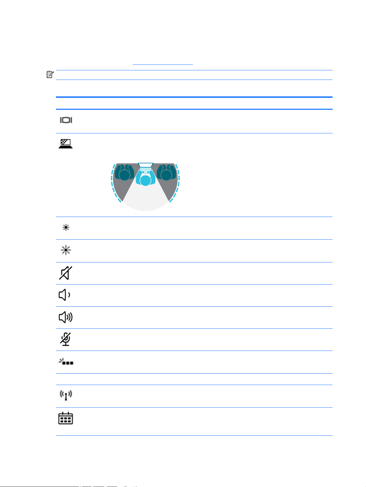
Action keys
An action key performs the function indicated by the icon on the key. To determine which keys are on your
product, see the illustration in Special keys on page 17.
NOTE: All action keys may not be supported by your device.
▲
Icon Description
To use an action key, press and hold the key.
Switches the screen image among display devices connected to the system. For example, if a monitor is
connected to the computer, repeatedly pressing the action key alternates the screen image from the
computer display to the monitor display to a simultaneous display on both the computer and the monitor.
Helps prevent side-angle viewing from onlookers. If needed, decrease or increase brightness for well-lit or
darker environments. Press the action key again to turn o the privacy screen.
NOTE: To quickly turn on the highest privacy setting, press fn+p.
Decreases the screen brightness incrementally as long as you hold down the key.
Increases the screen brightness incrementally as long as you hold down the key.
Mutes or restores speaker sound.
Decreases speaker volume incrementally while you hold down the key.
Increases speaker volume incrementally while you hold down the key.
Mutes the microphone.
Turns the keyboard backlight o or on.
NOTE: To conserve battery power, turn o this feature.
num lk Turns the embedded numeric keypad on and o.
Turns the wireless feature on or o.
NOTE: A wireless network must be set up before a wireless connection is possible.
Provides quick access to your Skype for Business calendar.
NOTE: This feature requires Skype for Business or Lync 2013 running on Microsoft Exchange or Oce 365
servers.
18 Chapter 2 External component identication

Icon Description
Turns the screen sharing function on or o.
NOTE: This feature requires Skype for Business or Lync 2013 running on Microsoft Exchange or Oce 365
servers.
●
Answers a call.
●
Starts a call during a 1–on–1 chat.
●
Places a call on hold.
NOTE: This feature requires Skype for Business or Lync 2013 running on Microsoft Exchange or Oce 365
servers.
●
Ends a call.
●
Declines incoming calls.
●
Ends screen sharing.
NOTE: This feature requires Skype for Business or Lync 2013 running on Microsoft Exchange or Oce 365
servers.
NOTE: The action key feature is enabled at the factory. You can disable this feature by pressing and holding
the fn key and the left shift key. The fn lock light will turn on. After you have disabled the action key feature,
you can still perform each function by pressing the fn key in combination with the appropriate action key.
Hot keys
A hot key is the combination of the fn key and another key.
To use a hot key:
▲
Key Description
C Turns on scroll lock.
E Turns on the insert function.
R Breaks an operation.
S Captures a screen shot.
Labels
The labels axed to the computer provide information you may need when you troubleshoot system
problems or travel internationally with the computer.
IMPORTANT: Check the following locations for the labels described in this section: the bottom of the
computer, inside the battery bay, under the service door, or on the back of the display.
Press the fn key, and then press one of the keys listed in the following table.
●
Service label—Provides important information to identify your computer. When contacting support, you
will probably be asked for the serial number, and possibly for the product number or the model number.
Locate these numbers before you contact support.
Your service label will resemble the example shown below.
Hot keys 19
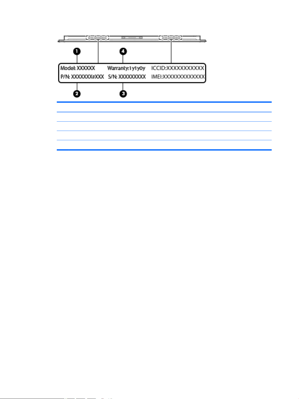
Component
(1) Model name (select products only)
(2) Product number
(3) Serial number
(4) Warranty period
●
Regulatory label(s)—Provide(s) regulatory information about the computer.
●
Wireless certication label(s)—Provide(s) information about optional wireless devices and the approval
markings for the countries or regions in which the devices have been approved for use.
20 Chapter 2 External component identication
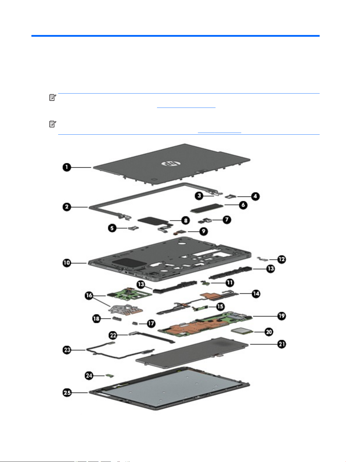
3 Illustrated parts catalog
Computer major components
NOTE: HP continually improves and changes product parts. For complete and current information on
supported parts for your computer, go to http://partsurfer.hp.com, select your country or region, and then
follow the on-screen instructions.
NOTE: Details about your computer, including model, serial number, product key, and length of warranty,
are on the service tag at the bottom of your computer. See Labels on page 19 for details.
Computer major components 21

Item Component Spare part number
(1) Rear cover 918385-001
(2) Kickstand 918394-001
(3) Hinges 918904-001
(4) SIM card tray (included with the Plastics Kit) 918392-001
(5) SD card tray (included with the Plastics Kit) 918392-001
(6) SSD
128 GB M2 SATA-3 918353-001
256 GB Turbo Drive G2 TLC 918354-001
256 GB SATA-3 SED OPAL2 TLC 918356-001
360 GB PCIe TLC 918357-001
512 GB PCIe TLC 918358-001
(7) Rear webcam and ash 918907-001
(8) NFC module and antenna 918399-001
(9) Fingerprint reader (includes cable). The ngerprint reader blank is included in the
Plastics Kit.
(10) Middle frame 918395-001
(11) Front webcam 918906-001
(12) USB Type-C bracket (included with the Plastics Kit) 918392-001
(13) Speakers 921406-001
(14) Antennas, WLAN dual 918901-001
(15) Microphone board 918387-001
(16) Smart card reader board and bracket 918386-001
(17) Power button (included with the Plastics Kit) 918392-001
(18) Volume button (included with the Plastics Kit) 918392-001
(19) System board
UMA graphics Core M-7Y30 4 GB with Windows operating system and WLAN capability 918345-601
UMA graphics Core i5-7Y54 4 GB with Windows operating system and WLAN capability 918346-601
UMA graphics Core i5-7Y54 8 GB with Windows operating system and WLAN capability 918347-601
UMA graphics Core i5-7Y57 4 GB with Windows operating system and WLAN capability 918348-601
UMA graphics Core i5-7Y57 8 GB with Windows operating system and WLAN capability 918349-601
918398-001
UMA graphics Core i7-7Y75 8 GB with Windows operating system and WLAN capability 918350-601
UMA graphics Pentium 4410Y 4 GB with Windows operating system and WLAN capability 918351-601
(20) WWAN module (select products only)
Foxconn HP lt4120 LTE/EVDO/HPSA+ with GPS M.2 with antennas 922446-001
22 Chapter 3 Illustrated parts catalog

Item Component Spare part number
Fibocom HP hs3210 WW HSPA+ without GPS +M.2 with antennas 922445-001
Huawei HP It4132, LTE/HSPA+ 4G with GPS M.2 with antennas 922444-001
GPS module, u-blox EVA-M8M M.2/USB WW 918905-001
(21) Battery, 4 C, 41 WH, 2.7 Ah, Lithium Ion (LI) 860708-855
(22) POGO connector (includes cable) 918389-001
(23) Display cable kit (includes touch cable and display panel cable) 918391-001
(24) Hall eects sensor board 918388-001
(25) Panel, 12 inch LCD WUXGA+BV LED UWVA, with touch glass, touch board, and bezel 918352-001
Miscellaneous parts
Component Spare part number
Adapter
45 W adapter non-Power Factor Correction (PFC) wall mount USB Type-C, 3 pin 860210-850
65 W adapter non-PFC wall mount 3 pin, 4.5 mm 710412-001
65 W adapter non-PFC wall mount USB Type-C, 3 pin 860209-850
HP USB Type-C to DisplayPort adapter 831753-001
HP USB Type-C to HDMI adapter 831752-001
HP USB Type-C to USB 3.0 adapter 814618-001
HP USB Type-C to Gigabit RJ-45 adapter 829941-001
HP USB Type-C to VGA adapter 831751-001
Cable, HP USB Type-C to 3 mm and 4.5 mm adapter cable 814813-001
Case
HP x2 1012 Protective Case 841972-001
HP Retail Case 12 907639-001
HP Retail Case 12 with handstrap 912975-001
HP Retail Case 12 for mounting, with tape 912976-001
Docking station, HP Elite USB Type-C Docking Station 844549-001
Keyboard, for a complete list of part numbers see Keyboard (select products only) on page 31
Pen, HP Active Pen 846410-001
Plastics Kit, includes USB bracket, power button, volume button, SD card tray, thermal plastic, SIM card
tray, ngerprint reader blank, SIM card tray blank, main upholder, auxiliary upholder
918392-001
Power cord, AC power line
For use in Argentina, 1.83 m AC adapter 401300-001
For use in Argentina, 1.0 m 401300-011
Miscellaneous parts 23

Component Spare part number
For use in Australia, 1.0 m 213356-013
For use in Brazil, 1.83 m AC adapter 438722-001
For use in Brazil, 1.0 m 438722-008
For use in the People’s Republic of China, 1.83 m AC adapter 286497-001
For use in the People’s Republic of China, 1.0 m 286497-013
For use in Denmark, 1.83 m AC adapter 213353-001
For use in Denmark, 1.0 m 213353-013
For use in Europe, 1.83 m AC adapter 213350-001
For use in Europe, 1.0 m 213350-014
For use in India, 1.83 m AC adapter 404827-001
For use in India, 1.0 m 404827-008
For use in Israel, 1.83 m AC adapter 398063-001
For use in Israel, 1.0 m 398063-008
For use in Italy, 1.83 m AC adapter 213352-001
For use in Italy, 1.0 m 213352-013
Adapter, for use in Japan, 1.0 m 226768-001
For use in Japan, with ground lead 349756-001
For use in Korea, 1.0 m 267836-001
For use in North America, 1.0 m 213349-015
For use in South Africa, 1.83 m AC adapter 361240-001
For use in South Africa, 1.0 m 361240-007
For use in Switzerland, 1.83 m AC adapter 213354-001
For use in Switzerland, 1.0 m 213354-013
For use in Taiwan, 1.83 m AC adapter 393313-001
For use in Taiwan, 1.0 m 393313-007
For use in Thailand, 1.83 m AC adapter 285096-001
For use in Thailand, 1.0 m 285096-012
For use in the United Kingdom and Singapore, 1.83 m AC adapter 213351-001
For use in the United Kingdom, 1.0 m 213351-013
For use in the United States, 1.83 m AC adapter 213349-001
Power cord with duck head
For use in Europe and Korea 854703-001
For use in the United States 854702-001
Screw Kit 918393-001
24 Chapter 3 Illustrated parts catalog
 Loading...