

HP ProLiant DL360p G8 User Manual

HP ProLiant DL360p Gen8 Server
Part Number: 664724-004
User Guide
Abstract
This document is for the person who installs, administers, and troubleshoots servers and storage systems. HP assumes you are qualified in the
servicing of computer equipment and trained in recognizing hazards in products with hazardous energy levels.
March 2013
Edition: 4

© Copyright 2012, 2013 Hewlett-Packard Development Company, L.P.
The information contained herein is subject to change without notice. The only warranties for HP products and services are set forth in the express
warranty statements accompanying such products and services. Nothing herein should be construed as constituting an additional warranty. HP shall
not be liable for technical or editorial errors or omissions contained herein.
Microsoft® and Windows® are U.S. registered trademarks of Microsoft Corporation.
Bluetooth® is a trademark owned by its proprietor and used by Hewlett-Packard Company under license.
Intel® Xeon® is a trademark of Intel Corporation in the U.S. and other countries.

Contents
Introduction .................................................................................................................................. 6
Server features .......................................................................................................................................... 6
Component identification ............................................................................................................... 7
Front panel components ............................................................................................................................. 7
Front panel LEDs and buttons ...................................................................................................................... 9
Rear panel components ............................................................................................................................ 10
Rear panel LEDs and buttons ..................................................................................................................... 11
System board components ........................................................................................................................ 12
DIMM slots ................................................................................................................................... 13
System maintenance switch ............................................................................................................. 14
NMI jumper .................................................................................................................................. 14
Systems Insight Display LEDs ..................................................................................................................... 15
Systems Insight Display LED combinations ................................................................................................... 16
Device numbers ...................................................................................................................................... 17
Drive LED definitions ................................................................................................................................ 18
Fan modules ........................................................................................................................................... 18
Operations ................................................................................................................................. 20
Power up the server ................................................................................................................................. 20
Power down the server ............................................................................................................................. 20
Extend the server from the rack ................................................................................................................. 20
Remove the server from the rack ................................................................................................................ 21
Access the HP Systems Insight Display ........................................................................................................ 21
Remove the access panel.......................................................................................................................... 23
Install the access panel............................................................................................................................. 23
Remove the FBWC capacitor pack ............................................................................................................ 23
Remove the PCI riser cage ........................................................................................................................ 24
Install the PCI riser cage ........................................................................................................................... 25
Setup ......................................................................................................................................... 27
Optional installation services .................................................................................................................... 27
Rack planning resources........................................................................................................................... 27
Optimum environment .............................................................................................................................. 27
Space and airflow requirements ...................................................................................................... 28
Temperature requirements ............................................................................................................... 28
Power requirements ....................................................................................................................... 29
Electrical grounding requirements .................................................................................................... 29
Connecting a DC power cable to a DC power source ........................................................................ 29
Rack warnings ........................................................................................................................................ 30
Contents of the server shipping carton ........................................................................................................ 31
Installing hardware options ....................................................................................................................... 31
Installing the server into the rack ................................................................................................................ 31
Powering on and selecting boot options ..................................................................................................... 33
Installing the operating system................................................................................................................... 33
Registering the server ............................................................................................................................... 34
Hardware options installation
....................................................................................................... 35
Contents 3

Introduction ............................................................................................................................................ 35
Processor and fan module option .............................................................................................................. 35
Memory options ...................................................................................................................................... 40
HP SmartMemory .......................................................................................................................... 42
Memory subsystem architecture ....................................................................................................... 42
Single-, dual-, and quad-rank DIMMs ............................................................................................... 42
DIMM identification ....................................................................................................................... 43
Memory configurations ................................................................................................................... 44
General DIMM slot population guidelines ......................................................................................... 45
Installing a DIMM .......................................................................................................................... 46
Hot-plug hard drive guidelines .................................................................................................................. 47
Removing the hard drive blank ........................................................................................................ 48
Installing a hot-plug hard drive ........................................................................................................ 48
DVD-ROM and DVD-RW drive option ......................................................................................................... 49
Controller options .................................................................................................................................... 52
Installing the cache module ............................................................................................................. 53
Installing the FBWC capacitor pack ................................................................................................. 54
Front video adapter option ....................................................................................................................... 55
FlexibleLOM option ................................................................................................................................. 56
Expansion board option ........................................................................................................................... 58
Redundant hot-plug power supply option .................................................................................................... 59
48V DC power supply option ................................................................................................................... 61
Rack bezel option ................................................................................................................................... 65
HP Trusted Platform Module option ............................................................................................................ 66
Installing the Trusted Platform Module board ..................................................................................... 66
Retaining the recovery key/password .............................................................................................. 68
Enabling the Trusted Platform Module ............................................................................................... 68
Cabling ..................................................................................................................................... 69
Cabling overview .................................................................................................................................... 69
Hard drive backplane cabling .................................................................................................................. 69
DVD-ROM and DVD-RW drive cabling ....................................................................................................... 70
Chipset SATA cable option ....................................................................................................................... 70
FBWC capacitor pack cabling .................................................................................................................. 74
Software and configuration utilities ............................................................................................... 75
Server mode ........................................................................................................................................... 75
HP product QuickSpecs ............................................................................................................................ 75
HP iLO Management Engine ..................................................................................................................... 75
HP iLO ......................................................................................................................................... 75
Intelligent Provisioning .................................................................................................................... 77
HP Insight Remote Support software ................................................................................................. 79
Scripting Toolkit ............................................................................................................................ 79
HP Service Pack for ProLiant ..................................................................................................................... 79
HP Smart Update Manager ............................................................................................................. 80
HP ROM-Based Setup Utility ..................................................................................................................... 80
Using RBSU .................................................................................................................................. 81
Auto-configuration process .............................................................................................................. 81
Boot options ................................................................................................................................. 82
Configuring AMP modes ................................................................................................................ 82
Re-entering the server serial number and product ID ........................................................................... 82
Utilities and features ................................................................................................................................ 83
Array Configuration Utility .............................................................................................................. 83
Option ROM Configuration for Arrays ............................................................................................. 84
Contents 4

ROMPaq utility .............................................................................................................................. 84
Automatic Server Recovery ............................................................................................................. 84
USB support .................................................................................................................................. 84
Redundant ROM support ................................................................................................................ 85
Keeping the system current ....................................................................................................................... 85
Drivers ......................................................................................................................................... 85
Software and firmware ................................................................................................................... 86
Version control .............................................................................................................................. 86
HP operating systems and virtualization software support for ProLiant servers ........................................ 86
HP Technology Service Portfolio ...................................................................................................... 87
Change control and proactive notification ........................................................................................ 87
Troubleshooting .......................................................................................................................... 88
Troubleshooting resources ........................................................................................................................ 88
System battery ............................................................................................................................ 89
Regulatory information ................................................................................................................ 91
Safety and regulatory compliance ............................................................................................................. 91
Turkey RoHS material content declaration ................................................................................................... 91
Ukraine RoHS material content declaration ................................................................................................. 91
Warranty information .............................................................................................................................. 91
Electrostatic discharge ................................................................................................................. 92
Preventing electrostatic discharge .............................................................................................................. 92
Grounding methods to prevent electrostatic discharge .................................................................................. 92
Specifications ............................................................................................................................. 93
Environmental specifications ..................................................................................................................... 93
Server specifications ................................................................................................................................ 93
Power supply specifications ...................................................................................................................... 93
HP 460 W CS power supply (92% efficiency) ................................................................................... 94
HP 460 W CS HE power supply (94% efficiency) .............................................................................. 94
HP 750 W CS power supply (92% efficiency) ................................................................................... 95
HP 750 W CS HE power supply (94% efficiency) .............................................................................. 95
HP 750 W DC CS HE power supply (94% efficiency) ........................................................................ 95
HP 1200 W CS HE power supply (94% efficiency) ............................................................................ 96
Hot-plug power supply calculations ............................................................................................................ 97
Support and other resources ........................................................................................................ 98
Before you contact HP .............................................................................................................................. 98
HP contact information ............................................................................................................................. 98
Customer Self Repair ............................................................................................................................... 98
Acronyms and abbreviations ...................................................................................................... 106
Documentation feedback ........................................................................................................... 109
Index ....................................................................................................................................... 110
Contents 5

Introduction
Server features
The HP ProLiant DL360p Gen8 Server comes with industry leading performance, efficiency, capacity, and
reliability in a 1U space. The server provides enterprise-class design for performance workloads with
versatile and future requirements, and it is ideal for performance-driven computing and storage in a dense
rack package.
The HP ProLiant DL360p Gen8 Server is a space-conscious, 2-processor performance server with industry
leading feature sets. It is built to protect your investment with reliability, accessibility, and serviceability
features designed in.
The server includes the following features:
• 8 SFF or 4 LFF drive models available for 8 TB or 12 TB capacity, with optional DVD. 10 SFF drive
model available for 10 TB capacity, without optional DVD.
• Intel Xeon E5-2600 processor, with a choice of 2/4/6/8 cores, and speeds up to 3.3 GHz
• HP Smart Socket Guide for quick, precise intelligent processor installation
• 24 DIMM slots available for DDR3 Memory, and up to 1600 MHz speeds with 768 GB maximum
capacity
• HP Smart Array P420i Controller with flash-backed write cache options
• HP FlexibleLOM options—4x1 Gb-E, 2x10 Gb-E, 2xIB and FlexFabric options
• 2 PCIe 3.0 slots:
o x16 (full height, half length)
o x8 (low profile)
• HP iLO Management Engine (HP iLO 4) with Active Health System, HP power/cooling management,
Agentless Management, and Intelligent Provisioning
For more information about product features, specifications, options, configurations, and compatibility, see
the product QuickSpecs on the HP Product Bulletin website (http://www.hp.com/go/productbulletin).
Introduction 6
Component identification
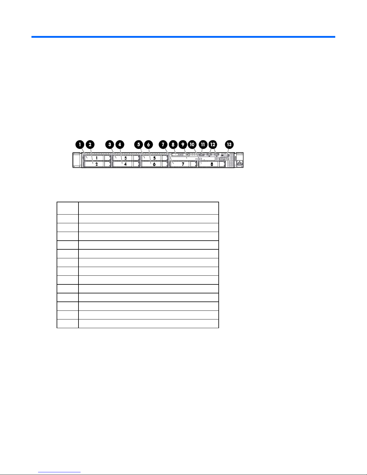
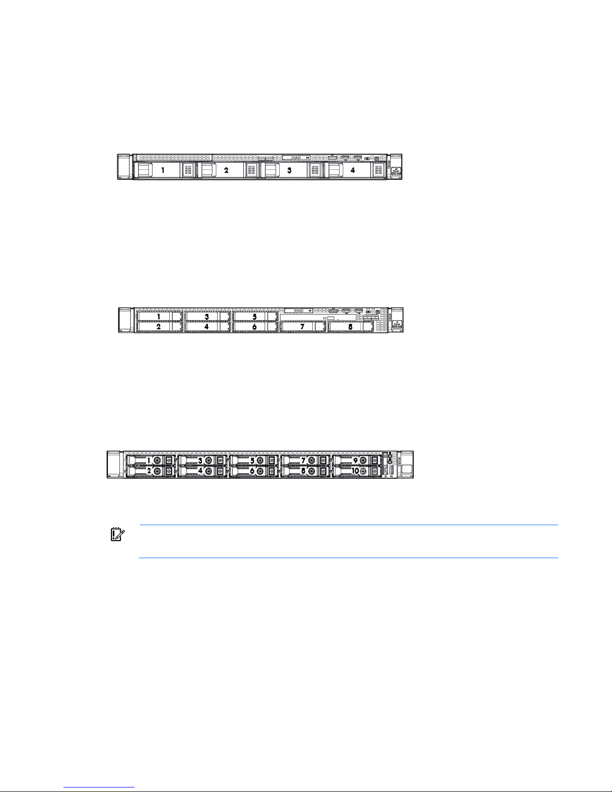
SAS/SATA/SSD drive bay 6
Front panel components
• 8 SFF
Item Description
1
2
3
4
5
6
7
8
9
10
11
12
13
SAS/SATA/SSD drive bay 1
SAS/SATA/SSD drive bay 2
SAS/SATA/SSD drive bay 3
SAS/SATA/SSD drive bay 4
SAS/SATA/SSD drive bay 5
SAS/SATA/SSD drive bay 7
Systems Insight Display
DVD-ROM drive (optional)
SAS/SATA/SSD drive bay 8
Front video connector (front video port adapter required)
USB connectors (2)
Serial number tab
Component identification 7
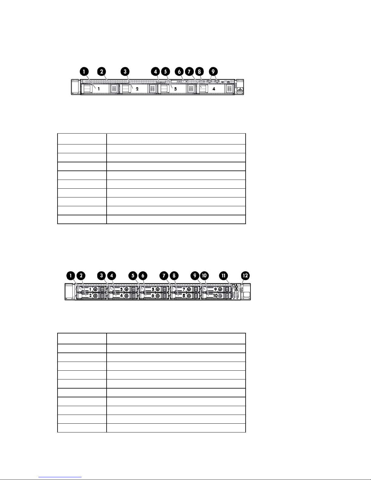
• 4 LFF
SAS/SATA/SSD drive bay 3
Item Description
1
2
3
4
5
6
7
8
9
SAS/SATA/SSD drive bay 1
DVD-ROM drive (optional)
SAS/SATA/SSD drive bay 2
Serial number tab
Systems Insight Display
SAS/SATA/SSD drive bay 4
Front video connector (front video port adapter required)
USB connectors (2)
• 10 SFF
Item Description
1
2
3
4
5
6
7
8
9
10
SAS/SATA/SSD drive bay 1
SAS/SATA/SSD drive bay 2
SAS/SATA/SSD drive bay 3
SAS/SATA/SSD drive bay 4
SAS/SATA/SSD drive bay 5
SAS/SATA/SSD drive bay 6
SAS/SATA/SSD drive bay 7
SAS/SATA/SSD drive bay 8
SAS/SATA/SSD drive bay 9
SAS/SATA/SSD drive bay 10
Component identification 8
Item Description
11
12
Systems Insight Display
USB connector
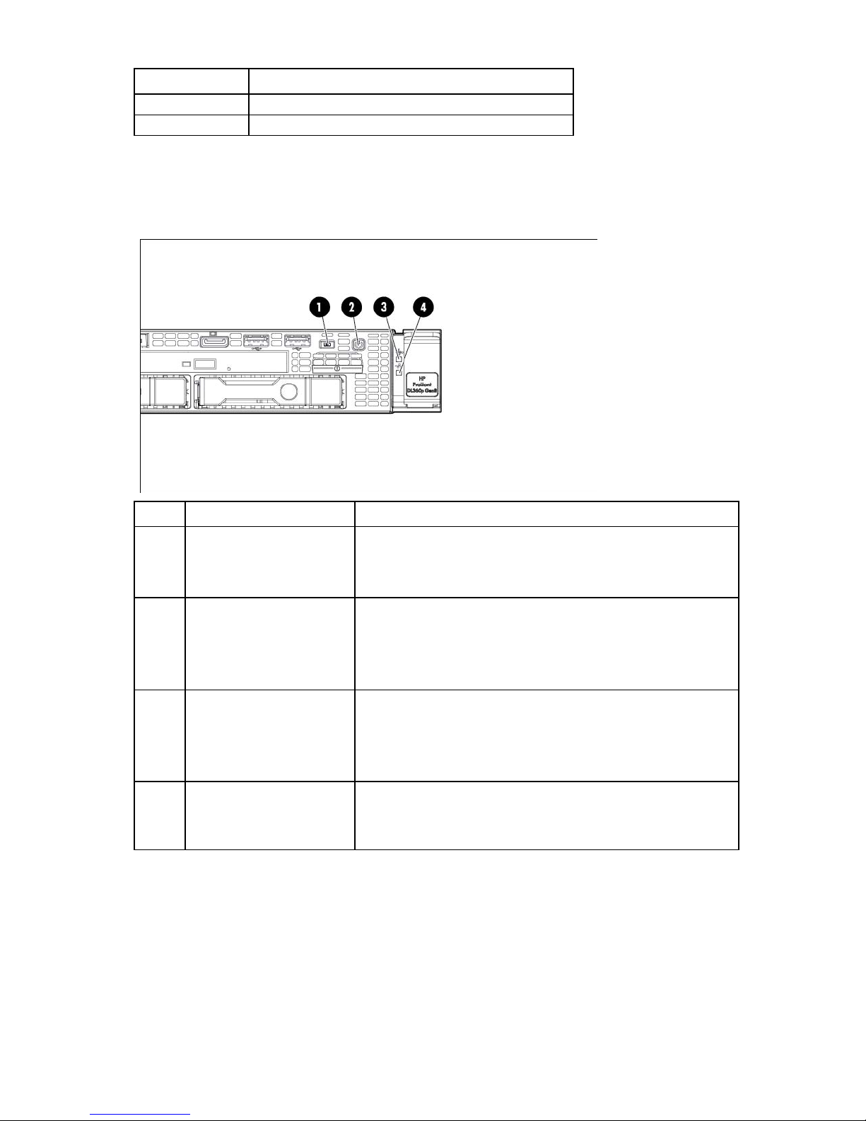
Front panel LEDs and buttons
• 8 SFF or 4 LFF
Item Description Status
1
2
3
4
*Facility power is not present, power cord is not attached, no power supplies are installed, power supply failure has
occurred, or the power button cable is disconnected.
**To identify components in a degraded or critical state, see the Systems Insight Display LEDs (on page 15), check
iLO/BIOS logs, and reference the server troubleshooting guide.
UID button/LED Solid blue = Activated
Flashing blue (1 Hz/cycle per sec) = Remote management or
firmware upgrade in progress
Off = Deactivated
Power On/Standby button
and system power LED
Solid green = System on
Flashing green (1 Hz/cycle per sec) = Performing power on sequence
Solid amber = System in standby
Off = No power present*
Health LED Solid green = Normal
Flashing amber = System degraded
Flashing red (1 Hz/cycle per sec) = System critical
Fast-flashing red (4 Hz/cycles per sec) = Power fault**
NIC status LED Solid green = Link to network
Flashing green (1 Hz/cycle per sec) = Network active
Off = No network activity
Component identification 9

• 10 SFF
Item Description Status
1
2
3
4
*Facility power is not present, power cord is not attached, no power supplies are installed, power supply failure has
occurred, or the power button cable is disconnected.
**To identify components in a degraded or critical state, see the Systems Insight Display LEDs (on page 15), check
iLO/BIOS logs, and reference the server troubleshooting guide.
UID button/LED Solid blue = Activated
Flashing blue (1 Hz/cycle per sec) = Remote management or
firmware upgrade in progress
Off = Deactivated
Power On/Standby button
and system power LED
Solid green = System on
Flashing green (1 Hz/cycle per sec) = Performing power on sequence
Solid amber = System in standby
Off = No power present*
Health LED Solid green = Normal
Flashing amber = System degraded
Flashing red (1 Hz/cycle per sec) = System critical
Fast-flashing red (4 Hz/cycles per sec) = Power fault**
NIC status LED Solid green = Link to network
Flashing green (1 Hz/cycle per sec) = Network active
Off = No network activity
Rear panel components
Component identification 10
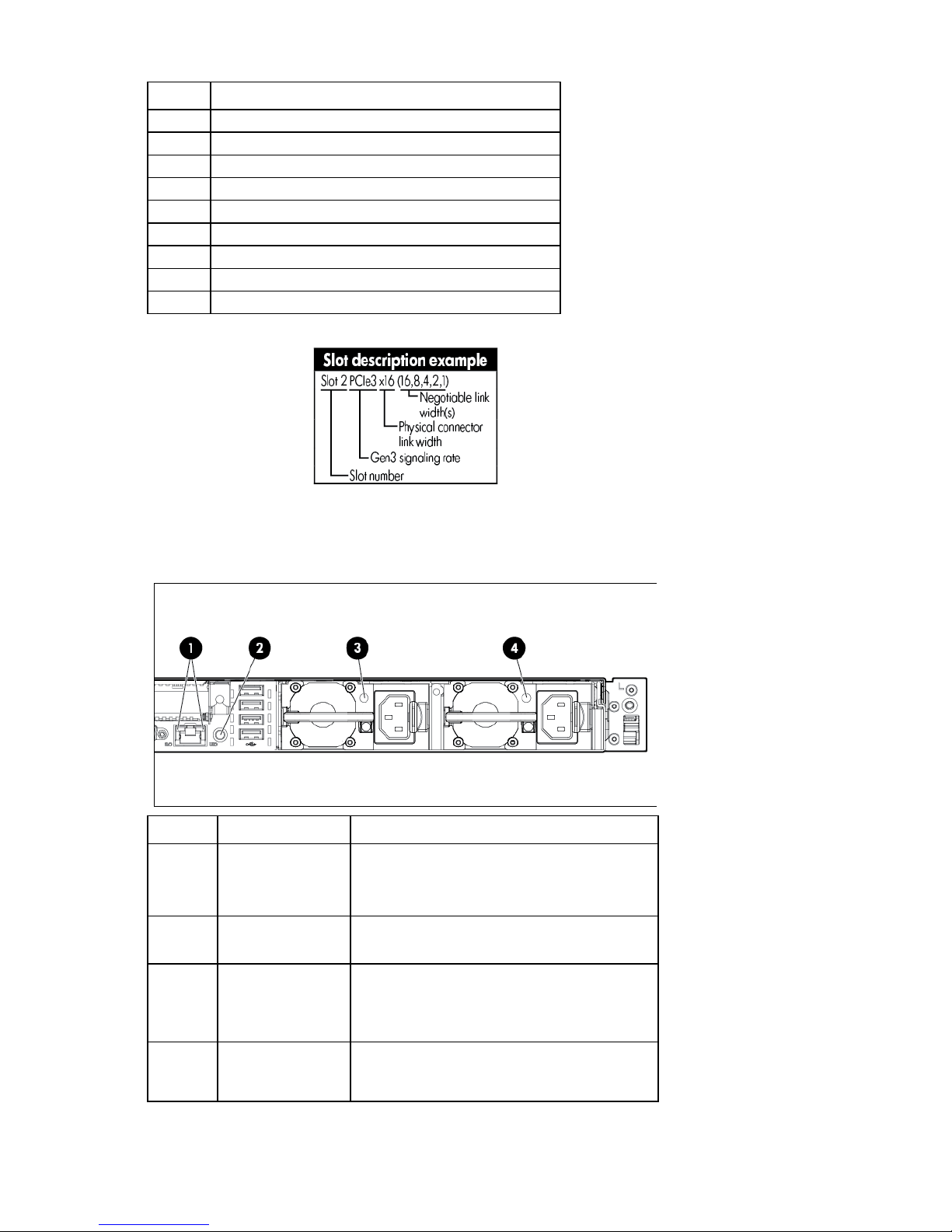
Power supply bay 2
Item Description
1
2
3
4
5
6
7
8
9
Slot 2 PCIe 3.0 x16 (full height/half length)
FlexibleLOM ports (Shown: 4x1Gb / Optional: 2x10Gb)
Video connector
Serial connector
Slot 1 PCIe 3.0 x8 (low profile)
iLO management port
USB connectors (4)
Power supply bay 1
Rear panel LEDs and buttons
Item Description Status
1L
1R
HP iLO/standard
NIC activity LED
HP iLO/standard
NIC link LED
Solid green = Activity exists.
Flashing green = Activity exists.
Off = No activity exists.
Solid green = Link exists.
Off = No link exists.
2
3
UID button/LED Solid blue = Identification is activated.
Power supply 2 LED Solid green = Normal
Flashing blue = System is being managed
remotely.
Off = Identification is deactivated.
Off = One or more of the following conditions
exists:
Component identification 11
Item Description Status
•
•
•
•
•
•
•
•
AC power unavailable
Power supply failed
Power supply in standby mode
Power supply exceeded current limit
4
Power supply 1 LED Solid green = Normal
Off = One or more of the following conditions
exists:
AC power unavailable
Power supply failed
Power supply in standby mode
Power supply exceeded current limit
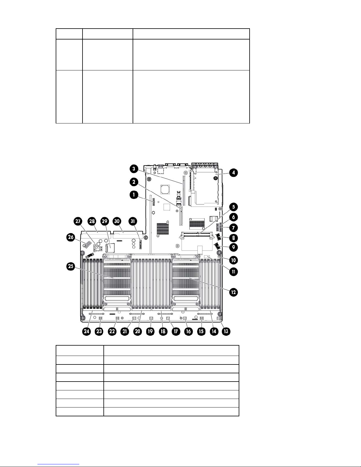
System board components
Item Description
1
2
3
4
5
6
7
TPM connector
PCIe x8 riser connector
PCIe x16 riser connector
FlexibleLOM
SAS cache module connector
Front LED/Power cable connector
Front USB/Video cable connector
Component identification 12
Fan module 7 connector
Item Description
8
9
10
11
12
13
14
15
16
17
18
19
20
21
22
23
24
25
26
27
28
29
30
31
SAS connector B (Drives 5–8)
SAS connector A (drives 1–4)
NMI jumper
System maintenance switch
Processor 1
Fan module 8 connector
Processor 1 DIMM slots
Fan module 6 connector
Fan module 5 connector
Processor 1 DIMM slots
Fan module 4 connector
Processor 2 DIMM slots
Fan module 3 connector
Fan module 2 connector
Fan module 1 connector
Processor 2 DIMM slots
Processor 2
Drive backplane power connector
Internal USB connector
Power supply connector 1
SD card slot
Power supply connector 2
Optical SATA connector
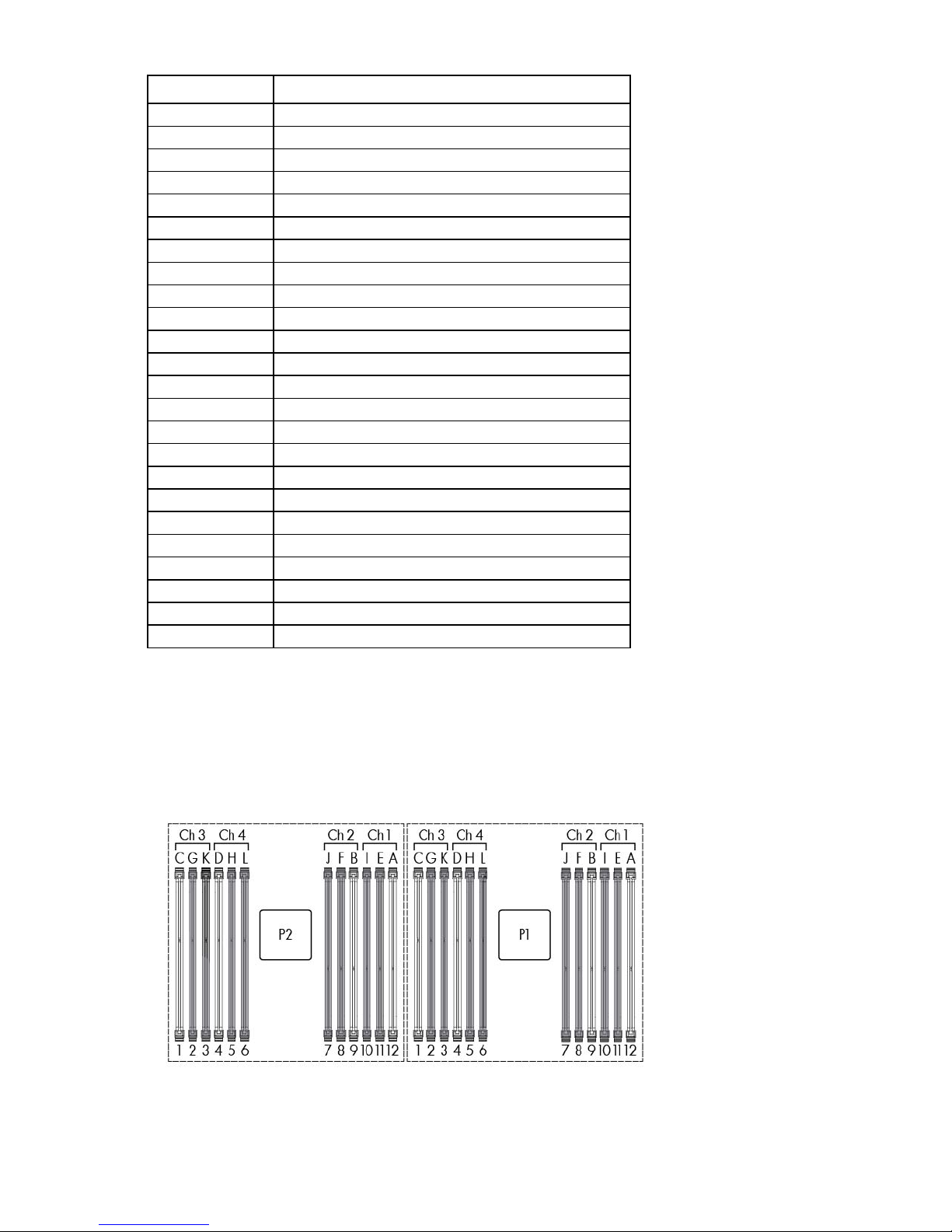
DIMM slots
DIMM slots are numbered sequentially (1 through 12) for each processor. The supported AMP modes use the
letter assignments for population guidelines.
Component identification 13
Off
Off = System configuration can be
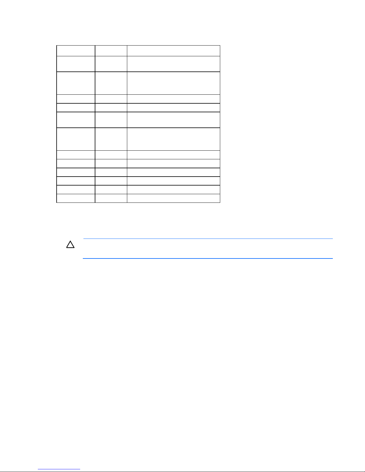
System maintenance switch
Position Default Function
S1
S2
S3
S4
S5
S6
S7
S8
S9
S10
S11
S12
Off Off = HP iLO security is enabled.
On = HP iLO security is disabled.
changed.
On = System configuration is locked.
Off Reserved
Off Reserved
Off Off = Power-on password is enabled.
On = Power-on password is disabled.
Off Off = No function
On = ROM reads system configuration
as invalid.
— Reserved
— Reserved
— Reserved
— Reserved
— Reserved
— Reserved
To access redundant ROM, set S1, S5, and S6 to on.
When the system maintenance switch position 6 is set to the On position, the system is prepared to erase all
system configuration settings from both CMOS and NVRAM.
CAUTION: Clearing CMOS and/or NVRAM deletes configuration information. Be sure to
properly configure the server or data loss could occur.
NMI jumper
The NMI jumper allows administrators to perform a memory dump before performing a hard reset. Crash
dump analysis is an essential part of eliminating reliability problems, such as hangs or crashes in OSs, device
drivers, and applications. Many crashes can freeze a system, requiring you to do a hard reset. Resetting the
system erases any information that would support root cause analysis.
Systems running Microsoft® Windows® experience a blue-screen trap when the OS crashes. When this
happens, Microsoft® recommends that system administrators perform an NMI event by temporarily shorting
the NMI header with a jumper. The NMI event enables a hung system to become responsive again.
Component identification 14

Systems Insight Display LEDs
Off = Normal
The HP Systems Insight Display LEDs represent the system board layout. The display provides status for all
internal LEDs and enables diagnosis with the access panel installed. To view the LEDs, access the HP Systems
Insight Display (on page 21).
Description Status
Processor LEDs
DIMM LEDs
Fan LEDs
NIC LEDs
Power supply LEDs
PCI riser LED
Over temp LED
AMP status LED
Power cap LED
Off = Normal
Amber = Failed processor
Off = Normal
Amber = Failed DIMM or configuration issue
Off = Normal
Amber = Failed fan or missing fan
Off = No link to network
Solid green = Network link
Flashing green = Network link with activity
If power is off, the front panel LED is not active. For status,
see "Rear panel LEDS and buttons (on page 11)."
Amber = Failed power supply
Off = Normal
Amber = Incorrectly installed PCI riser board
Off = Normal
Amber = High system temperature detected
Off = Disabled
Solid green = Advanced Memory Protection active
Solid amber = Memory failure has occurred.
Flashing amber = Invalid AMP memory configuration
Off = System is in standby, or no cap is set.
Solid green = Power cap applied
For more information, see "Systems Insight Display LED combinations (on page 16)."
Component identification 15
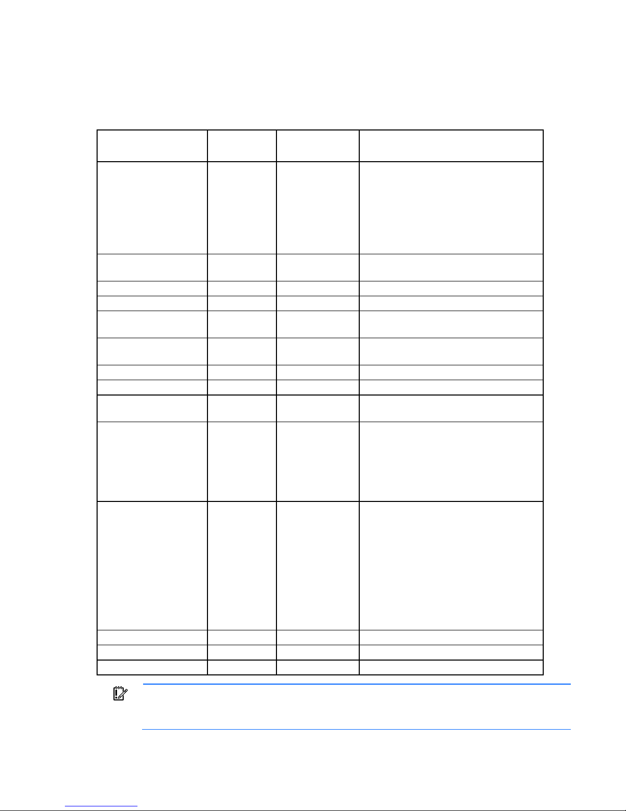
Systems Insight Display LED combinations
•
•
•
•
•
•
•
•
•
•
•
When the health LED on the front panel illuminates either amber or red, the server is experiencing a health
event. Combinations of illuminated Systems Insight Display LEDs, the system power LED, and the health LED
indicate system status.
Systems Insight Display
LED and color
Processor (amber)
Processor (amber)
DIMM (amber)
DIMM (amber)
Over temp (amber)
Over temp (amber)
PCI riser (amber)
Fan (amber)
Fan (amber)
Power supply (amber)
Power supply (amber)
Power cap (off)
Power cap (green)
Power cap (green)
IMPORTANT: If more than one DIMM slot LED is illuminated, further troubleshooting is required.
Test each bank of DIMMs by removing all other DIMMs. Isolate the failed DIMM by replacing
each DIMM in a bank with a known working DIMM.
Health LED System power
Status
LED
Red Amber One or more of the following conditions may
exist:
Processor in socket X has failed.
Processor X is not installed in the socket.
Processor X is unsupported.
ROM detects a failed processor during
POST.
Amber Green Processor in socket X is in a pre-failure
condition.
Red Green One or more DIMMs have failed.
Amber Green DIMM in slot X is in a pre-failure condition.
Amber Green The Health Driver has detected a cautionary
temperature level.
Red Amber The server has detected a hardware critical
temperature level.
Red Green The PCI riser cage is not seated properly.
Amber Green One fan has failed or has been removed.
Red Green Two or more fans have failed or been
removed.
Red Amber One or more of the following conditions may
exist:
Only one power supply is installed and
that power supply is in standby.
Power supply fault
System board fault
Amber Green One or more of the following conditions may
exist:
Redundant power supply is installed and
only one power supply is functional.
AC power cord is not plugged into
redundant power supply.
Redundant power supply fault
Power supply mismatch at POST or
power supply mismatch through hot-plug
addition
— Amber Standby
— Flashing green Waiting for power
— Green Power is available.
Component identification 16
Device numbers
• 4 LFF configuration
• 8 SFF configuration
• 10 SFF configuration
IMPORTANT: A cache module is required for a 10 SFF drive cage. Drives installed in a 10 SFF
configuration do not function without a cache module.
For more information, see "Installing the cache module (on page 53)".
Component identification 17
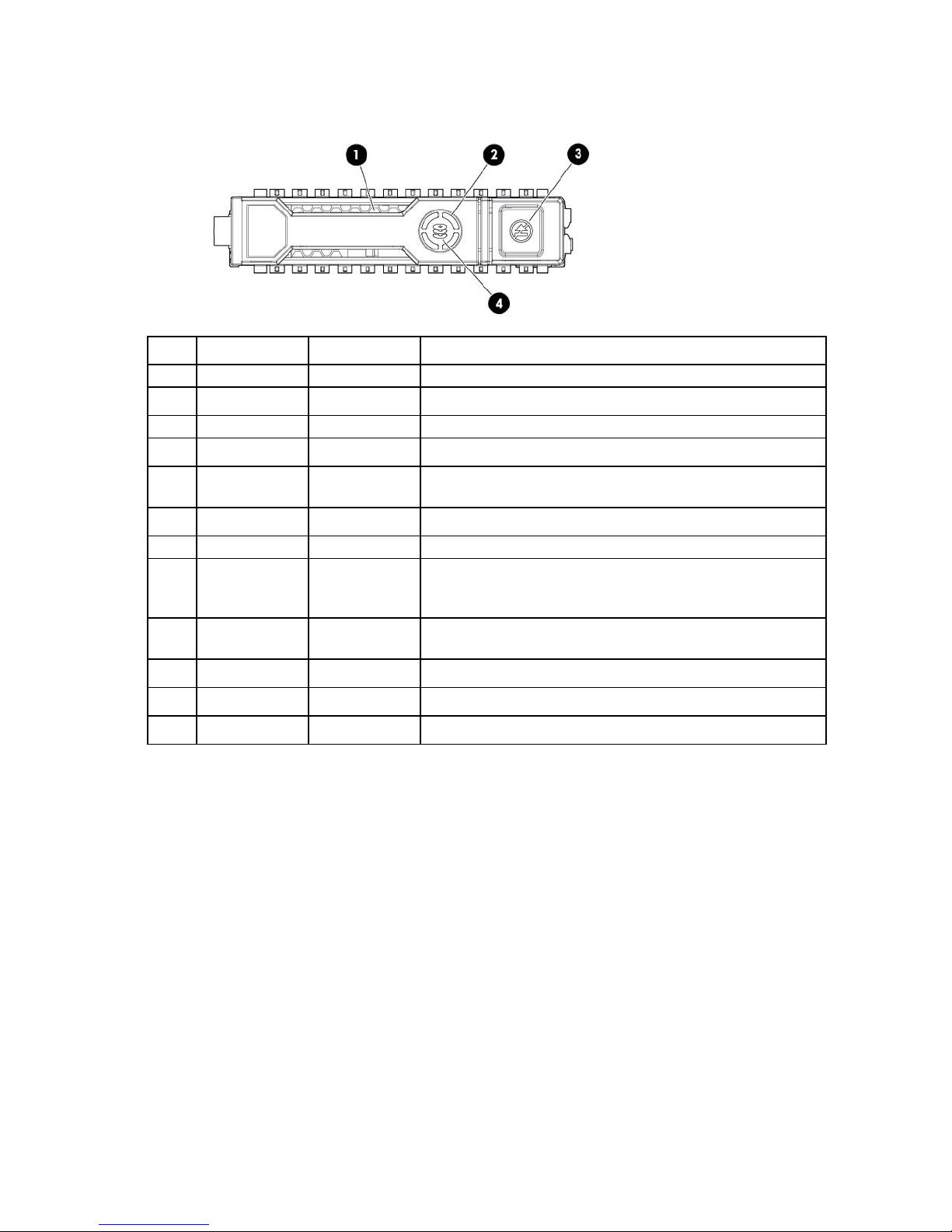
Drive LED definitions
Item LED Status Definition
1
2
3
4
Locate Solid blue The drive is being identified by a host application.
Flashing blue The drive carrier firmware is being updated or requires an update.
Activity ring Rotating green Drive activity
Off No drive activity
Do not remove Solid white Do not remove the drive. Removing the drive causes one or more of
the logical drives to fail.
Off Removing the drive does not cause a logical drive to fail.
Drive status Solid green The drive is a member of one or more logical drives.
Flashing green The drive is rebuilding or performing a RAID migration, stripe size
migration, capacity expansion, or logical drive extension, or is
erasing.
Flashing
amber/green
Flashing amber The drive is not configured and predicts the drive will fail.
Solid amber The drive has failed.
Off The drive is not configured by a RAID controller.
The drive is a member of one or more logical drives and predicts
the drive will fail.
Fan modules
• One-processor configuration
Component identification 18
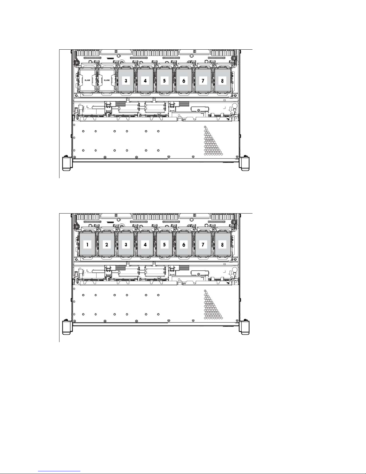
When only one processor is installed, be sure the fan blanks are always installed in bays 1 and 2 to
ensure proper cooling.
• Two-processor configuration
Install fans 1 and 2 only when processor 2 is installed. When only one processor is installed, always
install the fan blanks.
Component identification 19

Operations
Power up the server
To power up the server, press the Power On/Standby button.
Power down the server
Before powering down the server for any upgrade or maintenance procedures, perform a backup of critical
server data and programs.
IMPORTANT: When the server is in standby mode, auxiliary power is still being provided to the
To power down the server, use one of the following methods:
• Press and release the Power On/Standby button.
• Press and hold the Power On/Standby button for more than 4 seconds to force the server to enter
• Use a virtual power button selection through HP iLO.
system.
This method initiates a controlled shutdown of applications and the OS before the server enters standby
mode.
standby mode.
This method forces the server to enter standby mode without properly exiting applications and the OS.
If an application stops responding, you can use this method to force a shutdown.
This method initiates a controlled remote shutdown of applications and the OS before the server enters
standby mode.
Before proceeding, verify the server is in standby mode by observing that the system power LED is amber.
Extend the server from the rack
NOTE: If the optional cable management arm option is installed, you can extend the server
without powering down the server or disconnecting peripheral cables and power cords. These
1. Power down the server (on page 20).
2. Disconnect all peripheral cables and power cords.
3. Loosen the front panel thumbscrews.
4. Extend the server on the rack rails until the server rail-release latches engage.
steps are only necessary with the standard cable management solution.
WARNING: To reduce the risk of personal injury or equipment damage, be sure that the rack is
adequately stabilized before extending a component from the rack.
Operations 20
WARNING: To reduce the risk of personal injury, be careful when pressing the server rail-release
latches and sliding the server into the rack. The sliding rails could pinch your fingers.
5. After performing the installation or maintenance procedure, slide the server into the rack:
a. Slide the server fully into the rack.
b. Secure the server by tightening the thumbscrews.
6. Connect the peripheral cables and power cords.
Remove the server from the rack
To remove the server from an HP, Compaq branded, telco, or third-party rack:
1. Power down the server (on page 20).
2. Extend the server from the rack (on page 20).
3. Disconnect the cabling and remove the server from the rack. For more information, refer to the
documentation that ships with the rack mounting option.
4. Place the server on a sturdy, level surface.
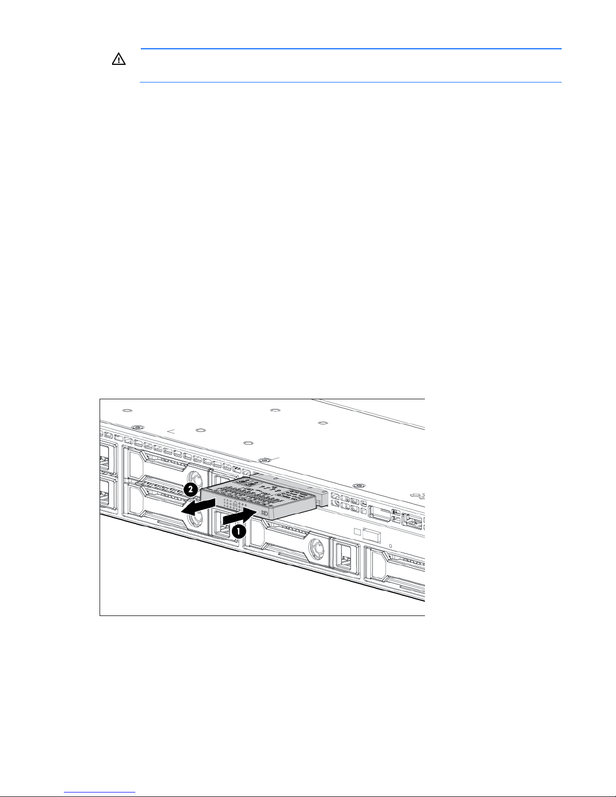
Access the HP Systems Insight Display
1. Press and release the display.
2. Extend the display from the chassis.
o 8 SFF configuration
Operations 21
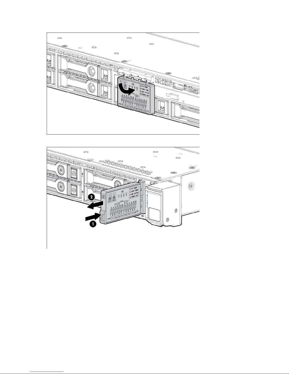
The display can be rotated up to 90 degrees.
o 10 SFF configuration
Operations 22
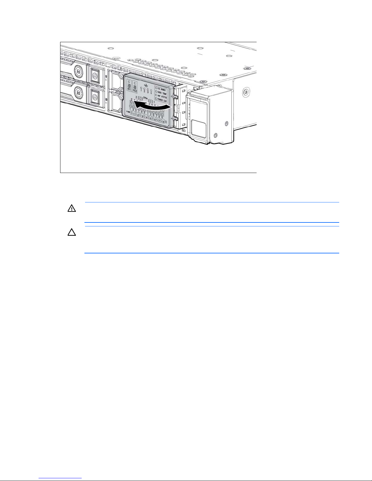
The display can be rotated up to 90 degrees.
Remove the access panel
WARNING: To reduce the risk of personal injury from hot surfaces, allow the drives and the
internal system components to cool before touching them.
CAUTION: Do not operate the server for long periods with the access panel open or removed.
Operating the server in this manner results in improper airflow and improper cooling that can
lead to thermal damage.
To remove the component:
1. Power down the server (on page 20).
2. Extend the server from the rack (on page 20).
3. Open the locking latch, slide the access panel to the rear of the chassis, and remove the access panel.
If the locking latch is locked use a T-15 Torx screwdriver to unlock the latch.
Install the access panel
1. Place the access panel on top of the server with the hood latch open. Allow the panel to extend past the
rear of the server approximately 1.25 cm (0.5 in).
2. Push down on the hood latch. The access panel slides to a closed position.
3. Use a T-15 Torx screwdriver to tighten the security screw on the hood latch.
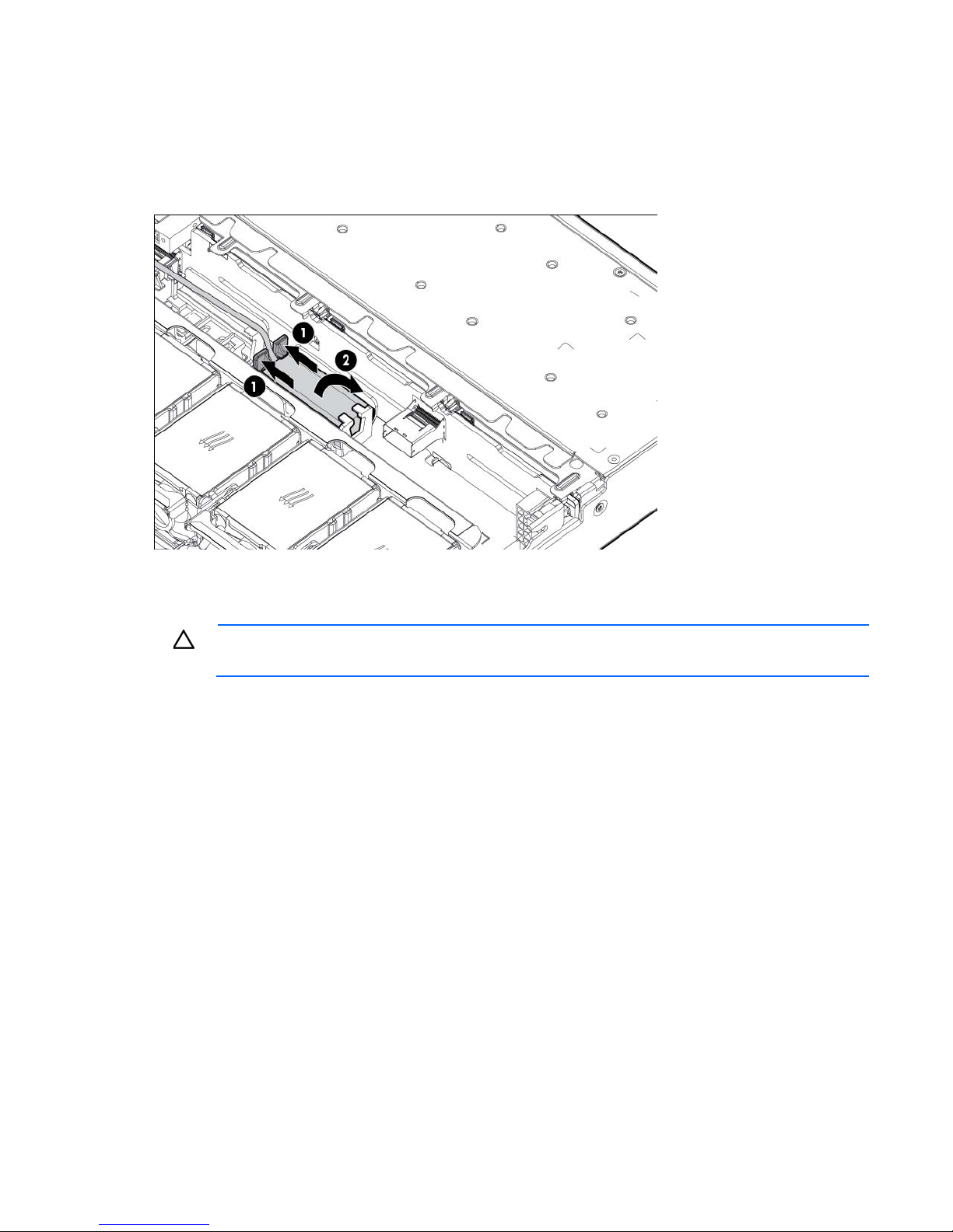
Remove the FBWC capacitor pack
1. Power down the server (on page 20).
2. Remove all power:
a. Disconnect each power cord from the power source.
Operations 23
b.
Disconnect each power cord from the server.
3. Extend the server from the rack (on page 20).
4. Remove the access panel (on page 23).
5. Disconnect the cable from the cache module or PCIe controller.
6. Remove the FBWC capacitor pack.
Remove the PCI riser cage
CAUTION: To prevent damage to the server or expansion boards, power down the server and
1. Power down the server (on page 20).
2. Remove all power:
3. Extend the server from the rack (on page 20).
4. Remove the access panel (on page 23).
5. Remove the PCI riser cage:
remove all AC power cords before removing or installing the PCI riser cage.
a. Disconnect each power cord from the power source.
b. Disconnect each power cord from the server.
a. Disconnect external cables connected to any existing expansion boards.
b. Disengage the two PCI riser cage thumbscrews. Lift the tab, rotate 180 degrees, and the
thumbscrew pops up.
Operations 24
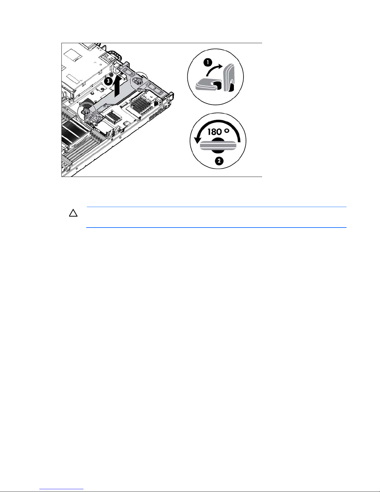
c.
Lift the assembly to unseat the PCI riser boards, and then remove the cage.
Install the PCI riser cage
CAUTION: To prevent damage to the server or expansion boards, power down the server and
1. Power down the server (on page 20).
2. Remove all power:
3. Extend the server from the rack (on page 20).
4. Remove the access panel (on page 23).
5. Align the PCI riser boards with the corresponding connectors on the system board, and then install the
6. Push down on the thumbscrew and rotate 180 degrees.
remove all AC power cords before removing or installing the PCI riser cage.
a. Disconnect each power cord from the power source.
b. Disconnect each power cord from the server.
cage.
Operations 25
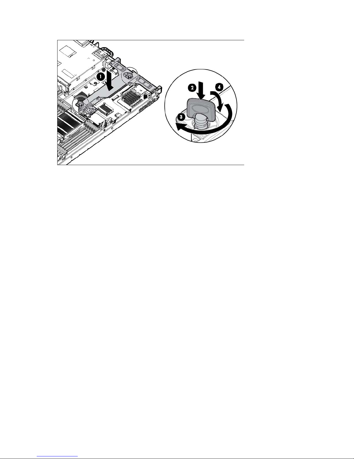
7.
Lower the tab.
8. Install the access panel (on page 23).
9. Slide the server into the rack.
10. Connect each power cord to the server.
11. Connect each power cord to the power source.
12. Power up the server (on page 20).
Operations 26

Setup
Optional installation services
Delivered by experienced, certified engineers, HP Care Pack services help you keep your servers up and
running with support packages tailored specifically for HP ProLiant systems. HP Care Packs let you integrate
both hardware and software support into a single package. A number of service level options are available
to meet your needs.
HP Care Pack Services offer upgraded service levels to expand your standard product warranty with
easy-to-buy, easy-to-use support packages that help you make the most of your server investments. Some of
the Care Pack services are:
• Hardware support
o 6-Hour Call-to-Repair
o 4-Hour 24x7 Same Day
o 4-Hour Same Business Day
• Software support
o Microsoft®
o Linux
o HP ProLiant Essentials (HP SIM and RDP)
o VMware
• Integrated hardware and software support
o Critical Service
o Proactive 24
o Support Plus
o Support Plus 24
• Startup and implementation services for both hardware and software
For more information on HP Care Pack Services, see the HP website
(http://www.hp.com/services/carepack).
Rack planning resources
The rack resource kit ships with all HP branded or Compaq branded 9000, 10000, and H9 series racks. For
more information on the content of each resource, see the rack resource kit documentation.
Optimum environment
When installing the server in a rack, select a location that meets the environmental standards described in
this section.
Setup 27
Space and airflow requirements
ensures proper airflow. Using a rack without blanking panels results in improper cooling that can
party rack is used, observe the following additional requirements to ensure
To allow for servicing and adequate airflow, observe the following space and airflow requirements when
deciding where to install a rack:
• Leave a minimum clearance of 63.5 cm (25 in) in front of the rack.
• Leave a minimum clearance of 76.2 cm (30 in) behind the rack.
• Leave a minimum clearance of 121.9 cm (48 in) from the back of the rack to the back of another rack
or row of racks.
HP servers draw in cool air through the front and expel warm air through the rear. Therefore, the front and
rear rack doors must be adequately ventilated to allow ambient room air to enter the cabinet, and the rear
door must be adequately ventilated to allow the warm air to escape from the cabinet.
CAUTION: To prevent improper cooling and damage to the equipment, do not block the
When vertical space in the rack is not filled by a server or rack component, the gaps between the
components cause changes in airflow through the rack and across the servers. Cover all gaps with blanking
panels to maintain proper airflow.
ventilation openings.
CAUTION: Always use blanking panels to fill empty vertical spaces in the rack. This arrangement
lead to thermal damage.
The 9000 and 10000 Series Racks provide proper server cooling from flow-through perforations in the front
and rear doors that provide 64 percent open area for ventilation.
CAUTION: When using a Compaq branded 7000 series rack, install the high airflow rack door
insert (PN 327281-B21 for 42U rack, PN 157847-B21 for 22U rack) to provide proper
front-to-back airflow and cooling.
CAUTION: If a third-
adequate airflow and to prevent damage to the equipment:
• Front and rear doors—If the 42U rack includes closing front and rear doors, you must allow
5,350 sq cm (830 sq in) of holes evenly distributed from top to bottom to permit adequate
airflow (equivalent to the required 64 percent open area for ventilation).
• Side—The clearance between the installed rack component and the side panels of the rack
must be a minimum of 7 cm (2.75 in).
Temperature requirements
To ensure continued safe and reliable equipment operation, install or position the system in a well-ventilated,
climate-controlled environment.
The maximum recommended ambient operating temperature (TMRA) for most server products is 35°C
(95°F). The temperature in the room where the rack is located must not exceed 35°C (95°F).
CAUTION: To reduce the risk of damage to the equipment when installing third-party options:
• Do not permit optional equipment to impede airflow around the server or to increase the
internal rack temperature beyond the maximum allowable limits.
• Do not exceed the manufacturer’s TMRA.
Setup 28

Power requirements
Installation of this equipment must comply with local and regional electrical regulations governing the
installation of information technology equipment by licensed electricians. This equipment is designed to
operate in installations covered by NFPA 70, 1999 Edition (National Electric Code) and NFPA-75, 1992
(code for Protection of Electronic Computer/Data Processing Equipment). For electrical power ratings on
options, refer to the product rating label or the user documentation supplied with that option.
WARNING: To reduce the risk of personal injury, fire, or damage to the equipment, do not
overload the AC supply branch circuit that provides power to the rack. Consult the electrical
When installing more than one server, you might need to use additional power distribution devices to safely
provide power to all devices. Observe the following guidelines:
• Balance the server power load between available AC supply branch circuits.
• Do not allow the overall system AC current load to exceed 80% of the branch circuit AC current rating.
authority having jurisdiction over wiring and installation requirements of your facility.
CAUTION: Protect the server from power fluctuations and temporary interruptions with a
regulating uninterruptible power supply. This device protects the hardware from damage caused
by power surges and voltage spikes and keeps the system in operation during a power failure.
• Do not use common power outlet strips for this equipment.
• Provide a separate electrical circuit for the server.
For more information on the hot-plug power supply and calculators to determine server power consumption
in various system configurations, see the HP Power Advisor website
(http://www.hp.com/go/hppoweradvisor).
Electrical grounding requirements
The server must be grounded properly for proper operation and safety. In the United States, you must install
the equipment in accordance with NFPA 70, 1999 Edition (National Electric Code), Article 250, as well as
any local and regional building codes. In Canada, you must install the equipment in accordance with
Canadian Standards Association, CSA C22.1, Canadian Electrical Code. In all other countries, you must
install the equipment in accordance with any regional or national electrical wiring codes, such as the
International Electrotechnical Commission (IEC) Code 364, parts 1 through 7. Furthermore, you must be sure
that all power distribution devices used in the installation, such as branch wiring and receptacles, are listed
or certified grounding-type devices.
Because of the high ground-leakage currents associated with multiple servers connected to the same power
source, HP recommends the use of a PDU that is either permanently wired to the building’s branch circuit or
includes a nondetachable cord that is wired to an industrial-style plug. NEMA locking-style plugs or those
complying with IEC 60309 are considered suitable for this purpose. Using common power outlet strips for
the server is not recommended.
Connecting a DC power cable to a DC power source
Setup 29
WARNING: To reduce the risk of electric shock or energy hazards:
• This equipment must be installed by trained service personnel, as defined by the NEC and IEC
60950-1, Second Edition, the standard for Safety of Information Technology Equipment.
• Connect the equipment to a reliably grounded SELV source. An SELV source is a secondary
circuit that is designed so normal and single fault conditions do not cause the voltages to
exceed a safe level (60 V direct current).
• The branch circuit overcurrent protection must be rated 20A.
WARNING: When installing a DC power supply, the ground wire must be connected before the
positive or negative leads.
WARNING: Remove power from the power supply before performing any installation steps or
maintenance on the power supply.
CAUTION: The server equipment connects the earthed conductor of the DC supply circuit to the
earthing conductor at the equipment. For more information, see the HP 750W Common Slot -48V
DC Input Hot-Plug Power Supply Kit Installation Instructions.
CAUTION: If the DC connection exists between the earthed conductor of the DC supply circuit and
the earthing conductor at the server equipment, the following conditions must be met:
• This equipment must be connected directly to the DC supply system earthing electrode
conductor or to a bonding jumper from an earthing terminal bar or bus to which the DC supply
system earthing electrode conductor is connected.
• This equipment should be located in the same immediate area (such as adjacent cabinets) as
any other equipment that has a connection between the earthed conductor of the same DC
supply circuit and the earthing conductor, and also the point of earthing of the DC system. The
DC system should be earthed elsewhere.
• The DC supply source is to be located within the same premises as the equipment.
• Switching or disconnecting devices should not be in the earthed circuit conductor between the
DC source and the point of connection of the earthing electrode conductor.
To connect a DC power cable to a DC power source:
1. Cut the DC power cord ends no shorter than 150 cm (59.06 in).
2. If the power source requires ring tongues, use a crimping tool to install the ring tongues on the power
cord wires.
IMPORTANT: The ring tongues must be UL approved and accommodate 12 gauge wires.
IMPORTANT: The minimum nominal thread diameter of a pillar or stud type terminal must be 3.5
mm (0.138 in); the diameter of a screw type terminal must be 4.0 mm (0.157 in).
3. Stack each same-colored pair of wires and then attach them to the same power source. The power cord
consists of three wires (black, red, and green).
For more information, see the HP 750W Common Slot -48V DC Input Hot-Plug Power Supply Installation
Instructions.
Rack warnings
Setup 30
 Loading...