

HP ProLiant DL360 Gen9 Maintenance And Service Manual

HPE ProLiant DL360 Gen9 Server
Abstract
This guide describes identification and maintenance procedures, diagnostic tools, specifications, and requirements for hardware
Part Number: 767928-006
March 2
Edition: 6
Maintenance and Service Guide
components and software. This guide is for an experienced service technician. Hewlett Packard Enterprise assumes you are qualified in the
servicing of computer equipment, trained in recognizing hazards in products, and are familiar with weight and stability precautions.
016

© Copyright 2014, 2016 Hewlett Packard Enterprise Development LP
The information contained herein is subject to change without notice. The only warranties for Hewlett Packard Enterprise products and services
are set forth in the express warranty statements accompanying such products and services. Nothing herein should be construed as constituting
an additional warranty. Hewlett Packard Enterprise shall not be liable for technical or editorial errors or omissions contained herein.
Links to third-party websites take you outside the Hewlett Packard Enterprise website. Hewlett Packard Enterprise has no control over and is not
responsible for information outside the Hewlett Packard Enterprise website.
Microsoft® and Windows® are either registered trademarks or trademarks of Microsoft Corporation in the United States and/or other countries.
Intel®, Pentium®, and Itanium® are trademarks of Intel Corporation in the U.S. and other countries.
microSD is a trademark or registered trademark of SD-3C in the United States, other countries or both.
UNIX® is a registered trademark of The Open Group.
NVIDIA® is a trademark of NVIDIA Corporation in the U.S. and other countries.

Contents
Illustrated parts catalog ............................................................................................................................. 5
Mechanical components ........................................................................................................................................... 5
System components ................................................................................................................................................. 8
Removal and replacement procedures ................................................................................................... 16
Required tools ........................................................................................................................................................ 16
Preparation procedures .......................................................................................................................................... 16
Power down the server ................................................................................................................................ 16
Extend the server from the rack .................................................................................................................. 17
Remove the server from the rack ................................................................................................................ 17
Access the product rear panel ..................................................................................................................... 18
Access the Systems Insight Display ............................................................................................................ 18
Safety considerations ............................................................................................................................................. 20
Preventing electrostatic discharge............................................................................................................... 20
Symbols on equipment ................................................................................................................................ 21
Server warnings and cautions ..................................................................................................................... 21
Drive blank ............................................................................................................................................................. 22
Hot-plug SAS/SATA drives and SSDs ................................................................................................................... 22
NVMe drives ........................................................................................................................................................... 22
Power supply blank ................................................................................................................................................ 24
AC power supply .................................................................................................................................................... 24
HPE 750W Flex Slot Hot Plug Battery Backup Module .......................................................................................... 25
Access panel .......................................................................................................................................................... 26
Primary PCI riser cage ........................................................................................................................................... 26
PCIe riser board ..................................................................................................................................................... 27
Secondary PCI riser cage ...................................................................................................................................... 28
Primary PCIe riser blank ........................................................................................................................................ 29
Secondary PCIe riser blank .................................................................................................................................... 30
GPU riser and cable option .................................................................................................................................... 31
Fan module ............................................................................................................................................................ 32
Fan blank ................................................................................................................................................................ 33
8SFF Optical/USB/VGA assembly ......................................................................................................................... 34
4LFF Optical/USB/VGA assembly .......................................................................................................................... 35
8SFF Systems Insight Display ............................................................................................................................... 37
4LFF Systems Insight Display ................................................................................................................................ 38
Location discovery services ear ............................................................................................................................. 39
2SFF SAS/SATA drive cage assembly option ....................................................................................................... 41
2SFF Express Bay drive backplane ....................................................................................................................... 44
4LFF hard drive backplane ..................................................................................................................................... 46
8SFF hard drive backplane .................................................................................................................................... 47
10SFF (6 NVMe + 4 SAS/SATA) Express Bay drive backplane ............................................................................ 48
FlexibleLOM ........................................................................................................................................................... 49
Smart Storage Battery ............................................................................................................................................ 50
Expansion boards ................................................................................................................................................... 51
M.2 SSD enablement board ................................................................................................................................... 52
DIMMs .................................................................................................................................................................... 53
Heatsink ................................................................................................................................................................. 54
High-performance heatsink .................................................................................................................................... 55
Processor ............................................................................................................................................................... 56
System battery ....................................................................................................................................................... 59
System board ......................................................................................................................................................... 60
HP Trusted Platform Module .................................................................................................................................. 65
Troubleshooting ...................................................................................................................................... 67
Troubleshooting resources ..................................................................................................................................... 67
Contents 3

Diagnostic tools ...................................................................................................................................... 68
Product QuickSpecs ............................................................................................................................................... 68
Active Health System ............................................................................................................................................. 68
HPE iLO ................................................................................................................................................................. 69
HPE ProLiant Pre-boot Health Summary .................................................................................................... 69
Integrated Management Log ....................................................................................................................... 70
Component identification ........................................................................................................................ 71
Front panel components ......................................................................................................................................... 71
Front panel LEDs and buttons ................................................................................................................................ 72
UID button functionality ............................................................................................................................... 73
Power fault LEDs ......................................................................................................................................... 74
Systems Insight Display LEDs ............................................................................................................................... 74
Systems Insight Display LED combinations ........................................................................................................... 75
Rear panel components ......................................................................................................................................... 76
Rear panel LEDs and buttons ................................................................................................................................ 77
Flex slot battery backup module LEDs and buttons ............................................................................................... 78
System board components ..................................................................................................................................... 79
System maintenance switch ........................................................................................................................ 80
NMI jumper .................................................................................................................................................. 80
DIMM slots................................................................................................................................................... 81
Non-hot-plug PCI riser board slot definitions ............................................................................................... 81
Device numbers ..................................................................................................................................................... 82
Hot-plug drive LED definitions ..................................................................................................................... 83
NVMe SSD components.............................................................................................................................. 83
Hot-plug fans .......................................................................................................................................................... 84
Cabling .................................................................................................................................................... 86
Cabling overview .................................................................................................................................................... 86
2SFF embedded SATA backplane cabling ............................................................................................................ 86
4LFF Universal Media Bay cabling ......................................................................................................................... 87
8SFF Universal Media Bay cabling ........................................................................................................................ 88
10SFF (6 NVMe + 4 SAS/SATA) Express Bay Enablement Option cabling .......................................................... 89
Smart Array controller cabling ................................................................................................................................ 90
Embedded SATA cabling ....................................................................................................................................... 91
M.2 SSD Enablement Board option cabling ........................................................................................................... 92
GPU cabling ........................................................................................................................................................... 93
Specifications .......................................................................................................................................... 94
Environmental specifications .................................................................................................................................. 94
Server specifications .............................................................................................................................................. 94
Power supply specifications ................................................................................................................................... 95
HPE 500W Flex Slot Platinum Hot-plug Power Supply ............................................................................... 95
HPE 800W Flex Slot Platinum Hot-plug Power Supply ............................................................................... 96
HPE 800W Flex Slot Titanium Plus Hot-plug Power Supply ....................................................................... 96
HPE 800W Flex Slot Universal Hot-plug Power Supply .............................................................................. 97
HPE 800W Flex Slot -48VDC Hot-plug Power Supply ................................................................................ 97
HPE 1400W Flex Slot Platinum Plus Hot-plug Power Supply ..................................................................... 98
HPE 750W Flex Slot Hot-plug Battery Backup Module .......................................................................................... 99
Hot-plug power supply calculations ........................................................................................................................ 99
Acronyms and abbreviations................................................................................................................. 100
Documentation feedback ...................................................................................................................... 103
Index ..................................................................................................................................................... 104
Contents 4
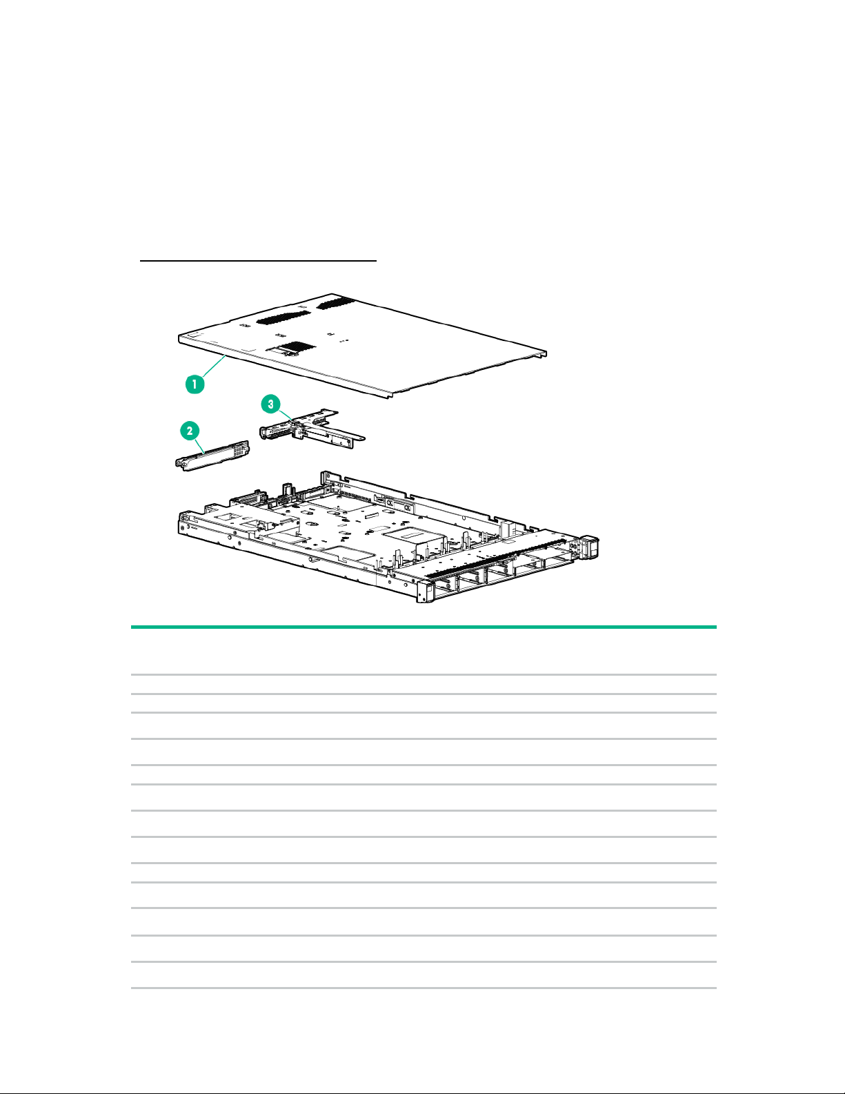
Illustrated parts catalog
1
Access panel
775425-001
Mandatory1
2
PCI riser blank
—
—
a) PCI riser blank, full height
775431-001
Mandatory1
b) PCI riser blank, low profile
785499-001
Mandatory1
3
PCI riser cage
—
—
a) PCI riser cage, standard primary
775421-001
Optional2
b) PCI riser cage, secondary, full height*
775419-001
Optional2
c) PCI riser cage, secondary, low profile*
775420-001
Optional2
4
Miscellaneous blanks kit*
775423-001
a) Power supply blank
—
Mandatory1
b) Heatsink blank
—
Mandatory1
c) Fan blank
—
Mandatory1
d) FlexibleLOM blank
—
Mandatory1
Mechanical components
Hewlett Packard Enterprise continually improves and changes product parts. For complete and current
supported parts information, see the Hewlett Packard Enterprise PartSurfer website
(http://www.hpe.com/info/partssurfer).
Item Description
Spare part
number
Customer
self repair
Illustrated parts catalog 5

5
Standard right ear
775417-001
Mandatory1
6
Standard left ear
795214-001
Mandatory1
Rack mounting hardware
—
—
7
Rack mounting hardware kit*
—
—
a) SFF Easy Install Rail
744111-001
Mandatory1
b) LFF Easy Install Rail
744112-001
Mandatory1
c) SFF Ball Bearing Rail
675042-001
Mandatory1
d) LFF Ball Bearing Rail
675041-001
Mandatory1
8
Cable management arm*
—
—
a) Cable management arm, easy install
744113-001
Mandatory1
b) Cable management arm, ball bearing
675043-001
Mandatory1
Item Description
Spare part
number
Customer
self repair
*Not shown
1
Mandatory—Parts for which customer self repair is mandatory. If you request Hewlett Packard Enterprise to replace
these parts, you will be charged for the travel and labor costs of this service.
2
Optional—Parts for which customer self repair is optional. These parts are also designed for customer self repair. If,
however, you require that Hewlett Packard Enterprise replace them for you, there may or may not be additional
charges, depending on the type of warranty service designated for your product.
3
No—Some Hewlett Packard Enterprise parts are not designed for customer self repair. In order to satisfy the
customer warranty, Hewlett Packard Enterprise requires that an authorized service provider replace the part. These
parts are identified as "No" in the Illustrated Parts Catalog.
1
Obligatoire—Pièces pour lesquelles le client doit procéder lui-même aux réparations. Si vous demandez à Hewlett
Packard Enterprise de procéder au remplacement de ces pièces, les frais de transport et de main d’œuvre pour ce
service vous seront facturés.
2
Facultatif—Pièces pour lesquelles une réparation par le client est facultative. Ces pièces sont également conçues
pour que le client puisse procéder lui-même aux réparations. Cependant, les frais supplémentaires engendrés par le
remplacement de ces pièces par Hewlett Packard Enterprise dépendent du type de service de garantie désigné pour
votre produit.
3
Non—Certaines pièces Hewlett Packard Enterprise ne sont pas conçues pour être remplacées par le client. Afin de
se conformer aux exigences de la garantie la garantie du client, Hewlett Packard Enterprise demande à un
fournisseur de services agréé de procéder au remplacement de la pièce. Ces pièces sont signaléespar le mot « Non
» dans le Catalogue de pièces illustré.
1
Obbligatorio—Parti per le quali il cliente è tenuto a effettuare autonomamente la riparazione. Se si richiede
l'intervento di Hewlett Packard Enterprise per la sostituzione di queste parti, al cliente verranno addebitate le spese di
viaggio e manodopera dell'operazione.
2
Facoltativo—Parti per le quali la riparazione in autonomia da parte del cliente è facoltativa. Queste parti sono
progettate per consentire anche la riparazione da parte del cliente. Tuttavia, se il cliente richiedel'intervento di Hewlett
Packard Enterprise per la sostituzione, potrebbero essere addebitate spese aggiuntive a seconda del tipo di garanzia
in assistenza previsto per il prodotto.
3
No—Alcune parti Hewlett Packard Enterprise non sono progettate la riparazione in autonomia da parte del cliente. In
base a quanto previsto dalla garanzia per il cliente, Hewlett Packard Enterprise richiede l'intervento di un tecnico
autorizzato per la sostituzione della parte. Queste parti sono contrassegnate con"No"nel catalogo parti illustrato.
1
Zwingend—Teile, für die das Customer Self Repair-Verfahren zwingend vorgegeben ist. Wenn Sie den Austausch
dieser Teile von Hewlett Packard Enterprisevornehmen lassen, werden Ihnen die Anfahrt- und Arbeitskosten für
diesen Service berechnet.
2
Optional—Teile, für die das Customer Self Repair-Verfahren optional ist. Diese Teile sind auch für Customer Self
Repair ausgelegt. Wenn Sie jedoch den Austausch dieser Teile von Hewlett Packard Enterprisevornehmen lassen
möchten, können bei diesem Service je nach den für Ihr Produkt vorgesehenen Garantiebedingungen zusätzliche
Kosten anfallen.
Illustrated parts catalog 6
3
Nein—Einige Hewlett Packard Enterprise Teile sind nicht für Customer Self Repair ausgelegt. Um den
Garantieanspruch des Kunden zu erfüllen, muss das Teil von einem Hewlett Packard Enterprise Servicepartner
ersetzt werden. Im illustrierten Teilekatalog sind diese Teile mit „No“ bzw. „Nein“ gekennzeichnet.
1
Obligatorio—Componentes cuya reparación por parte del usuario es obligatoria. Si solicita a Hewlett Packard
Enterprise que realice la sustitución de estos componentes, tendrá que hacerse cargo de los gastos de
desplazamiento y de mano de obra de dicho servicio.
2
Opcional—Componentes cuya reparación por parte del usuario es opcional. Estos componentes también están
diseñados para que puedan ser reparados por el usuario. Sin embargo, si precisa que Hewlett Packard Enterprise
realice su sustitución, puede o no conllevar costes adicionales, dependiendo del tipo de servicio de garantía
correspondiente al producto.
3
No—Algunos componentes de Hewlett Packard Enterprise no están diseñados para que puedan ser reparados por
el usuario. Para que el usuario haga valer su garantía, Hewlett Packard Enterprise pone como condición que un
proveedor de servicios autorizado realice la sustitución de estos componentes. Dichos componentes se identifican
con la palabra "No" en el catálogo ilustrado de componentes.
1
Verplicht—Onderdelen die de klant zelf moet vervangen. Als u Hewlett Packard Enterprise vraagt deze onderdelen
te vervangen, worden er reis- en arbeidskosten voor deze service in rekening gebracht.
2
Optioneel—Onderdelen die de klant zelf kan vervangen. Deze onderdelen zijn ook ontworpen om door de klant zelf
te worden vervangen. Als u Hewlett Packard Enterprise verzoekt om deze te vervangen, kan het zijn dat hiervoor
extra kosten in rekening worden gebracht, afhankelijk van het soort garantie dat op uw product van toepassing is.
3
Geen—Sommige onderdelen van Hewlett Packard Enterprise zijn niet ontworpen om door de klant zelf te worden
vervangen. Om te voldoen aan de garantievoorwaarden eist Hewlett Packard Enterprise dat een geautoriseerde
serviceverlener het onderdeel vervangt. Deze onderdelen worden aangeduid met 'Geen' in de geïllustreerde
onderdelencatalogus.
1
Obrigatório—Peças cujo reparo feito pelo cliente é obrigatório. Se desejar que a Hewlett Packard Enterprise
substitua essas peças, serão cobradas as despesas de transporte e mão-de-obra do serviço.
2
Opcional—Peças cujo reparo feito pelo cliente é opcional. Essas peças também são projetadas para o reparo feito
pelo cliente. No entanto, se desejar que a Hewlett Packard Enterprise as substitua, pode haver ou não a cobrança de
taxa adicional, dependendo do tipo de serviço de garantia destinado ao produto.
3
Não—Algumas peças da Hewlett Packard Enterprise não são projetadas para o reparo feito pelo cliente. A fim de
cumprir a garantia do cliente, a Hewlett Packard Enterprise exige que um técnico autorizado substitua a peça. Essas
peças estão identificadas com a marca "No" (Não), no catálogo de peças ilustrado.
Illustrated parts catalog 7
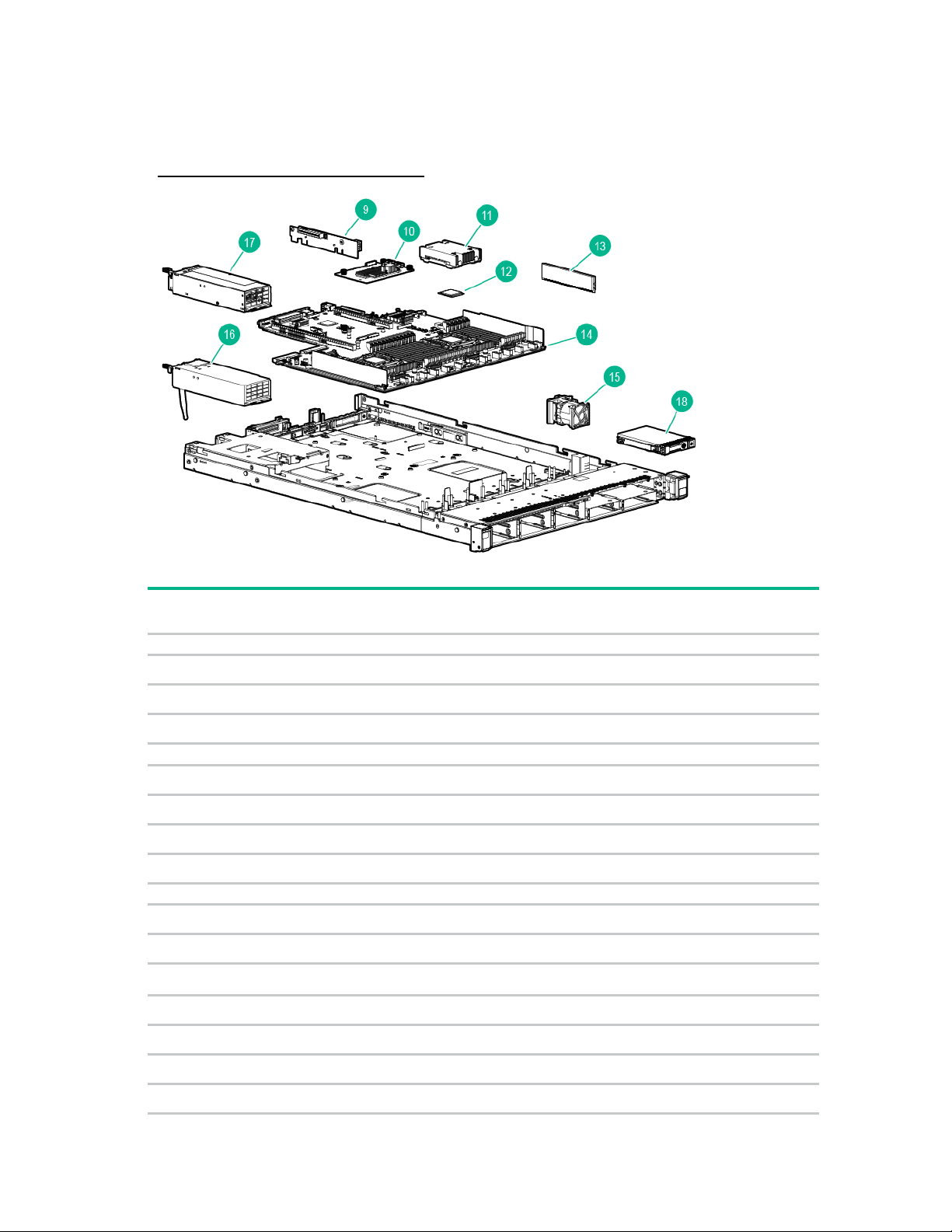
System components
number
self repair
9
PCIe riser boards
—
—
a) Primary PCIe riser board
785497-001
Optional2
b) Low-profile Secondary PCIe riser board*
785498-001
Optional2
c) Full-height Secondary PCIe riser board*
775419-001
Optional2
10
Controller options
—
—
a) HPE Smart Array P440ar Controller
775413-001
Mandatory1
b) HPE Smart Array P440ar Controller with cut heatsink*
786760-001
Mandatory1
c) HPE H240ar Smart Host Bus Adapter*
749997-001
Mandatory1
d) HPE Smart Array P840ar Controller*
848147-001
Mandatory1
11
Heatsink
—
—
a) Standard efficiency heatsink
775403-001
Optional2
b) High-performance heatsink*
775404-001
Optional2
Processor
—
—
a) 1.90-GHz Intel Xeon E5-2609 v3 processor* **
762443-001
Optional2
b) 2.40-GHz Intel Xeon E5-2620 v3 processor* **
762445-001
Optional2
c) 2.60-GHz Intel Xeon E5-2640 v3 processor* **
762447-001
Optional2
d) 2.60-GHz Intel Xeon E5-2660 v3 processor* **
762449-001
Optional2
Hewlett Packard Enterprise continually improves and changes product parts. For complete and current
supported parts information, see the Hewlett Packard Enterprise PartSurfer website
(http://www.hpe.com/info/partssurfer).
Item Description
12
Spare part
Customer
Illustrated parts catalog 8

number
self repair
e) 2.30-GHz Intel Xeon E5-2670 v3 processor* **
762450-001
Optional2
f) 2.50-GHz Intel Xeon E5-2680 v3 processor* **
762451-001
Optional2
g) 2.60-GHz Intel Xeon E5-2690 v3 processor
762452-001
Optional2
h) 2.00-GHz Intel Xeon E5-2683 v3 processor* **
762453-001
Optional2
i) 2.30-GHz Intel Xeon E5-2695 v3 processor* **
762454-001
Optional2
j) 3.50-GHz Intel Xeon E5-2637 v3 processor* **
762455-001
Optional2
k) 3.40-GHz Intel Xeon E5-2643 v3 processor* **
762456-001
Optional2
l) 3.20-GHz Intel Xeon E5-2667 v3 processor* **
762457-001
Optional2
m) 3.10-GHz Intel Xeon E5-2687W v3 processor* **
762458-001
Optional2
n) 1.80-GHz Intel Xeon E5-2630L v3 processor* **
762459-001
Optional2
o) 2.60-GHz Intel Xeon E5-2697 v3 processor* **
765154-001
Optional2
p) 2.30-GHz Intel Xeon E5-2698 v3 processor* **
780760-001
Optional2
q) 2.30-GHz Intel Xeon E5-2699 v3 processor* **
780761-001
Optional2
r) 3.00-GHz Intel Xeon E5-2623v3 processor* **
780762-001
Optional2
s) 1.70-GHz Intel Xeon E5-2603 v4 processor**
835599-001
Optional2
t) 1.70-GHz Intel Xeon E5-2609 v4 processor* **
835600-001
Optional2
u) 2.40-GHz Intel Xeon E5-2620 v4 processor* **
835601-001
Optional2
v) 2.20-GHz Intel Xeon E5-2630 v4 processor* **
835602-001
Optional2
w) 2.40-GHz Intel Xeon E5-2640 v4 processor* **
835603-001
Optional2
x) 2.20-GHz Intel Xeon E5-2650 v4 processor* **
835604-001
Optional2
y) 2.00-GHz Intel Xeon E5-2660 v4 processor* **
835605-001
Optional2
z) 2.40-GHz Intel Xeon E5-2680 v4 processor* **
835606-001
Optional2
aa) 2.60-GHz Intel Xeon E5-2690 v4 processor* **
835607-001
Optional2
bb) 1.80-GHz Intel Xeon E5-2630L v4 processor* **
835608-001
Optional2
cc) 1.70-GHz Intel Xeon E5-2650L v4 processor* **
835609-001
Optional2
dd) 2.60-GHz Intel Xeon E5-2623 v4 processor* **
835610-001
Optional2
ee) 3.40-GHz Intel Xeon E5-2637 v4 processor* **
835611-001
Optional2
ff) 3.20-GHz Intel Xeon E5-2643 v4 processor* **
835612-001
Optional2
gg) 2.90-GHz Intel Xeon E5-2667 v4 processor* **
835613-001
Optional2
hh) 2.10-GHz Intel Xeon E5-2683 v4 processor* **
835614-001
Optional2
ii) 2.10-GHz Intel Xeon E5-2695 v4 processor* **
835615-001
Optional2
jj) 2.30-GHz Intel Xeon E5-2697 v4 processor* **
835616-001
Optional2
ll) 3.00-GHz Intel Xeon E5-2687W v4 processor* **
841034-001
Optional2
Item Description
Spare part
Customer
Illustrated parts catalog 9

number
self repair
13
DIMM
—
—
a) 8-GB, 1Rx4, PC4-2133R
774170-001
Mandatory1
b) 8-GB, 2Rx8, PC4-2133R*
774171-001
Mandatory1
c) 16-GB, 2Rx4, PC4-2133R*
774172-001
Mandatory1
d) 16-GB, 2Rx4, PC4-2133L*
774173-001
Mandatory1
e) 32-GB, 4Rx4, PC4-2133L*
774174-001
Mandatory1
f) 8-GB, 1Gx8, PC4-2400R*
852545-001
Mandatory1
g) 8-GB, 1Gx8, PC4-2400R*
819410-001
Mandatory1
h) 16-GB, 1Gx4, PC4-2400R*
846740-001
Mandatory1
i) 16-GB, 2Gx4, PC4-2400R*
819411-001
Mandatory1
j) 32-GB, 2Gx4, PC4-2400R*
819412-001
Mandatory1
k) 64-GB, 2Gx4, PC4-2400L*
819413-001
Mandatory1
l) 32-GB, 2Gx4, PC4-2400L*
819414-001
Mandatory1
14
System board assembly
—
—
a) System board assembly
775400-001
Optional2
b) System board assembly- BRDWL
843307-001
Optional2
15
Hot plug fans
—
—
a) Standard fan module
775415-001
Mandatory1
b) High-efficiency fan module*
775416-001
Mandatory1
Hot-plug power supplies
—
—
a) 500 W, Flex Slot Platinum
754377-001
Mandatory1
b) 800 W, Flex Slot Platinum*
754381-001
Mandatory1
c) 800 W, Flex Slot Titanium*
754378-001
Mandatory1
d) 800 W, Flex Slot Universal*
754379-001
Mandatory1
e) 800 W, Flex Slot –48Vdc*
754382-001
Mandatory1
f) 1400 W, Flex Slot Platinum*
754383-001
Mandatory1
17
HPE 750W Flex Slot Hot-Plug Battery Backup Module
754380-001
Mandatory1
18
Hot-plug drives
—
—
a) 146-GB, SAS, SFF, 15,000-rpm, 6G
653950-001
Mandatory1
b) 300-GB, SAS, SFF, 10,000-rpm, 6G*
653955-001
Mandatory1
c) 450-GB, SAS, SFF, 10,000-rpm, 6G*
653956-001
Mandatory1
d) 500-GB, SAS, SFF, 7,200-rpm, 6G*
653953-001
Mandatory1
e) 600-GB, SAS, SFF, 10,000-rpm, 6G*
653957-001
Mandatory1
f) 900-GB, SAS, SFF, 10,000-rpm, 6G*
653971-001
Mandatory1
g) 1-TB, SAS, SFF, 7,200-rpm, 6G*
653954-001
Mandatory1
Item Description
Spare part
Customer
16
Illustrated parts catalog 10

number
self repair
h) 1-TB, SAS, LFF, 7,200-rpm, 6G*
653947-001
Mandatory1
i) 1.2-TB, SAS, SFF, 10,000-rpm, 6G*
718292-001
Mandatory1
j) 2-TB, SAS, LFF, 7,200-rpm, 6G*
653948-001
Mandatory1
k) 3-TB, SAS, LFF, 7,200-rpm, 6G*
653959-001
Mandatory1
l) 500-GB, SATA, LFF, 7,200-rpm, 6G*
658103-001
Mandatory1
m) 1-TB, SATA, SFF, 7,200-rpm, 6G*
656108-001
Mandatory1
n) 1-TB, SATA, LFF, 7,200-rpm, 6G*
657739-001
Mandatory1
o) 2-TB, SATA, LFF, 7,200-rpm, 6G*
658102-001
Mandatory1
p) 3-TB, SATA, LFF, 7,200-rpm, 6G*
628182-001
Mandatory1
q) 4-TB, SATA, LFF, 7,200-rpm, 6G*
693720-001
Mandatory1
19
Solid state drives, SAS*
—
—
a) 200-GB, SAS, ME, SFF, 12G
741224-001
Mandatory1
b) 200-GB, SAS, HE, SFF, 12G
741230-001
Mandatory1
c) 400-GB, SAS, ME, SFF, 12G
741226-001
Mandatory1
d) 400-GB, SAS, HE, SFF, 12G
741232-001
Mandatory1
e) 800-GB, SAS, VE, SFF, 12G
762749-001
Mandatory1
f) 800-GB, SAS, ME, SFF, 12G
741228-001
Mandatory1
g) 800-GB, SAS, HE, SFF, 12G
741234-001
Mandatory1
h) 800-GB, SAS, VE, LFF, 12G
762750-001
Mandatory1
i) 800-GB, SAS, ME, LFF, 12G*
692163-001
Mandatory1
j) 1.6-TB, SAS, VE, SFF, 12G
762751-001
Mandatory1
k) 1.6-TB, SAS, VE, LFF, 12G
762752-001
Mandatory1
20
Solid state drives, SATA*
—
—
a) 80-GB, SATA, VE, SFF, 6G
734562-001
Mandatory1
b) 80-GB, SATA, VE, SFF, 6G
734563-001
Mandatory1
c) 100-GB, SATA, ME, SFF, 6G
692164-001
Mandatory1
d) 100-GB, SATA, ME, LFF, 6G
692160-001
Mandatory1
e) 120-GB, SATA, VE, SFF, 6G
718163-001
Mandatory1
f) 120-GB, SATA, VE, LFF, 6G
718300-001
Mandatory1
g) 200-GB, SATA, ME, SFF, 6G
692165-001
Mandatory1
h) 200-GB, SATA, ME, LFF, 6G
692161-001
Mandatory1
i) 240-GB, SATA, VE, SFF, 6G
718137-001
Mandatory1
j) 240-GB, SATA, VE, LFF, 6G
718294-001
Mandatory1
k) 300-GB, SATA, VE, SFF, 6G
739954-001
Mandatory1
Item Description
Spare part
Customer
Illustrated parts catalog 11

number
self repair
l) 300-GB, SATA, VE, LFF, 6G
739955-001
Mandatory1
m) 400-GB, SATA, ME, SFF, 6G
692166-001
Mandatory1
n) 400-GB, SATA, ME, LFF, 6G
692162-001
Mandatory1
o) 480-GB, SATA, VE, SFF, 6G
718138-001
Mandatory1
p) 480-GB, SATA, VE, LFF, 6G
718296-001
Mandatory1
q) 600-GB, SATA, VE, SFF, 6G
739959-001
Mandatory1
r) 600-GB, SATA, VE, LFF, 6G
739960-001
Mandatory1
s) 800-GB, SATA, VE, SFF, 6G
718139-001
Mandatory1
t) 800-GB, SATA, VE, LFF, 6G
718298-001
Mandatory1
u) 800-GB, SATA, ME, SFF, 6G
692167-001
Mandatory1
v) 800-GB, SATA, ME, LFF, 6G
692163-001
Mandatory1
21
Solid state drives, NVMe*
—
—
a) 400-GB, NVMe, VE, SFF
765076-001
Mandatory1
b) 400-GB, NVMe, LE, SFF
765063-001
Mandatory1
c) 400-GB, NVMe, ME, SFF
765059-001
Mandatory1
d) 800-GB, NVMe, LE, SFF
765064-001
Mandatory1
e) 800-GB, NVMe, ME, SFF
765060-001
Mandatory1
f) 1.2-TB, NVMe, VE, SFF
765068-001
Mandatory1
g) 1.6-TB, NVMe, LE, SFF
765065-001
Mandatory1
h) 1.6-TB, NVMe, ME, SFF
765061-001
Mandatory1
i) 2.0-TB, NVMe, VE, SFF
765069-001
Mandatory1
j) 2.0-TB, NVMe, LE, SFF
765066-001
Mandatory1
k) 2.0-TB, NVMe, ME, SFF
765062-001
Mandatory1
22
Systems Insight Display power switch modules
—
—
a) SFF Systems Insight Display power switch module*
775418-001
Mandatory1
b) LFF Systems Insight Display power switch module*
775412-001
Mandatory1
23
Backplane boards
—
—
a) 8SFF backplane board*
780428-001
Optional2
b) 2SFF backplane board*
775401-001
Optional2
c) 4LFF backplane board*
775402-001
Optional2
d) 2SFF Express Bay drive backplane*
812791-001
Optional2
e) 10SFF (6 NVMe + 4 SAS/SATA) Express Bay drive backplane
and drive cage*
823792-001
Optional2
24
HPE Express Bay Bridge Card*
824019-001
Optional2
25
GPU options
—
—
Item Description
Spare part
Customer
Illustrated parts catalog 12

number
self repair
a) NVIDIA Quadro K2200 3GB GPU*
783874-001
Mandatory1
b) NVIDIA Quadro K4200 4GB GPU*
783875-001
Mandatory1
c) NVIDIA Quadro M4000 8GB GPU*
841576-001
Mandatory1
26
Standard cabled power switch modules
—
—
a) SFF Standard cabled power switch module*
783290-001
Mandatory1
b) LFF Standard cabled power switch module*
783291-001
Mandatory1
27
HPE Smart Storage Battery*
815983-001
Mandatory1
28
Optical media assemblies
—
—
a) SFF DVD-RW/USB/VGA assembly*
775427-001
Mandatory1
b) SFF USB/VGA assembly*
775426-001
Mandatory1
c) LFF USB/VGA assembly*
775411-001
Mandatory1
29
M.2 SSD enablement board
—
—
a) HPE 120GB M.2 SSD Enablement Board*
797908-001
Mandatory1
b) HPE Dual 120GB M.2 SSD Enablement Board*
797907-001
Mandatory1
30
Cables
—
—
a) 8SFF power cable*
780418-001
Mandatory1
b) 4LFF power cable*
780423-001
Mandatory1
c) 8SFF x4 Mini-SAS cable for P440ar, H240ar, and H240 for
Slot 1*
780421-001
Mandatory1
d) 8SFF Embedded SATA cable*
780420-001
Mandatory1
e) 8SFF x8 Mini-SAS cable for P840ar, P440, and P840 for Slot
1*
780421-001
Mandatory1
f) 4LFF Embedded SATA cable*
780424-001
Mandatory1
g) 4LFF x4 Mini-SAS cable for P440ar and H240ar*
780425-001
Mandatory1
h) 2SFF H240ar internal SAS cable*
787305-001
Mandatory1
i) 2SFF P440ar internal SAS cable*
787306-001
Mandatory1
j) 8SFF P440ar internal SAS cable*
787307-001
Mandatory1
k) 4LFF P440ar internal SAS cable*
787308-001
Mandatory1
l) GPU cable, secondary riser*
780426-001
Mandatory1
m) GPU cable, primary riser*
780427-001
Mandatory1
Item Description
Spare part
Customer
*Not shown
**All processors in this HPE ProLiant server must have the same cache size, speed, number of cores, and rated
maximum power consumption.
1
Mandatory—Parts for which customer self repair is mandatory. If you request Hewlett Packard Enterprise to replace
these parts, you will be charged for the travel and labor costs of this service.
2
Optional—Parts for which customer self repair is optional. These parts are also designed for customer self repair. If,
however, you require that Hewlett Packard Enterprise replace them for you, there may or may not be additional
charges, depending on the type of warranty service designated for your product.
3
No—Some Hewlett Packard Enterprise parts are not designed for customer self repair. In order to satisfy the
customer warranty, Hewlett Packard Enterprise requires that an authorized service provider replace the part. These
parts are identified as "No" in the Illustrated Parts Catalog.
Illustrated parts catalog 13

1
Obligatoire—Pièces pour lesquelles le client doit procéder lui-même aux réparations. Si vous demandez à Hewlett
Packard Enterprise de procéder au remplacement de ces pièces, les frais de transport et de main d’œuvre pour ce
service vous seront facturés.
2
Facultatif—Pièces pour lesquelles une réparation par le client est facultative. Ces pièces sont également conçues
pour que le client puisse procéder lui-même aux réparations. Cependant, les frais supplémentaires engendrés par le
remplacement de ces pièces par Hewlett Packard Enterprise dépendent du type de service de garantie désigné pour
votre produit.
3
Non—Certaines pièces Hewlett Packard Enterprise ne sont pas conçues pour être remplacées par le client. Afin de
se conformer aux exigences de la garantie la garantie du client, Hewlett Packard Enterprise demande à un
fournisseur de services agréé de procéder au remplacement de la pièce. Ces pièces sont signaléespar le mot « Non
» dans le Catalogue de pièces illustré.
1
Obbligatorio—Parti per le quali il cliente è tenuto a effettuare autonomamente la riparazione. Se si richiede
l'intervento di Hewlett Packard Enterprise per la sostituzione di queste parti, al cliente verranno addebitate le spese di
viaggio e manodopera dell'operazione.
2
Facoltativo—Parti per le quali la riparazione in autonomia da parte del cliente è facoltativa. Queste parti sono
progettate per consentire anche la riparazione da parte del cliente. Tuttavia, se il cliente richiedel'intervento di Hewlett
Packard Enterprise per la sostituzione, potrebbero essere addebitate spese aggiuntive a seconda del tipo di garanzia
in assistenza previsto per il prodotto.
3
No—Alcune parti Hewlett Packard Enterprise non sono progettate la riparazione in autonomia da parte del cliente. In
base a quanto previsto dalla garanzia per il cliente, Hewlett Packard Enterprise richiede l'intervento di un tecnico
autorizzato per la sostituzione della parte. Queste parti sono contrassegnate con"No"nel catalogo parti illustrato.
1
Zwingend—Teile, für die das Customer Self Repair-Verfahren zwingend vorgegeben ist. Wenn Sie den Austausch
dieser Teile von Hewlett Packard Enterprisevornehmen lassen, werden Ihnen die Anfahrt- und Arbeitskosten für
diesen Service berechnet.
2
Optional—Teile, für die das Customer Self Repair-Verfahren optional ist. Diese Teile sind auch für Customer Self
Repair ausgelegt. Wenn Sie jedoch den Austausch dieser Teile von Hewlett Packard Enterprisevornehmen lassen
möchten, können bei diesem Service je nach den für Ihr Produkt vorgesehenen Garantiebedingungen zusätzliche
Kosten anfallen.
3
Nein—Einige Hewlett Packard Enterprise Teile sind nicht für Customer Self Repair ausgelegt. Um den
Garantieanspruch des Kunden zu erfüllen, muss das Teil von einem Hewlett Packard Enterprise Servicepartner
ersetzt werden. Im illustrierten Teilekatalog sind diese Teile mit „No“ bzw. „Nein“ gekennzeichnet.
1
Obligatorio—Componentes cuya reparación por parte del usuario es obligatoria. Si solicita a Hewlett Packard
Enterprise que realice la sustitución de estos componentes, tendrá que hacerse cargo de los gastos de
desplazamiento y de mano de obra de dicho servicio.
2
Opcional—Componentes cuya reparación por parte del usuario es opcional. Estos componentes también están
diseñados para que puedan ser reparados por el usuario. Sin embargo, si precisa que Hewlett Packard Enterprise
realice su sustitución, puede o no conllevar costes adicionales, dependiendo del tipo de servicio de garantía
correspondiente al producto.
3
No—Algunos componentes de Hewlett Packard Enterprise no están diseñados para que puedan ser reparados por
el usuario. Para que el usuario haga valer su garantía, Hewlett Packard Enterprise pone como condición que un
proveedor de servicios autorizado realice la sustitución de estos componentes. Dichos componentes se identifican
con la palabra "No" en el catálogo ilustrado de componentes.
1
Verplicht—Onderdelen die de klant zelf moet vervangen. Als u Hewlett Packard Enterprise vraagt deze onderdelen
te vervangen, worden er reis- en arbeidskosten voor deze service in rekening gebracht.
2
Optioneel—Onderdelen die de klant zelf kan vervangen. Deze onderdelen zijn ook ontworpen om door de klant zelf
te worden vervangen. Als u Hewlett Packard Enterprise verzoekt om deze te vervangen, kan het zijn dat hiervoor
extra kosten in rekening worden gebracht, afhankelijk van het soort garantie dat op uw product van toepassing is.
3
Geen—Sommige onderdelen van Hewlett Packard Enterprise zijn niet ontworpen om door de klant zelf te worden
vervangen. Om te voldoen aan de garantievoorwaarden eist Hewlett Packard Enterprise dat een geautoriseerde
serviceverlener het onderdeel vervangt. Deze onderdelen worden aangeduid met 'Geen' in de geïllustreerde
onderdelencatalogus.
1
Obrigatório—Peças cujo reparo feito pelo cliente é obrigatório. Se desejar que a Hewlett Packard Enterprise
substitua essas peças, serão cobradas as despesas de transporte e mão-de-obra do serviço.
2
Opcional—Peças cujo reparo feito pelo cliente é opcional. Essas peças também são projetadas para o reparo feito
pelo cliente. No entanto, se desejar que a Hewlett Packard Enterprise as substitua, pode haver ou não a cobrança de
taxa adicional, dependendo do tipo de serviço de garantia destinado ao produto.
3
Não—Algumas peças da Hewlett Packard Enterprise não são projetadas para o reparo feito pelo cliente. A fim de
cumprir a garantia do cliente, a Hewlett Packard Enterprise exige que um técnico autorizado substitua a peça. Essas
peças estão identificadas com a marca "No" (Não), no catálogo de peças ilustrado.
Illustrated parts catalog 14
Illustrated parts catalog 15

Removal and replacement procedures
Required tools
You need the following items for some procedures:
• T-10/T-15 Torx screwdriver
• HPE Insight Diagnostics software
Preparation procedures
To access some components and perform certain service procedures, you must perform one or more of
the following procedures:
• Extend the server from the rack (on page 17).
If you are performing service procedures in a Hewlett Packard Enterprise, Compaq branded, Telco,
or third-party rack cabinet, you can use the locking feature of the rack rails to support the server and
gain access to internal components.
For more information about Telco rack solutions, refer to the RackSolutions.com website
(http://www.racksolutions.com/hpe).
• Power down the server (on page 16).
If you must remove a server from a rack or a non-hot-plug component from a server, power down the
server.
• Remove the server from the rack (on page 17).
If the rack environment, cabling configuration, or the server location in the rack creates awkward
Power down the server
conditions, remove the server from the rack.
Before powering down the server for any upgrade or maintenance procedures, perform a backup of
critical server data and programs.
IMPORTANT: When the server is in standby mode, auxiliary power is still being provided to
the system.
To power down the server, use one of the following methods:
• Press and release the Power On/Standby button.
This method initiates a controlled shutdown of applications and the OS before the server enters
standby mode.
• Press and hold the Power On/Standby button for more than 4 seconds to force the server to enter
standby mode.
This method forces the server to enter standby mode without properly exiting applications and the
OS. If an application stops responding, you can use this method to force a shutdown.
• Use a virtual power button selection through iLO 4.
This method initiates a controlled remote shutdown of applications and the OS before the server
enters standby mode.
Removal and replacement procedures 16
without powering down the server or disconnecting peripheral cables and power cords. These
To reduce the risk of personal injury or equipment damage, be sure that the rack
Before proceeding, verify the server is in standby mode by observing that the system power LED is
amber.
Extend the server from the rack
NOTE: If the optional cable management arm option is installed, you can extend the server
steps are only necessary with the standard cable management solution.
1. Power down the server (on page 16).
2. Disconnect all peripheral cables and power cords.
3. Loosen the front panel thumbscrews.
4. Extend the server on the rack rails until the server rail-release latches engage.
WARNING:
is adequately stabilized before extending a component from the rack.
WARNING: To reduce the risk of personal injury, be careful when pressing the server
rail-release latches and sliding the server into the rack. The sliding rails could pinch your
5. After performing the installation or maintenance procedure, slide the server into the rack:
6. Connect the peripheral cables and power cords.
fingers.
a. Slide the server fully into the rack.
b. Secure the server by tightening the thumbscrews.
Remove the server from the rack
To remove the server from a Hewlett Packard Enterprise, Compaq branded, Telco, or third-party rack:
1. Power down the server (on page 16).
2. Extend the server from the rack (on page 17).
3. Disconnect the cabling and remove the server from the rack. For more information, refer to the
documentation that ships with the rack mounting option.
4. Place the server on a sturdy, level surface.
Removal and replacement procedures 17
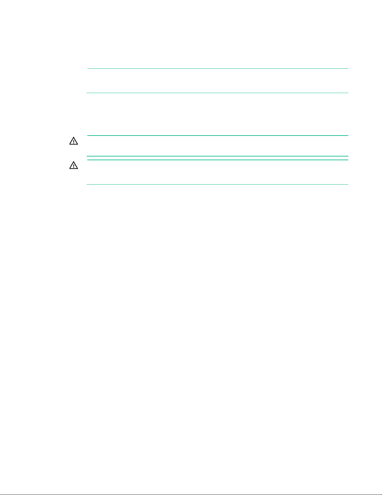
Access the product rear panel
To access the product rear panel, release the cable management arm and swing the arm away from the
rack as indicated.
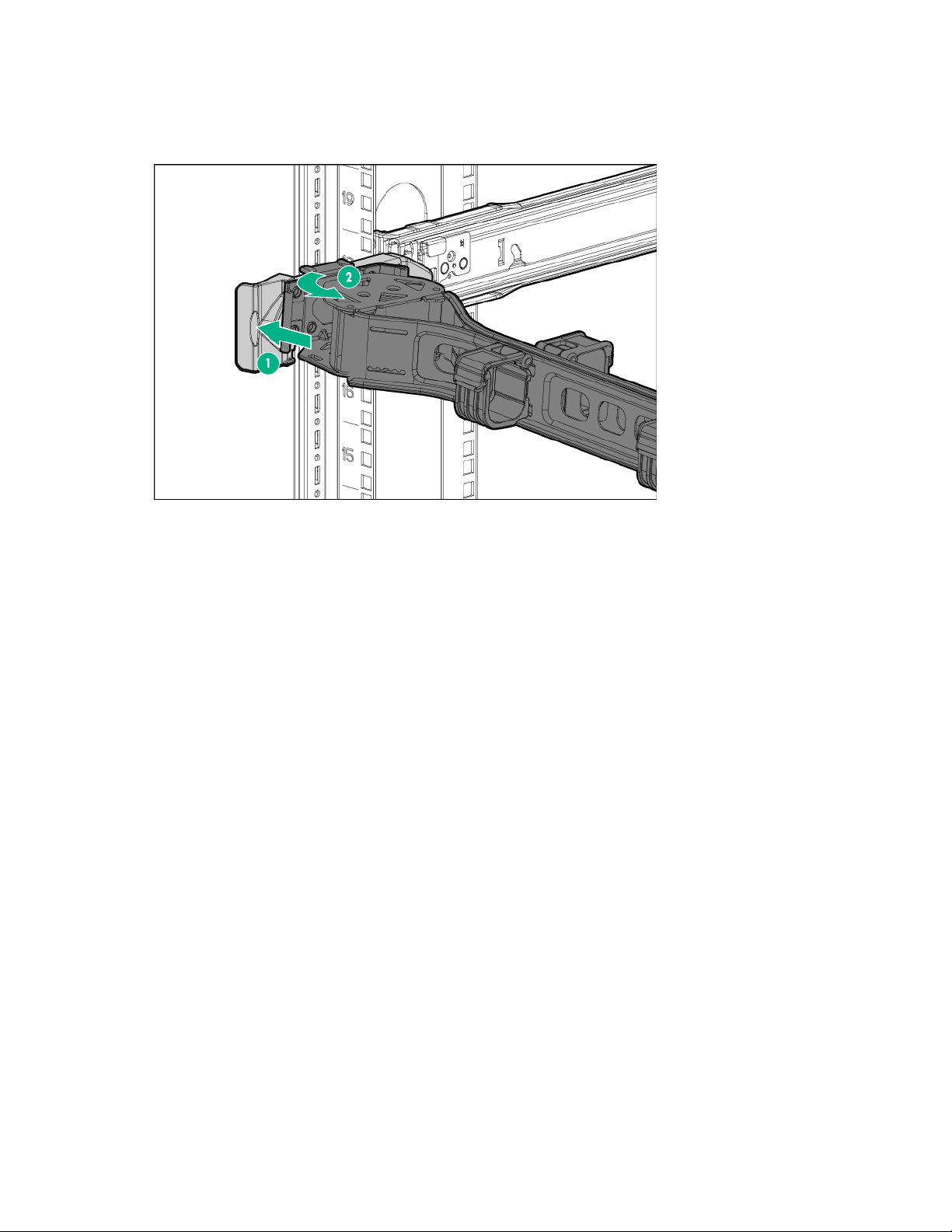
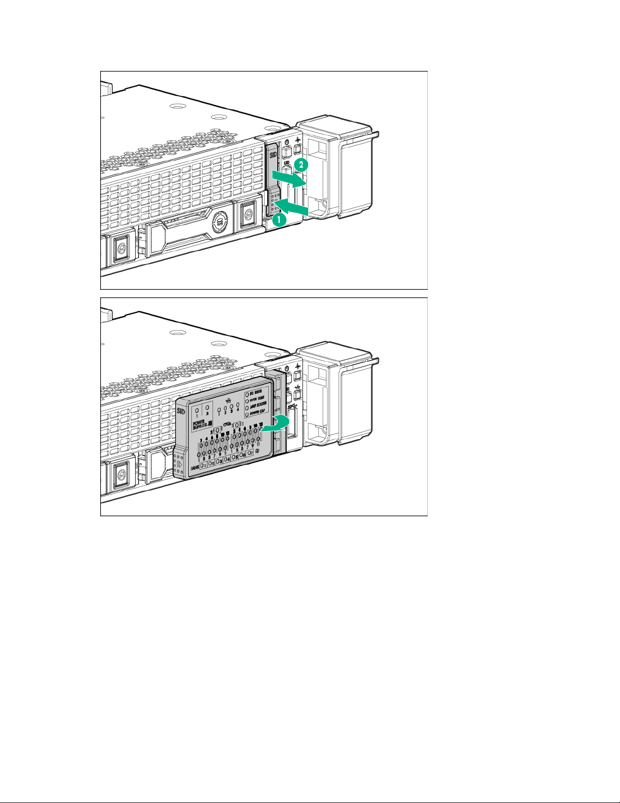
Access the Systems Insight Display
To access the optional pop-out HPE Systems Insight Display:
1. Press and release the panel.
2. After the display fully ejects, rotate the display to view the LEDs.
Removal and replacement procedures 18
• 8SFF
Removal and replacement procedures 19
• 4LFF
Safety considerations
Preventing electrostatic discharge
Before performing service procedures, review all the safety information.
To prevent damaging the system, be aware of the precautions you need to follow when setting up the
system or handling parts. A discharge of static electricity from a finger or other conductor may damage
system boards or other static-sensitive devices. This type of damage may reduce the life expectancy of
the device.
To prevent electrostatic damage:
• Avoid hand contact by transporting and storing products in static-safe containers.
• Keep electrostatic-sensitive parts in their containers until they arrive at static-free workstations.
Removal and replacement procedures 20

• Place parts on a grounded surface before removing them from their containers.
ce the risk of injury from electric shock hazards, do not open this
To reduce the risk of injury from electric shock hazards, do not open this
k of electric shock, fire, or damage to the equipment, do
This symbol indicates the presence of a hot surface or hot component. If this surface
This symbol indicates that the component exceeds the recommended weight for one
observe local occupational health and safety requirements and guidelines for manual
To reduce the risk of injury from electric shock, remove all power cords
• Avoid touching pins, leads, or circuitry.
• Always be properly grounded when touching a static-sensitive component or assembly.
Symbols on equipment
The following symbols may be placed on equipment to indicate the presence of potentially hazardous
conditions.
This symbol indicates the presence of hazardous energy circuits or electric shock
hazards. Refer all servicing to qualified personnel.
WARNING: To redu
enclosure. Refer all maintenance, upgrades, and servicing to qualified personnel.
This symbol indicates the presence of electric shock hazards. The area contains no
user or field serviceable parts. Do not open for any reason.
WARNING:
enclosure.
This symbol on an RJ-45 receptacle indicates a network interface connection.
WARNING: To reduce the ris
not plug telephone or telecommunications connectors into this receptacle.
is contacted, the potential for injury exists.
WARNING: To reduce the risk of injury from a hot component, allow the surface to
cool before touching.
12.25 kg - 15.31
kg
27.00 lb - 33.76 lb
individual to handle safely.
WARNING: To reduce the risk of personal injury or damage to the equipment,
material handling.
These symbols, on power supplies or systems, indicate that the equipment is
supplied by multiple sources of power.
WARNING:
to completely disconnect power from the system.
Server warnings and cautions
Before installing a server, be sure that you understand the following warnings and cautions.
WARNING: To reduce the risk of electric shock, personal injury, and damage to the
equipment:
• Do not attempt to service any parts of the equipment other than those specified in the
following procedure. Any other activities may require that you shut down the server and
remove the power cord.
• Installation and maintenance of this product must be performed by individuals who are
knowledgeable about the procedures, precautions and hazards associated with the
product.
WARNING: To reduce the risk of personal injury from hot surfaces, allow the drives and the
internal system components to cool before touching them.
Removal and replacement procedures 21
CAUTION: Do not operate the server for long periods with the access panel open or
removed. Operating the server in this manner results in improper airflow and improper cooling
that can lead to thermal damage.
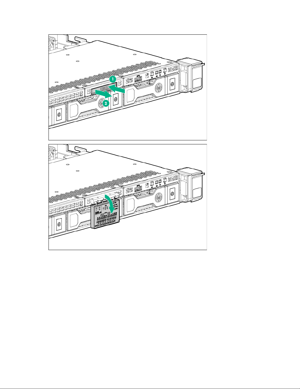
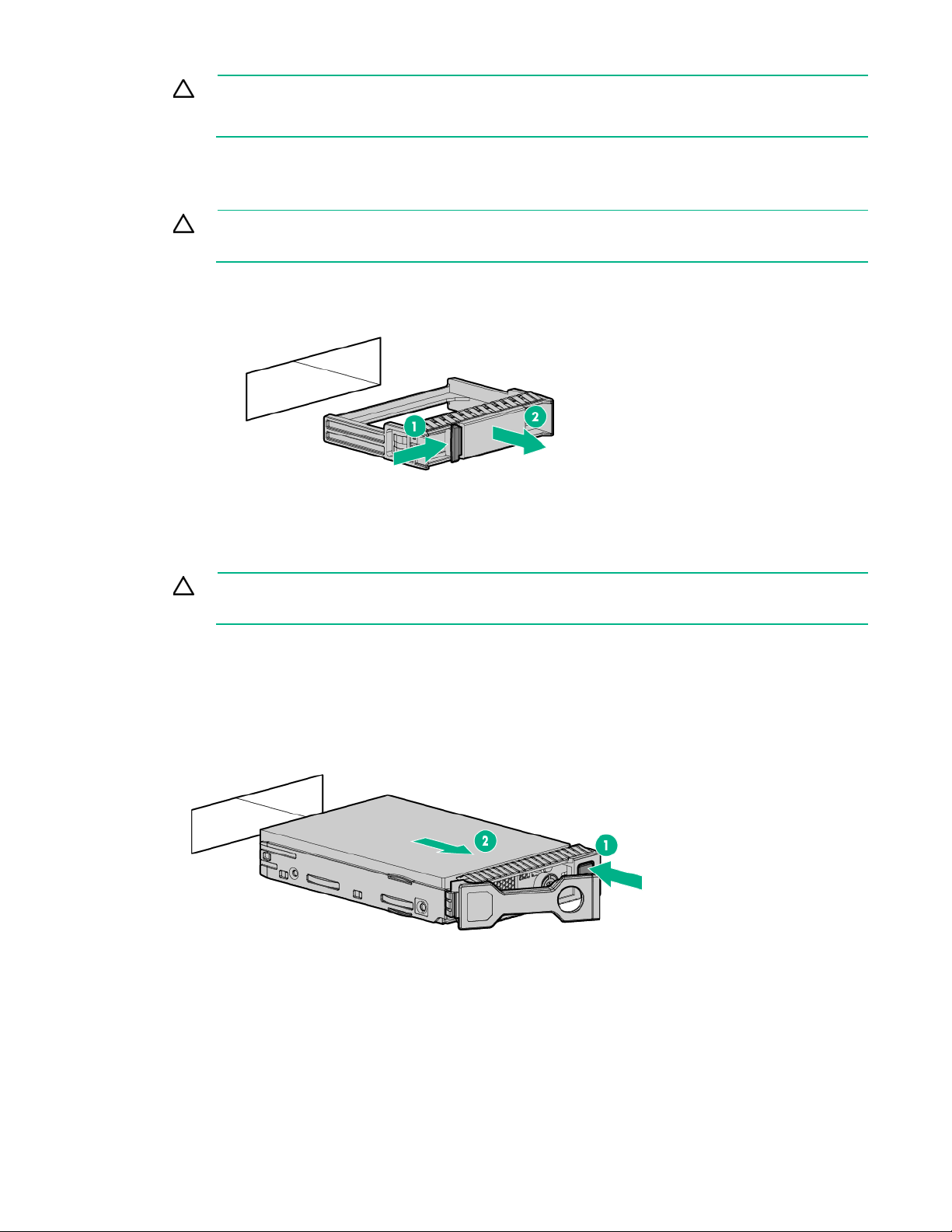
Drive blank
CAUTION: To prevent improper cooling and thermal damage, do not operate the server
unless all bays are populated with either a component or a blank.
To remove the component:
1. Remove the drive blank.
To replace the blank, slide the blank into the bay until it locks into place.
Hot-plug SAS/SATA drives and SSDs
CAUTION: To prevent improper cooling and thermal damage, do not operate the server
unless all bays are populated with either a component or a blank.
To remove the component:
1. Back up all server data on the drive.
2. Determine the status of the drive from the drive LED definitions ("Hot-plug drive LED definitions" on
page 83).
3. Remove the drive.
To replace the component, reverse the removal procedure.
NVMe drives
NVMe drives are supported on this server when the HPE 10SFF (6 NVMe + 4 SAS/SATA) Express Bay
Enablement Option or the 2SFF HPE Express Bay Drive Cage is installed. For more information on which
bays support NVMe drives, see "Device numbers (on page 82)."
Removal and replacement procedures 22
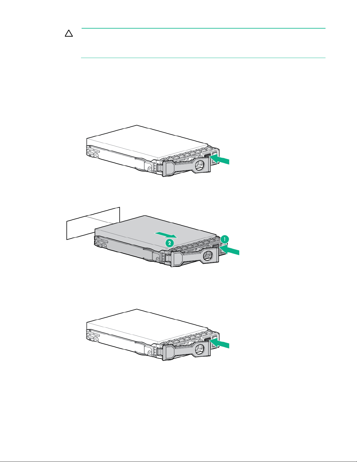
CAUTION: Do not remove an NVMe SSD from the drive bay while the Do Not Remove
button LED is flashing. The Do Not Remove button LED flashes to indicate the device is still in
use. Removal of the NVMe SSD before the device has completed and ceased signal/traffic
flow can cause loss of data.
To remove the component:
1. Press the Power button.
The Do Not Remove button LED illuminates and flashes. Do not press the button while the LED is
illuminated.
2. When the Do Not Remove button LED is no longer flashing or illuminated, press the Do Not Remove
button to open the release lever.
3. Remove the drive.
To replace the component:
1. Press the Do Not Remove button to open the release handle.
Removal and replacement procedures 23
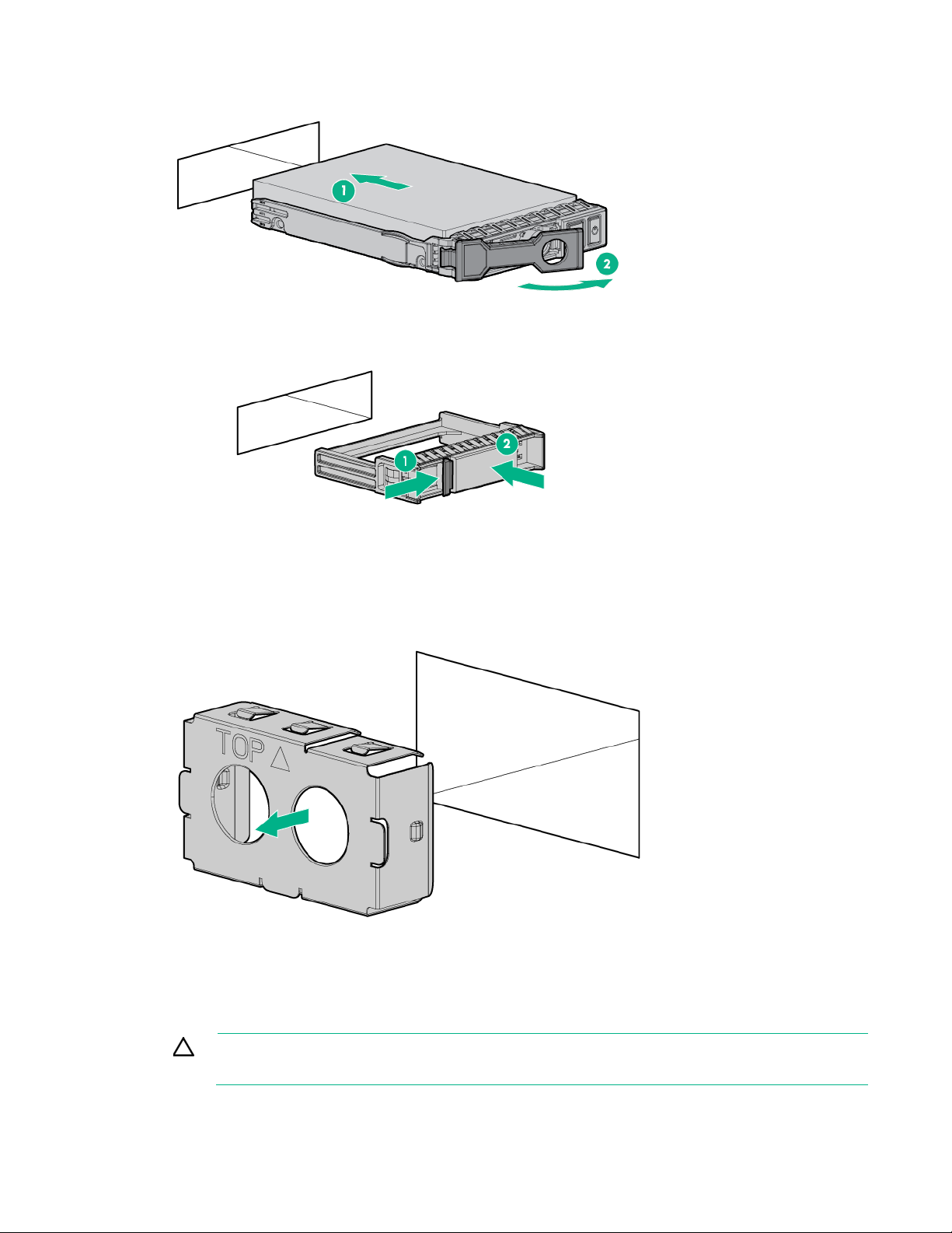
2.
Install the drives.
3. Install an SFF drive blank in any unused drive bays.
Power supply blank
Remove the component as indicated.
To replace the component, reverse the removal procedure.
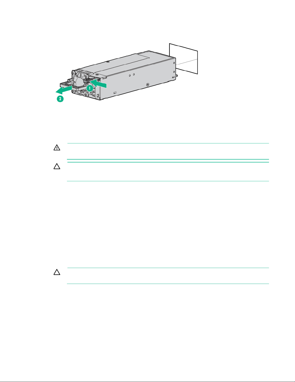
AC power supply
CAUTION: To prevent improper cooling and thermal damage, do not operate the server
unless all bays are populated with either a component or a blank.
Removal and replacement procedures 24
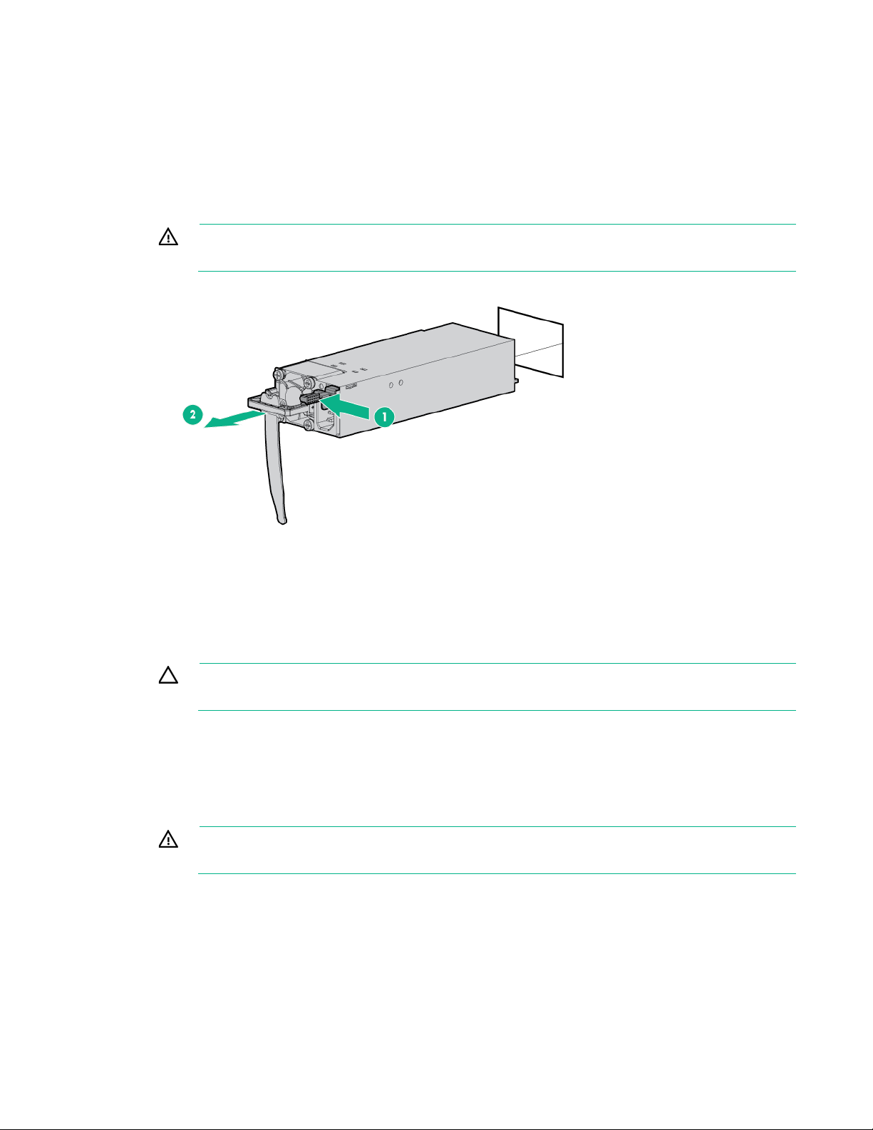
To remove the component:
To reduce the risk of personal injury from hot surfaces, allow the power supply or
1. Power down the server (on page 16).
2. Remove all power:
a. Disconnect each power cord from the power source.
b. Disconnect each power cord from the server.
3. Access the product rear panel (on page 18).
4. Remove the power supply.
WARNING:
power supply blank to cool before touching it.
To replace the component, reverse the removal procedure.
HPE 750W Flex Slot Hot Plug Battery Backup Module
CAUTION: To prevent improper cooling and thermal damage, do not operate the server
unless all bays are populated with either a component or a blank.
To remove the component:
1. Access the product rear panel (on page 18).
2. If the FSBBU is cabled to a second FSBBU, disconnect the FSBBU jumper cable from the second
FSBBU.
3. Remove the FSBBU.
WARNING: To reduce the risk of personal injury from hot surfaces, allow the power supply or
power supply blank to cool before touching it.
Removal and replacement procedures 25
server in this manner results in improper airflow and improper cooling
To replace the component, reverse the removal procedure.
Access panel
WARNING: To reduce the risk of personal injury from hot surfaces, allow the drives and the
internal system components to cool before touching them.
CAUTION: Do not operate the server for long periods with the access panel open or
removed. Operating the
that can lead to thermal damage.
To remove the component:
1. Power down the server (on page 16).
2. Extend the server from the rack (on page 17).
Open or unlock the locking latch, slide the access panel to the rear of the chassis, and remove the
access panel.
To replace the component:
1. Place the access panel on top of the server with the hood latch open. Allow the panel to extend past
the rear of the server approximately 1.25 cm (0.5 inch).
2. Push down on the hood latch. The access panel slides to a closed position.
Primary PCI riser cage
CAUTION: To prevent damage to the server or expansion boards, power down the server
and remove all AC power cords before removing or installing the PCI riser cage.
1. Power down the server (on page 16).
2. Remove all power:
a. Disconnect each power cord from the power source.
b. Disconnect each power cord from the server.
3. Do one of the following:
o Extend the server from the rack (on page 17).
o Remove the server from the rack (on page 17).
4. Remove the access panel ("Access panel" on page 26).
Removal and replacement procedures 26
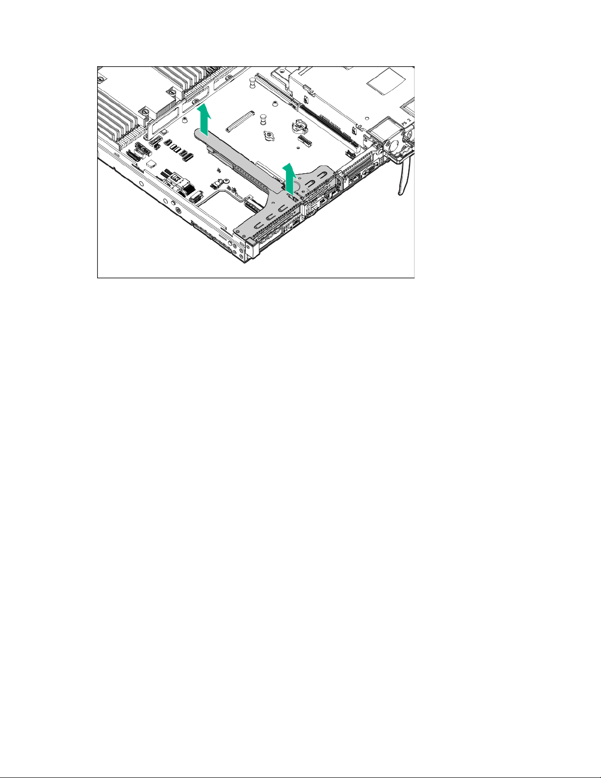
5.
Remove the primary PCI riser cage.
To replace the component, reverse the removal procedure.
PCIe riser board
To remove the component:
1. Power down the server (on page 16).
2. Remove all power:
a. Disconnect each power cord from the power source.
b. Disconnect each power cord from the server.
3. Do one of the following:
o Extend the server from the rack (on page 17).
o Remove the server from the rack (on page 17).
4. Remove the access panel ("Access panel" on page 26).
5. Remove the PCIe riser cage:
o Primary PCIe riser cage ("Primary PCI riser cage" on page 26, "2SFF Express Bay drive
backplane" on page 44)
o Secondary PCIe riser cage ("Secondary PCI riser cage" on page 28)
6. Remove any expansion boards from the PCIe riser cage ("Expansion boards" on page 51).
Removal and replacement procedures 27
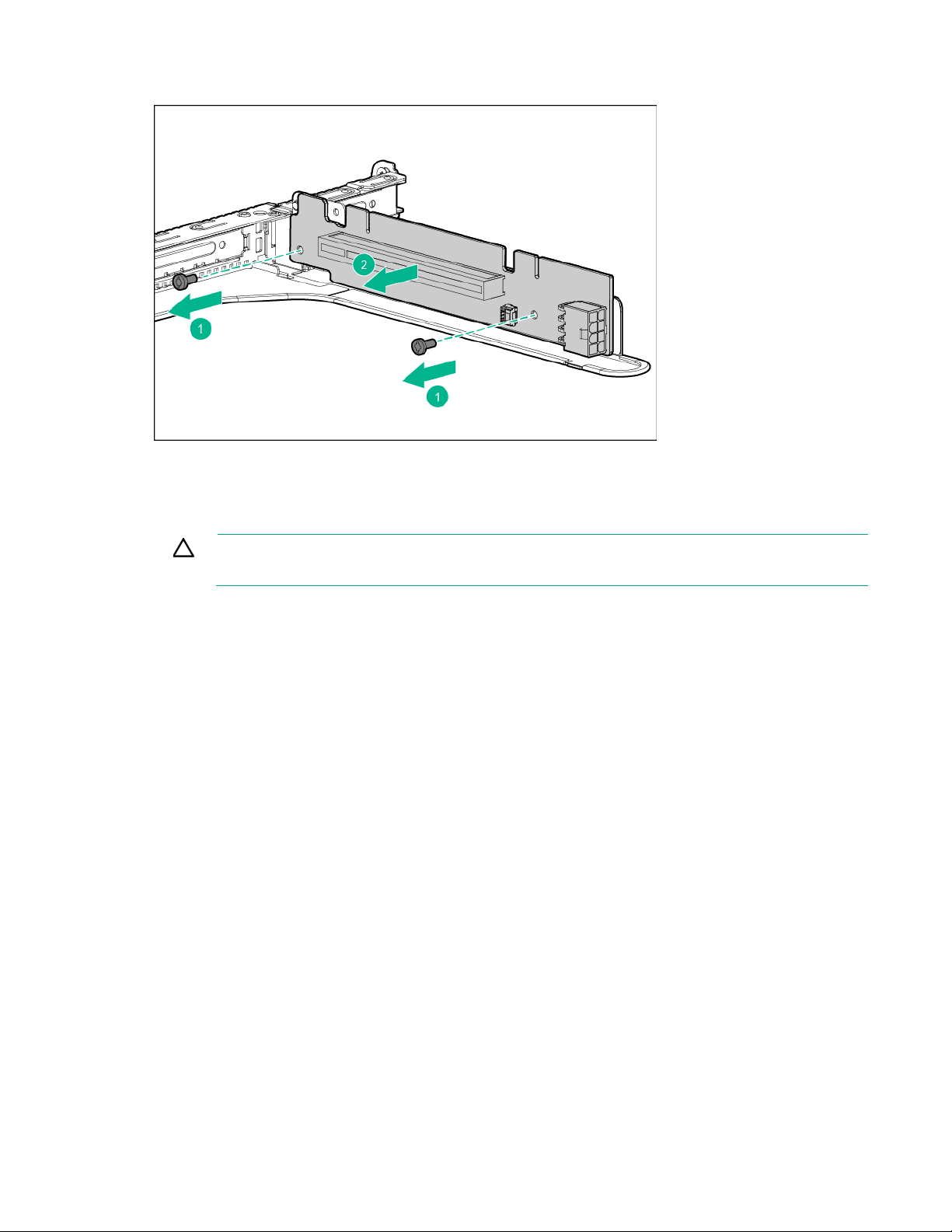
7.
Remove the PCIe riser board.
To replace the component, reverse the removal procedure.
Secondary PCI riser cage
CAUTION: To prevent damage to the server or expansion boards, power down the server
and remove all AC power cords before removing or installing the PCI riser cage.
1. Power down the server (on page 16).
2. Remove all power:
a. Disconnect each power cord from the power source.
b. Disconnect each power cord from the server.
3. Do one of the following:
o Extend the server from the rack (on page 17).
o Remove the server from the rack (on page 17).
4. Remove the access panel ("Access panel" on page 26).
Removal and replacement procedures 28
5.
Remove the secondary PCI riser cage.
To replace the component, reverse the removal procedure.
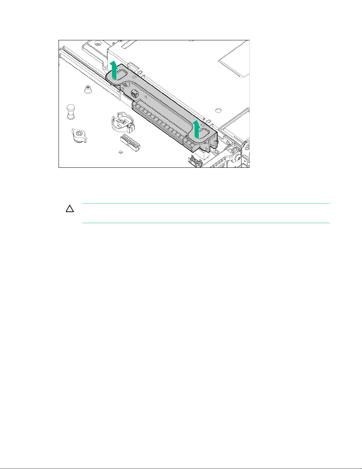
Primary PCIe riser blank
CAUTION: To prevent improper cooling and thermal damage, do not operate the server
unless all PCI slots have either an expansion slot cover or an expansion board installed.
To remove the component:
1. Power down the server (on page 16).
2. Remove all power:
a. Disconnect each power cord from the power source.
b. Disconnect each power cord from the server.
3. Do one of the following:
o Extend the server from the rack (on page 17).
o Remove the server from the rack (on page 17).
4. Remove the access panel ("Access panel" on page 26).
5. Remove the PCI riser cage ("Primary PCI riser cage" on page 26, "2SFF Express Bay drive
backplane" on page 44).
Removal and replacement procedures 29
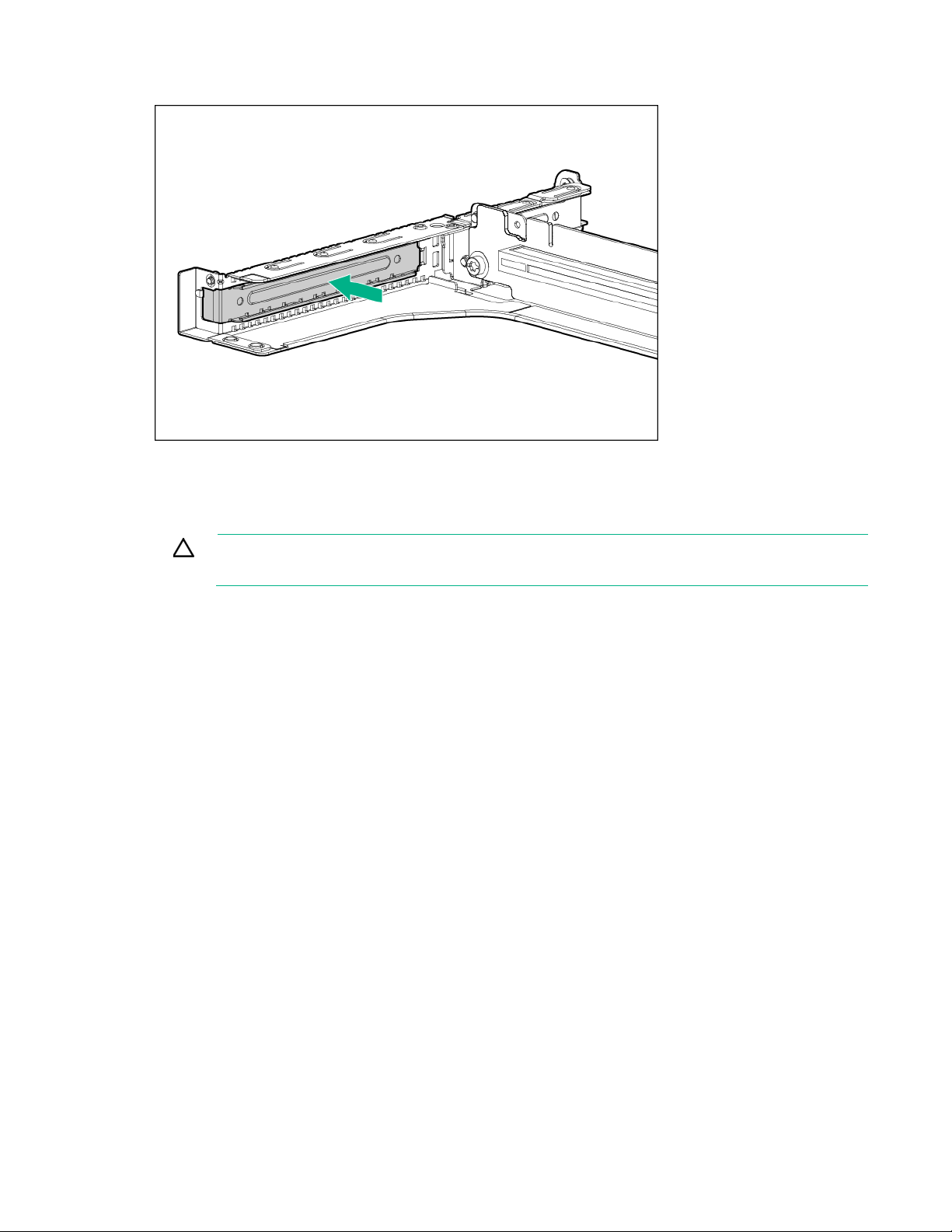
6.
Remove the primary PCIe riser blank.
To replace the component, reverse the removal procedure.
Secondary PCIe riser blank
CAUTION: To prevent improper cooling and thermal damage, do not operate the server
unless all PCI slots have either an expansion slot cover or an expansion board installed.
To remove the component:
1. Power down the server (on page 16).
2. Remove all power:
a. Disconnect each power cord from the power source.
b. Disconnect each power cord from the server.
3. Do one of the following:
o Extend the server from the rack (on page 17).
o Remove the server from the rack (on page 17).
4. Remove the access panel ("Access panel" on page 26).
Removal and replacement procedures 30
 Loading...