


HP ProLiant DL320 Generation 3 Server
Maintenance and Service Guide
March 2005 (Second Edition)
Part Number 373044-002

© Copyright 2005 Hewlett-Packard Development Company, L.P.
Microsoft and Windows NT are U.S. registered trademarks of Microsoft Corporation.
Intel, Celeron, and Pentium® are U.S. registered trademarks of Intel Corporation or its subsidiaries in the United
States and other countries.
Linux is a U.S. registered trademark of Linus Torvalds.
The information contained herein is subject to change without notice. The only warranties for HP products and
services are set forth in the express warranty statements accompanying such products and services. Nothing herein
should be construed as constituting an additional warranty. HP shall not be liable for technical or editorial errors
or omissions contained herein.
March 2005 (Second Edition)
Part Number 373044-002

Contents
About This Guide
Audience Assumptions............................................................................................................................... vii
Technician Notes........................................................................................................................................ vii
Where to Go for Additional Help.............................................................................................................. viii
Integrated Management Log ............................................................................................................... viii
Telephone Numbers............................................................................................................................ viii
Chapter 1
Illustrated Parts Catalog
Customer Self Repair ................................................................................................................................ 1-1
Mechanical Parts Exploded View ............................................................................................................. 1-2
System Components Exploded View ........................................................................................................ 1-3
Mechanical Parts and System Components Spares List............................................................................ 1-4
Chapter 2
Removal and Replacement Procedures
Required Tools and Software .................................................................................................................... 2-1
Safety Considerations................................................................................................................................ 2-1
Electrostatic Discharge Information.......................................................................................................... 2-1
Symbols on Equipment ............................................................................................................................. 2-2
Rack Warnings .......................................................................................................................................... 2-2
Server Warnings and Precautions.............................................................................................................. 2-3
Removal and Replacement Procedures ..................................................................................................... 2-3
Powering Down the Server........................................................................................................................ 2-4
Access Panel.............................................................................................................................................. 2-5
Drive Assembly......................................................................................................................................... 2-7
LED/PWR Switch Board .................................................................................................................... 2-7
Diskette Drive ..................................................................................................................................... 2-8
Optical Drive....................................................................................................................................... 2-9
Hard Drive Overview .............................................................................................................................. 2-11
Guidelines for Installing SATA Hard Drives ................................................................................... 2-11
Guidelines for Installing SCSI Hard Drives ..................................................................................... 2-11
Hard Drive Identification Numbers .................................................................................................. 2-11
SATA Hard Drives.................................................................................................................................. 2-12
SCSI Hard Drives.................................................................................................................................... 2-13
PCI Riser Board Assembly...................................................................................................................... 2-15
Expansion Board............................................................................................................................... 2-16
Single Channel Wide Ultra320 SCSI Adapter.................................................................................. 2-17
Integrated SATA RAID Controller Module ..................................................................................... 2-17
HP ProLiant DL320 Generation 3 Server Maintenance and Service Guide iii

Contents
Fan Assembly...........................................................................................................................................2-17
Fans..........................................................................................................................................................2-19
Cables.......................................................................................................................................................2-21
SATA Drive Cables...........................................................................................................................2-21
Power Supply...........................................................................................................................................2-23
Battery...................................................................................................................................................... 2-24
Memory Modules.....................................................................................................................................2-26
Processor.................................................................................................................................................. 2-29
System Board........................................................................................................................................... 2-31
Chapter 3
Diagnostic Tools
SmartStart Software ................................................................................................................................... 3-1
SmartStart Scripting Toolkit ...................................................................................................................... 3-1
HP Instant Support Enterprise Edition....................................................................................................... 3-2
ROM-Based Setup Utility..........................................................................................................................3-2
ROMPaq Utility ......................................................................................................................................... 3-3
System Online ROM Flash Component Utility .........................................................................................3-3
Integrated Management Log ...................................................................................................................... 3-3
Integrated Lights-Out Technology............................................................................................................. 3-4
Automatic Server Recovery.......................................................................................................................3-4
HP Systems Insight Manager.....................................................................................................................3-4
HP Insight Diagnostics ..............................................................................................................................3-5
USB Support .............................................................................................................................................. 3-5
Internal USB Functionality ........................................................................................................................ 3-5
Chapter 4
Component Identifications
Rear Panel Components.............................................................................................................................4-2
Expansion Slot Component ................................................................................................................. 4-3
System Board Components .................................................................................................................4-4
System Switches ........................................................................................................................................4-5
System Maintenance Switch (SW1)....................................................................................................4-5
Non-Maskable Interrupt Switch (NMI button/SW3)...........................................................................4-6
Front Panel Buttons and LEDs ..................................................................................................................4-6
Rear Panel LEDs........................................................................................................................................4-7
System Board LEDs................................................................................................................................... 4-8
Chapter 5
Specifications
System Unit................................................................................................................................................5-2
Power Supply.............................................................................................................................................5-2
Memory...................................................................................................................................................... 5-3
Optical CD-ROM Drive............................................................................................................................. 5-4
Integrated Intel ICH6A SATA Controller .................................................................................................5-5
Optional Hard Drives.................................................................................................................................5-5
SATA Hard Drives..............................................................................................................................5-5
Integrated Broadcom 10/100/1000 Gigabit Server Auto-Switching Network Interface Controller (NIC) 5-6
iv HP ProLiant DL320 Generation 3 Server Maintenance and Service Guide

Contents
Index
List of Figures
1-1 Mechanical parts exploded view......................................................................................................... 1-2
1-2 System components exploded view .................................................................................................... 1-3
2-1 Removing the access panel ................................................................................................................. 2-6
2-2 Loosen the thumbscrew and slide the assembly toward the back of the server .................................. 2-7
2-3 Removing the LED/PWR switch board.............................................................................................. 2-8
2-4 Remove the diskette drive................................................................................................................... 2-9
2-5 Remove the Optical drive ................................................................................................................. 2-10
2-6 SATA device numbers...................................................................................................................... 2-12
2-7 Removing the SATA hard drive tray from the chassis ..................................................................... 2-12
2-8 Removing the SATA hard drive from a hard drive tray ................................................................... 2-13
2-9 Removing the SCSI hard drive tray from the chassis ....................................................................... 2-14
2-10 Removing the SCSI hard drive from a hard drive tray ..................................................................... 2-14
2-11 Removing the PCI riser board........................................................................................................... 2-15
2-12 Removing an expansion board from the PCI riser board assembly .................................................. 2-16
2-13 Disconnecting the fan assembly power cables (processor heatsink removed for clarity)................. 2-18
2-14 Lifting the fan assembly out of the chassis ....................................................................................... 2-18
2-15 Locating the system fans................................................................................................................... 2-19
2-16 Removing one fan from the fan assembly ........................................................................................ 2-20
2-17 Disconnecting the SATA cables ....................................................................................................... 2-21
2-18 Disconnecting the drive assembly cables.......................................................................................... 2-22
2-19 Removing the power supply ............................................................................................................. 2-23
2-20 Locating and removing the system battery ....................................................................................... 2-25
2-21 Identifying DIMM sockets on the system board............................................................................... 2-26
2-22 Removing a DIMM from a DIMM socket........................................................................................ 2-27
2-23 Installing a DIMM in a DIMM socket.............................................................................................. 2-28
2-24 Locating the processor on the system board ..................................................................................... 2-29
2-25 Loosening screws on the heatsink and removing the heatsink ......................................................... 2-30
2-26 Removing the processor from the system board............................................................................... 2-31
2-27 Removing the system board.............................................................................................................. 2-32
4-1 Rear panel components ....................................................................................................................... 4-2
4-2 Expansion slot component .................................................................................................................. 4-3
4-3 System board components .................................................................................................................. 4-4
4-4 System switches.................................................................................................................................. 4-5
4-5 Front panel LEDs................................................................................................................................ 4-7
4-6 Rear panel LEDs................................................................................................................................. 4-8
4-7 System board status LEDs .................................................................................................................. 4-9
List of Tables
1-1 Mechanical and System Spare Parts List ............................................................................................ 1-4
2-1 System Fans ...................................................................................................................................... 2-19
2-2 DIMM Socket Identification............................................................................................................. 2-26
4-1 Rear Panel Components...................................................................................................................... 4-2
4-2 Expansion Slot Component................................................................................................................. 4-3
4-3 System Board Components................................................................................................................. 4-4
4-4 System Switches ................................................................................................................................. 4-5
HP ProLiant DL320 Generation 3 Server Maintenance and Service Guide v

Contents
4-5 System Maintenance Switch (SW1) Settings ......................................................................................4-6
4-6 Front Panel LEDs ................................................................................................................................4-7
4-7 Rear Panel LEDs .................................................................................................................................4-8
4-8 System board status LEDs................................................................................................................... 4-9
5-1 System Unit Specifications..................................................................................................................5-2
5-2 Power Supply Specifications...............................................................................................................5-2
5-3 Power Supply Specifications
continued ..................................................................................................5-3
5-4 SDRAM DIMM Specifications...........................................................................................................5-3
5-5 Optical CD-ROM Drive Specifications...............................................................................................5-4
5-6 Intel ICH6A SATA Controller Specifications.....................................................................................5-5
5-7 SATA Hard Drive Specifications........................................................................................................5-5
5-8 Integrated NC7782 10/100/1000 Gigabit Server Auto-Switching NIC Specifications (WOL and PXE
capable) ...............................................................................................................................................5-6
vi HP ProLiant DL320 Generation 3 Server Maintenance and Service Guide
This maintenance and service guide can be used for reference when servicing an HP ProLiant
DL320 Generation 3 server.
WARNING: To reduce the risk of personal injury from electric shock and hazardous
energy levels, only authorized service technicians should attempt to repair this
equipment. Improper repairs can create conditions that are hazardous.
Audience Assumptions
This guide is for service technicians. HP assumes you are qualified in the servicing of
computer equipment and trained in recognizing hazard in products with hazardous energy
levels and are familiar with weight and stability precautions for rack installations.
Technician Notes
WARNING: Only authorized technicians trained by HP should attempt to repair this
equipment. All troubleshooting and repair procedures are detailed to allow only
subassembly/module-level repair. Because of the complexity of the individual boards
and subassemblies, no one should attempt to make repairs at the component level or
to make modifications to any printed wiring board. Improper repairs can create a safety
hazard.
WARNING: To reduce the risk of personal injury from electric shock and hazardous
energy levels, do not exceed the level of repairs specified in these procedures.
Because of the complexity of the individual boards and subassemblies, do not attempt
to make repairs at the component level or to make modifications to any printed wiring
board. Improper repairs can create conditions that are hazardous.
WARNING: To reduce the risk of electric shock or damage to the equipment:
• Disconnect power from the system by unplugging all power cords from the power
supplies.
• Do not disable the power cord grounding plug. The grounding plug is an important
safety feature.
About This Guide
• Plug the power cord into a grounded (earthed) electrical outlet that is easily
accessible at all times.
HP ProLiant DL320 Generation 3 Server Maintenance and Service Guide vii

About This Guide
CAUTION: To properly ventilate the system, you must provide at least 7.6 cm (3.0 in) of
clearance at the front and back of the server.
CAUTION: The computer is designed to be electrically grounded (earthed). To ensure proper
operation, plug the AC power cord into a properly grounded AC outlet only.
NOTE: Any indications of component replacement or printed wiring board modifications may void any
warranty.
Where to Go for Additional Help
In addition to this guide, the following information sources are available:
• HP ProLiant DL320 Generation 3 Server User Guide
• Server Quick Reference Guide
• Server training guides
• Server advisories and bulletins
• QuickFind information services
• HP Systems Insight Manager software (HP SIM)
• HP ProLiant Servers Troubleshooting Guide
• HP ROM-Based Setup and Utility User Guide
• HP Integrated Lights-Out User Guide
• QuickSpecs
Integrated Management Log
The server includes an integrated, nonvolatile management log that contains fault and
management information. The contents of the Integrated Management Log (IML) can be
viewed with HP SIM.
Telephone Numbers
For the name of the nearest HP authorized reseller:
• In the United States, call 1-800-345-1518.
• In Canada, call 1-800-263-5868.
• In other locations, refer to the HP website.
For HP technical support:
viii HP ProLiant DL320 Generation 3 Server Maintenance and Service Guide

About This Guide
• In North America:
− Call 1-800-HP-INVENT (1-800-474-6836). This service is available 24 hours a day,
7 days a week. For continuous quality improvement, calls may be recorded or
monitored.
− If you have purchased a Care Pack (service upgrade), call 1-800-633-3600. For more
information about Care Packs, refer to the HP website.
y Outside North America, call the nearest HP Technical Support Phone Center. For
telephone numbers for worldwide Technical Support Centers, refer to the HP website
www.hp.com
HP ProLiant DL320 Generation 3 Server Maintenance and Service Guide ix

This chapter provides the illustrated parts breakdown and spare parts list for the
HP ProLiant DL320 Generation 3 Server. Table 1-1 in this chapter provides names and
ordering numbers for all referenced spare parts.
Customer Self Repair
HP's customer self-repair program offers you the fastest service under either warranty or
contract. It enables HP to ship replacement parts directly to you so that you can replace them.
Using this program, you can replace parts at your own convenience.
A convenient, easy-to-use program:
z An HP support specialist will diagnose and assess whether a replacement part is required
to address a system problem. The specialist will also determine whether you can replace
the part.
1
Illustrated Parts Catalog
z Replacement parts are express-shipped. Most in-stock parts are shipped the very same
day you contact HP. You may be required to send the defective part back to HP, unless
otherwise instructed.
z Available for most HP products currently under warranty or contract. For information on
the warranty service, refer to the HP website
(http://h18004.www1.hp.com/products/servers/platforms/warranty/index.html
For more information about HP's customer self-repair program, contact your local service
provider. For the North American program, refer to the HP website
(http://www.hp.com/go/selfrepair
Customer replaceable parts are identified in the following tables.
).
).
HP ProLiant DL320 Generation 3 Server Maintenance and Service Guide 1-1
Illustrated Parts Catalog
Mechanical Parts Exploded View
Figure 1-1: Mechanical parts exploded view
1-2 HP ProLiant DL320 Generation 3 Server Maintenance and Service Guide

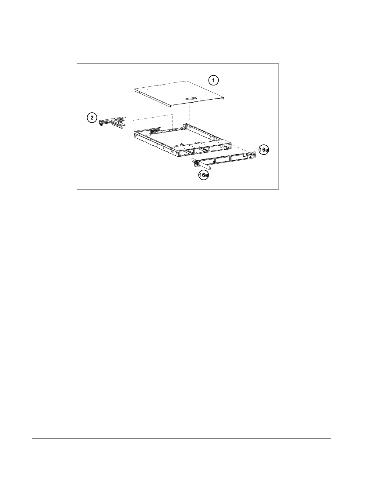
System Components Exploded View
Figure 1-2: System components exploded view
Illustrated Parts Catalog
HP ProLiant DL320 Generation 3 Server Maintenance and Service Guide 1-3

Illustrated Parts Catalog
Mechanical Parts and System Components Spares List
Table 1-1: Mechanical and System Spare Parts List
Item Description Spare Part Number Customer
Mechanical Components
1 Access panel 378631-001 Yes
2 PCI-X riser board assembly 361387-001 Yes
3 Fan assembly 378701-001 Yes
Power
4 500-Watt power supply 378630-001 Yes
Boards
5 LED/PWR switch board 378627-001 Yes
6 PCI Express board* 378626-001 Yes
7 System board 378623-001 Yes
8 SATA Backplane 378625-001 Yes
Processor
9 a) 2.93-GHz Intel® Celeron® processor 378619-001 Yes
b) 3.4-GHz Intel Pentium® 4 processor 1MB* 378620-001 Yes
c) 3.4-GHz Intel Pentium 4 processor 2 MB * 384787-001 Yes
d) 3.6-GHz Intel Pentium 4 processor 1 MB* 378621-001 Yes
10 Heatsink 378622-001 Yes
Memory
11 a) PC3200 DDR ECC Registered DIMM 512 MB 351657-001 Yes
b) PC3200 DDR ECC Registered DIMM 1 GB* 351658-001 Yes
Mass Storage Devices
12 Optical devices/diskette assembly
a) CD-ROM 390629-001 Yes
b) DVD-ROM * 383981-001 Yes
c) SCSI hard drive
1. SCSI 18-GB U320 HD
2. SCSI 36-GB U320 HD
3. SCSI 72-GB U320 HD
d) SATA hard drive
1. SATA 80-GB HD
2. SATA 160-GB HD
3. SATA 250-GB HD
e) Diskette drive assembly* 390530-001 Yes
1. 289240-001
2. 289241-001
3. 289243-001
1. 353042-001
2. 353043-001
3. 353044-001
Self Repair
Yes
Yes
Yes
Yes
Yes
Yes
* Not shown
continued
1-4 HP ProLiant DL320 Generation 3 Server Maintenance and Service Guide
Illustrated Parts Catalog
Table 1-1: Mechanical and System Spare Parts List continued
Item Description Spare Part
Number
Miscellaneous
13 Replacement battery, 3-V lithium* 234556-001 Yes
14 SATA cable kit* 378629-001 Yes
15 Cable kit* 378628-001 Yes
a) hard drive cable* Yes
b) Optical device/diskette assembly drive cable* Yes
c) USB* Yes
16 Miscellaneous plastics kit 378632-001 Yes
a) Bezel Yes
b) PCI card guide Yes
c) Bezel screws* Yes
d) Air baffle Yes
e) Pull tab Yes
17 Return kit* 378633-001 Yes
18 Country kit* 378675-001 Yes
Option Kit Spares
19 Rack mounting hardware kit* 360104-001 Yes
20
* Not shown
Cable management arm Kit*
360105-001 Yes
Customer Self
Repair
HP ProLiant DL320 Generation 3 Server Maintenance and Service Guide 1-5

Removal and Replacement Procedures
This chapter provides subassembly and module-level removal and replacement procedures
for HP ProLiant DL320 Generation 3 Servers. After completing all necessary removal and
replacement procedures, run the diagnostics program to verify that all components operate
properly.
Required Tools and Software
You may need the following items for some procedures:
z Phillips screwdriver
z T-15/T-10 Torx screwdriver
z SmartStart CD
- ROM-Based Setup Utility (RBSU)
- Array Diagnostics Utility (ADU)
2
- Diagnostics software
z Wrist strap
Safety Considerations
z Before performing any service procedure, review all safety information.
Electrostatic Discharge Information
An electrostatic discharge (ESD) can damage static-sensitive devices or microcircuitry.
Proper packaging and grounding techniques are required to prevent damage. To prevent
damage due to ESD, observe the following precautions:
z Transport products in static-safe containers such as conductive tubes, bags, or boxes.
z Keep electrostatic-sensitive parts in their containers until they arrive at static-free
stations.
z Cover workstations with approved static-dissipating material. Use a wrist strap
connected to the work surface as well as properly grounded tools and equipment.
z Keep the work area free of nonconductive materials such as ordinary plastic assembly
aids and foam packing.
HP ProLiant DL320 Generation 3 Server Maintenance and Service Guide 2-1
Removal and Replacement Procedures
z Ensure proper grounding before touching a static-sensitive component or assembly.
z Avoid touching pins, leads, or circuitry.
z Always place drives with the Printed Circuit Board (PCB) assembly-side down.
z Use conductive field service tools.
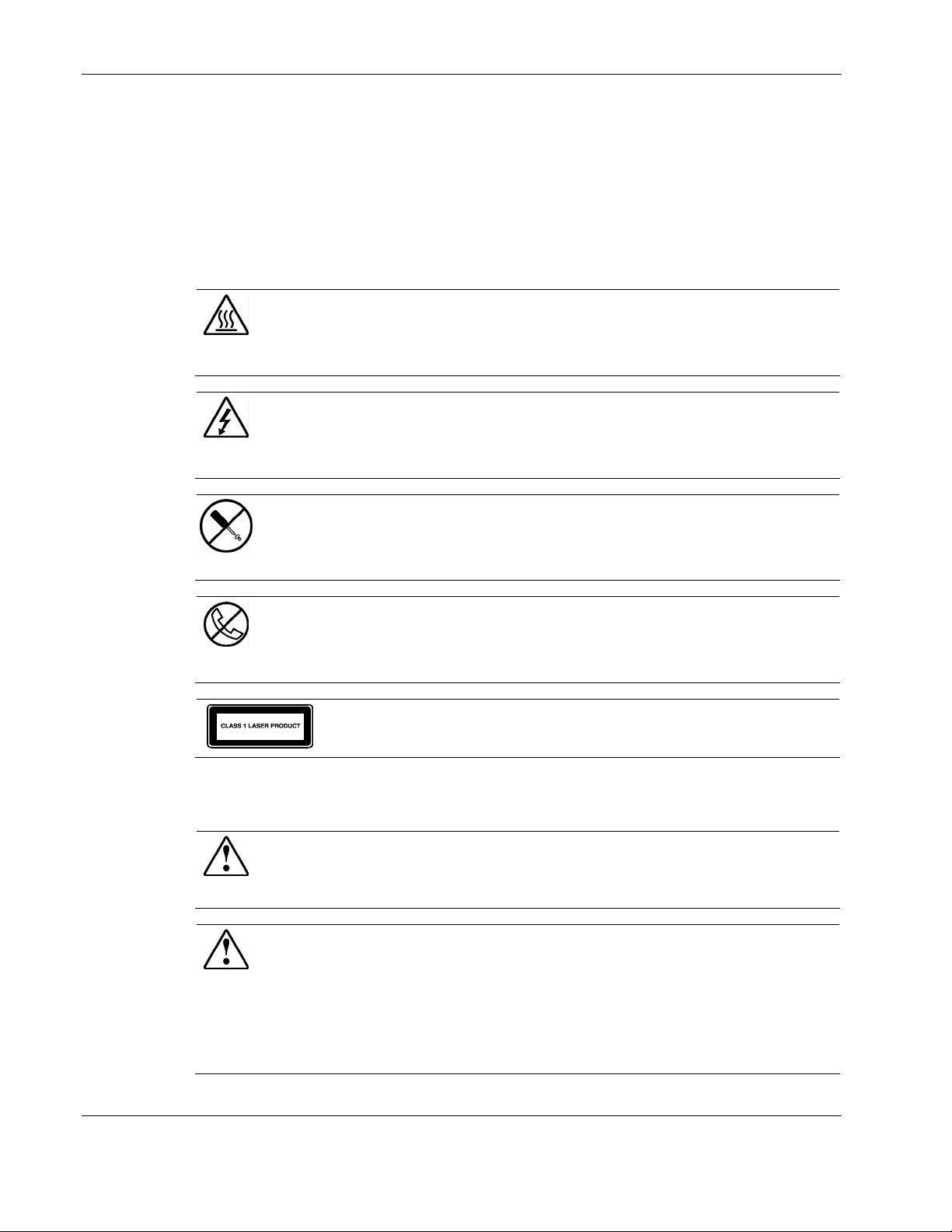
Symbols on Equipment
Any surface or area of the equipment marked with these symbols indicates the
presence of a hot surface or hot component.
WARNING: To reduce the risk of injury from a hot component, allow the surface to cool
before touching it.
To reduce the risk of injury from electric shock hazards, do not open this enclosure.
WARNING: Any surface or area of the equipment marked with these symbols indicates
the presence of electric shock hazards. The enclosed area contains no
operator-serviceable parts.
This symbol indicates the presence of electric shock hazards. The enclosed area
contains no user or field-serviceable parts. Do not open for any reason.
WARNING: To reduce the risk of injury from electric shock hazards, do not open this
enclosure.
Any RJ-45 receptacle marked with these symbols indicates a network interface
connection.
WARNING: To reduce the risk of electric shock, fire, or damage to the equipment, do
not plug telephone or telecommunications connectors into this receptacle.
This label or equivalent is located on the surface of the CD-ROM or DVD-ROM
drive. This label indicates that the product is classified as a Class 1 Laser Product.
Rack Warnings
WARNING: To reduce the risk of personal injury or damage to equipment, always be
sure that the rack is adequately stabilized before extending a component from the rack.
A rack may become unstable if more than one component is extended for any reason.
Extend only one component at a time.
WARNING: To reduce the risk of personal injury or damage to the equipment, be sure
that:
z The leveling jacks are extended to the floor.
z The full weight of the rack rests on the leveling jacks.
z The stabilizers are attached to the rack, if it is a single rack installation.
z The racks are coupled together in multiple rack installations.
2-2 HP ProLiant DL320 Generation 3 Server Maintenance and Service Guide
WARNING: When installing the server in a telco rack, make certain that the rack frame
is adequately secured to the building structure at the top and bottom.
WARNING: To reduce the risk of personal injury or damage to the equipment, at least
two people are needed to safely unload the rack from the pallet. An empty 42U rack
weighs 115 kg (253 lb), is over 2.1 m (7 ft) tall, and may become unstable when being
moved on its casters. Do not stand in front of the rack as it rolls down the ramp from
the pallet. Handle the rack from both sides.
Server Warnings and Precautions
WARNING: To reduce the risk of personal injury from hot surfaces, allow the hot-plug
drives and the internal system components to cool before touching them.
WARNING: To reduce the risk of electric shock or damage to the equipment:
Do not disable the power cord grounding plug. The grounding plug is an important
safety feature.
Plug the power cord into a grounded (earthed) electrical outlet that is easily accessible
at all times.
Unplug the power cord from the power supply to disconnect power to the equipment.
CAUTION: Protect the server from power fluctuations and temporary interruptions with a
regulating uninterruptible power supply (UPS). This device protects the hardware from
damage caused by power surges and voltage spikes and keeps the system in operation
during a power failure.
CAUTION: The server
cooling is not achieved if the system access panel is removed.
must always be operated with the system access panel closed. Proper
Removal and Replacement Procedures
Removal and Replacement Procedures
Use the procedures in this section to perform service events on the ProLiant DL320 G3
Server.
HP ProLiant DL320 Generation 3 Server Maintenance and Service Guide 2-3
Removal and Replacement Procedures
Powering Down the Server
The server does not completely power down when the front panel power button is pressed.
The button toggles server power between On and Standby. In Standby, the server removes
power from most electronics and drives, portions of the power supply and some internal
circuitry remain active. To completely remove all power from the system, disconnect the
power cord from the server.
WARNING: To reduce the risk of injury from electric shock, remove the power cord to
completely disconnect power from the system.
WARNING: To reduce the risk of personal injury or damage to the equipment, be sure
that only one component is extended at a time. A rack may become unstable if more
than one component is extended at the same time.
WARNING: Because the rack allows you to stack computer components in a vertical
rather than a horizontal plane, you must take precautions to provide for rack stability
and safety to protect both personnel and property. Heed all cautions and warnings
throughout the installation instructions that come with the server.
WARNING: To reduce the risk of personal injury or damage to the equipment, place the
server on a sturdy table or workbench whenever it is removed from the rack for device
accessibility. Refer to the HP ProLiant DL320 Generation 3 Server User Guide for
further information on working with racks.
CAUTION: Moving the Power On/Off switch to the Off position does not completely remove
system power. Some portions of the power supply and some internal circuitry remain active.
Disconnect all power cords from the server to remove all power from the system.
CAUTION: ESD can damage electronic components. Be sure you are properly grounded
before beginning any installation procedure. For more information, see “Electrostatic
Discharge Information” in this chapter.
NOTE: Microsoft® Windows NT® users may use the Power Down Manager to power down the server.
For information on this system utility, refer to the NTREADME.HLP file on the NT Software Support
Diskettes.
2-4 HP ProLiant DL320 Generation 3 Server Maintenance and Service Guide
To power down the server:
1. Press the power button to toggle the server to standby. The power LED on the power
button changes from green to amber.
2. Listen for the fan noise to stop to indicate that the server is powered down.
3. Disconnect the power cord first from the AC outlet and then from the server. The power
LEDs turn off.
4. Disconnect all remaining cables on the server rear panel, including cables extending from
external connectors on expansion boards.
5. Remove the server from the rack and position it securely on a workbench or other solid
surface for stability and safety.
Access Panel
To access the system board, processor, memory modules, expansion slot, and other internal
components, remove the access panel. Observe the following warnings and cautions.
Removal and Replacement Procedures
WARNING: The front panel Power On/Off switch does not completely shut off all
system power. Portions of the power supply and some internal circuitry remain active
until AC power is removed.
WARNING: To reduce the risk of personal injury from hot surfaces, allow the internal
system components to cool before touching them.
CAUTION: Do not operate the server without the access panel installed. The access panel is
required for proper airflow. Operating the server without the access panel prevents proper
airflow and results in improper cooling and possible thermal damage.
CAUTION: Before removing the server access panel, be sure that the server is powered
down and that the power cord is disconnected from the server and the electrical outlet.
CAUTION: To avoid the risk of damage to the system or expansion boards, remove all power
cords before installing or removing expansion boards. When the Power On/Off switch is in the
Off position, auxiliary power is still connected to the PCI expansion slot and may damage the
card.
CAUTION: ESD can damage electronic components. Ensure proper grounding before
beginning any installation procedure.
HP ProLiant DL320 Generation 3 Server Maintenance and Service Guide 2-5
Removal and Replacement Procedures
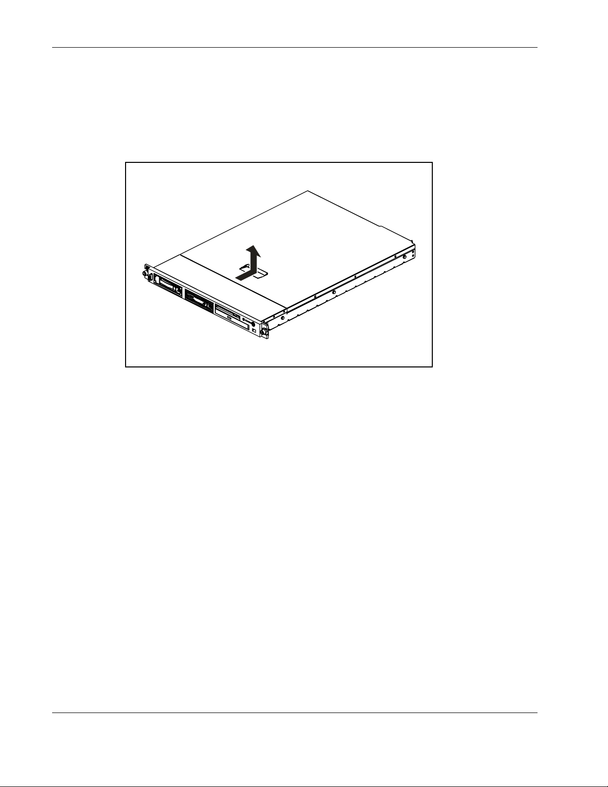
To remove the access panel:
1. Power down the server. See “Powering Down the Server” in this chapter.
2. Loosen rear thumbscrew by using the T-15/T-10 Torx screwdriver or the flat screwdriver.
3. Slide the access panel approximately 1.25 cm (0.5 in) toward the rear of the unit and lift
the panel to remove it.
Figure 2-1: Removing the access panel
To replace the access panel, reverse steps 1 through 3.
2-6 HP ProLiant DL320 Generation 3 Server Maintenance and Service Guide
Drive Assembly
The server contains a removable media drive assembly including one LED/PWR switch
board, one optical drive, and one diskette drive.
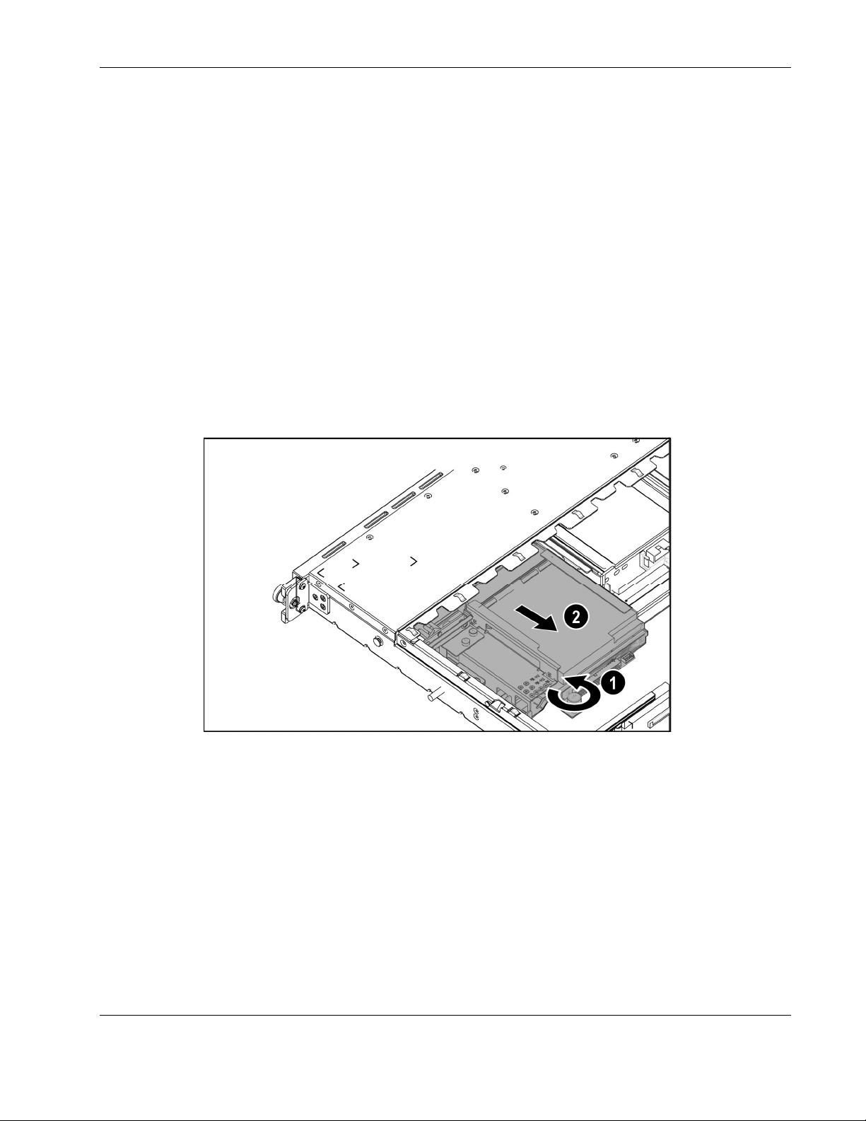
To remove the drive assembly:
1. Power down the server. See “Powering Down the Server” in this chapter.
2. Remove the access panel. See “Access Panel” in this chapter.
3. Disconnect the LED/PWR switch board cable from the system board.
4. Disconnect the diskette drive cable from the diskette drive.
5. Disconnect the two optical drive cables from the optical drive.
6. Remove the fan module.
7. Loosen the one thumbscrew of the drive assembly (1).
8. Slide the drive assembly gently toward the back of the server (2).
Removal and Replacement Procedures
Figure 2-2: Loosen the thumbscrew and slide the assembly toward
the back of the server
IMPORTANT : Carefully remove the LED/PWR switch board to avoid damaging the LEDs.
Reverse steps 1 through 8 to replace the drive assembly.
LED/PWR Switch Board
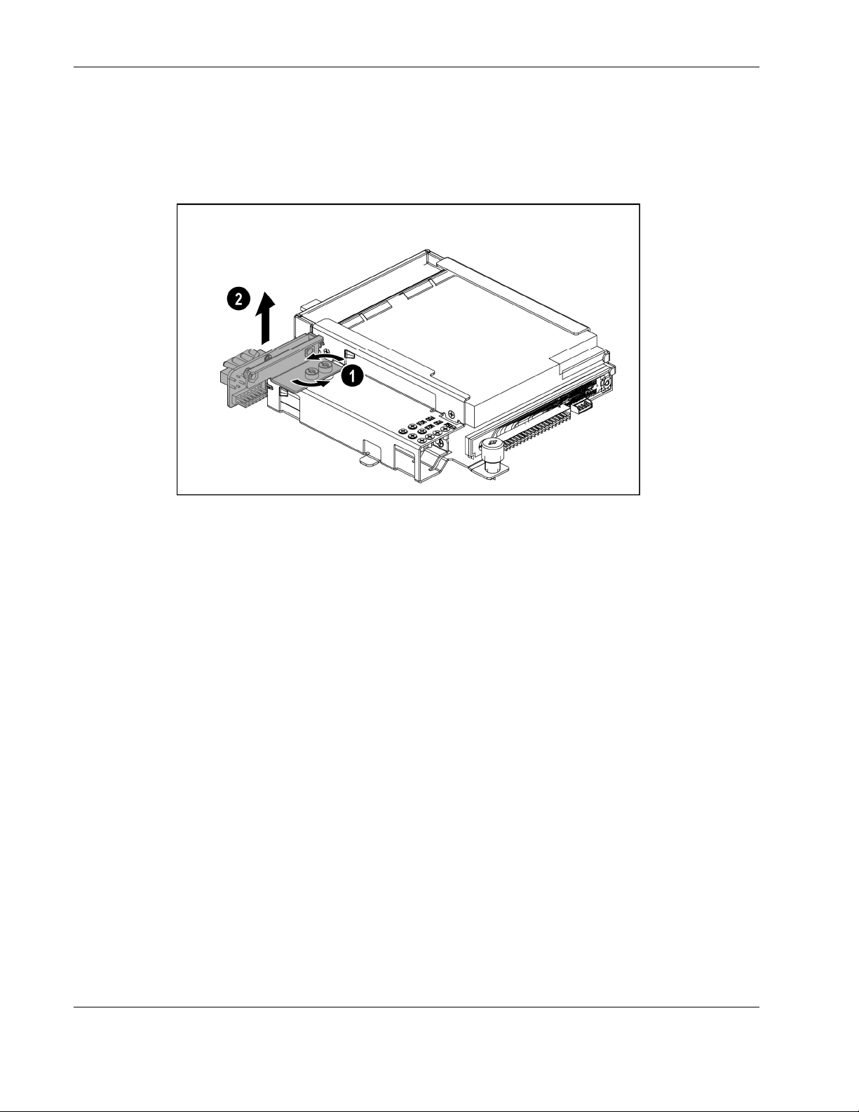
To remove the LED/PWR switch board:
1. Power down the server. See “Powering Down the Server” in this chapter.
HP ProLiant DL320 Generation 3 Server Maintenance and Service Guide 2-7
Removal and Replacement Procedures
2. Remove the access panel. See “Access Panel” in this chapter.
3. Disconnect the drive assembly cables. See “Drive Assembly” in this chapter.
4. Unscrew both LED/PWR switch board screws from the drive assembly (1) and remove
the LED/PWR switch board (2).
Figure 2-3: Removing the LED/PWR switch board
IMPORTANT: Carefully remove the LED/PWR switch board to avoid damaging the LEDs.
Reverse steps 1 through 4 to replace the LED/PWR switch board.
Diskette Drive
To remove the diskette drive:
1. Power down the server. See “Powering Down the Server” in this chapter.
2. Remove the access panel. See “Access Panel” in this chapter.
3. Disconnect the drive assembly cables. See “Drive Assembly” in this chapter.
4. Remove the LED/PWR switch board. See “LED/PWR Switch Board” in this chapter.
5. Remove the 4 screws holding diskette drive (1) and slide the drive out of the assembly
(2).
2-8 HP ProLiant DL320 Generation 3 Server Maintenance and Service Guide

Removal and Replacement Procedures
Figure 2-4: Remove the diskette drive
To replace the diskette drive, reverse steps 1 through 5.
NOTE: See the HP ProLiant DL320 Generation 3 Server User Guide for instructions on installing the
diskette drive.
NOTE: If the diskette drive must be replaced due to failure, the diskette drive cable must be removed
from the failed drive and installed on the replacement. See Chapter 1, “Illustrated Parts Catalog,” for
illustrations.
Optical Drive
To remove the optical drive:
1. Power down the server. See “Powering Down the Server” in this chapter.
2. Remove the access panel. See “Access Panel” in this chapter
3. Disconnect the drive assembly cables. See “Drive Assembly” in this chapter.
4. Remove 4 screws holding optical drive (1) and slide the drive out of the assembly (2).
HP ProLiant DL320 Generation 3 Server Maintenance and Service Guide 2-9

Removal and Replacement Procedures
Figure 2-5: Remove the Optical drive
To replace the optical drive, reverse steps 1 through 4.
NOTE: See the HP ProLiant DL320 Generation 3 Server User Guide for instructions on installing the
optical drive.
NOTE: If the drive must be replaced due to failure, the optical drive backplane must be removed from
the failed drive and installed on the replacement. See Chapter 1, “Illustrated Parts Catalog,” for
illustrations.
2-10 HP ProLiant DL320 Generation 3 Server Maintenance and Service Guide

Hard Drive Overview
The server contains two drive bays for SATA hard drives or non-hot pluggable SCSI hard
drives. Two individual SATA channels exist, one for each of the hard drives. The server ships
standard with two 1-inch drive trays for use with two 1-inch pluggable SATA hard drives.
The following sections provide general guidelines and installation procedures for installing or
upgrading hard drives.
Guidelines for Installing SATA Hard Drives
When installing SATA hard drives in the server, observe the following general guidelines:
z Populate hard drive bays starting with the lowest SATA device number. Device 0 serves
as the primary boot drive.
z Set the jumpers on both SATA drives to Cable-Select mode.
z Do not add more than two SATA drives in the DL320 G3 server.
IMPORTANT: SATA hard drives must be configured to the Cable-Select mode.
NOTE: SATA drives are set to Cable-Select mode by default.
NOTE: Refer to the documentation shipped with the hard drive to determine how to set the jumpers on
the SATA hard drives to Cable-Select mode, if they are not already set in Cable-Select mode.
Removal and Replacement Procedures
Guidelines for Installing SCSI Hard Drives
Each SCSI hard drive installed in the server must be configured with a unique SCSI ID
number. Unique identification allows the system to search for the lowest numbered drive to
use as a bootable partition. By default, the jumpers on SCSI hard drives are set to ID 0 and
may need to be reset when the drive is installed as an optional or replacement drive in the
server.
CAUTION: Before removing the server access panel, be sure that the server is powered
down and that the power cord is disconnected from the server and the electrical outlet.
NOTE: SCSI drives are set to Cable-Select mode by default.
Hard Drive Identification Numbers
The servers include two 1-inch hard drive trays. Hard drives installed in the server are labeled
as Device 1 and Device 2 in Figure 2-6 for clarification.
IMPORTANT: Always populate hard drive bays starting with the lowest hard drive number.
HP ProLiant DL320 Generation 3 Server Maintenance and Service Guide 2-11

Removal and Replacement Procedures
Figure 2-6: SATA device numbers
SATA Hard Drives
To remove a hard drive from the hard drive bay:
1. Power down the server. See “Powering Down the Server” in this chapter.
2. Flip open the tray lever to release the hard drive tray (1), and then slide the tray out of the
chassis (2).
Figure 2-7: Removing the SATA hard drive tray from the chassis
2-12 HP ProLiant DL320 Generation 3 Server Maintenance and Service Guide

Removal and Replacement Procedures
3. Remove the four screws that secure the hard drive to the hard drive tray (1).
4. Remove the hard drive from the hard drive tray (2).
Figure 2-8: Removing the SATA hard drive from a hard drive tray
To replace the SATA hard drive, reverse steps 1 through 4.
IMPORTANT: While replacing the drive, make sure that the LED light pipes of the tray are seated
properly in their slots.
SCSI Hard Drives
To remove a hard drive from the hard drive bay:
1. Power down the server. See “Powering Down the Server” in this chapter.
2. Remove the access panel. See “Access Panel” in this chapter.
3. Disconnect the SCSI cables from the hard drives.
4. Disconnect the power cables from the hard drives.
5. Loosen the thumbscrew that secures the hard drive tray to the chassis (1).
6. Slide the tray toward the front of the server and lift the tray out of the chassis (2).
HP ProLiant DL320 Generation 3 Server Maintenance and Service Guide 2-13

Removal and Replacement Procedures
Figure 2-9: Removing the SCSI hard drive tray from the chassis
7. Remove the four screws at the bottom side that secure the hard drive to the hard drive
tray (1).
8. Remove the hard drive from the hard drive tray (2).
Figure 2-10: Removing the SCSI hard drive from a hard drive tray
CAUTION: Review “Guidelines for SCSI Hard Drives” in this chapter to ensure proper jumper
settings and hard drive configuration.
CAUTION: When connecting the power cable to the hard drives, ensure that the connectors
are installed so that the red wire faces right when viewed from the front of the server.
2-14 HP ProLiant DL320 Generation 3 Server Maintenance and Service Guide

IMPORTANT: Ensure that the hard drives are installed with the data and power connectors along the
bottom of the tray, facing away from the front vent holes..
To replace the SCSI hard drive, reverse steps 1 through 8.
PCI Riser Board Assembly
To remove the PCI riser board assembly:
1. Power down the server. See “Powering Down the Server” in this chapter.
2. Remove the access panel. See “Access Panel” in this chapter.
3. Disconnect any cables connecting an existing expansion board to the system board.
4. Unscrew the 2 thumbscrews on rear of chassis (1).
5. Lift and remove the PCI riser board from the server chassis (2).
Removal and Replacement Procedures
Figure 2-11: Removing the PCI riser board
CAUTION: When removing the PCI riser board assembly, be careful to avoid damaging to
the system cables.
CAUTION: Be careful to remove the large PCI expansion board, if it is present in the
assembly, since it is guided and supported with a bracket at its end.
When replacing an expansion board, refer to “Expansion Board” following this procedure.
HP ProLiant DL320 Generation 3 Server Maintenance and Service Guide 2-15

Removal and Replacement Procedures
IMPORTANT: Do not replace the PCI riser board assembly in the chassis unless all installation and
cabling procedures are complete.
Reverse steps 1 through 5 to replace the PCI riser board assembly, ensuring that the assembly
seats properly in the retainers on the rear of the chassis and the guide located on the system
board.
Expansion Board
To remove an expansion board:
CAUTION: To avoid the risk of damage to the system or expansion boards, remove all power
cords before installing or removing an expansion board. When the front panel power switch is
off, auxiliary power is still connected to the PCI expansion slot and may damage the card.
1. Power down the server. See “Powering Down the Server” in this chapter.
2. Remove the access panel. See “Access Panel” in this chapter.
3. Disconnect all cables from the expansion board.
4. Remove the PCI riser board assembly. See “PCI Riser Board Assembly” in this chapter.
5. Apply even pressure to pull the expansion board out of its socket in the PCI riser board
assembly.
Figure 2-12: Removing an expansion board from the PCI riser
board assembly
Reverse steps 1 through 5 to replace an expansion board. Use the PCI card guide on the
assembly to position the board in the socket.
IMPORTANT: Be sure that the expansion board is seated securely in the expansion slot before
replacing the PCI riser board assembly and access panel.
2-16 HP ProLiant DL320 Generation 3 Server Maintenance and Service Guide

Single Channel Wide Ultra320 SCSI Adapter
To remove a single channel wide ultra320 SCSI adapter:
1. Locate the PCI-X slot 1 riser connector. See Figure 4-2 in the Chapter 4 Connectors,
Switches, and LED Indicators.
2. Remove the PCI riser board assembly. See “PCI riser board assembly” in this chapter.
3. Remove a single channel-wide ultra320 SCSI adapter. See “Expansion Board” in this
chapter.
Reverse steps 2 through 3 to replace a single channel-wide ultra320 SCSI adapter. Use the
PCI card guide on the assembly to position the adapter in the socket.
Integrated SATA RAID Controller Module
To remove an integrated SATA RAID controller module:
1. Locate the PCI-X slot 1 riser connector. See Figure 4-2 in the Chapter 4 Connectors,
Switches, and LED Indicators.
Removal and Replacement Procedures
2. Remove the PCI riser board assembly. See “PCI riser board assembly” in this chapter.
3. Remove an integrated SATA RAID controller module. See “Expansion Board” in this
chapter.
Reverse steps 2 through 3 to replace an integrated SATA RAID controller module. Use the
PCI card guide on the assembly to position the module in the socket.
Fan Assembly
To remove the fan assembly:
1. Power down the server. See “Powering Down the Server” in this chapter.
2. Remove the access panel. See “Access Panel” in this chapter.
3. Lift the air baffle from the server chassis.
4. Disconnect the fan assembly power cables (1 to 4) from the fan connectors on the system
board.
WARNING: To reduce the risk of personal injury from hot surfaces, allow the internal system
components to cool before touching them.
HP ProLiant DL320 Generation 3 Server Maintenance and Service Guide 2-17

Removal and Replacement Procedures
Figure 2-13: Disconnecting the fan assembly power cables
(processor heatsink removed for clarity)
5. Push in and hold the fan assembly tab to unlock the fan assembly from the chassis (1)
6. Lift the fan assembly out of the chassis (2)
Figure 2-14: Lifting the fan assembly out of the chassis
Reverse steps 1 through 6 to replace the fan assembly.
IMPORTANT: See the server hood label or “System Board Connector,” in Chapter 4, “Connectors,
Switches, and LED Indicators,” for correct fan cable connections.
2-18 HP ProLiant DL320 Generation 3 Server Maintenance and Service Guide

Fans
Removal and Replacement Procedures
The server contains four system fans. The fans are located on the fan assembly. Use Figure 215 and Table 2-1 to locate the system fans.
Figure 2-15: Locating the system fans
NOTE: Fans are spared and replaced individually. Each fan listed in Table 2-1 is a separate spare.
Table 2-1: System Fans
Item Component
1 Fan 1
2 Fan 2
3 Fan 3
4 Fan 4
HP ProLiant DL320 Generation 3 Server Maintenance and Service Guide 2-19

Removal and Replacement Procedures
To remove one fan from the fan assembly:
1. Loosen the screws (1)
2. Slide the fan out of the assembly (2).
Figure 2-16: Removing one fan from the fan assembly
Reverse steps 1 and 2 to replace the fan.
2-20 HP ProLiant DL320 Generation 3 Server Maintenance and Service Guide

Cables
This section contains removal and replacement procedures for SATA drive cables that ship
with the server.
SATA Drive Cables
To remove the SATA drive cables:
1. Power down the server. See “Powering Down the Server” in this chapter.
2. Remove the access panel. See “Access Panel” in this chapter.
3. Remove the fan assembly. See “Fan Assembly” in this chapter.
4. Disconnect the following cables:
a. The system board (1) (4)
b. The hard drive(s) (2) from the backplane
c. The power cables (3) (7)
d. The diskette drive (5)
Removal and Replacement Procedures
e. The optical drive (6)
Figure 2-17: Disconnecting the SATA cables
HP ProLiant DL320 Generation 3 Server Maintenance and Service Guide 2-21

Removal and Replacement Procedures
Figure 2-18: Disconnecting the drive assembly cables
Reverse steps 1 through 6 to replace the cables.
2-22 HP ProLiant DL320 Generation 3 Server Maintenance and Service Guide

Power Supply
To remove the power supply:
1. Power down the server. See “Powering Down the Server” in this chapter.
2. Remove the access panel. See “Access Panel” in this chapter.
3. Disconnect the removable media and hard drive power cables (1)
4. Disconnect the auxiliary power supply cable (2) and the main power supply cable (3)
from the power supply connector on the system board by pressing each locking tab on
the side of the connector and pulling upwards.
5. Remove the four screws that secure the power supply unit to the chassis (4).
6. Lift the power supply from the server (5).
Removal and Replacement Procedures
Figure 2-19: Removing the power supply
Reverse steps 1 through 6 to replace the power supply.
HP ProLiant DL320 Generation 3 Server Maintenance and Service Guide 2-23

Removal and Replacement Procedures
Battery
If the server no longer automatically displays the correct date and time, check the battery that
provides power to the real-time clock. If necessary, replace a used battery with a CR2032
lithium battery. Under normal use, battery life is at least 5 years.
WARNING: This server contains either an internal lithium manganese dioxide, or a
vanadium pent oxide battery. A risk of fire and burns exist if the battery pack is not
handled properly. To reduce the risk of personal injury:
z Do not attempt to recharge.
z Do not expose to temperatures higher than 60°C (140°F).
z Do not disassemble, crush, puncture, short external contacts, or dispose of in fire
or water.
z Replace only with the spare designated for this product.
CAUTION: Loss of BIOS settings occurs when the battery is removed. BIOS settings must be
reconfigured whenever the battery is replaced.
CAUTION: Batteries, battery packs, and accumulators should not be disposed of together
with general household waste. Use the public collection system or return used batteries to the
authorized partners or their agents for proper recycling and disposal.
To remove the battery:
1. Power down the server. See “Powering Down the Server” in this chapter.
2. Remove the access panel. See “Access Panel” in this chapter.
3. Locate the battery on the system board.
4. If necessary, remove the PCI riser board assembly to access the battery location. See
“PCI Riser Board Assembly” in this chapter.
5. Press the battery release lever away from the battery (2).
6. Lift the battery on the lever side and pull it out of the holder (3).
2-24 HP ProLiant DL320 Generation 3 Server Maintenance and Service Guide

Removal and Replacement Procedures
Figure 2-20: Locating and removing the system battery
IMPORTANT: Do not bend the retaining clip during battery replacement. For proper operation, the clip
must maintain a position of contact with the battery.
Reverse steps 1 through 6 to replace the battery, ensuring that the new battery is installed
with the positive side up.
HP ProLiant DL320 Generation 3 Server Maintenance and Service Guide 2-25

Removal and Replacement Procedures
Memory Modules
The server supports up to four PC3200 DDR ECC unbuffered SDRAM DIMMs installed in
four sockets on the system board.
Figure 2-21: Identifying DIMM sockets on the system board
Table 2-2: DIMM Socket Identification
Item Description
1 DIMM socket 1A
2 DIMM socket 2A
3 DIMM socket 3B
4 DIMM socket 4B
Observe the following guidelines when installing additional memory:
z DIMMs must be industry-standard, 512-MB or 1-GB,
3-cm (1.2-in), 184-pin PC3200, 400-MHz DDR ECC memory unbuffered DIMMs. The
DDR memory DIMMs must support CAS Latency 2, where CL=2 or greater. They must
also contain the mandatory Joint Electronic Device Engineering Council (JEDEC)
Serial Presence Detect (SPD) information.
z DIMMs installed in the server must be unbuffered DDR1/400, 2.5 volts and 64-bits
wide.
z Do not mix ECC and non-ECC DIMMs or DIMMs of different speeds. If different types
of DIMMs are mixed, the system will not function properly.
2-26 HP ProLiant DL320 Generation 3 Server Maintenance and Service Guide

Removal and Replacement Procedures
z If only one DIMM is installed, HP recommends installing it in slot 1A.
z All DIMMs installed must be of the same speed (DDR PC3200).
z For best performance the amount of memory in bank A should equal to the amount in
bank B.
IMPORTANT: A DIMM can be installed only one way. Be sure to match the key slots on the module
with the tabs on the memory slot. Push the module down into the slot until it is fully inserted and
properly seated. The system will not recognize improperly aligned or seated DIMMs.
To remove a DIMM from the system board:
1. Power down the server. See “Powering Down the Server” in this chapter.
CAUTION: ESD can damage electronic components. Ensure that you are properly grounded
before beginning any installation procedure. Refer to “Electrostatic Discharge Information” in
this chapter.
2. Remove the access panel. See “Access Panel” in this chapter.
3. Press both DIMM socket latches outward (1). This action releases the DIMM and
partially lifts it out of the socket.
4. Lift out the DIMM (2).
5. Align the key slot in the bottom edge of the DIMM with the tab in the expansion socket.
Figure 2-22: Removing a DIMM from a DIMM socket
HP ProLiant DL320 Generation 3 Server Maintenance and Service Guide 2-27

Removal and Replacement Procedures
To install a DIMM:
1. Gently push the DIMM into the socket on the system board (1). When the DIMM is
properly seated, the latches close (2).
Figure 2-23: Installing a DIMM in a DIMM socket
CAUTION: Use only HP supplied DIMMs. DIMMs from other sources can adversely affect
data integrity.
2. Press down firmly on the DIMM while pushing the latches inward until the latches snap
into place.
2-28 HP ProLiant DL320 Generation 3 Server Maintenance and Service Guide

Processor
To remove the processor:
1. Power down the server. See “Powering Down the Server” in this chapter.
2. Remove the access panel. See “Access Panel” in this chapter.
3. Locate the processor on the system board.
4. Remove the air baffle.
Removal and Replacement Procedures
CAUTION: Always use a new heatsink when replacing processors. Failure to use new
components can cause damage to the processor.
Figure 2-24: Locating the processor on the system board
WARNING: To reduce the risk of personal injury from hot surfaces, allow the internal
system components to cool before touching them.
HP ProLiant DL320 Generation 3 Server Maintenance and Service Guide 2-29

Removal and Replacement Procedures
5. Loosen the four screws securing the heatsink:
a. Loosen each screw three or four turns in the order shown in the illustration.
b. Fully loosen the screws to free the heatsink, being careful not to remove the screw
assemblies from the heat sink.
CAUTION: Heatsink retaining screws should be tightened or loosened in diagonally opposite
pairs (in an "X" pattern). Do not over tighten the screws as this may damage the board,
connectors, or screws. Using the wrench supplied with the system will reduce the possibility of
over tightening the screws.
Figure 2-25: Loosening screws on the heatsink and removing the
heatsink
6. Remove the heatsink from the top of the processor.
7. Lift the processor locking lever (1) and the cover (2)
8. Lift the processor from the socket (3).
2-30 HP ProLiant DL320 Generation 3 Server Maintenance and Service Guide

Removal and Replacement Procedures
Figure 2-26: Removing the processor from the system board
Reverse steps 1 through 8 to reinstall the processor and heatsink. Care should be taken to
install the processor in its right orientation.
CAUTION: Heatsink retaining screws should be tightened or loosened in diagonally opposite
pairs (in an "X" pattern). Do not over tighten the screws as this may damage the board,
connectors, or screws. Using the wrench supplied with the system will reduce the possibility of
over tightening the screws.
CAUTION: Always use a new heatsink when replacing processors. Failure to use new
components may result in damage to the processor.
System Board
To remove the system board:
1. Power down the server. See “Powering Down the Server” in this chapter.
2. Remove the access panel. See “Access Panel” in this chapter.
3. Remove the PCI riser board assembly. See “PCI Riser Board Assembly” in this chapter.
4. Remove any DIMMs. See “Memory Modules” in this chapter.
5. Disconnect the fan cables. See “Fans” in this chapter.
6. Remove the fan assembly. See “Fan Assembly” in this chapter.
7. Disconnect power supply cables from the system board, the hard drive backplane, and
the optical drive backplane. See “Power Supply” in this chapter.
8. Disconnect the SATA drive cables. See “Cables” in this chapter.
9. Disconnect the diskette drive cable. See “Cables” in this chapter.
10. Disconnect the optical drive cable. See “Cables” in this chapter.
HP ProLiant DL320 Generation 3 Server Maintenance and Service Guide 2-31

Removal and Replacement Procedures
11. Disconnect the LED/PWR switch board cable. See “Cables” in this chapter.
12. Remove the processor. See “Processor” in this chapter.
CAUTION: Always use a new heatsink when replacing processors on the system. Failure to
use new components may result in damage to the processor. See “Processor” in this chapter.
13. Remove all screws that secure the system board to the chassis (1).
14. Lift the system board up and away from the standoffs (2).
Figure 2-27: Removing the system board
Reverse steps 1 through 14 to replace the system board.
2-32 HP ProLiant DL320 Generation 3 Server Maintenance and Service Guide

This chapter provides an overview of the software and firmware diagnostic tools available for
HP ProLiant DL320 Generation 3 Servers.
SmartStart Software
SmartStart is a collection of software that optimizes single-server setup, providing a simple
and consistent way to deploy server configuration. SmartStart has been tested on many
ProLiant server products, resulting in proven, reliable configurations.
SmartStart assists the deployment process by performing a wide range of configuration
activities, including:
z Configuring hardware using embedded configuration utilities, such as RBSU and ORCA.
z Preparing the system for installing "off-the-shelf" versions of leading operating system
software
3
Diagnostic Tools
z Installing optimized server drivers, management agents and utilities automatically with
every assisted installation
z Testing server hardware using the Insight Diagnostics Utility.
z Installing software drivers directly from the CD. With systems that have internet
connection, the SmartStart Autorun Menu provides access to a complete list of ProLiant
system software.
z Enabling access to the Array Configuration Utility, Array Diagnostics Utility, and Erase
Utility
SmartStart is included in the HP ProLiant Essentials Foundation Pack. For more information
about SmartStart software, refer to the HP ProLiant Essentials Foundation Pack or the HP
website (http://www.hp.com/servers/smartstart
SmartStart Scripting Toolkit
The SmartStart Scripting Toolkit is a server deployment product that delivers an unattended
automated installation for high-volume server deployments. The SmartStart Scripting Toolkit
is designed to support ProLiant BL, ML, and DL servers. The toolkit includes a modular set
of utilities and important documentation that describes how to apply these new tools to build
an automated server deployment process.
).
HP ProLiant DL320 Generation 3 Server Maintenance and Service Guide 3-1

Diagnostic Tools
Using SmartStart technology, the Scripting Toolkit provides a flexible way to create standard
server configuration scripts. These scripts are used to automate many of the manual steps in
the server configuration process. This automated server configuration process cuts time from
each server deployed, making it possible to scale server deployments to high volumes in rapid
fashion.
For more information, and to download the SmartStart Scripting Toolkit, refer to the HP
website (http://www.hp.com/servers/sstoolkit
).
HP Instant Support Enterprise Edition
ISEE is a proactive remote monitoring and diagnostic tool to help manage your systems and
devices, a feature of HP support. ISEE provides continuous hardware event monitoring and
automated notification to identify and prevent potential critical problems. Through remote
diagnostic scripts and vital system configuration information collected about your systems,
ISEE enables fast restoration of your systems. Install ISEE on your systems to help mitigate
risk and prevent potential critical problems.
For more information on ISEE, refer to the HP website
(http://www.hp.com/servers/smartstart
).
To download HP ISEE, visit the HP website (http://www.hp.com/servers/smartstart
For installation information, refer to the HP ISEE Client Installation and Upgrade Guide.
ROM-Based Setup Utility
RBSU, an embedded configuration utility, performs a wide range of configuration activities
that may include:
z Configuring system devices and installed options
z Displaying system information
z Selecting the operating system
z Selecting the primary boot controller
z Configuring memory options
z Language selection
For more information on RBSU, refer to the HP ROM-Based Setup Utility User Guide on the
Documentation CD or the HP website (http://www.hp.com/servers/smartstart
NOTE: Enable the SATA SW RAID option under the Advanced Options menu to enable RAID
capability for the server.
).
).
3-2 HP ProLiant DL320 Generation 3 Server Maintenance and Service Guide

ROMPaq Utility
Flash ROM enables you to upgrade the firmware (BIOS) with system or option ROMPaq
utilities. To upgrade the BIOS, insert a ROMPaq diskette into the diskette drive and boot the
system.
The ROMPaq utility checks the system and provides a choice (if more than one exists) of
available ROM revisions. This procedure is the same for both system and option ROMPaq
utilities.
For more information about the ROMPaq utility, refer to the HP website
(http://www.hp.com/servers/manage
).
System Online ROM Flash Component Utility
The Online ROM Flash Component Utility enables system administrators to efficiently
upgrade system or controller ROM images across a wide range of servers and array
controllers. This tool has the following features:
z Works offline and online
Diagnostic Tools
z Supports Microsoft® Windows NT®, Windows® 2000, Windows Server 2003, Novell
Netware, and Linux operating systems
IMPORTANT: This utility supports operating systems that may not be supported by the server. For
operating systems supported by the server, refer to the HP website
(http://www.hp.com/go/supportos
z Integrates with other software maintenance, deployment, and operating system tools
z Automatically checks for hardware, firmware, and operating system dependencies, and
installs only the correct ROM upgrades required by each target server
To download the tool and for more information, refer to the HP website
(http://h18000.www1.hp.com/support/files/index.html).
Integrated Management Log
The IML records hundreds of events and stores them in an easy-to-view form. The IML
timestamps each event with 1-minute granularity.
You can view recorded events in the IML in several ways, including the following:
z From within HP SIM
z From within Survey Utility
).
z From within operating system-specific IML viewers
{ For NetWare: IML Viewer
{ For Windows: IML Viewer
{ For Linux: IML Viewer Application
HP ProLiant DL320 Generation 3 Server Maintenance and Service Guide 3-3

Diagnostic Tools
z From within HP Insight Diagnostics
For more information, refer to the Management CD in the HP ProLiant Essentials Foundation
Pack.
Integrated Lights-Out Technology
The iLO subsystem is a standard component of selected ProLiant servers that provides server
health and remote server manageability. The iLO subsystem includes an intelligent
microprocessor, secure memory, and a dedicated network interface. This design makes iLO
independent of the host server and its operating system. The iLO subsystem provides remote
access to any authorized network client, sends alerts, and provides other server management
functions.
Using iLO, you can:
z Remotely power up, power down, or reboot the host server.
z Send alerts from iLO regardless of the state of the host server.
z Access advanced troubleshooting features through the iLO interface.
z Diagnose iLO using HP SIM through a web browser and SNMP alerting.
For more information about iLO features, refer to the HP Integrated Lights-Out User Guide
on the Documentation CD or on the HP website (http://www.hp.com/servers/lights-out
Automatic Server Recovery
ASR is a feature that causes the system to restart when a catastrophic operating system error
occurs, such as a blue screen, ABEND, or panic. A system fail-safe timer, the ASR timer,
starts when the System Management driver, also known as the Health Driver, is loaded.
When the operating system is functioning properly, the system periodically resets the timer.
However, when the operating system fails, the timer expires and restarts the server.
ASR increases server availability by restarting the server within a specified time after a
system hang or shutdown. At the same time, the HP SIM console notifies you by sending a
message to a designated pager number that ASR has restarted the system. You can disable
ASR from the HP SIM console or through RBSU.
HP Systems Insight Manager
HP SIM is a web-based application that allows system administrators to accomplish normal
administrative tasks from any remote location, using a web browser. HP SIM provides device
management capabilities that consolidate and integrate management data from HP and thirdparty devices.
IMPORTANT: You must install and use HP SIM to benefit from the Pre-Failure Warranty for
processors, hard drives, and memory modules
).
3-4 HP ProLiant DL320 Generation 3 Server Maintenance and Service Guide

For additional information, refer to the Management CD in the HP ProLiant Essentials
Foundation Pack.
HP Insight Diagnostics
The HP Insight Diagnostics utility displays information about the server hardware and tests
the system to be sure it is operating properly. The utility has online help and can be accessed
using the SmartStart CD. Online Diagnostics for Microsoft Windows is available for
download from the HP website (http://www.hp.com/support
USB Support
HP provides both standard USB support and legacy USB support. Standard support is
provided by the operating system through the appropriate USB device drivers. HP provides
support for USB devices before the operating system is loaded through legacy USB support,
which is enabled by default in the system ROM. HP hardware supports USB version 1.1 or
2.0, depending on the version of the hardware.
Legacy USB support provides USB functionality in environments where USB support is
normally not available. Specifically, HP provides legacy USB functionality for:
Diagnostic Tools
).
z POST
z RBSU
z Diagnostics
z DOS
z Operating environments which do not provide native USB support
For more information on ProLiant USB support, refer to the HP website
(http://h18004.www1.hp.com/products/servers/platforms/usb-support.html).
Internal USB Functionality
An internal USB connector is available for use with USB devices. The internal connector is
on a dedicated bus and is separate from the front USB port. This solution provides for use of
a permanent boot drive from a USB drive key installed in the front internal connector,
avoiding issues of clearance on the front of the rack and physical access to secure data.
For additional security, you can disable the internal, front or rear USB connectors through
RBSU.
An internal USB connector is available for use with USB drive keys only. The internal
connector shares the same bus with the front external USB connector, and connecting a
device to both the front internal and front external USB connectors is not supported. This
solution provides for use of a permanent boot drive from a USB drive key installed in the
front internal connector, avoiding issues of clearance on the front of the rack and physical
access to secure data.
HP ProLiant DL320 Generation 3 Server Maintenance and Service Guide 3-5

Diagnostic Tools
For additional security, you can individually disable the front, rear, and internal USB
connectors through RBSU. Disabling the rear USB connectors in RBSU disables both rear
USB ports.
3-6 HP ProLiant DL320 Generation 3 Server Maintenance and Service Guide

Component Identifications
This chapter contains illustrations and tables identifying and describing components,
connectors, switches, and LED indicator locations on the front panel, rear panel, system
board, and hard drives for the HP ProLiant DL320 Generation 3 server.
4
HP ProLiant DL320 Generation 3 Server Maintenance and Service Guide 4-1

Component Identifications
Rear Panel Components
Figure 4-1 and Table 4-1 show the components and connectors on the rear panel of the server.
Figure 4-1: Rear panel components
Table 4-1: Rear Panel Components
Item Description
1 Rear USB connectors 1 & 2
2 Video connector
3 Mouse connector
4 Keyboard connector
5 Serial connector
6 iLo management port
7 10/100/1000 NIC 1
8 10/100/1000 NIC 2
9 UID button/LED
10 Power connector
11 T-15/T-10 Torx screwdriver
12 PCI-X expansion slot 1, low-profile half-length 64 bit/100 MHz 3.3 V
13 PCI-X expansion slot 2, full-length 64 bit/133 MHz 3.3 V (Optional PCI Express slot 1, x8)
4-2 HP ProLiant DL320 Generation 3 Server Maintenance and Service Guide

Expansion Slot Component
Figure 4-2 and Table 4-2 shows the PCI expansion board slot connector and expansion board
slot cover.
Component Identifications
Figure 4-2: Expansion slot component
Table 4-2: Expansion Slot Component
Item Description
1 PCI riser board assembly
2 PCI-X slot 1 riser connector
3 PCI-X/PCI Express slot 2 riser connector
HP ProLiant DL320 Generation 3 Server Maintenance and Service Guide 4-3

Component Identifications
System Board Components
Figure 4-3 and Table 4-3 show system board connectors on the system board.
Figure 4-3: System board components
Table 4-3: System Board Components
Item Description Item Description
1 Rear USB connectors (2) 17 Processor socket
2 Video connector 18 Fan 2 connector
3 Mouse connector 19 Fan 3 connector
4 Keyboard connector 20 IDE connector
5 Serial connector 21 Fan 4 connector
6 iLO management port 22 Front USB cable connector
7 10/100/1000 NIC 1 23 Front panel LED board connector
8 10/100/1000 NIC 2 24 Diskette drive connector
9 Rear UID button/LED 25 SATA hard drive connector 2
10 DIMM slot 1 (Bank A) 26 SATA hard drive connector 1
11 DIMM slot 2 (Bank A) 27 PCI-X/PCI Express slot 2 riser connector*
12 DIMM slot 3 (Bank B) 28 System Battery
13 DIMM slot 4 (Bank B) 29 NMI button (SW3)
14 Power connector 30 System maintenance switch (SW1)
15 Power connector 31 PCI-X slot 1 riser connector*
16 Fan 1 connector
* Designations if the optional PCI riser board is installed.
4-4 HP ProLiant DL320 Generation 3 Server Maintenance and Service Guide

System Switches
The server has a switch bank (SW1) for system configuration and a non-maskable interrupt
switch (NMI button/SW3) that is used in the event of a service emergency that requires a
complete data dump before restarting the operating system.
Refer to the labels on the inside of the server access panel or to the following sections for the
proper switch settings. Figure 4-4 and Table 4-4 show the location of the system switches.
Component Identifications
Figure 4-4: System switches
Table 4-4: System Switches
Item Description
1 System maintenance switch (SW1)
2 NMI button (SW3)
System Maintenance Switch (SW1)
The SW1 (eight-position switch) on the system board is used to implement the various
protections and override functions. All eight switches will have the off position as the default
configuration (defaults also shown in bold). This switch is also used to control a multiplexer
to switch between port 84/85 and iLO diagnostic LEDs. The use of this switch to control the
multiplexer is for debug purposes only. The shipping setting also controls the multiplexer so
that the iLO diagnostic LEDs will be on (see Table 4-5).
HP ProLiant DL320 Generation 3 Server Maintenance and Service Guide 4-5

Component Identifications
Table 4-5: System Maintenance Switch (SW1) Settings
Position/Function Setting Description
1 Security Jumper
2 Configuration Lock
3 RESERVED
4 ROM_DEBUG
5 Password Disable
6 Invalidate Configuration
7 LED MUX select 1
8 LED MUX select 2
Off
Off
Off
Off
Off
Off
Off
Off
OFF=iLO Security is enabled
ON=iLO Security is disabled
OFF=System configuration can be changed
ON=System configuration is locked and cannot be changed
OFF=Normal
ON=Reserved
OFF=System is in normal mode
ON=System is in ROM DEBUG mode
OFF=Power-On password works normally
ON=Power-On password is disabled
OFF=Normal
ON=ROM treats system configuration as invalid
OFF=Normal
ON=Reserved
OFF=Normal
ON=Reserved
Non-Maskable Interrupt Switch (NMI button/SW3)
When an operating system crashes, system administrators can initiate a non-maskable
interrupt (NMI) event by pressing a dump switch. The NMI event enables a hung system to
once again become responsive.
The NMI switch is used only in the event of a service emergency that requires a complete
data dump in preparation for recovering the system from a catastrophic failure.
Front Panel Buttons and LEDs
Front panel status LEDs allow constant monitoring of basic system functions while the server
is operating. Figure 4-5 and Table 4-6 provide the LED locations and functions.
4-6 HP ProLiant DL320 Generation 3 Server Maintenance and Service Guide

Figure 4-5: Front panel LEDs
Table 4-6: Front Panel LEDs
Component Identifications
Item LED Description Status
1 Optical CD-ROM drive activity
LED
2 Diskette drive activity LED Green = Activity.
3 Front UID button/LED Blue = Identification is activated.
4 Internal Health LED Off = Normal (When system is in standby).
5 NIC 1 activity LED
6 NIC 2 activity LED
7 Power On/Standby
button/System power LED
8 HDD activity LED
Amber = Activity.
Off = No activity.
Off = No activity.
Flashing blue = System is being remotely managed.
Off = Identification is deactivated.
Green = Normal (When system is powered on).
Amber = System degraded (in standby or power on).
Red = System critical (In standby or powered on).
Green = Linked to network.
Off = No activity.
Flashing Green = Network activity.
Green = Linked to network.
Off = No activity.
Flashing Green = Network activity.
Green = System has AC power and is powered on.
Off = No AC power to the system.
Flashing Green = Drive activity.
Off = No drive activity.
NOTE: Hard drive LEDs function only when connected to an optional HP smart array PCI storage card.
Rear Panel LEDs
The server rear panel contains three LEDs that allow monitoring of network activity and
server identification. Figure 4-6 and Table 4-7 provide the LED locations and functions.
HP ProLiant DL320 Generation 3 Server Maintenance and Service Guide 4-7

Component Identifications
Figure 4-6: Rear panel LEDs
Table 4-7: Rear Panel LEDs
Item Description Status
1 NIC 1 link/activity Green = Linked to network
2 NIC 2 link/activity Green = Linked to network
System Board LEDs
The system board contains internal status LEDs for use during troubleshooting operations.
The LEDs will stay latched to maintain their information when the system is powered off,
with the exception of internal status LEDs. All LEDs will be cleared and restored to normal
state after power cycle.
Off = Not linked to network
Flashing Amber = Network activity
Off = Not linked to network
Flashing Amber = Network activity
4-8 HP ProLiant DL320 Generation 3 Server Maintenance and Service Guide

Figure 4-7: System board status LEDs
Table 4-8: System board status LEDs
Component Identifications
Item Description
1 Interlock Failure LED
2 DIMM 1A Failure LED
3 DIMM 2A Failure LED
4 DIMM 4B Failure LED
5 DIMM 3B Failure LED
6 VRD Failure LED
7 Processor Failure LED
8 Over Temperature LED
9 System Fan Single/Multi Failure LED (not install)
10 Power Supply Power Good LED
HP ProLiant DL320 Generation 3 Server Maintenance and Service Guide 4-9

Specifications
This chapter provides operating and performance specifications for HP ProLiant DL320
Generation 3 server components and optional hardware.
5
HP ProLiant DL320 Generation 3 Server Maintenance and Service Guide 5-1

Specifications
System Unit
Table 5-1: System Unit Specifications
Item Description
Height 4.32 cm (1.70 in)
Depth 60.96 cm (24 in)
Width 42.62 cm (16.78 in)
Weight (maximum) 12.27 Kg (27 lbs)
Weight (no drives installed) 10.91 Kg (24 lbs)
U.S. and international input voltage requirements
Rated input power 580 W
BTUs per hour 1990
Rated steady-state power 350 W
Temperature range1
Relative humidity (non-condensing)2
Maximum wet-bulb temperature
1
All temperature ratings shown are for sea level. An altitude derating of 1°C per 300 m (1.8°F per
1,000 ft) to 3048 m (10,000 ft) is applicable. No direct sunlight allowed.
2
Storage maximum humidity of 95 percent based on maximum temperature of 45 °C (113 °F).
Altitude minimum for storage is 70 KPa.
Rated input voltage 100 VAC to 240 VAC
Rated input frequency 50 Hz to 60 Hz
Rated input current 6.0 A (110 VAC) / 3.0 A (220 VAC)
Operating
Shipping
Operating 10 % to 90 %
Non-operating 5 % to 95 %
10 °C to 35 °C (50 °F to 95 °F)
-40 °C to 70 °C (-40 °F to 158 °F)
28 °C (82.4 °F)
Power Supply
Table 5-2: Power Supply Specifications
Item Description
Input characteristics
Rated input voltage 100 VAC to 240 VAC
Rated input line 110 VAC / 220 VAC
Frequency range 50 to 60 Hz
continued
5-2 HP ProLiant DL320 Generation 3 Server Maintenance and Service Guide

Specifications
Table 5-3: Power Supply Specifications continued
Item Description
Rated input power 580 W
Rated input current 6 A (110 V) to 3 A (220 V)
Output characteristics
Rated steady-state power 350 W
Maximum peak power 422 W for 15 seconds.
Ambient temperature range
Operating
Non-operating
Relative humidity (non-condensing)
Operating 5 % to 85 %
Non-operating 5 % to 95 %
Dielectric voltage withstand
Input to output 1800 VAC/second
Input to ground 1800 VAC/second
Maximum wet-bulb temperature
10 °C to 48 °C (50 °F to 118 °F)
-40 °C to 70 °C (-40 °F to 158 °F)
41.3 °C
Memory
Table 5-4: SDRAM DIMM Specifications
Item Description
Size 64 MB and 4 GB
Speed 400 MHz
Width 72 bits
Type PC3200 ECC unbuffered DDR SDRAM DIMMs
Note: DIMMs must be industry-standard 184-pin PC3200 DDR DIMMs. The DDR DIMMs must
support CAS Latency 2, or greater. They must also contain the mandatory JEDEC SPD. Use HP
supplied DIMMs only.
HP ProLiant DL320 Generation 3 Server Maintenance and Service Guide 5-3

Specifications
Optical CD-ROM Drive
Table 5-5: Optical CD-ROM Drive Specifications
Item Description
Applicable disk formats CD-DA, CD-ROM (mode 1 and 2); CD-XA
Capacity 550 MB (mode 1, 12 cm)
Block size 2638, 2352 bytes (mode 0); 2352, 2340, 2336,
Dimensions (Bezel Included)
Height 1.27 cm (0.5 in)
Depth 13.17 cm (5.39 in)
Width 13.26 cm (5.22 in)
Weight <340 g (<11.98 oz)
Data transfer rate
Sustained 150 KBps (sustained 1X)
3.6 Mbytes/s (sustained, 24X Outer Diameter)
Burst 16.6 Mbytes/s (burst)
Access times (typical)
Full stroke 300 ms (average)
Random 140 ms (average)
Disc diameter 12 cm, 8 cm (4.7 in, 3.15 in)
Disc thickness 0.12 cm
Track pitch
Cache/buffer 128 KB
Startup time <10 s
Stop time <4 s (single); <30s (multi-session)
Laser parameters
Type Semiconductor Laser
Wave length 795 nm
Output power <0.25 mW
Operating conditions
Temperature
Humidity 10 % to 80 %
(mode 2, Form 1 and 2), CD-1 Ready; CD-Extra;
Video CD, Photo CD (single and multiple session)
640 MB (mode 2, 12 cm)
2048 bytes (mode 1); 2352, 2340, 2336, 2048,
bytes (mode 2)
1.6 µm
5 °C to 55 °C (41 °F to 131 °F)
5-4 HP ProLiant DL320 Generation 3 Server Maintenance and Service Guide

Integrated Intel ICH6A SATA Controller
Table 5-6: Intel ICH6A SATA Controller Specifications
Item Description
Simultaneous drive transfer channels 2 channels
Transfer rate synchronous (Max) 100 MBps
Data transfer method 32-bit PCI bus master
Drive support Ultra ATA, EIDE & Fast ATA-2
PCI bus transfer rate (maximum) 266 MBps
Data transfer modes UDMA Modes 5/4/3/2/1/0, DMA Modes 2/1/0,
PIO Modes 4/3/2/1/0
Protocol ATA/100 compatible
Feature CRC (Cyclical Redundancy Check)
Buffer size 128 byte
Optional Hard Drives
Specifications
SATA Hard Drives
Table 5-7: SATA Hard Drive Specifications
Item Description
Formatted capacity 80,026 MB
Height Third, 2.54 cm (1.0 in)
Size 8.89 cm (3.5 in)
Interface ATA/100
Transfer rate synchronous (max) 100 MBps
Single track 0.8 ms
Average 9.0 ms
Full stroke 17.0 ms
Rotational speed 7,200 rpm
Bytes/sector 512
Logical blocks 160,086,528
Operating temperature
Celsius
Fahrenheit
5° to 55°
41° to 131°
HP ProLiant DL320 Generation 3 Server Maintenance and Service Guide 5-5

Specifications
Integrated Broadcom 10/100/1000 Gigabit Server AutoSwitching Network Interface Controller (NIC)
Table 5-8: Integrated NC7782 10/100/1000 Gigabit Server Auto-Switching NIC
Specifications (WOL and PXE capable)
Item Description
Network interface 10Base-T/100Base-TX/1000Base-T Ethernet
Compatibility IEEE 802.3
Data transfer method 64-bit, 100MHz PCI(X)1.0
Network transfer rate 10/100/1000 Mbps
Connector RJ-45
I/O address and interrupt Plug and Play PCI
Emissions standards FCC class B
5-6 HP ProLiant DL320 Generation 3 Server Maintenance and Service Guide

A
access panel
installing 2-6
part number 1-4
removing 2-6
air baffle, part number 1-5
ASR (Automatic Server Recovery) 3-4
ASR-2 (Automatic Server Recovery-2) 3-4
ATA hard drives, part number 1-4
Automatic Server Recovery (ASR) 3-4
Automatic Server Recovery-2 (ASR-2) 3-4
Autorun Menu 3-1
B
battery
disposal 2-24
life 2-24
part number 1-5
warnings 2-24
battery disposal, caution 2-24
bezel screws, part number 1-5
bezel, part number 1-5
BIOS settings
cautions 2-24
reconfiguring 2-24
BIOS upgrade 3-3
C
cable kit, part number 1-5
cable management arm kit, part number 1-5
Cable-Select mode 2-11
catalog, illustrated parts 1-1
CD-ROM
part number 1-4
specifications 5-4
component-level repairs vii
components
expansion slot 4-3
rear panel 4-2
system board, location 4-4
connectors
Index
power supply 4-4
D
device numbers
SATA 2-11
SCSI 2-11
diagnostic tools 3-3, 3-4
DIMMs
HP only 2-28
installing 2-28
part number 1-4
removal procedure 2-27
removing 2-27
socket population order 2-26
sockets, location 4-4
disconnecting,fans 2-17
diskette drive
installing 2-9
removing 2-8
drive assembly
installing 2-7
removing 2-7
DVD-ROM, part number 1-4
E
electric shock symbol 2-2
electrostatic discharge 2-1
electrostatic discharge,cautions 2-27
expansion board
installing 2-16
removing 2-16
expansion slot
location 4-2
expansion slot components 4-3
explosion,warnings 2-24
F
fan
installing 2-20
removing 2-20
fan assembly
installing 2-18
HP ProLiant DL320 Generation 3 Server Manintenance and Service Guide Index-1

Index
part number 1-4
removing 2-17
fans
connectors 4-4
disconnecting 2-17
fan assembly 2-17
flash ROM 3-3
front panel buttons and LEDs 4-6
front panel LEDs 4-6
G
grounding viii, 2-1
grounding plug vii
guidelines
grounding 2-1
SATA hard drives 2-11
H
hard drive cable, part number 1-5
Health Driver 3-4
heatsink
part number 1-4
removing 2-30
help resources viii
hot surfaces,warnings 2-5
HP Insight Diagnostics 3-5
HP ProLiant Essentials Foundation Pack 3-4
HP Systems Insight Manager, overview 3-4
I
IDE CD-ROM drive See CD-ROM drive
iLO (Integrated Lights-Out) 3-4
IML (Integrated Management Log) 3-3
Insight Diagnostics 3-5
installing
access panel 2-6
DIMMs 2-28
diskette drive 2-9
drive assembly 2-7
expansion board 2-16
fan 2-20
fan assembly 2-18
integrated SATA RAID controller module 2-17
LED/PWR switch board 2-8
memory 2-28
optical drive 2-10
PCI riser board assembly 2-16
power supply 2-23
processor 2-31
SATA cables 2-22
SATA hard drives 2-13
SCSI hard drives 2-15
single channel wide ultra320 SCSI
adapter 2-17
system battery 2-25
system board 2-32
Integrated Management Log (IML) 3-3
integrated SATA RAID controller module
installing 2-17
removing 2-17
Integrated Ultra ATA/100
controller,specifications 5-5
J
jumper settings,guidelines for SATA hard
drives 2-11
K
kit
cable 1-5
cable management arm 1-5
country 1-5
miscellaneous plastics 1-5
rack mounting hardware 1-5
return 1-5
SATA cable 1-5
L
LED/PWR switch board
installing 2-8
light pipes 2-7
part number 1-4
removing 2-7
LEDs
front panel 4-6
front unit identification (UID) 4-7
network activity 4-8
rear panel 4-7
rear unit identification (UID) 4-2
system board 4-8
locating, processor 2-29
M
memory See also DIMMs
installing 2-28
removal procedure 2-27
removing 2-27
specifications 5-3
miscellaneous plastics kit, part number 1-5
modes, Cable-Select 2-11
N
network interface controller (NIC)
LEDs, link/activity status 4-8
Index-2 HP ProLiant DL320 Generation 3 Server Manintenance and Service Guide

Index
specifications 5-6
O
Online ROM Flash Component Utility 3-3
optical device/diskette assembly drive cable, part
number 1-5
optical devices/diskette assembly, part number 1-4
optical drive
installing 2-10
removing 2-9
option kit spares, part number 1-5
options, memory 2-26
ountry kit, part number 1-5
P
parts catalog, illustrated 1-1
PCI card guide, part number 1-5
PCI riser board assembly
installing 2-16
removing 2-15
PCI-Express board, part number 1-4
PCI-X riser board assembly, part number 1-4
population order
DIMM sockets 2-26
SATA hard drives 2-11
SCSI hard drives 2-11
Power On/Off switch 2-5
power supply
frequency range 5-2
installing 2-23
part number 1-4
removing 2-23
specifications 5-2, 5-3
temperature range 5-3
voltage input 5-2
powering down the server 2-4
processor
installing 2-31
locating 2-29
removing 2-29
socket location 4-4
processor, part number 1-4
pull tab, part number 1-5
R
rack
stabilization 2-2
warnings 2-2
weight 2-3
rack mounting hardware kit, part number 1-5
rack weight, warnings 2-3
rear panel components 4-2
rear panel LEDs 4-7
Removal and Replacement Procedures 2-3
removing
access panel 2-6
DIMMs 2-27
diskette drive 2-8
drive assembly 2-7
expansion board 2-16
fan 2-20
fan assembly 2-17
heatsink 2-30
integrated SATA RAID controller module 2-17
LED/PWR switch board 2-7
memory 2-27
optical drive 2-9
PCI riser board assembly 2-15
power supply 2-23
processor 2-29
SATA cables 2-21
SATA hard drives 2-12
SCSI hard drives 2-13
single channel wide ultra320 SCSI
adapter 2-17
system battery 2-24
system board 2-31
return kit, part number 1-5
ROM, updating 3-3
ROMPaq utility 3-3
S
SATA cable kit, part number 1-5
SATA cables
installing 2-22
removing 2-21
SATA hard drives
device numbers 2-11
guidelines 2-11
installing 2-13
jumper settings 2-11
part number 1-4
population order 2-11
removing 2-12
specifications 5-5
SATA HP Backplane, part number 1-4
screwdriver symbol 2-2
SCSI hard drives
device numbers 2-11
installing 2-15
population order 2-11
removing 2-13
server warnings and precautions 2-3
single channel wide ultra320 SCSI adapter
installing 2-17
removing 2-17
SmartStart and Software Support CD 2-1
SmartStart Autorun Menu 3-1
HP ProLiant DL320 Generation 3 Server Manintenance and Service Guide Index-3

Index
SmartStart Scripting Toolkit 3-1
SmartStart, overview 3-1
specifications
CD-ROM drive 5-4
Integrated Ultra ATA/100 controller 5-5
memory 5-3
NIC 5-6
power supply 5-2, 5-3
SATA hard drives 5-5
system unit 5-2
storage devices, part number 1-4
support packs 3-1
switches
non-maskable interrupt (NMI), described 4-6
non-maskable interrupt (NMI), function 4-5
Power On/Off 2-5
symbols on equipment 2-2
system battery
installing 2-25
removing 2-24
system board
alignment keyholes, location 2-32
battery replacement 2-24
components 4-4
installing 2-32
part number 1-4
removing 2-31
system board status LED 4-8
system components
exploded view 1-3
illustrated 1-3
system configuration switch
(SW1), location 4-5
(SW3), location 4-5
system unit specifications 5-2
temperature range 5-2
voltage input requirements 5-2
Systems Insight Manager 3-4
T
T-15/T-10 torx screwdriver 4-2
technician notes vii
tools required for servicing 2-1
U
unit identification (UID) LED
front 4-7
rear 4-2
USB cable, part number 1-5
USB support 3-5
utilities 3-3, 3-4, 3-5
V
ventilation clearances viii
W
warranty viii
Index-4 HP ProLiant DL320 Generation 3 Server Manintenance and Service Guide
 Loading...