

HP ProLiant DL180 G9 User Manual

HP ProLiant DL180 Gen9 Server
Part Number: 775439-003
User Guide
Abstract
This document is for the person who installs, administers, and troubleshoots servers and storage systems. HP assumes you are qualified in the
servicing of computer equipment and trained in recognizing hazards in products with hazardous energy levels.
March 2015
Edition: 3

© Copyright 2014, 2015 Hewlett-Packard Development Company, L.P.
The information contained herein is subject to change without notice. The only warranties for HP products and services are set forth in the express
warranty statements accompanying such products and services. Nothing herein should be construed as constituting an additional warranty. HP shall
not be liable for technical or editorial errors or omissions contained herein.
®
is the registered trademark of Linus Torvalds in the U.S. and other countries.
Linux
®
Microsoft
and Windows® are trademarks of the Microsoft group of companies.
microSD is a trademark or a registered trademark of SD-3C in the United States, other countries or both.
®
Red Hat
VMware
is a registered trademark of Red Hat, Inc. in the United States and other countries.
®
is a registered trademark of trademark of VMware, Inc. in the United States and/or other jurisdictions.

Contents
Component identification ............................................................................................................... 7
Front panel components ............................................................................................................................. 7
Serial label pull tab information .................................................................................................................. 8
Front panel LEDs and buttons ...................................................................................................................... 9
Front panel LED power fault codes ................................................................................................... 10
Rear panel components ............................................................................................................................ 11
Rear panel LEDs ...................................................................................................................................... 12
PCIe riser board slot definitions ................................................................................................................. 12
System board components ........................................................................................................................ 14
DIMM slot locations ....................................................................................................................... 16
System maintenance switch ............................................................................................................. 16
NMI functionality ........................................................................................................................... 17
Drive numbering ..................................................................................................................................... 17
HP SmartDrive LED definitions ................................................................................................................... 18
Fan locations .......................................................................................................................................... 19
Operations ................................................................................................................................. 20
Power up the server ................................................................................................................................. 20
Power down the server ............................................................................................................................. 20
Extend the server from the rack ................................................................................................................. 20
Remove the server from the rack ................................................................................................................ 22
Remove the security bezel (optional) .......................................................................................................... 23
Access the product rear panel ................................................................................................................... 24
Opening the cable management arm ............................................................................................... 24
Remove the access panel.......................................................................................................................... 24
Install the access panel............................................................................................................................. 26
Remove the PCI riser cages ....................................................................................................................... 26
Install the PCI riser cages .......................................................................................................................... 28
Remove the air baffle ............................................................................................................................... 29
Install the air baffle .................................................................................................................................. 30
Setup ......................................................................................................................................... 32
Optional services .................................................................................................................................... 32
Optimum environment .............................................................................................................................. 32
Space and airflow requirements ...................................................................................................... 32
Temperature requirements ............................................................................................................... 33
Power requirements ....................................................................................................................... 34
Electrical grounding requirements .................................................................................................... 34
Server warnings and cautions ................................................................................................................... 34
Rack warnings ........................................................................................................................................ 35
Identifying the contents of the server shipping carton .................................................................................... 36
Installing hardware options ....................................................................................................................... 36
Installing the server into the rack ................................................................................................................ 36
Installing the rack rail hook-and-loop strap .................................................................................................. 40
Installing the operating system................................................................................................................... 41
Powering on and selecting boot options in UEFI Boot Mode .......................................................................... 41
Registering the server ............................................................................................................................... 42
Contents 3

Hardware options installation ....................................................................................................... 43
Introduction ............................................................................................................................................ 43
Security bezel option ............................................................................................................................... 43
Drive options .......................................................................................................................................... 43
Drive installation guidelines ............................................................................................................ 44
Installing a non-hot-plug drive .......................................................................................................... 44
Installing a hot-plug drive ................................................................................................................ 46
8-bay SFF hot-plug drive cage option ......................................................................................................... 47
12-bay LFF hot-plug drive enablement option .............................................................................................. 51
Drive cable options.................................................................................................................................. 59
Mini-SAS Y-cable option for 8-bay LFF hot-plug drive configurations ..................................................... 59
Mini-SAS Y-cable option for 8-bay SFF hot-plug drive configurations .................................................... 63
Controller options .................................................................................................................................... 66
Storage controller installation guidelines ........................................................................................... 66
Installing the storage controller and FBWC module options ................................................................. 67
Installing an HP Smart Storage Battery ............................................................................................. 71
M.2 SSD enablement option ..................................................................................................................... 73
Optical drive cage option ........................................................................................................................ 76
Processor option ...................................................................................................................................... 79
Redundant fan option .............................................................................................................................. 84
Fan population guidelines ............................................................................................................... 85
Installing the fan option .................................................................................................................. 85
Memory options ...................................................................................................................................... 87
HP SmartMemory .......................................................................................................................... 87
Memory subsystem architecture ....................................................................................................... 88
Single-, dual-, and quad-rank DIMMs ............................................................................................... 88
DIMM identification ....................................................................................................................... 89
Memory configurations ................................................................................................................... 89
General DIMM slot population guidelines ......................................................................................... 91
Installing a DIMM .......................................................................................................................... 92
PCI riser cage assembly options ................................................................................................................ 93
Expansion board options .......................................................................................................................... 95
GPU power cable option .......................................................................................................................... 96
FlexibleLOM enablement option ................................................................................................................ 99
Dedicated iLO management module option .............................................................................................. 102
Enabling the dedicated iLO management module ............................................................................ 103
Redundant power supply option .............................................................................................................. 104
HP Trusted Platform Module option .......................................................................................................... 109
Installing the Trusted Platform Module board ................................................................................... 110
Retaining the recovery key/password ............................................................................................ 111
Enabling the Trusted Platform Module ............................................................................................. 112
Cabling ................................................................................................................................... 113
Cabling overview .................................................................................................................................. 113
Storage cabling .................................................................................................................................... 113
4-bay LFF non-hot-plug SATA drive cabling ..................................................................................... 114
8-bay LFF non-hot-plug SATA drive cabling ..................................................................................... 114
8-bay LFF hot-plug SATA drive cabling ........................................................................................... 115
8-bay LFF hot-plug SAS/SATA drive cabling ................................................................................... 115
8-bay SFF hot-plug SATA drive cabling ........................................................................................... 116
8-bay SFF hot-plug SAS/SATA drive cabling ................................................................................... 117
16-bay SFF hot-plug SAS/SATA drive cabling ................................................................................. 118
M.2 SSD cabling ......................................................................................................................... 119
Contents 4

FBWC module backup power cabling ...................................................................................................... 120
HP Smart Storage Battery cabling ............................................................................................................ 120
Optical drive cabling ............................................................................................................................. 121
Fan cabling .......................................................................................................................................... 121
GPU power drive cabling ....................................................................................................................... 122
FlexibleLOM sideband signal cabling ...................................................................................................... 122
Power supply cabling............................................................................................................................. 123
HP 550-W Power Supply cabling (non-hot-plug) .............................................................................. 123
HP Redundant Power Supply cabling (hot-plug) ............................................................................... 123
Front panel cabling ............................................................................................................................... 124
Software and configuration utilities ............................................................................................. 127
Server mode ......................................................................................................................................... 127
Product QuickSpecs ............................................................................................................................... 127
HP iLO ................................................................................................................................................. 127
Active Health System.................................................................................................................... 128
HP RESTful API support for HP iLO ................................................................................................. 129
Integrated Management Log ......................................................................................................... 129
HP Insight Remote Support ............................................................................................................ 130
Intelligent Provisioning ........................................................................................................................... 130
HP Insight Diagnostics .................................................................................................................. 131
Erase Utility ................................................................................................................................ 131
Scripting Toolkit for Windows and Linux................................................................................................... 132
HP Service Pack for ProLiant ................................................................................................................... 132
HP Smart Update Manager ........................................................................................................... 132
HP UEFI System Utilities .......................................................................................................................... 133
Using HP UEFI System Utilities ....................................................................................................... 133
Flexible boot control .................................................................................................................... 133
Restoring and customizing configuration settings ............................................................................. 134
Secure Boot configuration ............................................................................................................. 134
Embedded UEFI shell ................................................................................................................... 135
Embedded Diagnostics option ....................................................................................................... 135
HP RESTful API support for UEFI ..................................................................................................... 135
Re-entering the server serial number and product ID ......................................................................... 135
Utilities and features .............................................................................................................................. 136
HP Smart Storage Administrator .................................................................................................... 136
Automatic Server Recovery ........................................................................................................... 136
USB support ................................................................................................................................ 136
Redundant ROM support .............................................................................................................. 137
Keeping the system current ..................................................................................................................... 137
Access to HP Support Materials ..................................................................................................... 137
Updating firmware or System ROM ............................................................................................... 138
Drivers ....................................................................................................................................... 139
Software and firmware ................................................................................................................. 140
Operating System Version Support ................................................................................................ 140
Version control ............................................................................................................................ 140
HP operating systems and virtualization software support for ProLiant servers ...................................... 141
HP Technology Service Portfolio .................................................................................................... 141
Change control and proactive notification ...................................................................................... 141
Troubleshooting ........................................................................................................................ 142
Troubleshooting resources ...................................................................................................................... 142
System battery replacement ........................................................................................................ 143
Contents 5

Regulatory information .............................................................................................................. 146
Safety and regulatory compliance ........................................................................................................... 146
Belarus Kazakhstan Russia marking ......................................................................................................... 146
Turkey RoHS material content declaration ................................................................................................. 147
Ukraine RoHS material content declaration ............................................................................................... 147
Warranty information ............................................................................................................................ 147
Electrostatic discharge ............................................................................................................... 148
Preventing electrostatic discharge ............................................................................................................ 148
Grounding methods to prevent electrostatic discharge ................................................................................ 148
Specifications ........................................................................................................................... 149
Environmental specifications ................................................................................................................... 149
Mechanical specifications ...................................................................................................................... 149
Power supply specifications .................................................................................................................... 150
Hot-plug power supply calculations .......................................................................................................... 150
Support and other resources ...................................................................................................... 151
Before you contact HP ............................................................................................................................ 151
HP contact information ........................................................................................................................... 151
Customer Self Repair ............................................................................................................................. 151
Acronyms and abbreviations ...................................................................................................... 159
Documentation feedback ........................................................................................................... 164
Index ....................................................................................................................................... 165
Contents 6
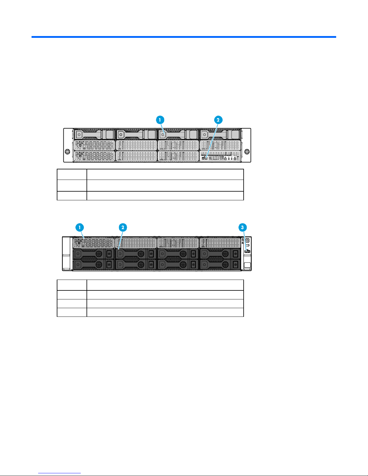
Component identification
Front panel components
• 4-bay LFF non-hot-plug drive model
Item Description
1
2
LFF non-hot-plug drives
USB 2.0 connector
• 8-bay LFF hot-plug drive model
Item Description
1
2
3
Box 1 LFF hot-plug drives
Box 2 LFF hot-plug drives
USB 3.0 connector
Component identification 7
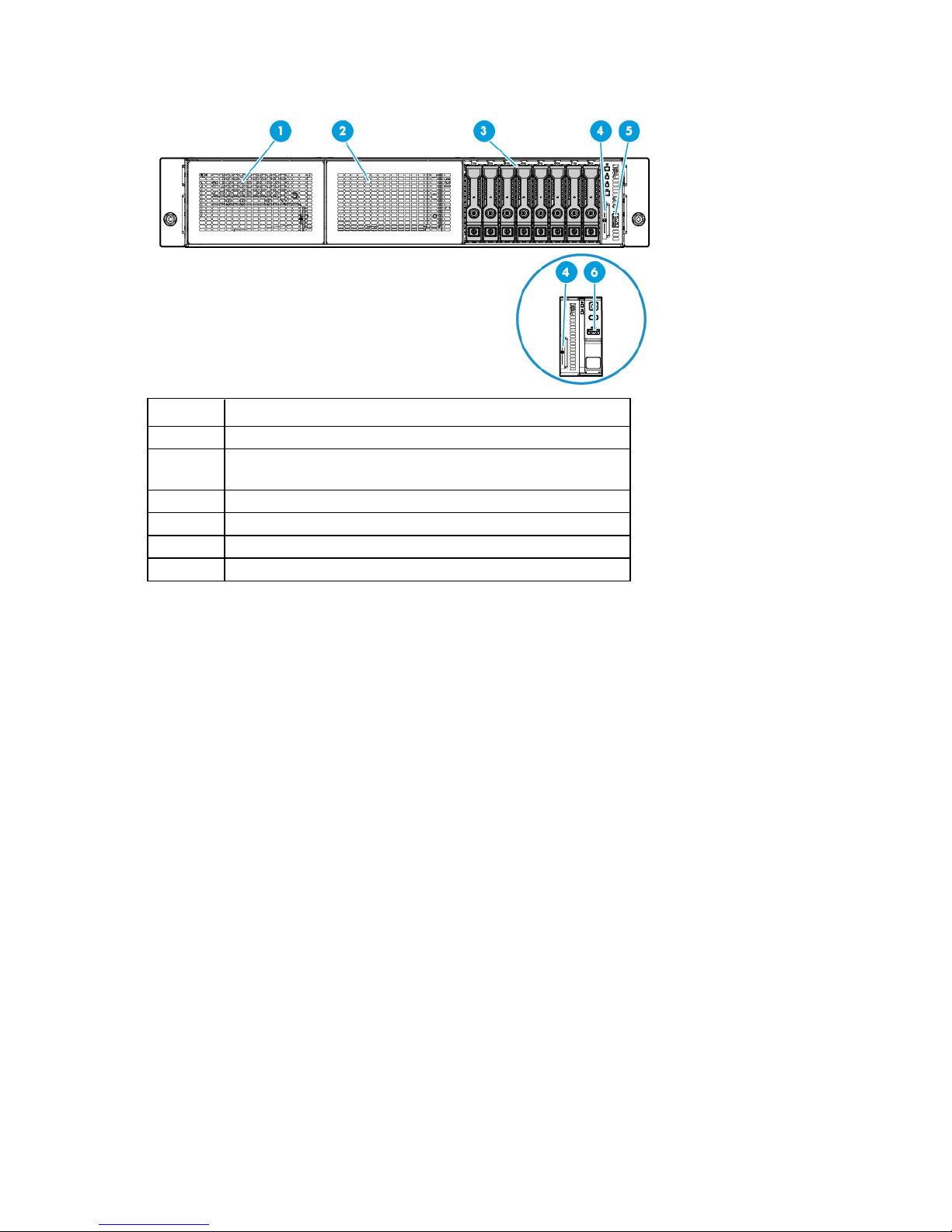
• 8-bay SFF hot-plug drive model
Item Description
1
2
3
4
5
6
HP Universal Media Bay (box 1, for the optical drive cage option)
8-bay SFF drive cage bay (box 2, for the second 8-bay SFF drive
cage option)
Box 3 SFF hot-plug drives
Serial label pull tab ("Serial label pull tab information" on page 8)
USB 2.0 connector (in servers using thumbscrew rack ears)
USB 3.0 connector (in servers using quick-release latch rack ears)
Serial label pull tab information
The vertically oriented serial label pull tab in the SFF chassis is double-sided. The following server labels are
attached to this pull tab:
• Left side—Server serial number label and the customer asset tag label
• Right side—Default iLO account information label and the QR code label
Use your mobile device to scan the QR code label to display the server mobile product page
(http://www.hp.com/qref/dl180gen9). This page contains links to server setup information, spare
part numbers, QuickSpecs, troubleshooting resources, and other useful product links.
In the LFF chassis, these server labels are attached on the front edge of the access panel instead.
Component identification 8
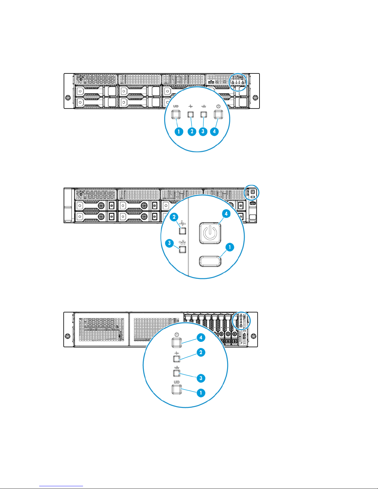
Front panel LEDs and buttons
• Front panel LEDs and buttons in an LFF chassis with thumbscrew rack ears
• Front panel LEDs and buttons in an LFF chassis with quick-release latch rack ears
• Front panel LEDs and buttons in an SFF chassis with thumbscrew rack ears
Component identification 9
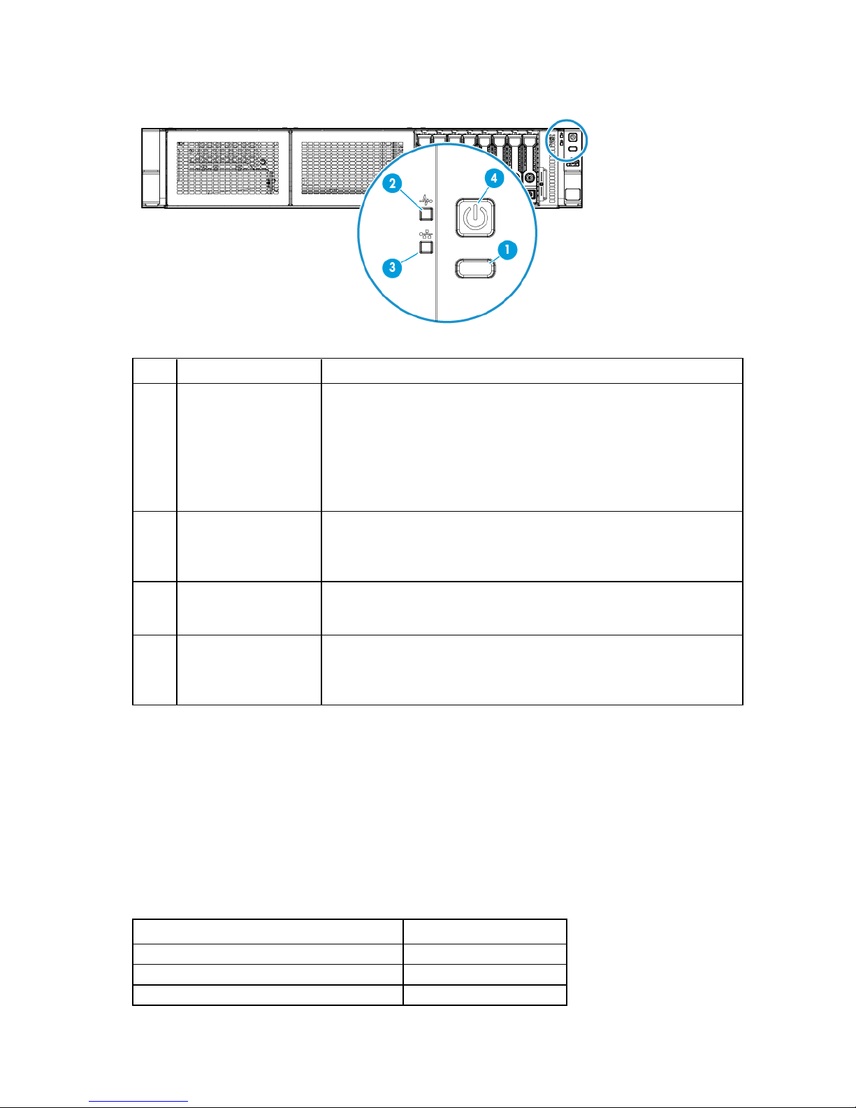
• Front panel LEDs and buttons in an SFF chassis with quick-release latch rack ears
•
•
•
Item Description Status
1
UID button/LED* Solid blue = Activated
Flashing blue:
1 Hz/cycle per sec = Remote management or firmware upgrade in
progress
4 Hz/cycle per sec = iLO manual reboot sequence initiated
8 Hz/cycle per sec = iLO manual reboot sequence in progress
Off = Deactivated
2
3
4
* When all four LEDs described in this table flash simultaneously, a power fault has occurred. For more information, see
"Front panel LED power fault codes (on page 10)."
** If the health LED indicates a degraded or critical state, review the system IML or use iLO to review the system health
status.
† Facility power is not present, power cord is not attached, no power supplies are installed, power supply failure has
occurred, or the front I/O cable is disconnected.
Health LED* Solid green = Normal
Flashing green (1 Hz/cycle per sec) = iLO is rebooting
Flashing amber = System degraded**
Flashing red (1 Hz/cycle per sec) = System critical**
NIC status LED* Solid green = Link to network
Flashing green (1 Hz/cycle per sec) = Network active
Off = No network activity
Power On/Standby
button and system power
LED*
Solid green = System on
Flashing green (1 Hz/cycle per sec) = Performing power on sequence
Solid amber = System in standby
Off = No power present†
Front panel LED power fault codes
The following table provides a list of power fault codes, and the subsystems that are affected. Not all power
faults are used by all servers.
Subsystem Front panel LED behavior
System board
Processor
Memory
1 flash
2 flashes
3 flashes
Component identification 10
Subsystem Front panel LED behavior
Hot-plug power supply 1
Riser board PCIe slots
FlexibleLOM
Removable HP Flexible Smart Array
controller/Smart SAS HBA controller
System board PCIe slots
Power backplane or storage backplane
Power supply
4 flashes
5 flashes
6 flashes
7 flashes
8 flashes
9 flashes
For more information, see "Front panel LEDs and buttons (on page 9)."
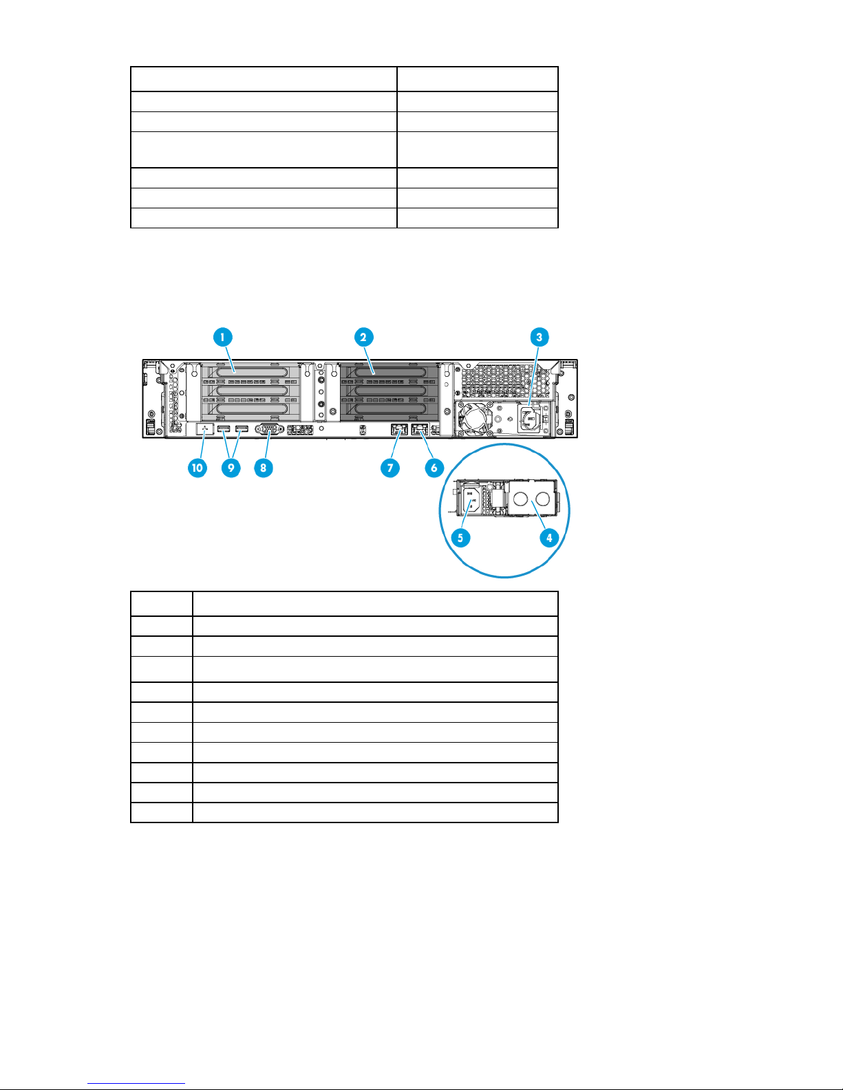
Rear panel components
Item Description
1
2
3
4
5
6
7
8
9
10
PCIe3 riser slots 1-3 (primary, associated with processor 1)
PCIe3 riser slots 4-6 (secondary, associated with processor 2)
Non-hot plug power supply
Hot-plug power supply bay 2
NIC connector 2
NIC 1/shared iLO connector
Video connector
USB 3.0 connectors
Dedicated iLO management connector (optional)
Component identification 11
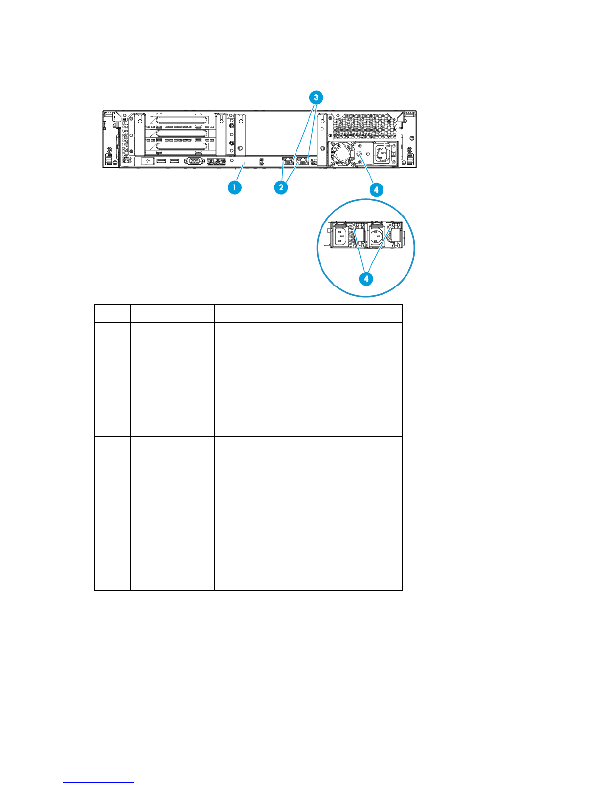
Rear panel LEDs
•
•
•
•
•
•
•
Item Description Status
1
UID LED Solid blue = Activated
Flashing blue:
1 Hz/cycle per sec = Remote management
or firmware upgrade in progress
4 Hz/cycle per sec = iLO manual reboot
sequence initiated
8 Hz/cycle per sec = iLO manual reboot
sequence in progress
Off = Deactivated
2
3
4
NIC link LED Green = Network link
Off = No network link
NIC activity LED Solid green = Link to network
Flashing green = Network active
Off = No network activity
Power supply LED Solid green = Normal
Off = One or more of the following conditions
exists:
Power is unavailable
Power supply failed
Power supply is in standby mode
Power supply error
PCIe riser board slot definitions
The server ships with a primary PCI riser cage installed and a secondary PCI riser cage blank. A second
processor is required to support installation in the secondary PCIe riser location.
Component identification 12
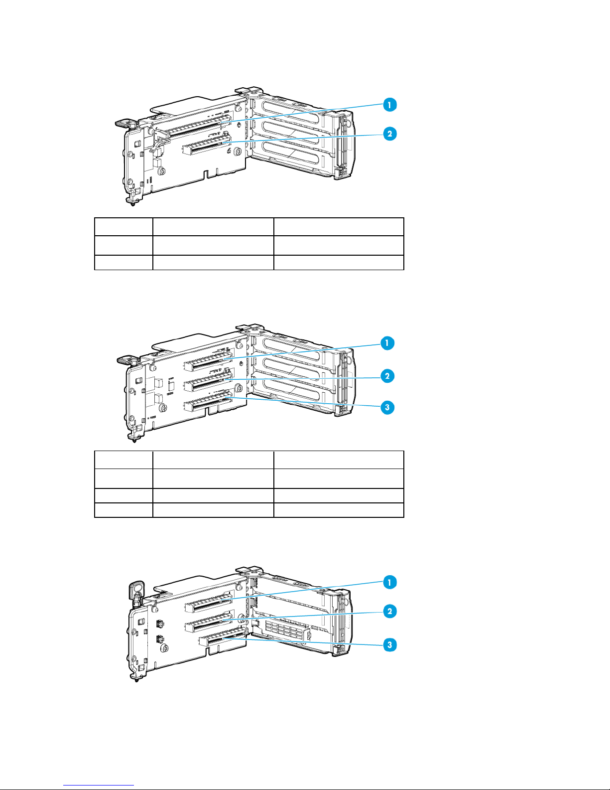
• Two-slot PCI riser cage assembly: Install in either the primary or secondary PCIe riser board connector
("PCI riser cage assembly options" on page 93).
Item Form factor Slot description
1
2
Full-height, full-length PCIe3 x16 (16, 8, 4, 1)
Full-height, half-length PCIe3 x8 (8, 4, 1)
• Three-slot PCI riser cage assembly: Install in either the primary or secondary PCIe riser board connector
("PCI riser cage assembly options" on page 93).
Item Form factor Slot description
1
2
3
Full-height, full-length PCIe3 x8 (8, 4, 1)
Full-height, half-length PCIe3 x8 (8, 4, 1)
Full-height, half-length PCIe3 x8 (8, 4, 1)
• FlexibleLOM riser cage assembly: Install in the secondary PCIe riser board connector ("FlexibleLOM
enablement option" on page 99).
Component identification 13
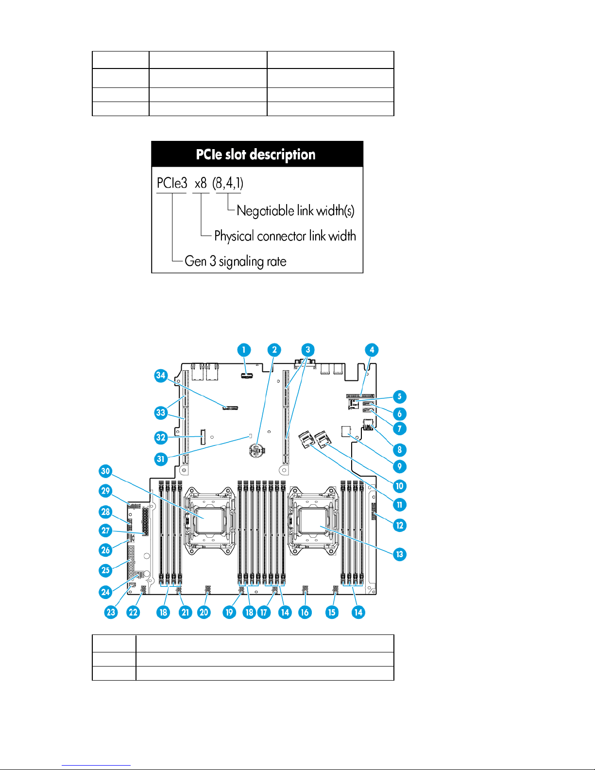
Item Form factor Slot description
1
Full-height, full-length PCIe3 x8 (8, 4, 1)
2
3
Full-height, half-length PCIe3 x8 (8, 4, 1)
FlexibleLOM PCIe3 x8
System board components
Item Description
1
2
FlexibleLOM sideband signal connector
System battery
Component identification 14

Processor 1 DIMM slots
Fan connector 3
Item Description
3
4
5
6
7
8
9
10
11
12
13
14
15
16
17
18
19
20
21
22
23
24
25
26
27
28
29
30
31
32
33
34
Primary PCIe riser board connectors ("PCIe riser board slot
definitions" on page 12)
Dedicated iLO module connector
microSD card slot
SATA connector 5 (for M.2 SSD 2)
SATA connector 4 (for M.2 SSD 1 or optical drive)
Internal USB 3.0 connector (for USB flash devices)
Front USB 3.0 connector (for the USB 3.0 connector on the right
quick-release latch rack ear)
Mini-SAS connector 1
Mini-SAS connector 2
Front I/O connector
Processor 1
Fan connector 5
Fan connector 4
Reserved
Processor 2 DIMM slots
Fan connector 2
Fan connector 1
Reserved
12-bay LFF drive identification signal connector
GPU power connector
24-pin power supply connector
HP Smart Storage Battery connector
20-pin drive power connector
16-pin power supply sideband signal connector
10-pin RPS connector
Processor 2
NMI header
TPM connector
Secondary PCIe riser board connectors ("PCIe riser board slot
definitions" on page 12)
System maintenance switch
Component identification 15
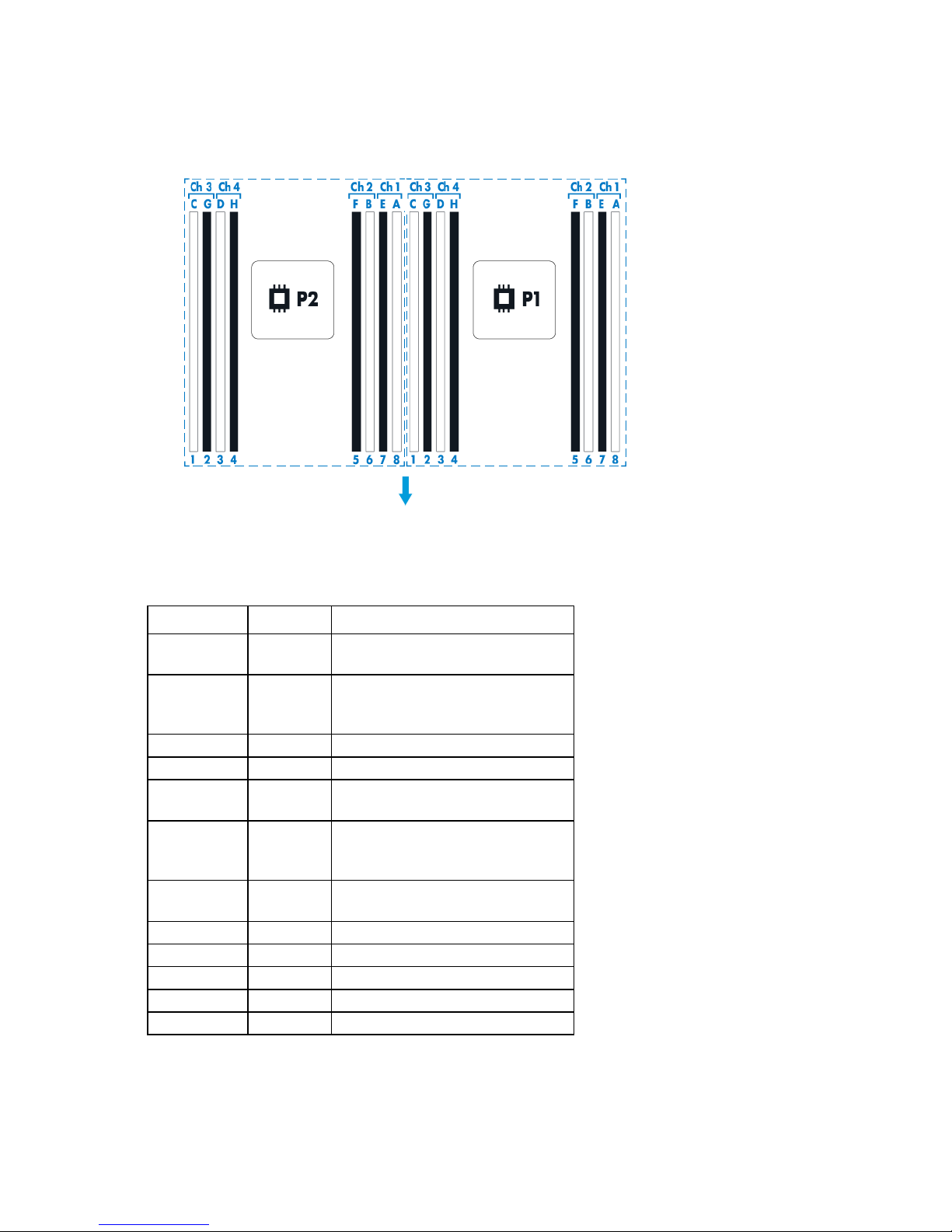
DIMM slot locations
—
Reserved
DIMM slots are numbered sequentially (1 through 8) for each processor. The supported AMP modes use the
letter assignments for population guidelines.
The arrow points to the front of the server.
System maintenance switch
Position Default Function
S1
S2
S3
S4
S5
S6
S7
S8
S9
S10
S11
S12
Off Off = iLO 4 security is enabled.
On = iLO 4 security is disabled.
Off Off = System configuration can be
changed.
On = System configuration is locked.
Off Reserved
Off Reserved
Off Off = Power-on password is enabled.
On = Power-on password is disabled.
Off Off = No function
On = ROM reads system configuration
as invalid.
Off Off = Set default boot mode to UEFI.
On = Set default boot mode to legacy.
— Reserved
— Reserved
— Reserved
— Reserved
To access the redundant ROM, set S1, S5, and S6 to on.
Component identification 16
When the system maintenance switch position 6 is set to the On position, the system is prepared to erase all
system configuration settings from both CMOS and NVRAM.
CAUTION: Clearing CMOS and/or NVRAM deletes configuration information. Be sure to
properly configure the server or data loss could occur.
IMPORTANT: Before using the S7 switch to change to Legacy BIOS Boot Mode, be sure the HP
Dynamic Smart Array B140i Controller is disabled. Do not use the B140i controller when the
server is in Legacy BIOS Boot Mode.
NMI functionality
An NMI crash dump creates a crash dump log before resetting a system which is not responding.
Crash dump log analysis is an essential part of diagnosing reliability problems, such as failures of operating
systems, device drivers, and applications. Many crashes freeze a system, and the only available action for
administrators is to restart the system. Resetting the system erases any information which could support
problem analysis, but the NMI feature preserves that information by performing a memory dump before a
system reset.
To force the system to invoke the NMI handler and generate a crash dump log, do one of the following:
• Use the iLO Virtual NMI feature.
• Short the NMI header ("System board components" on page 14).
For more information, see the HP website (http://www.hp.com/support/NMI).
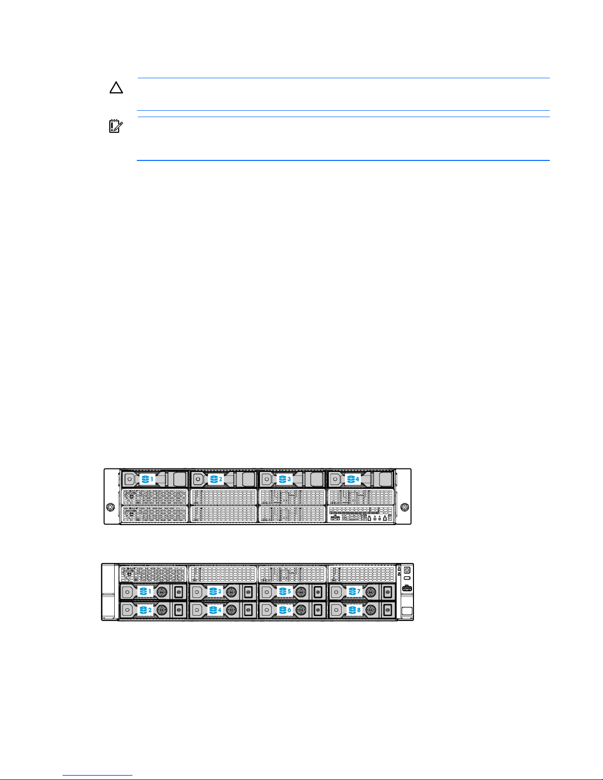
Drive numbering
The following images show the drive numbering for each of the supported drive configurations. For drive box
numbering information, see "Front panel components (on page 7)."
• 4-bay LFF non-hot-plug drive model
• 8-bay LFF hot-plug drive model
Component identification 17
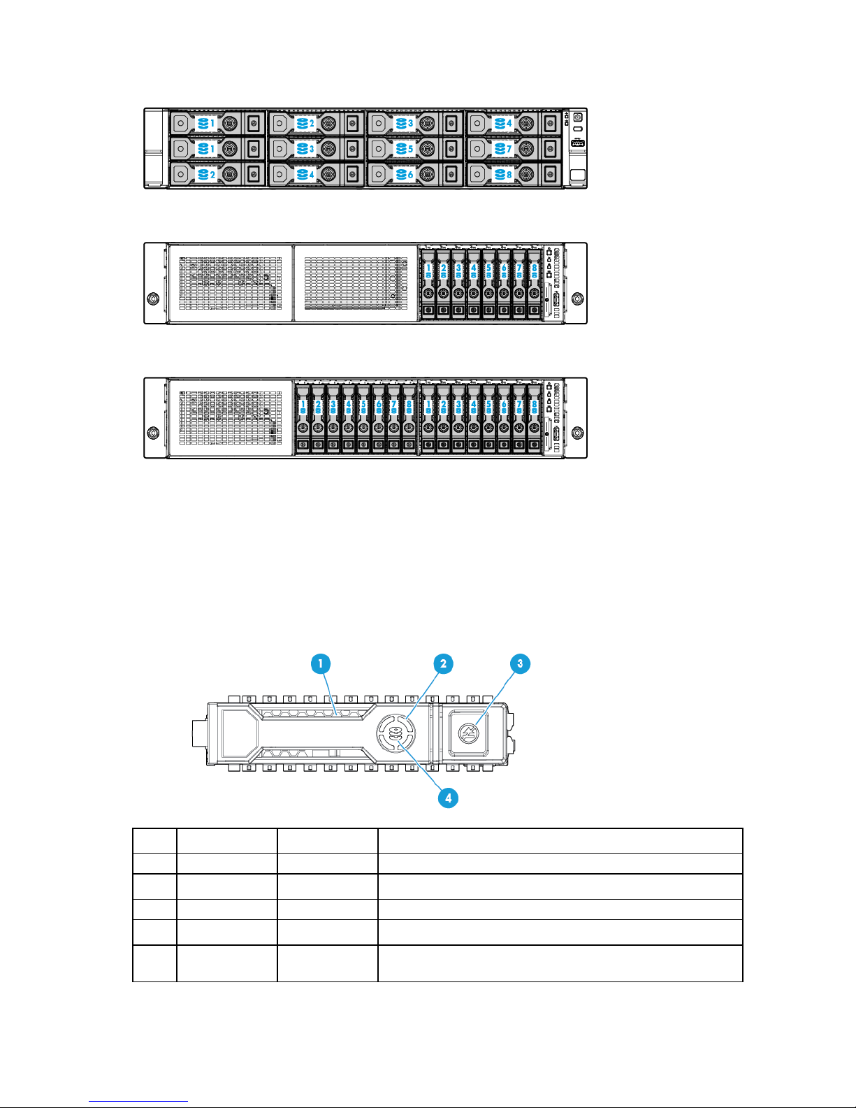
• 12-bay LFF hot-plug drive model
• 8-bay SFF hot-plug drive model
• 16-bay SFF hot-plug drive model
HP SmartDrive LED definitions
HP SmartDrives are the latest HP drive technology, and they are supported beginning with ProLiant Gen8
servers and server blades. The HP SmartDrive is not supported on earlier generation servers and server
blades. Identify an HP SmartDrive by its carrier, shown in the following illustration.
When a drive is configured as a part of an array and connected to a powered-up controller, the drive LEDs
indicate the condition of the drive.
Item LED Status Definition
1
2
3
Locate Solid blue The drive is being identified by a host application.
Flashing blue The drive carrier firmware is being updated or requires an update.
Activity ring Rotating green Drive activity
Off No drive activity
Do not remove Solid white Do not remove the drive. Removing the drive causes one or more of
the logical drives to fail.
Component identification 18
Item LED Status Definition
4
Drive status Solid green The drive is a member of one or more logical drives.
The blue Locate LED is behind the release lever and is visible when illuminated.
IMPORTANT: The HP Dynamic Smart Array B140i Controller is only available in UEFI Boot Mode.
Off Removing the drive does not cause a logical drive to fail.
Flashing green The drive is rebuilding or performing a RAID migration, strip size
migration, capacity expansion, or logical drive extension, or is
erasing.
Flashing
amber/green
Flashing amber The drive is not configured and predicts the drive will fail.
Solid amber The drive has failed.
Off The drive is not configured by a RAID controller.
The drive is a member of one or more logical drives and predicts
the drive will fail.
It cannot be enabled in Legacy BIOS Boot Mode. If the B140i controller is disabled, drives
connected to the system board Mini-SAS connectors operate in AHCI or Legacy mode. Under this
condition:
• The drives cannot be a part of a hardware RAID or a logical drive.
• The Locate, Drive status, and Do not remove LEDs of the affected drives are disabled.
Use BIOS/Platform Configuration (RBSU) in the UEFI System Utilities ("HP UEFI System Utilities" on
page 133) to enable or disable the B140i controller (System Configuration → BIOS/Platform
Configuration (RBSU) → System Options → SATA Controller Options → Embedded SATA
Configuration).
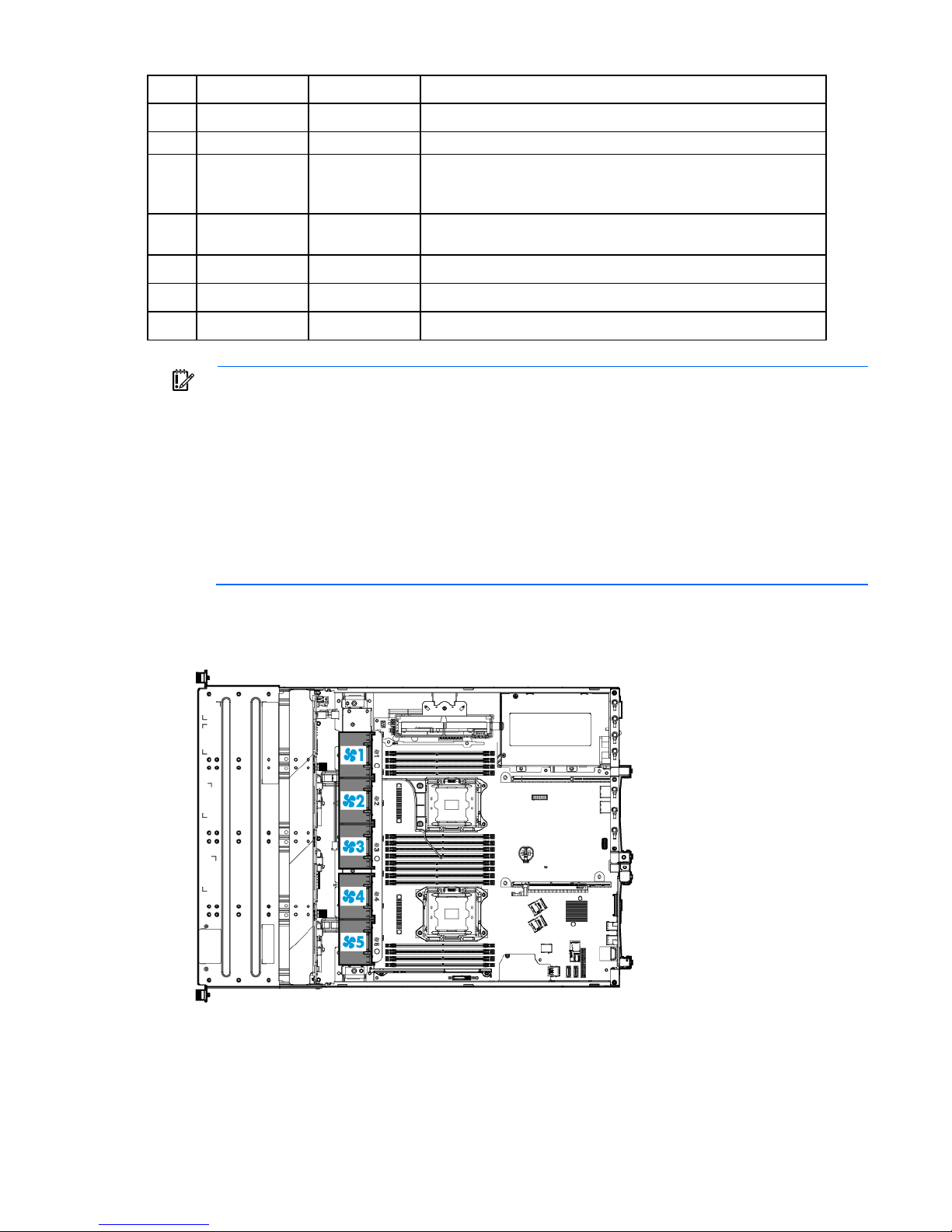
Fan locations
Component identification 19

Operations
Power up the server
To power up the server, press the Power On/Standby button.
Power down the server
Before powering down the server for any upgrade or maintenance procedures, perform a backup of critical
server data and programs.
IMPORTANT: When the server is in standby mode, auxiliary power is still being provided to the
To power down the server, use one of the following methods:
• Press and release the Power On/Standby button.
• Press and hold the Power On/Standby button for more than 4 seconds to force the server to enter
• Use a virtual power button selection through iLO 4.
system.
This method initiates a controlled shutdown of applications and the OS before the server enters standby
mode.
standby mode.
This method forces the server to enter standby mode without properly exiting applications and the OS.
If an application stops responding, you can use this method to force a shutdown.
This method initiates a controlled remote shutdown of applications and the OS before the server enters
standby mode.
Before proceeding, verify the server is in standby mode by observing that the system power LED is amber.
Extend the server from the rack
WARNING: To reduce the risk of personal injury or equipment damage, be sure that the rack is
1. If the rear panel cables are not secured by a cable management arm, do the following:
adequately stabilized before extending a component from the rack.
a. Power down the server (on page 20).
b. Disconnect all peripheral cables from the server.
c. Disconnect each power cord from the server.
Operations 20
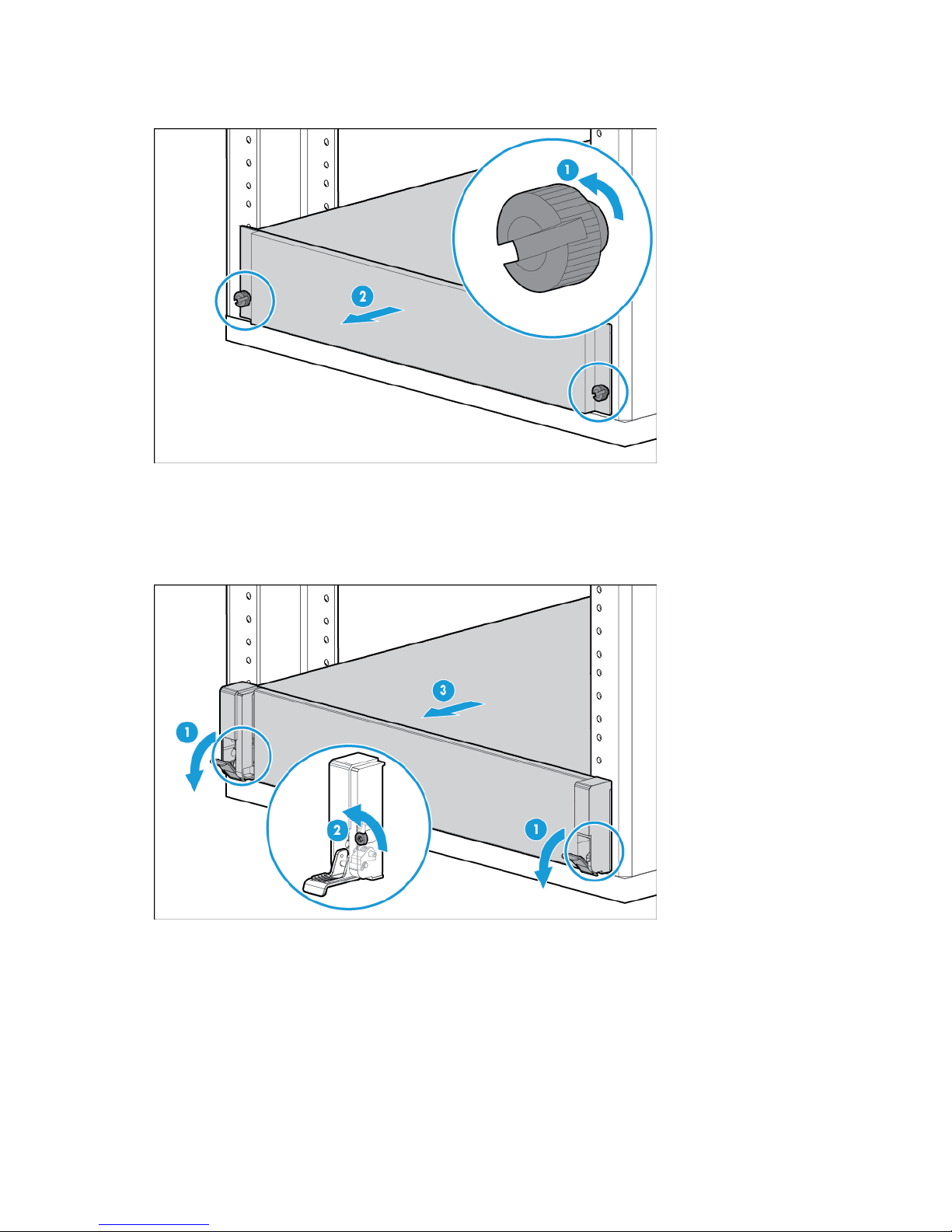
2. In a server that uses thumbscrew rack ears, loosen the captive thumbscrews that secure the server
faceplate to the front of the rack, and then slide the server out of the rack.
3. In a server that uses quick-release latch rack ears:
a. Open the latches on both sides of the server.
b. If necessary, use a T-25 Torx screwdriver to loosen the shipping screws.
c. Slide the server out of the rack.
Operations 21
4. After performing the installation or maintenance procedure, slide the server back into the rack, and then
press the server firmly into the rack to secure it in place.
5. Do one of the following:
o In a server that uses thumbscrew rack ears, tighten the captive thumbscrews.
o In a server that uses quick-release latch rack ears, if necessary, tighten the shipping screws.
6. If the rear panel cables were disconnected because a cable management arm is not in use, do the
following:
a. Connect each power cord to the server.
b. Connect all peripheral cables to the server.
c. Power up the server (on page 20).
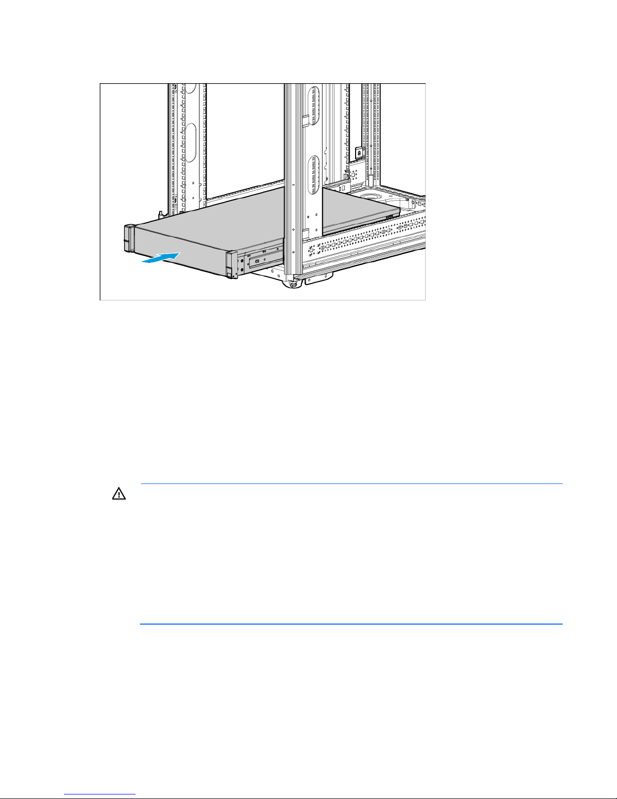
Remove the server from the rack
WARNING: This server is very heavy. To reduce the risk of personal injury or damage to the
equipment:
• Observe local occupational health and safety requirements and guidelines for manual
material handling.
• Get help to lift and stabilize the product during installation or removal, especially when the
product is not fastened to the rails. HP recommends that a minimum of two people are required
for all rack server installations. A third person may be required to help align the server if the
server is installed higher than chest level.
• Use caution when installing the server in or removing the server from the rack; it is unstable
when not fastened to the rails.
To remove the server from an HP, Compaq-branded, Telco, or a third-party rack:
1. Power down the server (on page 20).
2. Extend the server on the rack rails until the server rail-release latches engage.
3. Disconnect all peripheral cables from the server.
4. Disconnect each power cord from the server.
Operations 22
5. Remove the server from the rack.
For instructions on how to extend or remove the server from the rack, see the documentation that ships
with the rack rail system.
6. Place the server on a sturdy, level surface.
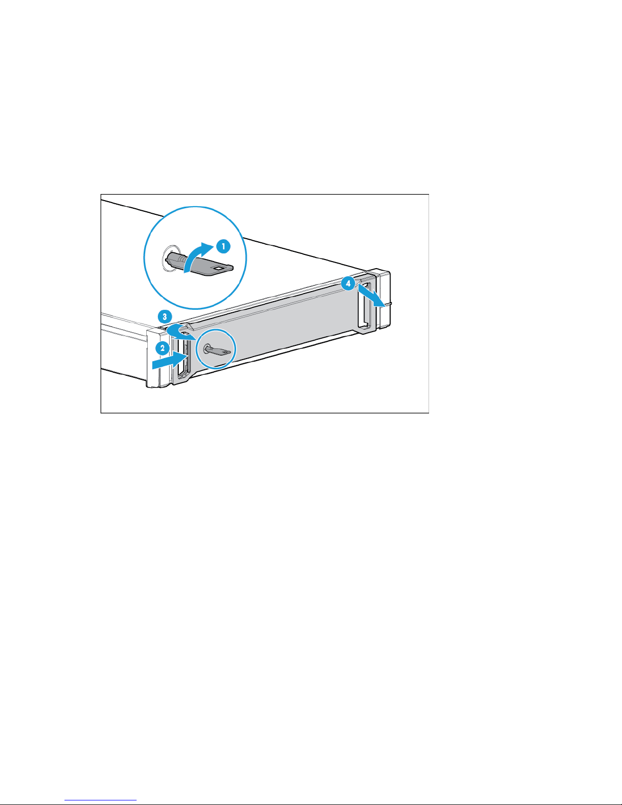
Remove the security bezel (optional)
To access the front panel components, unlock and then remove the security bezel. The security bezel is only
supported in servers that are using the quick-release latch rack ears.
Operations 23
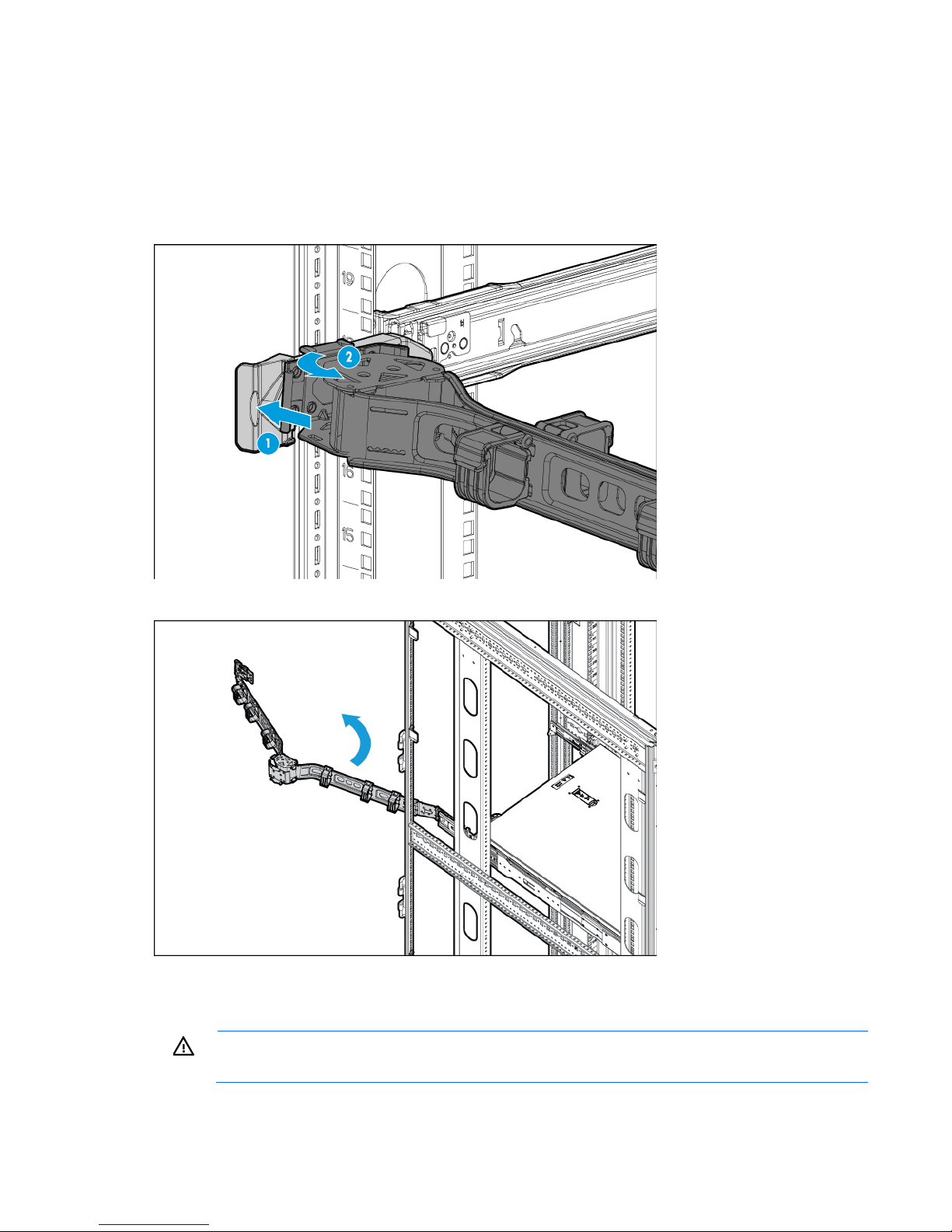
Access the product rear panel
Opening the cable management arm
To access the server rear panel:
1. Release the cable management arm.
2. Open the cable management arm. The cable management arm can be right-mounted or left-mounted.
Remove the access panel
WARNING: To reduce the risk of personal injury from hot surfaces, allow the drives and the
internal system components to cool before touching them.
Operations 24
CAUTION: To prevent damage to electrical components, take the appropriate anti-static
precautions before beginning any installation, removal, or replacement procedure. Improper
grounding can cause electrostatic discharge.
CAUTION: Do not operate the server for long periods with the access panel open or removed.
Operating the server in this manner results in improper airflow and improper cooling that can
lead to thermal damage.
To remove the component:
1. Power down the server (on page 20).
2. If you are performing a non-hot-plug procedure, remove all power:
a. Disconnect each power cord from the power source.
b. Disconnect each power cord from the server.
3. Do one of the following:
o Extend the server from the rack (on page 20).
o Remove the server from the rack (on page 22).
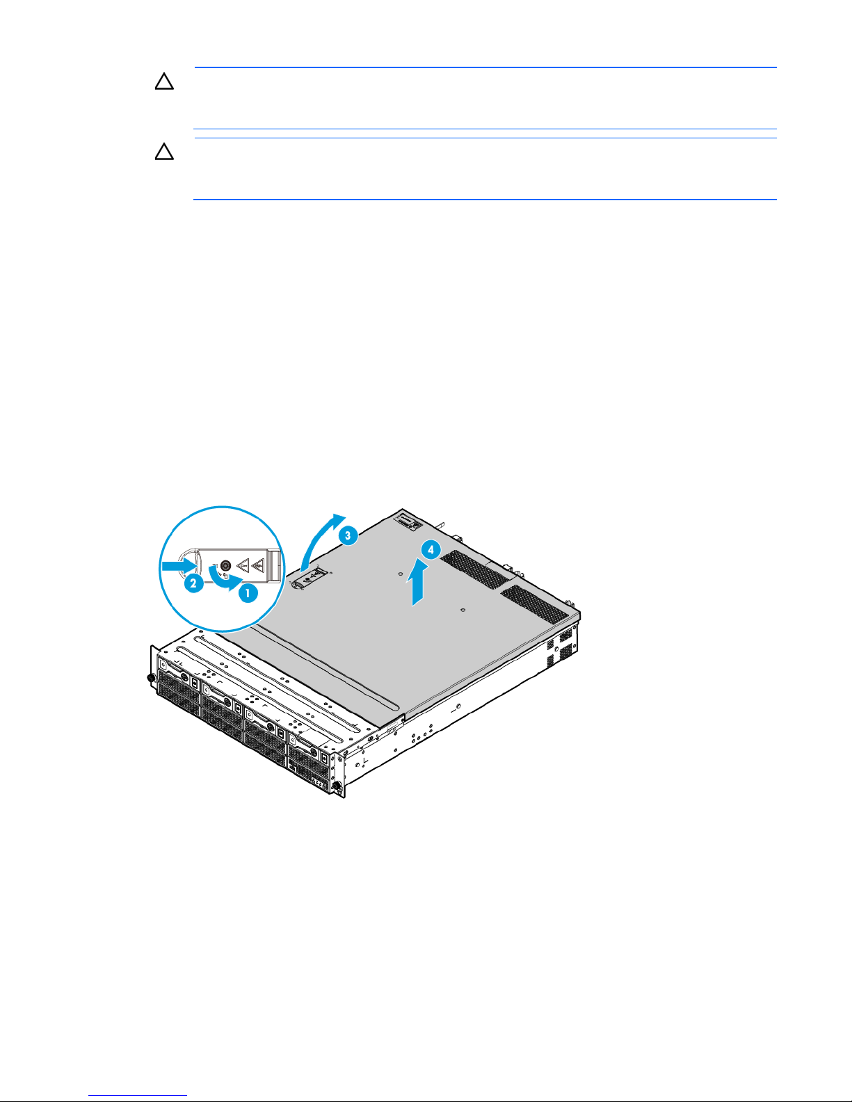
4. If the locking latch is locked, use a T-15 Torx screwdriver to unlock the latch.
5. Open the locking latch.
The access panel slides back, releasing it from the chassis.
6. Lift and remove the access panel.
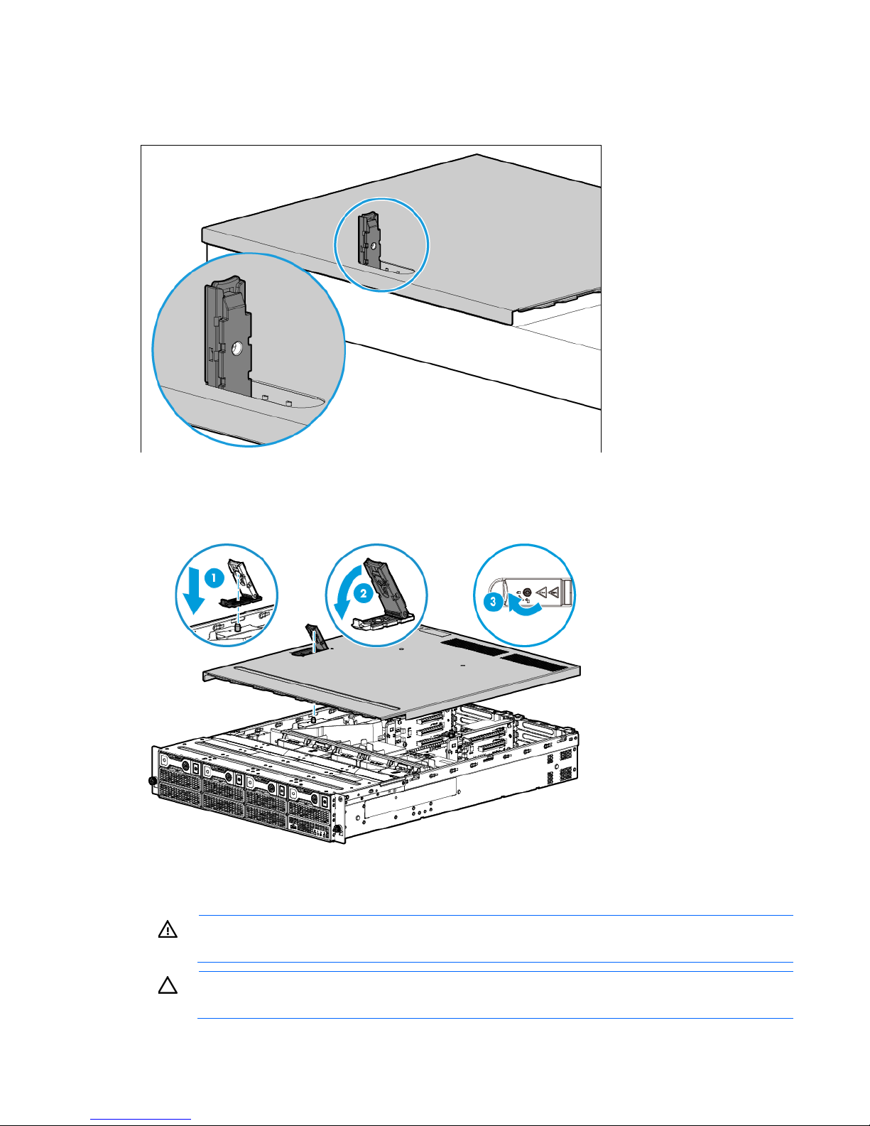
Turn the access panel over to locate the HP ProLiant DL180 Gen9 Server hood label. This label provides
convenient access to component identification, LED status indicators, and system maintenance switch settings
information.
Operations 25
Install the access panel
1. Ensure that the access panel latch is in the open position.
2. Align the hole in the access panel latch with the guide pin on the chassis.
3. Close the access panel latch. The access panel slides to a closed position.
4. Use a T-15 Torx screwdriver to tighten the access panel latch screw.
Remove the PCI riser cages
WARNING: To reduce the risk of personal injury from hot surfaces, allow the drives and the
internal system components to cool before touching them.
CAUTION: To prevent damage to the server or expansion boards, power down the server, and
disconnect all power cords before removing or installing the PCI riser cage.
Operations 26
To remove the component:
1. Power down the server (on page 20).
2. Remove all power:
a. Disconnect each power cord from the power source.
b. Disconnect each power cord from the server.
3. Do one of the following:
o Extend the server from the rack (on page 20).
o Remove the server from the rack (on page 22).
4. Remove the access panel (on page 24).
5. If the server was just extended from the rack and expansion boards with external cabling are installed
on the PCI riser cage, disconnect all cables from the expansion boards to completely remove the cage
from the server.
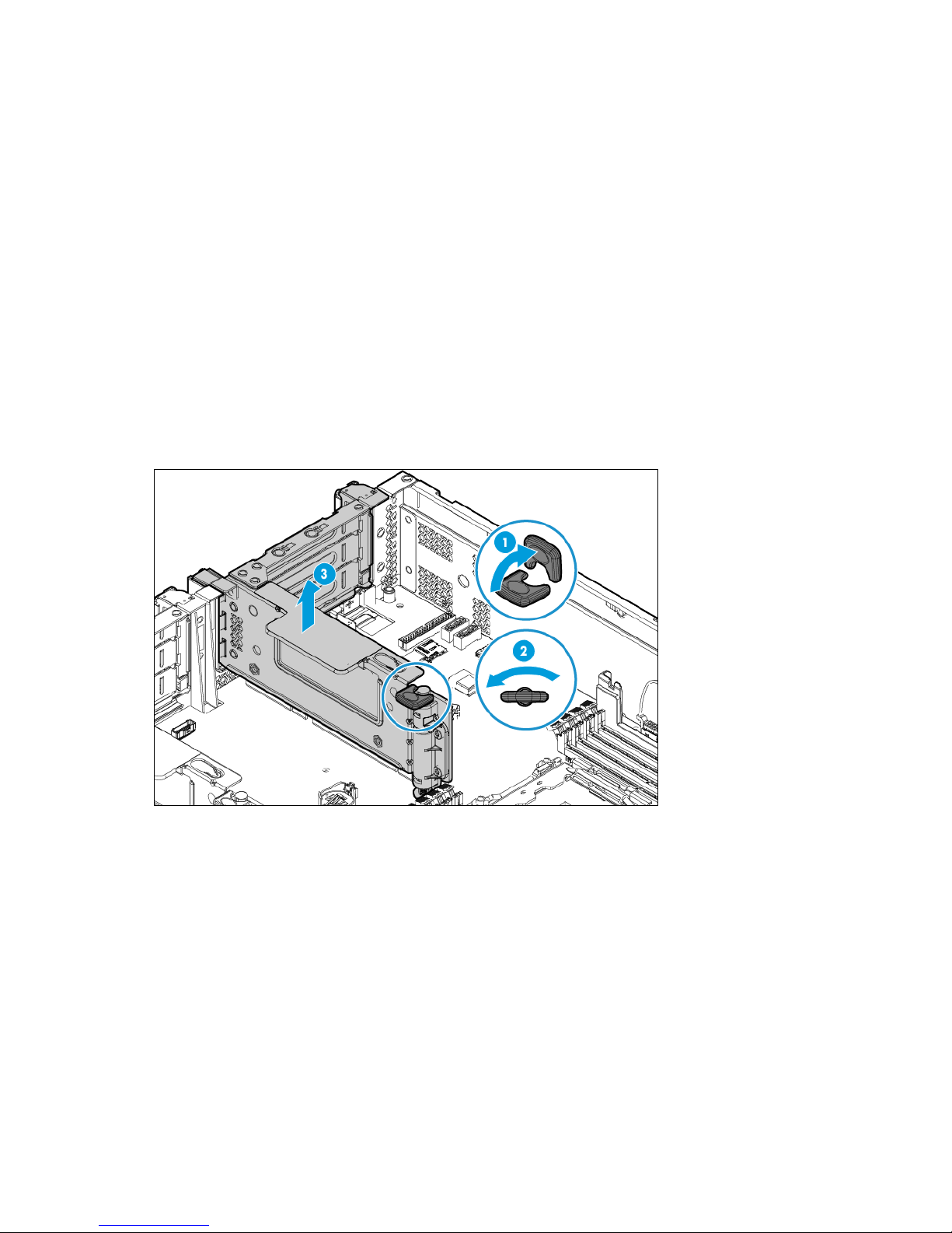
6. Lift the release tab, and then rotate it 180° counterclockwise.
7. Grasp the PCI riser cage at the touch points and lift it out of the chassis.
o Primary PCI riser cage
Operations 27
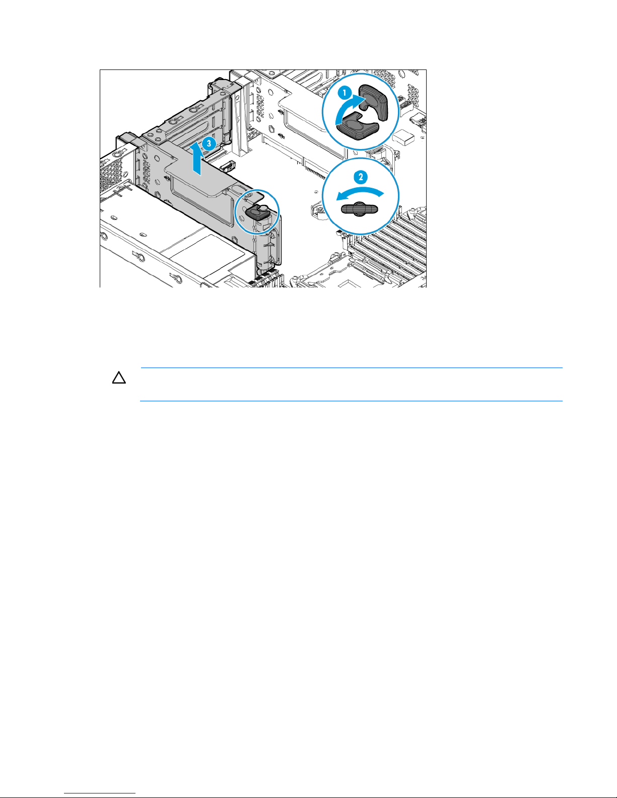
o Secondary PCI riser cage
8. If expansion boards with internal cabling are installed on the PCI riser cage, disconnect all internal
cables from the expansion boards to completely remove the cage from the server.
Install the PCI riser cages
CAUTION: To prevent damage to the server or expansion boards, power down the server, and
To install the component:
1. If cabled expansion boards are installed on the PCI riser cage, connect all necessary internal cabling to
2. Align the riser board with the corresponding connectors on the system board, and then press down the
3. Push down the release tab, rotate it 180° clockwise, and then press it flat on the PCI riser cage.
disconnect all power cords before removing or installing the PCI riser cage.
the expansion boards.
For more information on these cabling requirements, see the documentation that ships with the option.
PCI riser cage.
Operations 28
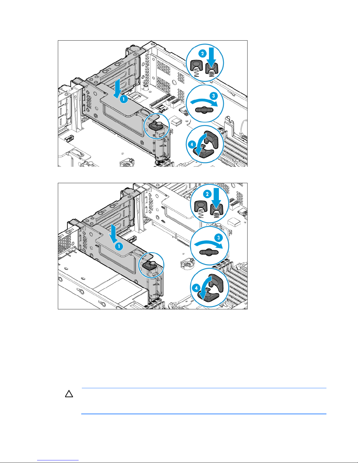
o Primary PCI riser cage
o Secondary PCI riser cage
4. Install the access panel (on page 26).
5. Do one of the following:
o Slide the server into the rack.
o Install the server into the rack ("Installing the server into the rack" on page 36).
6. Power up the server (on page 20).
Remove the air baffle
CAUTION: For proper cooling, do not operate the server without the access panel, baffles,
expansion slot covers, or blanks installed. If the server supports hot-plug components, minimize
the amount of time the access panel is open.
Operations 29
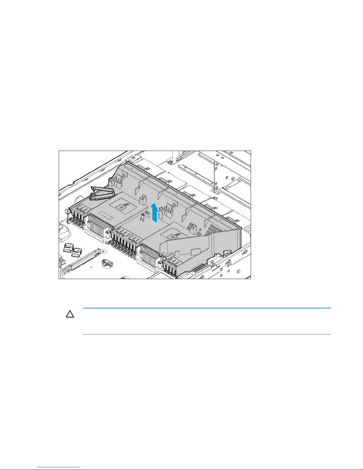
To remove the component:
1. Power down the server (on page 20).
2. Remove all power:
a. Disconnect each power cord from the power source.
b. Disconnect each power cord from the server.
3. Do one of the following:
o Extend the server from the rack (on page 20).
o Remove the server from the rack (on page 22).
4. Remove the access panel (on page 24).
5. If a full-length expansion board is installed on a PCI riser cage, remove the riser cage ("Remove the PCI
riser cages" on page 26).
6. Remove the air baffle.
Install the air baffle
CAUTION: For proper cooling, do not operate the server without the access panel, baffles,
expansion slot covers, or blanks installed. If the server supports hot-plug components, minimize
the amount of time the access panel is open.
Operations 30
 Loading...