

Page 1

HP ProLiant DL180 Server
Software Configuration Guide
Part number: 451525-001
First edition: June 2007
Page 2

Legal notices
© Copyright 2007 Hewlett-Packard Development Company, L.P.
The information contained herein is subject to change without notice. The only warranties for HP products and services are
set forth in the express warranty statements accompanying such products and services. Nothing herein should be construed
as constituting an additional warranty. HP shall not be liable for technical or editorial errors or omissions contained herein.
Microsoft, Windows, and Windows NT are U.S. registered trademarks of Microsoft Corporation. Windows Server 2003 is
a trademark of Microsoft Corporation. Intel, Pentium, and Itanium are trademarks or registered trademarks of Intel
Corporation or its subsidiaries in the United States and other countries. UNIX is a registered trademark of The Open Group.
Page 3

Contents
System BIOS configuration ......................................................................................................................5
System BIOS overview.............................................................................................................................. 5
AMIBIOS software ................................................................................................................................... 5
AMIBIOS Setup Utility............................................................................................................................... 5
Accessing the Setup Utility.................................................................................................................... 6
Navigating through the Setup Utility ...................................................................................................... 7
Setup Utility menus.............................................................................................................................. 8
Security menu................................................................................................................................... 34
Recording custom Setup values ........................................................................................................... 41
Loading system defaults ..................................................................................................................... 41
Clearing CMOS ............................................................................................................................... 41
Power-On Self Test (POST) )..................................................................................................................... 41
POST error indicators ........................................................................................................................ 42
POST beep codes ............................................................................................................................. 43
POST-related troubleshooting.............................................................................................................. 49
Reprogramming the BIOS with the crisis recovery jumper ............................................................................ 50
NOS installation ..................................................................................................................................51
Supported NOS..................................................................................................................................... 51
NOS pre-installation procedure ............................................................................................................... 51
Hardware setup................................................................................................................................ 51
BIOS update .................................................................................................................................... 52
Installing Microsoft Windows NOS .......................................................................................................... 52
Pre-installation instructions .................................................................................................................. 52
Installation flow................................................................................................................................. 52
Section 1. Creating the driver diskettes ................................................................................................ 52
Section 2. Installing Windows NOS .................................................................................................... 53
Section 3. Completing the installation.................................................................................................. 54
Section 4. Configuring the system ....................................................................................................... 55
Section 5. Configuring the network ..................................................................................................... 57
Section 6. Installing additional HP accessories...................................................................................... 59
Installing Red Hat Enterprise Linux NOS.................................................................................................... 59
Installation flow................................................................................................................................. 59
Pre-installation instructions .................................................................................................................. 59
Red Hat Enterprise Linux 3 installation ................................................................................................. 59
Red Hat Enterprise Linux 4 installation ................................................................................................. 61
Installing SUSE Linux Enterprise Server NOS.............................................................................................. 64
Installation flow................................................................................................................................. 64
Pre-installation instructions .................................................................................................................. 64
SUSE Linux Enterprise Server 9 installation ........................................................................................... 64
SUSE Linux Enterprise Server 10 Installation ......................................................................................... 65
Installing Sun Solaris 10 ......................................................................................................................... 67
Pre-installation instructions .................................................................................................................. 67
Installation flow................................................................................................................................. 67
Sun Solaris 10 installation.................................................................................................................. 67
Server management.............................................................................................................................. 71
Pre- and post-installation procedures......................................................................................................... 71
Pre-installation procedures.................................................................................................................. 71
Contents 3
Page 4

Post-installation procedures................................................................................................................. 72
Configuring the BMC ............................................................................................................................. 72
Index ..................................................................................................................................................74
Contents 4
Page 5

System BIOS configuration
This chapter describes the basic functions of the AMIBIOS software.
System BIOS overview
A Basic Input/Output System, or BIOS, is a set of programs permanently stored in an EEPROM
chipset (U70) located on the system board. These programs serve as an interface between the server’s
hardware components and its operating system. This ProLiant server features the AMIBIOS software—
a ROM BIOS-based diagnostic tool that monitors system activity and performs constant hardware
testing to ensure proper system operation.
AMIBIOS software
The AMIBIOS software serves three functions:
• Configure the system settings via the AMIBIOS Setup Utility
Using the Setup Utility, you can install, configure, and optimize the hardware devices on your
system (such as clock, memory, and hard drives).
• Initialize hardware at boot via POST routines
At power-on or reset, the software performs Power-On Self Test (POST) routines to test system
resources and run the operating system.
• Perform run-time routines
Using the software, perform basic hardware routines that can be called from DOS and Windows
applications.
AMIBIOS Setup Utility
NOTE: For ease of reading, the AMIBIOS Setup Utility will be referred to as “Setup” or “Setup
Utility” in this guide. Also, the screenshots used in this guide display default system values. These
values may not be the same as those in your server.
The AMIBIOS Setup Utility is a hardware configuration program built into the server BIOS. Because
most systems are already properly configured and optimized, there is normally no need to run this
utility.
, You need to run this utility under the following conditions:
• When changing the system configuration including:
○ Setting the system time and date
○ Configuring the hard drives
○ Specifying the boot device sequence
○ Configuring the power management modes
○ Setting up system passwords or making other changes to the security setup
Contents 5
Page 6
• When a configuration error is detected by the system and you are prompted by a Run Setup
message to make changes to the BIOS settings.
NOTE: If you repeatedly receive “Run Setup” messages, the battery located on the system board
(XBAT1) may be defective. In this case, the system cannot retain configuration values in CMOS. Ask
a qualified technician for assistance.
The Setup Utility loads the configuration values in a battery-backed nonvolatile memory called CMOS
RAM. This memory area is not part of the system RAM, which allows configuration data to be
retained when power is turned off. The values take effect when the system is booted. POST uses these
values to configure the hardware. If the values and the actual hardware do not agree, POST
generates an error message. You must run the Setup Utility to change the BIOS settings from the
default or current configuration.
Accessing the Setup Utility
1. Turn on the monitor and the server.
If the server is already turned on, save your data and exit all open applications, then restart the
server.
During POST, press F10. If you fail to press F10 before POST is completed, you need to restart
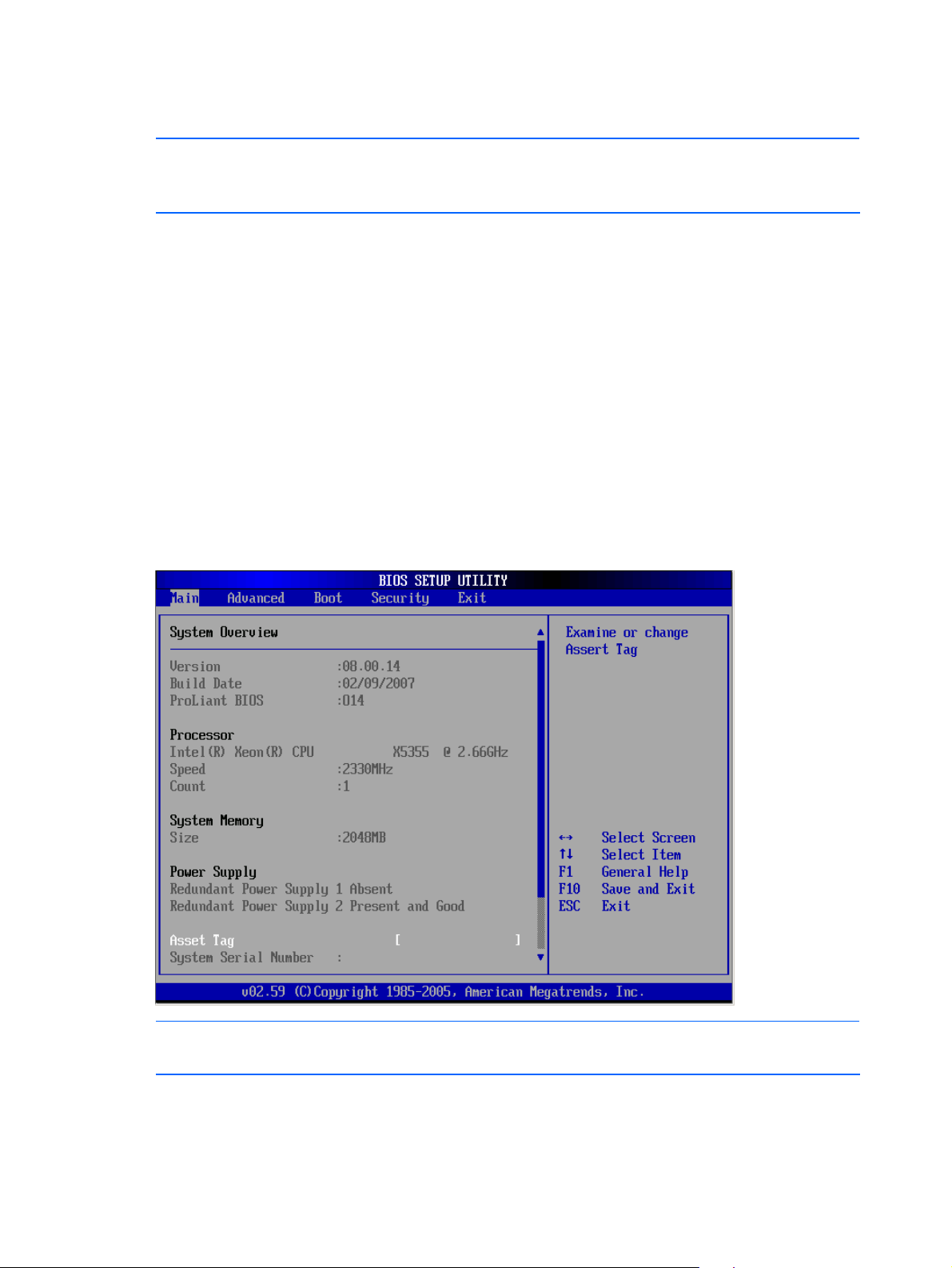
the server and repeat this step. The first page displayed is the Main menu. Use the left (←) and
right (→) arrow keys to move between selections on the menu bar.
Figure 1 Main menu
NOTE: System Serial Number and Asset Tag are not updated even when CMOS defaults are
loaded or CMOS is cleared.
Contents 6
Page 7

Navigating through the Setup Utility
Use the keys listed in the legend bar on the bottom of the Setup screen to access the various menu
and submenu screens of the Setup Utility. Figure 1 in the previous section shows the legend bar at the
bottom of the Main menu. Table 1 lists these legend keys and their respective functions.
Table 1
Setup Utility navigation keys
Key Function
← and → Move between selections on the menu bar.
↑ and ↓ Move the cursor to the field you want.
The currently selected field is highlighted. The right side of each menu screen displays the Item
Specific Help panel. This panel displays the help text for the selected field. It updates as you move
the cursor to each field.
<+>, <–> Select a value for the currently selected field if it is user-configurable.
Press the (+) or (-) keys repeatedly to scroll through each value one at a time, or press the Enter
key to choose from a pop-up menu that displays all possible values at once.
A parameter that is enclosed in square brackets [ ] is user-configurable.
Grayed-out parameters are not user-configurable for one of the following reasons:
• The field value is auto-configured or auto-detected.
• The field value is informational only.
• The field is password-protected.
Enter Select a field value or display a submenu screen.
►
Indicates a submenu field.
To view a submenu screen, use the ↑ and ↓ keys to move the cursor to the submenu you want,
then press Enter.
Esc When you press this key:
• On a primary menu screen, the Exit menu displays.
• On a submenu screen, the previous screen displays.
• On a pop-up menu, closes the pop-up without making a selection.
F1 Displays the General Help screen. See Figure 2.
The General Help screen describes other Setup navigation keys that are not displayed on the
legend bar.
F9 Loads the default system values.
F10 Saves all changes to settings and closes the Setup Utility.
Contents 7
Page 8
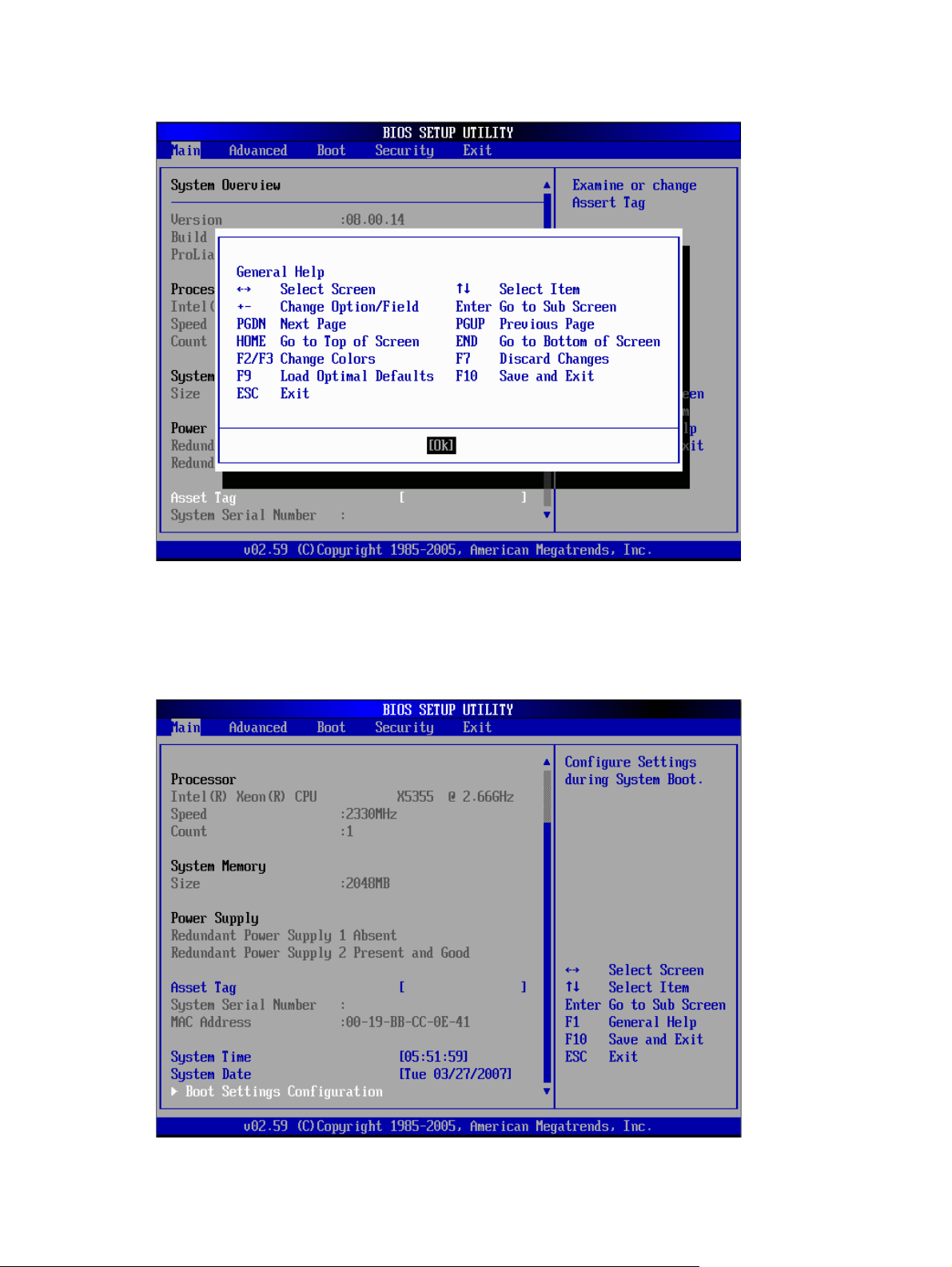
Figure 2 General Help Screen
Setup Utility menus
Main Menu
Figure 3 Main Menu
Contents 8
Page 9
NOTE: The time is in 24-hour format. For example, 5:30 A.M. appears as 05:30:00, and 5:30,
P.M. as 17:30:00. If you clear CMOS, setup time and date values will be 00:00:00 and
02/29/2006
.
Table 2
Main menu fields
Field Description
System Overview Displays the system ROM Version, the date when the Setup utility was created and
identification number.
Processor Displays the CPU version, speed and count.
System Memory Displays the amount of conventional memory detected during POST.
Power Supply Displays the redundant power supply.
Asset Tag Enter the server asset tag.
System Serial
Number
System Time Adjusts the system time.
System Date Adjusts the system date.
Boot Settings
Configuration
Enter the server serial number. The serial number is indicated on the serial number label pull
tab on the front panel.
Sets which options to run during system boot up. Press Enter to access the related submenu.
For details on the submenu options, see the “Boot Settings Configuration submenu” section on
page 10.
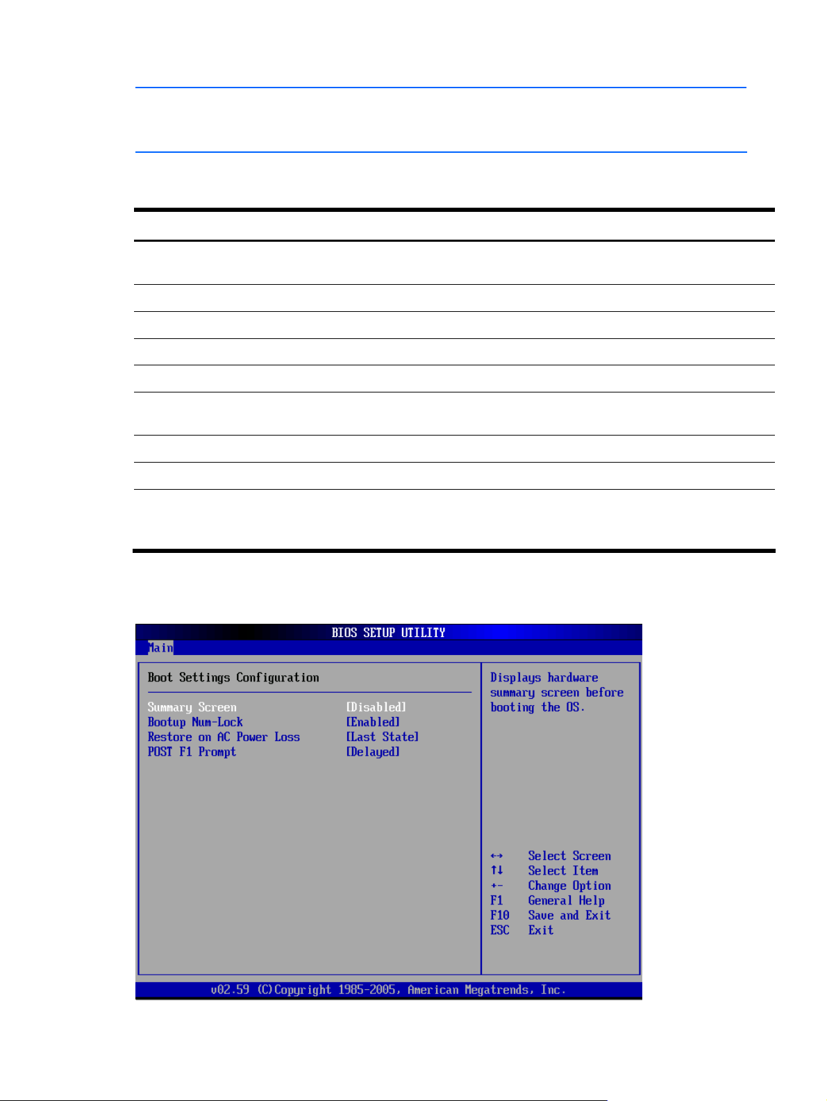
Boot Settings Configuration submenu
Figure 4 Boot Settings Configuration submenu
Contents 9
Page 10
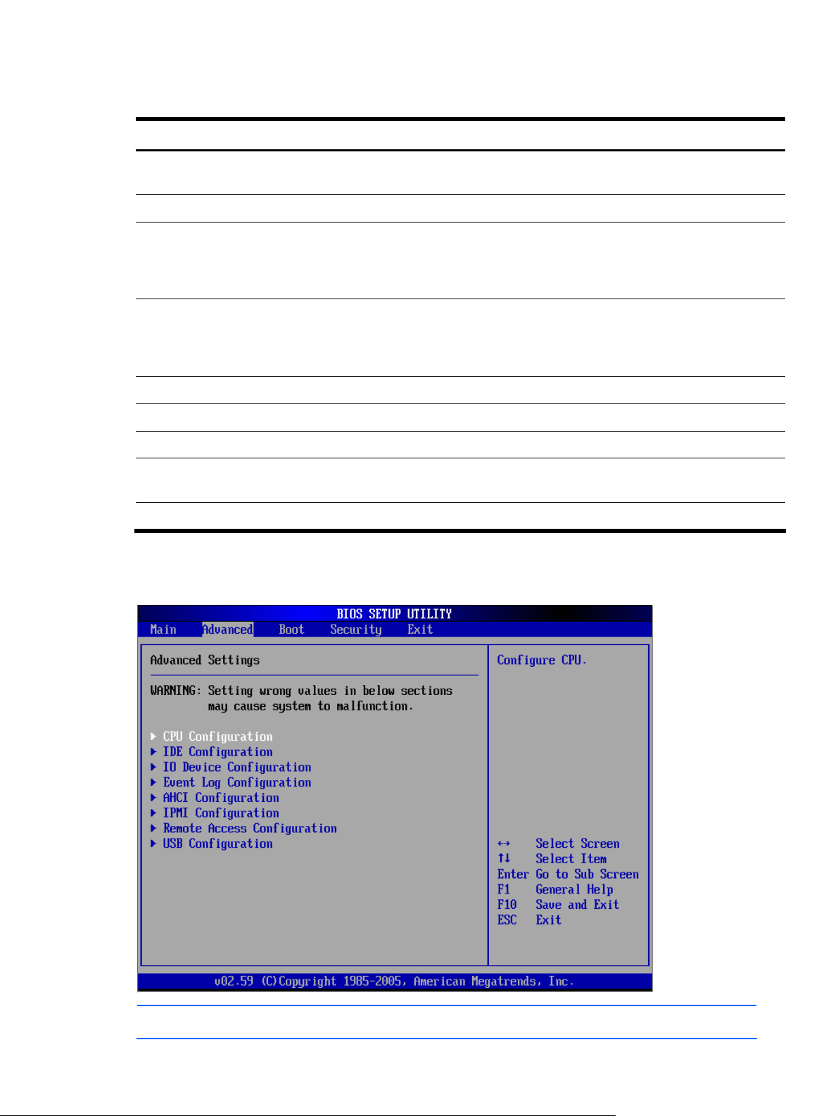
Table 3 Boot Settings Configuration submenu fields
Field Description Options
Summary Screen Set this value to not allow display hardware summary screen before booting the
Set this value to allow display s hardware summary screen before booting the OS Enabled
Boot up NumLock
This option does not enable the keyboard Number Lock automatically. To use the
POST F1 Prompt Set this value to allow wait up to 15 seconds for press F1. Delayed
Set this value to allow wait indefinitely for press F1. Enabled
Set this value to do not wait for F1; continue booting. Disabled
Restore on AC
Power Loss
Set this value to restore previous power state before loss occurred. Last State
Advanced menu
Figure 5 Advanced menu
Disabled
OS.
Set this value to allow the Number Lock on the keyboard to be enabled
automatically when the computer system is boot up. This allows the immediate use
of 10-keys numeric keypad located on the right side of the keyboard. To confirm
this, the Number Lock LED light on the keyboard will be lit.
10-keys on the keyboard, press the Number Lock key located on the upper lefthand corner of the 10-key pad. The Number Lock LED on the keyboard will light
up when the Number Lock is engaged. This is the default setting
Set this value to keep power off until the power button is pressed. Stay Off
Enabled
Disabled
NOTE: The CPU Configuration setup screen varies depending on the installed processor.
Contents 10
Page 11

Table 4 Advanced Settings
Field Description
CPU Configuration Use this screen to select options for the CPU Configuration Settings. Use the up and down
<Arrow> keys to select an item. Use the <Plus> and <Minus> keys to change the value of the
selected option. A description of the selected item appears on the right side of the screen. The
settings are described on the following pages.
IDE Configuration Use this screen to select options for the IDE Configuration Settings. Use the up And down
<Arrow> keys to select an item. Use the <Plus> and <Minus> keys to change the value of the
selected option. A description of the selected item appears on the right side of the screen. The
settings are described on the following pages. An example of the HDD Configuration screen is
shown below.
IO Device
Configuration
Event Log
Configuration
AHCI
Configuration
IPMI Configuration Select this option and press <Enter> to access the sub menu to view the contents of IPMI. A
Remote Access
Configuration
USB Configuration Select and press <Enter> to reach sub menu for the USB controller and USB 2.0 controller.
Use this screen to select options for IO device configuration. Use the up and down <Arrow>
key to select an item. Use the <Plus> and <Minus> keys to change the value of the selected
option. The settings are described on the following pages. The screen is shown below.
From this configuration screen, press <Enter> to select the submenu for viewing the event log,
marking events as read, or clearing the event log. Use the up and down <Arrow> keys to
select an item. Use the <Plus>and <Minus> keys to change the value of the selected option.
The settings are described on the following pages.
Select AHCI Configuration and press <Enter> to access the submenu. You can use the submenu
to view the contents of AHCI. Use the up and down <Arrow> keys to select an item. Use the
<Plus> and <Minus>keys to change the value of the selected option.
delay may be noticed when selecting IPMI -- this is due to the time for retrieval of sensor data.
Use the up and down <Arrow> keys to select an item. Use the <Plus> and <Minus>keys to
change the value of the selected option.
Press Enter to access the related submenu. For details on the submenu options, see the “Remote
Access Configuration submenu”
Use up and down <Arrow> keys to select an item.use the <Plus>and <Minus> keys to change
the value of the selected option. The settings are described on the following pages.
Contents 11
Page 12
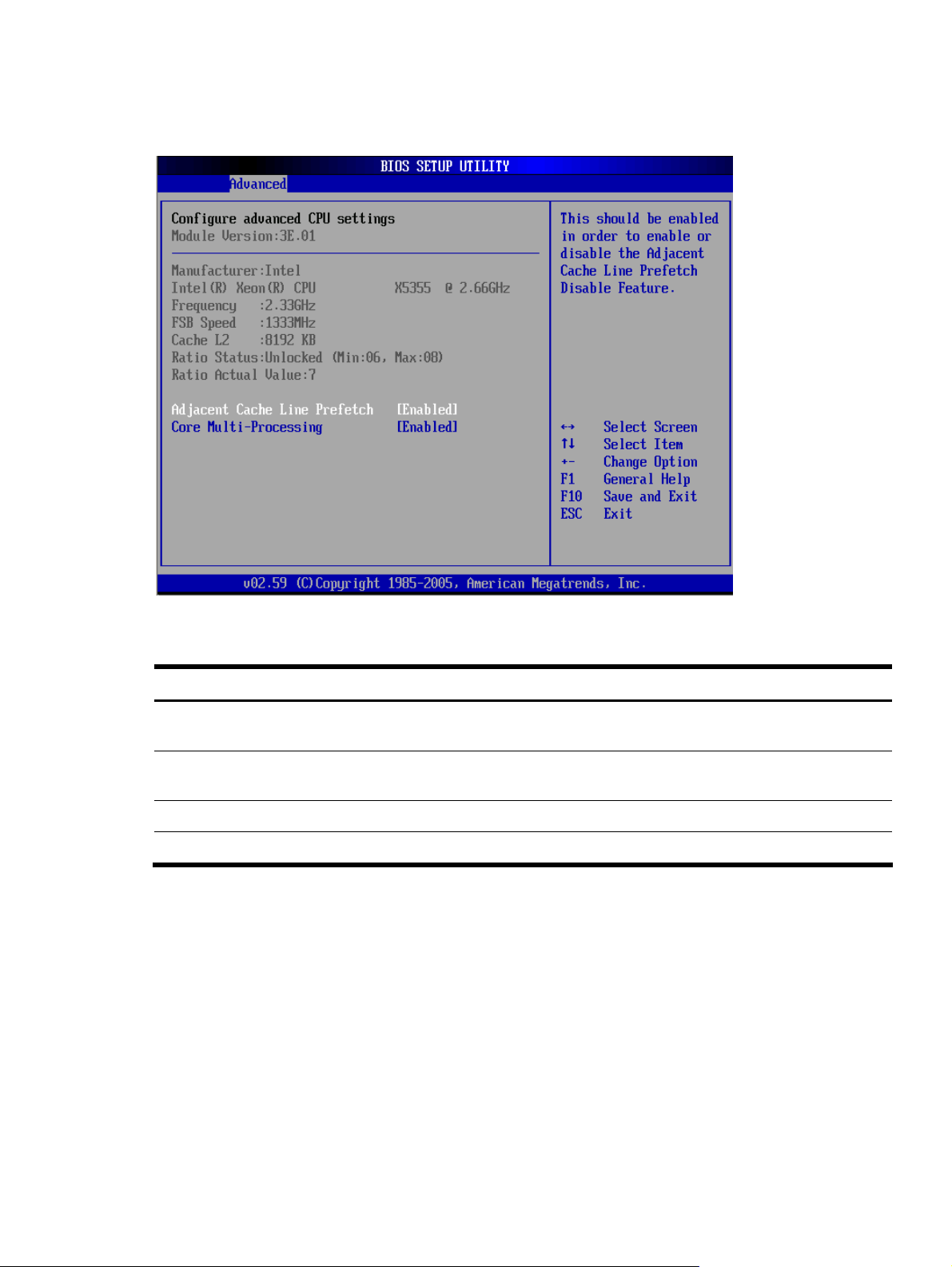
CPU Configuration submenu
Figure 6 CPU Configuration submenu
Table 5
Field Description Options
Adjacent Cache Line
Prefetch
Disabled the item. Not support adjacent cache line Prefetch debug
Core Multi-Processing Set this value only core0.logical processor 0 remains active. Enabled
Disabled this item will support multi-core processor. Disabled
CPU Configuration submenu fields
This should be enabled in order to enabled or disable the Adjacent Cache
Line Prefetch Disabled Feature. This is the default setting.
function.
Enabled
Disabled
Contents 12
Page 13
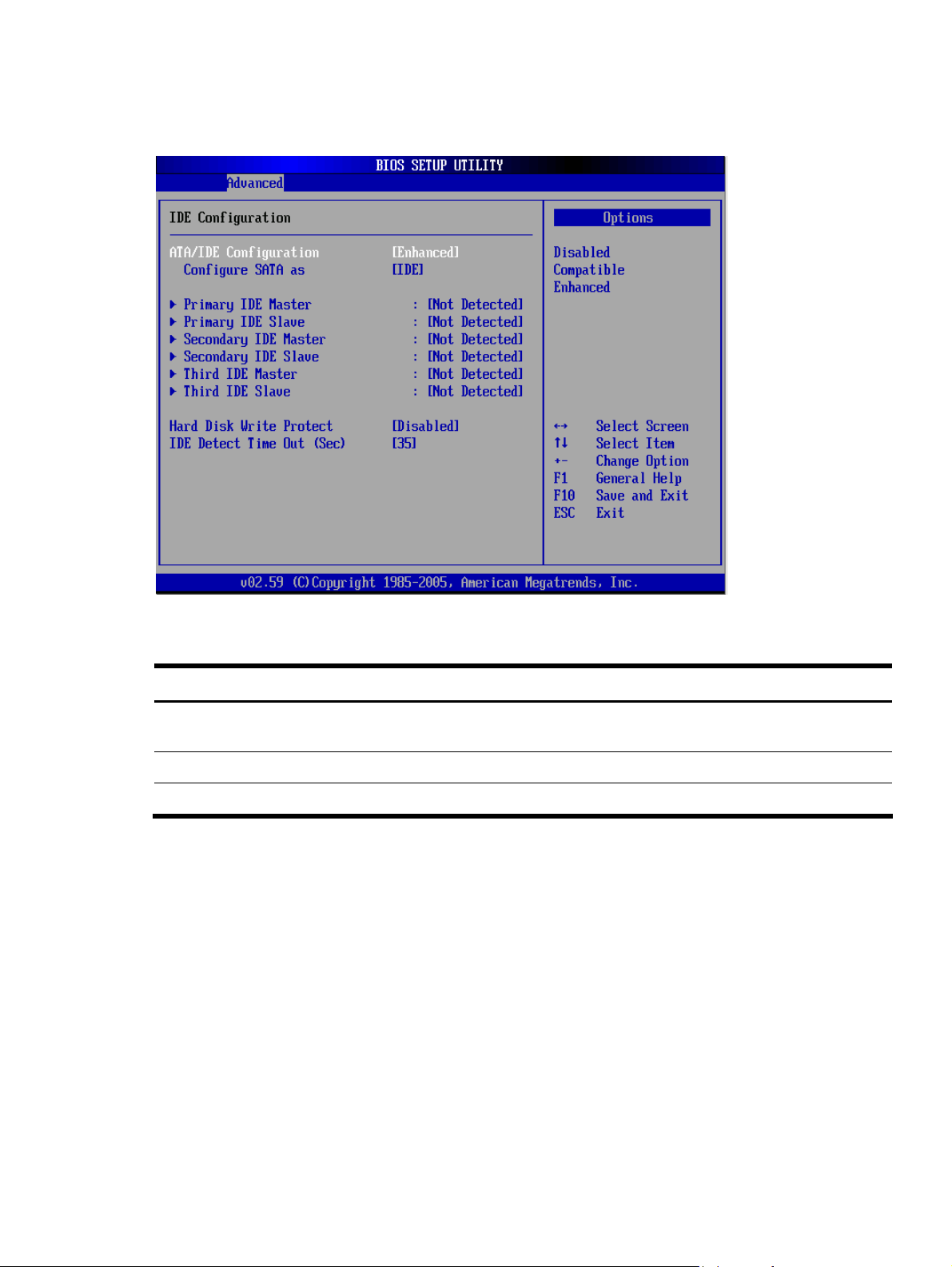
IDE Configuration submenu
Figure 7 IDE Configuration submenu
Table 6
IDE Configuration submenu fields
Field Description Options
ATA/IDE Configuration Set this value to prevent the computer system from using the integrated
IDE and SATA controller.
Set this mode to support compatible mode. Compatible
Set this mode to support enhanced mode. This is the default value. Enhanced
Disabled
Contents 13
Page 14
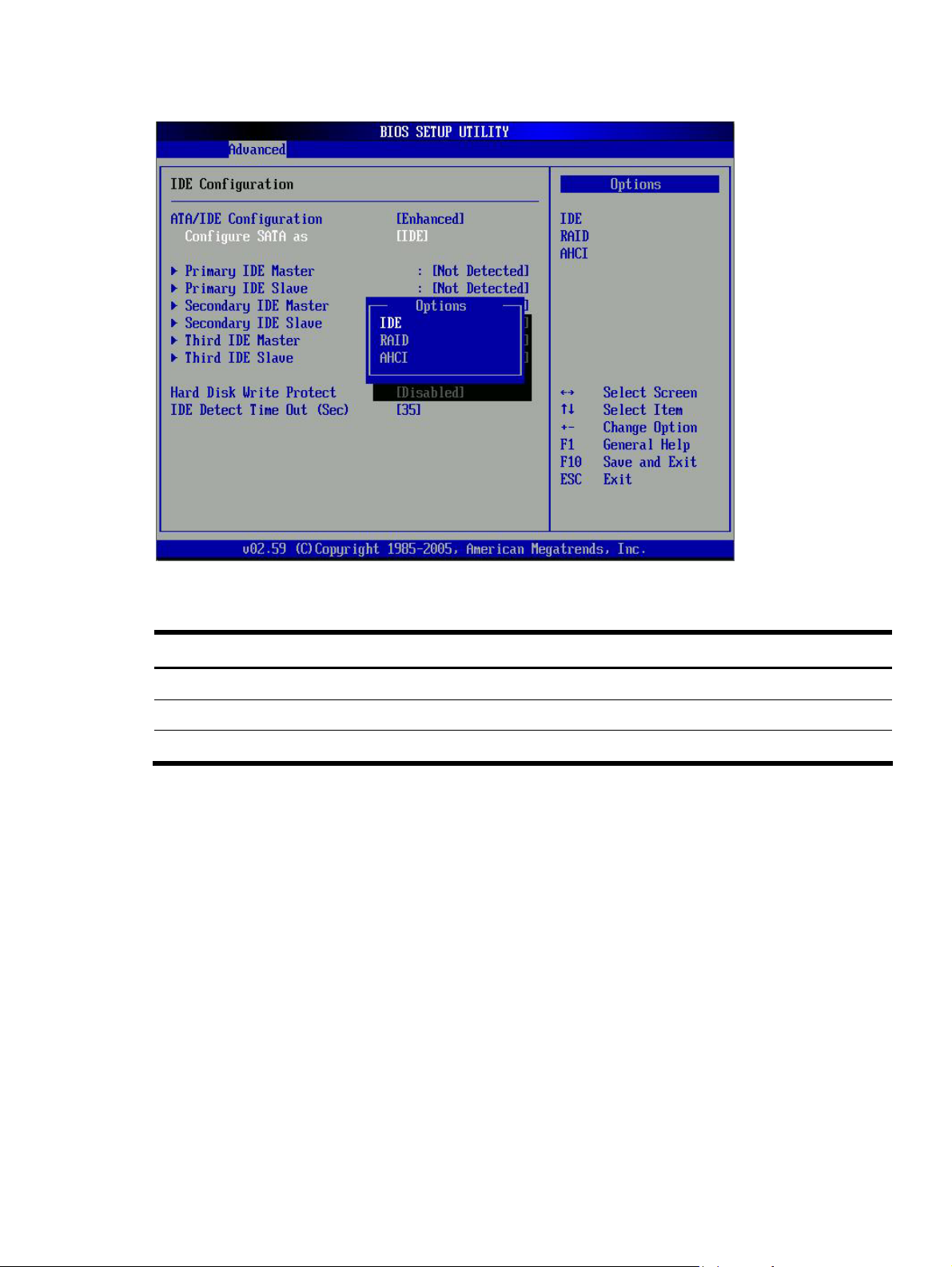
Figure 8 IDE Configuration submenu ---- Enhanced
Table 7
Configure SATA as submenu fields
Option Description
IDE Setting this value configures SATA in IDE mode. This is default value.
RAID Setting this value configures SATA in RAID mode.
AHCI Setting this value configures SATA in AHCI mode.
Contents 14
Page 15
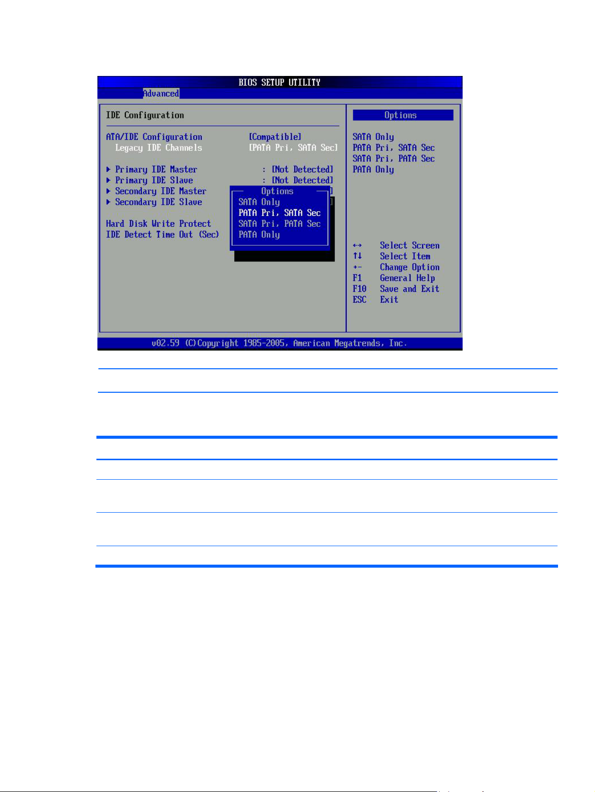
Figure 9 IDE Configuration submenu -- Compatible
NOTE: When setting Compatible mode, you can configure Legacy IDE Channels.
Table 8
Configure SATA as submenu fields
Option Description
SATA Only Set this value to only support SATA Device.
PATA Pri,SATA
Sec
SATA Pri,PATA
Sec
PATA Only Set this value to only support PATA Device.
Set this value to support PATA as primary device, select SATA as secondary Device.
Set this value to support SATA as primary device, select PATA as secondary Device.
Contents 15
Page 16
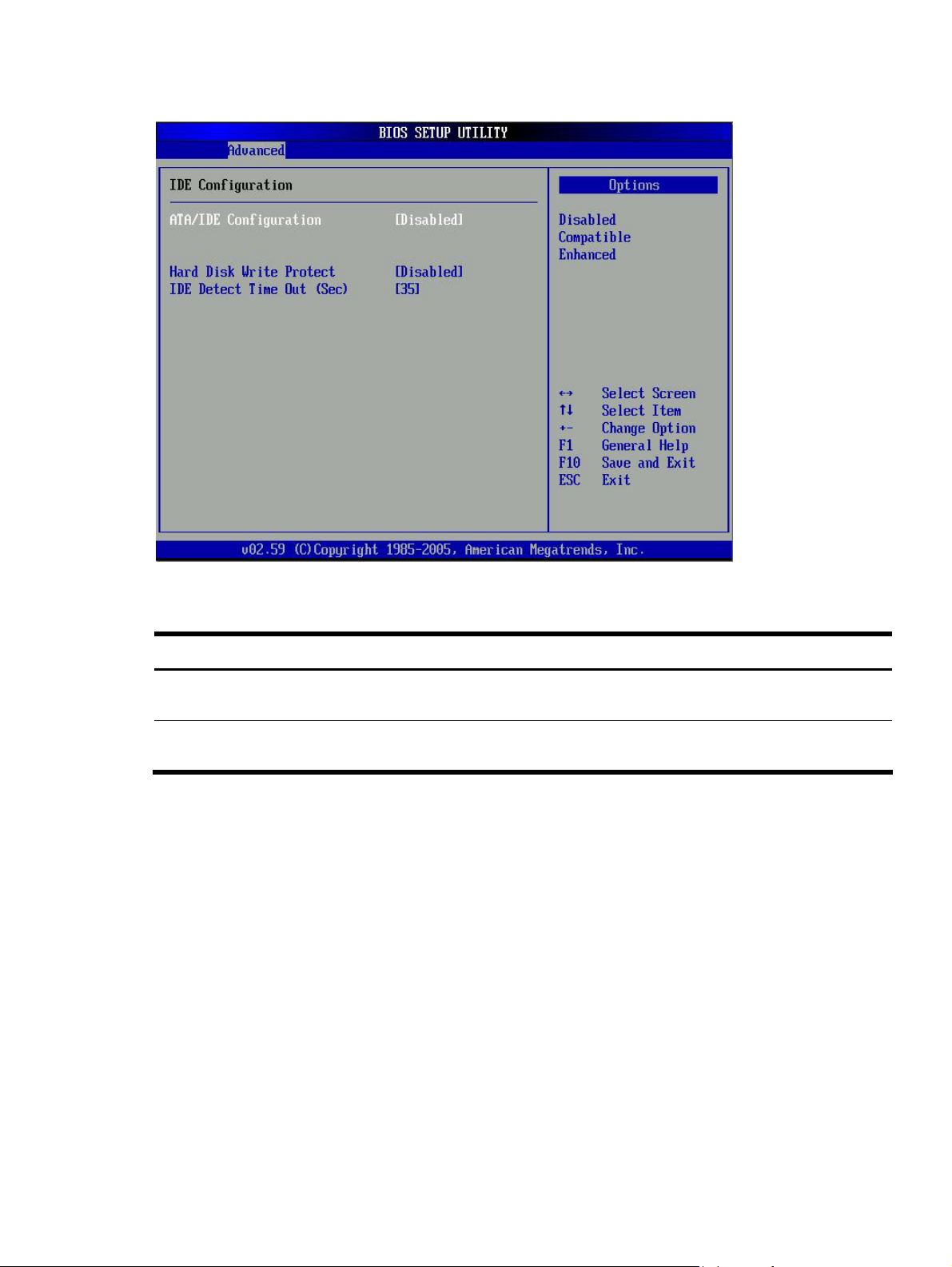
Figure 10 IDE Configuration submenu ---- Disabled
Table 9
Hard Disk Write Protect submenu fields
Option Description
Enabled This value enables hard disk write protection. This setting is only effective if device is accessed
through BIOS. This is the default setting.
Disabled This value disables hard disk write protection. This setting is only effective if device is accessed
through BIOS.
Contents 16
Page 17
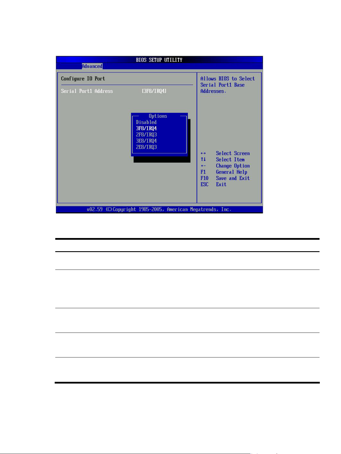
IO Device Configuration submenu
Figure 11 IO Device Configuration submenu
Table 10
IO Device Configuration submenu fields
Field Description Options
Serial Prot1
Address
Set this value to allow the serial port to use 3F8 as its I/O port address and IRQ 4
Set this value to allow the serial port to use 2F8 as its I/O port address and IRQ 3
Set this value to allow the serial port to use 3E8 as its I/O port address and IRQ 4
Set this value to allow the serial port to use 2E8 as its I/O port address and IRQ 3
Set this value to prevent the serial port from accessing any system resources.
When this option is set to Disabled, the serial port physically becomes unavailable
for the interrupt address. This is the default setting. The majority of serial port 1 or
COM1 ports on computer systems use IRQ4 and I/O Port 3F8 as the standard
setting. The most common serial device connected to this port is a mouse. If the
system will not use a serial device, it is best to set this port to Disabled.
for the interrupt address. If the system will not use a serial device, it is best to set
this port to Disabled.
for the interrupt address. If the system will not use a serial device, it is best to set
this port to Disabled.
for the interrupt address. If the system will not use a serial device, it is best to set
this port to Disabled.
Disabled
3F8/IRQ4
2F8/IRQ3
3E8/IRQ4
2E8/IRQ3
Contents 17
Page 18
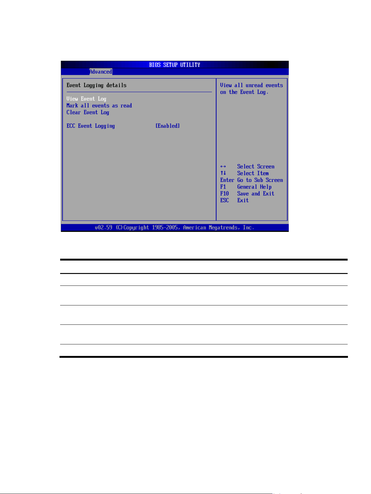
Event Log Configuration submenu
Figure 12 Event Log Configuration submenu
Table 11
Event Log Configuration submenu fields
Field Description Options
View Event Log This option displays the event log. The log displays system event information.
Mark all events
as read
Clear Event
Log
ECC Event
Logging
Set this value to prevent the BIOS from logging of ECC events Disabled
The option marks all events as read.
The option allows the user to clear the event log.
This setting allows logging of ECC events. This is the default setting Enabled
Contents 18
Page 19
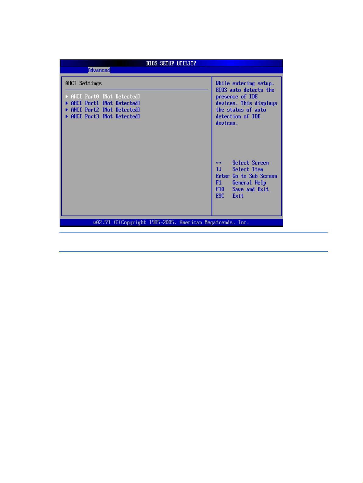
AHCI Configuration submenu
Figure 13 AHCI Configuration submenu
NOTE: While entering AHCI Port setup, BIOS auto detects the presence of devices. This displays the
status of auto detection of SATA Port devices, there are two statuses, hard disk and not detected.
Contents 19
Page 20
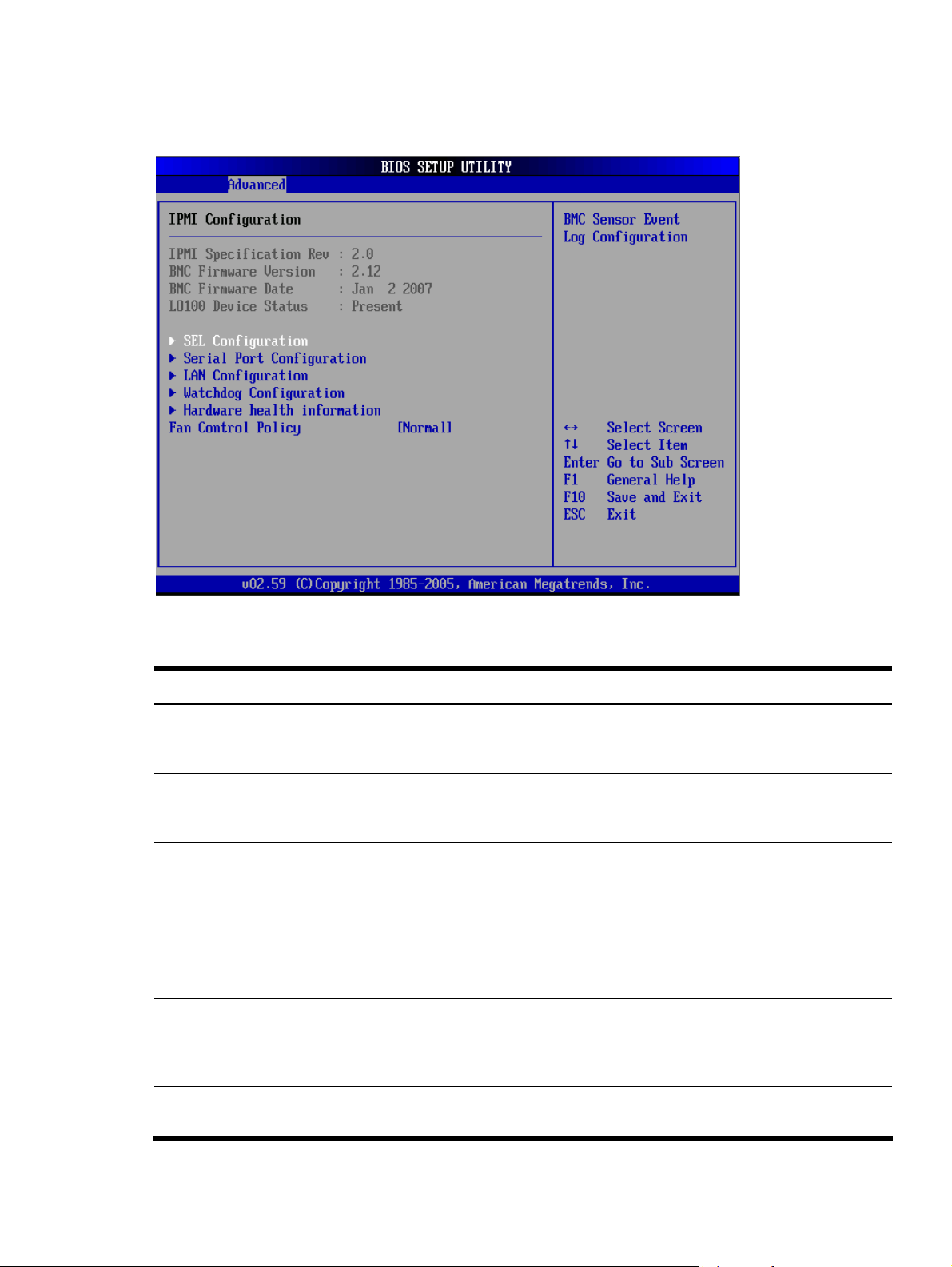
IPMI Configuration submenu
Figure 14 IPMI Configuration submenu
Table 12
IPMI Device Configuration submenu fields
Field Description
SEL Configuration Select SEL configuration in the left frame of the screen to go to the sub menu for that item.
Then you can press Enter to enter its sub-menu. You can display an about SEL Configuration
option by highlighting it using the<Arrow> keys.
Serial Port
Configuration
LAN Configuration Select set LAN configuration in the left frame of the screen to go to the sub menu for that item.
Watchdog
Configuration
Hardware health
information
Select serial port configuration in the left frame of the screen to go to the sub menu for that
item. Then you can press Enter to enter its sub-menu. You can display an about Serial Port
Configuration option by highlighting it using the<Arrow> keys.
You can display an about LAN option by highlighting it using the<Arrow> keys. Set LAN
Setup options are described in this section. The Set LAN BIOS Setup screen is shown below
(When you have a LO100 Device, this item will display).
Select watchdog configuration in the left frame of the screen and press<enter> to go to the
sub menu for that item. That will display POST Watchdog Timer Action, BMC Watch Dog
Time Out, you can change the default value.
Select Hardware health configuration in the left frame of the screen and press<enter> to go to
the sub menu for that item. That will display CPU temperature, ambient temperature, CPU fan
speed, system fan speed, chassis fan speed, these item can’t change by user, it accord with
the sense of the case.
Fan Control Policy Press Enter to access the related submenu. For details on the submenu options, see the “Fan
Control Policy submenu” section below.
Contents 20
Page 21
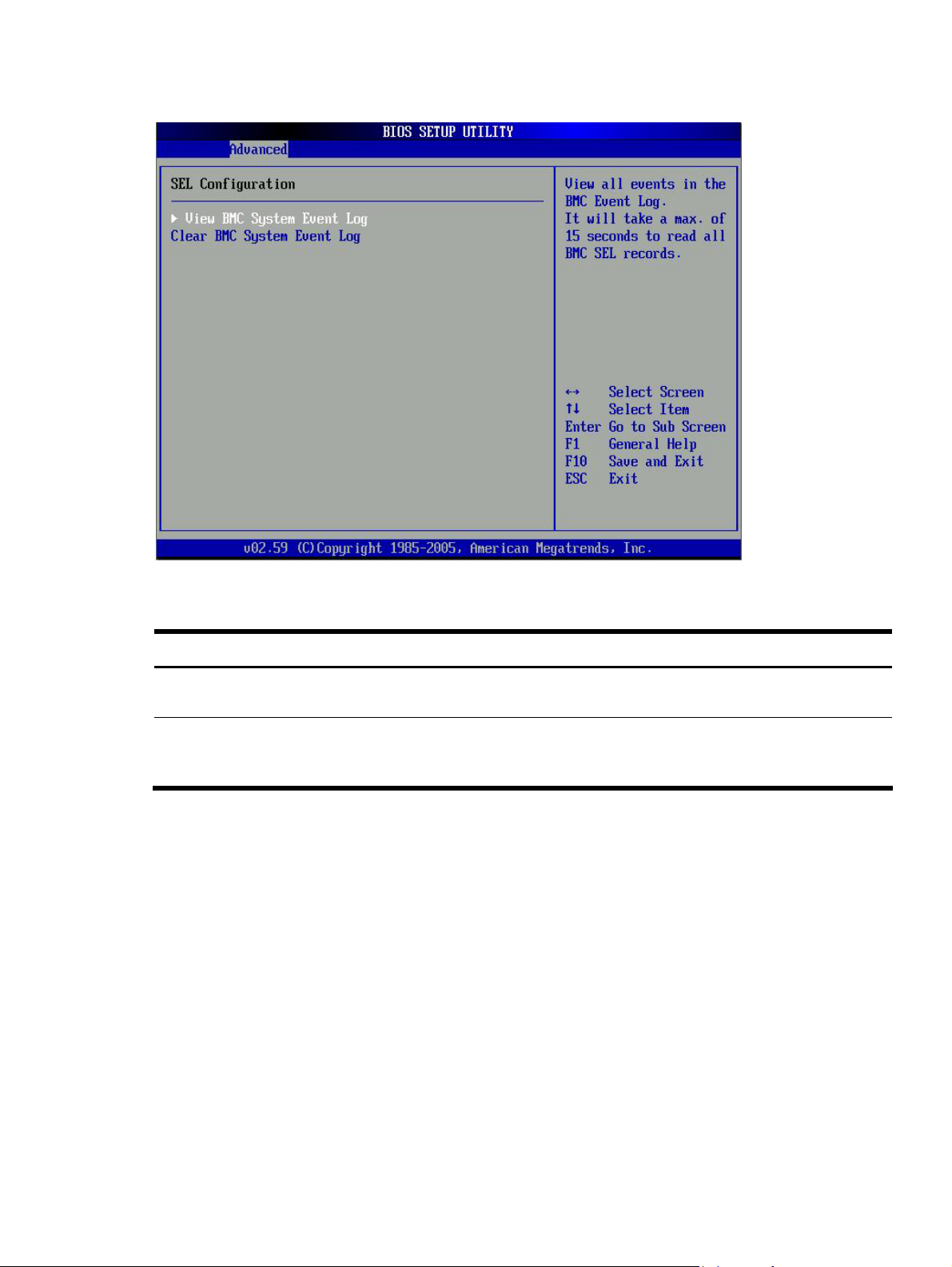
Figure 15 SEL Configuration submenu
Table 13
SEL Configuration submenu fields
Field Description
View BMC System
Event Log
Clear BMC System
Event Log
The option specifies BMC system event log. Select this option and press <Enter> to access
the sub menu you can view the contents of System Event log.
The option specifies clear system event log. If the BMC Event log is full, you can choose this
item to clear out the BMC Event log. If this option is selected, a confirmation prompt will
appear before the log is cleared.
Contents 21
Page 22
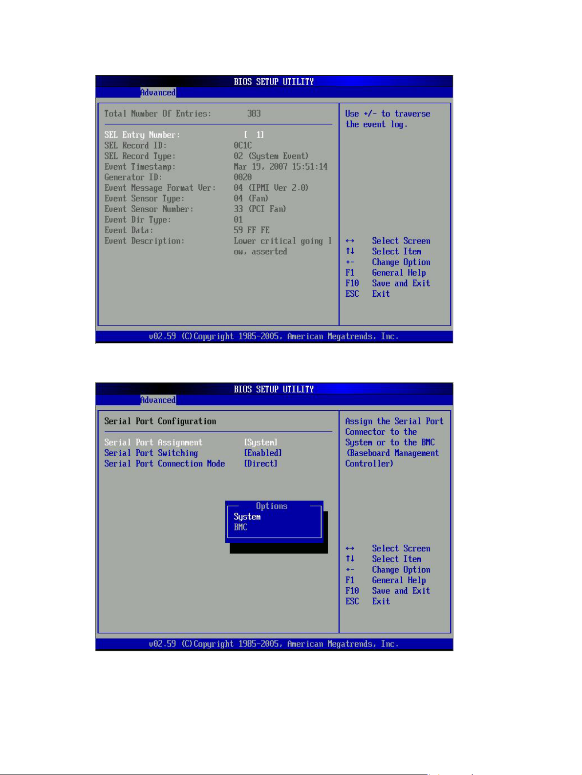
Figure 16 View BMC System Event Log submenu
Figure 17 Serial Port Configuration
Contents 22
Page 23
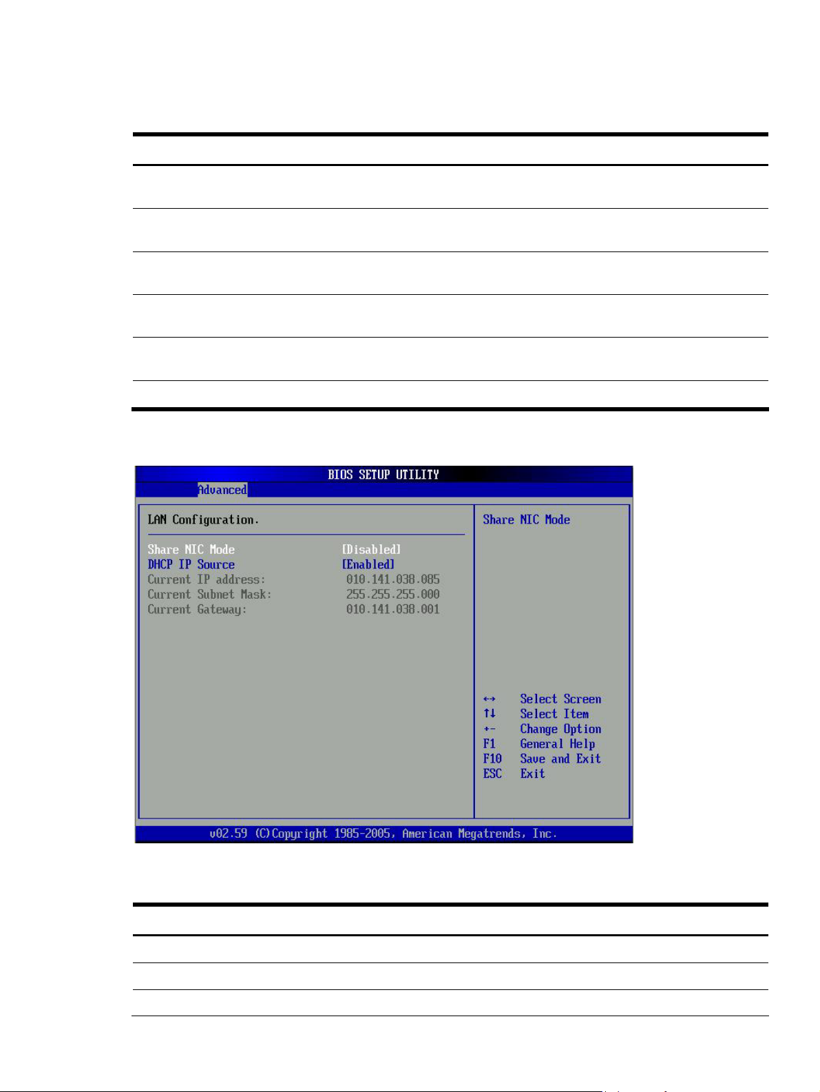
Table 14
Serial Port Configuration submenu fields
Field Description Options
Serial Port
Assignment
This setting will assign the serial port connector to the BMC (Baseboard
Serial Port Switching This setting allows the Serial port switch between system and BMC. This is the
This setting will prevent the Serial port from switching between system and
Serial Port
Connection Mode
Serial port connection mode is Modem Modem
This setting will assign the serial port connector to the system. This is the
default setting.
management controller
default setting
BMC.
Serial port connection mode is Direct. This is the default setting Direct
System
BMC
Enabled
Disabled
Figure 18 LAN Configuration submenu
Table 15 LAN Configuration submenu fields
Field Description Options
Share NIC Mode Setting this value will prevent support from share NIC mode Disabled
Setting this value will allow support share NIC mode.(Disabled the KVM). Enabled
DHCP IP Source Setting this value will allow dynamic IP assignment. Enabled
Contents 23
Page 24

Table 15 LAN Configuration submenu fields
Field Description Options
Setting this value will allow manual IP assignment. Disabled
Figure 19 Watchdog Configuration submenu
Table 16
Watchdog Configuration submenu fields
Field Description Options
POST Watchdog
Timer Action
Disabling this option disables any BMC action if OS crashes or hangs.
Set this value to allow BMC to power down if the operating system
Set this value to allow BMC to power cycle if the operating system
BMC Watch Dog
Time Out
Sets a 5 minute timeout value for BMC to wait before assuming the
Set this value to allow BMC to reset if the operating system crashes or
hangs.
This is the default setting.
crashes or hangs.
crashes or hangs.
Sets a10 minute timeout valuefor BMC to wait before assuming the
system has crashed and needs to reset. This is default value.
system has crashed and needs to reset.
This is the default setting.
Reset System
Disabled
Power Down
Power Cycle
10 Min
5 Min
Contents 24
Page 25

Table 16 Watchdog Configuration submenu fields
Field Description Options
Sets a 15 minute timeout valuefor BMC to wait before assuming the
system has crashed and needs to reset.
Sets a 20 minute timeout value for BMC to wait before assuming the
system has crashed and needs to reset.
Sets a 25 minute timeout valuefor BMC to wait before assuming the
system has crashed and needs to reset.
Sets a 30 minute timeout value for BMC to wait before assuming the
system has crashed and needs to reset.
Figure 20 Hardward health information submenu
15 Min
20 Min
25 Min
30 Min
Contents 25
Page 26

Figure 21 Fan Control Policy submenu
Remote Access Configuration submenu
Figure 22 Remote Access Configuration submenu
Contents 26
Page 27

Table 17
Remote Access Configuration submenu fields
Field Description Options
Remote Access
EMS support(SPCR) Setting this value to prevent the BIOS from using EMS Support (SPCR)
Setting this value to support the BIOS from using EMS Support (SPCR) Enabled
Configure remote access type and parameters Disabled
function
USB Configuration submenu
Figure 23 USB Configuration submenu
Disabled
Table 18 USB Configuration submenu fields
Field Description Options
USB Controller
This setting makes the onboard USB function unavailable. Disabled
USB 2.0 Controller This setting allows the use of USB ports transfer data in 480Mbps. This is
This setting allows the use of USB ports transfer data in 12Mbps. Disabled
This setting allows the use of the USB function. This is the default setting. Enabled
Enabled
the default setting
Contents 27
Page 28

Table 18 USB Configuration submenu fields
Field Description Options
BIOS EHCI HandOff
Set this value not allow support the EHCI-off. Disabled
Boot Menu
Figure 24 Boot Menu
Set this value can support the EHCI-off, this is default value. Enabled
Table 19
Boot Menu
Field Description
Boot Device Priority Use this screen to specify the order in which the system checks for the device to boot from.
To access this screen, select Boot Device priority on the Boot setup screen and press
<Enter>, the following screen display
Hard Disk Drives Use this screen to view the hard disk drives in the system. To access this screen, select Hard
disk drives on the Boot Setup screen and press <Enter>. Then you can select It as the first
boot device or disabled it as the 1st Drive.
Removable Drives Use this screen to removable drives in the system. To access this screen, select removable
drives on the Boot Setup screen and press <Enter>. Then you can select It as the first boot
device or disabled it as the 1st Drive.
CD/DVD Drives Use this screen to view the CD/DVD Drives in the system. To access this screen, select
CD/DVD drives on the Boot Setup screen and press <Enter>. Then you can select
It as the first boot device or disabled it as the 1st Drive.
Contents 28
Page 29

Table 19 Boot Menu
Field Description
Network Drives Use this screen to network drives in the system. To access this screen, select network drives
on the Boot Setup screen and press <Enter>. Then you can select It as the first boot device
or disabled it as the 1st Drive.
Embedded NIC PXE The option specifies the embedded NIC PXE. The defaults is enabled
Figure 25 Boot Device Priority submenu
NOTE: Set the boot device options to determine the sequence in which the Server checks which
device to boot from. The default setting are “CDROM”,USB Floppy or Disk-on-key as A :”,”USB
Disk-on-key as C:”,”A:”,”C:”,”NIC:”.
Contents 29
Page 30

Figure 26 Hard Disk Drives submenu
Table 20
Hard Disk Drives fields
Option Description
HDD Select this device as the 1st Drive.
Disabled Disabled the hard disk as the first boot device.
Contents 30
Page 31

Figure 27 Removable Drives submenu
Table 21 Removable drives
Option Description
Removable Select this device as the 1st Drive.
Disabled Disabled the removable as the first boot device.
Contents 31
Page 32

Figure 28 CD/DVD Drives submenu
Table 22
CD/DVD drives
Option Description
CD/DVD Select this device as the 1st Drive.
Disabled Disabled the CD/DVD Drives as the first boot device.
Contents 32
Page 33

Figure 29 Network Drives submenu
Table 23 Network Drives fields
Option Description
Embedded NIC Select this device as the 1st Drive.
Disabled Disabled the network drive as the first boot device.
Contents 33
Page 34

Security menu
The Security menu allows users to set an administrator password. When entered, this password allows
the user to access and change all settings in the Setup Utility.
Figure 30 Security menu
To set an administrator password:
1. Indicates whether a supervisor password has been set, If the password has been installed,
Installed displays, if not, not installed displays.
In the Security menu screen, in the Change Administrator Password field, press Enter.
The Enter New Password window displays.
Contents 34
Page 35

Figure 31 Enter New Password
2. Type a new password in the Enter New Password box. The password may consist of up to eight
alphanumeric characters (A-Z, a-z, 0-9), then press Enter , The Confirm New Password window
displays.
Figure 32 Confirm new password
3. Type the same password in the Confirm New Password box to verify the first entry, then press
Enter. The Password Installed OK windows displays, press OK finish the password installed.
Contents 35
Page 36

Figure 33 Password installed
4. Press F10 to save the password and close the Setup Utility.
Setup automatically changes the administrator Password Is field to set.
To change the administrator password:
1. In the Security menu screen, in the Change Administrator Password field, press Enter. The Enter
New Password window displays. Type a new password in the Enter New Password box.
Figure 34 Enter New Password submenu
Contents 36
Page 37

2.
Type the same password in the Confirm New Password box to verify the first entry, then press
Enter, The Password Installed OK windows display, press Enter to finish
Figure 35 Confirm New Password submenu
Figure 36 Password installed
To clear the administrator password:
Contents 37
Page 38

1.
In the Security menu screen, in the Clear Administrator Password field, press Enter. The Clear
Administrator Password window displays. The OK is to clear the administrator password, the
cancel is to discard the password.
Figure 37 Clear Administrator Password submenu
2. In the Security menu screen, in Password Check [setup] field, press Enter. The Setup is to check
password while invoking setup, the Always is to check password while invoking setup a well as
on each boot.
Figure 38 Password Check submenu
Contents 38
Page 39

Table 24
Option Description
Setup Set this value need to check password while invoking the set up utility.
Always Set this value must check password while invoking setup on each boot.
3. Press F10 to save the changes you made and close the Setup Utility.
Exit menu
The Exit menu displays several options on how to quit the Setup Utility. Select any of the exit options
then press Enter.
Figure 39 Exit menu
Password Check fields
Table 25
Exit menu options
Option Description
Save Changes and Exit Save the changes made and exit the Setup Utility
Discard Changes and
Exit
Discard Changes Discard the changes in the utility
Load Option Default Loads the default settings for all BIOS setup fields.
Discard the changes and exit the setup utility
The boot-time diagnostic screen displays basic and important information about the current server
configuration and is necessary for troubleshooting and may be required when asking for technical
support. This information includes:
• Processor specifications
Contents 39
Page 40

• BIOS version and release date
• BMC firmware version
• Size of the system and video memory, as well as the memory size allotted for the cache RAM
and option ROM
• Serial port base I/O address
• Available hard drives and expansion boards
• Server asset tag and serial number
• MAC address of each of the three LAN ports
It is recommended that you check this screen during the initial system setup and each time you install,
remove, or upgrade accessories.
You first need to enable the display of the diagnostic screen during bootup. Follow the steps below.
Boot-time diagnostic screen
To view the boot-time diagnostic screen
1. In the Main menu screen, select Boot Options.
2. Select the Boot Summary Screen field.
3. Press the plus (+) or minus (-) key to set the field to Enabled.
4. Press F10 to save the changes you made and close the Setup Utility.
5. Reboot the server.
The diagnostic screen is displayed briefly at the end of POST.
Figure 40 Boot-time diagnostic screen
6. Press the Pause/Break key to continue displaying the screen until another key is pressed.
7. Press any key to continue with the system bootup.
Contents 40
Page 41

Recording custom Setup values
Write down the settings from the Setup Utility and keep them in a safe place. If the custom values ever
need restoring (after clearing CMOS, for example), you must run the Setup Utility and enter these
custom settings again. Having a record of these custom settings makes this much easier.
Loading system defaults
If the system fails after you make changes in the Setup menus, reboot the server, enter Setup, and
load the system default settings to correct the error. These default settings have been selected to
optimize the server’s performance. Setup default settings are quite demanding in terms of resource
consumption. If you are using low-speed memory chips or other types of low-performance components
and you choose to load these settings, the system might not function properly.
To load the system defaults:
1. Reboot the server in a normal manner.
2. During POST, press F10 to access the Setup Utility.
3. Press F9 to load the default values.
4. Press F10 to save the changes and close the Setup Utility.
Clearing CMOS
You may need to clear the Setup configuration values (CMOS) if the configuration has been
corrupted, or if incorrect settings made in the Setup Utility have caused error messages to be
unreadable. Clearing the CMOS data removes the administrator password.
The clear CMOS setting is on clear CMOS button(SW2) on the system board. Refer to the HP ProLiant
DL180 Server Maintenance and Service Guide for the location of this jumper block and the clear
CMOS setting.
To clear CMOS:
1. Perform the pre-installation procedures described on page 72.
2. If necessary, remove any expansion boards, assemblies, or cables that prevent access to the
press CMOS button(SW2).
3. Locate the clear CMOS button(SW2) on the system board.
4. Press clear CMOS button(SW2) to clear the CMOS memory.
5. Perform the post-installation procedures as described on page 73.
6. During POST, press F10 to access the Setup Utility.
7. Press F9 to load the system default values.
8. Press F10 to save the changes you made and
Power-On Self Test (POST).
When the server boots up, a series of tests are displayed on the screen. This is referred to as PowerOn Self-Test (POST). POST is a series of diagnostic tests that checks firmware and assemblies to
ensure that the server is properly functioning. This diagnostic function automatically runs each time the
server is powered on.
Contents 41
Page 42

These diagnostics, which reside in the BIOS ROM, isolate server-related logic failures and indicate the
board or component that needs to be replaced, as indicated by the error messages. Most server
hardware failures are accurately isolated during POST. The number of tests displayed depends on the
configuration of the server.
POST error indicators
When POST detects a system failure, it either:
• Displays a POST error message
• Emits a series of beep codes (requires an optional expansion board
Recoverable POST Errors
Whenever a non-fatal error occurs during POST, an error message describing the problem appears
onscreen. These text messages are displayed in normal video (white text on black background). It
shows the details of the error. The following is an example of a POST error message:
Error message 1 of 1: Error code 0103
Keyboard not detected - Keyboard error
In some cases an error message may include recommendations for troubleshooting or require that you
press the Enter key to display recommendations. Follow the instructions on the screen.
Table 26 lists the most common POST error messages with their corresponding troubleshooting
recommendation.
It is recommended that you correct the error before proceeding, even if the server appears to boot
successfully. If your system displays one of the messages marked below with an asterisk (*), write
down the code and message and contact your HP Customer Support provider.
When no POST error messageis displayed but the server stops during POST, listen for beep codes.
Table 26
POST Error Messages
Error code Error message Description/corrective action
0200 Failure Fixed Disk Fixed disk is not working or not configured properly.
Run Setup and check if the fixed-disk type is correctly identified.
Check to see if fixed disk is attached properly.
0210 Stuck key Stuck key on keyboard.
1
Locate the stuck key on your keyboard and release it.
2 Reboot the server.
0211 Keyboard error Keyboard not working.
Verify that the keyboard cable is securely connected to the keyboard
port (not the mouse port) on the rear panel of the server.
If the problem persists, replace the keyboard or contact your HP
Customer Support provider.
0212 Keyboard Controller
Failed
0220 Monitor type does not
match CMOS - Run SETUP
Keyboard controller failed test.
The attached monitor cannot be correctly identified by Setup.
Run Setup and check if the monitor type is correctly identified.
Contents 42
Page 43

Table 26 POST Error Messages
Error code Error message Description/corrective action
0250 System battery is dead -
Replace and run SETUP
0251 System CMOS checksum
bad - Default
configuration used
The CMOS clock battery indicator shows the system battery is dead.
1 Replace the system battery following the procedures in the HP ProLiant
DL180 Server Maintenance and Service Guide.
2 Run Setup to reconfigure the system.
The settings in the Setup Utility have been corrupted or modified
incorrectly, perhaps by an application program that changes data
stored in CMOS. You can either:
• Load the system default values following the procedures on page
40.
• Access Setup and enter your own custom values.
If the error persists, check the system battery or contact your HP
Customer Support provider.
0260 System timer error The timer test failed. Requires repair of the system board.
0270 Real time clock error Real-Time Clock (RTC) fails BIOS hardware test. May require board
repair.
0271 Check date and time
settings
0280 Previous boot incomplete
– Default configuration
used
BIOS found date or time out of range and reset the RTC. May require
setting legal date (1991-2099). Access Setup and check the values in
the System Timeand System Datefields of the Main menu.
Initial bootup failed. BIOS automatically loads the default system values,
then boot again.
0281 Memory size found by
POST differed from
CMOS
02F5 DMA test failed The DMA control test failed.
02F6 Software NMI failed An NMI signal is detected and/or a user has pressed the NMI switch.
POST beep codes
There are several POST routines that issue a POST terminal error and shut down the system if they fail.
Before shutting down the system, the terminal-error handler issues a beep code signifying the test
point error, writes the error to port 80h, attempts to initialize the video, and writes the error in the
upper left corner of the screen (using both mono and color adapters).
NOTE: An optional POST code expansion board must be installed in the server for the POST beep
codes to be audible.
The POST routines cannot display messages when an error occurs if any of the following are present:
• The error occurs before the video display is initialized.
• The video configuration fails, either there’s no graphics card installed or the one installed is
faulty.
• An external ROM module does not properly checksum to zero.
• The system memory cannot be initialized.
The user has added or removed a memory module, thus a memory size
that is different from the previous bootup.
Contents 43
Page 44

If an optional POST code expansion board is installed in the server, during these instances, the server
emits a buzzing sound followed by a series of audible beeps. An external ROM module can also
issue audible errors, usually consisting of one long tone followed by a series of short tones. If you get
a blank screen on boot but hear beeps, count the beeps and refer to Table 18 for their corresponding
meaning. If you miss the beep code:
1. Turn off the server by pressing the power button for five seconds or more.
2. Restart the server by pressing the power button.
3. Listen for the signal again.
The routine derives the beep code from the test point error as follows:
1. The 8-bit error code is broken down to four 2-bit groups (Discard the most significant group if it
is 00).
2. Each group is made one-based (1 through 4) by adding 1.
3. Short beeps are generated for the number in each group.
Example:
Test point 01Ah = 00 01 10 10 = 1-2-3-3 beeps
Table 27 lists the checkpoint codes written at the start of each test and the beep codes issued for
terminal errors.
Table 27
Checkpoint codes
01h Initialize IPMI
02h Verify real mode
03h Disable non-maskable interrupts
04h Get processor type
06h Initialize system hardware
07h Disable shadow and execute code from the ROM
08h Initialize chipset with initial POST values
09h Set IN POST flag
0Ah Initialize processor registers
0Bh Enable processor cache
0Ch Initialize caches to initial POST values
0Eh Initialize I/O component
0Fh Initialize the local bus IDE
10h Initialize power management
11h Load alternate registers with initial POST values
12h Restore processor control word during warm boot
13h Initialize PCI bus mastering devices
14h Initialize keyboard controller
Contents 44
Page 45

Table 27 Checkpoint codes
16h BIOS ROM checksum
17h Initialize cache before memory auto size
18h 8254 timer initialization
1Ah 8237 DMA controller initialization
1Ch Reset programmable interrupt controller
20h 1-3-1-1 Test DRAM refresh
22h 1-3-1-3 Test 8742 keyboard controller
24h Set ES segment register to 4 GB
26h Enable gate A20 line
28h Autosize DRAM
29h Initialize POST memory manager
2Ah Clear 512 KB base RAM
2Bh Initialize extended CMOS
2Ch 1-3-4-1 RAM failure on address line xxxx
2Eh 1-3-4-3 RAM failure on data bits xxxx of low byte of memory bus
2Fh Enable cache before system BIOS shadow
30h RAM failure on data bits xxxx of high byte of memory bus
32h Test processor bus-clock frequency
33h Initialize AMI Dispatch Manager
34h Test CMOS
35h Reinitialize registers
36h Warm start shut down
37h Reinitialize chipset with initial POST values
38h Shadow system BIOS ROM
39h Reinitialize caches to initial POST values
3Ah Auto size cache
3Ch Advanced configuration of chipset registers
3Dh Load alternate registers with CMOS values
41h Initialize extended memory for ROM pilot
42h Initialize interrupt vectors
45h POST device initialization
46h 2-1-2-3 Check ROM copyright notice
Contents 45
Page 46

Table 27 Checkpoint codes
48h Check video configuration against CMOS
49h Initialize PCI bus and devices
4Ah Initialize all video adapters in system
4Bh Quiet boot start (optional)
4Ch Shadow video BIOS ROM
4Eh Display BIOS copyright notice
4Fh Initialize multi-boot
50h Display processor type and speed
51h Initialize EISA board
52h Test keyboard
54h Set key click if enabled
55h Enable USB devices
56h Enable keyboard
57h Enable FireWire devices
58h 2-2-3-1 Test for unexpected interrupts
59h Initialize POST display service
5Ah Display prompt ”Press F10 to enter SETUP”
5Bh Disable processor cache
5Ch Test RAM between 512 and 640 KB
5Eh Test base memory
60h Test extended memory
62h Test extended memory address lines
64h Jump to user patch 1
66h Configure advanced cache registers
67h Initialize multiprocessor APIC
68h Enable external and processor caches
69h Setup System Management Mode (SMM) area
6Ah Display external L2 cache size
6Bh Load custom defaults (optional)
6Ch Display shadow-area message
70h Display error messages
72h Check for configuration errors
Contents 46
Page 47

Table 27 Checkpoint codes
74h Test real-time clock
76h Check for keyboard errors
7Ah Check for key lock errors
7Ch Set up hardware interrupt vectors
7Dh Initialize Intelligent System Monitoring
7Eh Initialize coprocessor if present
80h Disable onboard super I/O ports and IRQs
81h Late POST device initialization
82h Detect and install external RS232 ports
83h Configure non-MCD IDE controllers
84h Detect and install external parallel ports
85h Initialize PCI devices
86h Re-initialize onboard I/O ports
87h Configure system board configurable devices (optional)
88h Initialize BIOS data area
89h Enable non-maskable interrupts
8Ah Initialize extended BIOS data area
8Bh Test and initialize PS/2 mouse
8Ch Initialize floppy controller
8Eh Autotype hard drive size
8Fh Determine number of ATA drives (optional)
90h Initialize hard disk controllers
91h Initialize local bus hard disk controllers
92h Jump to user patch 2
93h Build MP table for multiprocessor boards
95h Install CD-ROM for boot
96h Clear huge ES segment register
97h Fix up MP table
98h 1-2 Search for option ROMs. One long, two short beeps on checksum failure
99h Check for SMART drive (optional)
9Ah Shadow option ROMs
9Bh Power management processor speed
Contents 47
Page 48

Table 27 Checkpoint codes
9Ch Set up power management
9Dh Initialize security engine (optional)
9Eh Enable hardware interrupts
9Fh Determine number of SATA or SAS drives
A0h Set time of day
A2h Check key lock
A4h Initialize typematic rate
A8h Erase F10 prompt
AAh Scan for F10 key stroke
ACh Enter Setup
AEh Clear boot flag
B0h Check for errors
B1h Inform ROM pilot about the end of POST
B2h POST done, prepare to boot operating system
B3h Store extended CMOS
B4h 1 One short beep before boot
B5h Terminate quiet boot (optional)
B6h Check password (optional)
B7h Initialize ACPI BIOS
B9h Prepare boot
BAh Initialize SMBIOS
BBh Initialize PnP option ROMs
BCh Clear parity checkers
BDh Display Multi-boot menu
BEh Clear screen (optional)
BFh Check virus and backup reminders
C0h Try to boot with INT 19
C1h Initialize POST Error Manager (PEM)
C2h Initialize error logging
C3h Initialize error display function
C4h Initialize system error handler
C5h PnP and dual CMOS (optional)
Contents 48
Page 49

Table 27 Checkpoint codes
C6h Initialize note dock (optional)
C7h Initialize note dock late
C8h Force check (optional)
C9h Extended checksum (optional)
CAh Redirect Int 15h to enable remote keyboard
CBh Redirect Int 13h to memory technologies devices such as ROM, RAM, PCMCIA,
and serial disk
CCh Redirect Int 10h to enable remote serial video
CDh Re-map I/O and memory for PCMCIA
CEh Initialize digitizer and display message
POST-related troubleshooting
Perform the following procedures when POST fails to run, error messages are displayed, or beep
codes are emitted.
If the POST failure is during a routine bootup, verify the following conditions:
• All external cables and power cables are firmly plugged in.
• The power outlet to which the server is connected is working.
• The server and monitor are both turned on. The bicolor power status LED indicator on the front
panel must be green.
• The monitor's contrast and brightness settings are correct.
• All internal cables are properly connected and all boards firmly seated.
• The processor is fully seated in its socket on the system board.
• The heat sink is properly installed on top of the processor.
• All memory modules are properly installed.
If the POST failure occurs after installing an accessory, perform the following steps:
1. Perform the pre-installation procedure described on page 73.
2. If necessary, remove any expansion boards, assemblies, or cables that prevent access to the
system components.
3. Check the following conditions:
a. If you have installed an expansion board, verify that the board is firmly seated in its slot and
any switches or jumpers on the board are properly set. Refer to the documentation provided
with the expansion board.
b. All internal cabling and connections are in their proper order.
c. If you have changed any switches on the system board, verify that each one is properly set.
4. Perform the post-installation procedure described on page 73.
5. Turn on the monitor.
6. If the server still does not work, repeat step 2.
Contents 49
Page 50

7.
Remove all accessories, except the primary boot hard disk drive.
8. Repeat steps 4 and 5.
If the server now works, replace the boards and accessories one at a time to determine which
one is causing the problem.
Reprogramming the BIOS with the crisis recovery jumper
If the BIOS becomes corrupted, use the crisis recovery jumper to reprogram the BIOS. You will also
need a USB floppy drive and the HP crisis recovery floppy disk. The crisis recovery jumper is on
jumper block P56 on the system board. Refer to the HP ProLiant DL180 Server Maintenance and
Service Guide for the location of this jumper block and the crisis recovery setting.
To reprogram the BIOS:
1. Perform the pre-installation procedures described on page 73.
2. If necessary, remove any expansion boards, assemblies, or cables that prevent access to the
crisis recovery jumper block.
3. Connect a USB floppy drive to one of the USB ports on the server.
4. Insert the HP crisis recovery floppy disk into the floppy drive.
5. Locate the crisis recovery jumper (P56) on the system board.
By default, the jumper is installed in the park position on the left and middle pins (as viewed
from the front of the server).
6. Set the jumper over the middle and right pins to enable the boot block, which forces the server to
boot from the floppy drive.
7. If the DIMM1 and DIMM2 memory slots are empty, move the installed memory in slots DIMM3
and DIMM4 to slots DIMM1 and DIMM2.
8. Perform all of the post-installation procedures described on page 73 except for step 4; do not
reinstall the top cover of the server.
9. When the server begins reading the floppy disk, reinstall the crisis recovery jumper over the left
and middle pins. The system reprograms the BIOS from the floppy disk and then reboots
normally with the reprogrammed BIOS.
10. If you did not move memory modules in step 7, perform step 4 of the post-installation procedures
described on page 73 to reinstall the top cover of the server. If you did move memory modules
in step 7, move the memory modules back to their original locations:
a. Perform the pre-installation procedures described on page 73.
b. Move the memory modules installed in slots DIMM1 and DIMM2 to their original locations in
slots DIMM3 and DIMM4.
c. Perform the post-installation procedures described on page 73.
Contents 50
Page 51

NOS installation
Supported NOS
Table 28 Supported network operating systems (NOS)
NOS Version On-line information site
Microsoft Windows Microsoft Windows Server 2003—Enterprise,
Standard, and Web Editions Microsoft Windows
Server 2003 R2—Enterprise, Standard, and Web
Editions Microsoft Windows Server 2003 for 64-bit
Extended Systems—Enterprise and Standard Editions (14,400 bps)
Microsoft Windows Server 2003 R2 for 64-bit
Extended Systems—Enterprise and Standard Editions
Microsoft Windows Vista (32- and 64-bit)—
Enterprise, Standard, and Web Editions (beta support)
Red Hat Enterprise
Linux
SUSE Linux Enterprise
Server
Sun Solaris Enterprise Sun Solaris 10 (64-bit) www.sun.com/solaris
Red Hat Enterprise Linux 3 (32- and 64-bit)—AS, ES,
and WS versions Red Hat Enterprise Linux 4 (32- and
64-bit)—AS, ES, and WS versions
SUSE Linux Enterprise Server 9 (32- and 64-bit) SUSE
Linux Enterprise Server 10 (32- and 64-bit)
NOS pre-installation procedure
Microsoft World Wide Web
access: www.microsoft.com
Microsoft Product Support Services:
http://support.microsoft.com/direct
ory Microsoft Software BBS: 206936-6735
www.redhat.com
www.novell.com/linux
Perform the two pre-NOS installation steps in this section before installing the NOS of your choice.
1. Configure the hardware aspect of the server.
2. Update the server BIOS.
Hardware setup
Prepare the server following the instructions in the HP ProLiant DL180 Server Installation Sheet.
It is recommended that you do not install any third party adapter until you verify that the HP
equipment is functioning properly and you complete the NOS installation.
Your ProLiant server comes with new hard disk drive(s) that do not need specific setup. However, if
you install additional used hard disk drives in your new server:
• Note that most NOS installations remove all data from the hard disk on which they are installed.
If you want to use additional hard disk drives to access existing data in the new server, HP
Contents 51
Page 52

recommends that you install and configure any of these hard drives after completing the NOS
installation.
• If you want to recycle used hard drives, use a utility such as fdisk to erase all data and partitions
from that particular hard drive.
BIOS update
HP recommends that you update the server BIOS with the latest system BIOS version to take
advantage of the most recent compatibility fixes. You can download the latest HP ProLiant DL180
server BIOS at www.hp.com.
NOTE: For ease of reading, the HP ProLiant DL180 Server Support CD will be simply referred to as
the “Support CD.”
Installing Microsoft Windows NOS
The procedures in this section apply to all Microsoft Windows NOS versions supported by your
ProLiant server. Refer to Table 19 on page 28 for a list of these NOS versions
CAUTION: If you install the default ATA driver from the installation CD, you must change the SATA
mode setting in the Serial ATA submenu from SATA to PATA; otherwise, the operating system kernel
will hang.
Pre-installation instructions
1. Complete the NOS pre-installation procedures listed on page 52.
2. Have the following installation requirements on hand:
○ HP ProLiant DL180 Server Support CD
○ The applicable Microsoft Windows NOS CD-ROM(s)
○ Six blank, formatted 3.5-inch diskettes
○ A Windows PC that has a Floppy drive Optical media drive Browser that supports HTML
○ Two or more clients for testing purposes (optional
Installation flow
1. Create the driver diskettes using the Support CD.
2. Install the Microsoft Windows NOS.
3. Complete the installation—install the drivers for the chipsets, network, and VGA.
4. Configure the system.
5. Configure the network.
6. Install additional HP accessories.
Section 1. Creating the driver diskettes
To create the appropriate Windows NOS driver diskette:
1. Insert one blank, formatted 3.5" diskette into the floppy drive.
Contents 52
Page 53

2.
Insert the Support CD into the optical media drive. By default, the Support CD automatically runs
and displays the Welcome page. However, if this does not occur, double-click the Startup.htm
file located on the root directory of the Support CD.
2. Follow the on-screen instructions to create the Windows NOS driver diskette.
2. Label, date, and save the driver diskette as HP disk [Windows NOS version].
Section 2. Installing Windows NOS
1. Boot the server from the Windows NOS CD-ROM.
The Setup is inspecting your hardware configuration message displays; then the Setup screen
displays.
The message prompt Press F6 if you need to install a third party SCSI or
RAID controller is displayed briefly on the bottom of the Setup screen.
Press F6 if you want to install a third party controller; otherwise, proceed to step 2.
NOTE: If you missed pressing F6 before the message is invalidated, you need to reboot the
system to display the message prompt again.
2. Follow the procedures corresponding to the type of hard disk that is installed in the server.
3. At the Welcome to Setup screen, press Enter to continue.
4. Press F8 to accept the licensing agreement
5. At the drives partitioning screen, select the target drive.
If you want to use the entire drive to install the Windows NOS, press Enter. Otherwise, press C
to create a drive partition.
NOTE: Windows Server 2003 does not have the 2-GB limitation present in Windows NT 4.0.
In this example, we will create a 10-GB partition.
a. Press C to create a partition.
b. At the Create partition size prompt, type 10240, then press Enter.
c. Select unpartitioned space and press C again to create additional partitions. HP recommends
that you create all the partitions needed for each hard drive present on your system.
6. Select the target drive to be used to install the Windows NOS, then press Enter.
7. On the next screen, select Format the partition using the NTFS file system, then press Enter.
The installer formats and copies files to the hard drive, after which the system reboots and
launches the Windows NOS graphic interface. Be sure to remove the Windows NOS CD-ROM
before rebooting.
You can now customize your installation using the graphical interface.
NOTE: The network settings may need to be customized to your environment. Refer to the Windows
NOS manual should you need further details on the networking settings.
8. After completing the customization phase, click Next to proceed with the installation.
The installation status is indicated by the Install Network progress bar. This may take some time.
After the installation is completed, the system automatically reboots.
9. At the Welcome to Windows dialog box, press Ctrl-Alt-Del, then log on as Administrator.
Contents 53
Page 54

If you have successfully installed the Windows NOS, the Configure Your Server wizard
launches. Close this window to postpone the customization of the server until all of the
installation steps are completed.
You can open the Configure Your Server wizard at any point by clicking Start > Programs >
Administrative Tools > Configure Your Server.
Section 3. Completing the installation
Phase 1 - Installing the chipset driver
1. Insert the Support CD in the server’s optical media drive.
By default, the Support CD automatically runs and displays the Welcome page. However, if this
does not occur, double-click the Startup.htm file located on the root directory of the Support CD.
2. Click the HP ProLiant DL180 server drivers for chipset, Network, and Video link.
3. Select the ServerEngines chipset driver option for Windows [NOS version] option.
The File Download dialog box displays.
4. Click Open to download the driver.
The Security Warning dialog box displays.
5. Click Yes.
The installation menu for the selected driver is displayed.
6. Follow the on-screen instructions to install the ServerEngines chipset driver.
7. After completing the installation, reboot the server.
Phase 2 - Installing the HP network driver
During the Windows NOS installation, the OS may not detect the embedded HP network interface
card. The following procedure helps you install the LAN driver using the Support CD.
1. Insert the Support CD in the server’s optical media drive. By default, the Support CD
automatically runs and displays the Welcome page. Close this window.
2. Click Start > Settings > Control Panel > System > Hardware > Device Manager.
3. Open the Other Devices tree, labeled with a yellow question mark (?), and double-click on the
appropriate Ethernet Controller option to display its menu.
4. Follow the installation wizard for additional configuration.
5. Wait for the system to find the appropriate driver, and then click Next.
6. Click Finish after the LAN driver has loaded.
7. Close all open windows and restart the server to properly initialize the LAN adapter.
8. After restarting Windows, configure the network settings for the LAN card to connect to your
network. Verify connectivity.
Phase 3 - Installing the embedded video driver
1. Insert the Support CD in the server’s optical media drive. By default, the Support CD
automatically runs and displays the Welcome page. However, if this does not occur, double-click
the Startup.htm file located on the root directory of the Support CD.
2. Click the HP ProLiant DL180 server drivers for chipset, Network, and Video link.
Contents 54
Page 55

Select the embedded VGA driver for the Windows [NOS version] option. The File Download dialog
box displays.
3. Click Open to download the driver. The Security Warning dialog box displays.
4. Click Yes. The installation menu for the selected driver is displayed.
5. Follow the on-screen instructions to install the embedded VGA driver.
6. After completing the installation, reboot the server.
Section 4. Configuring the system
Phase 1 - Performing a hardware status check
In this section, you will run the Windows NOS Device Manager tool to identify any issues with the
installed devices or resource conflicts.
1. Click Start | Settings | Control Panel | System | Hardware | Device Manager.
2. Verify that no devices have either a yellow exclamation mark (!) or question mark (?) symbol next
to it.
○ An exclamation mark (!) means that there is a resource issue with the device.
○ A question mark (?) means that the device is unknown.
If (!) or (?) symbols are reported, double-click each of the devices with (!) or (?). Refer to the
Device Status message for troubleshooting. If a printer is available, click View | Print to get a
report.
3. Verify that the installed drivers are digitally signed:
a. In the Device Manager window, select the device (such as HP AHA-29160) that you want to
verify.
d. Right-click Properties, then click the Driver tab.
e. Locate the Digital Signer.
If the driver of that device is digitally signed, the message MS Windows 2003 Publisher or
Microsoft Windows Hardware Compatibility Publisher displays.
If the driver of the device is not digitally signed, HP recommends that you check HP’s website
at www.hp.com to install the latest driver package.
4. Close the Device Manager, System Properties, and Control Panel windows.
5. Click Start | Programs | Administrative Tools | Event Viewer to make sure that there are no
errors in the log.
NOTE: The Windows NOS Event Viewer may have recorded network errors because your network
is not yet configured. Please disregard these errors.
6. Close the Event Viewer window.
Phase 2 - Initializing the hard drive
There are two types of hard drive configurations: Dynamic and Basic. You can select the appropriate
type by right-clicking on the disk drive icon.
• Dynamic drives are used to create volumes, which can contain more than one physical hard
drive.
• Basic drives are used to create primary or local partitioned drives.
Contents 55
Page 56

To manage different drives and partitions:
1. Click Start | Programs | Administrative Tools | Computer Management.
2. Double-click Storage in the tree, then click Disk Management. The Write Signature and Upgrade
wizard starts if you have new hard drives with no signatures on them.
3. Follow the on-screen instructions to create the signature.
4. Select the available hard disk space on the graphic and use menus to create additional
partitions.
5. Format all partitions that are not yet formatted.
6. Close the Computer Management window.
Phase 3 - Adding Windows Terminal Services
1. Click Start | Settings | Control Panel | Add or Remove Programs.
2. Click Add/Remove Windows Components.
3. Locate then select the Terminal Services checkbox, then click Next.
4. Select the mode you want to use, then click Next. There are two mode options: Remote
administration mode and Application server mode.
NOTE: The following instructions are based on the Application server mode. Please note the
licensing requirement listed on the screen for this mode. Consult with your Microsoft representative
for setting the licensing server.
5. Select the default permissions for application compatibility, then click Next.
6. Click Next to accept the support tools and administrator tools settings.
7. If prompted, insert the Windows NOS CD-ROM.
8. Click Finish to close the wizard.
9. Click Yes to reboot the system. Be sure to remove the Windows NOS CD-ROM from the drive.
10. After the system reboots, log on to the system.
11. Click Start | Settings | Control Panel | Administrative Tools.
12. Check that the following services are now available:
○ Terminal Services Client Creator
○ Terminal Services Configuration
○ Terminal Services Manager
To create the client installation diskettes:
1. Double-click Terminal Services Client Creator.
2. Select the appropriate client type for your environment.
3. Click Format disk if needed.
4. Check the number of disks required and label them as Terminal Services for […] Disk [x/y].
5. Click OK to proceed.
6. Follow the on-screen instructions to create the diskette copies.
7. Click OK at the [y] floppies were created… screen.
8. Click Cancel to close the Create Installation Disks utility.
Contents 56
Page 57

Section 5. Configuring the network
Phase 1 - Configuring the server’s IP address
During the installation process, the system was configured to use DHCP. If no DHCP server is found on
the network, the system autoconfigures a random IP address to start functioning. It is important that
you configure the proper IP address to be able to communicate with the clients.
1. Right-click My Network Places | Properties, then double-click Local Area Connection on your
server.
NOTE: If your ProLiant server hosts several network adapters, the window shows one local area
connection (LAN) icon for each network adapter present in the system. Identify the proper adapter
by browsing each one.
2. Click Internet Protocol (TCP/IP) | Properties | Use the following IP address.
3. Enter an appropriate IP address.
4. Click OK to continue, and then OK again to close the Local Area Connection Properties window.
5. Click Yes to restart your server and apply these settings.
Phase 2 - Attaching clients to the network and testing the network link
1. Create a new folder in your server’s hard drive and set is as a shared folder (right-click the
folder, then select Sharing…).
2. Create users using the Windows [NOS version] Computer Management utility. To open the
utility, click Start | Programs | Administrative Tools | Computer Management | System Tools |
Local Users and Groups | Users.
3. Connect the client PCs to the network your ProLiant server operates on.
4. Open a command prompt window to verify the TCP/IP configuration and enter the command:
ipconfig /all
5. To verify the server and clients can communicate properly:
○ From one of the clients, open a command prompt and type:
ping computername
where computername is the server name you entered during the Windows NOS installation.
You should get four replies from your new server. If there is a connection problem, you must
fix it before going any further.
○ You may test the link further by doing a ping between two clients. At the same command
prompt type:
ping other_client_IPaddress
You should get four replies from the second client.
6. Copy files back and forth from the clients to the server.
To test the network link using Terminal Services:
1. Click Start | Programs | Terminal Services Client | Terminal Services Client on a client you
installed Terminal Services on.
2. Select the target server from the Available Servers list displayed on the screen.
3. Click Connect.
4. Complete the User ID and Password login form.
Contents 57
Page 58

Phase 3 - Configuring the domain controller setup
The Windows NOS manual calls this process "Promoting the server to a domain controller.”
1. Click Start | Programs | Administrative Tools | Configure Your Server.
2. Select Active Directory.
3. Scroll down and click Start the Active Directory wizard.
4. Click Next to continue.
NOTE: The following instructions correspond to the standard steps for new domain creation. You
may customize the options proposed by your Windows NOS to match your environment.
5. Click Next at Domain Controller Type to accept the default setting—Domain controller for a new
domain.
6. Click Next at Create Tree or Child Domain to accept the default setting—Create a new domain
tree.
7. Click Next at Create or Join Forest to accept the default setting—Create a new forest of domain
trees.
8. At the Full DNS name for new domain text box, type in the assigned DNS name for your server
(for example: mycompany.com).
9. Click Next. The system may take a few minutes before moving to the next screen. NOS
installation 38
10. Click Next at the NetBIOS Domain Name dialog box to accept the default setting—Domain
NetBIOS name.
11. Click Next at Database and Log Locations to accept the default directories.
12. Click Next at Shared System Volume to accept the default settings. The system displays a dialog
box that reads: "The Wizard can not contact the DNS Server…"
13. Confirm your DNS configuration, or install and configure a DNS server on this computer.
14. Click OK.
15. Click Next to accept the installation of DNS on your new server.
16. Click Next to accept the default permission value—Permissions compatible with pre-Windows
Server [2003].
17. Enter and confirm an administrator password, then click Next.
18. Review the Summary display, then click Next to continue. The system starts configuring the active
directory display. It will take a few minutes to complete.
19. If prompted, insert the Windows NOS CD-ROM, then click OK to continue. The Configuring
active directory display shows again.
20. Click Finish to close the Wizard utility. This completes the active directory installation.
21. Click Restart Now to reboot the system. Remove the Windows NOS CD-ROM if it is present.
22. At the login prompt:
a. Type in the administrator password you set.
b. Click Options and verify that the Log on to: HOST displays on the dialog box.
c. Click OK to start the login process. A dialog box, This Server is Now a Domain Controller,
displays after the login.
23. Click Finish.
Contents 58
Page 59

Section 6. Installing additional HP accessories
The HP ProLiant DL180 Server Support CD includes the drivers for accessories compatible to your
server.
Refer to the product manual enclosed with the accessory for the detailed installation procedure
and/or to the attached readme.txt file associated with the driver. The readme.txt file can be
found on the appropriate driver diskette.
Installing Red Hat Enterprise Linux NOS
Installation flow
1. Install Red Hat Enterprise Linux [version]. For the specific procedure for each RHEL NOS version,
refer to the following sections.
2. Install additional HP accessories.
The HP ProLiant DL180 Server Support CD includes the drivers for accessories compatible to
your server.
Refer to the product manual enclosed with the accessory for the detailed installation procedure
and/or to the attached readme.txt file associated with the driver. The readme.txt file can
be found on the appropriate driver diskette.
Pre-installation instructions
1. Complete the NOS pre-installation procedures listed on page 52.
2. Have the following installation requirements on hand:
○ HP ProLiant DL180 Server Support CD
○ Red Hat Enterprise Linux CD-ROMs
− Red Hat Enterprise Linux 3 – 4 discs
− Red Hat Enterprise Linux 4 – 4 discs for the 32-bit version, 5 discs for the 64-bit version
○ A Windows PC that has a:
− Floppy drive
− Optical media drive
− Browser that supports HTML
○ Two or more clients for testing purposes (optional)
Red Hat Enterprise Linux 3 installation
The procedures in this section apply to all versions of the Red Hat Enterprise Linux 3 supported by
your ProLiant server. Refer to Table 19 for a list of these NOS versions.
NOTE: If the system has more than 4 GB of memory, the Red Hat Enterprise Linux installation
requires the pci=nommconf parameter.
Section 1. Launching the Red Hat Enterprise Linux 3 installer
1. Turn on the server and insert the Red Hat Enterprise Linux 3 CD 1. The system displays a text
menu.
Contents 59
Page 60

2.
Press Enter to start the installation.
3. At the CD Found dialog box, click Skip. The Welcome to Red Hat Enterprise Linux page
displays.
4. Click OK to proceed to the customization of your installation.
Section 2. Customizing the installation
Language Selection
Select the language you prefer for the installation, then click OK to continue.
Keyboard Selection
Your HP server comes with a Generic 104-key PC keyboard.
After selecting the appropriate option for the keyboard layout type, click OK to continue.
Mouse Selection
After selecting the appropriate option for the mouse type, click OK to continue.
Disk Partitioning Setup
HP recommends selecting the automatic partitioning mode.
1. Click Autopartition to continue.
2. Remove all system partitions, then select a hard drive.
3. Click Next to continue.
4. If a Warning dialog box appears, click Yes to continue.
5. At the Partitioning dialog box, click OK.
Boot Loader Configuration
HP recommends selecting the Use GRUB Boot Loader option.
1. Select Use GRUB Boot Loader, then click OK.
2. Review the boot option and modify it if necessary, then click OK.
3. If you prefer, set a GRUB password, then click OK.
4. Review the Boot Manager setting and modify it if necessary, then click OK.
5. Select to install the boot loader in MBR, then click OK.
Network Configuration for eth0
Review the IP setting for eth0 and verify that it fits your environment, then click OK to continue.
Network Configuration for eth1
Review the IP setting for eth1 and verify that it fits your environment, then click OK to continue.
Hostname Configuration
Enter a system hostname, then click OK to continue.
Firewall
Review the Firewall settings and modify if necessary, then click OK to continue.
Language Support
Review the Language Support setting and modify if necessary, then click OK to continue.
Contents 60
Page 61

Time Zone Selection
Review the Time Zone Selection setting and modify if necessary, then click OK to continue.
Root Password
Enter a root password consisting of at least six alphanumeric characters, then click OK to continue.
Package Defaults
6. Review the software selection and modify it as necessary, then click OK to continue.
Package Group Selection
7. Review and modify the selection as necessary, then click OK to continue. If you selected the
Custom install option, pre-determined packages have already been selected. However,
depending upon your network environment additional packages may be necessary.
NOTE: Remember to select the appropriate package groups that match your network settings. For
example, the DNS Name Server package may be required if you have set up your new server to be
the DNS controller.
Section 3. Installing Red Hat Enterprise Linux 3
Installation to Begin
8. Once you complete the customization, the installation program asks for confirmation before
proceeding with the install. Click OK to proceed.
You may be prompted to insert the rest of the RHEL3 CD-ROMs, depending on the packages you have
chosen to install.
Video Card Configuration
9. ]Select the Matrox G200e option from the list of video hardware, then click OK to continue.
Monitor Configuration
10. The installation program attempts to detect the monitor being used; otherwise, you can find HP
monitor references on the back of your monitor. Click OK to continue.
X Customization
11. Select Text for the default login option, then click OK to continue to the final page. Click OK
again to complete the installation.
12. After completing the installation, click OK to close the installation program. The system reboots
and loads your new Red Hat environment.
Red Hat Enterprise Linux 4 installation
The procedures in this section apply to all versions of the Red Hat Enterprise Linux 4 supported by
your ProLiant server. Refer to Table 19 for a list of these NOS versions.
NOTE: If the system has more than 4 GB of memory, the Red Hat Enterprise Linux installation
requires the pci=nommconf parameter
.
Section 1. Launching the Red Hat Enterprise Linux 4 installer
1. Turn on the server and insert the Red Hat Enterprise Linux 4 CD 1. The system displays a text
menu.
Contents 61
Page 62

2.
Press Enter to start the installation.
3. At the CD Found dialog box, click Skip. The Welcome to Red Hat Enterprise Linux page
displays.
4. Click Next to proceed through the customization of your installation.
Section 2. Customizing the installation
Language Selection
Select the language you prefer for the installation, then click Next to continue.
Keyboard Configuration
Your HP server comes with a Generic 104-key PC keyboard. After selecting the appropriate option
for the keyboard layout, click Next to continue.
Disk Partitioning Setup
HP recommends selecting the automatic partitioning mode.
1. Click Automatically partition to continue.
2. Remove all system partitions, then select a hard drive.
3. Click Next to continue.
4. If a Warning dialog box appears, click Yes to continue.
5. At the Partitioning dialog box, click Next.
6. Review the Disk Setup settings and modify if necessary, then click Next.
Boot Loader Configuration
HP recommends keeping the default option, then click Next to continue.
Network Configuration
Review the Network Configuration settings and verify that they fit your environment, then click Next to
continue.
Firewall Configuration
Review the Firewall Configuration settings and modify if necessary, then click Next to continue.
Additional Language Support
Review the Additional Language Support setting and modify if necessary, then click Next to continue.
Time Zone Selection
Review the Time Zone Selection setting and modify if necessary, then click Next to continue.
Set Root Password
Enter a root password consisting of at least six alphanumeric characters, then click Next to continue.
Package Defaults
Review the software selection and modify if necessary, then click Next to continue.
Package Group Selection
Review and modify the selection as necessary, then click Next to continue.
If you selected the Custom install option, pre-determined packages have already been selected.
However, depending upon your network environment additional packages may be necessary.
Contents 62
Page 63

NOTE: Remember to select the appropriate package groups that match your network settings. For
example, the DNS Name Server package may be required if you have set-up your new server to be
the DNS controller.
Section 3. Installing Red Hat Enterprise Linux 4
About to Install
Once you complete the customization, the installation program asks for confirmation before
proceeding with the install.
1. Click Next to proceed with the installation.
2. On the Required install media dialog box, click Continue to start installation.
You may be prompted to insert the rest of the RHEL4 CD-ROMs, depending on the packages you have
chosen to install.
Complete Installation
After completing the installation, click Reboot to close the installation program and reboot the system.
Section 4. Configuring the initial setup settings
Once the system reboots, the new Red Hat environment is loaded. You need to configure the initial
setup settings.
Welcome
Click Next to start the initial setup configuration.
License Agreement
Read the license agreement. If the terms of the agreement are acceptable, click Next.
Date and Time
Modify the Date and Time settings, then click Next to continue.
Display
Retain the default display setting, then click Next to continue.
System User
Skip the option to create a new user, then click Next to continue.
On the Warning dialog box, click Next to continue.
Additional CDs
Ignore this page. Click Next to continue.
Finish Setup
The initial setup configuration is complete. Click Next to proceed to the login window.
Login
Type root and the password you set during the NOS installation, then press Enter.
Contents 63
Page 64

Installing SUSE Linux Enterprise Server NOS
The procedures in this section apply to the SUSE Linux Enterprise Server NOS, version 9 and 10.
Installation flow
1. Install SUSE Linux Enterprise [version]. For the specific procedure for each SLE NOS version,
refer to the following sections.
2. Install additional HP accessories.
The HP ProLiant DL180 Server Support CD includes the drivers for accessories compatible to
your server.
Refer to the product manual enclosed with the accessory for the detailed installation procedure
and/or to the attached readme.txt file associated with the driver. The readme.txt file can be
found on the appropriate driver diskette.
Pre-installation instructions
1. Complete the NOS pre-installation procedures listed on page 52.
2. Have the following installation requirements on hand:
○ HP ProLiant DL180 Server Support CD
○ SUSE Linux Enterprise Server CD-ROMs
− SUSE Linux Enterprise Server 9 – 6 discs
− SUSE Linux Enterprise Server 10 – 4 discs
○ A Windows PC that has a:
− Floppy drive
− Optical media drive
− Browser that supports HTML
○ Two or more clients for testing purposes (optional)
SUSE Linux Enterprise Server 9 installation
Section 1. Installing SUSE Linux Enterprise Server 9
1. Turn on the server and insert the SUSE Linux Enterprise Server 9 (SLES9) CD 1.
2. Reboot the system to the SLES9 CD 1.
3. Select Installation, then press Enter to start the installation.
4. Remove the SLES9 SP2 CD1 and insert the SLES9 CD 2 once prompted.
5. Press Enter to proceed to the customization of your installation.
Section 2. Customizing the installation
Software License Agreement
Read the license agreement. If the terms of the agreement are acceptable, click I Agree.
Language
Select the language you prefer for the installation, then click Accept to continue.
Contents 64
Page 65

Installation Setting
1. Click New Installation, then click OK.
The installer automatically enables the default settings.
2. Review the default installation settings and modify them to meet your network environment.
3. Click Accept to initialize the installation process.
4. Click Yes, install on the warning dialog box to start the file copying.
You may be prompted to insert the rest of the SLES9 CD-ROMs, depending on the installation settings
you have chosen.
After copying all the necessary files for installation, the system automatically reboots.
Section 3. Completing the installation
Root Password
Enter a root password consisting of at least six alphanumeric characters, then click Next to continue.
Network Configuration
Review the Network Configuration settings and verify that they fit your environment, then click Next to
continue.
Test Internet Connect
Skip this test. You can test the network connection after completing the NOS installation. Click Next to
proceed with the installation.
Service Configuration
Review the Services settings and select those items that are required by your environment, then click
Next to continue.
User Authentication Method
Select the authentication method appropriate for your environment, then click Next to continue.
Add a New Local User
Follow the prompt to add a new local user account, then click Next to continue.
Release Note
Review the release notes, then click Next to continue.
Hardware Configuration
Review the default hardware settings and modify them as necessary, then click Next to continue.
Installation Completed
Click Finish to proceed to the login window.
SUSE Linux Enterprise Server 10 Installation
Section 1. Installing SUSE Linux Enterprise Server 10
1. Turn on the server and insert the SUSE Linux Enterprise Server 10 (SLES10) CD 1.
2. Reboot the system to the SLES10 CD 1.
Contents 65
Page 66

3.
Select Installation, then press Enter to proceed to the customization of your installation.
Section 2. Customizing the Installation
Language
Select the language you prefer for the installation, then click Accept to continue.
Media Check
Skip this stage of the installation. Click Next to continue.
License Agreement
Read the license agreement. If the terms of the agreement are acceptable, click Yes, I agree to the
license agreement, then click Next to continue.
Installation Mode
Click New Installation, then click Next to continue.
Clock and Time Zone
Modify the Clock and Time Zone settings, then click Next to continue.
Installation Setting
1. Review the default installation settings and modify them to meet your network environment.
2. Click Accept to initialize the installation process.
3. Click Install to start the file copying.
The system automatically reboots once the first part of the file copying is completed. You may be
prompted to insert the rest of the SLES10 CD-ROMs, depending on the packages you have
chosen to install.
Section 3. Completing the installation
Hostname and Domain Name
Set host name and domain name, then click Next to continue.
Password for the System Administrator
Enter a root password consisting of at least six alphanumeric characters, then click Next to continue.
Network Configuration
Review the Network Configuration settings and verify that they fit your environment, then click Next to
continue.
Test Internet Connect
Review the Network Configuration settings and verify that they fit your environment, then click Next to
continue.
Installation Setting
Review the installation settings once again, then click Next to continue.
User Authentication Method
Select the authentication method appropriate for your environment, then click Next to continue.
Add a New Local User
Contents 66
Page 67

Follow the prompt to add a new local user account, then click Next to continue.
Release Note
Review the release notes, then click Next to continue.
Hardware Configuration
Review the default hardware settings and modify them as necessary, then click Next to continue.
Installation Completed
Click Finish to reboot the system and proceed to the login window
Installing Sun Solaris 10
Perform the procedures in this section to install Sun Solaris 10 to your ProLiant server.
Pre-installation instructions
1. Complete the NOS pre-installation procedures listed on page 52.
2. Have the following installation requirements on hand:
○ HP ProLiant DL180 Server Support CD
○ Sun Solaris 10 Update 1 DVD
NOTE: You must first install a DVD-compatible optical media drive on your ProLiant server before
installing Sun Solaris 10.
○ A Windows PC that has a:
− Floppy drive
− Optical media drive
− Browser that supports HTML
○ Two or more clients for testing purposes (optional)
Installation flow
1. Install Sun Solaris 10.
Refer to the next section for detailed instructions.
2. Install additional HP accessories.
The HP ProLiant DL180 Server Support CD includes the drivers for accessories compatible to
your server.
Refer to the product manual enclosed with the accessory for the detailed installation procedure
and/or to the attached readme.txt file associated with the driver. The readme.txt file can be
found on the appropriate driver diskette.
Sun Solaris 10 installation
Section 1. Launching the Sun Solaris10 installer
1. Turn on the server and insert the Sun Solaris 10 DVD.
2. Reboot the system to the SS10U1 DVD.
Contents 67
Page 68

3.
Click Solaris, then press Enter.
4. Type 1 to select the Solaris Interactive Installation option.
After a few minutes, the Proposed Window System Configuration for Installation list appears.
These settings are incorrect and should be modified.
5. Press Esc to modify the settings and customize the installation.
Section 2. Customizing the installation
The Sun Solaris10 Installer shifts to a text-based screen for customizing the hardware selection and
other options.
Use the arrow keys to navigate through them and press F2 to enable a setting.
Kdmconfig – View and Edit Window System Configuration
1. Click Change Pointing Device, then press F2.
2. Select the pointing device used by your system, then press F2.
3. Select Change Video Device/Monitor, then press F2.
4. Verify that the Video Device setting shows XF86-VESA Matrox Graphics, Inc. Unknown Board,
then press F2.
5. Select the display device used by your system, then press F2. If you are using a 17-inch CRT
monitor, select MultiFrequency 38KHz (Up to 1024x768 interlaced).
6. Select your display device’s screen size, then press F2.
7. Set the preferred Resolution/Color/Refresh Rate settings, then press F2.
HP recommends the 1024 x 768 – 65536 colors option.
8. Select Save and Test the Window System Configuration, then press F2.
9. Press F2 again to test the hardware configuration settings you selected.
If you are able to view the sample display, click Yes to return to the GUI installation mode. If the
hardware test fails, repeat steps 1-9 until the correct settings are made.
Select Language
Select the language you prefer for the installation, then press Enter to continue.
Welcome
The Welcome screen appears. Click Next to proceed with the customization.
Network Connectivity
Click Non-networked, then click Next to continue.
Hostname
Enter a hostname for the system, then click Next to continue.
Time Zone
Click Geographic Continent/Country/Region, then click Next to continue.
Continent and Country
Select the continent and country of your location, then click Next to continue.
Date and Time
Contents 68
Page 69

Set the system date and time. If the default date and time settings displayed are correct, click Next.
Otherwise, adjust the date and time settings, then click Next.
Click Geographic Continent/Country/Region, then click Next to continue.
Root Password
Enter a root password. Re-enter the password in the second box, then click Next to continue.
Confirm Information
A configuration information summary is displayed. Verify this information, then click Confirm to
proceed to the installation proper.
Section 3. Completing the installation
Welcome
The Welcome screen appears. Click Next to proceed with the installation.
Installation Options Retain the default installation option settings, then click Next to continue.
Specify Media Click CD/DVD, then click Next to initialize the installation process.
License Read the license agreement. If the terms of the agreement are acceptable, select the Accept
check box, then click Next to continue.
Select Type of Install
Click Custom Install, then click Next to choose the Solaris options you intend to install.
Select Software Localizations
Click a > on the GUI to expand a geographic region option, then select the appropriate
localization(s). Click Next to continue.
Select System Locale
Select the appropriate locale once the installation is complete, then click Next to continue.
Select Products Select the Solaris software products you need, then click Next to continue.
Additional Products
For the initial installation, no additional Solaris software is required. Click Next to continue.
Select Solaris Software Group
Click Entire Group, then click Next to continue.
Disk Selection
Select a boot disk. If the system contains more than one hard disk, select a disk from the list, then click
Next to continue.
Select Disks for fdisk Partition Customization
Select a disk for custom partitioning, then click Next to continue.
Customize fdisk Partitions – Disk c0d0
Enter the preferred partition size, then click Next to continue.
Layout File System Review the default file system layout and modify if necessary, then click Next to
continue.
Ready to Install
Contents 69
Page 70

An installation information summary is displayed. Verify this information, then click Install Now to start
the installation process.
Upon completing the installation, the system automatically reboots. You can now eject the SS10U1
DVD.
Once the system reboots, the new Sun Solaris environment is loaded. The following message
appears:
Do you need to override the system’s default NFS version 4 domain name?
Keep the default setting (No), then press Enter to proceed to the login window
Contents 70
Page 71

Server management
Pre- and post-installation procedures
Pre-installation procedures
WARNING: Failure to properly turn off the server before you open the server or before you start
removing or installing hardware components may cause serious damage as well as bodily harm.
WARNING: To reduce the risk of personal injury from hot surfaces, allow the chassis and any
installed hardware components to cool before touching them.
CAUTION: Follow the ESD precautions listed in Chapter 2 of the HP ProLiant DL180 Server
Maintenance and Service Guide when handling any hardware component.
1. Turn off the server and all the peripherals connected to it.
2. Disconnect the AC power cord from the power supply cable located on the server rear panel to
turn off the service processor and reduce the risk of electrical shock.
3. Remove the top cover from the chassis:
a. Loosen the captive screw on the rear panel.
b. Slide the cover approximately 1.25 cm (0.5 in) toward the rear of the unit, then lift the cover
away from the chassis.
Figure 41 Removing the top cover
Contents 71
Page 72

4.
Place the top cover in a safe place for reinstallation later.
Post-installation procedures
1. Be sure all components are installed according to the described step-by-step instructions.
2. Check to make sure you have not left loose tools or parts inside the server.
3. Reinstall any expansion boards, riser board assemblies, peripherals, board covers, brackets,
and system cables that you have removed.
4. Reinstall the top cover:
a. Place the cover on the chassis approximately 1.25 cm (0.5 in) toward the rear of the unit,
then slide the cover forward into place.
b. Tighten the captive screw on the rear panel.
5. Connect all external cables and the AC power cord to the system.
Route the cables properly through the available cable management arrangement.
6. Press the power button on the front panel to turn on the server.
Configuring the BMC
The server includes a BMC for systems management, which you can access through a 10/100 Mbps
LAN port for IPMI management. To access the BMC through this LAN port, you must configure the IP
address. You can configure the settings for the BMC by using either the Setup Utility or another system
(such as a laptop) that is connected to the serial port on the server. The serial port can be controlled
by the server or shared between the server and the BMC (the default setting).
To configure the BMC through the Setup Utility:
1. In the I/O Device Configuration submenu, set the Serial port Modefield to Shared or BMC. See
the “I/O Device Configuration submenu” section on page 16 for more information.
2. In the LAN Settings submenu under the IPMI submenu, set the IP address, default gateway, and
IP subnet mask for the BMC. You can set the addresses manually or use DHCP to set the
addresses automatically.
3. Also in the LAN Settings submenu, set the LAN Controller field to select which connection the
BMC uses for the IPMI LAN interface.
To configure the BMC through the serial port:
1. Connect another system (such as a laptop) to the serial port on the server.
2. Configure your terminal session with the following settings:
○ Bits per second: 9600
○ Data bits: 8
○ Parity: None
○ Stop bits: 1
○ Flow control: None
3. Press Esc-Shift-9 to toggle the BMC session to remote console redirection; press Esc Shift-Q to
toggle back to the command line protocol (CLP).
4. Start your terminal session.
5. Press Enter to bring up a prompt.
6. If the first prompt is for a password, press Enter again.
Contents 72
Page 73

7.
At the Login prompt, type your user name and press Enter. The default user name is admin.
8. At the Password prompt, type your password and press Enter. The default password is admin.
The message CLP Session Initiated displays.
9. At the prompt, type cd map1/nic1 to navigate to the correct directory. The command line
interface is SMASH-compliant.
10. Type show to display the current settings.
11. Modify the settings you want to change.
NOTE: The set variables are case-sensitive.
For example, by default, the BMC is set to use DHCP to get the IP address. To manually set the IP
address, type
set oemhp_dhcp_enable=FALSE to disable DHCP, then type set
networkaddress=xxx.xxx.xxx.xxx to set the IP address you want.
To revert to using DHCP to set the IP address, type set oemhp_dhcp_enable=TRUE to enable
DHCP. The system takes a few seconds to set the new IP address.
12. Open a browser and enter the IP address that you set manually or that was set automatically
using DHCP.
13. When prompted, enter the same user name and password you used in your terminal session.
14. Browse the server settings using the user interface that displays.
To enable console redirection via the Setup Utility:
1. In the I/O Device Configuration submenu, set the Serial port Mode field to BMC. See the “IO
Device Configuration submenu” section on page 16 for more information.
2. In the Console Redirection submenu, set the Com Port Addressto On Board Com Port A. See the
“Console Redirection submenu fields” section on page 16 for more information.
3. Press F10 to Save and Exit.
Contents 73
Page 74

Index
A
Adjacent Cache Line Prefetch, 12
administrator password, 34
AHCI Configuration submenu, 19
AMIBIOS Setup Utility, 5
ATA/IDE Configuration, 14
B
BIOS overview, 5
boot device, 31
Boot Device Priority submenu, 29
Boot Menu, 28
Boot Settings Configuration, 9
C
CD/DVD Drives submenu, 32
Checkpoint codes, 44
Clearing CMOS, 41
CMOS, 6, 41
Com Port Address, 73
Configuring the BMC, 72
console, 72
CPU Configuration, 12
D
default gateway, 72
E
Event Log configuration, 18
Exit menu, 39
F
Fan Control Policy submenu, 26
G
General Help Screen, 8
H
Hard Disk Drives submenu, 30
Hard Disk Write Protect, 16
Hardward health information submenu, 25
I
IDE Configuration, 13
Installing Microsoft Windows NOS, 52
Installing Red Hat Enterprise Linux NOS, 59
Installing Sun Solaris 10, 67
Installing SUSE Linux Enterprise Server NOS, 64
IO Device Configuration, 17
IP subnet mask, 72
IPMI Configuration submenu, 20
IPMI LAN interface, 72
L
LAN Configuration submenu, 23
LAN Controller, 72
Loading system defaults, 41
M
Main menu, 8
Microsoft Windows, 52
N
Network Drives submenu, 33
NOS installation, 51
P
Password, 35
PATA Only, 15
PATA Pri,SATA Sec, 15
POST, 5, 41
POST beep codes, 43
POST error indicators, 42
POST error messages, 42
POST-related troubleshooting, 49
Power-On Self-Test, 41
R
Recording custom Setup values, 41
Recoverable POST Errors, 42
Red Hat Enterprise Linux, 59
Red Hat Enterprise Linux 3, 59, 61
Red Hat Enterprise Linux 4, 63
Red Hat Enterprise Linux 4 installation, 61
Remote Access Configuration submenu, 26
Removable, 31
Removable Drives submenu, 31
Reprogramming the BIOS, 50
S
SATA Configuration, 15
Contents 74
Page 75

SATA Only, 15
SATA Pri,PATA Sec, 15
Security menu, 34
Serial Port Configuration, 22
Serial port Mode, 72
Server management, 71
Setup, 5
Setup Utility menus, 8
Sun Solaris 10, 67
Supported NOS, 51
SUSE Linux Enterprise Server, 64
SUSE Linux Enterprise Server 10, 65
SUSE Linux Enterprise Server 9, 64
system configuration changing, 5
system time and date setting, 5
U
USB Configuration submenu, 27
V
view event log, 18
W
Watchdog Configuration submenu, 24
Contents 75
 Loading...