

Page 1
ProCurve Series
3500yl and 6200yl Switches
PoE
Power over Ethernet Devices
Installation and
Getting Started Guide
www.procurve.com
Page 2

Page 3

ProCurve Series 3500yl and 6200yl Switches
Installation and Getting Started Guide
Page 4

© Copyright 2005, 2008 Hewlett-Packard Development Company,
L.P. The information contained herein is subject to change
without notice.
This document contains proprietary information, which is
protected by copyright. No part of this document may be
photocopied, reproduced, or translated into another
language without prior written consent of Hewlett-Packard.
Publication Number
5991-4738
December 2008
Edition 2
Applicable Products
ProCurve Switch 3500yl-24G-PWR Intelligent Edge (J8692A)
ProCurve Switch 3500yl-48G-PWR Intelligent Edge (J8693A)
ProCurve Switch 6200yl-24G mGBIC
Premium Edge (J8992A)
ProCurve Switch 3500yl 2p 10GbE X2 + 2p CX4
Module (J8694A)
ProCurve 10-GbE X2 SR-SC Xcvr (J8436A)
ProCurve 10-GbE X2 LR-SC Xcvr (J8437A)
ProCurve 10-GbE X2 ER-SC Xcvr (J8438A)
ProCurve 10-GbE CX4 Media Converter (J8439A)
ProCurve 10-GbE X2 CX4 Xcvr (J8440A)
ProCurve 620 Redundant and External
Power Supply (J8696A)
Disclaimer
HEWLETT-PACKARD COMPANY MAKES NO WARRANTY
OF ANY KIND WITH REGARD TO THIS MATERIAL,
INCLUDING, BUT NOT LIMITED TO, THE IMPLIED
WARRANTIES OF MERCHANTABILITY AND FITNESS
FOR A PARTICULAR PURPOSE. Hewlett-Packard shall not
be liable for errors contained herein or for incidental or
consequential damages in connection with the furnishing,
performance, or use of this material.
The only warranties for HP products and services are set
forth in the express warranty statements accompanying
such products and services. Nothing herein should be
construed as constituting an additional warranty. HP shall
not be liable for technical or editorial errors or omissions
contained herein.
Hewlett-Packard assumes no responsibility for the use or
reliability of its software on equipment that is not furnished
by Hewlett-Packard.
Warranty
See the Customer Support/Warranty booklet included with
the product.
A copy of the specific warranty terms applicable to your
Hewlett-Packard products and replacement parts can be
obtained from your HP Sales and Service Office or
authorized dealer.
Trademark Credits
Windows®, and MS Windows® are US registered
trademarks of Microsoft Corporation.
Hewlett-Packard Company
8000 Foothills Boulevard, m/s 5552
Roseville, California 95747-5552
http://www.procurve.com
Safety
Before installing and operating these products, please read
the “Installation Precautions” in chapter 2, “Installing the
Switch”, and the safety statements in appendix C, “Safety
and EMC Regulatory Statements”.
Page 5

Contents
1 Introducing the Switch
Front of the Switch . . . . . . . . . . . . . . . . . . . . . . . . . . . . . . . . . . . . . . . . . . . . . . 1-3
Network Ports . . . . . . . . . . . . . . . . . . . . . . . . . . . . . . . . . . . . . . . . . . . . . . 1-4
LEDs . . . . . . . . . . . . . . . . . . . . . . . . . . . . . . . . . . . . . . . . . . . . . . . . . . . . . . 1-5
LED Mode Select Button and Indicator LEDs . . . . . . . . . . . . . . . . . . . . 1-7
Reset Button . . . . . . . . . . . . . . . . . . . . . . . . . . . . . . . . . . . . . . . . . . . . . . . 1-8
Clear Button . . . . . . . . . . . . . . . . . . . . . . . . . . . . . . . . . . . . . . . . . . . . . . . . 1-9
Expansion Module LEDs . . . . . . . . . . . . . . . . . . . . . . . . . . . . . . . . . . . . . 1-9
Back of the Switch . . . . . . . . . . . . . . . . . . . . . . . . . . . . . . . . . . . . . . . . . . . . . 1-11
yl Module Slot . . . . . . . . . . . . . . . . . . . . . . . . . . . . . . . . . . . . . . . . . . . . . 1-12
RPS and EPS Input Port . . . . . . . . . . . . . . . . . . . . . . . . . . . . . . . . . . . . . 1-12
Console Port . . . . . . . . . . . . . . . . . . . . . . . . . . . . . . . . . . . . . . . . . . . . . . 1-12
Power Connector . . . . . . . . . . . . . . . . . . . . . . . . . . . . . . . . . . . . . . . . . . 1-12
Switch Features . . . . . . . . . . . . . . . . . . . . . . . . . . . . . . . . . . . . . . . . . . . . . . . 1-13
2 Installing the Switch
Included Parts . . . . . . . . . . . . . . . . . . . . . . . . . . . . . . . . . . . . . . . . . . . . . . . . . . 2-1
Installation Procedures . . . . . . . . . . . . . . . . . . . . . . . . . . . . . . . . . . . . . . . . . . 2-3
Summary . . . . . . . . . . . . . . . . . . . . . . . . . . . . . . . . . . . . . . . . . . . . . . . . . . . 2-3
Installation Precautions: . . . . . . . . . . . . . . . . . . . . . . . . . . . . . . . . . . . . . . 2-4
1. Prepare the Installation Site . . . . . . . . . . . . . . . . . . . . . . . . . . . . . . . . 2-5
2. (Optional) Install or Remove a yl Module . . . . . . . . . . . . . . . . . . . . . 2-7
3. (Optional) Install or Remove a Transceiver . . . . . . . . . . . . . . . . . . . 2-8
To remove the transceiver: . . . . . . . . . . . . . . . . . . . . . . . . . . . . . . . . 2-8
4. (Optional) Install or Remove mini-GBICs . . . . . . . . . . . . . . . . . . . . . 2-9
5. Verify the Switch Passes Self Test . . . . . . . . . . . . . . . . . . . . . . . . . . 2-11
LED Behavior: . . . . . . . . . . . . . . . . . . . . . . . . . . . . . . . . . . . . . . . . . 2-13
6. Mount the Switch . . . . . . . . . . . . . . . . . . . . . . . . . . . . . . . . . . . . . . . . 2-13
Rack or Cabinet Mounting . . . . . . . . . . . . . . . . . . . . . . . . . . . . . . . 2-13
Rack Mounting the Switch 3500yl-24G . . . . . . . . . . . . . . . . . . . . . 2-14
Horizontal Surface Mounting . . . . . . . . . . . . . . . . . . . . . . . . . . . . . 2-15
iii
Page 6

7. Connect the Switch to a Power Source . . . . . . . . . . . . . . . . . . . . . . 2-15
8. Connect the Network Cables . . . . . . . . . . . . . . . . . . . . . . . . . . . . . . . 2-16
Using the RJ-45 Connectors . . . . . . . . . . . . . . . . . . . . . . . . . . . . . . 2-16
Connecting Cables to mini-GBICs . . . . . . . . . . . . . . . . . . . . . . . . . 2-16
Connecting a fiber cable . . . . . . . . . . . . . . . . . . . . . . . . . . . . . . . . . 2-17
Connecting a copper cable . . . . . . . . . . . . . . . . . . . . . . . . . . . . . . . 2-17
9. (Optional) Connect a 620 Redundant Power Supply
to the switch . . . . . . . . . . . . . . . . . . . . . . . . . . . . . . . . . . . . . . . . . . . . . 2-18
RPS/EPS Operation . . . . . . . . . . . . . . . . . . . . . . . . . . . . . . . . . . . . . 2-18
Operating Characteristics of the 620 RPS/EPS (J8696A) . . . . . . 2-19
620 RPS/EPS LEDs . . . . . . . . . . . . . . . . . . . . . . . . . . . . . . . . . . . . . . 2-19
620 RPS/EPS Connectivity . . . . . . . . . . . . . . . . . . . . . . . . . . . . . . . 2-21
10. (Optional) Connect a Console to the Switch . . . . . . . . . . . . . . . . . 2-22
Terminal Configuration . . . . . . . . . . . . . . . . . . . . . . . . . . . . . . . . . . 2-22
Direct Console Access . . . . . . . . . . . . . . . . . . . . . . . . . . . . . . . . . . . 2-23
Sample Network Topologies . . . . . . . . . . . . . . . . . . . . . . . . . . . . . . . . . . . . . 2-24
. . . . . . . . . . . . . . . . . . . . . . . . . . . . . . . . . . . . . . . . . . . . . . . . . . . . . . . . . . 2-28
Stacking the Switch . . . . . . . . . . . . . . . . . . . . . . . . . . . . . . . . . . . . . . . . . 2-29
Optimizing the 10-GbE Port Configuration . . . . . . . . . . . . . . . . . . . . . 2-31
3 Getting Started With Switch Configuration
Recommended Minimal Configuration . . . . . . . . . . . . . . . . . . . . . . . . . . . . . 3-1
Using the Console Setup Screen . . . . . . . . . . . . . . . . . . . . . . . . . . . . . . . . . . . 3-2
Where to Go From Here . . . . . . . . . . . . . . . . . . . . . . . . . . . . . . . . . . . . . . . . . 3-4
To Recover from a Lost Manager Password . . . . . . . . . . . . . . . . . . . . . 3-4
Using the IP Address for Remote Switch Management . . . . . . . . . . . . . . . . 3-5
Starting a Telnet Session . . . . . . . . . . . . . . . . . . . . . . . . . . . . . . . . . . . . . 3-5
Starting a Web Browser Session . . . . . . . . . . . . . . . . . . . . . . . . . . . . . . . 3-5
4 Replacing Components
Replacing the fan tray . . . . . . . . . . . . . . . . . . . . . . . . . . . . . . . . . . . . . . . . . . . 4-1
Replacing the Battery . . . . . . . . . . . . . . . . . . . . . . . . . . . . . . . . . . . . . . . . . . . . 4-3
Installing a New Battery . . . . . . . . . . . . . . . . . . . . . . . . . . . . . . . . . . . . . . 4-3
iv
Page 7

5 Troubleshooting
Basic Troubleshooting Tips . . . . . . . . . . . . . . . . . . . . . . . . . . . . . . . . . . . . . . 5-2
Diagnosing with the LEDs . . . . . . . . . . . . . . . . . . . . . . . . . . . . . . . . . . . . . . . . 5-4
Proactive Networking . . . . . . . . . . . . . . . . . . . . . . . . . . . . . . . . . . . . . . . . . . . 5-8
Hardware Diagnostic Tests . . . . . . . . . . . . . . . . . . . . . . . . . . . . . . . . . . . . . . . 5-9
Testing the Switch by Resetting It . . . . . . . . . . . . . . . . . . . . . . . . . . . . . 5-9
Checking the Switch LEDs . . . . . . . . . . . . . . . . . . . . . . . . . . . . . . . . 5-9
Checking Console Messages . . . . . . . . . . . . . . . . . . . . . . . . . . . . . . . 5-9
Testing Twisted-Pair Cabling . . . . . . . . . . . . . . . . . . . . . . . . . . . . . . . . . 5-10
Testing Switch-to-Device Network Communications . . . . . . . . . . . . 5-10
Testing End-to-End Network Communications . . . . . . . . . . . . . . . . . 5-10
Restoring the Factory Default Configuration . . . . . . . . . . . . . . . . . . . . . . . 5-11
Downloading New Switch Software . . . . . . . . . . . . . . . . . . . . . . . . . . . . . . 5-12
HP Customer Support Services . . . . . . . . . . . . . . . . . . . . . . . . . . . . . . . . . . 5-12
Before Calling Support . . . . . . . . . . . . . . . . . . . . . . . . . . . . . . . . . . . . . . 5-12
A Specifications
Physical . . . . . . . . . . . . . . . . . . . . . . . . . . . . . . . . . . . . . . . . . . . . . . . . . . . A-1
Electrical . . . . . . . . . . . . . . . . . . . . . . . . . . . . . . . . . . . . . . . . . . . . . . . . . A-1
Environmental . . . . . . . . . . . . . . . . . . . . . . . . . . . . . . . . . . . . . . . . . . . . . A-1
Acoustic . . . . . . . . . . . . . . . . . . . . . . . . . . . . . . . . . . . . . . . . . . . . . . . . . . A-2
Connectors . . . . . . . . . . . . . . . . . . . . . . . . . . . . . . . . . . . . . . . . . . . . . . . . A-2
Safety . . . . . . . . . . . . . . . . . . . . . . . . . . . . . . . . . . . . . . . . . . . . . . . . . . . . A-2
Lasers . . . . . . . . . . . . . . . . . . . . . . . . . . . . . . . . . . . . . . . . . . . . . . . . . . . . A-3
B Switch Ports and Network Cables
Switch Ports . . . . . . . . . . . . . . . . . . . . . . . . . . . . . . . . . . . . . . . . . . . . . . . B-1
Twisted-Pair Cables . . . . . . . . . . . . . . . . . . . . . . . . . . . . . . . . . . . . . . . . B-1
Note on 1000Base-T Cable Requirements . . . . . . . . . . . . . . . . B-1
Mode Conditioning Patch Cord for Gigabit-LX . . . . . . . . . . . . . . . . . . . . . B-3
Installing the Patch Cord . . . . . . . . . . . . . . . . . . . . . . . . . . . . . . . . . . . . B-4
Recommended Patch Cords . . . . . . . . . . . . . . . . . . . . . . . . . . . . . . . . . . B-4
Twisted-Pair Cable/Connector Pin-Outs . . . . . . . . . . . . . . . . . . . . . . . . . . . B-5
Auto-MDIX Feature: . . . . . . . . . . . . . . . . . . . . . . . . . . . . . . . . . . B-5
Other Wiring Rules: . . . . . . . . . . . . . . . . . . . . . . . . . . . . . . . . . . . B-5
v
Page 8

Straight-Through Twisted-Pair Cable for
10 Mbps or 100 Mbps Network Connections . . . . . . . . . . . . . . . . . . . . B-6
Cable Diagram . . . . . . . . . . . . . . . . . . . . . . . . . . . . . . . . . . . . . . . . . B-6
Pin Assignments . . . . . . . . . . . . . . . . . . . . . . . . . . . . . . . . . . . . . . . . B-6
Crossover Twisted-Pair Cable for
10 Mbps or 100 Mbps Network Connection . . . . . . . . . . . . . . . . . . . . . B-7
Cable Diagram . . . . . . . . . . . . . . . . . . . . . . . . . . . . . . . . . . . . . . . . . B-7
Pin Assignments . . . . . . . . . . . . . . . . . . . . . . . . . . . . . . . . . . . . . . . . B-7
Straight-Through Twisted-Pair Cable for
1000 Mbps Network Connections . . . . . . . . . . . . . . . . . . . . . . . . . . . . . B-8
Cable Diagram . . . . . . . . . . . . . . . . . . . . . . . . . . . . . . . . . . . . . . . . . B-8
Pin Assignments . . . . . . . . . . . . . . . . . . . . . . . . . . . . . . . . . . . . . . . . B-8
C Safety and EMC Regulatory Statements
Safety Information . . . . . . . . . . . . . . . . . . . . . . . . . . . . . . . . . . . . . . . . . . . . . C-1
Informations concernant la sécurité . . . . . . . . . . . . . . . . . . . . . . . . . . . . . . C-2
Hinweise zur Sicherheit . . . . . . . . . . . . . . . . . . . . . . . . . . . . . . . . . . . . . . . . . C-3
Considerazioni sulla sicurezza . . . . . . . . . . . . . . . . . . . . . . . . . . . . . . . . . . . C-4
Consideraciones sobre seguridad . . . . . . . . . . . . . . . . . . . . . . . . . . . . . . . . C-5
Safety Information (Japan) . . . . . . . . . . . . . . . . . . . . . . . . . . . . . . . . . . . . . . C-6
Safety Information (China) . . . . . . . . . . . . . . . . . . . . . . . . . . . . . . . . . . . . . . C-7
EMC Regulatory Statements . . . . . . . . . . . . . . . . . . . . . . . . . . . . . . . . . . . . . C-8
U.S.A. . . . . . . . . . . . . . . . . . . . . . . . . . . . . . . . . . . . . . . . . . . . . . . . . . . . . C-8
Canada . . . . . . . . . . . . . . . . . . . . . . . . . . . . . . . . . . . . . . . . . . . . . . . . . . . C-8
Australia/New Zealand . . . . . . . . . . . . . . . . . . . . . . . . . . . . . . . . . . . . . . C-8
Japan . . . . . . . . . . . . . . . . . . . . . . . . . . . . . . . . . . . . . . . . . . . . . . . . . . . . . C-8
Korea . . . . . . . . . . . . . . . . . . . . . . . . . . . . . . . . . . . . . . . . . . . . . . . . . . . . . C-9
Taiwan . . . . . . . . . . . . . . . . . . . . . . . . . . . . . . . . . . . . . . . . . . . . . . . . . . . C-9
European Community . . . . . . . . . . . . . . . . . . . . . . . . . . . . . . . . . . . . . . C-10
D Recycle Statements
Waste Electrical and Electronic Equipment (WEEE) Statements . . . . . . D-1
Index
vi
Page 9
Introducing the Switch
The ProCurve Switches 3500yl and 6200yl are multiport switches that can be
used to build high-performance switched networks. These switches are storeand-forward devices offering low latency for high-speed networking. The
3500yl switches also support Redundant Power Supply and Power over
Ethernet technologies. The 6200yl switch supports Redundant Power Supply
only.
ProCurve Switch
3500yl-24G
J8692A
Status
PoE
Power
LED
Mode
Tmp
Fan
Fault
Test
Locator
Reset
Status of the Back
RPS
EPS
Mdl
PoE
Act
FDx
Spd
*
PoE
Usr
Clear
Spd mode: off = 10 Mbps
*
Auxiliary Port
Console
flash = 100 Mbps
on = 1000 Mbps
Link
Mode
1
Link
Mode
2
PoE-Integrated 10/100/1000Base-T Ports (1 - 24T) Ports are IEEE Auto MDI/MDI-X
7
9
5
3
6
8
4
10
1
Introducing the Switch
ProCurve Switch 3500yl-24G-PWR (J8692A)
Dual-Personality Ports: 10/100/1000-T (T) or Mini-GBIC (M)
Link
Mode
13
11
12
15
17
19
Mode
Link
16
18 20
14
21T
22T 24T
Link Mode
23T
M
21
23M
Use only one (T or M) for each Port
Link Mode
!
24M
22M
ProCurve Switch 3500yl-48G-PWR (J8693A)
ProCurve Switch
Link
Mode
1
3500yl-48G
J8692A
PoE
Act
Status
FDx
PoE
Power
LED
Mode
Spd
Tmp
*
PoE
Fan
Fault
Usr
Test
Locator
Link
Mode
2
Reset
Clear
*
7
5
3
6
8
4
Link
Mode
11
9
Link
Mode
12
10
14
Spd mode: off = 10 Mbps, flash = 100 Mbps, on = 1000 Mbps
Status of the Back
RPS
Mdl
EPS
PoE-Integrated 10/100/1000Base-T Ports (1 - 48T) Ports are IEEE Auto MDI/MDI-X
1917
1513
16
18
20
Link
Mode
2321
22
24
2725
29
31
Link
Mode
26
30
32
28
34
Mode
Link
39
37
3533
Mode
Link
38
36
40
41
43
42
44
Dual-Personality Ports: 10/100/1000-T (T) or Mini-GBIC (M)
Link
Mode
47T
48T
45M
Link Mode
46M 48M
45T
46T
47M
Use only one (T or M) for each Port
!
ProCurve Switch 6200yl-24G mGBIC (J8992A)
Power
Fault
Locator
Throughout this manual, this switch will be abbreviated as the Switch 3500yl24G, Switch 3500yl-48G or Switch 6200yl-24G.
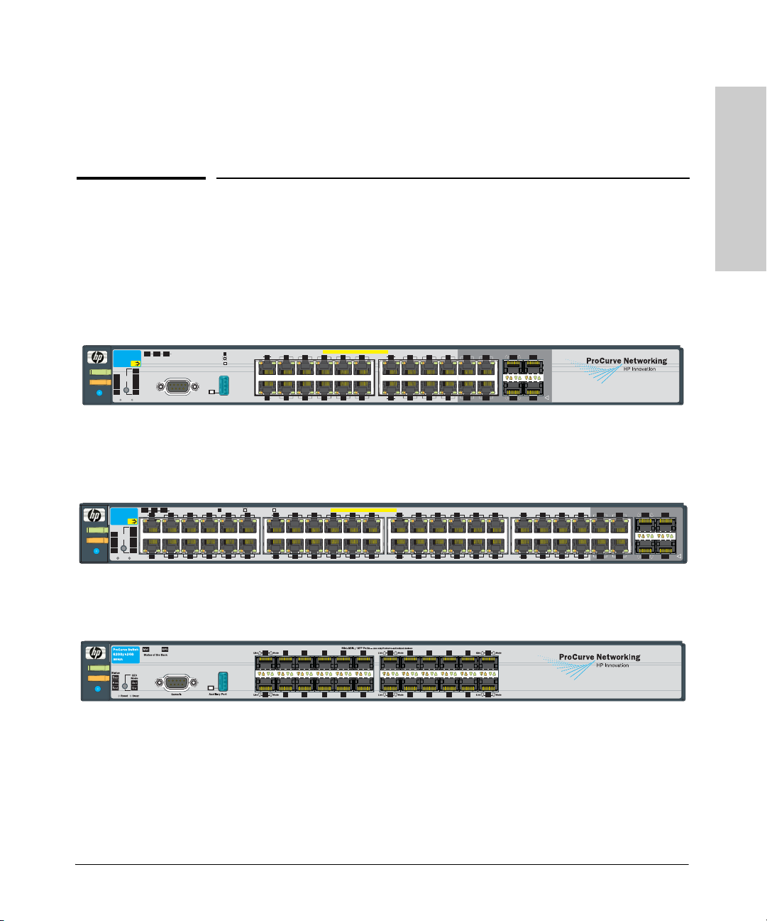
The Switch 3500yl-24G and Switch 3500yl-48G have respectively, 24 or 48,
auto-sensing 10/100/1000Base-TX RJ-45 ports, four dual-personality ports—
either auto-sensing 10/100/1000Base-T RJ-45 or mini-GBIC.
1-1
Page 10

Introducing the Switch
One slot is provided in the back of the device to support a four port (two fixed
CX4 ports and two X2 transceiver ports) 10 Gigabit per second Ethernet (10GbE) module to provide box connectivity to other switch boxes, to a 10
Gigabit per second concentrator or to any Ethernet compatible uplink.
The Series 3500yl Switches are also designed to support Power over Ethernet
(PoE) technology. The switches support 802.3af standard devices and some
pre-standard PoE devices. For a list of these devices, see the FAQs for your
switch model. This feature is the default and you must disable it if you do not
Introducing the Switch
want to use it. (Refer to the Management and Configuration Guide which is
on the ProCurve Web site, www.procurve.com. (See page 5-1 for details.)
The dual-personality ports have either auto-sensing 10/100/1000Base-T RJ-45,
or mini-GBIC connectivity. The mini-GBIC ports do not support PoE. If any of
the mini-GBIC ports are used the corresponding RJ-45 port will not be supplied
with PoE power and will be disabled. For more information regarding the PoE
capabilities of the Series 3500yl Switches, see the ProCurve Power over
Ethernet (PoE) for zl and yl Products Planning and Implementation Guide.
The Series 3500yl Switches can be connected to a ProCurve 620 Redundant
and External Power Supply (RPS/EPS) and receive redundant power from
that unit. If the internal power supply in the switch fails, the RPS/EPS unit will
immediately provide all the power necessary to keep the switch running. This
includes power to run the switch and PoE power. If maximum PoE power is
being used on all 48 ports, a 620 RPS/EPS is necessary just to provide full
power to the second 24 ports, and in this case, there is no redundancy.
1-2
The Series 6200yl Switch can be connected to the ProCurve 620 Redundant
and External Power Supply (RPS/EPS) and receive redundant power from
that unit. If the internal power supply in the switch fails, the RPS/EPS unit will
immediately provide all the power necessary to keep the switch running. This
only includes power to run the switch. The 6200yl does not support PoE power.
These switches are designed to be used primarily as a high-density wiring
closet or desktop switch. These switches can directly connect computers,
printers, and servers to provide dedicated bandwidth to those devices, and
can build a switched network infrastructure by connecting the switch to hubs,
other switches, or routers. In addition, the Series 3500yl Switches offer full
network management capabilities.
This chapter describes the Series 3500yl and 6200yl Switches, including:
■ Front and back of the switches
■ Switch features
Page 11
Introducing the Switch
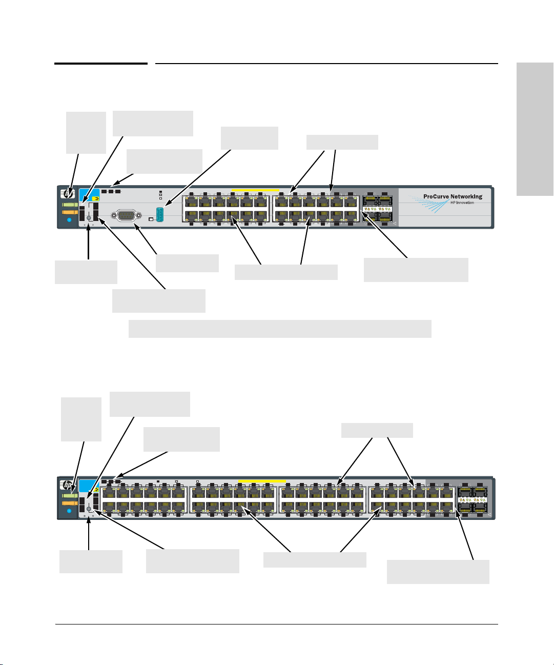
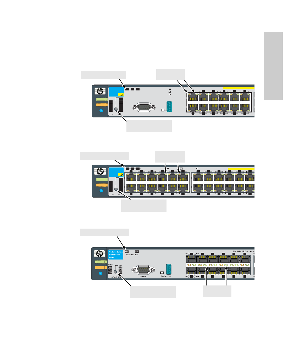
Front of the Switch
Power,
Fault, and
Locator
LEDs
ProCurve Switch
Mdl
3500yl-24G
J8692A
PoE
Act
Status
PoE
FDx
Power
LED
Mode
Spd
Tmp
*
Fan
PoE
Fault
Test
Usr
Locator
Reset
Clear
Reset and Clear
buttons
Front of the Switch
PoE, Temp, Fan, and
Test Status LEDs
Module, EPS, and
RPS, Status LEDs
Status of the Back
RPS
EPS
Spd mode: off = 10 Mbps
*
Auxiliary Port
Console
flash = 100 Mbps
on = 1000 Mbps
Link
Mode
1
Link
Mode
2
Console port*
Port LED Mode select
button and indicator LEDs
*On the 3500yl-48G switch, the Console and Auxiliary ports are located on the back of the unit.
Figure 1-1. Front of the ProCurve Switch 3500yl-24G.
Auxiliary port
and LED*
PoE-Integrated 10/100/1000Base-T Ports (1 - 24T) Ports are IEEE Auto MDI/MDI-X
7
5
3
86
4
10
10/100/1000Base-T RJ-45
Switch port LEDs
Dual-Personality Ports: 10/100/1000-T (T) or Mini-GBIC (M)
Link
Mode
9
13
11
12
15
17
19
Mode
Link
16
14
18 20
21T
22T 24T
Link Mode
23T
21
M
Link Mode
22M
(1000Base-T* or mini-GBIC)
23M
Use only one (T or M) for each Port
!
24M
Dual-personality ports
Introducing the Switch
Power,
Fault, and
Locator
LEDs
Mdl
EPS
ProCurve Switch
Link
1
3500yl-48G
J8692A
PoE
Act
Status
FDx
PoE
Power
LED
Mode
Spd
Tmp
*
PoE
Fan
Fault
Usr
Test
Locator
Link
2
Reset
Clear
Reset and Clear
buttons
PoE, Temp, Fan, and
Test Status LEDs
Module, EPS, and
RPS, Status LEDs
Spd mode: off = 10 Mbps, flash = 100 Mbps, on = 1000 Mbps
Status of the Back
RPS
Mode
Mode
*
7
5
3
4
9
10
6
8
Port LED Mode select
button and indicator LEDs
Figure 1-2. Front of the ProCurve Switch 3500yl-48G.
Switch port LEDs
Link
Mode
11
Link
Mode
12
14
PoE-Integrated 10/100/1000Base-T Ports (1 - 48T) Ports are IEEE Auto MDI/MDI-X
1917
1513
16
18
2220
Link
Mode
2321
24
2725
29
31
Link
Mode
26
30
28
3432
Mode
Link
39
37
3533
Mode
Link
38
36
40
10/100Base-TX RJ-45 ports*
Dual-Personality Ports: 10/100/1000-T (T) or Mini-GBIC (M)
41
43
42
44
Link
47T
48T
45M
Link Mode
46M 48M
45T
46T
Dual-personality ports
Mode
47M
Use only one (T or M) for each Port
!
(1000Base-T* or mini-GBIC)
1-3
Page 12
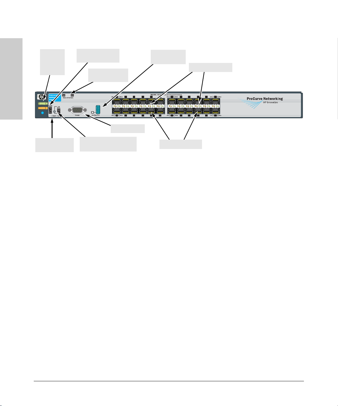
Introducing the Switch
Front of the Switch
Power,
Fault, and
locator
LEDs
Introducing the Switch
Power
Fault
Locator
Reset and Clear
buttons
Temp, Fan, and Test
Status LEDs
Module and RPS
Status LEDs
Console port
Port LED Mode select
button and indicator LEDs
Auxiliary port
and LED
Switch port LEDs
Mini-GBIC ports
ProCurve Switch 6200yl-24G
Figure 1-3. Front of the ProCurve Switch 6200yl-24G.
Network Ports
■ 24 or 48 auto-sensing 10/100/1000Base-T ports.
All these ports have the “HP Auto MDIX” feature, which means you can
use either straight-through or crossover twisted-pair cables to connect
any network devices to the switch.
■ On the Series 3500yl devices there are four dual-personality ports. Use
either the 10/100/1000Base-T RJ-45 connector, or install a supported
ProCurve mini-GBIC for fiber-optic connections.
1-4
The RJ-45 connectors support the IEEE Auto MDI/MDI-X feature, which
means you can use either straight-through or crossover twisted-pair
cables to connect any network device to the switch.
Dual-Personality Port Operation. By default, the RJ-45 connectors are
enabled. If a mini-GBIC is installed in a slot, it is enabled and the associated RJ-45 connector is disabled and cannot be used. If the mini-GBIC is
removed, the associated RJ-45 port is automatically re-enabled.
The RJ-45 connector also supplies PoE power until a mini-GBIC is
installed. The PoE power is turned off when a mini-GBIC is plugged in.
■ One, 10 gigabit expansion slot. These switches provide a single slot in the
back of the device that can accept a 4 x 10 gigabit transceiver module. The
module provides four 10 gigabit ports. The module provides either copper
or fiber optic media that conforms to the gigabit Ethernet standard as well
as dual 10 gigabit copper or uplink ports.
Page 13

Introducing the Switch
Front of the Switch
Switch
LEDs
Power
(green)
Fault
(orange)
Locator
(Blue)
Te st
(green)
LEDs
Table 1-1. Switch LEDs
State Meaning
On
Off
Off The normal state; indicates there are no fault conditions on the switch.
blink
orange*
On On briefly after the switch is powered on or reset, at the beginning of switch self test.
Off The normal operational state; the switch is not undergoing self test.
On The switch self test and initialization are in progress after the switch has been power
The switch is receiving power.
The switch is NOT receiving power.
A fault has occurred on the switch, one of the switch ports, module in the rear of the
switch, or the fan. The Status LED for the component with the fault will blink
simultaneously.
If this LED is on for a prolonged time, the switch has encountered a fatal hardware
failure, or has failed its self test. See chapter 4, “Troubleshooting” for more information.
Reserved for future development
cycled or reset. The switch is not operational until this LED goes off. The Self Test LED
also comes on briefly when you “hot swap” a mini-GBIC into the switch; the mini-GBIC
is self tested when it is hot swapped.
Introducing the Switch
Port LEDs
(green –
Link and
Mode)
LED Mode
View
(green)
blink green* A component of the switch has failed its self test. The status LED for that component,
for example an RJ-45 port, and the switch Fault LED will blink simultaneously.
Link Indicates the port LEDs are displaying link information:
• if the port LED is on, the port is enabled and receiving a link indication from the
connected device.
• if the port LED is off, the port has no active network cable connected, or is not
receiving link beat or sufficient light. Otherwise, the port may have been disabled
through the switch console, the web browser interface, or ProCurve Manager.
if the port LED is blinking* (orange) simultaneously with the Fault LED, the
corresponding port has failed its self test.
Mode The operation of the Mode LED is controlled by the LED Mode select button, and the
current setting is indicated by the LED Mode indicator LEDs near the button. Press the
button to step from one view mode to the next. The default view is Activity (Act).
Act Indicates the port LEDs are displaying network activity information.
FDx Indicates port LEDs are lit for ports in Full Duplex Mode. Off indicates ½ duplex.
1-5
Page 14

Introducing the Switch
Front of the Switch
Switch
State Meaning
LEDs
Spd Indicates the port LEDs are displaying the connection speed at which each port is
operating:
• if the port LED is off, the port is operating at 10 Mbps.
• if the port LED is blinking**, the port is operating at 100 Mbps.
• if the port LED is on continuously, the port is operating at 1000 Mbps.
Introducing the Switch
PoE • If the Mode LED is on the port is providing PoE power.
• If the Mode LED is off the port is not providing PoE power.
• If the Link LED is on the port is enabled for PoE.
• If the Link LED is off the port is disabled for PoE.
• If the Link LED is blinking, the port has an error or the port is denied power due to
insufficient power.
Usr Reserved for future development
Mdl
(Module
Status,
green/
orange)
RPS Status
(green/
orange)
EPS Status
(green/
orange)
On
Blink orange
Off
On
Blink orange
Off
On
Blink orange
Off
Expansion module is plugged into expansion slot and operating correctly
Expansion module is plugged into expansion slot but has experienced a fault
Expansion module is not plugged into expansion slot
Normal operation. RPS is connected and operating correctly. RPS could be powering
the unit.
RPS is connected but has experienced a fault.
RPS is not connected or is not powered on.
Connected to an External Power Supply, and receiving power.
The External Power Supply is connected but has experienced a fault or is unplugged.
The switch is not connected to an EPS.
Fan Status
(green/
orange)
PoE Status
(green/
Orange)
On
Blink
orange*
On
Off
Blink
Normal operation, all fans are ok.
One of the unit’s fans has failed. The switch Fault LED will be blinking simultaneously.
When the switch is ready to start supplying PoE power.
Should be off only during the boot process.
If any port has a internal hardware failure
orange*
Te mp
Blink
orange
**
On Switch temperature is normal.
If any port is denied PoE power or detecting an external PD fault
(green/
Orange)
Auxiliary
(green)
Blink
orange**
An over temperature condition has been detected.
Reserved for future development
* The blinking behavior is an on/off cycle once every 1.6 seconds, approximately.
** The blinking behavior is an on/off cycle once every 0.5 seconds, approximately.
1-6
Page 15
Introducing the Switch
1
P
Front of the Switch
LED Mode Select Button and Indicator LEDs
The operation of the Mode LED is controlled by the LED Mode select button,
and the current setting is indicated by the LED Mode indicator LEDs near the
button. Press the button to step from one view mode to the next.
Expansion Module LED
Power
Fault
Locator
ProCurve Switch
3500yl-24G
J8692A
Status
PoE
LED
Mode
Tmp
Fan
Test
Reset
PoE
Act
FDx
Spd
*
PoE
Usr
Clear
Status of the Back
RPS
EPS
Mdl
Console
LED Mode select button
and indicator LEDs
Figure 1-4. Indicator LEDs on the ProCurve Switch 3500yl-24G.
Expansion Module LEDs
Status of the Back
RPS
Mdl
EPS
Link
Mode
3
1
PoE
Act
FDx
Spd
*
PoE
Usr
Link
Mode
2
Clear
4
Power
Fault
Locator
ProCurve Switch
3500yl-48G
J8692A
Status
PoE
LED
Mode
Tmp
Fan
Test
Reset
Port LEDs Link
and Mode
Spd mode: off = 10 Mbps
*
Auxiliary Port
flash = 100 Mbps
on = 1000 Mbps
Link
Link
Port LEDs Link
and Mode
Spd mode: off = 10 Mbps, flash = 100 Mbps, on = 1000 Mbps
*
7
5
6
8
11
9
12
10
Mode
1
3
Mode
2
4
Link
Mode
1513
Link
Mode
14
16
PoE-Integrated 10/100/1000Base-T Ports (
7
5
6
8
PoE-Integrated 10/100/1000Base-T
1917
18
20
9
11
10
12
2321
22
24
Introducing the Switch
LED Mode select button
and indicator LEDs
Figure 1-5. Indicator LEDs on the ProCurve Switch 3500yl-48G.
Expansion Module LEDs
Power
Fault
Locator
LED Mode select button
and indicator LEDs
Figure 1-6. Indicator LEDs on the ProCurve Switch 6200yl-24G
Port LEDs Link
and Mode
1-7
Page 16

Introducing the Switch
Front of the Switch
■ Each port has a Link LED. If it is lit, the port has a link. If the Link LED is
blinking, the port has failed its self test. The Fault and Self Test LEDs will
be blinking simultaneously.
■ If the Activity (Act) indicator LED is lit, each port LED displays activity
information for the associated port—it flickers as network traffic is
received and transmitted through the port.
■ If the Full Duplex (FDx) indicator LED is lit, the port LEDs light for those
ports that are operating in full duplex.
Introducing the Switch
■ If the Speed (Spd) indicator LED is lit, the port LEDs behave as follows
to indicate the connection speed for the port:
• Off = 10 Mbps
• blinking = 100 Mbps (the blinking behavior is a repeated on/off cycle
once every 0.5 sec.)
• On = 1000 Mbps
■ The Usr Mode LED is reserved for future development.
■ If the PoE indicator LED is lit, the Link and Mode LEDs indicate PoE
status.
Link LED:
• On = PoE is enabled on this port.
• Off = PoE is disabled on this port.
• Slow Blinking = Internal PoE fault on this port. or has been denied
power.
• Fast Blinking = This port is denied PoE power or has an external load
fault.
1-8
Mode LED:
• On = PoE power is be supplied on this port.
• Off = PoE is not being supplied on this port.
Reset Button
This button is used to reset the switch while it is powered on. This action clears
any temporary error conditions that may have occurred and executes the
switch self test. It is also used when restoring the switch factory default
configuration. See the Clear Button section, Restoring Factory Default
Configuration.
Page 17

Introducing the Switch
Front of the Switch
Clear Button
This button is used for these purposes:
■ Deleting Passwords - When pressed by itself for at least one second, the
button deletes any switch console access passwords that you may have
configured. Use this feature if you have misplaced the password and need
console access.
This button is provided for your convenience, but its presence means that
if you are concerned with the security of the switch configuration and
operation, you should make sure the switch is installed in a secure
location, such as a locked wiring closet.
■ Restoring Factory Default Configuration - When pressed with the
Reset button in a specific pattern, any configuration changes you may
have made through the switch console, the web browser interface, and
SNMP management are removed, and the factory default configuration is
restored to the switch. For the specific method to restore the factory
default configuration, see “Restoring the Factory Default Configuration”
on page 11, in chapter 4, “Troubleshooting” of this manual.
Expansion Module LEDs
“Expansion Module” LEDs refer to the LEDs specific to the expansion module.
These LEDs are located on the physical expansion module bulkhead. These
LEDs are only viewable in the rear of the Switch 3500yl-48G product on the
Expansion Slot Module itself. These LEDs are duplicated on the front panel
of the Switch 3500yl-24G and 6200yl-24G devices.
Introducing the Switch
1-9
Page 18
Introducing the Switch
Front of the Switch
Table 1-2. Expansion Module LEDs
Name Color Mode Description
Expansion Module LEDs per module
Module
(Mdl) Power
Green
On
Off
Expansion module is plugged into expansion slot and operating correctly
Expansion module's power has been turned OFF, and the card can be
removed from the box if necessary.
Introducing the Switch
Module
(Mdl) Fault
Expansion Module LEDs per port
Link Green On
Act Green On Indicates the port LEDs are displaying network activity information.
Orange
On
Off
blinking
Expansion module is plugged into expansion slot but has experienced a
fault
Indicates that the port LEDs are displaying link information:
• if the port LED is on, the port is enabled and receiving a link indication
from the connected device.
• if the port LED is off, the port has no active network cable connected,
or is not receiving link beat or sufficient light. Otherwise, the port may
have been disabled through the switch console, the web browser
interface, or ProCurve Manager.
• if the port LED is blinking* simultaneously with the Fault LED, the
corresponding port has failed its self test.
Expansion module LEDs operate in modes for Link and Activity. FDx and Spd
modes have no meaning for the 10-GbE ports on the expansion module.
Caution It is required the switch be powered down before inserting or extracting the
Expansion Module.
1-10
Page 19
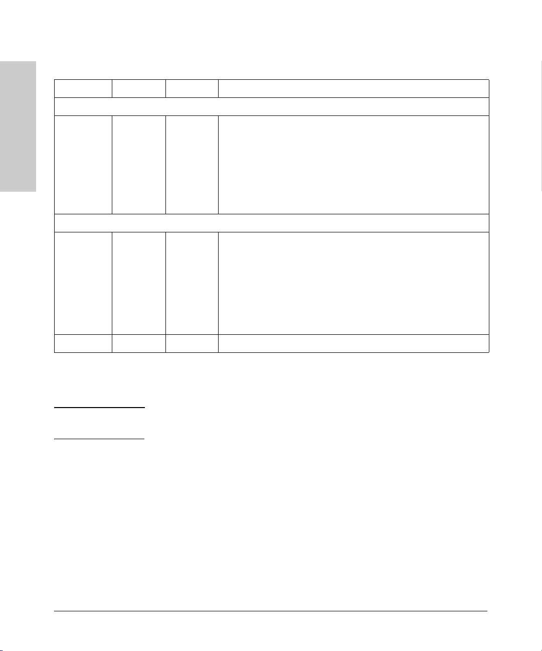
Introducing the Switch
Back of the Switch
Serial No.
System MAC
Address
Serial No.
System MAC
Address
0001e7
SG12345678
0001e7
123456
SG12345678
123456
yl module slot
Back of the Switch
EPS Input Port
CAUTION: MULTIPLE POWER SOURCES
Disconnect all AC power cords, and EPS and RPS
cables to completely remove power from the unit.
12V System Power (RPS) Input
RPS Input Port
Figure 1-7. Back of the ProCurve Switch 3500yl-24G.
EPS Input Port
CAUTION: MULTIPLE POWER SOURCES
Disconnect all AC power cords, and EPS and RPS
cables to completely remove power from the unit.
Console
Auxiliary Port
12V System Power (RPS) Input
PoE
50V PoE (EPS) Input
Connect ProCurve 620 EPS only
AC power connector
PoE
50V PoE (EPS) Input
Connect ProCurve 620 EPS only
Line: 50/60 Hz.
100-127 V~ 10 A
200-240 V~ 5 A
Line: 50/60 Hz.
100-127 V~ 10 A
200-240 V~ 5 A
Introducing the Switch
Serial No.
System MAC
Address
0001e7
SG12345678
123456
yl module slot
yl module slot
Console Port
Auxiliary Port and LED
RPS Input Port
Figure 1-8. Back of the ProCurve Switch 3500yl-48G.
Do Not Use
CAUTION: MULTIPLE POWER SOURCES
Disconnect all AC power cords, and EPS and RPS
cables to completely remove power from the unit.
12V System Power (RPS) Input
RPS Input Port
Figure 1-9. Back of the ProCurve Switch 6200yl-24G.
AC power connector
Line: 50/60 Hz.
100-127 V~ 10 A
200-240 V~ 5 A
AC power connector
1-11
Page 20

Introducing the Switch
Back of the Switch
yl Module Slot
These switches support one yl module. The yl module provides 4 ports:
■ two 10-GbE CX4 fixed copper ports
■ two 10-GbE flexible media slots that support a number of different
transceivers. See the ProCurve Switch yl Module Installation Guide for
more information on supported transceivers.
Introducing the Switch
RPS and EPS Input Port
The Series 3500yl and 6200yl Switches support connectivity to a redundant
power supply. The “ProCurve 620 Redundant and External Power Supply
(RPS/EPS) is an accessory product for these Switches. The RPS/EPS provides
redundant and additional PoE power to the switch products to back up the
power supply in the switch in case of loss of AC or PoE power. Or If maximum
PoE power is being used on all 48 ports, a 620 RPS/EPS will be necessary to
provide full power to the second 24 ports, and in this case, there would be no
redundancy.
Console Port
This port is used to connect a console to the switch by using the serial cable
supplied with the switch. This connection is described under “Connect a
Console to the Switch” in chapter 2, “Installing the Switch.” The console can
be a PC or workstation running a VT-100 terminal emulator, or a VT-100
terminal. The console port is located on the front of the 3500yl-24G and 6200yl24G, and on the back of the 3500yl-48G.
Power Connector
The Series 3500yl and 6200yl Switches do not have a power switch; they are
powered on when connected to an active AC power source. These switches
automatically adjust to any voltage between 100--240 volts and either 50 or 60
Hz. There are no voltage range settings required.
1-12
Page 21

Introducing the Switch
Switch Features
Switch Features
The features of the Series 3500yl and 6200yl Switches include:
■ 24 or 48 auto-sensing 10/100/1000Base-T RJ-45 ports with HP Auto-MDIX.
■ Four dual-personality ports—either the auto sensing 10/100/1000Base-T
RJ-45 or the mini-GBIC can be used for each port.
■ The 6200yl provides 24 mini-GBIC ports.
■ One slot (optional yl module slot) is provided in the back of the device to
support a series of transceivers to provide connectivity to other switch
boxes, to a 10 Gig concentrator or to any Ethernet compatible uplink.
■ The auxiliary port is reserved for future development.
■ The Switches can be connected to a ProCurve RPS/EPS and receive
redundant power from that unit. If the internal power supply in the switch
fails, the RPS/EPS unit will immediately provide all the power necessary
to keep the switch running.
■ Power over Ethernet (PoE) operation—the 3500yl switches are IEEE
802.af compliant and provide up to 15.4 W per port to power IP phones,
wireless access points, web cameras, and more. For more information,
see the PoE Planning and Implementation Guide for zl and yl Products.
■ Plug-and-play networking—all ports are enabled—just connect the
network cables to active network devices and your switched network is
operational.
■ IEEE 802.3ab Auto MDI/MDI-X on all 10/100/1000 twisted-pair ports,
meaning that all connections can be made using straight-through
twisted-pair cables. Cross-over cables are not required, although they
will also work. The pin operation of each port is automatically adjusted
for the attached device: if the switch detects that another switch or hub
is connected to the port, it configures the port as MDI; if the switch detects
that an end-node device is connected to the port, it configures the port as
MDI-X.
■ Automatic learning of the network addresses in each switch’s 8000-
address forwarding table, (with configurable address aging value).
■ Automatically negotiated full-duplex operation for the 10/100/1000 RJ-45
ports when connected to other auto-negotiating devices—the mini-GBIC
ports always operate at full duplex.
■ Easy management of the switch through several available interfaces:
• console interface—a full featured, easy to use, VT-100 terminal
interface that is especially good for out-of-band switch management
or for Telnet access to the switch.
Introducing the Switch
1-13
Page 22

Introducing the Switch
Switch Features
• web browser interface—an easy to use built-in graphical interface
that can be accessed from common web browsers.
• ProCurve Manager—an SNMP-based, graphical network management tool that you can use to manage your entire network. This
product is included with your new switch.
■ Support for the Spanning Tree Protocol to eliminate network loops
■ Support for up to 2048 IEEE 802.1Q-compliant VLANs so you can divide
the attached end nodes into logical groupings that fit your business needs.
Introducing the Switch
■ Support for many advanced features to enhance network performance—
for a description, see the Management and Configuration Guide, which
is on the ProCurve Web site at www.procurve.com. See page 5-1 for
details.
■ Download of new switch software for product enhancements or bug fixes.
■ Support for IEEE 802.3af Standard and Pre-standard PoE devices.
1-14
Page 23

Installing the Switch
The ProCurve Series 3500yl and 6200yl Switches come with an accessory kit
that includes the brackets for mounting the switch in a standard 19-inch telco
rack, in an equipment cabinet, and with rubber feet that can be attached so
the switch can be securely located on a horizontal surface. The brackets are
designed to allow mounting the switch in a variety of locations and orientations. For other mounting options contact your local ProCurve authorized
network reseller or ProCurve representative. This chapter shows how to
install the switch.
Caution If the switch is to be shipped in a rack, be sure to use only an HP 10K rack.
Mount the switch using rail kit, ProCurve 1U RK MT SWITCH 10K ALL, part
number 356578-B21 and shelf kit AB469A, HP rx 16/26 Factory Rackmount
Shelf Kit. Both kits must be used. Otherwise you will void the warranty.
2
Installing the Switch
Included Parts
The Series 3500yl and 6200yl Switches have the following components shippe d
with them:
■ ProCurve Series 3500yl and 6200yl Switches Installation and Getting
Started Guide, this manual
■ ProCurve Manager - CD ROM and booklet
■ Read Me First
■ Customer Support/Warranty booklet
■ Console cable
2-1
Page 24

Installing the Switch
Included Parts
■ Accessory kit
(5069-5705) for both the Series
3500yl and 6200yl Switches
two mounting brackets
eight 8-mm M4 screws to attach the
mounting brackets to the switch
four 5/8-inch number 12-24 screws to
attach the switch to a rack
four rubber feet
■ Power cord, one of the following:
Installing the Switch
Japan Power
Cord Warning
Australia/New Zealand
China
Continental Europe
Denmark
Japan
Switzerland
United Kingdom/Hong Kong/Singapore
United States/Canada/Mexico
South Africa and India
Argentina
Brazil and Thailand
Chile
Taiwan
Israel
8121-0857
8121-1034
8120-5336
8120-5340
8120-5342
8120-5339
8120-5334
8121-0973
8120-5341
8120-8375
8121-0671
8120-8389
8121-0941
8121-1009
Please use the power cord supplied with your product. This power cord
is not to be used with other products.
2-2
Page 25

Installing the Switch
Installation Procedures
Installation Procedures
Summary
1. Prepare the installation site (page 2-5). Ensure the physical environment is properly prepared, including having the correct network cabling
ready to connect to the switch and having an appropriate location for the
switch. See page 2-4 for some installation precautions.
2. Install or remove a yl module (optional—page 2-7).
3. Install or remove a transceiver (optional—(page 2-8). If you have
installed a yl module, you can now install one or two transceivers.
4. Install or remove mini-GBICs (optional—page 2-9). The switch has
four slots for installing mini-GBICs. Depending on where you will mount
the switch, it may be easier to install the mini-GBICs first. Mini-GBICs can
be installed or removed while the switch is powered on.
5. Verify the switch passes self test (page 2-11). Plug the switch into a
power source and observe that the LEDs on the switch’s front panel
indicate correct switch operation. When self test is complete, unplug the
switch.
6. Mount the switch (page 2-13). The Switch can be mounted in a 19-inch
telco rack, in an equipment cabinet, or on a horizontal surface.
7. Connect the switch to a power source (page 2-15). Once the switch is
mounted, plug it into the nearby main power source.
8. Connect the network cables (page 2-16). Using the appropriate
network cables, connect the network devices to the switch ports.
9. Connect a 620 RPS/EPS (optional—page 2-18). You may wish to use
a 620 RPS/EPS with your switch. To do so you must connect the external
power supply using the RPS or EPS cables supplied with the 620 RPS/EPS.
10. Connect a console to the switch (optional—page 2-22). You may wish
to modify the switch’s configuration, for example, to configure an IP
address so it can be managed using a web browser, from an SNMP network
management station, or through a Telnet session. Configuration changes
can be made easily by using the included console cable to connect a PC
to the switch’s console port.
Installing the Switch
At this point, the switch is fully installed. See the rest of this chapter if you
need more detailed information on any of these installation steps.
2-3
Page 26

Installing the Switch
Installation Procedures
Installation Precautions:
Follow these precautions when installing the Series 3500yl or 6200yl Switches.
WARNING ■ The rack or cabinet should be adequately secured to prevent it
from becoming unstable and/or falling over.
■ Devices installed in a rack or cabinet should be mounted as low as
possible, with the heaviest devices at the bottom and progressively
lighter devices installed above.
■ Neither the Right or Left sides of the switch can be placed down-
ward. (That is, the right or left side of the unit while facing the
front.)
Cautions ■ If the switch is to be shipped in a rack, be sure to use only an HP 10K rack.
Mount the switch using rail kit part number 356578-B21 and shelf kit
AB469A. Both kits must be used. Otherwise you will void the warranty.
■ Ensure the power source circuits are properly grounded, then use the
power cord supplied with the switch to connect it to the power source.
Installing the Switch
■ If your installation requires a different power cord than the one supplied
with the switch and power supply, be sure the cord is adequately sized for
the switch’s current requirements. In addition, be sure to use a power cord
displaying the mark of the safety agency that defines the regulations for
power cords in your country. The mark is your assurance that the power
cord can be used safely with the switch and power supply.
■ When installing the switch, the AC outlet should be near the switch and
should be easily accessible in case the switch must be powered off.
■ Ensure the switch does not overload the power circuits, wiring, and over-
current protection. To determine the possibility of overloading the supply
circuits, add together the ampere ratings of all devices installed on the
same circuit as the switch and compare the total with the rating limit for
the circuit. The maximum ampere ratings are usually printed on the
devices near the AC power connectors.
■ Do not install the switch in an environment where the operating ambient
temperature might exceed 55°C (131°F)
■ Ensure the air flow around the sides and back of the switch is not
1
.
restricted.
1
If you are installing either of the Series 3500yl or 6200yl Switches with an X2 transceiver installed,
the operating ambient temperature should not exceed 40°C (104°F). See transceiver
specifications in the ProCurve Switch yl Module Installation Guide.
2-4
Page 27

1. Prepare the Installation Site
Cabling Infrastructure - Ensure the cabling infrastructure meets the
necessary network specifications. The copper ports accept CX4 cable with
Infiniband-style connectors or fiber cable using a CX4 optical media converter
(OMC). The fiber ports accept single-mode fiber optic cable with SC
connectors. See the following table for cable types and lengths, and see
Appendix B “Switch Ports and Network Cables” for more information:
Table 2-1. Summary of Cable Types to Use With the Switch
Port Type Cable Type Length Limits
Installing the Switch
Installation Procedures
Twisted-Pair Cables
10/100/1000Base-T For either 10, 100 Mbps, or 1000 Mbps
CX4 Speed 3.125Gbx4
OMC CX4 Fiber
(Optical Media
Converter)
operation:
Category 5 or better, 100-ohm UTP or shielded
twisted-pair (STP) balanced cable. For
1000 Mbps (gigabit) operation, Category 5e
cabling or better is recommended.
Copper Cables
(Cables compatible with the 802.1ak standard)
12 fiber 50/125 μm (core/cladding) diameter,
multimode Fiber ribbon cable. 12 fiber 62.5/125
μm (core/cladding) diameter, multimode Fiber
ribbon cable is also supported.
Installing the Switch
100 meters
Note: The Series 3500yl and 6200yl Switches
are compatible with the IEEE 802.3ab standard
including the “Auto MDI/MDI-X” feature,
which allows use of either straight-through or
crossover twisted-pair cables for connecting
to any network devices including end nodes,
such as computers, or to other switches, hubs,
and routers.
Note: For 1000 Mbps operation, all four wire
pairs are used for data transmission.
0.5-15 meters
150 Mhz/km = 1-50 meters
500 Mhz/km = 1-100 meters
2000 Mhz/km = 1-300 meters
2-5
Page 28

Installing the Switch
Installation Procedures
Port Type Cable Type Length Limits
Fiber Optic Cables
Installing the Switch
Gigabit-SX
(on Gigabit-SX-LC
mini-GBIC)
Multimode fiber-optic cables designed for
Gigabit Ethernet: 62.5/125 μm or 50/125 μm
(core/cladding) diameter, 850 nm, low metal
content, graded-index cables, fitted with LC
connectors. The cables must comply with the
ITU-T G.651 and ISO/IEC 793-2 Type A1b or A1a
standards.
Gigabit-LX
(on Gigabit-LX-LC
mini-GBIC)
Single-mode fiber-optic cables designed for
Gigabit Ethernet: 9/125 μm (core/cladding)
diameter, 1310 nm, low metal content cables,
fitted with LC connectors. The cables must
comply with the ITU-T G.652 and ISO/IEC 793-2
Type B1 standards.
The multimode cables specified for the GigabitSX mini-GBIC may also be used, but a modeconditioning patch cord may be needed — see
“Mode Conditioning Patch Cord for Gigabit-LX”
on page B-3 for more information.
Gigabit-LH
(on Gigabit-LH-LC
Single-mode fiber-optic cables designed for
Gigabit Ethernet and fitted with LC connectors.
mini-GBIC)
10-GbE SR Multimode fiber-optic cable designed for
Gigabit Ethernet: 62.5/125 μm (core/cladding)
diameter or 50/125 μm, 850 nm, low metal
content, complying with the ITU-T G.652 and
ISO/IEC 793-2 Type B1 standards.
• 62.5 μm cable:
– 160 MHz/km = 220 meters
– 200 MHz/km = 275 meters
•50 μm cable:
– 400 MHz/km = 500 meters
– 500 MHz/km = 550 meters
• single-mode cable = 5 kilometers
• multimode cable = 550 meters
• single-mode cable = 70 kilometers
■ 62.5 μm cable:
• 160 Mhz/km = 2-26 meters
• 200 Mhz/km = 2-33 meters
■ 50 μm cable:
• 400 Mhz/km = 2-66 meters
• 500 Mhz/km = 2-82 meters
• 2000 Mhz/km = 2-300 meters
10-GbE LR 9/125 μm (core/cladding) diameter, 1310 nm,
low metal content, single mode fiber-optic
cables, complying with the ITU-T G.652 and
ISO/IEC 793-2 Type B1 standards.
10-GbE ER 9/125 μm (core/cladding) diameter, 1550 nm,
low metal content, single mode fiber-optic
cables, complying with the ITU-T G.652 and
ISO/IEC 793-2 Type B1 standards.
Note: Conditioning patch cord cables are not supported on 10-GbE speeds.
2-6
single-mode cable: 2-10 kilometers
single-mode cable: 2-30 kilometers (40
kilometers, on an engineered fiber optic link
that meets standards in the specification).
Page 29
Installing the Switch
Installation Procedures
■ Installation Location - Before installing the switch, plan its location and
orientation relative to other devices and equipment:
• In the front of the switch, leave at least 7.6 cm (3 inches) of space for
the twisted-pair and fiber-optic cabling.
• In the back of the switch, leave at least 3.8 cm (1 1/2 inches) of space
for the power cord.
• On the sides of the switch, leave at least 7.6 cm (3 inches) for cooling,
except if the switch is installed in an open EIA/TIA rack.
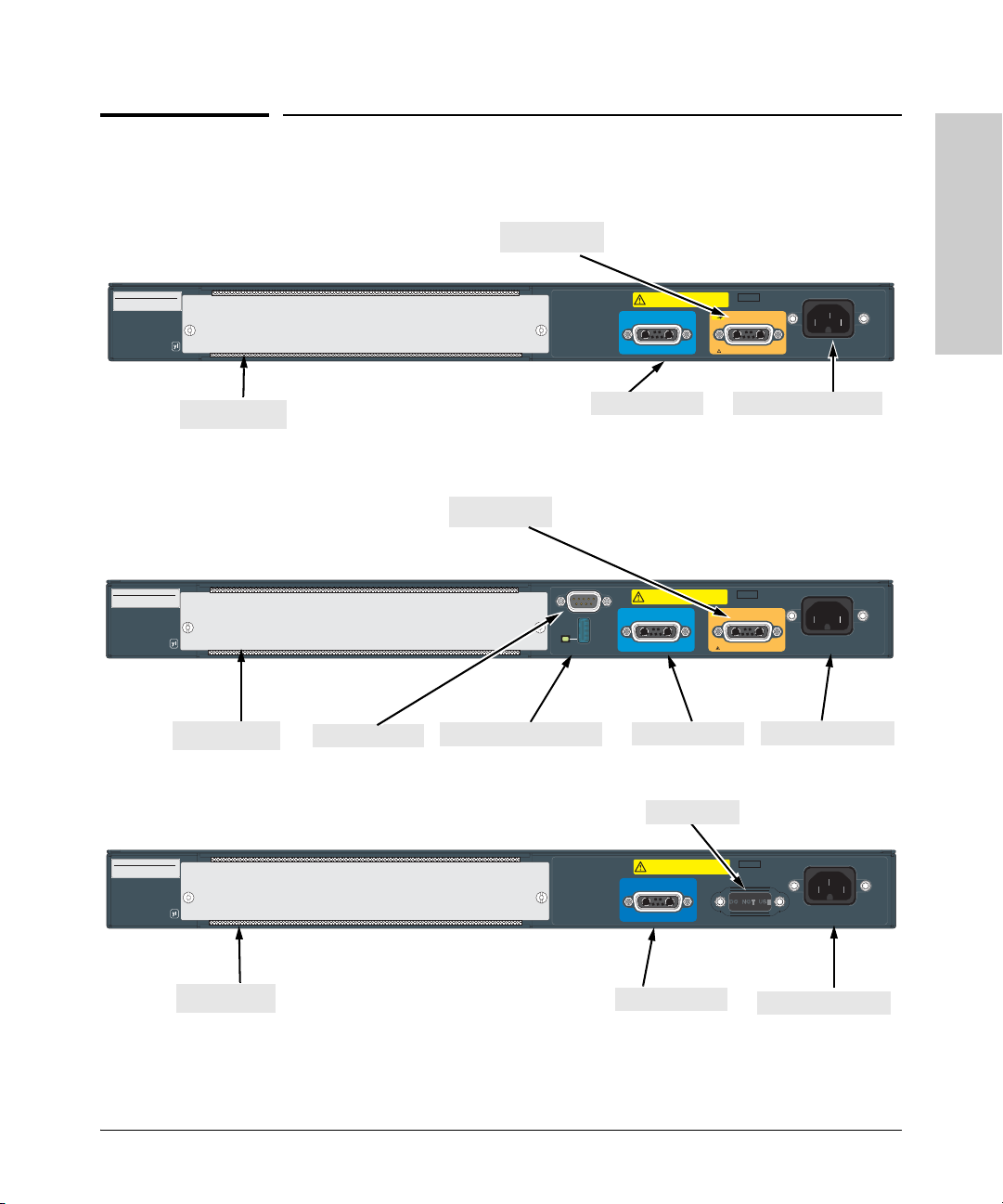
2. (Optional) Install or Remove a yl Module
Note Hot swapping modules is not supported. If a module is installed or removed
with the switch powered on, a reset will occur. Only insert or remove a module
during scheduled downtime with the switch powered off.
1. Remove the cover plate
2. Insert the module aligning with the guides in the slot.
3. Once the contacts have engaged, use the extractor handles to seat the
module completely.
4. Tighten the captive screws. Refer to the yl Module Installation Guide for
more details.
Align the edges of the board with guides
Installing the Switch
Figure 2-1. Installing a yl module.
Caution For proper cooling and reduction of electromagnetic emissions, ensure a slot
cover is installed on any unused slot.
2-7
Page 30
Installing the Switch
Installing the Switch
Installation Procedures
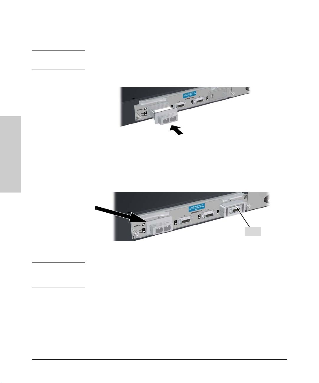
3. (Optional) Install or Remove a Transceiver
Note Hot swapping transceivers is supported. You can install or remove a trans-
ceiver with the switch powered on, a reset will not occur.
a. Slide the transceiver in until it stops.
Figure 2-2. Installing a fiber optic transceiver.
1
If you are installing either of the Series 3500yl or 6200yl Switches with an X2 transceiver installed,
the operating ambient temperature should not exceed 40°C (104°F). See transceiver
specifications in the ProCurve Switch yl Module Installation Guide.
b. Push firmly until the gasket seats against the bulkhead.
1
Bail
Figure 2-3. Securing a transceiver bail.
Note When switch power is on, the Link and Activity LEDs will come on for
approximately two seconds and then go off. This is confirmation the transceiver is completely seated.
c. If your transceiver has a bail, move the bail up, if not your transceiver is
now completely installed. Refer to the ProCurve Switch yl Module Installa-
tion Guide for more details.
To remove the transceiver:
If your transceiver has a bail, lower the bail until it is approximately horizontal,
and then using the bail, pull the transceiver from the slot. If your transceiver
does not have a bail, pull the transceiver straight out.
2-8
Page 31

Installing the Switch
Installation Procedures
4. (Optional) Install or Remove mini-GBICs
You can install or remove a mini-GBIC from a mini-GBIC slot without having
to power off the switch. Use only ProCurve mini-GBICs.
Notes ■ The mini-GBIC slots are shared with the four 10/100/1000Base-T RJ-45
ports. If a mini-GBIC is installed in a slot, the associated RJ-45 port is
disabled and cannot be used.
■ The mini-GBIC ports operate only at full duplex. Half duplex operation is
not supported.
■ Ensure the network cable is NOT connected when you install or remove
a mini-GBIC.
When this manual was printed, the supported mini-GBICs include the
following:
■ ProCurve Gigabit-SX-LC mini-GBIC (J4858B)
■ ProCurve Gigabit-LX-LC mini-GBIC (J4859B)
■ ProCurve Gigabit-LH-LC mini-GBIC (J4860B)
Caution Use only supported genuine ProCurve mini-GBICs with your switch. Non-
ProCurve mini-GBICs are not supported, and their use may result in product
malfunction. Should you require additional ProCurve mini-GBICs, contact
your ProCurve Networking Sales and Service Office or authorized dealer.
Installing the Switch
Installing the mini-GBICs:
Hold the mini-GBIC by its sides and gently insert it into either of the slots on
the switch until the mini-GBIC clicks into place.
WARNING The ProCurve mini-GBICs are Class 1 laser devices. Avoid direct eye
exposure to the beam coming from the transmit port.
Figure 2-4. Installing a mini-GBIC.
2-9
Page 32

Installing the Switch
Installing the Switch
Installation Procedures
Removing the mini-GBICs:
Note You should disconnect the network cable from the mini-GBIC before removing
it from the switch.
Depending on when you purchased your ProCurve mini-GBIC, it may have
either of three different release mechanisms: a plastic tab on the bottom of
the mini-GBIC, a plastic collar around the mini-GBIC, or a wire bail.
To remove the mini-GBICs that have the plastic tab or plastic collar, push the
tab or collar toward the switch until you see the mini-GBIC release from the
switch (you can see it move outward slightly), and then pull it from the slot.
To remove the mini-GBICs that have the wire bail, lower the bail until it is
approximately horizontal, and then using the bail, pull the mini-GBIC from the
slot.
2-10
Page 33
Installing the Switch
Installation Procedures
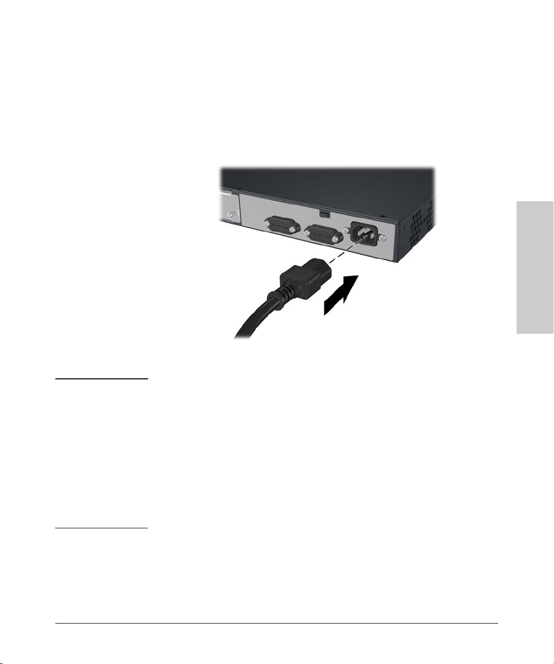
5. Verify the Switch Passes Self Test
Before mounting the switch in its network location, you should first verify it
is working properly by plugging it into a power source and verifying it passes
self test.
1. Connect the power cord supplied with the switch to the power connector
on the back of the switch, and then into a properly grounded electrical
outlet.
Installing the Switch
Figure 2-5. Connecting the power cord.
Note The Series 3500yl and 6200yl Switches do not have a power switch. They are
powered on when the power cord is connected to the switch and to a power
source. For safety, the power outlet should be located near the switch
installation.
The switch automatically adjusts to any voltage between 100-127 and 200-240
volts and either 50 or 60 Hz. No voltage range settings are required.
If your installation requires a different power cord than the one supplied with
the switch, be sure to use a power cord displaying the mark of the safety
agency that defines the regulations for power cords in your country. The mark
is your assurance that the power cord can be used safely with the switch.
2-11
Page 34
Installing the Switch
Installation Procedures
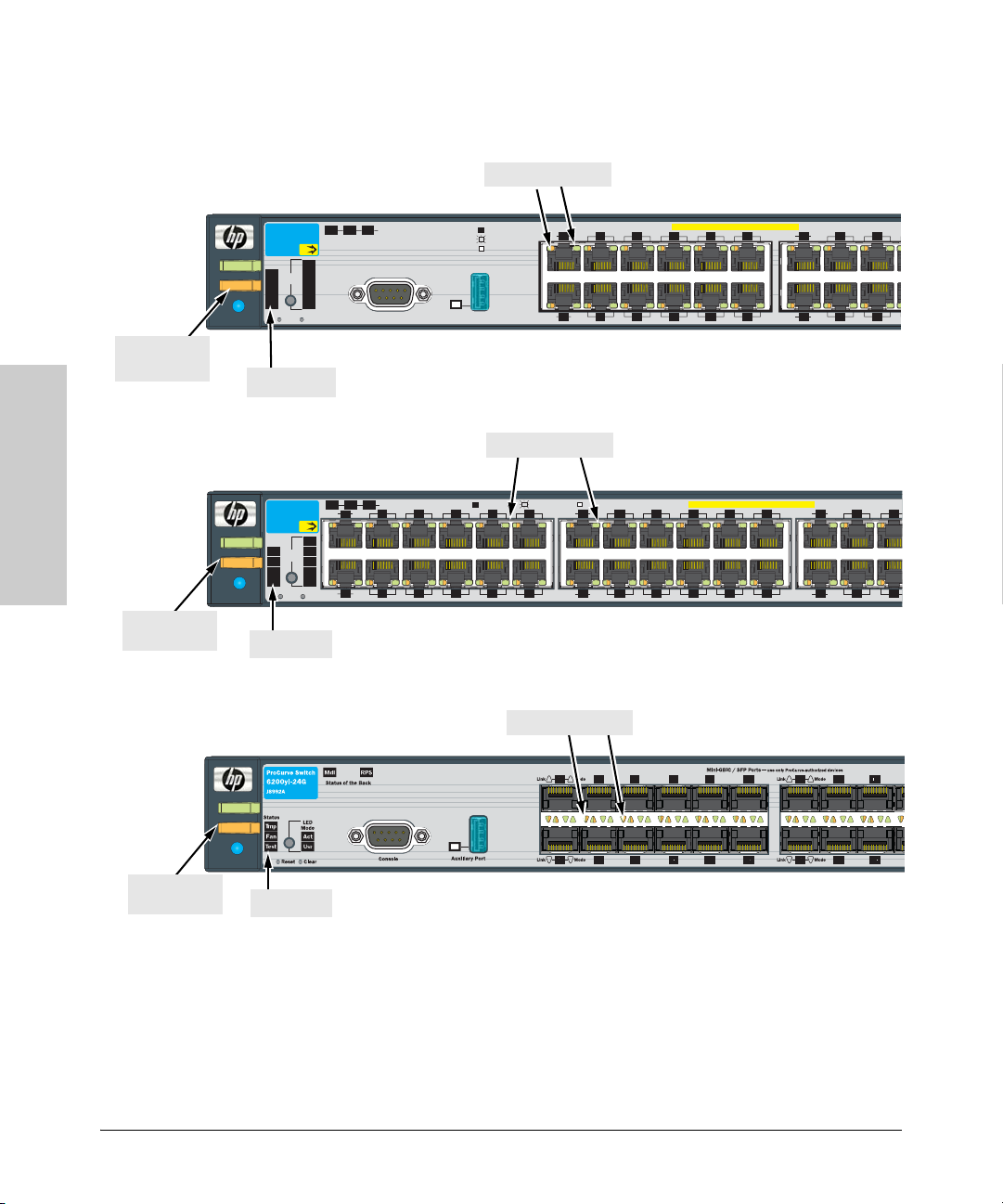
2. Check the LEDs on the switch as described below.
Installing the Switch
Power and
Fault LEDs
Power and
Fault LEDs
Power
Fault
Locator
Power
Fault
Locator
ProCurve Switch
3500yl-24G
J8692A
Status
PoE
LED
Mode
Tmp
Fan
Test
Reset
Tes t LED
ProCurve Switch
3500yl-48G
J8692A
Status
PoE
LED
Mode
Tmp
Fan
Test
Reset
Tes t LED
Switch port LEDs
Status of the Back
RPS
EPS
Mdl
PoE
Act
FDx
Spd
*
PoE
Usr
Clear
Console
Spd mode: off = 10 Mbps
*
flash = 100 Mbps
on = 1000 Mbps
Auxiliary Port
Link
Mode
1
3
Link
Mode
2
4
Switch port LEDs
Status of the Back
RPS
Mdl
EPS
Link
Mode
3
1
PoE
Act
FDx
Spd
*
PoE
Usr
Link
Mode
2
Clear
4
Spd mode: off = 10 Mbps, flash = 100 Mbps, on = 1000 Mbps
*
7
5
6
8
11
9
12
10
Link
Mode
Link
Mode
14
ProCurve Switch 3500yl-24G
PoE-Integrated 10/100/1000Base-T Ports (1 - 24T) Ports are IEEE Auto MDI/MDI-X
7
9
5
6
8
11
10
12
ProCurve Switch 3500yl-48G
PoE-Integrated 10/100/1000Base-T Ports (1 - 48T) Ports are IEEE Auto MDI/MDI-X
1513
16
1917
18
20
22
Link
Mode
13
15
17
Mode
Link
16
14
Link
2321
Link
26
24
18
Mode
2725
29
Mode
30
28
2-12
Power and
Fault LEDs
Power
Fault
Locator
Switch port LEDs
ProCurve Switch 6200yl-24G
Test LED
Figure 2-6. LEDs on the yl switches.
When the switch is powered on, it performs its diagnostic self test. Self
test takes approximately 50 seconds to complete.
Page 35

Installing the Switch
Installation Procedures
LED Behavior:
During the self test:
• Initially, all the status, LED Mode and port LEDs are on for most of
the duration of the test.
• Most of the LEDs go off and then may come on again during phases
of the self test. For the duration of the self test, the Test LED stays on.
When the self test completes successfully:
•The Power and Fan Status LEDs remain on.
•The Fault and Test LEDs go off.
• The port LEDs on the front of the switch go into their normal operational mode:
– If the ports are connected to active network devices, the LEDs
behave according to the LED Mode selected. In the default view
mode (Link), the LEDs should be on.
– If the ports are not connected to active network devices, the LEDs
will stay off.
If the LED display is different than what is described above, especially if
the Fault and Test LEDs stay on for more than 60 seconds or they start
blinking, the self test has not completed correctly. Refer to chapter 4,
“Troubleshooting” for diagnostic help.
Installing the Switch
6. Mount the Switch
After the switch passes self test, you are ready to mount the switch in a stable
location. The Series 3500yl and 6200yl Switches can be mounted in these ways:
■ in a rack or cabinet
■ on a horizontal surface
For other mounting options contact your local ProCurve authorized network
reseller or ProCurve representative.
Rack or Cabinet Mounting
These switches are designed to be mounted in any EIA-standard 19-inch telco
rack or communication equipment cabinet.
WARNING For safe operation, please read the mounting precautions on
page 2-4, before mounting a switch.
2-13
Page 36
Installing the Switch
Installation Procedures
Installing the Switch
Equipment
Cabinet
Note
The 12-24 screws supplied with the switch are the correct threading for
standard EIA/TIA open 19-inch racks. If you are installing the switch in an
equipment cabinet such as a server cabinet, use the clips and screws that came
with the cabinet in place of the 12-24 screws that are supplied with the switch.
Complete step 1, and plan which four holes you will be using in the cabinet
and install all four clips. Then proceed to step 2.
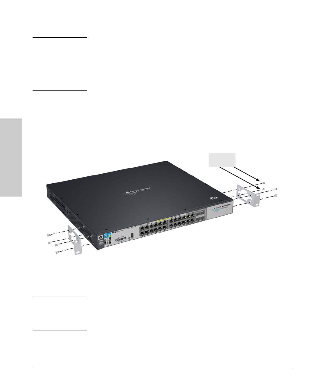
Rack Mounting the Switch 3500yl-24G
1. Use a #1 Phillips (cross-head) screwdriver and attach the mounting
brackets to the switch with the included 8-mm M4 screws.
8 mm
M4 screws
Figure 2-7. Attaching the mounting brackets to the switch.
Note The mounting brackets have multiple mounting holes and can be rotated
allowing for a wide variety of mounting options. These include mounting the
switch so its front face is flush with the face of the rack, or mounting it in a
more balanced position as shown in the illustration.
2-14
Page 37
Installing the Switch
Installation Procedures
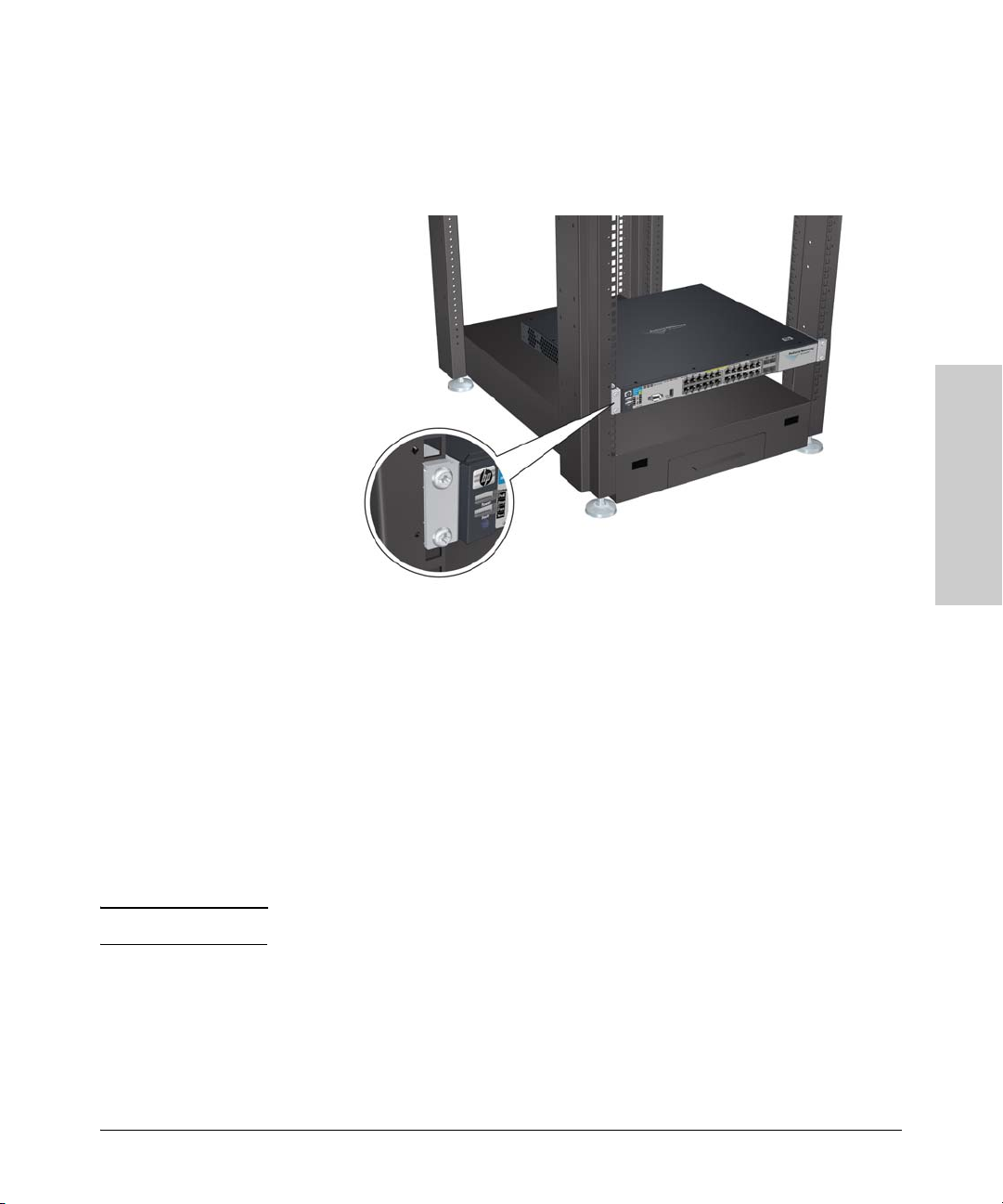
2. Hold the switch with attached brackets up to the rack and move it
vertically until rack holes line up with the bracket holes, then insert and
tighten the four number 12-24 screws holding the brackets to the rack.
Installing the Switch
Figure 2-8. Mounting the switch in a rack.
Horizontal Surface Mounting
Place the switch on a table or other horizontal surface. The switch comes with
rubber feet in the accessory kit that can be used to help keep the switch from
sliding on the surface.
Attach the rubber feet to the four corners on the bottom of the switch within
the embossed angled lines. Use a sturdy surface in an uncluttered area. You
may want to secure the networking cables and switch power cord to the table
leg or other part of the surface structure to help prevent tripping over the
cords.
Caution Make sure the air flow is not restricted around the sides and back of the switch.
7. Connect the Switch to a Power Source
1. Plug the included power cord into the switch’s power connector and into
a nearby AC power source.
2. Re-check the LEDs during self test. See “LED Behavior” on page 2-13.
2-15
Page 38
Installing the Switch
M
o
f
o
Installation Procedures
8. Connect the Network Cables
Connect the network cables, described under “Cabling Infrastructure” (page
2-5), from the network devices or your patch panels to the fixed RJ-45 ports
on the switch or to any mini-GBICs you have installed in the switch.
Using the RJ-45 Connectors
Installing the Switch
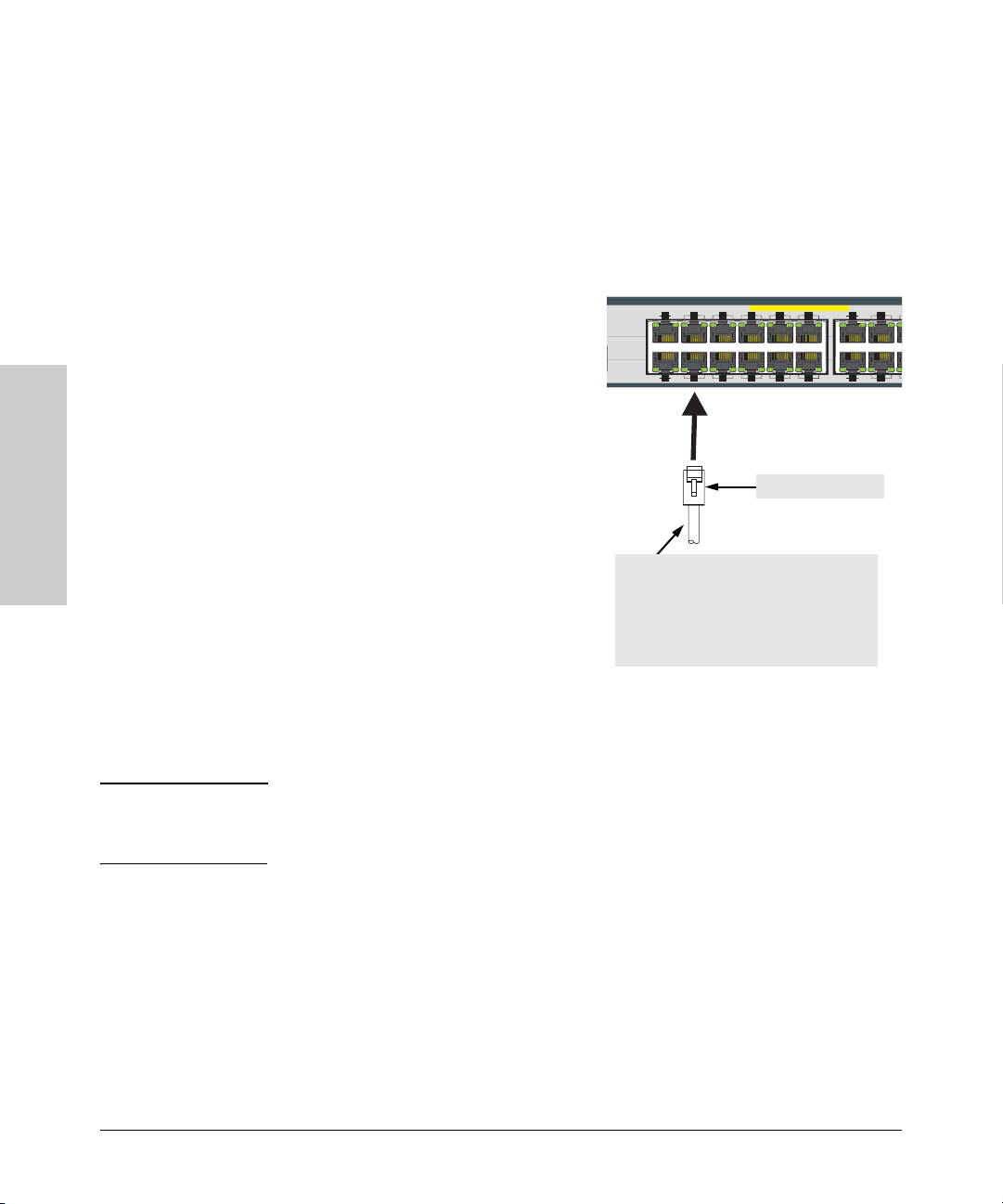
To connect:
Push the RJ-45 plug into the RJ-45 jack
ff=10Mbps
lash= 100Mbps
n=1000Mbps
Link
Mode
PoE-Integrated 10/100/1 000Base- T Ports (1 - 2 4T) — Portsare IEEE A ut o MDI/
1197531
until the tab on the plug clicks into
place. When power is on for the switch
and for the connected device, the Link
Link
Mode
12108642
LED for the port should light to confirm
a powered-on device (for example, an
end node) is at the other end of the
cable.
RJ-45 connector
If the Link LED does not go on when the
network cable is connected to the port,
see “Diagnosing with the LEDs” on
page 5-4, in chapter 5, “Trouble-
shooting”.
To disconnect:
Press the small tab on the plug and pull
the plug out of the jack.
Unshielded twisted-pair cable:
• Category 3, 4, or 5 for 10 Mbps ports
• Category 5 or better for 100 Mbps ports
• Category 5e or better for 1000 Mbps ports
Maximum distance: 100 meters
Figure 2-9. Connecting an RJ-45.
Connecting Cables to mini-GBICs
Note Each of the four mini-GBIC slots is shared with the associated 10/100/
1000Base-T RJ-45 port. If a mini-GBIC is installed in a slot, the associated RJ45 port is disabled.
Link
Link Mode
14 16
Mode
1513
If you have any mini-GBICs installed in the switch, the type of network
connections you will need to use depends on the type of mini-GBICs you have
installed. See the table on page 2-6, and appendix B, “Switch Ports”, for the
mini-GBIC cabling information.
For mini-GBICs ports, and in general for all the switch ports, when a network
cable from an active network device is connected to the port, the port LED
for that port should go on. If the port LED does not go on when the network
cable is connected to the port, see “Diagnosing with the LEDs” on page 5-4
in chapter 5, “Troubleshooting”.
2-16
Page 39
Connecting a fiber cable
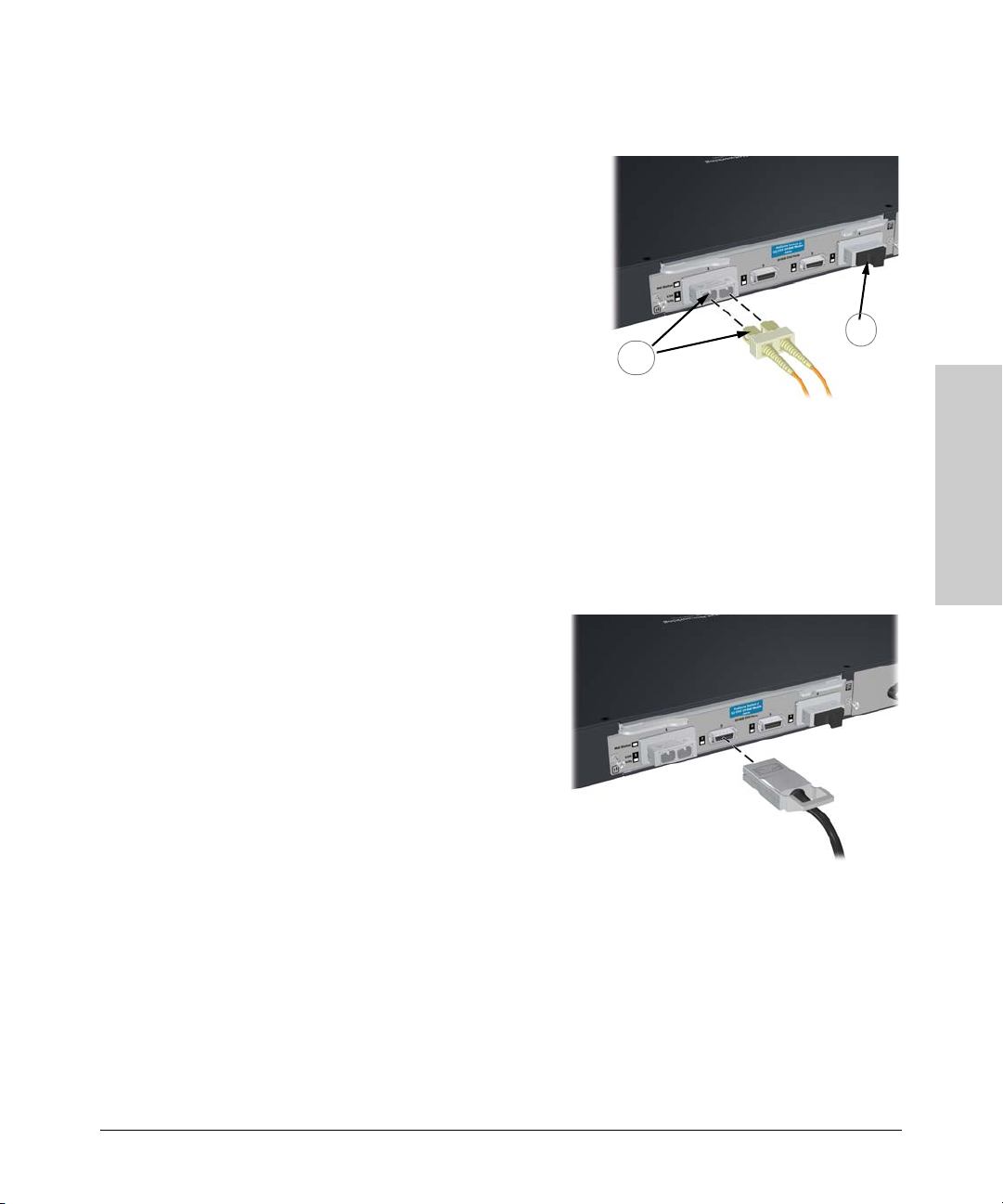
To connect:
1. Remove the dust covers from
the cable connectors and the
port.
2. Aligning the notches on the
cable connectors with the slots
of the port, press the cable
connector into the port until it
snaps into place.
Installing the Switch
Installation Procedures
1
2
If the Link LED does not go on
when the network cable is
connected to the port, see
“Diagnosing with the LEDs” on page 5-4, in chapter 5, “Troubleshooting”.
To disconnect:
Pull the cable connector straight out.
Figure 2-10. Connecting fiber optic cable.
Connecting a copper cable
To connect:
1. Push the copper cable
connector into the copper port.
Ensure the locking device locks
the cable connector into place.
To disconnect:
Pull the cable connector straight
out.
When a network cable from an
active network device is connected
to the port, the port LED for that
port should go on. If the port LED
does not go on when the network
cable is connected to the port, see “Diagnosing with the LEDs” on page 5-4 in
chapter 5, “Troubleshooting”.
Figure 2-11. Connecting copper cable.
Installing the Switch
2-17
Page 40

Installing the Switch
Installing the Switch
Installation Procedures
9. (Optional) Connect a 620 Redundant Power Supply to the switch
The ProCurve 620 Redundant and External Power Supply, (J8696A), hereafter
referred to as the 620 RPS/EPS, is an accessory product for the Series 3500yl
and 6200yl switches and specific other ProCurve switches. The 620 RPS/EPS
provides two types of power to the switches:
■ Redundant power to two switches, to back up the internal switch power
supply in case of AC power loss, or a fault condition. Should the internal
switch power supply fail, power will be supplied from the 620 RPS/EPS.
■ External Power-over-Ethernet (PoE) power to up to two switch products.
The 620 RPS/EPS can supply 398 watts of PoE power to the switch if the
internal PoE power supply should fail. For the Switch 3500yl-48G-PWR
the external PoE power is additional power made available to the switch’s
ports. For further information regarding the 620 RPS/EPS PoE capabilities, see the ProCurve Power over Ethernet (PoE) for zl and yl Products
Planning and Implementation Guide and the ProCurve 620 Redundant
and External Power Supply Installation and Getting Started Guide,
which are on the ProCurve Web site at www.procurve.com.
See page 5-1 for details.
The 620 RPS/EPS is an unmanaged power supply that only provides information by way of LEDs.
2-18
RPS/EPS Operation
The RPS/EPS monitors the power signal from the switch by detecting that the
RPS/EPS is connected to a valid switch with an RPS/EPS cable. When the
power from the switch is no longer detected, the RPS/EPS will turn on and
provide power to the switch within 1 millisecond.
The RPS/EPS supports hot plugging of the RPS cable only, Hot disconnect of
the EPS (PoE power) cable is not supported, and could cause loss of power
to the switch. The EPS cable can be connected at any time. The RPS/EPS unit
must be powered down in order to unplug the EPS (PoE power) cable, if power
is flowing.
Page 41
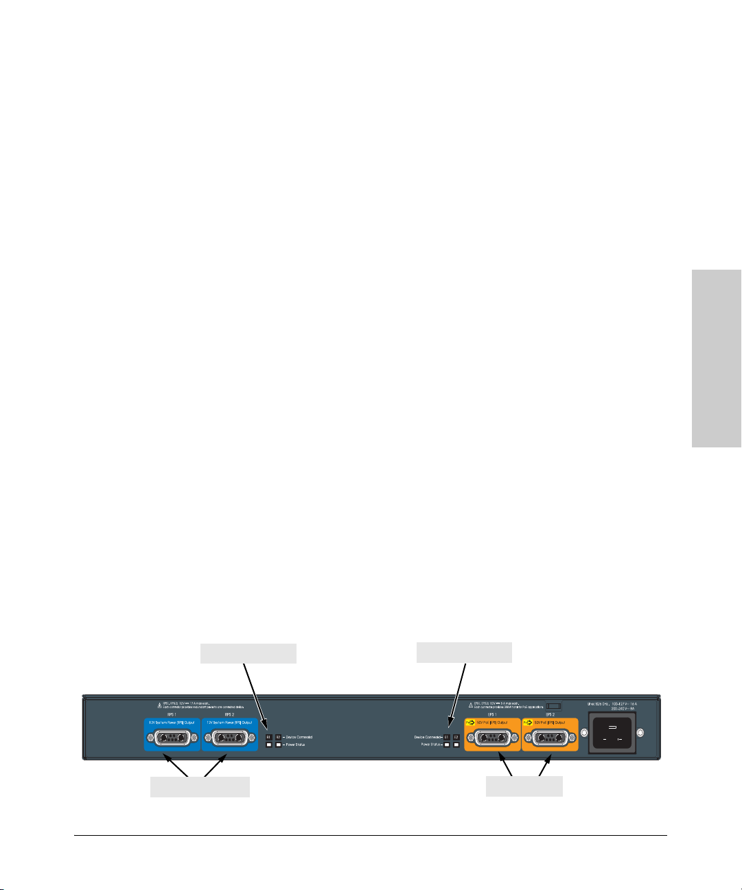
Installing the Switch
Installation Procedures
Operating Characteristics of the 620 RPS/EPS (J8696A)
The 620 RPS/EPS has two RPS ports, each of which can provide redundant
+12V power to a connected switch. If a switch with no AC power is connected
to an operating 620 RPS/EPS, it will not receive power. The switch must first
be powered on, then connected to the 620 RPS/EPS.
The 620 RPS/EPS also has two EPS Ports. The 620 RPS/EPS can provide a
maximum of 398 watts of PoE power to each of the two EPS ports. It is
important to understand the PoE power requirements of the 3500yl-PWR
Series switches because if the PoE power is not planned and implemented
correctly the end devices connected to the switch ports may not receive power
if an internal switch PoE power supply should fail. For further information
regarding the 620 RPS/EPS PoE capabilities, see the ProCurve Power over
Ethernet (PoE) for zl and yl Products Planning and Implementation Guide
and the ProCurve 620 Redundant and External Power Supply Installation
and Getting Started Guide, which is on the ProCurve Web site. See page 5-1
for details.
For redundant AC power, connect the 620 RPS/EPS to the switch using one
of the supplied RPS cables. For redundant or additional PoE power, connect
the 620 RPS/EPS to the switch using one of the supplied EPS cables. The RPS
and EPS cables are 2.00 meters (6.56 feet) in length. These cables are identical.
If accidentally cross connected, nothing will happen. No power will flow until
properly connected.
Installing the Switch
620 RPS/EPS LEDs
The 620 RPS/EPS LEDs are duplicated on the front and back of the device.
The following graphic shows an example of the back of the 620 EPS/RPS.
There are two dual colored (green/orange) LEDs for each RPS and EPS port:
■ Device Connected
■ Power Status
RPS port LEDs
RPS ports
Figure 2-12. The back of a 620 RPS/EPS.
EPS port LEDs
EPS ports
2-19
Page 42

Installing the Switch
Installation Procedures
LED State Meaning
Installing the Switch
Power
(green)
Fault
(orange)
On The unit is powered on.
Off The unit is NOT powered on.
Off The normal state; indicates that there are no fault conditions on the unit.
Blink
orange
A fault has occurred on the unit, one of the ports, or the fan. The Status LED for the
1,3
component with the fault will blink simultaneously.
On On briefly after the unit is powered on or reset, at the beginning of unit self test. If
this LED is on for a prolonged time, the unit has encountered a fatal hardware
failure, or has failed its self test. See chapter 3, “Troubleshooting” for more
information.
Temp Status
On The temperature of the unit is within specification.
(green and orange)
Blink
orange
One of these conditions exists:
2
• A cooling fan has failed. The unit Fault LED and Fan Status LED will be blinking
simultaneously.
• There is an over temperature condition in the unit. The unit Fault LED is off.
Fan Status
(green and orange)
On The cooling fans are operating normally.
Blink
orange
A cooling fan has failed. The unit Fault LED will be blinking simultaneously.
1
Port Status (also on back panel of the 620 RPS/EPS)
Device Connected
On There is a valid connection to a device.
(green – over-laid
with the port
Off There is no valid device connected to the port.
number)
Power Status
On The unit is supplying power to a connected device.
(green and orange)
Off One of these conditions exists:
• There is no connected device.
• A connected RPS device does not require power.
• A connected EPS device has not successfully communicated for EPS power.
Blink
orange
One of these conditions exists:
1
• On the 620 RPS/EPS, RPS power is not available to the connected device
because there is a hardware or power supply failure in the 620 RPS/EPS unit.
• When the LED is blinking simultaneously with the Fault LED, there is a fault
condition on the port.
1
The blinking behavior is an on/off cycle once every 1.6 seconds, approximately.
2
The blinking behavior is an on/off cycle once every 0.8 seconds, approximately.
3
Specific fault conditions can be viewed by checking switch log files.
2-20
Page 43

Installing the Switch
Installation Procedures
620 RPS/EPS Connectivity
This section shows some recommended connection topologies using the 620
RPS/EPS. The 620 RPS/EPS can provide backup power support for up to two
ProCurve switches. In the illustration below, two ProCurve Switch 3500yl24G-PWR units are connected to the RPS ports on a 620 RPS/EPS.
Figure 2-13. Connecting RPS to 2, 24 port switches.
The 620 RPS/EPS is designed to provide primary or backup power to up to
two ProCurve PoE switches. In the following illustration, two ProCurve
Switch 3500yl-24G-PWR units are being supplied with external PoE power
from an 620 RPS/EPS. The switches provide PoE power to Ethernet devices
connected to their ports.
Installing the Switch
Figure 2-14. Connecting EPS to 2, 24 port switches.
2-21
Page 44

Installing the Switch
Installing the Switch
Installation Procedures
10. (Optional) Connect a Console to the Switch
The switch has a full-featured, easy to use console interface for performing
switch management tasks including the following:
■ monitor switch and port status and observe network activity statistics
■ modify the switch’s configuration to optimize switch performance,
enhance network traffic control, and improve network security
■ read the event log and access diagnostic tools to help in troubleshooting
■ download new software to the switch
■ add passwords to control access to the switch from the console, web
browser interface, and network management stations
The console can be accessed through these methods:
■ Out-of-band: The switch comes with a serial cable for connecting a PC
or VT-100 terminal, to be used as a console, directly to the switch.
■ In-Band: Access the console using Telnet from a PC or UNIX station on
the network, and a VT-100 terminal emulator. This method requires that
you first configure the switch with an IP address and subnet mask by using
either out-of-band console access or through DHCP/Bootp. For more
information on IP addressing and on starting a Telnet session, see
chapter 3, “Getting Started With Switch Configuration”, and the Man-
agement and Configuration Guide, which is on the ProCurve Web site,
www.procurve.com. (See page 5-1 for details.)
2-22
The Switch can simultaneously support one out-of-band console session
through the Console Port and one in-band Telnet console session.
Terminal Configuration
To connect a console to the switch, configure the PC terminal emulator as a
DEC VT-100 (ANSI) terminal or use a VT-100 terminal, and configure either
one to operate with these settings:
■ any baud rate from 1200 to 115200 (the switch senses the speed)
■ 8 data bits, 1 stop bit, no parity, and flow control set to Xon/Xoff
■ for the Windows Terminal program, also disable (uncheck) the “Use
Function, Arrow, and C
■ for the Hilgraeve HyperTerminal program, select the “Terminal keys”
option for the “Function, Arrow, and C
If you want to operate the console using a different configuration, make sure
you change the settings on both the terminal and on the switch so they are
compatible. Change the switch settings first, save your changes, then change
the terminal settings, then reboot the switch and reestablish the console
session.
trl Keys for Windows” option
trl Keys act as” parameter
Page 45

Installing the Switch
Installation Procedures
Direct Console Access
To connect a console to the
switch, follow these steps:
1. Connect the PC or
terminal to the switch’s
Console Port using the
Console port
Power
Fault
Locator
console cable included
with the Switch. (If your
PC or terminal has a 25-pin
serial connector, first
Console cable supplied
with the switch
attach a 9-pin to 25-pin
straight-through adapter
at one end of the console
cable.)
2. Turn on the terminal or
PC running a terminal
emulator program, or
a VT-100 terminal
PC’s power and, if using a
PC, start the PC terminal
Figure 2-15. Connecting a console cable.
program.
3. Press
[Enter] two or three
times and you will see the
copyright page and the
This picture demonstrates the Switch
3500yl-24G. Remember the console port
on the Switch 3500yl-48G is in back.
message “Press any key to
continue”. Press a key, and you will then see the switch console command
(CLI) prompt, for example:
ProCurve
Switch 3500y l
J8692A
Status
PoE
Mode
Tmp
Fan
Test
Reset
Status of the Back
Mdl RPSEPS
PoE
Act
FDx
LED
Spd
*
PoE
Usr
Clear
Spdmode: off = 10Mbps
*
flash= 100Mbps
on= 1000Mbps
Auxiliar y Port
Console
Link
Mode
531
Link
Mode
642
Installing the Switch
ProCurve Switch 3500yl-24G#
If you want to continue with console management of the switch at this time,
see chapter 3, “Getting Started With Switch Configuration” for some basic
configuration steps. For more detailed information, refer to the Management
and Configuration Guide, which is on the ProCurve Web site,
www.procurve.com. (See page 5-1 for details.)
2-23
Page 46

Installing the Switch
Sample Network Topologies
Sample Network Topologies
This section shows a few sample network topologies in which the switch is
implemented. For more topology information, see the ProCurve network
products Web site,
Server with Gigabit
Ethernet NIC
Statusof the Back
ProCurve
Mdl RPSEPS
Switch 3500y l
J8692A
PoE
Act
Status
Power
PoE
FDx
LED
Mode
Spd
Tmp
*
Fault
Fan
PoE
Test
Usr
Locator
Console
Reset
Clear
www.procurve.com.
Link
Mode
Link
Mode
PoE-Integrated10/100/1 000Base-T P orts (1 - 24T) — Ports are IEEE A uto MDI/MDI- X
Spdmode: off=10Mbps
*
Auxiliary Por t
flash=100Mbps
on=1000Mbps
ProCurve Switch 3500yl-24G
Dual-PersonalityPorts: 1 0/1 00/1 000-T (T) o r Mini-GBIC (M)
18 20
Link Mode
M 23M
23T21T
21
19171513
22T 24T
Link Mode
22M 24M
oreachP ort
Useonlyone (T or M) f
!
Link
Mode
1197531
Link Mode
14 16
12108642
Installing the Switch
Fast Ethernet cable
Gigabit Ethernet cable
PCs, local servers, and
peripherals
Figure 2-16. As a Desktop Switch.
The Switch is designed to be used primarily as a desktop switch to which end
nodes, printers and other peripherals, and servers are directly connected, as
shown in the above illustration. Notice that the end node devices are
connected to the switch by straight-through or crossover twisted-pair cables.
Either cable type can be used because of the “IEEE Auto MDI/MDI-X” features
on the Switch.
2-24
Page 47

ProCurve 620
RPS/EPS
ProCurve Switch
3500yl-24G
Installing the Switch
Sample Network Topologies
Server
Installing the Switch
Twisted-pair
straight-through or
crossover cables
IP Telephones
Wireless Access
Point
PCs and peripherals
Figure 2-17. As a Desktop Switch Implementing PoE.
This illustration is the same as figure 2-16, except now the switch is configured
to supply PoE power to end devices such as IP telephones and wireless access
points (WAPs).
As shown in the above illustration the IP telephones can be connected in line,
that is, between the switch and the end device, in this case a PC. The IP
telephones in this illustration have two ports, one in and one out. Therefore
the phone receives voice and power from the switch and the PC can send and
receive data through the phone to the switch.
The end node devices are connected to the switch by straight-through or
crossover twisted-pair cables. Either cable type can be used because of the
“IEEE Auto MDI/MDI-X” features on the Switch.
2-25
Page 48
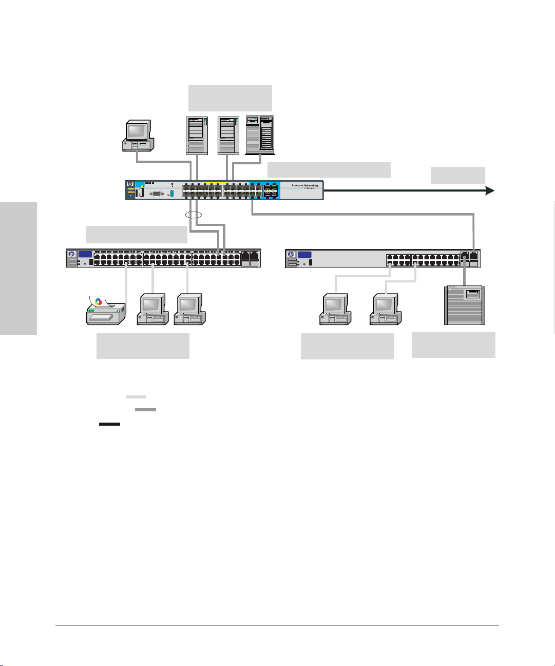
Installing the Switch
Sample Network Topologies
Server with Gigabit
Ethernet NIC
Installing the Switch
Fast Ethernet Switch
hpprocur ve
switch2650
J4899A
Act
Power
FDx
Max
Fault
PCs, local servers, and
peripherals
LEGEND:
Fast Ethernet cable
Gigabit Ethernet cable
Fiber cable
Link
Mode
Link
Mode
PoE-Integrated10/100/1 000Base-T P orts (1 - 24T) — Ports are IEEE A uto MDI/MDI- X
Link
Mode
1197531
Link Mode
14 16
12108642
Statusof the Back
ProCurve
Spdmode: off=10Mbps
Mdl RPSEPS
*
Switch 3500yl
J8692A
PoE
Act
Status
Power
PoE
FDx
LED
Mode
Spd
Tmp
Fault
Fan
PoE
Test
Usr
Locator
Reset
Clear
flash=100Mbps
on=1000Mbps
*
Auxiliary Port
Console
Figure 2-18. As a Segment Switch.
18 20
Dual-PersonalityPorts: 1 0/1 00/1 000-T (T) o r Mini-GBIC (M)
19171513
22T 24T
ProCurve Switch 3500yl-24G
ort
Link Mode
M 23M
23T21T
21
P
h
ac
e
r
o
)f
M
r
o
(T
ne
o
nly
o
se
U
!
Link Mode
22M 24M
hpp rocur ve
swit ch 2650
J4899A
Act
Power
FDx
Max
Fault
PCs, local servers, and
peripherals
To Backbone
Server with Gigabit
Ethernet NIC
2-26
The Switch also works well as a segment switch. That is, with its high
performance, it can be used for interconnecting network segments—simply
connect the network hubs that form those segments to the switch, or you can
also connect other switches.
In the illustration above, two “Fast” Ethernet hubs with PCs, printers, and local
servers attached, are both connected to a Switch. The devices attached to the
two hubs can now communicate with each other through the switch. They can
also all communicate with the server that is connected to a 1000Base-T port
on the switch.
Page 49
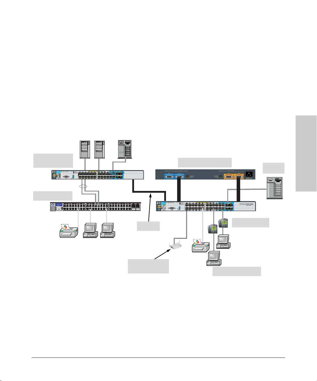
Installing the Switch
Sample Network Topologies
Because the Switch has the “IEEE Auto MDI/MDI-X” features, the connections
between the switch and the hubs, and between the switch and end nodes or
servers can be through category 5 straight-through or crossover twisted-pair
cable. Category 3 or 4 cable can also be used if the connection is 10 Mbps only.
In all cases, the device ports must be configured to auto negotiate the link
characteristics for this feature to work.
The switch, in turn, can be connected to a network backbone through fiberoptic cabling connected to a Gigabit-SX, -LX, or -LH mini-GBIC installed in the
switch. Now, all the devices on these network segments can access other
network resources that are connected elsewhere on the network backbone.
Installing the Switch
ProCurve Switch
3500yl-24G
Non-PoE Switch
10-GbE
Wireless Access
Point
ProCurve 620 RPS/EPS
IP Telephones
PCs and peripherals
Server
Figure 2-19. As a Segment Switch Implementing PoE.
As shown in figure 2-19, the IP telephones have been inserted in between the
Switch 3500yl-PWR and the PCs, and a WAP has been connected to the Switch
3500yl-PWR. Both the telephones and WAP will receive PoE power from the
Switch 3500yl-PWR. Only devices directly connected to the PWR switches can
receive PoE power. Devices connected to a non-PWR switch cannot receive
PoE power.
2-27
Page 50
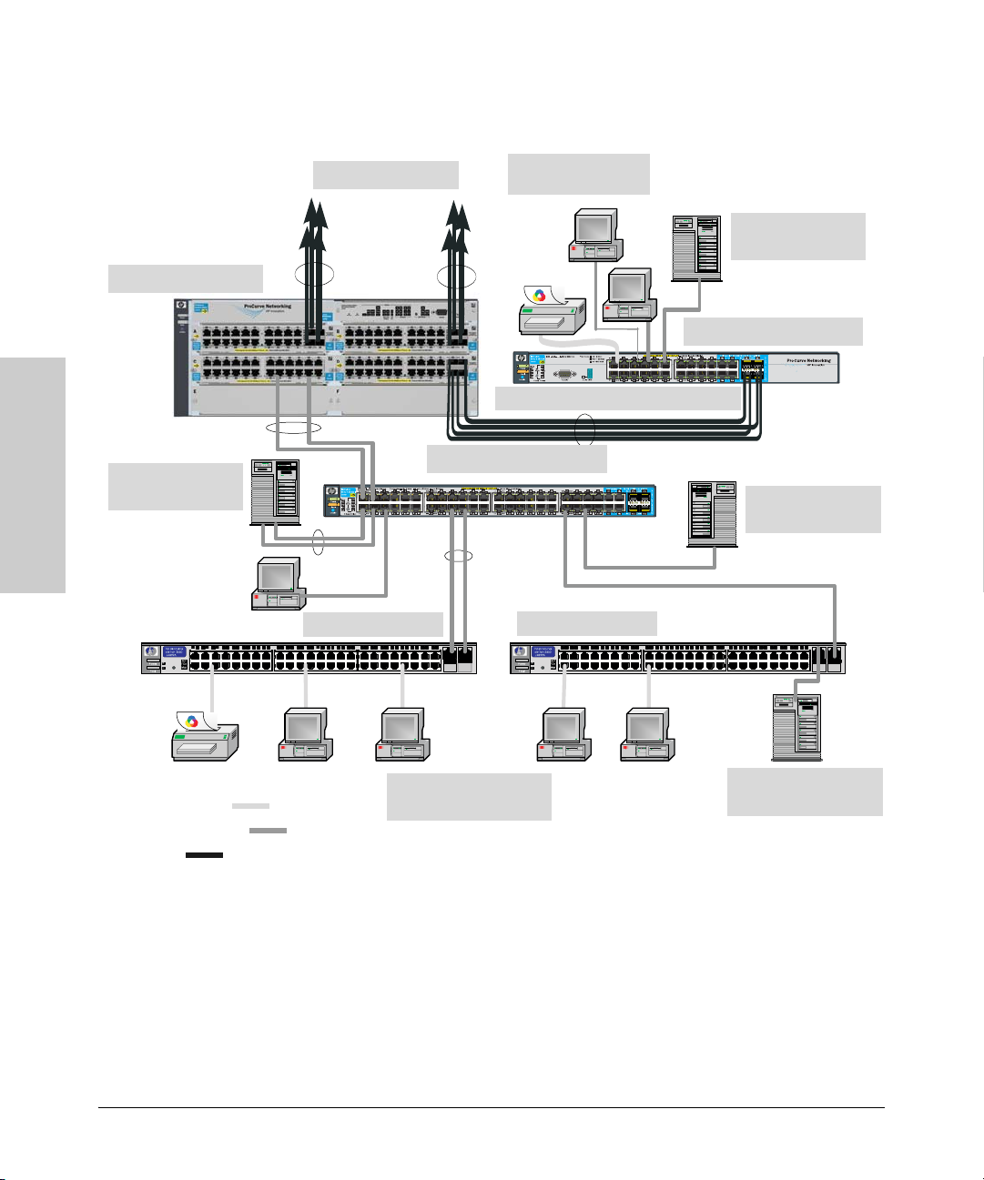
Installing the Switch
Sample Network Topologies
Installing the Switch
ProCurve Switch 5406zl
Servers with Gigabit
Ethernet NIC
To IT or Data Center
Fast Ethernet Switch
PCs, local servers, and
peripherals
Servers with Gigabit
Ethernet NIC
ProCurve Switch 3500yl-24G
Gigabit link (use fiber if over 100 meters)
ProCurve Switch 3500yl-48G
Servers with Gigabit
Ethernet NIC
Fast Ethernet Switch
LEGEND:
Fast Ethernet cable
Gigabit Ethernet cable
Fiber cable
2-28
PCs, local servers, and
peripherals
Servers with Gigabit
Ethernet NIC
Figure 2-20. Connecting to a Backbone Switch.
The simpler desktop and segment networks shown in the previous two
examples can easily be combined and expanded. For example, you could use
an ProCurve Switch 5304xl to interconnect each of your smaller switched
workgroups to form a larger switched network. All the devices in this network
can communicate with each other. With a Gigabit-SX Module, for example, in
the Switch 5304xl, the entire switched topology could be connected to a
campus backbone, as shown in figure 2-3.
Page 51
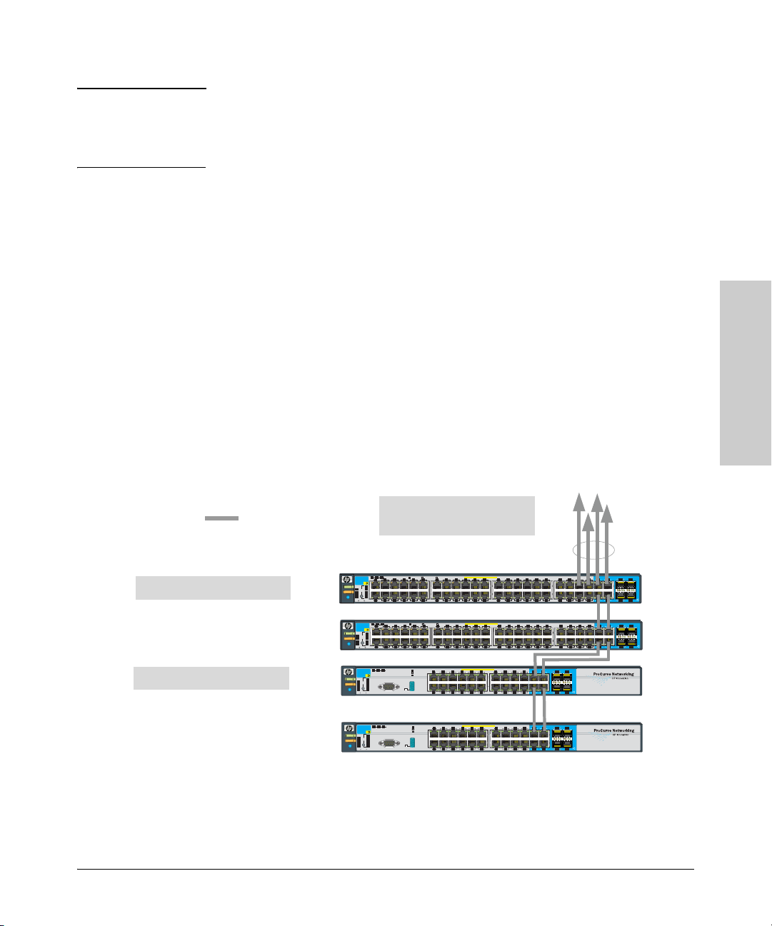
Installing the Switch
Sample Network Topologies
Note In the Backbone Switch illustration, the 1000 Mbps fiber-optic connection
between the Switch 3500yl-24G and the Switch 5304xl is by way of a GigabitSX mini-GBIC installed in the Switch 3500yl-24G and connected to a GigabitSX Module in the Switch 5304xl.
Stacking the Switch
The Series 3500yl Switches can be connected together, through standard
network connections, and managed through a single IP address. Up to 16
switches can be connected together in such a “virtual stack”.
LEGEND:
Gigabit Ethernet cable
ProCurve Switch 3500yl-48G
ProCurve Switch 3500yl-24G
Through switch console commands, you can identify one of the switches as
the “Commander” and give that switch an IP address. Up to 15 other switches
in the network can then easily be configured as Members of the stack and
managed through the Commander’s IP address. The management includes
Telnet access and web browser interface access to the Commander and to
each Member switch through the Commander.
For more information on stacking Switches, please see the Management and
Configuration Guide, which is on the ProCurve Web site at
www.procurve.com. See page 5-1 for details.
To Gigabit-Ethernet Backbone
(Use fiber if over 100 meters)
119753
1210
Link
Link
Link
Link
Link
Mode
Link
Mode
Mode
Mode
1614
Mode
Mode
1614
PoE-Integrated10/100/1 000Base-T P orts (1 - 48T) — Ports are IEEE A uto MDI/MDI- X
Link
Mode
232119171513
Link
Mode
24222018
PoE-Integrated10/100/1 000Base-T P orts (1 - 48T) — Ports are IEEE A uto MDI/MDI- X
Link
Mode
232119171513
Link
Mode
24222018
PoE-Integrated10/100/1 000Base-T P orts (1 - 24T) — Ports are IEEE A uto MDI/MDI- X
Link
Mode
1197531
Link Mode
14 16
12108642
18 20
Dual-PersonalityPorts: 1 0/1 00/1 000-T (T) o r Mini-GBIC (M)
19171513
23T21T
22T 24T
353331292725
363432302826
353331292725
363432302826
Link Mode
Link Mode
Spdmode: off=10Mbps, flash=100Mbps, on = 1000Mbps
Statusof the Back
Mdl RPSEPS
*
ProCurve
Link
Mode
1
Switch 3500y l
J8692A
PoE
Act
Status
Power
PoE
FDx
LED
Mode
Tmp
Spd
*
Fault
Fan
PoE
Test
Usr
Locator
Link
Mode
Reset
Clear
Mdl RPSEPS
ProCurve
Link
Mode
1
Switch 3500y l
J8692A
PoE
Act
Status
Power
PoE
FDx
LED
Mode
Tmp
Spd
*
Fault
Fan
PoE
Test
Usr
Locator
Link
Mode
Reset
Clear
ProCurve
Mdl RPSEPS
Switch 3500y l
J8692A
PoE
Act
Status
Power
PoE
FDx
LED
Mode
Tmp
Spd
*
Fault
Fan
PoE
Test
Usr
Locator
Reset
Clear
8642
Spdmode: off=10Mbps, flash=100Mbps, on = 1000Mbps
Statusof the Back
*
8642
Statusof the Back
Spdmode: off=10Mbps
*
Console
119753
1210
flash=100Mbps
on=1000Mbps
Auxiliary Por t
Link
Link
Link
Link
21
M 23M
22M 24M
37
38 40
37
38 40
Dual-PersonalityPorts: 1 0/1 00/1 000-T (T) o r Mini-GBIC (M)
42 44
42 44
Port
oreach
onlyone(T or M) f
Use
!
434139
47T45T
46T 48T
Dual-PersonalityPorts: 1 0/1 00/1 000-T (T) o r Mini-GBIC (M)
434139
46T 48T
Link Mode
45
M 47M
Port
oreach
onlyone(T or M) f
Use
!
Link Mode
46M 48M
Link Mode
45
M 47M
47T45T
oreachP ort
)f
orM
one(T
Useonly
!
Link Mode
46M 48M
Mode
Mode
Mode
Mode
Installing the Switch
Statusof the Back
ProCurve
Switch 3500y l
J8692A
Status
Power
PoE
Tmp
Fault
Fan
Test
Locator
Spdmode: off=10Mbps
Mdl RPSEPS
*
flash=100Mbps
PoE
Act
FDx
LED
Mode
Spd
*
PoE
Usr
Reset
Clear
on=1000Mbps
Auxiliary Por t
Console
Link
Mode
Link
Mode
PoE-Integrated10/100/1 000Base-T P orts (1 - 24T) — Ports are IEEE A uto MDI/MDI- X
Figure 2-21. Stacking switches using gigabit.
Dual-PersonalityPorts: 1 0/1 00/1 000-T (T) o r Mini-GBIC (M)
Link
Mode
1197531
Link Mode
14 16
12108642
Link Mode
21
19171513
M 23M
23T21T
Port
oreach
onlyone(T or M) f
Use
!
Link Mode
22M 24M
18 20
22T 24T
2-29
Page 52
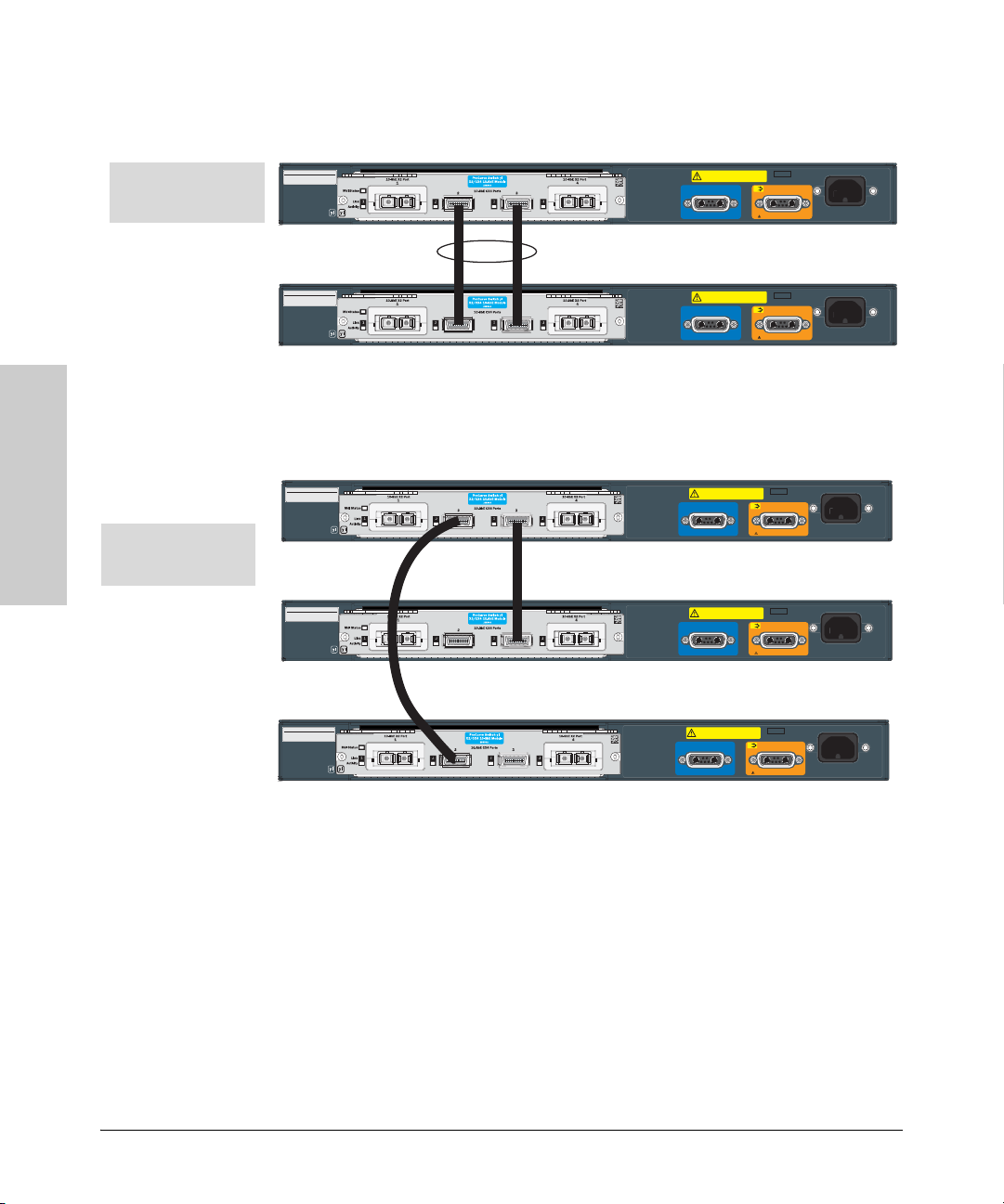
Installing the Switch
Sample Network Topologies
Installing the Switch
Stack of two 3500yl-24G
switches using CX4
cables trunked.
Stack of three 3500yl-
24G switches using CX4
only and not trunked.
SerialNo. SG12345678
SystemMAC Address
00-01-E7-12-34-56
SerialNo. SG12345678
SystemMAC Address
00-01-E7-12-34-56
10-GbEX2 Port
1 4
MdlS tatus
Link
1
Activity
yl
10-GbEX2 Port
1 4
MdlS tatus
Link
1
Activity
yl
ProCurve Switc h yl
X2/CX4 10-GbE Module
J8694A
10-GbECX4 Ports
23
3
42
ProCurve Switc h yl
X2/CX4 10-GbE Module
J8694A
10-GbECX4 Ports
23
3
42
10-GbEX2 Port
10-GbEX2 Port
Figure 2-22. Stacking two switches using 10-GbE CX4.
SerialNo. SG12345678
SystemMAC Address
00-01-E7-12-34-56
SerialNo. SG12345678
SystemMAC Address
00-01-E7-12-34-56
10-GbEX2 Port
1 4
MdlS tatus
Link
1
Activity
yl
10-GbEX2 Port
1 4
MdlS tatus
Link
1
Activity
yl
ProCurve Switc h yl
X2/CX4 10-GbE Module
J8694A
10-GbECX4 Ports
23
3
42
ProCurve Switc h yl
X2/CX4 10-GbE Module
J8694A
10-GbECX4 Ports
23
3
42
10-GbEX2 Port
10-GbEX2 Port
CAUTION: MULTIPLE PO WER SOUR CES
Disconnectall AC powercords,and EPS and RPS
cablesto completelyremovepowerfromthe unit.
CAUTION: MULTIPLE PO WER SOUR CES
Disconnectall AC powercords,and EPS and RPS
cablesto completelyremovepowerfromthe unit.
CAUTION: MULTIPLE PO WER SOUR CES
Disconnectall AC powercords,and EPS and RPS
cablesto completelyremovepowerfromthe unit.
CAUTION: MULTIPLE PO WER SOUR CES
Disconnectall AC powercords,and EPS and RPS
cablesto completelyremovepowerfromthe unit.
PoE
ConnectProCurve620 EPS only
PoE
ConnectProCurve620 EPS only
PoE
ConnectProCurve620 EPS only
PoE
ConnectProCurve620 EPS only
12VSys tem Power (RPS) Input 50VP oE (EPS) Input
12VSys tem Power (RPS) Input 50VP oE (EPS) Input
12VSys tem Power (RPS) Input 50VPoE (EPS) Input
12VSys tem Power (RPS) Input 50VPoE (EPS) Input
Line:50/60 Hz.
100-127V~ 10A
200-240V~ 5 A
Line:50/60 Hz.
100-127V~ 10A
200-240V~ 5 A
Line:50/60 Hz.
100-127V~ 10A
200-240V~ 5 A
Line:50/60 Hz.
100-127V~ 10A
200-240V~ 5 A
2-30
SerialNo. SG12345678
SystemMAC Address
00-01-E7-12-34-56
10-GbEX2 Port
1 4
MdlS tatus
Link
1
Activity
yl
ProCurve Switc h yl
X2/CX4 10-GbE Module
J8694A
10-GbECX4 Ports
23
3
42
10-GbEX2 Port
12VSys tem Power (RPS) Input 50VPoE (EPS) Input
Figure 2-23. Stacking three switches using 10-GbE CX4.
CAUTION: MULTIPLE PO WER SOUR CES
Disconnectall AC powercords,and EPS and RPS
cablesto completelyremovepowerfromthe unit.
PoE
ConnectProCurve620 EPS only
Line:50/60 Hz.
100-127V~10A
200-240V~ 5 A
Page 53

Installing the Switch
3
A
A
A3
Sample Network Topologies
Stack of three 3500yl-24G
switches using CX4 and
fiber cables trunked.
SerialNo. SG12345678
SystemMAC Address
00-01-E7-12-34-56
SerialNo. SG12345678
SystemMAC Address
00-01-E7-12-34-56
SerialNo. SG12345678
SystemMAC Address
00-01-E7-12-34-56
10-GbEX2 Port
1 4
MdlS tatus
Link
1
Activity
yl
10-GbEX2 Port
1 4
MdlS tatus
Link
1
Activity
yl
10-GbEX2 Port
1 4
MdlS tatus
Link
1
Activity
yl
ProCurve Switc h yl
X2/CX4 10-GbE Module
J8694A
10-GbECX4 Ports
23
3
42
ProCurve Switc h yl
X2/CX4 10-GbE Module
J8694A
10-GbECX4 Ports
23
3
42
ProCurve Switc h yl
X2/CX4 10-GbE Module
J8694A
10-GbECX4 Ports
23
3
42
10-GbEX2 Port
10-GbEX2 Port
10-GbEX2 Port
CAUTION: MULTIPLE PO WER SOUR CES
Disconnectall AC powercords,and EPS and RPS
cablesto completelyremovepowerfromthe unit.
CAUTION: MULTIPLE PO WER SOUR CES
Disconnectall AC powercords,and EPS and RPS
cablesto completelyremovepowerfromthe unit.
CAUTION: MULTIPLE PO WER SOUR CES
Disconnectall AC powercords,and EPS and RPS
cablesto completelyremovepowerfromthe unit.
PoE
ConnectProCurve620 EPS only
PoE
ConnectProCurve620 EPS only
PoE
ConnectProCurve620 EPS only
12VSys tem Power (RPS) Input 50VPoE (EPS) Input
12VSys tem Power (RPS) Input 50VPoE (EPS) Input
12VSys tem Power (RPS) Input 50VPoE (EPS) Input
Line:50/60 Hz.
100-127V~10A
200-240V~ 5 A
Line:50/60 Hz.
100-127V~10A
200-240V~ 5 A
Line:50/60 Hz.
100-127V~ 10A
200-240V~ 5 A
Figure 2-24. Stacking three switches using CX4 and fiber.
Optimizing the 10-GbE Port Configuration
The 10-GbE ports on the ProCurve Switch 3500yl and 6200yl series are
designed to deliver full 10 Gbps wire-speed to each port, where either one or
two ports are in a linked state with another device. When three or four 10-GbE
ports are in a linked state, the 10-GbE ports support an aggregate bandwidth
of 28.8 Gbps across the linked ports.
Installing the Switch
As illustrated in the figure below, internally, there are two 14.4-Gbps channels
between each of the 4 10-GbE ports and the switch fabric.
A1
(X2)
4
1
4 2
(X2)
14.4 Gbps
14.4 Gbps
Channel
Channel
10-GbE Module Port s
(CX4)
10-GbE Ports
Swit ch
2
(CX4)
14.4 Gbps
14.4 Gbps
Channel
Channe l
Figure 2-25. 10-GbE port architecture showing ports grouped by 14.4 Gbps channel.
2-31
Page 54
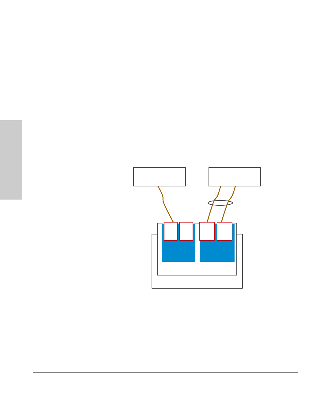
Installing the Switch
n
t
A
A
Sample Network Topologies
When any two 10-GbE ports are in a linked state, each port automatically
operates on its own channel, which guarantees 10 Gbps of bandwidth for each
port. However, when more than two ports are in a linked state, ports A1 and
A4 are statically mapped to share one 14.4 Gbps channel, while ports A2 and
A3 are statically mapped to share the other 14.4 Gbps channel.
To summarize:
■ If only one port in a given channel is in a linked state, then that port
operates at wire speed and the other port uses no bandwidth.
■ If both ports in a given channel are in a linked state, then the 14.4 Gbps of
bandwidth is balanced fairly between the two ports.
For example, in an application where three ports are needed and it is important to ensure that port 1 always has a full 10 Gbps available, the connection
choices shown in the next figure would be used.
Installing the Switch
5400zlSwitch
5400zlSwitch
5400zlSwitch
with 10-GbE Module
with 10-GbE Module
with 10-GbE Module
Port A1 is guaranteed 10
Gbps because it does
not need to share the
channel with port A4
Port 4 is
Port 4 is
not used
not used
1
4 2
1
4
(X2)
(X2)
14.4 Gbps
Channel
14.4 Gbps
-
GbE Module Ports
Channel
10-GbE Ports
Switch
A2
(CX2)
5400zlSwitch
5400zlSwitch
5400zlSwitch
with 10
with 10
with 10
3
A3
(CX2)
14.4 Gbps
Channel
14.4 Gbps
Channel
Figure 2-26. Guaranteeing 10 Gbps on a specific port.
-
-
-
GbE Module
GbE Module
GbE Module
Ports A2 and A3 share this cha
in a trunked link, which fairly
in a trunked link, which fairly
balances the 14.4 Gbps
balances the 14.4 Gbps
bandwidth between the two por
2-32
Page 55

Getting Started With Switch Configuration
This chapter is a guide for using the console Switch Setup screen to quickly
assign an IP (Internet Protocol) address and subnet mask to the switch, set a
Manager password, and, optionally, configure other basic features.
For more information on using the switch console and the other switch
management interfaces: the web browser interface and the SNMP management tool, ProCurve Manager, please see the Management and Configuration
Guide, which is on the ProCurve Web site at www.procurve.com.
See page 5-1 for details.
Recommended Minimal Configuration
In the factory default configuration, the switch has no IP (Internet Protocol)
address and subnet mask, and no passwords. In this state, it can be managed
only through a direct console connection. To manage the switch through inband (networked) access, you should configure the switch with an IP address
and subnet mask compatible with your network. Also, you should configure
a Manager password to control access privileges from the console and web
browser interface. Other parameters in the Switch Setup screen can be left at
their default settings or you can configure them with values you enter.
3
Getting Started With Switch
Configuration
Many other features can be configured through the switch’s console interface,
to optimize the switch’s performance, to enhance your control of the network
traffic, and to improve network security. Once an IP address has been configured on the switch, these features can be accessed more conveniently through
a remote Telnet session, through the switch’s web browser interface, and from
an SNMP network management station running a network management
program, such as ProCurve Manager. For a listing of switch features available
with and without an IP address, refer to “How IP Addressing Affects Switch
Operation” in the Management and Configuration Guide, which is on the
ProCurve Web site at www.procurve.com. See page 5-1 for details.
For more information on IP addressing, refer to “IP Configuration” in the
Management and Configuration Guide.
3-1
Page 56
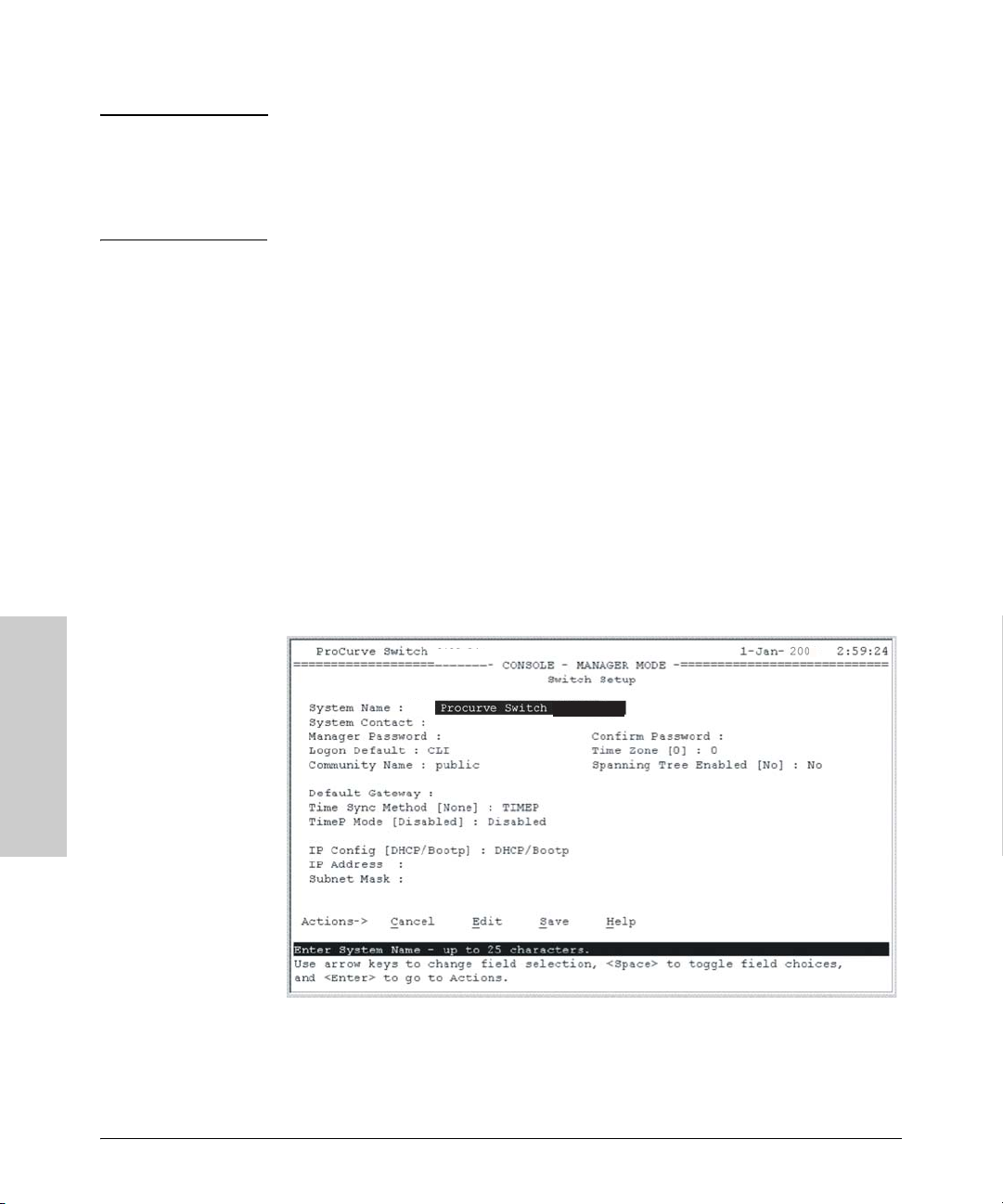
Getting Started With Switch Configuration
Using the Console Setup Screen
Note By default, the switch is configured to acquire an IP address configuration
from a DHCP or Bootp server. To use DHCP/Bootp instead of the manual
method described in this chapter, see “DHCP/Bootp Operation” in the
Management and Configuration Guide, which is on the ProCurve Web site,
www.procurve.com. (See page 5-1 for details.)
Using the Console Setup Screen
The quickest and easiest way to minimally configure the switch for management and password protection in your network is to use a direct console
connection to the switch, start a console session, and access the Switch Setup
screen.
1. Using the method described in the preceding section, connect a terminal
device to the switch and display the switch console command (CLI)
prompt (the default display).
The CLI prompt appears displaying the switch model number:
ProCurve Switch 3500yl-48G#
2. At the prompt, enter the setup command to display the Switch Setup
screen. The following illustration shows the Setup screen with the default
settings.
Getting Started With Switch
3500yl-48G
3500yl-48G
5
Configuration
Figure 3-1. CLI switch setup screen.
3. Use the
[Tab] key to select the Manager Password field and enter a manager
password of up to 16 characters.
3-2
Page 57

Getting Started With Switch Configuration
Using the Console Setup Screen
4. [Tab] to the IP Config (DHCP/Bootp) field and use the Space bar to select the
Manual option.
5.
[Tab] to the IP Address field and enter the IP address that is compatible with
your network.
6.
[Tab] to the Subnet Mask field and enter the subnet mask used for your
network.
7. Press [
Enter], then [S] (for Save).
Here is some information on the fields in the Setup screen. For more information on these fields, see the Management and Configuration Guide, which is
on the ProCurve Web site, www.procurve.com. (See page 5-1 for details.):
Parameter Default
System Name blank Optional; up to 25 characters, including spaces
System Contact blank Optional; up to 48 characters, including spaces
Manager Password blank Recommended; up to 16 characters (no blank spaces)
Logon Default CLI The default setting selects the command line interface for console access.
The alternative is the menu interface.
Time Zone 0 (none) Optional; 1440 to -1440. The number of minutes your location is to the West (-)
or East (+) of GMT.
Community Name public Default setting recommended.
Spanning Tree Enabled No Default setting recommended unless STP is already running on your network
or the switch will be used in complex network topologies.
Default Gateway blank Optional; Enter the IP address of the next-hop gateway node if network traffic
needs to be able to reach off-subnet destinations.
Time Sync Method None Optional; The protocol the switch uses to acquire a time signal. The options
are SNTP and TimeP.
TimeP Mode Disabled Optional; The method the switch uses to acquire the TimeP server address.
IP Config (DHCP/Bootp) DHCP/Bootp Set to Manual unless a DHCP/Bootp server is used on your network to
configure IP addressing.
IP Address xxx.xxx.xxx.xxx Recommended; If you set IP Config to Manual, then enter an IP address
compatible with your network.
Note: The IP address and subnet mask assigned for the switch must be compatible with the IP addressing used in
your network. For more information on IP addressing, see the Management and Configuration Guide, which is on the
ProCurve Web site at www.procurve.com. See page 5-1 for details.
Subnet Mask xxx.xxx.xxx.xxx Recommended; If you entered an IP address, then enter a subnet mask
compatible with your network.
Getting Started With Switch
Configuration
3-3
Page 58

Getting Started With Switch Configuration
Where to Go From Here
Where to Go From Here
The above procedure configures your switch with a Manager password, IP
address, and subnet mask. As a result, with the proper network connections,
you can now manage the switch from a PC equipped with Telnet, a web
browser interface, or from an SNMP-based network management station
using a tool such as ProCurve Manager.
Some basic information on managing your switch is included in the next
section. For more information on the console, web browser, and SNMP
management interfaces and all the features that can be configured on the yl
switches, see the Management and Configuration Guide, which is on the
ProCurve Web site, www.procurve.com. (See page 5-1 for details.)
To Recover from a Lost Manager Password
If you cannot start a console session at the manager level because of a lost
Manager password, you can clear all passwords and user names by getting
physical access to the switch and pressing and holding the Clear button for a
full second.
Getting Started With Switch
Configuration
3-4
Page 59

Using the IP Address for Remote Switch Management
Getting Started With Switch Configuration
Using the IP Address for Remote Switch
Management
With your yl switch, you can use the switch’s IP address to manage the switch
from any PC that is on the same subnet as the switch. You can use either a
Telnet session or a standard web browser to manage the switch.
Starting a Telnet Session
To access the switch through a Telnet session, follow these steps:
1. Make sure the switch is configured with an IP address and that the switch
is reachable from the PC that is running the Telnet session (for example,
by using a Ping command to the switch’s IP address).
2. Start the Telnet program on a PC that is on the same subnet as the switch
and connect to the switch’s IP address.
3. You will see the copyright page and the message “Press any key to
continue”. Press a key, and you will then see the switch console command
(CLI) prompt, for example:
ProCurve Switch 3500yl-48G#
Getting Started With Switch
Enter help or ? to see a list of commands that can be executed at the
prompt. Entering any command followed by help provides more detailed
context help information about the command. Entering any command
followed by ? displays a list of options that are available at that point in
the command entry.
Starting a Web Browser Session
Your yl Switch can be managed through a graphical interface that you can
access from any PC or workstation on the network by running your web
browser and typing in the switch’s IP address as the URL. No additional
software installation is required to make this interface available; it is included
in the switch’s onboard software.
3-5
Configuration
Page 60

Getting Started With Switch Configuration
Using the IP Address for Remote Switch Management
The operating systems, web browsers, and Java support required to manage
the switch through the browser interface are listed in the following table:
Operating System Internet Explorer Java Version
Windows 2000 SP4 5.5 SP2, 6.0 SP1 1.3.1_12 and 1.4.2_05
Windows XP SP1a 6.0 SP1 1.3.1_12 and 1.4.2_05
Windows Server 2003 6.0 SP1 1.3.1_12 and 1.4.2_05
The following illustration shows a typical web browser interface screen.
Getting Started With Switch
ProCurve Switch 3500yl-48G - Status: Information
J8693A ProCurve Switch 3500yl-48G
xl
xl
PoE Status
Configuration
Figure 3-2. Web browser interface screen.
For more information on using the web browser interface, see the Management and Configuration Guide, which is on the ProCurve Web site,
www.procurve.com. (See page 5-1 for details.)
3-6
An extensive help system is also available for the web browser interface. To
access the help system though, the subnet on which the switch is installed
must have access to the internet, or ProCurve Manager needs to be installed
on a network management station that is on the subnet.
Page 61

4
Replacing Components
This chapter shows you how to remove and install the following components:
■ Fan tray (see page 4-1)
■ Battery (see page 4-3)
Hot Swapping These components can not be hot swapped. The switch must be powered off
to replace both of these components.
Caution The ProCurve 3500yl and 6200yl Switches and its components are sensitive to
static discharge. Use an antistatic wrist strap and observe all static
precautions when replacing components.
Replacing the fan tray
The fan tray is not hot swappable. Replacing the fan try must be done during
scheduled downtime. When a fan fails the Fan Status LED on the switch will
blink simultaneously with the switch Fault LED. In this case, the entire fan
tray needs to be replaced. Individual fans cannot be replaced.
WARNING To avoid the possibility of electric shock, all power cords must be
disconnected from the switch before starting this procedure.
To replace a fan tray:
1. Disconnect the power cables from the switch.
2. Using a Torx T-10 screwdriver remove all the screws securing the top of
the switch and remove the top.
Replacing Components
4-1
Page 62

Replacing Components
Replacing the fan tray
3. Remove the retaining screw securing the fan tray, disconnect the fan tray
cable connector, and lift the fan tray assembly out.
Retaining
Screw
Cable
Connector
Figure 4-1. Fan tray retaining screw and cable.
4. Install the new fan tray assembly, reconnect the fan tray cable connector,
reinstall and tighten the retaining screw.
5. Reinstall the top of the switch. Align the top cover pin with the hole.
Replacing Components
Top Cover Pin
Alignment
Hole
Figure 4-2. Alignment of the top cover pin with the alignment hole.
6. Reinstall and tighten all the screws securing the top.
7. Reconnect the power cable to the switch.
4-2
Page 63

Replacing Components
Replacing the Battery
Replacing the Battery
The battery is used to keep time for the internal switch clock. There is not
LED indicator for when the battery no longer has sufficient power. The only
indication will be the internal clock will not keep the correct time. The battery
is not hot swappable. Replacing the battery must be done during scheduled
downtime.
WARNING ■ The battery requires special handling at end-of-life. The battery
can explode or cause burns if disassembled, charged, or exposed
to water, fire or high temperature. After replacing the battery,
properly dispose of used battery according to instructions.
■ There is a risk of explosion if the battery is replaced by an
incorrect type. Ensure to replace the battery with the same type.
Installing a New Battery
WARNING To avoid the possibility of electric shock, all power cords must be
disconnected from the switch before starting this procedure.
To install (or replace) a Battery:
1. Disconnect the power cable from the switch.
2. Using a Torx T-10 screwdriver remove all the screws securing the top of
the switch and remove the top.
3. Remove the used battery and dispose of properly.
Battery
Figure 4-3. Battery location.
Replacing Components
4-3
Page 64

Replacing Components
Replacing the Battery
4. Insert a new battery with the lettering and the plus “+” sign facing up.
Be sure to replace with the same type of battery.
5. Reinstall the top of the switch. Ensure you correctly align the top cover
pin.
Top Cover Pin
Alignment
Hole
Figure 4-4. Alignment of the top cover pin with the alignment hole.
6. Reinstall and tighten all the screws securing the top.
Replacing Components
7. Reconnect the power cable to the switch.
ATTENTION ll y a danger d'explosion s'il y a remplacement incorrect de la batterie.
Remplacer uniquement avec une batterie du même type ou d'un type
équivalent recommandé par le constructeur.
Mettre au rebut les batteries usagées conformément aux instructions du
fabricant.
4-4
Page 65

Troubleshooting
This chapter describes how to troubleshoot your switch. This document
describes troubleshooting mostly from a hardware perspective. You can
perform more in-depth troubleshooting on the switch using the software tools
available with the switch, including the full-featured console interface, the
built-in web browser interface, and ProCurve Manager, the SNMP-based
network management tool. For more information, see the chapter “Troubleshooting” in the Management and Configuration Guide, which is on the
ProCurve Web site at www.procurve.com. To display the list of downloadable
manuals, click on the following links:
Technical support
Product manuals (all)
(You may want to bookmark this Web page for easy access in the future.)
5
Troubleshooting
ProCurve Switch 3500yl or 6200yl Series.
This chapter describes the following:
■ Basic Troubleshooting Tips (page 5-2)
■ Diagnosing with the LEDs (page 5-4)
■ Proactive Networking Tools (page 5-8)
■ Hardware Diagnostic Tests (page 5-9)
■ Restoring the Factory Default Configuration (page 5-11)
■ Downloading New Switch Software (page 5-12)
■ HP Customer Support Services (page 5-12)
5-1
Page 66

Troubleshooting
Basic Troubleshooting Tips
Basic Troubleshooting Tips
Most problems are caused by the following situations. Check for these items
first when starting your troubleshooting:
Troubleshooting
■ Connecting to devices that have a fixed full-duplex configuration.
The RJ-45 ports are configured as “Auto”. That is, when connecting to
attached devices, the switch will operate in one of two ways to determine
the link speed and the communication mode (half duplex or full duplex):
• If the connected device is also configured to Auto, the switch will
automatically negotiate both link speed and communication mode.
• If the connected device has a fixed configuration, for example
100 Mbps,
at half or full duplex, the switch will automatically sense
the link speed, but will default to a communication mode of half
duplex.
Because the switch behaves in this way (in compliance with the IEEE
802.3 standard), if a device connected to the switch has a fixed configuration at full duplex, the device will not connect correctly to the switch.
The result will be high error rates and very inefficient communications
between the switch and the device.
5-2
Make sure that all devices connected to the switch are configured to auto
negotiate, or are configured to connect at half duplex (all hubs are
configured this way, for example).
■ Faulty or loose cables. Look for loose or obviously faulty connections.
If they appear to be OK, make sure the connections are snug. If that does
not correct the problem, try a different cable.
■ Non-standard cables. Non-standard and miswired cables may cause
network collisions and other network problems, and can seriously impair
network performance. Use a new correctly-wired cable or compare your
cable to the cable in appendix B, “Cables and Connectors” for pinouts and
correct cable wiring. A category 5 cable tester is a recommended tool for
every 100Base-TX and 1000Base-T network installation.
■ Improper Network Topologies. It is important to make sure you have
a valid network topology. Common topology faults include excessive
cable length and excessive repeater delays between end nodes. If you have
network problems after recent changes to the network, change back to
the previous topology. If you no longer experience the problems, the new
topology is probably at fault. Sample topologies are shown at the end of
chapter 2 in this book, and some topology configuration guidelines can
be found online at the ProCurve web site, www.procurve.com.
Page 67

Basic Troubleshooting Tips
Troubleshooting
In addition, you should make sure that your network topology contains
no data path loops. Between any two end nodes, there should be only
one active cabling path at any time. Data path loops will cause broadcast
storms that will severely impact your network performance.
For your switch, if you wish to build redundant paths between important
nodes in your network to provide some fault tolerance, you should enable
Spanning Tree Protocol support on the switch. This ensures only one
of the redundant paths is active at any time, thus avoiding data path loops.
Spanning Tree can be enabled through the switch console, the web
browser interface, or ProCurve Manager.
The Series 3500yl Switch devices also support Trunking, which allows
multiple network cables to be used for a single network connection
without causing a data path loop. For more information on Spanning Tree
and Trunking, see the Management and Configuration Guide, which is
on the ProCurve Web site at www.procurve.com. See page 5-1 for details.
■ Check the port configuration. A port on your switch may not be
operating as you expect because it has been put into a “blocking” state by
Spanning Tree, GVRP (automatic VLANs), or LACP (automatic trunking).
(Note that the normal operation of the Spanning Tree, GVRP, and LACP
features may put the port in a blocking state.) Or, the port just may have
been configured as disabled through software.
Troubleshooting
Use the switch console to determine the port’s configuration and verify
that there is not an improper or undesired configuration of any of the
switch features that may be affecting the port. For more information, see
the Management and Configuration Guide, which is on the ProCurve
Web site at www.procurve.com. See page 5-1 for details.
5-3
Page 68

Troubleshooting
Diagnosing with the LEDs
Diagnosing with the LEDs
Table 4-1 shows LED patterns on the switch and the switch modules that
indicate problem conditions.
1. Check in the table for the LED pattern you see on your switch.
2. Refer to the corresponding diagnostic tip on the next few pages.
Troubleshooting
Table 5-1. LED Error Indicators
LED Pattern Indicating Problems
Module (Mdl)
Power Fault
off with
power cord
plugged in
on prolonged on * * prolonged
on blink orange
on blink orange
on blink orange
on off * * off * off with cable
on off * * off * on, but the port is
on blink orange
on blink orange
on blink orange
*** ***
Status**
†
†
†
†
†
†
* * blink
* * off blink
see tip 5 * blink
* blink
* * blink
F
blink orange
B
blink orange
RPS
Status
orange
†
* blink
†
EPS
Status
*** *
†
orange
Fan
Tes t
on
orange
orange
** *
†
orange
Status
†
orange
†
†
(in Link view mode)
**
**
†
* blink orange
communicating
**
Port LED
connected
*
not
Diag
Tip s
➊
➋
➌
➍
†
➎
➏
➐
➑
➒
➓
* This LED is not important for the diagnosis.
†
The blinking behavior is an on/off cycle once every 1.6 seconds, approximately.
** The Module Status LED is located on the module in the rear of the switch.
F - Front
B - Back
5-4
Page 69

Diagnostic Tips:
Diagnosing with the LEDs
Troubleshooting
Tip Problem Solution
➊
➋
➌
➍
The switch is not
plugged into an
active AC power
source, or the
switch’s power
supply may have
failed. The
switch will not
power up if the
top is off.
A switch
hardware failure
has occurred. All
the LEDs will stay
on indefinitely.
The switch has
experienced a
software failure
during self test.
One or both of the
switch cooling
fans may have
failed.
1. Verify the power cord is plugged into an active power source and to the switch. Make
sure these connections are snug.
2. Try power cycling the switch by unplugging and plugging the power cord back in.
3. If the Power LED is still not on, verify that the AC power source works by plugging
another device into the outlet. Or try plugging the switch into a different outlet or try a
different power cord.
If the power source and power cord are OK and this condition persists, the switch power
supply may have failed. Call your ProCurve authorized LAN dealer, or use the electronic
support services from ProCurve to get assistance. See the Customer Support/Warranty
booklet for more information.
Try power cycling the switch. If the fault indication reoccurs, the switch may have failed.
Call your ProCurve authorized LAN dealer, or use the electronic support services from HP
to get assistance. See the Customer Support/Warranty booklet for more information.
1. Try resetting the switch by pressing the Reset button on the front of the switch, or by
power cycling the switch.
2. If the fault indication reoccurs, attach a console to the switch (as indicated in chapter
2) and configure it to operate at 9600 baud. Then, reset the switch. Messages should
appear on the console screen and in the console log identifying the error condition.
You can view the console log at that point by selecting it from the console Main Menu.
If necessary to resolve the problem, contact your ProCurve authorized LAN dealer, or use
the electronic support services from ProCurve to get assistance. See the Customer
Support/Warranty booklet for more information.
Try disconnecting power from the switch and wait a few moments. Then reconnect the
power to the switch and check the LEDs again. If the error indication reoccurs, one or
both of the fans has failed. The switch has two fans and may continue to operate under
this condition if the ambient temperature does not exceed normal room temperature, but
for best operation, the switch should be replaced. Contact your ProCurve authorized LAN
dealer, or use the electronic support services from ProCurve to get assistance. See the
Customer Support/Warranty booklet for more information.
Troubleshooting
➎
The network port
for which the LED
is blinking has
experienced a
self test or
initialization
failure.
If the Mdl Status
LED is blinking,
the affected port
is on the yl
Module.
Try power cycling the switch. If the fault indication reoccurs, the switch port may have
failed. Call your ProCurve authorized LAN dealer, or use the electronic support services
from ProCurve to get assistance. See the Customer Support/Warranty booklet for more
information.
If the port is a pluggable, verify it is one of the pluggables supported by the switch.
Unsupported pluggables will be identified with this fault condition. The supported miniGBICs are listed in Chapter 2, “Installing the Switch” on page 2-1, supported transceivers
are listed in the ProCurve Switch yl Module Installation Guide. The mini-GBICs are also
tested when they are “hot-swapped”—installed or changed while the switch is powered
on.
To verify the port has failed, try removing and reinstalling the mini-GBIC without having
to power off the switch. If the port fault indication reoccurs, you will have to replace the
mini-GBIC.
continued on the next page
5-5
Page 70

Troubleshooting
Diagnosing with the LEDs
Tip Problem Solution
The network
➏
connection is not
working
properly.
Troubleshooting
Try the following procedures:
• For the indicated port, verify both ends of the cabling, at the switch and the connected
device, are connected properly.
• Verify the connected device and switch are both powered on and operating correctly.
• Verify you have used the correct cable type for the connection:
– For twisted-pair connections to the fixed 10/100 or 10/100/1000 ports, if the port is
configured to “Auto” (auto negotiate), either straight-through or crossover cables
can be used because of the switch’s “HP Auto-MDIX” feature and the Auto MDI/
MDI-X feature of the 10/100/1000-T port.
Note: If the switch port configuration is changed to one of the fixed configuration
options (for example, 100 Mbps/Full Duplex), then the port operates as MDI-X only
and you must use the correct type of cable for the connection. In general, for
connecting an end node (MDI port) to the switch, use straight-through cable; for
connecting to MDI-X ports on hubs, other switches, and routers, use crossover
cable.
– For fiber-optic connections, verify the transmit port on the switch is connected to
the receive port on the connected device, and the switch receive port is connected
to the transmit port on the connected device.
• For the dual-personality 10/100/1000-T ports, be sure a mini-GBIC is not installed in the
associated slot.
• For 1000Base-T connections, verify that the network cabling complies with the IEEE
802.3ab standard. the cable should be installed according to the ANSI/TIA/EIA-568A-5 specifications. Cable testing should comply with the stated limitations for Attenuation, Near-End Crosstalk, Far-End Crosstalk, Equal-Level Far-End Crosstalk (ELFEXT),
Multiple Disturber ELFEXT, and Return Loss.
The cable verification process must include all patch cables from any end devices,
including the switch, to any patch panels in the cabling path.
• Verify the port has not been disabled through a switch configuration change.
You can use the console interface, or, if you have configured an IP address on the
switch, use the web browser interface, or ProCurve Manager network management
software to determine the state of the port and re-enable the port if necessary.
• Verify the switch port configuration matches the configuration of the attached device.
For example, if the switch port is configured as “Auto”, the port on the attached device
also MUST be configured as “Auto”. Depending on the port type, twisted-pair or fiberoptic, if the configurations don’t match, the results could be a very unreliable connection, or no link at all.
• If the other procedures don’t resolve the problem, try using a different port or a different
cable.
5-6
Page 71

Tip Problem Solution
Diagnosing with the LEDs
Troubleshooting
➐
➑
➒
The port may be
improperly
configured, or
the port may be in
a “blocking”
state by the
normal operation
of the Spanning
Tree, LACP, or
IGMP features.
An RPS is
connected but
may have
experienced a
fault.
An EPS is
connected but
the switch has
experienced a
fault.
Use the switch console to see if the port is part of a dynamic trunk (through the LACP
feature) or to see if Spanning Tree is enabled on the switch, and to see if the port may
have been put into a “blocking” state by those features. The show lacp command displays
the port status for the LACP feature; the show spanning-tree command displays the port
status for Spanning Tree.
Also check the Port Status screen using the show interfaces command to see if the port
has been configured as “disabled”.
Other switch features that may affect the port operation include VLANs and IGMP. Use
the switch console to see how the port is configured for these features.
For software troubleshooting tips, see the chapter “Troubleshooting” in the Management
and Configuration Guide, which is on the ProCurve Web site at www.procurve.com. See
page 5-1 for details.
Make sure also, the device at the other end of the connection is indicating a good link to
the switch. If it is not, the problem may be with the cabling between the devices or the
connectors on the cable.
Check the RPS unit to make sure it is plugged in to an active power source. If this is ok
but the LEDs are still blinking, the power supply in the RPS unit may have failed. Try
reversing R1 and R2 power cords. Also check the log files of the connected switch for
more information. This condition can also be caused by an RPS unit fan failure or and
over temperature condition. If necessary to resolve the problem, contact your ProCurve
authorized LAN dealer, or use the electronic support services from ProCurve to get
assistance. See the Customer Support/Warranty booklet for more information.
Check the EPS unit to make sure it is plugged in to an active power source. If this is ok
but the LEDs are still blinking, the power supply in the EPS unit may have failed. Try
reversing EPS1 and EPS2 power cords. Also check the log files of the connected switch
for more information. This condition can also be caused by an RPS unit fan failure or and
over temperature condition. If necessary to resolve the problem, contact your ProCurve
authorized LAN dealer, or use the electronic support services from ProCurve to get
assistance. See the Customer Support/Warranty booklet for more information.
Troubleshooting
➓
Expansion yl
module is
plugged in but
has experienced
a fault.
Check the rear of the switch. Check the module LEDs for indications. This will only occur
during an initialization self test.
5-7
Page 72

Troubleshooting
Proactive Networking
Proactive Networking
The ProCurve Series 3500yl and 6200yl Switches have built-in management
capabilities that proactively help you manage your network including:
Troubleshooting
■ finding and helping you fix the most common network error conditions
(for example, faulty network cabling, and non-standard network topologies)
■ informing you of the problem with clear, easy-to-understand messages
■ recommending network configuration changes to enhance the perfor-
mance of your network
The following interfaces provide tests, indicators, and an event log that can
be used to monitor the switch and its network connections and to help you
take advantage of these proactive networking features:
■ ProCurve Manager - an SNMP-based network management tool that is
included with your switch.
■ A graphical web browser interface that you can use to manage your switch
from a PC running a supported web browser, for example Microsoft
Internet Explorer, and Netscape Communicator.
■ A full-featured easy-to-use console interface that you can access by
connecting a standard terminal or PC running a terminal emulator to the
switch’s console port. The cable to make that connection is provided with
your switch. The console interface is also accessible through a Telnet
connection.
5-8
For more information on using these software tools to diagnose and manage
your switch, see the “Troubleshooting” chapter in the Management and
Configuration Guide, which is on the ProCurve Web site at
www.procurve.com. See page 5-1 for details.
Page 73

Hardware Diagnostic Tests
Troubleshooting
Hardware Diagnostic Tests
Testing the Switch by Resetting It
If you believe the switch is not operating correctly, you can reset the switch
to test its circuitry and operating code. To reset a switch, either:
■ unplug and plug in the power cord (power cycling)
■ press the Reset button on the front of the switch
Power cycling the switch and pressing the Reset button both cause the switch
to perform its power-on self test, which almost always will resolve any
temporary operational problems. These reset processes also cause any
network traffic counters to be reset to zero, and cause the System Up Time
timer to reset to zero.
Checking the Switch LEDs
The self test passes if the Fault and Self Test LEDs on the front of the switch
go off after approximately 50 seconds. If these LEDs stay on longer than 60
seconds or begin blinking, there may be a problem with the switch.
See “Diagnosing With the LEDs” on page 5-4 for information on interpreting
the LED patterns and LED behaviors in chapter one.
Troubleshooting
Checking Console Messages
Useful diagnostic messages may be displayed on the console screen when the
switch is reset. As described in chapter 2 under step 7, “Connect a Console to
the Switch”, connect a PC running a VT-100 terminal emulator program or a
standard VT-100 terminal to the switch’s Console Port and configure it to run
at 9600 baud, and with the other terminal communication settings shown on
page 2-22. Then, when you reset the switch, note the messages that are
displayed. Additionally, you can check the switch event log, which can be
accessed from the console using the show log command, or from the console
Main Menu.
5-9
Page 74

Troubleshooting
Hardware Diagnostic Tests
Testing Twisted-Pair Cabling
Network cables that fail to provide a link or provide an unreliable link between
the switch and the connected network device may not be compatible with the
IEEE 802.3 Type 10Base-T, 100Base-TX, or 1000Base-T standards. The twistedpair cables attached to the Switch must be compatible with the appropriate
standards. To verify your cable is compatible with these standards, use a
Troubleshooting
qualified cable test device.
Testing Switch-to-Device Network Communications
You can perform the following communication tests to verify the network is
operating correctly between the switch and any connected device that can
respond correctly to the communication test.
■ Link Test -- a physical layer test that sends IEEE 802.2 test packets to any
device identified by its MAC address.
■ Ping Test -- a network layer test used on IP networks that sends test
packets to any device identified by its IP address.
These tests can be performed through the switch console interface from a
terminal connected to the switch or through a Telnet connection, or from the
switch’s web browser interface. For more information, see the Management
and Configuration Guide, which is on the ProCurve Web site at
www.procurve.com. See page 5-1 for details.
5-10
These tests can also be performed from an SNMP network management
station running a program that can manage the switch, for example, ProCurve
Manager.
Testing End-to-End Network Communications
Both the switch and the cabling can be tested by running an end-to-end
communications test -- a test that sends known data from one network device
to another through the switch. For example, if you have two PCs on the
network that have LAN adapters between which you can run a link-level test
or Ping test through the switch, you can use this test to verify that the entire
communication path between the two PCs is functioning correctly. See your
LAN adapter documentation for more information on running a link test or
Ping test.
Page 75

Restoring the Factory Default Configuration
Troubleshooting
Restoring the Factory Default
Configuration
As part of your troubleshooting process on the switch, it may become necessary to return the switch configuration to the factory default settings. This
process momentarily interrupts the switch operation, clears any passwords,
clears the console event log, resets the network counters to zero, performs a
complete self test, and reboots the switch into its factory default configuration
including deleting the IP address, if one is configured.
Note This process removes all switch configuration changes you have made from
the factory default settings. This includes, for example, configuration of
VLANs, Spanning Tree, trunks, and stacking. Returning the configuration of
these features to their factory default settings (usually disabling them) may
result in network connectivity issues.
If the switch has a valid configuration, and you are restoring the factory default
settings for a reason other than configuration problems, you should save the
switch configuration prior to performing the factory default reset. Then, after
the reset and resolution of the original problem, you can restore the saved
configuration to the switch. For both the save and restore processes, you can
use the console copy command. For more information on this command, see
the Management and Configuration Guide, which is on the ProCurve Web
site at www.procurve.com. See page 5-1 for details.
Troubleshooting
You can restore the factory default configuration either on the switch itself,
or through the switch console.
To execute the factory default reset on the switch, perform these steps:
1. Using pointed objects, simultaneously press both the Reset and Clear
buttons on the front of the switch.
2. Continue to press the Clear button while releasing the Reset button.
3. When the Self Test LED begins to blink, release the Clear button. It takes
approximately 25 seconds before the Self Test LED will begin to blink.
The switch will then complete its self test and begin operating with its
configuration restored to the factory default settings.
To restore the factory default configuration using the console, execute the
erase startup-config command from the console command prompt.
5-11
Page 76

Troubleshooting
Downloading New Switch Software
Downloading New Switch Software
When product enhancements occur for the switch, new software can be
downloaded to the switch through several methods, for product enhancements and new features. For more information, see the Management and
Configuration Guide, which is on the ProCurve Web site at
Troubleshooting
www.procurve.com. See page 5-1 for details.
The new switch software would be available on the ProCurve Web site,
www.procurve.com.
HP Customer Support Services
If you are still having trouble with your switch, Hewlett-Packard offers support
24 hours a day, seven days a week through the use of a number of automated
electronic services. See the Customer Support/Warranty booklet that came
with your switch for information on how to use these services to get technical
support. The ProCurve Web site, www.procurve.com also provides up-to-date
support information.
5-12
Additionally, your ProCurve authorized network reseller can provide you with
assistance, both with services that they offer and with services offered by
ProCurve.
Before Calling Support
Before calling your networking dealer or ProCurve Support, to make the
support process most efficient, you first should have retrieved the following
information:
Information Item Information Location
• product identification, including miniGBICs
• details about the switch’s status including the software (OS) version, a copy of
the switch configuration, a copy of the
switch Event Log, and a copy of the
switch status and counters information
• copy of your network topology map, including network addresses assigned to
the relevant devices
the front of the switch and on labels on the
mini-GBICs
switch console: show tech command
your network records
Page 77

Specifications
Physical
A
3500yl-24G (J8692A) and
6200yl-24G(J8992A)
Width: 44.3 cm (17.42 in) 44.3 cm (17.42 in)
Depth: 39.2 cm (15.43 in) 43.0 cm (16.9 in)
Height: 4.4 cm (1.7 in) 4.4 cm (1.7 in)
Weight: 6.4 kg (14.10 lbs) 7.3 kg (16.1 lbs)
3500yl-48G (J8693A)
Electrical
The switch automatically adjusts to any voltage between 100-127 and 200-240
volts and either 50 or 60 Hz.
3500yl-24G-PWR
(J8692A)
AC voltage: 100-127/200-240 volts 100-127/200-240 volts 100-127/200-240 volts
Maximum current: 10.0A/5.0A 4.0A/2.0A 10.0A/5.0A
Frequency range: 50/60 Hz 50/60 Hz 50/60 Hz
6200yl-24G
(J8992A)
3500yl-48G-PWR
(J8693A)
Environmental
Specifications
Operating Non-Operating
1
Temperature: 0°C to 55°C (32°F to 131°F)
Relative humidity:
(non-condensing)
Maximum altitude: 4.6 km (15,000 ft) 4.6 km (15,000 ft)
1
If you are installing either the Series 3500yl or 6200yl Switches using any of the X2
transceivers, the operating ambient temperature should not exceed 40°C (104°F).
See transceiver specifications.
15% to 95% at 40°C (104°F) 15% to 90% at 65°C (149°F)
-40°C to 70°C (-40°F to 158°F)
A-1
Page 78

Specifications
Acoustic
ProCurve Switch 3500yl-24G-PWR (J8692A) and ProCurve Switch 6200yl-24G-mGBIC
(J8992A)
Geraeuschemission LpA=49.3 dB am fiktiven Arbeitsplatz nach
DIN 45635 T.19
Noise Emission LpA=49.3 dB at virtual workspace according to
DIN 45635 T.19
ProCurve Switch 3500yl-48G-PWR (J8692A)
Geraeuschemission LpA=52 dB am fiktiven Arbeitsplatz nach
DIN 45635 T.19
Noise Emission LpA=52 dB at virtual workspace according to
DIN 45635 T.19
Specifications
Connectors
■ The 10/100/1000 Mbps RJ-45 twisted-pair ports are compatible with the
following standards:
• IEEE 802.3ab 1000Base-T
• IEEE 802.3u 100Base-TX
• IEEE 802.3 10Base-T
■ The 1000 Mbps LC fiber-optic ports on the Gigabit-SX and Gigabit-LX mini-
GBIC transceivers are compatible with the IEEE 802.3z Gigabit-SX and
Gigabit-LX standards.
Safety
Complies with:
■ EN60950
■ CSA 22.2 No. 60950
■ UL 60950
■ IEC 60950
A-2
Page 79

Lasers
The following products are Class 1 Laser Products.
Laser Klasse 1:
■ The 10-GbE X2-SC SR transceiver
■ The 10-GbE X2-SC LR transceiver
■ The 10-GbE X2-SC ER transceiver
The following products are Class 1m Laser Products.
Laser Klasse 1m:
■ The 10-GbE X2 SR-SC transceiver
Running H/F 1
The transceivers comply with IEC 60825.
Specifications
A-3
Page 80

Page 81

Switch Ports and Network Cables
This appendix includes switch connector information and network cable
information for cables that should be used with the Switch 3500, including
minimum pin-out information and specifications for twisted-pair cables.
Note Incorrectly wired cabling is the most common cause of problems for LAN
communications. ProCurve recommends that you work with a qualified LAN
cable installer for assistance with your cabling requirements.
Switch Ports
The fixed RJ-45 10/100Base-TX and 10/100/1000Base-T ports on the switch
accept 100-ohm unshielded and shielded twisted-pair cable with RJ-45
connectors as described on the next page.
Twi sted- Pair C ables
B
10 Mbps Operation Category 3, 4, or 5 100-ohm unshielded twisted-pair (UTP)
or shielded twisted-pair (STP) cable, complying with IEEE
802.3 Type 10Base-T specifications, fitted with RJ-45
connectors
100 Mbps Operation Category 5 100-ohm UTP or STP cable, complying with
IEEE 802.3u 100Base-TX specifications, fitted with RJ-45
connectors
1000 Mbps Operation Category 5 100-ohm 4-pair UTP or STP cable, complying
with IEEE 802.3ab 1000Base-T specifications, fitted with
RJ-45 connectors—Category 5e or better is recommended
(please see “Note on 1000Base-T Cable Requirements”,
below)
Note on 1000Base-T Cable Requirements. The Category 5 networking
cables that work for 100Base-TX connections should also work for
1000Base-T, as long as all four-pairs are connected. But, for the most robust
connections you should use cabling that complies with the Category 5e
specifications, as described in Addendum 5 to the TIA-568-A standard (ANSI/
TIA/EIA-568-A-5).
B-1
Switch Ports and Network
Cables
Page 82

Switch Ports and Network Cables
Because of the increased speed provided by 1000Base-T (Gigabit-T), network
cable quality is more important than for either 10Base-T or 100Base-TX.
Cabling plants being used to carry 1000Base-T networking must comply with
the IEEE 802.3ab standards. In particular, the cabling must pass tests for
Attenuation, Near-End Crosstalk (NEXT), and Far-End Crosstalk (FEXT).
Additionally, unlike the cables for 100Base-TX, the 1000Base-T cables must
pass tests for Equal-Level Far-End Crosstalk (ELFEXT) and Return Loss.
When testing your cabling, be sure to include the patch cables that connect
the switch and other end devices to the patch panels on your site. The patch
cables are frequently overlooked when testing cable and they must also
comply with the cabling standards.
Fiber-Optic
1000Base-SX 62.5/125 μm or 50/125 μm (core/cladding) diameter, graded-
1000Base-LX single mode fiber-optic cables, complying with the ITU-T
Cables
1000Base-LH single mode fiber-optic cables, complying with the ITU-T
index, multimode fiber-optic cables, complying with the
ITU-T G.651 and ISO/IEC 793-2 Type A1b or A1a respectively, fitted with LC connectors.
G.652 and ISO/IEC 793-2 Type B1 standards, fitted with LC
connectors
OR
62.5/125 μm or 50/125 μm (core/cladding) diameter, graded-
index, multimode fiber-optic cables, complying with the
ITU-T G.651 and ISO/IEC 793-2 Type A1b or A1a respectively, fitted with LC connectors
Note: Multimode fiber-optic cabling may be used for a
1000Base-LX application, but a mode conditioning patch
cord may be needed. See “Mode Conditioning Patch Cord
for Gigabit-LX” on page B-3 for more information.
G.652 and ISO/IEC 793-2 Type B1 standards, fitted with LC
connectors
Switch Ports and Network
10-GbE SR Multimode fiber-optic cable designed for Gigabit Ethernet: 62.5/
125 μm (core/cladding) diameter or 50/125 μm, 850 nm, low metal
content, complying with the ITU-T G.652 and ISO/IEC 793-2 Type
B1 standards.
10-GbE LR 9/125 μm (core/cladding) diameter, 1310 nm, low metal content,
single mode fiber-optic cables, complying with the ITU-T G.652
and ISO/IEC 793-2 Type B1 standards.
B-2
10-GbE ER 9/125 μm (core/cladding) diameter, 1550 nm, low metal content,
single mode fiber-optic cables, complying with the ITU-T G.652
and ISO/IEC 793-2 Type B1 standards.
Note: Conditioning patch cord cables are not supported on 10-GbE speeds.
Page 83

Mode Conditioning Patch Cord for Gigabit-LX
Switch Ports and Network Cables
Mode Conditioning Patch Cord for
Gigabit-LX
The following information applies to installations in which multimode fiberoptic cables are connected to a Gigabit-LX port.
Note Mode Conditioning Patch Cord cables only apply to one Gigabit operation.
Mode Conditioning Patch Cord cables are not supported for 10 Gigabit
operation.
Unlike Gigabit-SX, which connects to only multimode fiber-optic cabling,
Gigabit-LX can use either single-mode or multimode cable. Multimode cable
has a design characteristic called “Differential Mode Delay”, which requires
that the transmission signals be “conditioned” to compensate for the cable
design and thus prevent resulting transmission errors. Since Gigabit-SX is
designed to operate only with multimode cable, Gigabit-SX mini-GBICs can
provide that transmission conditioning internally.
Gigabit-LX mini-GBICs, since they are designed to operate with both singlemode and multimode cable, do not provide the transmission conditioning
internally. Thus, under certain circumstances, depending on the cable used
and the lengths of the cable runs, an external Mode Conditioning Patch
Cord may need to be installed between the Gigabit-LX transmitting device
and the multimode network cable to provide the transmission conditioning.
Switch Ports and Network
If you experience a high number of transmission errors on the Gigabit-LX
ports, usually CRC or FCS errors, you may need to install one of these patch
cords between the Gigabit-LX port in your switch and your multimode fiberoptic network cabling, and between the Gigabit-LX transmission device and
the network cabling at the other end of the multimode fiber-optic cable run.
A patch cord must be installed at both ends.
The patch cord consists of a short length of single-mode fiber cable coupled
to graded-index multimode fiber cable on the transmit side, and only
multimode cable on the receive side. The section of single-mode fiber is
connected in such a way that it minimizes the effects of the differential mode
delay in the multimode cable.
Note If you are using good quality graded-index multimode fiber cable that adheres
to the standards listed on page 2-5, there should not be a need to use mode
conditioning patch cords. This is especially true if the fiber runs in your
network are relatively short. If you are using single-mode fiber-optic cabling,
there is no need to use mode conditioning patch cords. Connect the singlemode network cable directly to the Gigabit-LX mini-GBIC.
B-3
Cables
Page 84
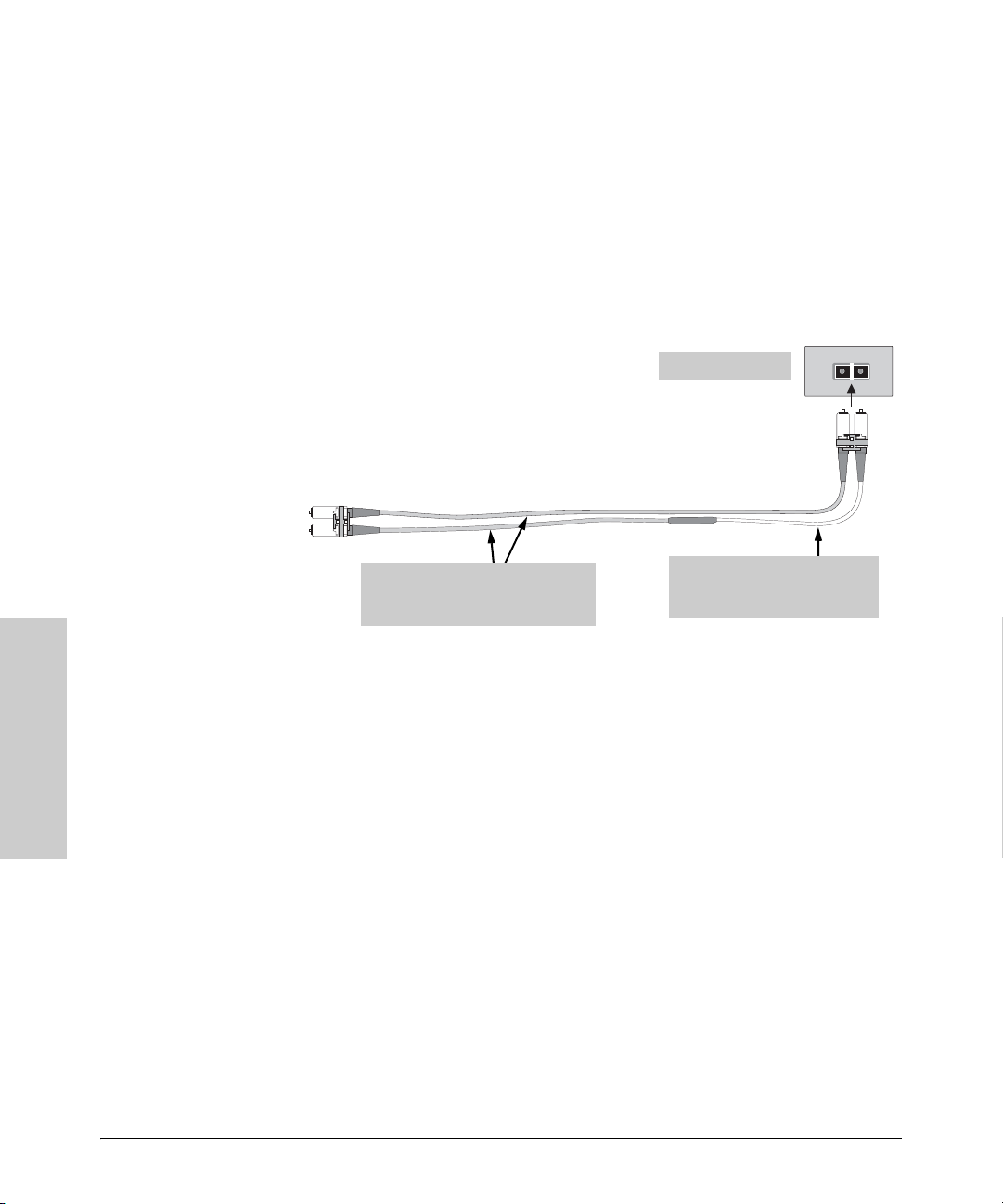
Switch Ports and Network Cables
Mode Conditioning Patch Cord for Gigabit-LX
Installing the Patch Cord
As shown in the illustration below, connect the patch cord to the Gigabit-LX
mini-GBIC with the section of single-mode fiber plugged in to the Tx (transmit)
port. Then, connect the other end of the patch cord to your network cabling
patch panel, or directly to the network multimode fiber.
If you connect the patch cord directly to the network cabling, you may need
to install a female-to-female adapter to allow the cables to be connected
together.
To network
multimode
cabling
Gigabit-LX port
Mode Conditioning
Patch Cord
Tx
Rx
The multimode cable in the patch cord
must match the characteristics of your
network cable
Single-mode section plugs i nto Tx
port on Gigabit-LX Transceiver or
Gigabit-LX mini-GBIC
Make sure you purchase a patch cord that has LC connectors on the end that
connects to the Gigabit-LX mini-GBIC, and has multimode fibers that match
the characteristics of the multimode fiber in your network.
Cables
Recommended Patch Cords
ProCurve maintains a list of recommended Mode Conditioning Patch Cords
Switch Ports and Network
that have been tested and verified to operate correctly with the ProCurve
Gigabit-LX Transceiver and ProCurve Gigabit-LX LC mini-GBIC.
The list is on the ProCurve Web site, www.procurve.com, in the Technical
Support section.
B-4
Page 85

Switch Ports and Network Cables
Twisted-Pair Cable/Connector Pin-Outs
Twisted-Pair Cable/Connector Pin-Outs
Auto-MDIX Feature: The 10/100/1000-T ports support the IEEE 802.3ab
standard, which includes the “Auto MDI/MDI-X” feature. In the default
configuration, “Auto”, the ports on the Switch 3500 all automatically detect
the type of port on the connected device and operate as either an MDI or MDIX port, whichever is appropriate. So for any connection, a straight-through
twisted-pair cable can be used -- you no longer have to use crossover cables,
although crossover cables can also be used for any of the connections.
If you connect a Switch 3500 twisted-pair port to another switch or hub, which
typically have MDI-X ports, the Switch 3500 port automatically operates as an
MDI port. If you connect it to an end node, such as a server or PC, which
typically have MDI ports, the Switch 3500 port operates as an MDI-X port. In
all cases, you can use standard straight-through cables or crossover cables.
If you happen to use a correctly wired crossover cable, though, the switch will
still be able to automatically detect the MDI/MDI-X operation and link
correctly to the connected device.
Other Wiring Rules:
■ All twisted-pair wires used for 10 Mbps, and 100 Mbps operation must be
twisted through the entire length of the cable. The wiring sequence must
conform to EIA/TIA 568-B (not USOC). See “Twisted-Pair Cable Pin
Assignments” later in this appendix for a listing of the signals used on each
pin.
■ For 1000Base-T connections, all four pairs of wires in the cable must be
available for data transmission. See “Note on 1000Base-T Cable Require-
ments” on page B-1 for more information on 1000Base-T cabling.
■ For 10 Mbps connections to the ports, you can use Category 3, 4, or 5
unshielded twisted-pair cable, as supported by the IEEE 802.3 Type
10Base-T standard.
■ For 100 Mbps connections to the ports, use 100-ohm Category 5 UTP or
STP cable only, as supported by the IEEE 802.3u Type 100Base-TX standard.
■ For 1000 Mbps connections, 100-ohm Category 5e or better cabling is
recommended.
Switch Ports and Network
Cables
B-5
Page 86
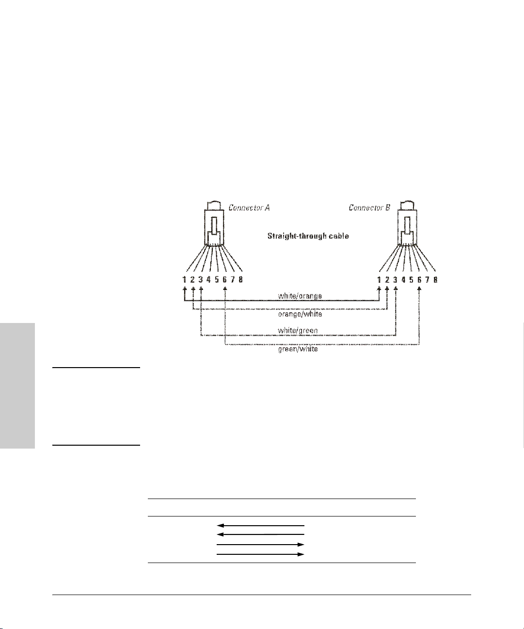
Switch Ports and Network Cables
Twisted-Pair Cable/Connector Pin-Outs
Straight-Through Twisted-Pair Cable for 10 Mbps or 100 Mbps Network Connections
Because of the HP Auto-MDIX operation of the 10/100 ports on the switch, for
all network connections, to PCs, servers or other end nodes, or to hubs or
other switches, you can use straight-through cables.
If any of these ports are given a fixed configuration, for example 100 Mbps/
Full Duplex, the ports operate as MDI-X ports, and straight-through cables
must be then used for connections to PC NICs and other MDI ports.
Cable Diagram
Note Pins 1 and 2 on connector “A” must be wired as a twisted pair to pins 1 and 2
Cables
Switch Ports and Network
.
on connector “B”.
Pins 3 and 6 on connector “A” must be wired as a twisted pair to pins 3 and 6
on connector “B”.
Pins 4, 5, 7, and 8 are not used in this application, although they may be wired
in the cable.
Pin Assignments
Switch End (MDI-X) Computer, Transceiver, or
Other End
Signal Pins Pins Signal
receive +
receive transmit +
transmit -
B-6
1
2
3
6
1
2
3
6
transmit +
transmit receive +
receive -
Page 87
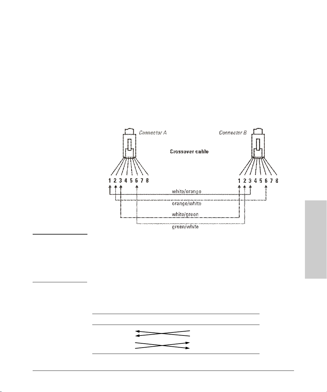
Switch Ports and Network Cables
Twisted-Pair Cable/Connector Pin-Outs
Crossover Twisted-Pair Cable for 10 Mbps or 100 Mbps Network Connection
The HP Auto-MDIX operation of the 10/100 ports on the switch also allows
you to use crossover cables for all network connections, to PCs, servers or
other end nodes, or to hubs or other switches.
If any of these ports are given a fixed configuration, for example 100 Mbps/
Full Duplex, the ports operate as MDI-X ports, and crossover cables must be
then used for connections to hubs or switches or other MDI-X network
devices.
Cable Diagram
Note Pins 1 and 2 on connector “A” must be wired as a twisted pair to pins 3 and 6
on connector “B”.
Pins 3 and 6 on connector “A” must be wired as a twisted pair to pins 1 and 2
on connector “B”.
Pins 4, 5, 7, and 8 are not used in this application, although they may be wired
in the cable.
.
Pin Assignments
Switch End (MDI-X) Hub or Switch Port, or Other
MDI-X Port End
Signal Pins Pins Signal
receive +
receive transmit +
transmit -
1
2
3
6
6
3
2
1
transmit transmit +
receive receive +
B-7
Switch Ports and Network
Cables
Page 88
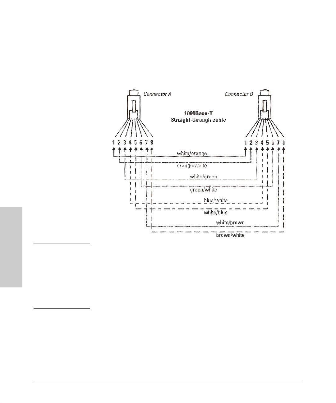
Switch Ports and Network Cables
Twisted-Pair Cable/Connector Pin-Outs
Straight-Through Twisted-Pair Cable for 1000 Mbps Network Connections
1000Base-T connections require that all four pairs or wires be connected.
Cable Diagram
Note Pins 1 and 2 on connector “A” must be wired as a twisted pair to pins 1 and 2
Cables
Switch Ports and Network
.
on connector “B”.
Pins 3 and 6 on connector “A” must be wired as a twisted pair to pins 3 and 6
on connector “B”.
Pins 4 and 5 on connector “A” must be wired as a twisted pair to pins 4 and 5
on connector “B”.
Pins 7 and 8 on connector “A” must be wired as a twisted pair to pins 7 and 8
on connector “B”.
Pin Assignments
For 1000Base-T operation, all four pairs of wires are used for both transmit
and receive.
B-8
Page 89

Safety and EMC Regulatory Statements
Safety Information
Documentation reference symbol. If the product is marked with this
!
symbol, refer to the product documentation to get more information
about the product.
C
WARNING A WARNING in the manual denotes a hazard that can cause injury
or death.
Caution A Caution in the manual denotes a hazard that can damage equip-
ment.
Do not proceed beyond a WARNING or Caution notice until you
have understood the hazardous conditions and have taken appropriate steps.
Grounding
These are safety class I products and have protective earthing terminals. There
must be an uninterruptible safety earth ground from the main power source
to the product's input wiring terminals, power cord, or supplied power cord
set. Whenever it is likely that the protection has been impaired, disconnect
the power cord until the ground has been restored.
For LAN cable grounding:
■ If your LAN covers an area served by more than one power distribu-
tion system, be sure their safety grounds are securely interconnected.
■ LAN cables may occasionally be subject to hazardous transient volt-
ages (such as lightning or disturbances in the electrical utilities power
grid). Handle exposed metal components of the network with caution.
Servicing
There are no user-serviceable parts inside these products. Any servicing,
adjustment, maintenance, or repair must be performed only by service-trained
personnel.
Safety and EMC Regulatory
Statements
These products do not have a power switch; they are powered on when the
power cord is plugged in.
C-1
Page 90

Safety and EMC Regulatory Statements
Informations concernant la sécurité
Informations concernant la sécurité
Symbole de référence à la documentation. Si le produit est marqué de
!
ce symbole, reportez-vous à la documentation du produit afin d'obtenir
des informations plus détaillées.
WARNING Dans la documentation, un WARNING indique un danger susceptible
Caution Un texte de mise en garde intitulé Caution indique un danger suscep-
Cet appareil est un produit de classe I et possède une borne de mise à la terre. La source
d'alimentation principale doit être munie d'une prise de terre de sécurité installée aux
bornes du câblage d'entrée, sur le cordon d'alimentation ou le cordon de raccordement
fourni avec le produit. Lorsque cette protection semble avoir été endommagée,
débrancher le cordon d'alimentation jusqu'à ce que la mise à la terre ait été réparée.
Mise à la terre du câble de réseau local:
■ si votre réseau local s'étend sur une zone desservie par plus d'un système de
distribution de puissance, assurez-vous que les prises de terre de sécurité
soient convenablement interconnectées.
■ Les câbles de réseaux locaux peuvent occasionnellement être soumis à des
surtensions transitoires dangereuses (telles que la foudre ou des perturbations dans le réseau d'alimentation public). Manipulez les composants
métalliques du réseau avec précautions.
Aucune pièce contenue à l'intérieur de ce produit ne peut être réparée par l'utilisateur.
Tout dépannage, réglage, entretien ou réparation devra être confié exclusivement à un
personnel qualifié.
d'entraîner des dommages corporels ou la mort.
tible de causer des dommages à l'équipement.
Ne continuez pas au-delà d'une rubrique WARNING ou Caution avant
d'avoir bien compris les conditions présentant un danger et pris les
mesures appropriées.
Cet appareil ne comporte pas de commutateur principal ; la mise sous tension est
effectuée par branchement du cordon d'alimentation.
Statements
Safety and EMC Regulatory
C-2
Page 91

Hinweise zur Sicherheit
Symbol für Dokumentationsverweis. Wenn das Produkt mit diesem
!
Symbol markiert ist, schlagen Sie bitte in der Produktdokumentation
nach, um mehr Informationen über das Produkt zu erhalten.
Safety and EMC Regulatory Statements
Hinweise zur Sicherheit
WARNING Eine WARNING in der Dokumentation symbolisiert eine Gefahr, die
Verletzungen oder sogar Todesfälle verursachen kann.
Caution Caution in der Dokumentation symbolisiert eine Gefahr, die dis Gerät
beschädigen kann.
Fahren Sie nach dem Hinweis WARNING oder Caution erst fort,
nachdem Sie den Gefahrenzustand verstanden und die entsprechenden Maßnahmen ergriffen haben.
Dies ist ein Gerät der Sicherheitsklasse I und verfügt über einen schützenden Erdungsterminal. Der Betrieb des Geräts erfordert eine ununterbrochene Sicherheitserdung
von der Hauptstromquelle zu den Geräteingabeterminals, den Netzkabeln oder dem
mit Strom belieferten Netzkabelsatz voraus. Sobald Grund zur Annahme besteht, daß
der Schutz beeinträchtigt worden ist, das Netzkabel aus der Wandsteckdose herausziehen, bis die Erdung wiederhergestellt ist.
Für LAN-Kabelerdung:
■ Wenn Ihr LAN ein Gebiet umfaßt, das von mehr als einem Stromverteilungs-
system beliefert wird, müssen Sie sich vergewissern, daß die
Sicherheitserdungen fest untereinander verbunden sind.
■ LAN-Kabel können gelegentlich gefährlichen Übergangsspannungen aus-
gesetzt werden (beispielsweise durch Blitz oder Störungen in dem
Starkstromnetz des Elektrizitätswerks). Bei der Handhabung exponierter
Metallbestandteile des Netzwerkes Vorsicht walten lassen.
Dieses Gerät enthält innen keine durch den Benutzer zu wartenden Teile. Wartungs-,
Anpassungs-, Instandhaltungs- oder Reparaturarbeiten dürfen nur von geschultem
Bedienungspersonal durchgeführt werden.
Dieses Gerät hat keinen Netzschalter; es wird beim Anschließen des Netzkabels
eingeschaltet.
Safety and EMC Regulatory
Statements
C-3
Page 92

Safety and EMC Regulatory Statements
Considerazioni sulla sicurezza
Considerazioni sulla sicurezza
Simbolo di riferimento alla documentazione. Se il prodotto è contras-
!
segnato da questo simbolo, fare riferimento alla documentazione sul
prodotto per ulteriori informazioni su di esso.
WARNING La dicitura WARNINGdenota un pericolo che può causare lesioni o
Caution La dicituraCaution denota un pericolo che può danneggiare le attrez-
Questo prodotto è omologato nella classe di sicurezza I ed ha un terminale protettivo
di collegamento a terra. Dev'essere installato un collegamento a terra di sicurezza, non
interrompibile che vada dalla fonte d'alimentazione principale ai terminali d'entrata,
al cavo d'alimentazione oppure al set cavo d'alimentazione fornito con il prodotto.
Ogniqualvolta vi sia probabilità di danneggiamento della protezione, disinserite il cavo
d'alimentazione fino a quando il collegaento a terra non sia stato ripristinato.
Per la messa a terra dei cavi LAN:
■ se la vostra LAN copre un'area servita da più di un sistema di distribuzione
elettrica, accertatevi che i collegamenti a terra di sicurezza siano ben collegati
fra loro;
■ i cavi LAN possono occasionalmente andare soggetti a pericolose tensioni
transitorie (ad esempio, provocate da lampi o disturbi nella griglia d'alimentazione della società elettrica); siate cauti nel toccare parti esposte in metallo
della rete.
Nessun componente di questo prodotto può essere riparato dall'utente. Qualsiasi
lavoro di riparazione, messa a punto, manutenzione o assistenza va effettuato esclusivamente da personale specializzato.
morte.
zature.
Non procedere oltre un avviso di WARNING o di Cautionprima di
aver compreso le condizioni di rischio e aver provveduto alle misure
del caso.
Questo apparato non possiede un commutatore principale; si mette scotto tensione
all'inserirsi il cavo d'alimentazione.
Statements
Safety and EMC Regulatory
C-4
Page 93

Safety and EMC Regulatory Statements
Consideraciones sobre seguridad
Consideraciones sobre seguridad
Símbolo de referencia a la documentación. Si el producto va
!
marcado con este símbolo, consultar la documentación del
producto a fin de obtener mayor información sobre el producto.
WARNING Una WARNING en la documentación señala un riesgo que podría
resultar en lesiones o la muerte.
Caution Una Caution en la documentación señala un riesgo que podría
resultar en averías al equipo.
No proseguir después de un símbolo de WARNING o Caution hasta
no haber entendido las condiciones peligrosas y haber tomado las
medidas apropiadas.
Este aparato se enmarca dentro de la clase I de seguridad y se encuentra protegido por
una borna de puesta a tierra. Es preciso que exista una puesta a tierra continua desde
la toma de alimentación eléctrica hasta las bornas de los cables de entrada del aparato,
el cable de alimentación o el juego de cable de alimentación suministrado. Si existe la
probabilidad de que la protección a tierra haya sufrido desperfectos, desenchufar el
cable de alimentación hasta haberse subsanado el problema.
Puesta a tierra del cable de la red local (LAN):
■ Si la LAN abarca un área cuyo suministro eléctrico proviene de más de una
red de distribución de electricidad, cerciorarse de que las puestas a tierra
estén conectadas entre sí de modo seguro.
■ Es posible que los cables de la LAN se vean sometidos de vez en cuando a
voltajes momentáneos que entrañen peligro (rayos o alteraciones en la red
de energía eléctrica). Manejar con precaución los componentes de metal de
la LAN que estén al descubierto.
Este aparato no contiene pieza alguna susceptible de reparación por parte del usuario.
Todas las reparaciones, ajustes o servicio de mantenimiento debe realizarlos solamente el técnico.
Este producto no tiene interruptor de potencia; se activa cuando se enchufa el cable
de alimentación.
Safety and EMC Regulatory
Statements
C-5
Page 94

Safety and EMC Regulatory Statements
Safety Information (Japan)
Safety Information (Japan)
Japan Power
Cord Warning
Statements
Safety and EMC Regulatory
C-6
Page 95

Safety and EMC Regulatory Statements
Safety Information (China)
Safety Information (China)
C-7
Safety and EMC Regulatory
Statements
Page 96

Safety and EMC Regulatory Statements
EMC Regulatory Statements
EMC Regulatory Statements
U.S.A.
FCC Class A
This equipment has been tested and found to comply with the limits for a Class
A digital device, pursuant to Part 15 of the FCC Rules. These limits are
designed to provide reasonable protection against interference when the
equipment is operated in a commercial environment. This equipment generates, uses, and can radiate radio frequency energy and, if not installed and
used in accordance with the instruction manual, may cause interference to
radio communications. Operation of this equipment in a residential area may
cause interference in which case the user will be required to correct the
interference at his own expense.
Canada
This product complies with Class A Canadian EMC requirements.
Australia/New Zealand
This product complies with Australia/New Zealand EMC Class A
requirements.
Japan
VCCI Class A
Statements
Safety and EMC Regulatory
C-8
Page 97

Korea
Taiwan
Safety and EMC Regulatory Statements
EMC Regulatory Statements
C-9
Safety and EMC Regulatory
Statements
Page 98

Safety and EMC Regulatory Statements
EMC Regulatory Statements
European Community
Statements
Safety and EMC Regulatory
C-10
Page 99
Recycle Statements
Waste Electrical and Electronic Equipment (WEEE) Statements
Disposal of Waste Equipment by Users in Private Household in the European Union
This symbol on the product or on its packaging indicates that this product must not be disposed of with
your other household waste. Instead, it is your responsibility to dispose of your waste equipment by
handing it over to a designated collection point for the recycling of waste electrical and electronic
equipment. The separate collection and recycling of your waste equipment at the time of disposal will
help to conserve natural resources and ensure that it is recycled in a manner that protects human health
and the environment. For more information about where you can drop off your waste equipment for
recycling, please contact your local city office, your household waste disposal service or the shop where
you purchased the product.
Likvidace zařízení soukromými domácími uživateli v Evropské unii
Tento symbol na produktu nebo balení označuje výrobek, který nesmí být vyhozen spolu s ostatním
domácím odpadem. Povinností uživatele je předat takto označený odpad na předem určené sběrné
místo pro recyklaci elektrických a elektronických zařízení. Okamžité třídění a recyklace odpadu
pomůže uchovat přírodní prostředí a zajistí takový způsob recyklace, který ochrání zdraví a životní
prostředí člověka. Další informace o možnostech odevzdání odpadu k recyklaci získáte na
příslušném obecním nebo městském úřadě, od firmy zabývající se sběrem a svozem odpadu nebo v
obchodě, kde jste produkt zakoupili.
D
Recycle Statements
Bortskaffelse af affald fra husstande i den Europæiske Union
Hvis produktet eller dets emballage er forsynet med dette symbol, angiver det, at produktet ikke må
bortskaffes med andet almindeligt husholdningsaffald. I stedet er det dit ansvar at bortskaffe kasseret
udstyr ved at aflevere det på den kommunale genbrugsstation, der forestår genvinding af kasseret
elektrisk og elektronisk udstyr. Den centrale modtagelse og genvinding af kasseret udstyr i forbindelse
med bortskaffelsen bidrager til bevarelse af naturlige ressourcer og sikrer, at udstyret genvindes på en
måde, der beskytter både mennesker og miljø. Yderligere oplysninger om, hvor du kan aflevere kasseret
udstyr til genvinding, kan du få hos kommunen, den lokale genbrugsstation eller i den butik, hvor du købte
produktet.
Seadmete jäätmete kõrvaldamine eramajapidamistes Euroopa Liidus
See tootel või selle pakendil olev sümbol näitab, et kõnealust toodet ei tohi koos teiste majapidamisjäätmetega kõrvaldada. Teie kohus on oma seadmete jäätmed kõrvaldada, viies need elektri- ja elektroonikaseadmete jäätmete ringlussevõtmiseks selleks ettenähtud kogumispunkti. Seadmete jäätmete eraldi
kogumine ja ringlussevõtmine kõrvaldamise ajal aitab kaitsta loodusvarasid ning tagada, et ringlussevõtmine toimub viisil, mis kaitseb inimeste tervist ning keskkonda. Lisateabe saamiseks selle kohta, kuhu
oma seadmete jäätmed ringlussevõtmiseks viia, võtke palun ühendust oma kohaliku linnakantselei,
majapidamisjäätmete kõrvaldamise teenistuse või kauplusega, kust Te toote ostsite.
D-1
Page 100
Recycle Statements
Έ
A
A
Waste Electrical and Electronic Equipment (WEEE) Statements
Laitteiden hävittäminen kotitalouksissa Euroopan unionin alueella
Jos tuotteessa tai sen pakkauksessa on tämä merkki, tuotetta ei saa hävittää kotitalousjätteiden mukana.
Tällöin hävitettävä laite on toimitettava sähkölaitteiden ja elektronisten laitteiden kierrätyspisteeseen.
Hävitettävien laitteiden erillinen käsittely ja kierrätys auttavat säästämään luonnonvaroja ja
varmistamaan, että laite kierrätetään tavalla, joka estää terveyshaitat ja suojelee luontoa. Lisätietoja
paikoista, joihin hävitettävät laitteet voi toimittaa kierrätettäväksi, saa ottamalla yhteyttä jätehuoltoon tai
liikkeeseen, josta tuote on ostettu.
Élimination des appareils mis au rebut par les ménages dans l'Union européenne
Recycle Statements
Le symbole apposé sur ce produit ou sur son emballage indique que ce produit ne doit pas être jeté avec
les déchets ménagers ordinaires. Il est de votre responsabilité de mettre au rebut vos appareils en les
déposant dans les centres de collecte publique désignés pour le recyclage des équipements électriques
et électroniques. La collecte et le recyclage de vos appareils mis au rebut indépendamment du reste
des déchets contribue à la préservation des ressources naturelles et garantit que ces appareils seront
recyclés dans le respect de la santé humaine et de l'environnement. Pour obtenir plus d'informations
sur les centres de collecte et de recyclage des appareils mis au rebut, veuillez contacter les autorités
locales de votre région, les services de collecte des ordures ménagères ou le magasin dans lequel vous
avez acheté ce produit.
Entsorgung von Altgeräten aus privaten Haushalten in der EU
Das Symbol auf dem Produkt oder seiner Verpackung weist darauf hin, dass das Produkt nicht über den
normalen Hausmüll entsorgt werden darf. Benutzer sind verpflichtet, die Altgeräte an einer Rücknahmestelle für Elektro- und Elektronik-Altgeräte abzugeben. Die getrennte Sammlung und ordnungsgemäße Entsorgung Ihrer Altgeräte trägt zur Erhaltung der natürlichen Ressourcen bei und garantiert
eine Wiederverwertung, die die Gesundheit des Menschen und die Umwelt schützt. Informationen dazu,
wo Sie Rücknahmestellen für Ihre Altgeräte finden, erhalten Sie bei Ihrer Stadtverwaltung, den örtlichen
Müllentsorgungsbetrieben oder im Geschäft, in dem Sie das Gerät erworben haben
Απόρριψη άχρηστου εξοπλισμού από χρήστες σε ιδιωτικά νοικοκυριά στην Ευρωπαϊκή
νωση
Το σύμβολο αυτό στο προϊόν ή τη συσκευασία του υποδεικνύει ότι το συγκεκριμένο προϊόν δεν
πρέπει να διατίθεται μαζί με τα άλλα οικιακά σας απορρίμματα. Αντίθετα, είναι δική σας ευθύνη να
απορρίψετε τον άχρηστο εξοπλισμό σας παραδίδοντάς τον σε καθορισμένο σημείο συλλογής για την
ανακύκλωση άχρηστου ηλεκτρικού και ηλεκτρονικού εξοπλισμού
ανακύκλωση του άχρηστου εξοπλισμού σας κατά την απόρριψη θα συμβάλει στη διατήρηση των
φυσικών πόρων και θα διασφαλίσει ότι η ανακύκλωση γίνεται με τρόπο που προστατεύει την
ανθρώπινη υγεία και το περιβάλλον. Για περισσότερες πληροφορίες σχετικά με το πού μπορείτε να
παραδώσετε τον άχρηστο εξοπλισμό σας
γραφείο, την τοπική υπηρεσία διάθεσης οικιακών απορριμμάτων ή το κατάστημα όπου αγοράσατε το
προϊόν.
Készülékek magánháztartásban történő selejtezése az Európai Unió területén
készüléken, illetve a készülék csomagolásán látható azonos szimbólum annak jelzésére szolgál,
hogy a készülék a selejtezés során az egyéb háztartási hulladéktól eltérő módon kezelendő. A
vásárló a hulladékká vált készüléket köteles a kijelölt gyűjtőhelyre szállítani az elektromos és
elektronikai készülékek újrahasznosítása céljából. A hulladékká vált készülékek selejtezéskori
begyűjtése és újrahasznosítása hozzájárul a természeti erőforrások megőrzéséhez, valamint
biztosítja a selejtezett termékek környezetre és emberi egészségre nézve biztonságos feldolgozását.
begyűjtés pontos helyéről bővebb tájékoztatást a lakhelye szerint illetékes önkormányzattól, az
illetékes szemételtakarító vállalattól, illetve a terméket elárusító helyen kaphat.
για ανακύκλωση, επικοινωνήστε με το αρμόδιο τοπικό
. Η ξεχωριστή συλλογή και
D-2
 Loading...