

Page 1

HP ProCurve
Wireless Access Point 10ag
Installation and Configuration Guide
Page 2

© Copyright 2007 Hewlett-Packard Development Company, L.P. The information contained herein is subject
to change without notice.
This document contains proprietary information, which is
protected by copyright. No part of this document may be
photocopied, reproduced, or translated into another
language without the prior written consent of HewlettPackard.
Publication Number
5991-8615
October 2007
Open Source Software Acknowledgement
This software incorporates open source components that
are governed by the GNU General Public License (GPL). In
accordance with this license, ProCurve Networking will
make available a complete, machine readable copy of the
source code components covered by the GNU GPL upon
receipt of a written request. Send a request to:
Hewlett-Packard Company, L.P.
ProCurve Access Point 10ag
GNU GPL Source Code
Attn: ProCurve Networking Support
MS: 5551
Roseville, CA 95747 USA
Applicable Products
ProCurve Wireless Access Point 10ag NA (J9140A)
ProCurve Wireless Access Point 10ag WW (J9141A)
Disclaimer
HEWLETT-PACKARD COMPANY MAKES NO WARRANTY
OF ANY KIND WITH REGARD TO THIS MATERIAL,
INCLUDING, BUT NOT LIMITED TO, THE IMPLIED
WARRANTIES OF MERCHANTABILITY AND FITNESS
FOR A PARTICULAR PURPOSE. Hewlett-Packard shall not
be liable for errors contained herein or for incidental or
consequential damages in connection with the furnishing,
performance, or use of this material.
The only warranties for HP products and services are set
forth in the express warranty statements accompanying
such products and services. Nothing herein should be
construed as constituting an additional warranty. HP shall
not be liable for technical or editorial errors or omissions
contained herein.
Hewlett-Packard assumes no responsibility for the use or
reliability of its software on equipment that is not furnished
by Hewlett-Packard.
Warranty
See the Customer Support/Warranty booklet included with
the product.
A copy of the specific warranty terms applicable to your
Hewlett-Packard products and replacement parts can be
obtained from your HP Sales and Service Office or
authorized dealer.
Safety
Before installing and operating these products, please read
the “
Installation Precautions” in Chapter 2, “Installing the
Access Point”, and “Safety Information” in Appendix C,
“
Safety and EMC Regulatory Statements”.
Hewlett-Packard Company
8000 Foothills Boulevard, m/s 5552
Roseville, California 95747-5552
http://www.hp.com/go/hpprocurve
Page 3

Contents
1 Introducing the ProCurve Wireless Access Point 10ag
Package Contents . . . . . . . . . . . . . . . . . . . . . . . . . . . . . . . . . . . . . . . . . . . . . . . 1-3
Front of the Access Point . . . . . . . . . . . . . . . . . . . . . . . . . . . . . . . . . . . . . . . . 1-4
LEDs on the Front Panel . . . . . . . . . . . . . . . . . . . . . . . . . . . . . . . . . . . . . 1-5
Back of the Access Point . . . . . . . . . . . . . . . . . . . . . . . . . . . . . . . . . . . . . . . . 1-6
LAN Port . . . . . . . . . . . . . . . . . . . . . . . . . . . . . . . . . . . . . . . . . . . . . . . . . . . 1-6
Power Connector . . . . . . . . . . . . . . . . . . . . . . . . . . . . . . . . . . . . . . . . . . . 1-6
Reset to Default Button . . . . . . . . . . . . . . . . . . . . . . . . . . . . . . . . . . . . . . 1-7
Antennas . . . . . . . . . . . . . . . . . . . . . . . . . . . . . . . . . . . . . . . . . . . . . . . . . . . 1-7
Access Point Features . . . . . . . . . . . . . . . . . . . . . . . . . . . . . . . . . . . . . . . . . . . 1-8
2 Installing the Access Point
Before You Begin . . . . . . . . . . . . . . . . . . . . . . . . . . . . . . . . . . . . . . . . . . . . . . . 2-1
Installation Requirements . . . . . . . . . . . . . . . . . . . . . . . . . . . . . . . . . . . . 2-1
Wireless Station Requirements . . . . . . . . . . . . . . . . . . . . . . . . . . . . . . . . 2-2
Safety Information . . . . . . . . . . . . . . . . . . . . . . . . . . . . . . . . . . . . . . . . . . 2-2
Installation Precautions . . . . . . . . . . . . . . . . . . . . . . . . . . . . . . . . . . . . . . . . . . 2-2
Summary of Installation Tasks . . . . . . . . . . . . . . . . . . . . . . . . . . . . . . . . . . . . 2-3
Installation Procedures . . . . . . . . . . . . . . . . . . . . . . . . . . . . . . . . . . . . . . . . . . 2-4
Step 1. Preconfigure the Access Point . . . . . . . . . . . . . . . . . . . . . . . . . . 2-4
a. Prepare the Management Computer . . . . . . . . . . . . . . . . . . . . . . 2-4
b. Connect the Management Computer to the Access Point . . . . 2-5
c. Connect to the Web Interface and Change the IP Address . . . . 2-5
Step 2. Prepare the Installation Site . . . . . . . . . . . . . . . . . . . . . . . . . . . . 2-8
Cabling Infrastructure . . . . . . . . . . . . . . . . . . . . . . . . . . . . . . . . . . . . 2-8
Installation Location . . . . . . . . . . . . . . . . . . . . . . . . . . . . . . . . . . . . . 2-8
Network Topology . . . . . . . . . . . . . . . . . . . . . . . . . . . . . . . . . . . . . . . 2-8
Step 3. Verify the Access Point Completes Initialization . . . . . . . . . . 2-10
LED Behavior . . . . . . . . . . . . . . . . . . . . . . . . . . . . . . . . . . . . . . . . . . 2-11
Step 4. Position the Access Point . . . . . . . . . . . . . . . . . . . . . . . . . . . . . 2-12
i
Page 4

Step 5. Connect the Access Point to a Power Source . . . . . . . . . . . . . 2-12
Step 6. Connect the Network Cable . . . . . . . . . . . . . . . . . . . . . . . . . . . 2-13
Using the RJ-45 Connectors . . . . . . . . . . . . . . . . . . . . . . . . . . . . . . 2-13
3 Getting Started With Access Point Configuration
Introducing the Management Web Interface . . . . . . . . . . . . . . . . . . . . . . . . 3-1
Logging On to the Web Interface . . . . . . . . . . . . . . . . . . . . . . . . . . . . . . . 3-2
Navigating Around the Web Interface . . . . . . . . . . . . . . . . . . . . . . . . . . 3-3
Tasks for Your First Web Browser Interface Session . . . . . . . . . . . . . . . . . 3-5
Default Configuration Parameters . . . . . . . . . . . . . . . . . . . . . . . . . . . . . . . . . 3-5
4 Setting Up the Access Point
Configuring Basic Settings . . . . . . . . . . . . . . . . . . . . . . . . . . . . . . . . . . . . . . . 4-1
Configuring Basic Wireless Settings . . . . . . . . . . . . . . . . . . . . . . . . . . . . . . . 4-3
Creating a Wireless Profile . . . . . . . . . . . . . . . . . . . . . . . . . . . . . . . . . . . . 4-4
Editing a Wireless Profile . . . . . . . . . . . . . . . . . . . . . . . . . . . . . . . . . . . . . 4-6
Deleting a Wireless Profile . . . . . . . . . . . . . . . . . . . . . . . . . . . . . . . . . . . . 4-6
Configuring the Security Settings . . . . . . . . . . . . . . . . . . . . . . . . . . . . . . . . . . 4-7
Wireless Security Overview . . . . . . . . . . . . . . . . . . . . . . . . . . . . . . . . . . . 4-7
Authentication . . . . . . . . . . . . . . . . . . . . . . . . . . . . . . . . . . . . . . . . . . 4-8
Encryption . . . . . . . . . . . . . . . . . . . . . . . . . . . . . . . . . . . . . . . . . . . . . 4-9
Key Management . . . . . . . . . . . . . . . . . . . . . . . . . . . . . . . . . . . . . . . . 4-9
Deciding Which Security Profile to Use . . . . . . . . . . . . . . . . . . . . . . . . 4-10
Configuring the Access Point with Your Preferred Security Profile 4-10
Using No Security . . . . . . . . . . . . . . . . . . . . . . . . . . . . . . . . . . . . . . 4-11
Configuring WEP . . . . . . . . . . . . . . . . . . . . . . . . . . . . . . . . . . . . . . . 4-12
Configuring WPA-PSK (TKIP) . . . . . . . . . . . . . . . . . . . . . . . . . . . . 4-14
Configuring WPA2-PSK (AES) . . . . . . . . . . . . . . . . . . . . . . . . . . . . 4-15
Configuring WPA-PSK (TKIP) / WPA2-PSK (AES) . . . . . . . . . . . 4-16
Configuring WPA (TKIP) . . . . . . . . . . . . . . . . . . . . . . . . . . . . . . . . . 4-18
Configuring WPA2 (AES) . . . . . . . . . . . . . . . . . . . . . . . . . . . . . . . . 4-20
Configuring 802.1X . . . . . . . . . . . . . . . . . . . . . . . . . . . . . . . . . . . . . . 4-21
Controlling Access to the Wireless Network . . . . . . . . . . . . . . . . . . . . . . . 4-22
Setting Up Local MAC Authentication . . . . . . . . . . . . . . . . . . . . . . . . . 4-23
Setting Up Remote MAC Authentication . . . . . . . . . . . . . . . . . . . . . . . 4-25
ii
Page 5

Configuring Advanced Wireless Settings . . . . . . . . . . . . . . . . . . . . . . . . . . . 4-25
Setting the SNMP Community Names . . . . . . . . . . . . . . . . . . . . . . . . . . . . . 4-27
Supported MIB Browsers . . . . . . . . . . . . . . . . . . . . . . . . . . . . . . . . . . . . 4-28
5 Managing the Access Point
Viewing Device Information . . . . . . . . . . . . . . . . . . . . . . . . . . . . . . . . . . . . . . 5-1
Changing the Management Password . . . . . . . . . . . . . . . . . . . . . . . . . . . . . . 5-3
If You Forget Your Password . . . . . . . . . . . . . . . . . . . . . . . . . . . . . . . . . . 5-4
Upgrading the Firmware . . . . . . . . . . . . . . . . . . . . . . . . . . . . . . . . . . . . . . . . . 5-5
Where to Download Firmware Upgrades . . . . . . . . . . . . . . . . . . . . . . . . 5-5
Upgrade Precautions . . . . . . . . . . . . . . . . . . . . . . . . . . . . . . . . . . . . . . . . 5-5
Upgrade Procedure . . . . . . . . . . . . . . . . . . . . . . . . . . . . . . . . . . . . . . . . . . 5-6
Viewing the List of Associated Stations . . . . . . . . . . . . . . . . . . . . . . . . . . . . . 5-7
Backing Up and Restoring Configuration . . . . . . . . . . . . . . . . . . . . . . . . . . . 5-8
Rebooting the Access Point . . . . . . . . . . . . . . . . . . . . . . . . . . . . . . . . . . . . . . 5-9
6 Troubleshooting
Basic Troubleshooting Tips . . . . . . . . . . . . . . . . . . . . . . . . . . . . . . . . . . . . . . 6-1
Diagnosing with the LEDs . . . . . . . . . . . . . . . . . . . . . . . . . . . . . . . . . . . . . . . . 6-3
Hardware Diagnostic Tests . . . . . . . . . . . . . . . . . . . . . . . . . . . . . . . . . . . . . . . 6-6
Testing the Access Point by Resetting It . . . . . . . . . . . . . . . . . . . . . . . . 6-6
Checking the Access Point’s LEDs . . . . . . . . . . . . . . . . . . . . . . . . . 6-6
Testing Twisted-Pair Cabling . . . . . . . . . . . . . . . . . . . . . . . . . . . . . . . . . . 6-6
Testing Access Point-to-Device Network Communications . . . . . . . . 6-7
Testing End-to-End Network Communications . . . . . . . . . . . . . . . . . . 6-7
Restoring Factory Default Configuration . . . . . . . . . . . . . . . . . . . . . . . . . . . 6-7
HP Customer Support Services . . . . . . . . . . . . . . . . . . . . . . . . . . . . . . . . . . . 6-9
Before Calling Support . . . . . . . . . . . . . . . . . . . . . . . . . . . . . . . . . . . . . . . 6-9
A Specifications
Physical . . . . . . . . . . . . . . . . . . . . . . . . . . . . . . . . . . . . . . . . . . . . . . . . . . A-1
Electrical . . . . . . . . . . . . . . . . . . . . . . . . . . . . . . . . . . . . . . . . . . . . . . . . . A-1
Environmental . . . . . . . . . . . . . . . . . . . . . . . . . . . . . . . . . . . . . . . . . . . . A-1
iii
Page 6

Connectors . . . . . . . . . . . . . . . . . . . . . . . . . . . . . . . . . . . . . . . . . . . . . . . . A-2
Safety . . . . . . . . . . . . . . . . . . . . . . . . . . . . . . . . . . . . . . . . . . . . . . . . . . . . A-2
EMC Compliance (Class B) . . . . . . . . . . . . . . . . . . . . . . . . . . . . . . . . . . A-2
Radio Signal Certification . . . . . . . . . . . . . . . . . . . . . . . . . . . . . . . . . . . A-2
Immunity . . . . . . . . . . . . . . . . . . . . . . . . . . . . . . . . . . . . . . . . . . . . . . . . . A-2
Wireless . . . . . . . . . . . . . . . . . . . . . . . . . . . . . . . . . . . . . . . . . . . . . . . . . . A-3
Receiver Sensitivity . . . . . . . . . . . . . . . . . . . . . . . . . . . . . . . . . . . . . . . . . A-4
B Access Point Port and Network Cables
Access Point Ports . . . . . . . . . . . . . . . . . . . . . . . . . . . . . . . . . . . . . . . . . B-1
Twisted-Pair Cables . . . . . . . . . . . . . . . . . . . . . . . . . . . . . . . . . . . . . . . . B-1
Twisted-Pair Cable/Connector Pin-Outs . . . . . . . . . . . . . . . . . . . . . . . . . . . B-2
Straight-Through Twisted-Pair Cable for
10 Mbps or 100 Mbps Network Connections . . . . . . . . . . . . . . . . . . . . B-3
Cable Diagram . . . . . . . . . . . . . . . . . . . . . . . . . . . . . . . . . . . . . . . . . B-3
Pin Assignments . . . . . . . . . . . . . . . . . . . . . . . . . . . . . . . . . . . . . . . B-3
Crossover Twisted-Pair Cable for
10 Mbps or 100 Mbps Network Connection . . . . . . . . . . . . . . . . . . . . . B-4
Cable Diagram . . . . . . . . . . . . . . . . . . . . . . . . . . . . . . . . . . . . . . . . . B-4
Pin Assignments . . . . . . . . . . . . . . . . . . . . . . . . . . . . . . . . . . . . . . . B-4
C Safety and EMC Regulatory Statements
Safety Information . . . . . . . . . . . . . . . . . . . . . . . . . . . . . . . . . . . . . . . . . . . . . C-1
Informations concernant la sécurité . . . . . . . . . . . . . . . . . . . . . . . . . . . . . . C-3
Hinweise zur Sicherheit . . . . . . . . . . . . . . . . . . . . . . . . . . . . . . . . . . . . . . . . . C-4
Considerazioni sulla sicurezza . . . . . . . . . . . . . . . . . . . . . . . . . . . . . . . . . . . C-5
Consideraciones sobre seguridad . . . . . . . . . . . . . . . . . . . . . . . . . . . . . . . . C-6
Safety Information (Japan) . . . . . . . . . . . . . . . . . . . . . . . . . . . . . . . . . . . . . . C-7
Safety Information (China) . . . . . . . . . . . . . . . . . . . . . . . . . . . . . . . . . . . . . . C-8
EMC Regulatory Statements . . . . . . . . . . . . . . . . . . . . . . . . . . . . . . . . . . . . . C-9
Federal Communication Commission Interference Statement . . . . . C-9
IMPORTANT NOTE: FCC Radiation Exposure Statement . . . . . C-9
IC Statement . . . . . . . . . . . . . . . . . . . . . . . . . . . . . . . . . . . . . . . . . . . . . C-10
IMPORTANT NOTE: IC Radiation Exposure Statement . . . . . C-10
iv
Page 7

Règlement d'Industry Canada . . . . . . . . . . . . . . . . . . . . . . . . . . . . . . . C-11
NCC Statement . . . . . . . . . . . . . . . . . . . . . . . . . . . . . . . . . . . . . . . . . . . C-11
Telec Label . . . . . . . . . . . . . . . . . . . . . . . . . . . . . . . . . . . . . . . . . . . . . . . C-11
CE Statement . . . . . . . . . . . . . . . . . . . . . . . . . . . . . . . . . . . . . . . . . . . . . C-12
Europe - EU Declaration of Conformity . . . . . . . . . . . . . . . . . . . C-12
C Open Source Licenses
Contents . . . . . . . . . . . . . . . . . . . . . . . . . . . . . . . . . . . . . . . . . . . . . . . . . . . . . . C-2
Overview . . . . . . . . . . . . . . . . . . . . . . . . . . . . . . . . . . . . . . . . . . . . . . . . . . . . . C-3
GPL2 (GNU General Public License, v.2). . . . . . . . . . . . . . . . . . . . . . . . . . . C- 4
GPL + Linking Exception . . . . . . . . . . . . . . . . . . . . . . . . . . . . . . . . . . . . . . . C- 10
ClearSilver . . . . . . . . . . . . . . . . . . . . . . . . . . . . . . . . . . . . . . . . . . . . . . . . . . . C- 11
Dropbear License . . . . . . . . . . . . . . . . . . . . . . . . . . . . . . . . . . . . . . . . . . . . . C- 13
LGPL (GNU Lesser General Public License) . . . . . . . . . . . . . . . . . . . . . . . C- 15
Intel (2) . . . . . . . . . . . . . . . . . . . . . . . . . . . . . . . . . . . . . . . . . . . . . . . . . . . . . . C- 24
MIT . . . . . . . . . . . . . . . . . . . . . . . . . . . . . . . . . . . . . . . . . . . . . . . . . . . . . . . . . C- 25
BSD . . . . . . . . . . . . . . . . . . . . . . . . . . . . . . . . . . . . . . . . . . . . . . . . . . . . . . . . . C- 26
CMU (Carnegie Mellon University). . . . . . . . . . . . . . . . . . . . . . . . . . . . . . . C- 27
OpenSSL . . . . . . . . . . . . . . . . . . . . . . . . . . . . . . . . . . . . . . . . . . . . . . . . . . . . . C- 28
D Recycle Statements
Waste Electrical and Electronic Equipment (WEEE) Statements . . . . . . D-1
v
Page 8

vi
Page 9

Introducing the ProCurve
1
Wireless Access Point 10ag
Introducing the ProCurve
Wireless Access Point 10ag
The ProCurve Wireless Access Point 10ag is a dual-radio 802.11b/g and
802.11a access point that offers maximum flexibility in deployment and
optimum throughput for high-density usage areas. Designed for small office/
home office (SOHO) environments, it provides high-speed, reliable wireless
networking and comprehensive security and management features.
ProCurve Wireless Access Point 10ag NA (J9140A)
ProCurve Wireless Access Point 10ag WW (J9141A)
The Access Point 10ag has one 10/100Base-TX RJ-45 port. This port also
supports Power over Ethernet (PoE) based on the IEEE 802.3af standard. The
access point supports wireless connectivity at speeds up to 54 Mbps based on
the IEEE 802.11g and IEEE 802.11a standards. This access point is designed
to be used primarily for connecting wireless stations to a wired primary
network.
1-1
Page 10

Introducing the ProCurve Wireless Access Point 10ag
This chapter describes the Access Point 10ag, including:
■ Package Contents
■ Front of the Access Point
■ Back of the Access Point
■ Access Point Features
Throughout this manual, the ProCurve Access Point 10ag will be referred to
as the ‘access point’.
Introducing the ProCurve
Wireless Access Point 10ag
1-2
Page 11

Introducing the ProCurve Wireless Access Point 10ag
Package Contents
Package Contents
Before installing and using the access point, verify that the package you
received is complete. A complete Access Point 10ag package includes the
following items:
■ ProCurve Product Documentation CD-ROM
(contains PDF file copies of the documentation for the Access Point 10ag,
including this Installation and Configuration Guide)
■ Read Me First
■ Customer Support/Warranty booklet
■ Ethernet cable
■ AC power adapter
■ Four rubber feet
If any of the above items are damaged or missing, please contact the store
from which you purchased the access point.
Wireless Access Point 10ag
Introducing the ProCurve
1-3
Page 12

Introducing the ProCurve Wireless Access Point 10ag
Front of the Access Point
Front of the Access Point
ProCurve Wireless Access Point 10ag
Introducing the ProCurve
Wireless Access Point 10ag
1-4
Power LED
Ethernet LEDWireless LED
Page 13

Introducing the ProCurve Wireless Access Point 10ag
Front of the Access Point
LEDs on the Front Panel
Table 1-1. Access Point LEDs
LED Label State Meaning
Power Green The access point is receiving power.
Off The access point is NOT receiving power. If the power adapter is connected to a
power source, verify that the power jack is connected properly to the power
connector on the back panel of the access point.
Diag Blinking
amber
Off Normal state
LAN Off The RJ-45 port has no network cable connected, or is not receiving a link signal.
Blinking or
solid green
Link/Act
(802.11a)
Link/Act
(802.11b/g)
Off The wireless interface is disabled. For instructions on enabling the wireless
Blinking or
solid green
Reset to factory default is in progress. Blinking stops when the access point has
completed resetting to factory defaults and is about to reboot. For more information
on resetting to factory default using the Reset to Default button, refer to “
Factory Default Configuration” on page 6-7.
The RJ-45 port has a link indication from a 10 Mbps or 100 Mbps device and is
transmitting or receiving traffic. The LED blinking rate is proportional to the traffic
rate. If there is no traffic, the blinking rate will be once every five seconds. As the
traffic rate increases, the blinking rate also increases until the LED is solid on, which
indicates there no available bandwidth on the port.
interface, refer to “
The wireless interface is enabled and transmitting or receiving traffic.
The LED blinking rate is proportional to the traffic rate. If there is no traffic, the
blinking rate will be once every second. As the traffic rate increases, the blinking
rate also increases until the LED is solid green, which indicates there no available
bandwidth on the interface.
Configuring Advanced Wireless Settings” on page 4-25.
Restoring
Wireless Access Point 10ag
Introducing the ProCurve
1-5
Page 14

Introducing the ProCurve Wireless Access Point 10ag
Back of the Access Point
Back of the Access Point
ProCurve Wireless Access Point 10ag
Introducing the ProCurve
Wireless Access Point 10ag
Reset to Default
DC power connector
Network port
10/100Base-TX RJ-45
port and PoE input
button
LAN Port
The access point includes one 10/100Base-TX port. This port uses the “HP Auto
MDIX” feature, which means that you can use either a straight-through or a
crossover twisted-pair cable to connect the access point to a switch, a hub or
a workstation.
Power Connector
The access point does not have a power switch; it is powered on when
connected to the AC power adapter, and the power adapter is connected to
an active AC power source.
The access point's power adapter automatically adjusts to any voltage
between 100-240 volts and either 50 or 60 Hz. There are no voltage range
settings required.
Caution Use only the AC power adapter supplied with the access point. Use of other
adapters, including adapters that came with other ProCurve Networking
products, may result in damage to the equipment.
1-6
Page 15

Introducing the ProCurve Wireless Access Point 10ag
Back of the Access Point
The access point may also receive Power over Ethernet (PoE) from a switch
or another network device that supplies power over the network cable based
on the IEEE 802.3af standard.
Note that if the access point is connected to a PoE source device (through the
LAN port) and a local power source (through the AC power adapter) at the
same time, PoE will be disabled automatically.
Reset to Default Button
Use the Reset to Default button to reboot the access point or to restore the
access point to factory default settings. To reach the button, you will need a
pointed object, such as the tip of a ballpoint pen or a straightened paper clip.
■ Reboot the access point: Rebooting the access point can help clear any
temporary error conditions. To reboot the access point, press the Reset
to Default button for one to three seconds. All the LEDs will go off (except
the Power LED), then after another second, the LEDs will turn on and
blink. Note that when the access point is rebooted, any associated wireless client will be disconnected temporarily. Connection will be restored
automatically after the access point completes rebooting.
Caution! Do NOT press the Reset to Default button for more than four (4) seconds.
Doing so will restore all access point settings to factory default.
Wireless Access Point 10ag
Introducing the ProCurve
■ Restore to factory settings: Restoring the access point to factory
settings will clear all configuration changes you have made through the
Web interface, including the IP address, access control list, etc. Use the
this function if you want to completely reconfigure the access point. For
instructions on how to restore the access point to factory default settings,
Restoring Factory Default Configuration
in Chapter 6, Troubleshooting.
Antennas
The access point includes internal diversity antennas for wireless communications. A diversity antenna system uses two identical antennas to receive and
transmit signals, helping to avoid multipath fading effects. When receiving,
the access point checks both antennas and selects the one with the strongest
signal. When transmitting, it will continue to use the antenna previously
selected for receiving. The access point never transmits from both antennas
at the same time.
1-7
Page 16

Introducing the ProCurve Wireless Access Point 10ag
Access Point Features
Access Point Features
The wireless features of the Access Point 10ag include:
■ dual-radio design with IEEE 802.11g/b and IEEE 802.11a radios
■ supports up to 54 Mbps data rate on the wireless interface
■ supports10/100Mbps data rate on the Ethernet interface with auto MDI/
Introducing the ProCurve
Wireless Access Point 10ag
MDIX
■ worldwide roaming for 802.11d
■ supports up to eight (8) Service Set IDentifier (SSID) interfaces
■ independent security settings per SSID interface
■ supports up to 128 wireless stations per radio interface
■ advanced security through 64/128/152-bit WEP encryption, Wi-Fi
Protected Access (WPA and WPA2), IEEE 802.1X, remote authentication
via a RADIUS server, and MAC address filtering features to protect your
sensitive data and authenticate only authorized users to your network
■ access control list
■ secured authentication of wireless clients through the client’s Web
browser
■ dual power source options, including AC current and PoE (IEEE802.3af)
■ reset to factory default parameters.
■ enable and disable reset button
1-8
The other basic features of the Access Point 10ag include:
■ one 10/100Base-TX RJ-45 port
■ supports Power over Ethernet based on the IEEE 802.3af standard
■ full-duplex operation for the 10/100 RJ-45 port
■ easy management through a built-in graphical interface that can be
accessed from common Web browsers (includes support for secure HTTP
connections)
■ RADIUS Accounting for logging user activity on the network
■ download of new access point software for product enhancements or
software updates
■ backing up and restoring of configuration file
Page 17

Installing the Access Point
The access point is easy to install. This chapter provides information on the
requirements for installing the access point and guides you through the steps
required for the proper installation of the device.
Topics covered include:
■ Before You Begin
■ Installation Precautions
■ Installation Procedures
Before You Begin
Before starting with the installation, make sure that you have the required
items for the installation ready. In addition, verify that the wireless stations
on the network have the required components for wireless communication
with the access point.
2
Installing the Access Point
Installation Requirements
To install the access point, you need the following:
■ Access point
■ Power adapter (included in the access point package)
■ Ethernet cable (included in the access point package)
If the default IP address 192.168.1.11 is not compatible with your network
settings, you will need to change it before installing the access point. To
change the IP address, you will need to connect a computer with TCP/IP and
a 10Mbps or 100Mbps network interface card directly to the access point. This
computer must also have a Web browser that supports JavaScript, such as
Netscape 4.7 or later, Internet Explorer 5.0 or later, or Mozilla 1.2.1 or later.
The access point may also receive Power over Ethernet (PoE) from a switch
or other network device that supplies power over the network cable based on
the IEEE 802.3af standard. If you want to use PoE to supply power to the
access point, you will also need an IEEE 802.3af-compliant power sourcing
equipment (PSE).
2-1
Page 18

Installing the Access Point
Installing the Access Point
Installation Precautions
Wireless Station Requirements
For wireless stations on the network to be able to communicate with the
access point, they must have at least the following:
■ An operating system that supports TCP/IP networking protocols (for
example, Windows 95/98/NT/Me/2000/XP, UNIX, Mac OS 8.5 or later).
■ An 802.11g, 802.11b, or 802.11a wireless network interface card
Safety Information
Before you continue, read the Appendix C, “Safety and EMC Regulatory
Statements” on page C-1.
Installation Precautions
Follow these precautions when installing the access point:
Cautions ■ Use only the AC power adapter supplied with the access point. Use of
other adapters, including adapters that came with other ProCurve
Networking products, may result in damage to the equipment.
■ You can alternatively power the access point through a network connec-
tion to a switch or other network connection device that provides Power
over Ethernet. However, note that if the access point is connected to a
power source using its AC power adapter, Power over Ethernet is
disabled.
■ Make sure that the power source circuits are properly grounded, then use
the power adapter supplied with the access point to connect it to the
power source.
2-2
■ When using the access point's AC power adapter, note that the AC outlet
should be near the access point and should be easily accessible in case
the access point must be powered off.
■ Ensure that the access point does not overload the power circuits, wiring,
and over-current protection. To determine the possibility of overloading
the supply circuits, add together the ampere ratings of all devices installed
on the same circuit as the access point and compare the total with the
rating limit for the circuit. The maximum ampere ratings are usually
printed on devices near the AC power connectors.
Page 19

Installing the Access Point
Summary of Installation Tasks
■ When using either the AC power adapter or PoE power, do not install the
access point in an environment where the operating ambient temperature
might exceed 40°C (104°F).
■ Make sure the air flow around the sides of the access point is not
restricted.
Summary of Installation Tasks
Follow these easy steps to install your access point. The rest of this chapter
provides details on these steps.
1. Preconfigure the access point (page 2-4
a default IP address of 192.168.0.11 and a subnet mask of 255.255.255.0. If
this IP address is already assigned to another device on the network or if
the IP address settings are not compatible with your network, you will
need to configure its IP address before installation.
2. Prepare the installation site (page 2-8
environment into which you will be installing the access point is properly
prepared, including having the correct network cabling ready to connect
to the access point and having an appropriate location for the access
point. Refer to page 2-4 for some installation precautions.
3. Verify that the access point completes its system initialization
(page 2-10
power source, or connecting it to a switch that provides Power over
Ethernet (PoE), and observing that the LEDs on the access point’s front
panel indicate correct access point operation.
4. Position the access point (page 2-11
on a flat surface, such as a desktop, or mounted on a wall (mounting
screws and bracket are not included in the access point package).
5. Connect the power to the access point (page 2-12
point is mounted, plug it into a nearby main power source using the
supplied AC adapter, or connect it to a switch that provides Power over
Ethernet.
). This is a simple process of plugging the access point into a
). The access point ships with
). Make sure that the physical
). The access point can be installed
). Once the access
Installing the Access Point
6. Connect to the network (page 2-13
cable, connect the access point to a network connection point, such as a
switch. The network connection can also be used to provide power to the
access point through its PoE feature.
). Using the appropriate network
2-3
Page 20

Installing the Access Point
Installing the Access Point
Installation Procedures
At this point, your access point is fully installed. See the rest of this chapter if
you need more detailed information on any of these installation steps.
Installation Procedures
Step 1. Preconfigure the Access Point
In its factory default configuration, the access point is assigned a static IP
address of 192.168.1.11 and a subnet mask of 255.255.255.0 (the built-in DHCP
client is disabled).
■ If your network uses the same IP address class or range, and the IP address
192.168.1.11 is not assigned to any other network device, you do not need
to change the IP address settings of your access point. Continue to the
next step, “
■ If your network uses a different IP address class or range, you will need
to change the IP address settings of the access point so that it can work
on your network. Refer to the instructions below.
Step 2. Prepare the Installation Site” on page 2-8
a. Prepare the Management Computer
You will need to prepare a management computer that you want to use to
preconfigure the access point. The management computer must have the
following minimum specifications:
■ Network interface card with TCP/IP installed
■ Microsoft Internet Explorer 6 (or later) or Mozilla Firefox 1.0 (or later)
Note The following instructions are for preparing a management computer running
Microsoft Windows XP. If your computer is running a different version of
Windows, the procedures may vary slightly.
To prepare the management computer:
1. Choose a computer on your local network that you want to use to access
and manage the access point.
2. On this computer, click Start > Connect to > Show all connections.
The Network Connections window appears.
3. Right-click Local Area Connection, and then click Properties. The
Local Area Connection Properties window appears.
2-4
Page 21

Installing the Access Point
Installation Procedures
4. Click Internet Protocol (IP), and then click Properties.
Note Remember to write down your computer's current IP address settings. You
will need to change them back after you configure the IP address settings of
the access point.
5. On the General tab of the Internet Protocol (IP) Properties window, click
Use the following IP address.
6. In IP address, type an IP address that is on the same range as the default
IP address (192.168.1.11) of the access point. For example, you can type
192.168.1.13.
7. In Subnet mask, type 255.255.255.0.
8. Click OK.
You are now ready to connect the management computer to the access point.
b. Connect the Management Computer to the Access Point
In this step, you will physically connect the management computer to the
access point to prepare for preconfiguration.
Installing the Access Point
1. Connect one end of the Ethernet cable that is supplied with the access
point to the LAN port on the management computer.
2. Connect the other end of the Ethernet cable to the LAN port on the back
panel of the access point.
3. Connect the supplied power adapter to the power connector on the back
of the access point.
4. Connect the other end of the power adapter to a power source.
The LEDs on the front panel of the access point flash as the device boots up.
When it has completed booting up, check the LEDs again:
■ The Power LED should be green.
■ One LAN LED - either Link/Act (100M) or Link/Act (10M) - should be green.
■ Both Wireless LEDs should be blinking green (since both are enabled by
default).
c. Connect to the Web Interface and Change the IP Address
1. Start your Web browser.
2. In the address or location bar, enter http://192.168.1.11. The logon dialog
box appears.
2-5
Page 22

Installing the Access Point
Installing the Access Point
Installation Procedures
3. In User Name, type admin.
4. In Password, type password. The Web interface appears, showing the
Information page.
5. On the menu, click Basic Settings.
6. Configure the IP address settings.
• (Recommended) If you want to assign a fixed IP address to the access
point, select Disable in DHCP Client, and then enter the IP Address,
IP Subnet Mask, and Default Gateway that you want to assign to it.
These settings must be compatible with your network to ensure that
the access point can communicate with other network devices.
• If you have a DHCP server on the network and you want the access
point to automatically obtain an IP address from the DHCP server,
click Enable in DHCP Client. You do not have to configure other
settings, but you will need to check the DHCP server periodically to
determine the IP address that the access point is using.
7. (Applicable to Access Point 10ag WW only) In Country/Region, select
the country where you are operating the access point. Available options
include:
• None (default)
•Africa
• China
•Australia
• Canada
•Germany
• Israel
• Japan
•Korea
• Mexico
• South America
•USA
Note ■ The Country/Region option is unavailable in Access Point 10ag NA. The
country is fixed to USA.
■ If you are using Access Point 10ag WW, you must select the correct
country/region for the location in which you operate the access point, so
that it uses the correct authorized radio channels for wireless network
devices.
2-6
Page 23

Installing the Access Point
Installation Procedures
8. Click Apply.
You have completed configuring your access point's IP address settings so
that it can work on your network. Remember to change your computer's IP
address settings to its original settings.
Disconnect the access point from the management computer. You are now
ready to find a suitable location for the access point and to connect the access
point to the network.
Installing the Access Point
2-7
Page 24

Installing the Access Point
Installation Procedures
Step 2. Prepare the Installation Site
Cabling Infrastructure
Ensure that the cabling infrastructure meets the necessary network specifications. Refer to Table 2-1
refer to Appendix B
Table 2-1. Summary of Cable Types to Use With the Access Point
Port Type Cable Type Length Limits
Twisted-Pair Cables
for cable types and lengths. For more information,
, “Access Point Port and Network Cables” on page B-1.
Installing the Access Point
10/100Base-TX • 10 Mbps operation:
Category 5, 100-ohm unshielded twistedpair (UTP)
• 100 Mbps operation:
Category 5, 100-ohm UTP cable.
Installation Location
Before installing the access point, plan its location and orientation relative to
other devices and equipment:
■ Try to place the access point in the center of your wireless network.
Normally, the higher you place the antennas, the better the performance.
You may need to reposition the access point after testing the signal
strength on several wireless stations to ensure that the access point’s
location provides optimal reception throughout the service area.
■ Choose a location that allows easy viewing of the front panel LEDs and
access to the port and connector on the back panel.
■ At the back of the access point, leave at least 7.6 cm (3 inches) of space
for the twisted-pair cabling and the power cord.
■ On the sides of the access point, leave at least 7.6 cm (3 inches) for cooling.
100 meters
Note: Since the 10Base-T operation is through
the 10/100Base-TX port on the access point, if
you ever want to upgrade the ports on other
devices to 100Base-TX, it would be best to
cable the 10/100Base-TX port on the access
point initially with category 5 cable.
2-8
Network Topology
The Access Point 10ag is designed to provide wireless stations access to a
wired LAN. An integrated wired and wireless LAN is called an Infrastructure
configuration. A Basic Service Set (BSS) consists of a group of wireless PC
users and an access point that is directly connected to the wired LAN. Each
Page 25

Desktop PC
Installing the Access Point
Installation Procedures
wireless PC in a BSS can communicate with any computer in its wireless
group, or access other computers or network resources in the wired LAN
through the access point.
The infrastructure configuration extends the accessibility of wireless PCs to
the wired LAN and can be used for access to central network resources, or
for connections between mobile workers, as shown in the following figure.
Figure 2-1. Infrastructure Wireless LAN
Wired LAN Extension
File
Server
Switch
to Wireless Stations
Access Point 10ag
Installing the Access Point
Desktop PC
Wireless Station
Notebook PC
Wireless Station
2-9
Page 26

Installing the Access Point
Installation Procedures
Step 3. Verify the Access Point Completes Initialization
Before deploying the access point to its network location, you should first
verify that it is working properly by plugging it into a power source, or
connecting it to a switch that provides Power over Ethernet, and verifying that
it completes its system initialization.
1. Connect a network cable from a PoE source device (such as a switch) to
the RJ-45 port on the back of the access point, or connect the supplied
power adapter to the power connector on the back of the access point,
and then into a properly grounded electrical outlet.
Installing the Access Point
Or connect power adapter
to the power connector
Connect network
cable to PoE switch
Note The Access Point 10ag does not have a power switch. It is powered on when
the power adapter is connected to the access point and to a power source, or
when a network cable is connected to the access point and to a network device
that provides Power over Ethernet. For safety, when connecting to an electrical outlet, the power outlet should be located near the access point.
Use only the AC power adapter supplied with the access point. Use of other
adapters, including adapters that came with other ProCurve Networking
products, may result in damage to the equipment.
2-10
Page 27

Installing the Access Point
Installation Procedures
2. Check the LEDs on the access point as described below.
Power LED
Wireless LEDs
Ethernet LED
When the access point is powered on, it performs its system initialization.
The system initialization takes between 30 seconds and one minute to
complete.
LED Behavior
During the system initialization:
• The Power LED first turns on immediately, then one LAN LED (either
10M or 100M, depending on the speed of the connected device) turns
on, and then the two Wireless LEDs turn on and off several times
during the initialization phase.
When the system initialization completes successfully:
•The Power LED remains green.
•The LAN and Wireless LEDs on the front panel of the access point go
into their normal operational mode:
– If the RJ-45 network port and radio interfaces are connected to
active network devices, the LEDs should be blinking at a rate
proportional to the traffic rate. If there is no network activity, the
LEDs should still be blinking at approximately 5 second intervals.
– If the RJ-45 network port is not connected to an active network
device and the radio interfaces are disabled, the LEDs should be
off.
Installing the Access Point
If the LED display is different than what is described above, the system
initialization has not completed correctly. Refer to Chapter 6
, “Trouble-
shooting” for diagnostic help.
2-11
Page 28

Installing the Access Point
Installing the Access Point
Installation Procedures
Step 4. Position the Access Point
Unplug the access point from its power source, and then place it in the
network location that you have chosen. The access point can be installed on
a flat surface (for example, on a desktop) or wall-mounted (mounting kit not
included). When deciding where to position the access point, choose a location that:
■ Allows easy viewing of the front panel LED indicator lights, and access to
the rear panel connectors, if necessary.
■ Is centrally located to the wireless computers that will connect to the
access point. A suitable location might be on top of a high shelf or similar
furniture to optimize wireless connections to computers in both horizontal and vertical directions, allowing wider coverage.
When positioning the access point, ensure:
■ It is out of direct sunlight and away from sources of heat.
■ Cabling is away from power lines, fluorescent lighting fixtures, and
sources of electrical noise such as radios, transmitters and broadband
amplifiers.
■ There are no thick walls or metal shielding between the access point and
the wireless stations. In ideal conditions, the access point has a range of
around 100 meters. If there are any obstructions between the wireless
devices, the range is reduced and transmission speed is lower, .
■ Water or moisture cannot enter the case of the unit.
■ Air flow around the unit and through the vents in the side of the case is
not restricted. HP recommends a minimum of 25 mm (1 in.) clearance.
Step 5. Connect the Access Point to a Power Source
1. Plug the included power adapter into the access point’s power connector
and into a nearby AC power source.
Alternatively, connect the Ethernet port on the access point to a switch
or other network device that provides Power over Ethernet.
Note If you connect the access point to an AC power source and a PoE power source
at the same time, PoE will be disabled.
2. Re-check the LEDs during the system initialization. See “LED Behavior”
on page 2-11
2-12
.
Page 29

Installing the Access Point
Installation Procedures
Step 6. Connect the Network Cable
Connect the network cable, described under ““Cabling Infrastructure” on
page 2-8
access point.
Using the RJ-45 Connectors
To connect:
Push the RJ-45 plug into the LAN port
until the tab on the plug clicks into
place. When power is on for the
access point and for the connected
device, the 10/100Base-TX link LED
should light to confirm a powered-on
device (for example, a switch) is at
the other end of the cable.
If the 10/100Base-TX link LED does
not go on when the network cable is
connected to the port, see “
nosing with the LEDs” in Chapter 5,
“
Troubleshooting”.
To disconnect:
Press the small tab on the plug, and
then pull the plug out of the port.
, from the network device or your patch panel to the LAN port on the
RJ-45
connector
Diag-
Cable:
• Category 5 for 10 Mbps ports (UTP)
• Category 5 or better for 100 Mbps ports (UTP)
Maximum distance: 100 meters
Installing the Access Point
Congratulations! You have completed installing your access point. You are
now ready to start configuring your access point settings.
Please continue to Chapter 3
, “Getting Started With Access Point Configura-
tion” on page 3-1 for an introduction of the Web interface and a summary of
essential configuration tasks that HP recommends you perform.
2-13
Page 30

Installing the Access Point
Installing the Access Point
Installation Procedures
2-14
Page 31

Getting Started With Access Point Configuration
This chapter is a guide for logging on to the the Web interface and provides a
summary of the essential configuration tasks you need to perform to get the
access point up and running on your network.
Topics discussed include:
■ Introducing the Management Web Interface
■ Tasks for Your First Web Browser Interface Session
■ Default Configuration Parameters
Introducing the Management Web
3
Interface
The access point is managed through a graphical, Web browser-based interface that you can access from any PC or workstation on the same subnet as
the access point. Open a compatible browser and type the access point’s IP
address as the URL. (See “
for information on setting the IP address.)
Note You can use the Web browser interface to access IP addressing only if the
access point already has an IP address that is reachable through your network.
No additional software installation is required to make this interface available;
it is included in the access point’s onboard software.
The operating and Web systems support recommended to manage the access
point through the browser interface are as follows:
■ Microsoft Internet Explorer version 5.5 or later on Microsoft Windows
Vista, Microsoft Windows XP, or Microsoft Windows 2000
■ Netscape Mozilla 1.7.x on Redhat Linux version 2.4
■ Mozilla/5.0 (Windows; U; Windows NT 5.1; rv:1.7.3) Gecko/20041001
Firefox/0.10.1
Step 1. Preconfigure the Access Point” on page 2-4
Getting Started With Access
Point Configuration
3-1
Page 32

Getting Started With Access Point Configuration
Introducing the Management Web Interface
The Web browser that you will use for administration must have JavaScript
enabled to support the interactive features of the Web interface. It must also
support HTTP uploads to use the firmware upgrade feature.
Note To ensure proper screen refresh when using Internet Explorer with Windows
XP, be sure that the browser options are configured as follows: Under the
menu “Tools > Internet Options > Temporary Internet Files > Settings,”
the setting for item “Check for newer versions of stored pages” should be
set to“Automatically.”
s
Logging On to the Web Interface
To log on to the Web interface:
1. Start your Web browser.
2. In the address or location bar, enter the IP address that you assigned to
the access point when you preconfigured it in “
Access Point” on page 2-4.
A logon dialog box appears.
3. In User name, type admin.
Step 1. Preconfigure the
Point Configuration
Getting Started With Access
4. In Password, type password.
5. Click OK to log on.
The ProCurve Access Point 10ag Web interface appears, showing the Information page.
3-2
Page 33
Getting Started With Access Point Configuration
Introducing the Management Web Interface
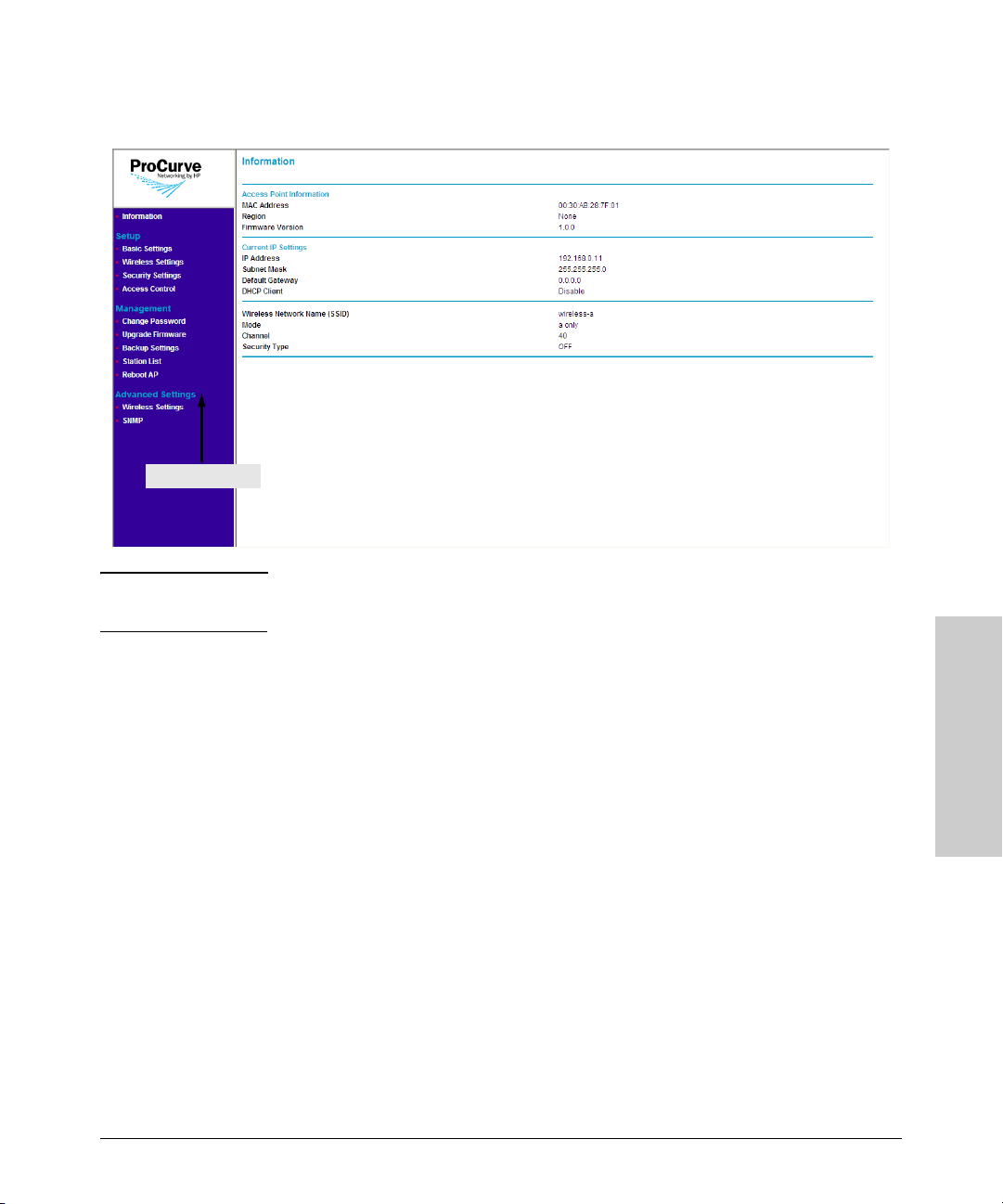
Figure 3-1. Information Page (Web Interface Home Page)
Menu
Note The Web interface does not have a Log Off button. To end your Web interface
session safely, HP recommends closing the Web browser.
Getting Started With Access
Navigating Around the Web Interface
The Web interface provides logical window groups for easy access to common
setup, management, and advanced configuration features. This section details
each of the logical window groups, submenus, screen elements and parameters. Cross-references are provided to any configuration procedures.
The Information sash is the first logical group available on the Web interface
menu. Clicking the Information menu Once accessed, it defaults to the Information window, also considered the Access Point 10ag home page.
3-3
Point Configuration
Page 34
Getting Started With Access Point Configuration
Introducing the Management Web Interface
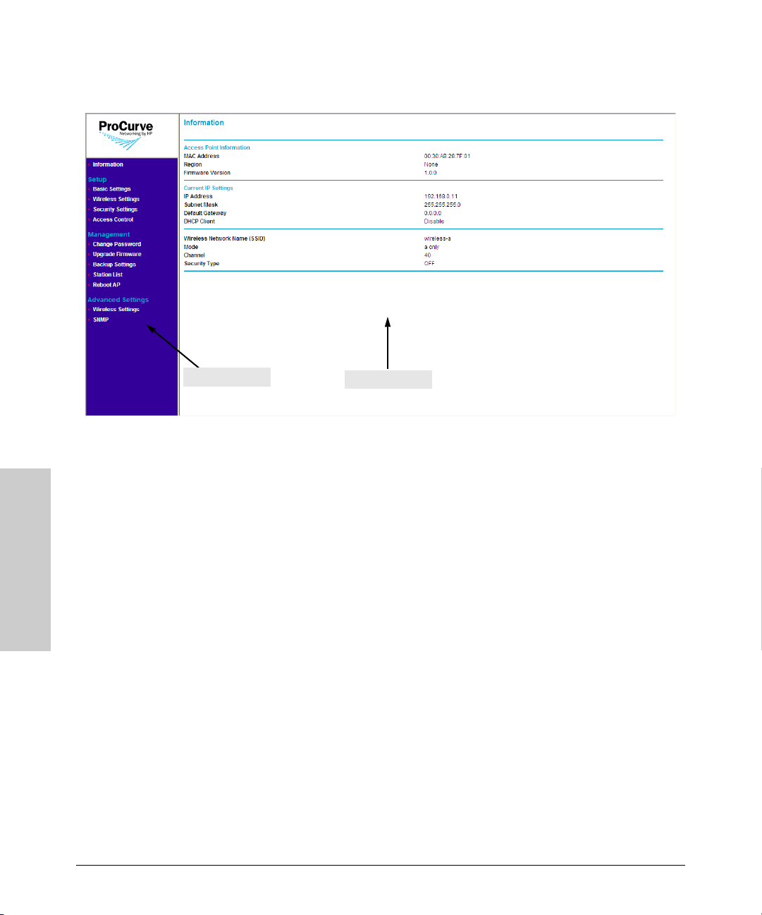
Figure 3-2. Web Interface Elements
Point Configuration
Getting Started With Access
Menu
Information Pane
The Web interface has two primary sections:
■ The menu: Located on the left-hand side of the page, the menu contains
links to the primary configuration options on the Web interface. Menu
items are grouped into four categories:
• Information (default home page): Shows information about the
access point, including the MAC address, firmware version, current
IP address settings, and configured wireless networks.
• Setup: Contains options for configuring the essential access point
settings, such as basic IP address settings, basic wireless settings,
security settings, and access control.
• Management: Contains options for performing administrative tasks
on the access point, including changing the password, uprading the
firmware, backing up and restoring settings, viewing the list of associated wireless stations, and rebooting the access point.
• Advanced Settings: Contains options for configuring advanced
wireless radio settings and changing the SNMP community names
used by the access point.
■ The information pane: Shows related configuration options for each
item on the menu. For example, if you click IP Settings on the menu, the
information pane loads the parameters that you can set or edit, and then
save for your desired configuration change to take effect.
3-4
Page 35

Getting Started With Access Point Configuration
Tasks for Your First Web Browser Interface Session
Tasks for Your First Web Browser
Interface Session
The first time you access the Web browser interface, there are a number of
basic tasks that you should perform. Table 3-1
specific instructions on the how perform the procedure, refer to the page
number listed in the right column.
In setting up your access point for network installation, this manual covers
many of the tasks that should be considered for proper security and management.
Each of these tasks are detailed in their respective sections, however, this
summary is provided as an aid for establishing your network.
Table 3-1. Basic Web Interface Tasks
To Learn How to Do This Task Refer to
Change the default password “Changing the Management Password” on page 5-3
lists these essential tasks. For
Set the correct country code “Configuring Basic Settings” on page 4-1
Control access to the wireless network “Controlling Access to the Wireless Network” on
page 4-22
Setting WLAN security to utilize WPA/WPA2 “Configuring the Security Settings” on page 4-7
Default Configuration Parameters
Table 3-2 lists some of the default settings with which the access point is
configured, including the basic IP address and wireless configuration parameters. Information on how to update each parameter is provided later in this
guide.
Getting Started With Access
Point Configuration
3-5
Page 36

Getting Started With Access Point Configuration
Default Configuration Parameters
Table 3-2.
Parameter Default Description
Username admin The name of the manager.
Password password The password for the manager.
IP Address 192.168.1.11 IP address compatible with your network.
Subnet Mask 255.255.255.0 Subnet mask compatible with your network.
Point Configuration
Getting Started With Access
Default Gateway not set IP address of the next-hop gateway node for network traffic that needs
Radio 1 Mode 802.11g The operating mode for Radio 1.
Radio 2 Mode 802.11a The operating mode for Radio 2.
SSIDs wireless-g - SSID 1
wireless-a - SSID 2
Note: The IP address and subnet mask assigned to the access point must be compatible with the IP addressing used
on your network. For more information on IP addressing, see “
to be able to reach off-subnet destinations.
The Service Set Identifier (SSID) for the access point interface, which
is broadcast in the beacon frames.
Configuring Basic Settings” on page 4-1.
3-6
Page 37

Setting Up the Access Point
This chapter provides information on how configure the access point’s
network, wireless, and security settings to ensure its proper operation on the
network. It also describes how to configure advanced options, such as the
wireless radio settings and the built-in SNMP agent.
Topics discussed in this chapter include:
■ Configuring Basic Settings
■ Configuring Basic Wireless Settings
■ Configuring the Security Settings
■ Controlling Access to the Wireless Network
■ Configuring Advanced Wireless Settings
4
Configuring Basic Settings
Basic settings refer to the IP address settings and the country code assigned
to the access point. Configuring the access point with an IP address The
procedure for configuring your access point's IP settings depends on the
network mode that you have selected.
Note If the access point's IP address settings are already compatible with your
network, you do not need to change them.
Setting Up the Access Point
4-1
Page 38
Setting Up the Access Point
Configuring Basic Settings
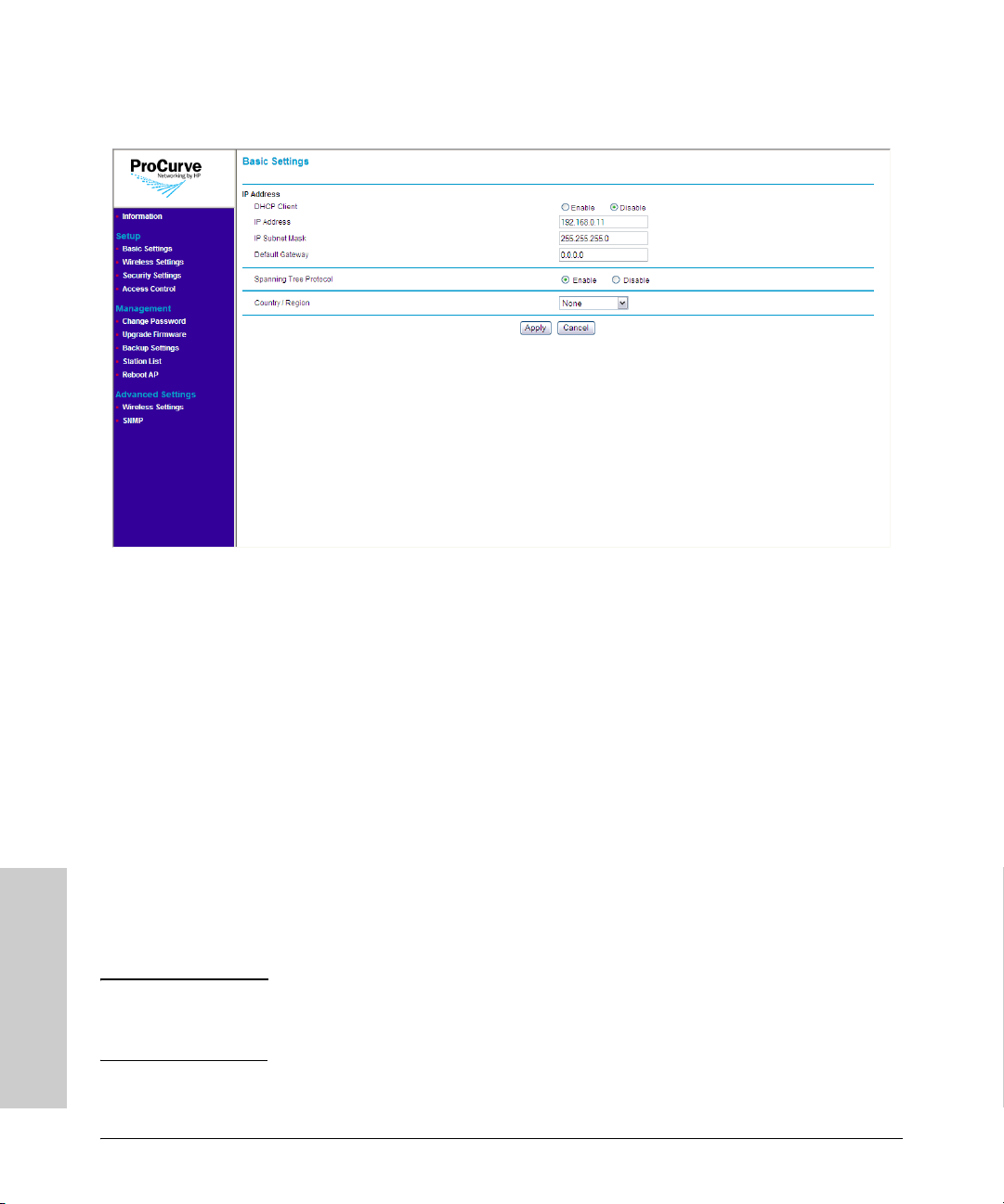
Figure 4-1. Basic Settings Page
To configure the access point’s basic settings:
1. On the menu, click Basic Settings.
2. Configure the IP address settings.
• Assign an IP address (recommended) – If you want to assign a fixed
IP address to the access point, select Disable in DHCP Client, and
then enter the IP Address, IP Subnet Mask, and Default Gateway that
you want to assign to it. These settings must be compatible with your
network to ensure that the access point can communicate with other
network devices.
• Enable the built-in DHCP client – If you have a DHCP server on the
network and you want the access point to automatically obtain an IP
address from the DHCP server, click Enable in DHCP Client. You do
not have to configure other settings, but you will need to check the
DHCP server from time to time to determine the IP address that the
access point is using. You need this IP address to connect to the Web
interface.
Note If you enable the built-in DHCP client and the access point fails to obtain an
IP address from the DHCP server (for example, the DHCP server is unreachable), the access point will automatically use 192.168.1.11, its default IP address.
Setting Up the Access Point
4-2
Page 39

Setting Up the Access Point
Configuring Basic Wireless Settings
3. If your network requires network devices to support the Spanning Tree
Protocol (for example, if your network requires STP for redundancy),
select the Enable button.
4. In Country/Region, select the country or region where you are installing
the access point (if you have not done so earlier).
Notes ■ The Country/Region option is unavailable in Access Point 10ag NA. The
country is fixed to USA.
■ If you are using Access Point 10ag WW, you must select the correct
country/region for the location in which you operate the access point, so
that it uses the correct authorized radio channels for wireless network
devices.
■ The radios are disabled if the Country/Region option is not set. Once this
option is configured, the radios can be enabled.
■ When resetting to factory defaults, the Access Point 10ag WW unit must
have its Country/Region setting configured. The Access Point 10ag NA will
be set to USA.
5. Click Apply.
Configuring Basic Wireless Settings
Basic wireless settings define the SSID, wireless channel, wireless mode, and
data rate that each wireless interface uses. Each SSID or The access point
comes with one predefined wireless profile (SSID wireless-a), which allows
802.11a wireless clients to associate with it. You can edit this existing wireless
profile, or you can create a new one.
4-3
Setting Up the Access Point
Page 40
Setting Up the Access Point
Configuring Basic Wireless Settings
Figure 4-2. Basic Wireless Settings Page
Creating a Wireless Profile
Note The access point ships with one preconfigured wireless profile for 802.11a.
You can create up to 8
Setting Up the Access Point
4-4
Page 41
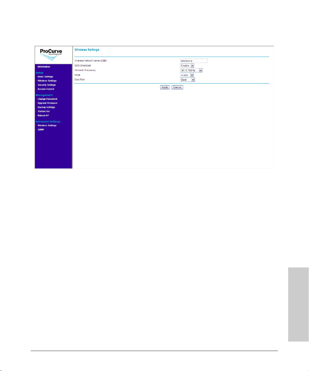
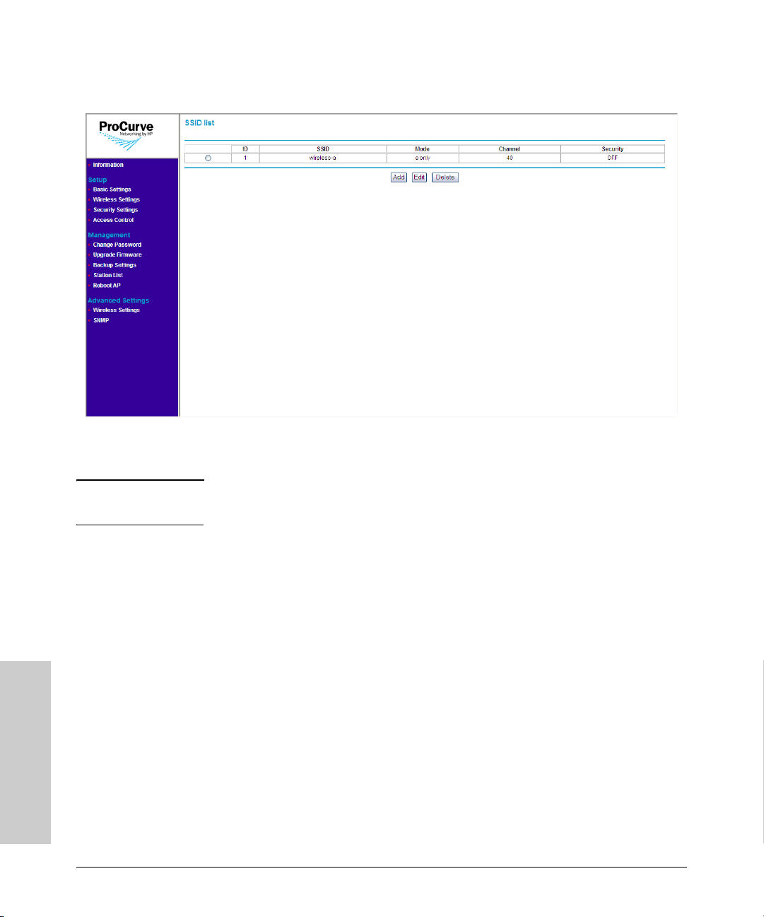
Figure 4-3. Add Wireless Profile Page
To create a new wireless profile:
Setting Up the Access Point
Configuring Basic Wireless Settings
1. On the menu, click Wireless Settings under Setup. The SSID List page
appears.
2. Click Add. The Wireless Settings page appears.
3. In Wireless Network Name (SSID), type a unique SSID (not used on
your network) that you want to assign to the wireless profile.
4. In SSID Broadcast, select Enable if you want to allow all wireless
stations within the range of the access point to see the SSID. Otherwise,
click Disable.
5. In Mode, select the wireless mode that you want this wireless profile to
use. Available options include:
• g and b: Select to allow connections from 802.11g and 802.11b clients
only.
• a: Select to allow connections from 802.11a clients only.
6. In Channel/Frequency, select the wireless channel and frequency that
you want this wireless profile to use. The range of channels and frequencies available depends on the wireless mode that you selected.
Setting Up the Access Point
4-5
Page 42

Setting Up the Access Point
Configuring Basic Wireless Settings
7. In Data Rate, select the maximum speed at which the access point can
transmit traffic for this wireless profile. If you want the access point to
automatically use the optimum data rate for the associated wireless
stations, select Best.
8. Click Apply. A confirmation message appears.
9. Click OK to finish creating the wireless profile.
Editing a Wireless Profile
To edit an existing wireless profile:
1. On the menu, click Wireless Settings under Setup.
2. Click the option button for the wireless profile that you want to edit. For
example, if you want to edit the wireless-a profile, click the option button
next to it.
3. Click Edit.
4. Modify the following settings as required:
• Wireless Network Name (SSID)
• SSID Broadcast
• Channel/Frequency
• Mode
• Data Rate
5. Click Apply.
Deleting a Wireless Profile
To delete a wireless profile:
1. On the menu, click Wireless Settings under Setup. The SSID List page
appears.
2. Select the option button for the wireless profile that you want to delete.
3. Click Delete.
The message Please wait... appears. After a few seconds, the SSID List
refreshes and the wireless profile you chose to delete disappears from the list
of SSIDs.
Setting Up the Access Point
4-6
Page 43

Setting Up the Access Point
Configuring the Security Settings
Configuring the Security Settings
Unlike wired networks, anyone with a compatible wireless card can receive
your wireless data transmissions well beyond your walls. Operating an unsecured wireless network creates an opportunity for outsiders to eavesdrop on
your network traffic or to enter your network to access your computers and
files. For this reason, use the security features of your wireless equipment.
Deploy the security features appropriate to your needs.
Figure 4-4. Security Settings Page
Wireless Security Overview
By default, the access point is configured as an “open system,” with no
security. This means that the access point broadcasts a beacon frame advertising each configured wireless network (SSID). If a wireless client has a
configured WLAN of "any," it can read the SSID from the beacon and use it to
allow immediate connection to the access point. Client stations are permitted
to connect with the access point without first verifying that users are authorized to access the network.
4-7
Setting Up the Access Point
Page 44

In addition, user data is transmitted over the air without being encrypted, and
is subject to being intercepted by client stations anywhere within range that
want to eavesdrop on the wireless network.
Wireless network security requires attention to three main areas:
■ Authentication: Verifying that stations attempting to connect to the
network are authorized users before granting access to the network.
■ Encryption: Encrypting data that passes between the access point and
stations (to protect against interception and eavesdropping).
■ Key Management: Assigning unique data encryption keys to each wire-
less station session, and periodically changing the encryption keys to
minimize risk of their potential discovery.
Authentication
The two ways of authenticating users on the Access Point 10ag are:
■ MAC Authentication: Based on the user's wireless station MAC address.
■ 802.1X Authentication: Based on the user credentials, such as; username/
password, digital certificates, etc.
MAC Authentication. MAC authentication of users can be done either
using a remote authentication server like a RADIUS server or by creating a
local database on the access point itself. MAC authentication is not as secure
as 802.1X authentication, as it is easy to decipher and spoof for unauthorized
network access.
802.1X Authentication. User 802.1X authentication can be implemented
either using a remote authentication server, such as a RADIUS server or by
using the local built-in RADIUS server on the access point itself. The user's
credentials are exchanged with the servers (both remote and local built-in)
using a mechanism called “Extensible Authentication Protocol (EAP)”. EAP
is a public-key encryption system to ensure that only authorized network users
can access the network. In wireless communications using EAP, a user
requests connection to a WLAN through an access point, which then requests
the identity of the user and transmits that identity to an authentication server
such as RADIUS. The server asks the access point for proof of identity, which
the access point gets from the user and sends back to the server to complete
the authentication. Local built-in RADIUS server supports only one EAP type
- PEAP-MSCHAPv2. For remote server authentication, the access point serves
as an intermediate authenticator to transparently pass any EAP type to the
remote server as specified in RFC3748.
Page 45

Setting Up the Access Point
Configuring the Security Settings
The Access Point 10ag supports all EAP type tested by the WiFi Alliance; TLS,
TTLS, PEAP0/MSCHAPv2, PEAP1/GTC and SIM. EAP types which do not
provide key management (like MD5) are not suitable for wireless networks.
802.1X authentication can be used with WEP, TKIP and AES encryption
ciphers. It is possible to use a combination of both MAC authentication and
802.1X authentication simultaneously on the same WLAN.
Encryption
The access point supports three types of encryption:
■ Wired Equivalent Privacy (WEP): Key lengths of 64 bits and 128 bits are
possible. WEP provides the least secure method of encryption (static WEP
is not secure, as it can be easily compromised).
■ Temporal Key Integrity Protocol (TKIP): Intermediate security between
WEP and AES with key length of 256 bits. Provides a more-secure method
of encryption than WEP (security is much better than WEP, but not as
robust as AES).
■ Advanced Encryption Standard (AES): AES is a symmetric 128-bit block
data encryption technique that works on multiple layers of the network.
It is the most effective encryption system currently available for wireless
networks.
Key Management
Keys for encrypting the data can be managed either dynamically using 802.1X
authentication or statically using pre-shared keys between the access point
and station. Dynamic key management provides significantly better security
when compared to using static keys.
4-9
Setting Up the Access Point
Page 46

Setting Up the Access Point
Configuring the Security Settings
Deciding Which Security Profile to Use
Table 4-1 shows a summary of available security profiles. Use this table as a
reference when deciding on which security profile best suits your network.
Remember that certain security profiles may require additional software or
hardware. 802.1X, for example, requires a RADIUS server to be configured on
the network. Additionally, not all wireless network cards support WPA.
Choose a security profile that provides the highest level of security while
maintaining compatibility with most, if not all, existing wireless devices on
the network.
Table 4-1. Summary of Wireless Security
Security Profile Client Support Implementation Considerations
None
(NOT RECOMMENDED)
WEP Built-in support on all 802.11a,
WPA-PSK (TKIP) •
WPA2-PSK (AES) •
WPA-PSK (TKIP) /
WPA2-PSK (AES)
WPA (TKIP) •
WPA2 (AES) •
802.1X •
Built-in support on all 802.11a,
802.11b, and 802.11g devices
802.11b, and 802.11g devices
No key management, data encryption, or user
authentication is used
• Provides only weak security
• Requires manual key management
•
When you have decided on which security profile to implement on your
network, refer to the next section, ”
Configuring the Access Point with Your
Preferred Security Profile”, for more details including the configuration proce-
dures.
Configuring the Access Point with Your Preferred Security Profile
Wireless security options are available on the Security Settings page. By
default, the Security Settings page shows None as the selected security
profile. When you click other security options, the page refreshes, and then
Setting Up the Access Point
displays additional options for that security profile.
4-10
Page 47

Setting Up the Access Point
Configuring the Security Settings
Note The security profile for each SSID must be set separately. For example, if you
set wireless-a to use WPA2, it will only be be applied to wireless-a. If you want
other SSIDs to use WPA2 as well, you need to configure each one separately.
Caution! When access point configuration parameters are changed, wireless stations
may be temporarily disconnected until the new configuration parameter is
enabled. This includes any changes to a WLAN or radio parameter.
Using No Security
No security mode transmits data over the wireless connection without any
form of encryption for data privacy. This mode may be appropriate for
systems that provide simple internet and printer access, as on a guest network.
It may also be appropriate where additional security is provided by the use of
encrypted VPN tunnels between the wireless client device and a network VPN
server. If this mode is used, it may be desirable to prevent advertising availability of the network to other stations by configuring the WLAN for closedsystem operation.
C a u t i o n! Use this mode on a sensitive internal network only for: initial setup, testing,
or problem solving; or where VPN connections are mandated to provide endtoend security for the otherwise insecure wireless connection.
4-11
Setting Up the Access Point
Page 48

Setting Up the Access Point
Configuring the Security Settings
Figure 4-5. No Security (Default) Page
To use no security (not recommended):
1. On the menu, click Security Settings. The Security Settings page
appears.
2. In SSID, select the SSID for which you want to set the security profile.
3. Under Security Options, click None.
4. Click Apply to save your changes.
Repeat this procedure for every SSID that you want to use no security.
Configuring WEP
Wired Equivalent Privacy (WEP) provides a basic level of security, preventing
unauthorized access to the network and encrypting data transmitted between
wireless clients and the access point. WEP uses static shared keys (fixedlength alphanumeric strings) that are manually distributed to all clients that
want to use the network.
Setting Up the Access Point
4-12
Page 49

Setting Up the Access Point
Configuring the Security Settings
Caution! WEP has been found to be seriously flawed and is not be recommended for
a high level of network security. For more robust wireless security, the access
point provides Wi-Fi Protected Access (WPA or WPA2) for improved data
encryption and user authentication.
Figure 4-6. WEP Options
To use WEP:
1. On the menu, click Security Settings. The Security Settings page
appears.
2. In SSID, select the SSID for which you want to set the security profile.
3. Under Security Options, click WEP.
4. Under Security Encryption (WEP), configure the authentication type
and encryption strength.
• Authentication: Select Open System to allow association of wireless stations without requiring authentication. Select Shared Key to
establish a rudimentary form of user authentication. Select Auto-
matic if Shared Key authentication is to be supported, but not
required. Default is Automatic.
4-13
Setting Up the Access Point
Page 50

Setting Up the Access Point
Configuring the Security Settings
Caution! Shared Key mode is seriously flawed, in that it utilizes the static WEP encryp-
tion key (transmitted openly) for station authentication. This allows the WEP
encryption key to be easily discovered by anyone who might eavesdrop on the
wireless network. If static WEP is configured, it is recommended to select
Open System authentication.
• Encryption Strength: Set the length of the encryption key that will
be used. Select 64 bits or 128 bits. Note that the same size of
encryption key must be supported on all wireless stations. Default is
64 bits. 56tgb uh ik/
5. Under Security Encryption (WEP) Key, enter up to four strings of
character keys. The number of characters required updates automatically
based on how you set Authentication and Encryption Strength.
6. Click Apply to save your changes.
Configuring WPA-PSK (TKIP)
Wi-Fi Protected Access (WPA) is an early version of the 802.11i security
standard. Temporal key integrity protocol (TKIP) is designed for WPA to
enhance WEP.
WPA-PSK (TKIP) employs a pre-shared key (PSK), which is used for an initial
check of credentials and a 128-bit "temporal key", which combines the
station’s MAC address and a 16-octet initialization vector to produce the
encryption key. This ensures unique key encryption. TKIP uses RC4 to
perform the encryption and changes temporal keys every 10,000 packets and
distributes them, thereby greatly improving the security of the network.
To use this security profile, your wireless stations must support WPA.
Note If your wireless network has a mix of stations, some support WPA2 and others
support the original WPA, HP recommends using WPA-PSK (TKIP)/WPA2PSK (AES). Refer to “
page 4-16
Setting Up the Access Point
for more information.
Configuring WPA-PSK (TKIP) / WPA2-PSK (AES)” on
4-14
Page 51

Figure 4-7. WPA-PSK (TKIP) Options
To use WPA-PSK (TKIP):
Setting Up the Access Point
Configuring the Security Settings
1. On the menu, click Security Settings. The Security Settings page
appears.
2. In SSID, select the SSID for which you want to set the security profile.
3. Under Security Options, click WPA-PSK (TKIP).
4. In the Password Phrase box under Security Options (WPA-PSK), enter
a string of at least 8 characters to a maximum of 63 characters. The string
that you enter here will be used as the shared secret key for WPA-PSK.
5. Click Apply to save your changes.
Configuring WPA2-PSK (AES)
WPA2-PSK (AES) employs a pre-shared key (PSK), which is used for an initial
check of credentials, and CCMP, an IEEE802.1X encryption method that uses
the Advanced Encryption Algorithm (AES).
To use this security profile, your wireless stations must support WPA.
Setting Up the Access Point
4-15
Page 52
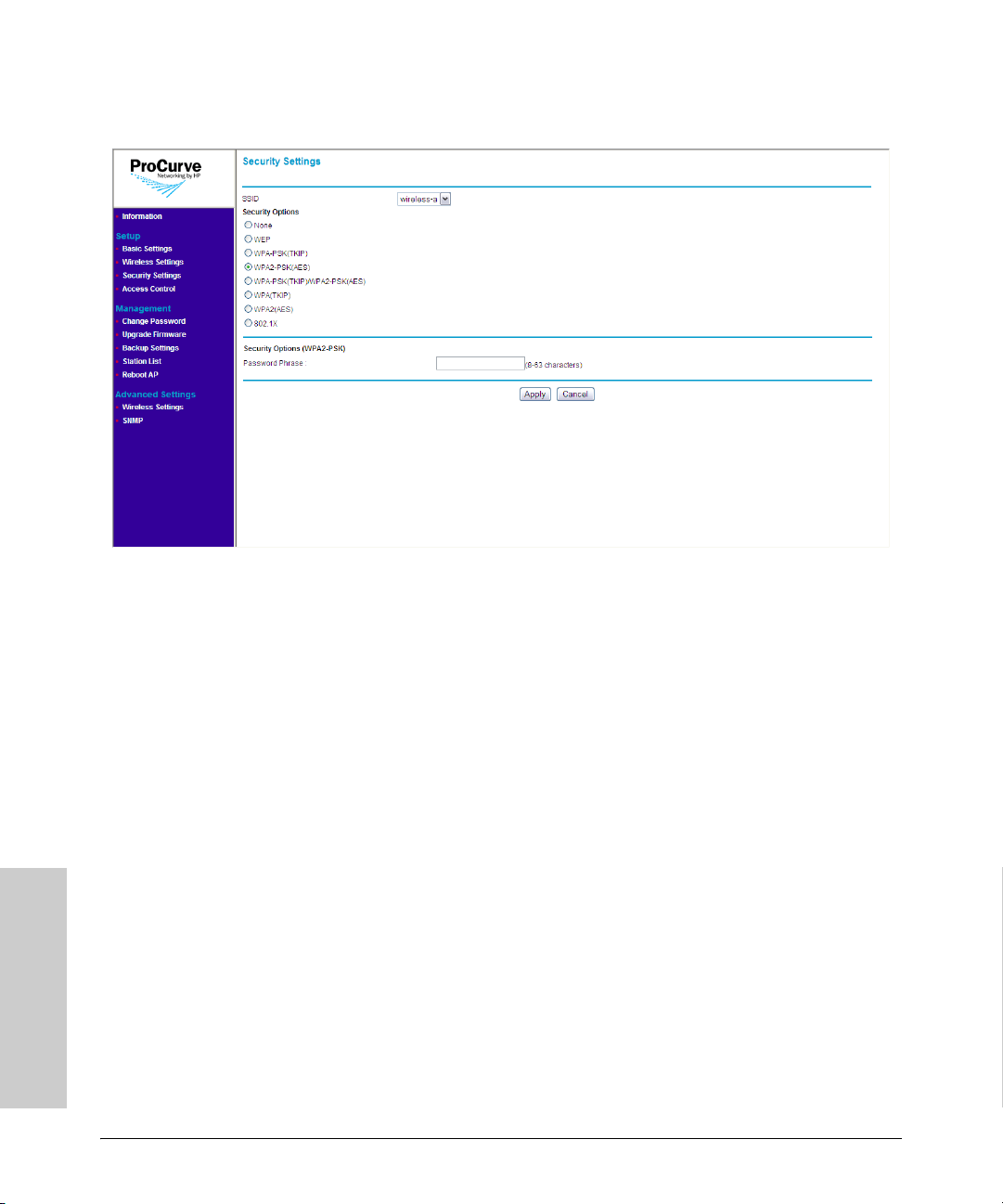
Setting Up the Access Point
Configuring the Security Settings
Figure 4-8. WPA2-PSK (AES) Options
To use WPA2-PSK (AES):
1. On the menu, click Security Settings. The Security Settings page
appears.
2. In SSID, select the SSID for which you want to set the security profile.
3. Under Security Options, click WPA2-PSK (AES).
4. In the Password Phrase box under Security Options (WPA-PSK), enter
a string of at least 8 characters to a maximum of 63 characters. The string
that you enter here will be used as the shared secret key for WPA-PSK.
5. Click Apply to save your changes.
Configuring WPA-PSK (TKIP) / WPA2-PSK (AES)
This security profile combines WPA-PSK (TKIP) and WPA2-PSK (AES). It uses
a pre-shared key (PSK), which is used for an initial check of credentials, and
a mixed cipher mode of TKIP and AES.
Setting Up the Access Point
4-16
Page 53

Configuring the Security Settings
Figure 4-9. WPA-PSK (TKIP) / WPA2-PSK (AES) Options
To use WPA-PSK (TKIP) / WPA2-PSK (AES):
Setting Up the Access Point
1. On the menu, click Security Settings. The Security Settings page
appears.
2. In SSID, select the SSID for which you want to set the security profile.
3. Under Security Options, click WPA-PSK (TKIP) / WPA2-PSK (AES).
4. In the Password Phrase box under Security Options (WPA-PSK), enter
a string of at least 8 characters to a maximum of 63 characters. The string
that you enter here will be used as the shared secret key for WPA-PSK.
1. Click Apply to save your changes.
Setting Up the Access Point
4-17
Page 54

Setting Up the Access Point
Configuring the Security Settings
Configuring WPA (TKIP)
This security profile uses TKIP as the encryption cipher and 802.1X as the
authentication mechanism. In this way, each station is going to utilize a unique
master key to derive the encryption between the access point and station.
Figure 4-10. WPA (TKIP) Options
To use WPA (TKIP):
1. On the menu, click Security Settings. The Security Settings page
appears.
2. In SSID, select the SSID for which you want to set the security profile.
3. Under Security Options, click WPA (TKIP).
4. In the Key Update Interval box, define the time interval (in seconds)
for regenerating a group key.
5. Under RADIUS Server, configure the RADIUS server settings:
• RADIUS Server IP: Type the IP address of the RADIUS server on
the network.
• RADIUS Port: Type the User Datagram Protocol (UDP) port number
used by the RADIUS server for accounting messages. Setting the port
number to zero disables RADIUS authentication.
Setting Up the Access Point
4-18
Page 55

Setting Up the Access Point
Configuring the Security Settings
• RADIUS Secret: Type a shared text string used to encrypt messages
between the access point and the RADIUS server. Make sure that the
same text string is specified on the RADIUS Accounting server. Do
not use blank spaces in the string. (Maximum length: 20 characters)
6. Click Apply to save your changes.
Repeat the same procedure for each SSID to which you want to assign WPA
(TKIP) as its security profile.
4-19
Setting Up the Access Point
Page 56
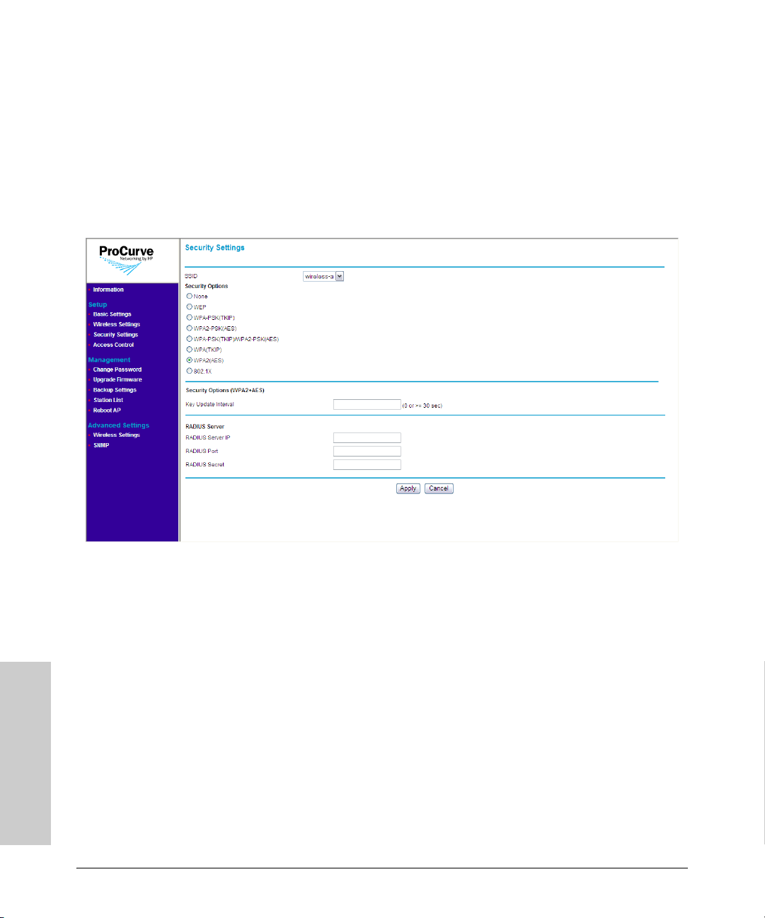
Setting Up the Access Point
Configuring the Security Settings
Configuring WPA2 (AES)
This security profile uses AES as the encryption cipher and 802.1X as the
authentication mechanism. In this way, each station is assigned a unique
master key to derive the encryption between the access point and station, and
the encryption keys can be automatically and periodically changed to further
reduce the possibility of their discovery.
Figure 4-11. WPA2 (AES) Options
To use WPA2 (AES):
1. On the menu, click Security Settings. The Security Settings page
appears.
2. In SSID, select the SSID for which you want to set the security profile.
3. In the Key Update Interval box, define the time interval (in seconds)
for regenerating a group key.
4. Under RADIUS Server, configure the RADIUS server settings:
• RADIUS Server IP: Type the IP address of the RADIUS server on
the network.
• RADIUS Port: Type the User Datagram Protocol (UDP) port number
used by the RADIUS server for accounting messages. Setting the port
number to zero disables RADIUS authentication.
Setting Up the Access Point
4-20
Page 57

Setting Up the Access Point
Configuring the Security Settings
• RADIUS Secret: Type a shared text string used to encrypt messages
between the access point and the RADIUS server. Make sure that the
same text string is specified on the RADIUS Accounting server. Do
not use blank spaces in the string. (Maximum length: 20 characters)
5. Click Apply to save your changes.
Repeat the same procedure for each SSID to which you want to assign WPA2
(AES) as its security profile.
Configuring 802.1X
802.1X is a standard frame-work for network access control that uses a central
RADIUS server for user authentication. This control feature prevents unauthorized access to the network by requiring an 802.1X client application to
submit user credentials for authentication.
The 802.1X standard uses the Extensible Authentication Protocol(EAP) to
pass user credentials (either digital certificates, usernames and passwords, or
other) from the client to the RADIUS server. Client authentication is then
verified on the RADIUS server before the access point grants client access to
the network.
Figure 4-12. 802.1X Options
4-21
Setting Up the Access Point
Page 58

Setting Up the Access Point
Controlling Access to the Wireless Network
To use 802.1X:
1. On the menu, click Security Settings. The Security Settings page
appears.
2. In SSID, select the SSID for which you want to set the security profile.
3. Under Security Options, click 8021.x.
4. Under Security Options (802.1X), configure the RADIUS server settings:
• RADIUS Server IP: Type the IP address of the RADIUS server on
the network.
• RADIUS Port: Type the User Datagram Protocol (UDP) port number
used by the RADIUS server for accounting messages. Setting the port
number to zero disables RADIUS authentication.
• RADIUS Secret: Type a shared text string used to encrypt messages
between the access point and the RADIUS server. Make sure that the
same text string is specified on the RADIUS Accounting server. Do
not use blank spaces in the string. (Maximum length: 20 characters)
5. Click Apply to save your changes.
Repeat the same procedure for each SSID to which you want to assign 802.1X
as its security profile.
Controlling Access to the Wireless
Network
You can configure the access point to authenticate client MAC addresses
against a database stored locally on the access point or remotely on a RADIUS
server. Client MAC addresses on the local database can be specified as allowed
or blocked access the network. This enables the access point to control which
devices can associate with the access point.
Note Access control settings for each SSID/wireless interface need to be configured
individually. Enabling access control for one SSID will not enable access
control for the other.
Setting Up the Access Point
4-22
Page 59

Controlling Access to the Wireless Network
Setting Up the Access Point
Figure 4-13. Access Control Page
There are two options for setting up access control on the wireless network:
■ Local MAC authentication, and
■ Remote MAC authentication
Note You can only use one type of MAC authentication at any given time. When
both local and remote MAC authentication are enabled and configured, local
MAC authentication will override remote MAC authentication.
Before setting up either type of MAC authentication, you will need to list down
the MAC addresses of the wireless stations that you want to allow or block.
Setting Up Local MAC Authentication
Local MAC authentication allows you to add entries to the built-in MAC
authentication database and to take certain actions based on a wireless
client’s MAC address. The MAC list can be configured to allow or deny
network access to specific clients.
Note You can add up to 16 MAC addresses to the local MAC authentication
database.
4-23
Setting Up the Access Point
Page 60

Setting Up the Access Point
Controlling Access to the Wireless Network
To configure local MAC authentication:
1. On the menu, click Access Control.
2. In SSID, select the SSID to which you want allow the wireless station
access.
3. In MAC Authentication, select Local.
4. In Access Control, select the access option that you want to configure
for the wireless station. Options include:
• Disable: Click to disable MAC authentication. Selecting this option
will disable both local and remote MAC authentication. After clicking
Disable, click Apply to save your changes. You do not need to
configure other settings.
• Allow: Click to permit access to all MAC addresses except those
listed on the local database as “block.”
• Block: Click to deny access to all MAC addresses except those listed
on the local database as “allowed.”
5. In the MAC Address box, enter the MAC or physical address of the
wireless station that you want to allow or block. A MAC address consists
of six pairs of alphanumeric characters, for example, 00 11 AA 22 BB 33.
6. Click Add. The page refreshes and the MAC address that you entered
appears under MAC Address List.
Repeat steps 5 to 6 for each wireless station that you want to allow or
block.
7. Click Apply.
The message Please wait... appears as the address is added to the list. When
the access point has completed the process, the MAC address appears in the
MAC Address List table.
To delete a MAC address from the list, click the Delete button next to it.
Setting Up the Access Point
4-24
Page 61
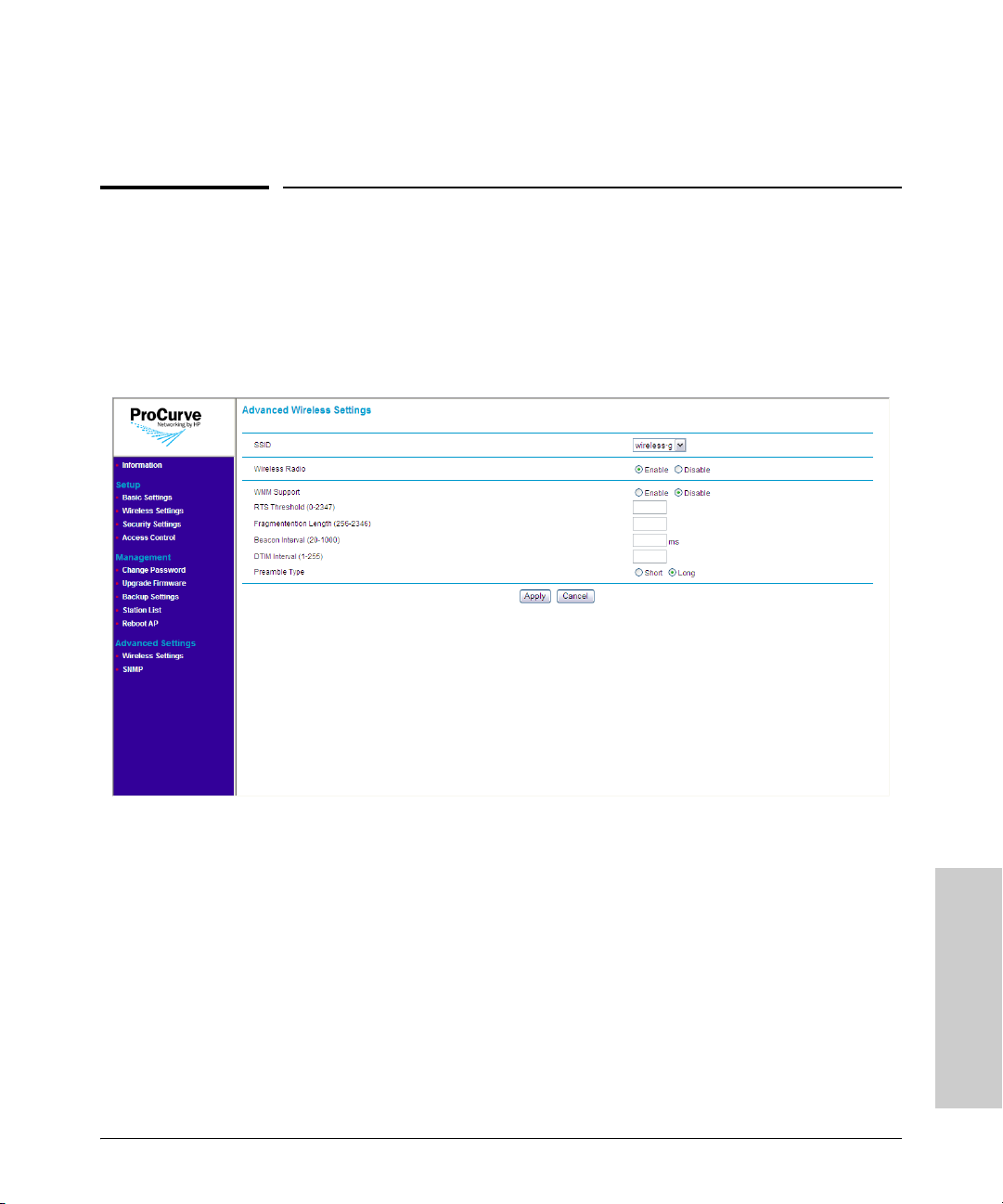
Configuring Advanced Wireless Settings
Setting Up the Access Point
Setting Up Remote MAC Authentication
Configuring Advanced Wireless Settings
Advanced wireless settings include options for enabling and disabling the
wireless radios and Wi-Fi Multimedia (WMM). Options for fine tuning the
access point’s radio operation are also available.
Figure 4-14. Advanced Wireless Settings Page
To configure the advanced wireless settings:
1. On the menu, click Wireless Settings under Advanced Settings.
2. In SSID, select the SSID for which you want configure the advanced
wireless settings.
3. In WMM Support, click Enable if you want the access point to prioritize
certain types of traffic above other traffic. When enabled, WiFi Multimedia
(WMM) provides basic Quality of Service (QoS) to wireless network. HP
recommends enabling this option if your network requires prioritization
for voice or video traffic (for example, if network users use Voice over IP
applications).
4-25
Setting Up the Access Point
Page 62

Setting Up the Access Point
Configuring Advanced Wireless Settings
4. Configure the following advanced wireless settings for the SSID that you
selected:
• RTS Threshold: Sets the packet size threshold at which a Request
to Send (RTS) signal must be sent to a receiving station prior to the
sending station starting communications. The access point sends RTS
frames to a receiving station to negotiate the sending of a data frame.
After receiving an RTS frame, the station sends a CTS (clear to send)
frame to notify the sending station that it can start sending data.
(Default is 2347)
• Fragmentation Length: Configures the minimum packet size that
can be fragmented when passing through the access point. Fragmentation of the PDUs (Package Data Unit) can increase the reliability of
transmissions because it increases the probability of a successful
transmission due to smaller frame size. If there is significant interference present, or collisions due to high network utilization, try setting
the fragment size to send smaller fragments. This speeds the retransmission of smaller frames. It is more efficient to set the fragment size
larger if very little or no interference is present because it requires
overhead to send multiple frames. If set to 2346, this feature is
disabled. Range: 256-2346, even numbers. (Default is 2346)
• Beacon Interval: The rate at which beacon frames are transmitted
from the access point. The beacon frames allow wireless stations to
maintain contact with the access point. They may also carry powermanagement information. Range: 20-1000 ms (Default is 100)
• DTIM Interval: The Delivery Traffic Indication Message (DTIM)
interval helps keep marginal clients connected by sending "wake up"
frames. Range: 1- 255 (Default is 1).
• Preamble Type: Sets the length of the signal preamble used at the
start of a data transmission. Using a short preamble can increase data
throughput on the access point, but requires all associated stations
be able to support a short preamble. (Default is Long)
– Long: Sets the preamble to long. Using a long preamble ensures
– Short: Sets the preamble according to the capability of stations
the access point can support all 802.11b and 802.11g stations
that are currently associated. Uses a short preamble if all associated stations can support it, otherwise a long preamble is used.
5. Click Apply to save your changes
Setting Up the Access Point
4-26
Page 63

Setting the SNMP Community Names
Setting Up the Access Point
Setting the SNMP Community Names
You can manage the access point from a network management station running
a Simple Network Management Protocol (SNMP) management application,
such as ProCurve Manager.
The access point SNMP agent supports SNMP versions 1 and 2c. Management
access from SNMP v1 or v2c stations is controlled by community names. To
communicate with the access point, an SNMP v1 or v2c management station
must first submit a valid community name for authentication.
The default community names are public for read-only access and private for
read/write access. If you intend to support SNMP v1 or v2c managers, HP
recommends that you change the default community names to prevent unauthorized access.
Figure 4-15. SNMP Community Page
To change the default SNMP community names:
1. On the menu, click SNMP. The SNMP Community page appears.
2. To establish a public read-only SNMP community, type a name text string
to replace the default community name (public) in the Read Only text
field.
4-27
Setting Up the Access Point
Page 64

Setting Up the Access Point
Setting the SNMP Community Names
3. To establish a private read-write SNMP community, type a name text string
to replace the default community name (private) in the Read Write text
field.
4. Click Apply to save your changes and activate the new SNMP community
names.
Supported MIB Browsers
In addition to ProCurve Manager, you can also use third-party management
information base (MIB) browsers to manage the access point via SNMP. MIB
browsers such as Net-Snmp management tool (version 5.1.2) and SNMPc
Network Manager (version 7.0.18) are supported.
Setting Up the Access Point
4-28
Page 65

Managing the Access Point
This chapter describes management tasks that you may periodically perform,
including changing the management password and upgrading the firmware.
Topics discussed in this chapter include:
■ Viewing Device Information
■ Changing the Management Password
■ Upgrading the Firmware
■ Viewing the List of Associated Stations
■ Rebooting the Access Point
Viewing Device Information
5
Managing the Access Point
Device information is available on the Information page, which is the default
home page that loads after you log on to the Web interface. To access the
Information page when you are already logged on, click Information on the
menu.
5-1
Page 66
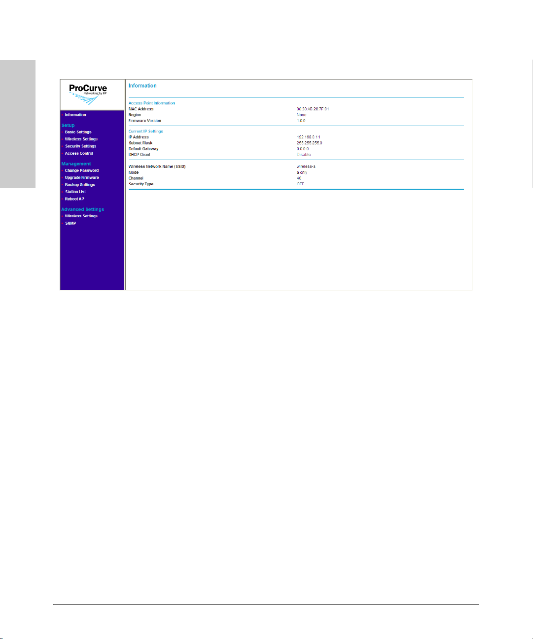
Managing the Access Point
Viewing Device Information
Figure 5-1. Information Page
Managing the Access Point
The Information page displays three types of device information:
■ Access Point Information
• MAC Address: The physical layer address for the Ethernet port
interface
• Region: Shows the country/region that was set on the Basic Setting
page
• Firmware Version: Shows the version number for the runtime soft-
ware
■ Current IP Settings
• IP Address: Shows the IP address of the management interface for
this device
• Subnet Mask: Shows the subnet mask configured for the manage-
ment interface
• Default Gateway: Show the IP address of the next-hop gateway node
for network traffic that needs to be able to reach off-subnet destinations.Gateway address
• DHCP Client: Shows whether the built-in DHCP client is Enabled or
Disabled.
■ Wireless Network Information
• Wireless Network Name (SSID): SSID configured for this wireless
network
5-2
Page 67

Changing the Management Password
Managing the Access Point
• Mode: Shows the wireless mode in use, either g/b (802.11gb) or a
(802.11a)
• Channel: Shows the wireless channel on which the access point is
broadcasting signal.
• Security Type: Shows the security profile assigned to this wireless
interface.
Changing the Management Password
Management access to the Web interface is controlled through an administrator password. To prevent unauthorized users from accessing the Web
interface and modifying the Access Point's settings, the interface is passwordprotected.
The default manager user name is admin and the default password is password.
C a u t i o n HP strongly recommends that you change the default Web interface password
immediately after your first logon. This will help prevent unauthorized users
from logging on to the Web interface and changing the access point settings
to compromise your network.
Managing the Access Point
5-3
Page 68

Managing the Access Point
Changing the Management Password
Figure 5-2. Change Password Page
Managing the Access Point
To change the default Web interface password:
1. On the menu, click Change Password. The Change Password page
appears.
2. In Set Password, type your new password.
Note The password is case-sensitive and must be between 1 and 32 alphanu-
meric characters long.
3. In Repeat New Password, type your new password again to confirm.
4. In Restore Default Password, click No.
5. Click Apply to save your changes.
Your new password is instantly applied, and the he logon dialog box appears
after you save your new password. Enter your new password in the password
box to log back into the Web interface.
If You Forget Your Password
If you lose the password, you can reset it by pressing the Reset to Default
button on the back of the access point for one second to four seconds. This
action resets the password to the default factory password, which is password.
5-4
Page 69

Managing the Access Point
Upgrading the Firmware
Caution! Do NOT press the Reset to Default button for more than four (4) seconds.
Doing so will reset the access point to factory default configuration and erase
all your current access point configuration.
Upgrading the Firmware
The upgrade function allows you to install on the Access Point any new
firmware releases that may be made available. To install the new firmware,
you first need to download the firmware from the HP Web site to the management computer.
Before performing an upgrade, take note of the current firmware version
(shown on the Information page). You need to know this to be able to verify
that the upgrade has been completed successfully.
Where to Download Firmware Upgrades
The ProCurve support site periodically provides access point software
updates through the ProCurve Web site (http://www.procurve.com). Access
point software updates are made available on the ProCurve Networking Web
site, http://www.hp.com/go/hpprocurve under “product support > software
upgrades.”
Managing the Access Point
For more information, see the support and warranty booklet shipped with the
access point.
Upgrade Precautions
CAUTION! Here are a few things that you can do to ensure that the upgrade process will
be completed successfully:
■ Do not use your Web browser until the upgrade process has completed.
■ Do not interrupt the Web browser by closing the window, clicking a link,
or loading a new page.
■ Do not interrupt the firmware upload by turning off your computer or the
Access Point.
After an access point firmware update, the access point will automatically
reboot and apply the updated code.
5-5
Page 70
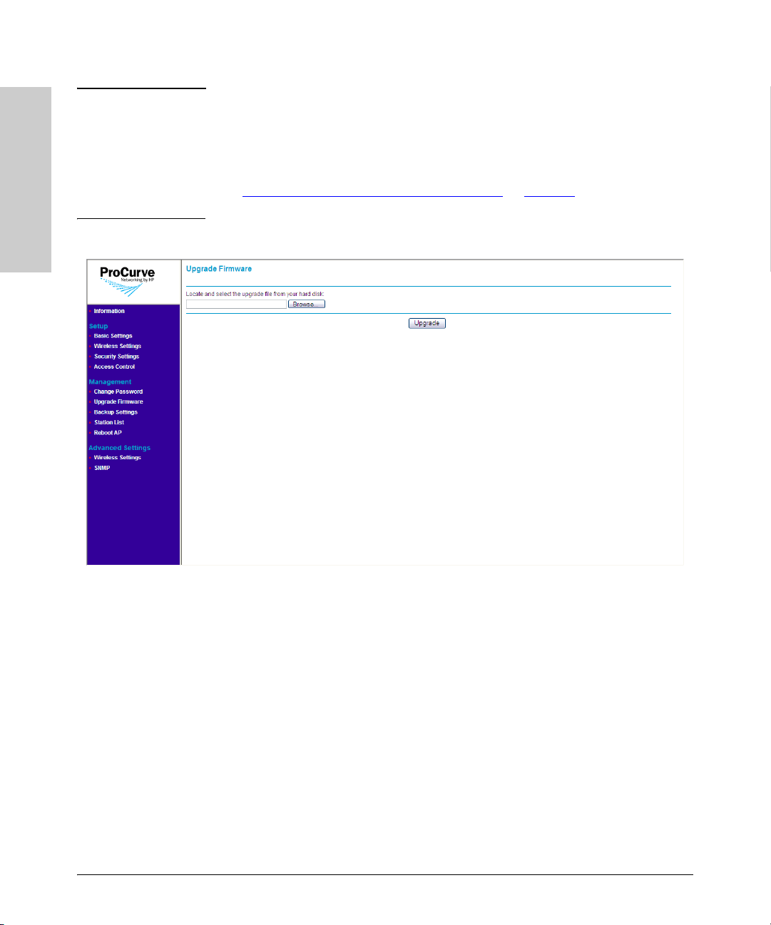
Managing the Access Point
Upgrading the Firmware
Note Upgrading the firmware will not change the current configuration of the
access point. The access point configuration is contained in a separate file
that can also be transferred, for example, for archive purposes or to be used
in another access point of the same model. It is recommended that you save
a copy of the configuration file before upgrading your access point software.
See “
Backing Up and Restoring Configuration” on page 5-8 for information on
saving the access point’s configuration file.
Figure 5-3. Upgrade Firmware Page
Managing the Access Point
5-6
Upgrade Procedure
To upgrade the access point firmware:
1. On the menu, click Upgrade Firmware. The Upgrade Firmware page
appears.
2. Click Browse. The Choose File dialog box appears.
3. Go to the folder where you saved the upgrade file, select the file, and then
click Open. The Choose File dialog box disappears.
4. Click Upgrade.
When the firmware update is complete, the Access Point reboots itself,
and then prompts you to log on to the Web interface again.
5. Log on to the Web interface.
Page 71
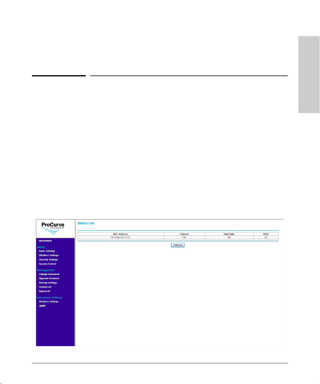
Viewing the List of Associated Stations
Managing the Access Point
6. On the menu, click Information.
7. Check the value for Firmware Version and verify that it shows a later
version than what was installed before the update.
Viewing the List of Associated Stations
You can view which wireless stations are associated with the access point
anytime by accessing the Station List page on the Web interface.
To access the page, click Station List on the menu. A table appears, which lists
the following information about each associated wireless station:
■ MAC address: Displays the MAC or physical address of the associated
wireless station
■ Channel: Displays the current channel on which the wireless station is
receiving broadcast signal
■ Data rate: Displays the transmission speed at which the wireless station
is receiving data from the access point
■ RSSI: Displays the received signal strength of the wireless station on the
current wireless channel
Figure 5-4. Station List Page
Managing the Access Point
5-7
Page 72

Managing the Access Point
Backing Up and Restoring Configuration
Backing Up and Restoring Configuration
To back up the current access point configuration:
1. On the menu, click Backup Settings. The Backup Settings page appears.
2. Click Backup under Save a Copy of Current Settings. A browser dialog
box appears, as your browser attempts to download the configuration file
Managing the Access Point
from the access point.
3. Click Save. The Save As dialog box appears.
4. Choose a location where to save the configuration file and, if you want,
change the file name. The default file name is HP500_POE_R.cfg. If you
are changing the file name, HP recommends including the current date in
the file name for ease of identification.
5. Click Save.
6. Start Windows Explorer, and then browse to the location where you save
the configuration file, and then verify that it has been downloaded
successfully.
To restore a backup configuration:
1. On the menu, click Backup Settings. The Backup Settings page appears.
2. Click Browse under Restore Saved Setting from a File.
3. When the Choose File dialog box appears, browse to the location where
you saved the backup configuration file.
4. Select the backup file (default file name is HP500_POE_R.cfg), and then
click Open.
5. Click Restore. A confirmation message appears.
Caution! Restoring settings from a backup configuration file will overwrite all current
access point settings. Make sure you are restoring the correct backup file.
5-8
Page 73

Managing the Access Point
Rebooting the Access Point
6. Click OK to restore settings from the backup file and overwrite the
current settings. The message Please wait... appears as the access point
restores the backup configuration file. When the access point has
completed the restore process, the following message appears:
AP is rebooting......
PLEASE WAIT until re-directed to Information page.
The browser page refreshes, and the Information page appears.
Rebooting the Access Point
If you feel that the Access Point is not operating normally, try rebooting the
device. This clears memory resources in use and can help restore normal
operation.
Note that rebooting the Access Point will temporarily disconnect any wireless
stations that are connected to it. If you have users on the network that are
connected to the Internet through the Access Point, they will be temporarily
disconnected. Their connection will be restored as soon as the Access Point
has completed rebooting.
Managing the Access Point
You can reboot the access point by pressing the Reset to Default button (on
the rear of the access) for one to three seconds. Alternatively, you can click
Reboot AP on the Web interface to perform the same action.
Refer to the procedure below for instructions on how to reboot the access
point from the Web interface.
5-9
Page 74

Managing the Access Point
Rebooting the Access Point
Figure 5-5. Reboot Page
Managing the Access Point
To reboot the Access Point:
1. On the menu, click Reboot AP.
2. In Reboot access point, click Yes.
3. Click Apply. A confirmation message appears.
4. Click OK. The following message appears:
AP is rebooting......
PLEASE WAIT until re-directed to Information page.
When the Access Point has rebooted, the logon dialog box appears.
5. Enter your user name and password to log back on to the Web interface.
5-10
Page 75

Troubleshooting
This chapter describes how to troubleshoot your ProCurve Wireless
Access Point 10ag. Note that this document describes troubleshooting mostly
from a hardware perspective.
This chapter describes the following:
■ Basic Troubleshooting Tips
■ Diagnosing with the LEDs
■ Hardware Diagnostic Tests
■ Restoring Factory Default Configuration
■ HP Customer Support Services
Basic Troubleshooting Tips
6
Troubleshooting
Most problems are caused by the following situations. Check for these items
first when starting your troubleshooting:
■ Connecting to devices that have a fixed full-duplex configuration.
By default, the RJ-45 port uses auto-negotiation to determine the duplex
mode. That is, when connecting to attached devices, the access point will
operate in one of two ways to determine the link speed and the communication mode (half duplex or full duplex):
• If the connected device is also configured to use auto-negotiation, the
access point will automatically negotiate both link speed and communication mode.
• If the connected device has a fixed configuration, for example
100 Mbps, at half or full duplex, the access point will automatically
sense the link speed, but will default to a communication mode of half
duplex.
Because the Access Point 10ag behaves in this way (in compliance with
the IEEE 802.3-2005 standard), if a device connected to the access point
has a fixed configuration at full duplex, the device will not connect
correctly to the access point. The result will be high error rates and very
inefficient communications between the access point and the device.
6-1
Page 76

Troubleshooting
Troubleshooting
Basic Troubleshooting Tips
All devices connected to the Access Point 10ag should be configured to
auto-negotiate. To correct this problem you have to manually set the
access point’s RJ-45 port to match the duplex mode used by the attached
device.
■ Faulty or loose cables. Look for loose or obviously faulty connections.
If the cables appear to be OK, make sure the connections are secure. If
that does not correct the problem, try a different cable.
■ Non-standard cables. Non-standard and miswired cables may cause
network collisions and other network problems, and can seriously impair
network performance. Use a new correctly-wired cable or compare your
cable to the cable in appendix Appendix B
, Access Point Port and Network
Cables for pinouts and correct cable wiring. A category 5 cable tester is a
recommended tool for every 100Base-TX network installation.
■ Improper network topologies. It is important to make sure you have a
valid network topology. Common topology faults include excessive cable
length and excessive repeater delays between end nodes. If you have
network problems after recent changes to the network, change back to
the previous topology. If you no longer experience the problems, the new
topology is probably at fault. Sample topologies are shown at the end of
Chapter 2
in this book, and some topology configuration guidelines can
be found online at the ProCurve Networking Web site,
http://www.hp.com/rnd/index.htm
under “network configuration examples.”
■ Mobile users cannot connect to the network. Make sure that the
access point and wireless stations are configured with compatible security settings. Check to ensure that the wireless station is within the
maximum range supported by the access point. Also verify that the
wireless station has been configured with an IP address compatible with
the attached network, either manually or via DHCP.
6-2
For more information on possible network problems and their solutions, refer
to the technical note “Troubleshooting LAN Performance and Intermittent
Connectivity Problems”, which can be found on the ProCurve Networking
Web site, http://www.hp.com/go/hpprocurve, in the Reference Library section
under http://www.hp.com/rnd/library/index.htm under “T” in the “A-Z
index.”
Page 77

Diagnosing with the LEDs
Troubleshooting
Diagnosing with the LEDs
Table 6-1 shows LED patterns on the access point that indicate problem
conditions.
1. Check in the table for the LED pattern that you see on your access point.
2. Refer to the corresponding diagnostic tip on the next few pages.
Table 6-1. LED Error Indicators
LED Pattern Indicating Problems
Power LED Radio LEDs LAN LED
Off with power cord plugged in * * 1
Off without power cord plugged in,
but linked to a PoE source
Prolonged on or off during
initialization
* This LED is not important for the diagnosis.
†
Initialization takes between 30 seconds and one minute after a power on or reset.
†
On Off * 4
On * Off with cable
On * On, but the port is not
Prolonged on or off
**2
Prolonged on or off
during
initialization
during initialization
†
communicating
connected
Diagnostic
†
Tips
3
5
6
Troubleshooting
6-3
Page 78

Troubleshooting
Diagnosing with the LEDs
Diagnostic Tips
Tip Problem Solution
Troubleshooting
1 The access point
is not plugged
into an active AC
power source, or
the access
point’s AC power
adapter may
have failed.
2 The access point
is not receiving
power from the
PoE source.
3 The access point
has experienced
a software
failure during
initialization.
1. Verify that the power cord is plugged into an active power source and to the access
point's AC power adapter. Make sure these connections are secure.
2. Try power-cycling the access point by unplugging and plugging the power cord back
in.
3. If the Power LED is still not on, verify that the AC power source works by plugging
another device into the outlet. Or try plugging the access point into a different outlet
or try a different power cord.
If the power source and power cord are OK and this condition persists, the access point’s
AC power adapter may have failed. Call your HP-authorized network reseller, or use the
electronic support services from HP to get assistance. See the Customer Support/
Warranty booklet for more information.
1. Verify that access point’s 10/100Base-TX port is attached to a PoE source device.
2. Verify that the PoE source device is powered on, and that the PoE function has been
administratively enabled on the source port attached to the access point.
3. Refer to Tip 6 to verify that the network cable is functioning properly.
After a power on or reset, the LEDs indicate stages of the system initialization. If there is
a software failure during initialization, the LED pattern indicates at which stage the failure
occurred. The normal LED sequence during initialization is as follows:
Stage 1. Power LED on for 5 seconds. System initialization has started.
Stage 2. LAN LED blinks 5 times in 1 second. The boot ROM has successfully initialized.
Stage 3. All LEDs on for 5 seconds. The operating system kernel has successfully loaded.
Stage 4. LAN LED on only. The operating system is mounting the file system.
Stage 5. LAN and 11a/b/g LEDs on. Radio drivers have been successfully loaded.
Stage 6. LAN, 11a/b/g, and 11b/g LEDs on. The access point software is initializing.
Stage 7. Normal LED operation. Initialization has completed successfully.
The entire initialization sequence takes between 30 seconds (normal reset) and one
minute (factory default reset). If one of the above LED patterns display longer than one
minute, a failure has occurred. Do the following:
1. Reset the access point by pressing the Reset button on the back of the access point,
or by power cycling the access point.
2. If the fault indication reoccurs, take note of the LED pattern and contact your HPauthorized network reseller, or use the electronic support services from HP to get
assistance. See the Customer Support/Warranty booklet for more information.
4 Wireless link has
been
administratively
disabled.
6-4
Verify that the wireless port has not been disabled through an access point configuration
change. You can use the Web browser interface to determine the state of the wireless
port and re-enable the port if necessary. Also verify that the country code has been set.
Page 79

Tip Problem Solution
Diagnosing with the LEDs
Troubleshooting
5 The
10/100Base-TX
network
connection is not
working
properly.
Try the following procedures:
• Verify that both ends of the cabling, at the access point and the connected device, are
connected properly.
• Verify the connected device and access point are both powered on and operating
correctly.
• Verify duplex operation (see page 6-1).
• If these procedures don’t resolve the problem, try using a different cable.
Troubleshooting
6-5
Page 80

Troubleshooting
Troubleshooting
Hardware Diagnostic Tests
Hardware Diagnostic Tests
Testing the Access Point by Resetting It
If you believe that the access point is not operating correctly, you can reset
the access point. To reset the access point, either
■ Unplug and plug in the power cord (power-cycling).
■ Press the Reset button on the back of the access point for about two
seconds (until the LEDs start to blink rapidly).
Caution If you press the Reset to Default button for five seconds or more, you will reset
the board and reload the factory default settings. See “
Default Configuration” on page 6-7.
Power-cycling the access point and pressing the Reset to Default button both
cause the access point to perform its system initialization, which normally
resolves any temporary operational problems.
Restoring Factory
Checking the Access Point’s LEDs
The system initialization is successful when the Power LED is on and the other
LEDs are in a normal operating state after approximately one minute. If the
LED pattern is different that this for longer than one minute, there may be a
problem with the access point.
See “
Diagnosing with the LEDs” on page 6-3 for information on interpreting
the LED patterns.
Testing Twisted-Pair Cabling
Network cables that fail to provide a link or provide an unreliable link between
the access point and the connected network device may not be compatible
with the IEEE 802.3 Type 10Base-T, or 100Base-TX standards. The twistedpair cables attached to the Access Point 10ag must be compatible with the
appropriate standards. To verify that your cable is compatible with these
standards, use a qualified cable test device.
6-6
Page 81

Restoring Factory Default Configuration
Troubleshooting
Testing Access Point-to-Device Network Communications
You can perform the following communication tests to verify that the network
is operating correctly between the access point and any connected device that
can respond correctly to the communication test.
■ Ping Test -- a network layer test used on IP networks that sends test
packets to any device identified by its IP address
Testing End-to-End Network Communications
Both the access point and the cabling can be tested by running an end-to-end
communications test -- a test that sends known data from one network device
to another through the access point. You can run a PING test to verify that the
entire communication path between the two network devices is functioning
correctly.
Restoring Factory Default Configuration
Troubleshooting
As part of your troubleshooting process on the Access Point 10ag, it may
become necessary to return the access point’s configuration to its factory
default settings. This process momentarily interrupts the access point’s operation and reboots the access point. When restoring the factory default configuration, all settings are cleared, including the Manager password and any IP
address.
Note Restoring factory defaults removes all access point configuration changes that
you have made from the factory default settings. This includes, for example,
IP addresses, and radio interface settings. Returning the configuration of these
features to their factory default settings may result in network connectivity
issues.
If the access point has a valid configuration, and you are restoring the factory
default settings for a reason other than configuration problems, you should
save the access point configuration prior to performing the factory default
reset. Then, after the reset and resolution of the original problem, you can
restore the saved configuration to the access point.
6-7
Page 82

Troubleshooting
Troubleshooting
Restoring Factory Default Configuration
You can restore factory default configuration either by pressing the Reset to
Default button on the rear panel, or by clicking the Erase button on the
Backup Settings page.
Note The system, password, custom default, and factory default reset functions can
be disabled by the access point’s software.
To restore to factory default using the Reset to Default button:
1. Using a pointed object such as the tip of a ballpoint pen or a straightened
clip, press the Reset to Default button for five seconds or more. The LEDs
flash rapidly (about 10 times per second).
2. As soon as the LEDs (except the Power LED) shut off, release the Reset
to Default button.
The AP resets to factory defaults and reboots. You can then release the reset
button.
To restore to factory default from the Web interface:
1. Log on to the Web interface.
2. On the menu, click Backup Settings. The Backup Settings page appears.
Caution! No warning or confirmation appears after you click Erase. The access point
will restore its settings to factory default immediately.
3. Under Revert to Factory Default Settings, click Erase.
The following message appears:
Please wait....
AP is rebooting......
PLEASE WAIT until re-directed to Information page.
When the access point has completed restoring its settings to factory default,
the Web interface refreshes and displays the Information page. If the access
point was using an IP address other than the default, you may see a Page Not
Found message in your browser. This is because the access point has already
reverted to its default IP address, 192.168.1.11, which may be incompatible with
your current network settings.
6-8
Page 83

HP Customer Support Services
Troubleshooting
HP Customer Support Services
If you are still having trouble with your access point, Hewlett-Packard offers
support 24 hours a day, seven days a week through the use of a number of
automated electronic services. See the Customer Support/Warranty booklet
that came with your access point for information on how to use these services
to get technical support. The ProCurve Networking Web site, http://
www.hp.com/go/hpprocurve also provides up-to-date support information
under “product support.”
Additionally, your HP-authorized network reseller can provide you with assistance, both with services that they offer and with services offered by HP.
Before Calling Support
To make the support process most efficient, before calling your networking
dealer or HP Support, you first should retrieve the following information:
Information Item Information Location
Troubleshooting
• product identification the front of the access point,
Access Point 10ag (J9140A or J9141A)
• details about the access point’s status
including the firmware version and a
copy of the access point configuration
• copy of your network topology map, in-
cluding network addresses assigned to
the relevant devices
• Web interface: Information page
your network records
6-9
Page 84

Troubleshooting
Troubleshooting
HP Customer Support Services
— This page is intentionally unused. —
6-10
Page 85

HP Customer Support Services
Troubleshooting
Troubleshooting
6-11
Page 86

Page 87

Specifications
Physical
Width: 178 mm
Depth: 103 mm
Height: 34 mm
Weight: 285 g
A
Electrical
Adapter
AC voltage: 100-240 volts, 0.5A, 50/60 Hz
DC voltage: 12 volts, 1.25A (max)
Power consumption: 15 watts (max)
Note: Power can also be provided to the access point through the Ethernet
port based on IEEE 802.3af Power over Ethernet (PoE) specifications. The
access point is a Class 3 device, that is, the maximum power required is in the
range of 6.49 to 12.95 watts. When both PoE is provided and the adapter is
plugged in, PoE is turned off.
Environmental
Operating Non-Operating
Temperature: 0°C to 40°C (32°F to 104°F) PoE mode -40°C to 70°C (-40°F to 158°F)
Relative humidity:
(non-condensing)
Maximum altitude: 3.05 Km (10,000 ft)
15% to 95% 10% to 90%
Specifications
A-1
Page 88

Specifications
Connectors
■ The 10/100 Mbps RJ-45 twisted-pair port is compatible with the
IEEE 802.3u 100Base-TX and IEEE 802.3 Type 10Base-T standards.
Note: To provide Power over Ethernet to the access point, all 4 pairs of
wires must be connected for any network cable attached to this port.
Safety
Complies with:
■ IEC 60950-1: 2001
■ EN 60950-1: 2002
■ UL 60950-1 1st Ed.
■ CAN/CSA-C22.2 No. 60950-1-03
EMC Compliance (Class B)
Complies with:
■ FCC Part 15.107 and 15.109
■ ICES-003 (Canada)
■ VCCI
Radio Signal Certification
Complies with:
■ FCC Part 15, Subpart C and E
Specifications
■ RSS-210 (Canada), Issue 7 (June 2007)
■ EN300.328 v1.7.1 (2006-10)
■ EN 301.893 V1.2.3 (2003-08)
■ ARIB RCR STD-T66 (Ch 1~13), STD-33 (Ch 14), STD-71 (802.11a)
■ DGT LP0002 (Taiwan)
Immunity
■ EN 301.489-1 v1.6.1 (2005-09)
■ EN 301.489-17 V1.2.1 (2002-08)
■ EN 60601-1-2
A-2
Page 89

Specifications
Wireless
802.11b/g
Radio Standard: IEEE 802.11b/g
Radio Technology: Direct Sequence Spread Spectrum (DSSS)
Orthogonal Frequency Division Multiplexing (OFDM)
Data Rate: 1, 2, 5.5, 6, 9, 11, 12, 18, 24, 36, 48, 54 Mbps per channel
Operating Frequency: 2.4 ~ 2.4835 GHz (US, Canada, Taiwan, ETSI)
2.4 ~ 2.497 GHz (Japan)
Maximum Channels: FCC/IC/NCC: 1-11, ETSI: 1-13, MKK: 1-13 (802.11g), 1-14 (802.11b)
Modulation Type: BPSK, QPSK, 16QAM, 64QAM / OFDM, BPSK, QPSK, CCK / DSSS
Media Access Protocol: CSMA/CA with ACK
Transmit Output Power: 18 dBm (max)
802.11a
Radio Standard: IEEE 802.11a
Radio Technology: Orthogonal Frequency Division Multiplexing (OFDM)
Data Rate: 6, 9, 12, 18, 24, 36, 48, 54 Mbps per channel
Operating Frequency: 5.15 ~ 5.25 GHz (lower band) US, Canada, Japan, ETSI
5.25 ~ 5.35 GHz (middle band) Taiwan, Japan, ETSI
5.725~5.85 GHz (upper band) US, Canada, Taiwan
5.47 ~ 5.725 GHz ETSI
Maximum Channels: FCC/IC/NCC: 9, ETSI: 19, MKK: 8
Modulation Type: BPSK, QPSK, 16QAM, 64QAM
Media Access Protocol: CSMA/CA with ACK
Transmit Output Power: 18 dBm (max)
Antenna Type and Gain
Antenna Type: Dipole
Antenna Gain: 2.4GHz ~ 2.5GHz 1.78 (dBi)
5.15GHz ~ 5.25GHz 1.65 (dBi) FCC/IC/MKK/ETSI
5.25GHz ~ 5.35GHz 1.4 (dBi) ETIS/ECC/MKK
5.470GHz ~ 5.725GHz 2.28 (dBi) ETSI
5.725GHz ~ 5.85GHz 1.78 (dBi) FCC/IC/NCC
Specifications
A-3
Page 90

Specifications
Receiver Sensitivity
Radio ProCurve AP 10ag NA (J9140A) ProCurve AP 10ag (J9141A)
802.11b
(typical)
802.11g
(typical)
802.11a
(typical)
11Mbps @ -87dBm; 5.5Mbps @ -91dBm;
2Mbps @ -92dBm; 1Mbps @ -97dBm
54Mbps @ -74dBm; 48Mbps @ -75dBm;
36Mbps @-80dBm; 24Mbps @ -83dBm;
18Mbps @-86dBm; 12Mbps @ -88dBm;
9Mbps @ -90dBm; 6Mbps @ -91dBm
54Mbps @ -70dBm; 48Mbps @ -72dBm;
36Mbps @-78dBm; 24Mbps @ -81dBm;
18Mbps @-85dBm; 12Mbps @ -87dBm;
9Mbps @ -89dBm; 6Mbps @ -90dBm
11Mbps @ -87dBm; 5.5Mbps @ -89dBm;
2Mbps @ -91dBm; 1Mbps @ -94dBm
54Mbps @ -75dBm; 48Mbps @ -77dBm;
36Mbps @ -81dBm; 24Mbps @ -84dBm;
18Mbps @-87dBm; 12Mbps @ -88dBm;
9Mbps @ -89dBm; 6Mbps @ -90dBm
54Mbps @ -70dBm; 48Mbps @ -72dBm;
36Mbps @-78dBm; 24Mbps @ -81dBm;
18Mbps @-84dBm; 12Mbps @ -87dBm;
9Mbps @ -88dBm; 6Mbps @ -89dBm
Specifications
A-4
Page 91

Access Point Port and Network Cables
This appendix includes access point connector information and network
cable information for cables that should be used with the Access Point 10ag,
including minimum pin-out information and specifications for twisted-pair
cables.
Note Incorrectly wired cabling is the most common cause of problems for LAN
communications. HP recommends that you work with a qualified LAN cable
installer for assistance with your cabling requirements.
Access Point Ports
The fixed RJ-45 10/100Base-TX port on the access point accepts 100-ohm
unshielded twisted-pair cable with RJ-45 connectors as described on the next
page.
B
Twisted-Pair Cables
10 Mbps Operation Category 5 100-ohm unshielded twisted-pair (UTP),
complying with IEEE 802.3 Type 10Base-T specifications,
fitted with RJ-45 connectors
100 Mbps Operation Category 5 100-ohm UTP cable, complying with IEEE
802.3u 100Base-TX specifications, fitted with RJ-45 connectors
Access Point Port and
Network Cables
B-1
Page 92

Access Point Port and Network Cables
Twisted-Pair Cable/Connector Pin-Outs
Twisted-Pair Cable/Connector Pin-Outs
The access point includes one 10/100Base-TX port. This port uses the “HP Auto
MDIX” feature, which means that you can use either straight-through or
crossover twisted-pair cables to connect the access point to a switch.
Other Wiring Rules:
■ All twisted-pair wires used for 10 Mbps, and 100 Mbps operation must be
twisted through the entire length of the cable. The wiring sequence must
conform to EIA/TIA 568-B (not USOC). See “Twisted-Pair Cable Pin
Assignments” later in this appendix for a listing of the signals used on each
pin.
■ For 10 Mbps connections to the ports, you can use Category 5 unshielded
twisted-pair cable, as supported by the IEEE 802.3 Type 10Base-T standard.
■ For 100 Mbps connections to the ports, use 100-ohm Category 5 UTP cable
only, as supported by the IEEE 802.3u Type 100Base-TX standard.
■ To provide Power over Ethernet to the access point, all 4 pairs must be
connected for any network cable attached to this port; the cable must
meet ISO/DIS 11801 Class D requirements and IEEE 802.3af requirements.
Network Cables
Access Point Port and
B-2
Page 93

Access Point Port and Network Cables
Twisted-Pair Cable/Connector Pin-Outs
Straight-Through Twisted-Pair Cable for 10 Mbps or 100 Mbps Network Connections
Because the 10/100 port on the access point supports auto-MDIX operation,
you can use either “straight-through” or “crossover” cable for network connections to PCs, servers, hubs, or switches.
Cable Diagram
Note Pins 1 and 2 on connector “A” must be wired as a twisted pair to pins 1 and 2
on connector “B”.
Pins 3 and 6 on connector “A” must be wired as a twisted pair to pins 3 and 6
on connector “B”.
Pins 4, 5, 7, and 8 are not used for transmitting or receiving data, although they
must be wired straight-through in the cable to support Power over Ethernet.
.
Pin Assignments
Access Point End (MDI) Hub or Switch Port, or Other
MDI-X Port End
Signal Pins Pins Signal
receive +
receive transmit +
transmit -
1
2
3
6
1
2
3
6
transmit +
transmit receive +
receive -
B-3
Access Point Port and
Network Cables
Page 94

Access Point Port and Network Cables
Twisted-Pair Cable/Connector Pin-Outs
Crossover Twisted-Pair Cable for 10 Mbps or 100 Mbps Network Connection
Because the 10/100 port on the access point supports auto-MDIX operation,
you can use either “straight-through” or “crossover” cable for network connections to PCs, servers, hubs, or switches.
Cable Diagram
Note Pins 1 and 2 on connector “A” must be wired as a twisted pair to pins 3 and 6
on connector “B”.
Pins 3 and 6 on connector “A” must be wired as a twisted pair to pins 1 and 2
on connector “B”.
Pins 4, 5, 7, and 8 are not used for transmitting or receiving data, although they
must be wired straight-through in the cable to support Power over Ethernet.
.
Pin Assignments
Access Point End (MDI) Computer, Transceiver, or
Other MDI Port End
Signal Pins Pins Signal
receive +
receive transmit +
transmit -
Network Cables
Access Point Port and
B-4
1
2
3
6
6
3
2
1
transmit transmit +
receive receive +
Page 95

Safety and EMC Regulatory Statements
Safety Information
Documentation reference symbol. If the product is marked with this
!
symbol, refer to the product documentation to get more information
about the product.
C
Safety and EMC Regulatory
Statements
WARNING A WARNING in the manual denotes a hazard that can cause injury
CAUTION A CAUTION in the manual denotes a hazard that can damage the
Grounding
This product is a safety class I compliant product and has a protective earthing
terminal. There must be an uninterruptible safety earth ground from the main
power source to the product's power cord or supplied power cord set.
Whenever it is likely that the protection has been impaired, disconnect the
power cord until the ground has been restored.
For LAN cable grounding:
■ If your LAN covers an area served by more than one power distribu-
tion system, be sure their safety grounds are securely interconnected.
■ LAN cables may occasionally be subject to hazardous transient volt-
ages (such as lightning or disturbances in the electrical utilities power
grid). Handle exposed metal components of the network with caution.
Servicing
There are no user-serviceable parts inside this product. Any servicing, adjustment, maintenance, or repair must be performed only by service-trained
personnel.
or death.
equipment or create a non-compliant condition.
Do not proceed beyond a WARNING or CAUTION notice until you
have understood the hazardous conditions and have taken appropriate steps.
This product does not have a power switch; it is powered on when the power
cord is plugged in.
C-1
Page 96

Safety and EMC Regulatory
Safety and EMC Regulatory Statements
Safety Information
Statements
Regulatory Model Identification Number
For regulatory identification purposes, this product has been assigned a
Regulatory Model Number (RMN). The RMN for your product is
RSVLC-0702. The RMN should not be confused with the marketing name
(ProCurve Wireless Access Point 10ag) or the Product Numbers J9140A
(NA) and J9141A (WW).
C-2
Page 97

Safety and EMC Regulatory Statements
Informations concernant la sécurité
Informations concernant la sécurité
Symbole de référence à la documentation. Si le produit est marqué de
!
ce symbole, reportez-vous à la documentation du produit afin d'obtenir
des informations plus détaillées.
Safety and EMC Regulatory
Statements
WARNING Dans la documentation, un WARNING indique un danger susceptible
CAUTION Un texte de mise en garde intitulé CAUTION indique un danger suscep-
d'entraîner des dommages corporels ou la mort.
tible de causer des dommages à l'équipement.
Ne continuez pas au-delà d'une rubrique WARNING ou CAUTION
avant d'avoir bien compris les conditions présentant un danger et pris
les mesures appropriées.
Cet appareil est un produit de classe I et possède une borne de mise à la terre.
La source d'alimentation principale doit être munie d'une prise de terre de
sécurité installée aux bornes du câblage d'entrée, sur le cordon d'alimentation
ou le cordon de raccordement fourni avec le produit. Lorsque cette protection
semble avoir été endommagée, débrancher le cordon d'alimentation jusqu'à
ce que la mise à la terre ait été réparée.
Mise à la terre du câble de réseau local:
■ si votre réseau local s'étend sur une zone desservie par plus d'un système de
distribution de puissance, assurez-vous que les prises de terre de sécurité
soient convenablement interconnectées.
■ Les câbles de réseaux locaux peuvent occasionnellement être soumis à des
surtensions transitoires dangereuses (telles que la foudre ou des perturbations dans le réseau d'alimentation public). Manipulez les composants
métalliques du réseau avec précautions.
Aucune pièce contenue à l'intérieur de ce produit ne peut être réparée par
l'utilisateur. Tout dépannage, réglage, entretien ou réparation devra être
confié exclusivement à un personnel qualifié.
Cet appareil ne comporte pas de commutateur principal ; la mise sous tension
est effectuée par branchement du cordon d'alimentation.
C-3
Page 98

Safety and EMC Regulatory
Safety and EMC Regulatory Statements
Hinweise zur Sicherheit
Statements
Hinweise zur Sicherheit
Symbol für Dokumentationsverweis. Wenn das Produkt mit diesem
!
WARNING Eine WARNING in der Dokumentation symbolisiert eine Gefahr, die
CAUTION CAUTION in der Dokumentation symbolisiert eine Gefahr, die dis
Dies ist ein Gerät der Sicherheitsklasse I und verfügt über einen schützenden
Erdungsterminal. Der Betrieb des Geräts erfordert eine ununterbrochene
Sicherheitserdung von der Hauptstromquelle zu den Geräteingabeterminals,
den Netzkabeln oder dem mit Strom belieferten Netzkabelsatz voraus. Sobald
Grund zur Annahme besteht, daß der Schutz beeinträchtigt worden ist, das
Netzkabel aus der Wandsteckdose herausziehen, bis die Erdung wiederhergestellt ist.
Symbol markiert ist, schlagen Sie bitte in der Produktdokumentation
nach, um mehr Informationen über das Produkt zu erhalten.
Verletzungen oder sogar Todesfälle verursachen kann.
Gerät beschädigen kann.
Fahren Sie nach dem Hinweis WARNING oder CAUTION erst fort,
nachdem Sie den Gefahrenzustand verstanden und die entsprechenden Maßnahmen ergriffen haben.
C-4
Für LAN-Kabelerdung:
■ Wenn Ihr LAN ein Gebiet umfaßt, das von mehr als einem Stromverteilungs-
system beliefert wird, müssen Sie sich vergewissern, daß die
Sicherheitserdungen fest untereinander verbunden sind.
■ LAN-Kabel können gelegentlich gefährlichen Übergangsspannungen aus-
gesetzt werden (beispielsweise durch Blitz oder Störungen in dem
Starkstromnetz des Elektrizitätswerks). Bei der Handhabung exponierter
Metallbestandteile des Netzwerkes Vorsicht walten lassen.
Dieses Gerät enthält innen keine durch den Benutzer zu wartenden Teile.
Wartungs-, Anpassungs-, Instandhaltungs- oder Reparaturarbeiten dürfen nur
von geschultem Bedienungspersonal durchgeführt werden.
Dieses Gerät hat keinen Netzschalter; es wird beim Anschließen des Netzkabels eingeschaltet.
Page 99

Safety and EMC Regulatory Statements
Considerazioni sulla sicurezza
Considerazioni sulla sicurezza
Simbolo di riferimento alla documentazione. Se il prodotto è contras-
!
segnato da questo simbolo, fare riferimento alla documentazione sul
prodotto per ulteriori informazioni su di esso.
Safety and EMC Regulatory
Statements
WARNING La dicitura WARNING denota un pericolo che può causare lesioni o
CAUTION La dicitura CAUTION denota un pericolo che può danneggiare le
morte.
attrezzature.
Non procedere oltre un avviso di WARNING o di CAUTION prima di
aver compreso le condizioni di rischio e aver provveduto alle misure
del caso.
Questo prodotto è omologato nella classe di sicurezza I ed ha un terminale
protettivo di collegamento a terra. Dev'essere installato un collegamento a
terra di sicurezza, non interrompibile che vada dalla fonte d'alimentazione
principale ai terminali d'entrata, al cavo d'alimentazione oppure al set cavo
d'alimentazione fornito con il prodotto. Ogniqualvolta vi sia probabilità di
danneggiamento della protezione, disinserite il cavo d'alimentazione fino a
quando il collegaento a terra non sia stato ripristinato.
Per la messa a terra dei cavi LAN:
■ se la vostra LAN copre un'area servita da più di un sistema di distribuzione
elettrica, accertatevi che i collegamenti a terra di sicurezza siano ben collegati
fra loro;
■ i cavi LAN possono occasionalmente andare soggetti a pericolose tensioni
transitorie (ad esempio, provocate da lampi o disturbi nella griglia d'alimentazione della società elettrica); siate cauti nel toccare parti esposte in metallo
della rete.
Nessun componente di questo prodotto può essere riparato dall'utente. Qualsiasi lavoro di riparazione, messa a punto, manutenzione o assistenza va
effettuato esclusivamente da personale specializzato.
Questo apparato non possiede un commutatore principale; si mette scotto
tensione all'inserirsi il cavo d'alimentazione.
C-5
Page 100

Safety and EMC Regulatory
Safety and EMC Regulatory Statements
Consideraciones sobre seguridad
Statements
Consideraciones sobre seguridad
Símbolo de referencia a la documentación. Si el producto va
!
WARNING Una WARNING en la documentación señala un riesgo que podría
CAUTION Una CAUTION en la documentación señala un riesgo que podría
Este aparato se enmarca dentro de la clase I de seguridad y se encuentra
protegido por una borna de puesta a tierra. Es preciso que exista una puesta
a tierra continua desde la toma de alimentación eléctrica hasta las bornas de
los cables de entrada del aparato, el cable de alimentación o el juego de cable
de alimentación suministrado. Si existe la probabilidad de que la protección
a tierra haya sufrido desperfectos, desenchufar el cable de alimentación hasta
haberse subsanado el problema.
marcado con este símbolo, consultar la documentación del
producto a fin de obtener mayor información sobre el producto.
resultar en lesiones o la muerte.
resultar en averías al equipo.
No proseguir después de un símbolo de WARNING o CAUTION hasta
no haber entendido las condiciones peligrosas y haber tomado las
medidas apropiadas.
C-6
Puesta a tierra del cable de la red local (LAN):
■ Si la LAN abarca un área cuyo suministro eléctrico proviene de más de una
red de distribución de electricidad, cerciorarse de que las puestas a tierra
estén conectadas entre sí de modo seguro.
■ Es posible que los cables de la LAN se vean sometidos de vez en cuando a
voltajes momentáneos que entrañen peligro (rayos o alteraciones en la red
de energía eléctrica). Manejar con precaución los componentes de metal de
la LAN que estén al descubierto.
Este aparato no contiene pieza alguna susceptible de reparación por parte del
usuario. Todas las reparaciones, ajustes o servicio de mantenimiento debe
realizarlos solamente el técnico.
Este producto no tiene interruptor de potencia; se activa cuando se enchufa
el cable de alimentación.
 Loading...