

Page 1

HP 1405 Switch Series
Installation and Getting Started Guide
HP 1405-5 Switch (J9791A)
HP 1405-5G Switch (J9792A)
HP 1405-8 Switch (J9793A)
HP 1405-8G Switch (J9794A)
Page 2

Page 3

HP 1405 Switch Series
Installation and Getting Started Guide
Page 4

© Copyright 2012 Hewlett-Packard Development
Company, L.P.
Manual Part Number
5998-3081
May 2012
Applicable Products
HP 1405-5 Switch (J9791A)
HP 1405-5G Switch (J9792A)
HP 1405-8 Switch (J9793A)
HP 1405-8G Switch (J9794A)
Disclaimer
HEWLETT-PACKARD COMPANY MAKES NO WARRANTY
OF ANY KIND WITH REGARD TO THIS MATERIAL,
INCLUDING, BUT NOT LIMITED TO, THE IMPLIED
WARRANTIES OF MERCHANTABILITY AND FITNESS
FOR A PARTICULAR PURPOSE. Hewlett-Packard shall not
be liable for errors contained herein or for incidental or
consequential damages in connection with the furnishing,
performance, or use of this material.
The information contained herein is subject to change
without notice. The only warranties for HP products and
services are set forth in the express warranty statements
accompanying such products and services. Nothing herein
should be construed as constituting an additional warranty.
HP shall not be liable for technical or editorial errors or
omissions contained herein.
Hewlett-Packard assumes no responsibility for the use or
reliability of its software on equipment that is not furnished
by Hewlett-Packard.
Warranty
For the latest license and warranty information, visit
www.hp.com/networking/support.
A copy of the specific warranty terms applicable to your
Hewlett-Packard products and replacement parts can be
obtained from your HP Sales and Service Office or
authorized dealer.
Hewlett-Packard Company
8000 Foothills Boulevard, m/s 5551
Roseville, California 95747-5551
www.hp.com/networking
Safety
Before installing and operating these products, please read
the “Installation Precautions” in chapter 2, “Installing the
Switch”, and the safety statements in the General Safety and
Regulatory Information booklet included with the product.
Page 5

Contents
1 Introducing the Switch
Front of the Switch ..............................................1-2
Network Ports .............................................. 1-3
LEDs ...................................................... 1-3
Back of the Switch .............................................. 1-4
Power Connector ...........................................1-4
Switch Features ................................................1-5
2 Installing the Switch
Included Parts .................................................. 2-1
Installation Precautions ...................................... 2-3
Installation Procedures .......................................... 2-4
1. Prepare the Installation Site ................................ 2-5
2. Verify the Switch Passes Self Test ........................... 2-6
LED Behavior ........................................... 2-8
3. Mount the Switch .........................................2-8
Wall Mounting ...........................................2-8
Horizontal Surface Mounting ..............................2-9
4. Connect the Switch to a Power Source ...................... 2-11
5. Connect the Network Cables ............................... 2-12
Using the RJ-45 Connectors .............................. 2-12
Sample Network Topologies ..................................... 2-13
3 Troubleshooting
Basic Troubleshooting Tips ...................................... 3-1
Diagnosing with the LEDs ........................................ 3-3
LED patterns for General Switch Troubleshooting ............... 3-3
Hardware Diagnostic Tests .......................................3-5
Testing the Switch by Resetting It ............................. 3-5
Testing Twisted-Pair Cabling ..................................3-5
iii
Page 6

Contents
Testing End-to-End Network Communications ..................3-5
HP Customer Support Services ................................... 3-6
Before Calling Support .......................................3-6
A Specifications
Switch Specifications ........................................... A-1
Physical ................................................... A-1
Electrical ................................................. A-1
Environmental ............................................. A-2
Acoustics ................................................. A-2
Safety .................................................... A-2
Cabling and Technology Information Specifications ................. A-3
Twisted-Pair Cable/Connector Pin-Outs ........................... A-4
Straight-through Twisted-Pair Cable for
10 Mbps or 100 Mbps Network Connections .................... A-6
Cable Diagram ......................................... A-6
Pin Assignments ........................................ A-6
Crossover Twisted-Pair Cable for
10 Mbps or 100 Mbps Network Connection ..................... A-7
Cable Diagram ......................................... A-7
Pin Assignments ........................................ A-7
Straight-Through Twisted-Pair Cable for
1000 Mbps Network Connections ............................. A-8
Cable Diagram ......................................... A-8
Pin Assignments ........................................ A-8
B EMC Regulatory Statements
Regulatory Statements .......................................... B-1
Index
iv
Page 7
Introducing the Switch
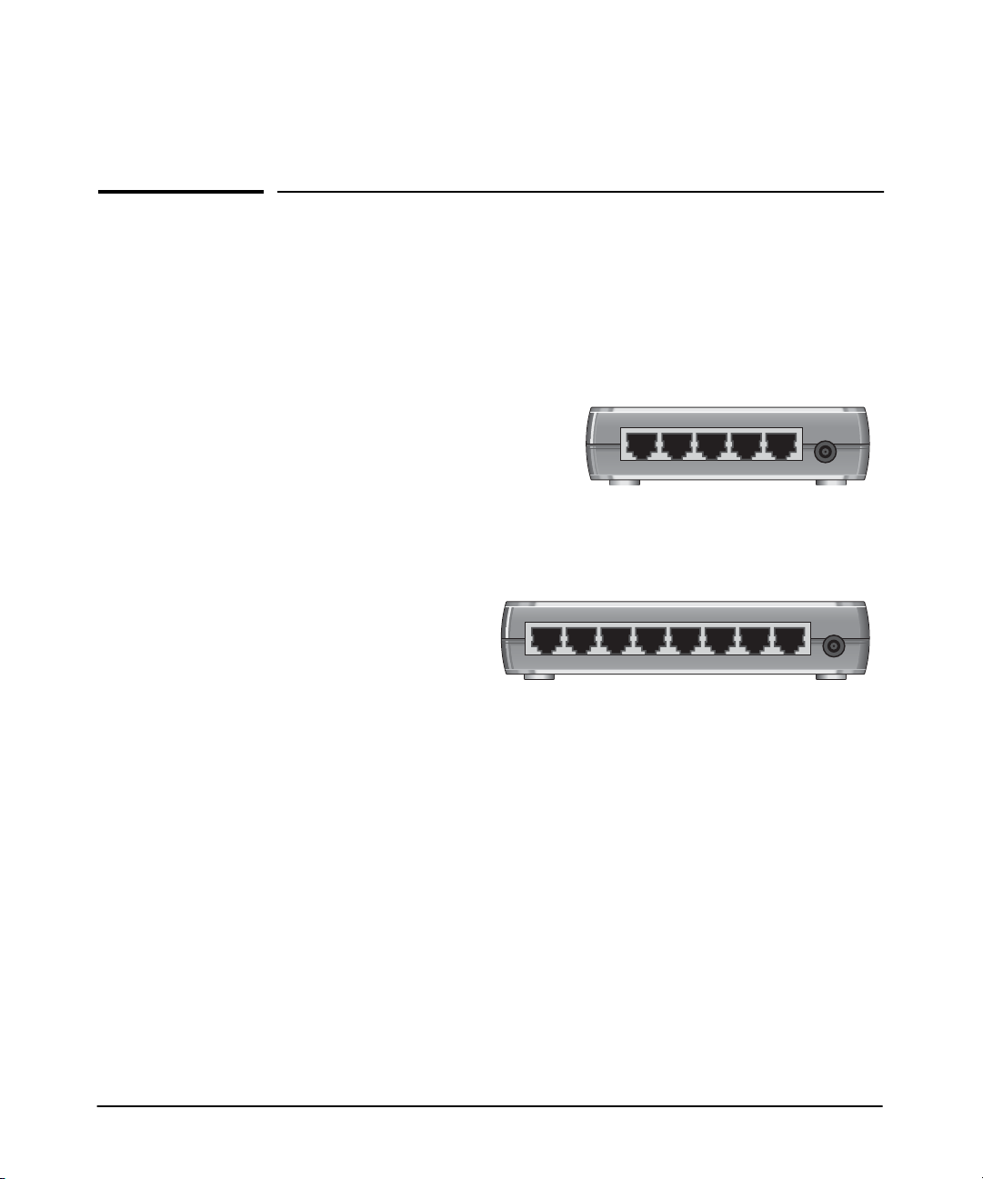
The HP 1405-5, 1405-5G, 1405-8, and 1405-8G Switches are multiport
unmanaged switches that can be used to build high-performance switched
workgroup networks. Theseswitches are store-and-forward devices that offer
low latency for high-speed networking.
1
HP 1405-5 Switch (J9791A)
HP 1405-5G Switch (J9792A)
54321
HP 1405-8 Switch (J9793A)
HP 1405-8G Switch (J9794A)
87654321
Throughout this manual, these switches will be referred to as the 1405-5
Switch, 1405-5G Switch, 1405-8 Switch, and 1405-8G Switch.
■ The 1405-5 Switch has 5 auto-sensing 10/100Base-TX RJ-45 ports.
■ The 1405-5G Switch has 5 auto-sensing 10/100/1000Base-T RJ-45 ports.
■ The 1405-8 Switch has 8 auto-sensing 10/100Base-TX RJ-45 ports.
■ The 1405-8G Switch has 8 auto-sensing 10/100/1000Base-T RJ-45 ports.
These switches can be directly connected to computers, printers, and servers
to provide dedicatedbandwidth to thosedevices, and youcan build aswitched
network infrastructure by connecting the switch to other switches or routers.
1-1
Page 8
Introducing the Switch
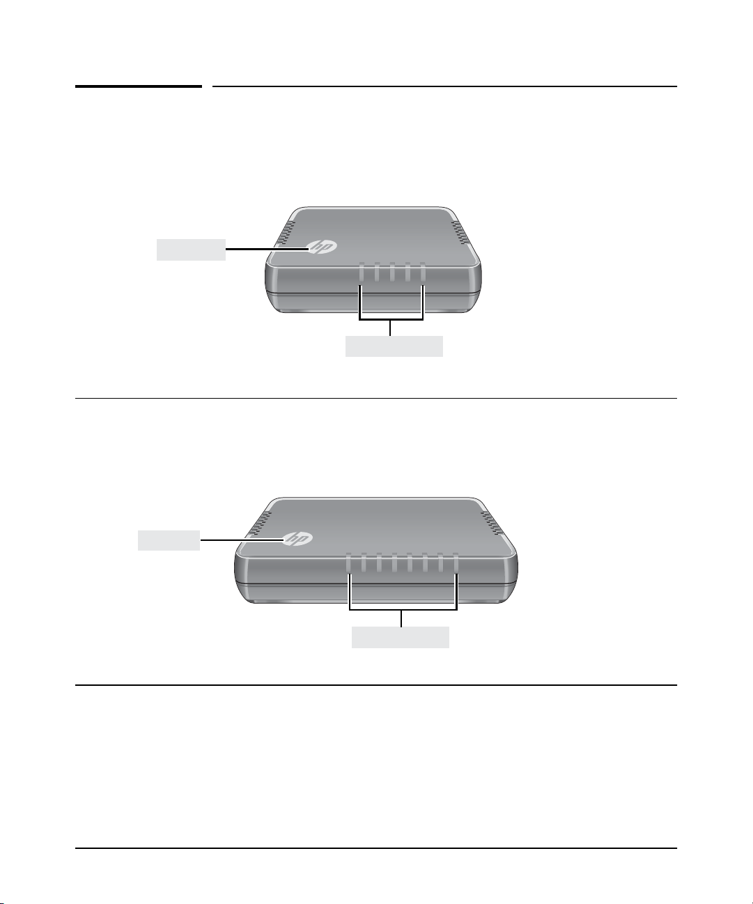
Front of the Switch
Front of the Switch
HP 1405-5 Switch (J9791A)
HP 1405-5G Switch (J9792A)
Power LED
Power LED
5
4
321
Link/Activity LEDs
4
321
Link/Activity LEDs
HP 1405-8 Switch (J9793A)
HP 1405-8G Switch (J9794A)
8765
1-2
Page 9

Network Ports
The network ports support “Auto-MDIX” feature, which means that you can
use either straight-through or crossover twisted-pair cables to connect any
network devices to the switch.
■ 5 or 8 auto-sensing 10/100Base-TX ports.
■ 5 or 8 auto-sensing 10/100/1000Base-T ports (for 1405-5G and 1405-8G
only).
LEDs
The front panels of the switches provide status LEDs for system monitoring.
Table 1-1 details the functions of the LED indicators.
Table 1-1. Switch Status LEDs
Switch LEDs State Meaning
Introducing the Switch
Front of the Switch
HP Power LED
(white)
Port LEDs
Link/Act
(blue)
1
The flashing behavior is an on/off cycle once every 0.083 seconds approximately.
On The switch is properly receiving power.
Off No power connection. The switch is NOT receiving power.
On The port is enabled and receiving a link indication from the connected device.
Off One of these condition exists:
• no active network cable is connected to the port
• the port is not receiving link beat or sufficient light
1
Flashing
Indicates that there is network activity on the port.
1-3
Page 10
Introducing the Switch
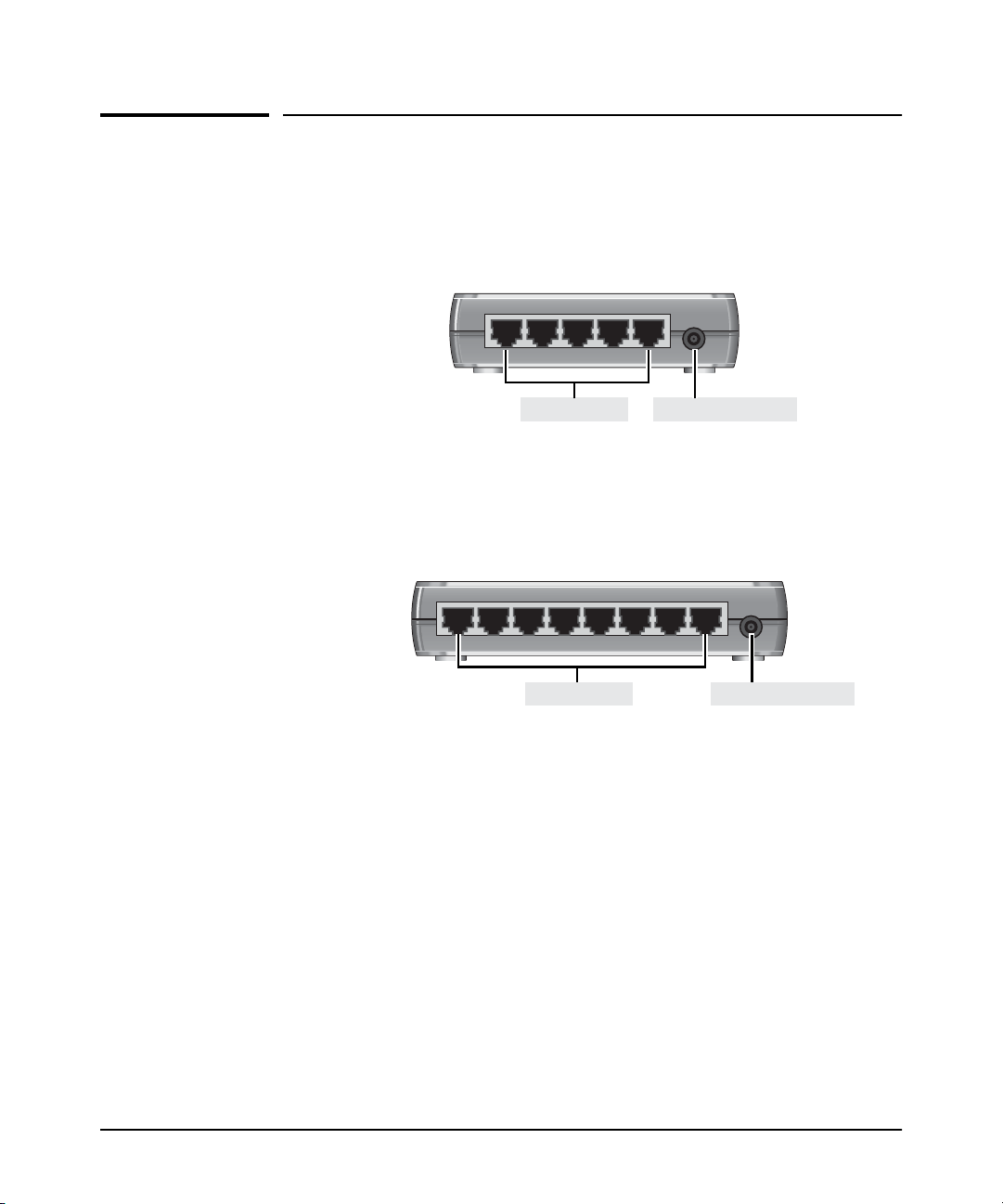
Back of the Switch
Back of the Switch
HP 1405-5 Switch (J9791A)
HP 1405-5G Switch (J9792A)
54321
RJ-45 ports DC power connector
HP 1405-8 Switch (J9793A)
HP 1405-8G Switch (J9794A)
87654321
RJ-45 ports DC power connector
Power Connector
The switches do not have a power switch. They are powered on when the
external AC/DC power adapter is connected to the switch and to a power
source. The external AC/DC power adapter supplies 12 volts DC to the switch
and automatically adjusts to any AC voltage between 100-240 volts and either
50 or 60 Hz. No voltage range settings are required.
1-4
Page 11

Introducing the Switch
Switch Features
Switch Features
The features of the switches include:
■ All 10/100Base-TX and 10/100/1000Base-T RJ-45 ports are auto-sensing
and support Auto-MDIX.
■ Plug-and-play networking—all ports are enabled—just connect the
network cables to active network devices and your switched network is
operational.
■ Automatically negotiated full-duplex operation for the RJ-45 ports when
connected to other auto-negotiating devices.
■ The 1405-5G and 1405-8G models comply with IEEE 802.3ab
(1000Base-T) standards.
■ The network ports support the IEEE 802.3az Energy Efficient Ethernet
standard, which reduces power consumption when connected with
EEE-compliant client devices.
■ Automatic learning of the hardware addresses in each switch’s address
forwarding table. Each switch has different MAC address table sizes:
• 1405-5 Switch and 1405-5G Switch: 2K
• 1405-8 Switch: 1K
• 1405-8G Switch: 8K
■ The 1405-5G Switch and 1405-8G Switch include support for up to
9216-byte Jumbo frames to improve performance of large data transfers.
■ The 1405-5 Switch includes support for up to 2048-byte mini-Jumbo
frames to improve performance of large data transfers.
■ Support for IEEE 802.1p prioritization Quality of Service (QoS) to deliver
data to devices based on the priority and type of traffic.
■ Support for EAPoL packet forwarding for 802.1x client authentication.
■ Support for BPDU packet forwarding for switch deployment in spanning
tree networks.
■ Support for Differentiated Services Code Point (DSCP).
■ Fanless designed enables quiet operation for deployment in open spaces.
1-5
Page 12

Installing the Switch
This chapter provides installation information for the 1405-5 Switch,
1405-5G Switch, 1405-8 Switch, and 1405-8G Switch.
Included Parts
The switches have the following components:
■ Documentation kit
■ Wall/table-mount accessory kit:
• Four rubber feet
• Two wall-mount tapping screws
• Two wall-mount anchors
2
2-1
Page 13

Installing the Switch
Included Parts
■ External AC/DC power adapters and power cords, one of the following:
• Universal External AC/DC Power Adapter
All countries/regions 5066-1122
Power cord options for Universal AC/DC Adapter
Australia/New Zealand
China
Continental Europe/Denmark/
....Switzerland/Israel/Vietnam/Indonesia
India
Japan
South Africa
Taiwan
Thailand
United Kingdom/United Arab Emirates (UAE)/
....Hong Kong/Singapore/Malaysia
United States/Canada/Mexico
Brazil
Argentina
Chile
• Wall Plug-in External AC/DC Power Adapter
(AC Power cords are not used)
United States/Canada
Continental Europe/Denmark/
....Norway/Sweden/Switzerland
8121-0870
8120-8373
8120-6314
8121-0702
8120-6316
8120-6317
8121-0963
8121-0664
8120-8699
8120-6313
8121-1081
8120-8367
8121-0514
5184-5863
5184-5864
Japan Power
Cord Warning
2-2
Page 14

Installing the Switch
Included Parts
Installation Precautions
WARNING ■ Wall-mount the switches with network ports facing up (away from
the floor) or down (toward the floor). Do not wall-mount any of
the switches with the ventilation ducts facing up or down.
Cautions ■ Use only the AC/DC power adapter supplied with the switch for
connection to an AC power source.
■ If your installation requires a different power cord than the one supplied
with the switch, ensure the cord is adequately sized for the switch’s
current requirements. In addition, be sure to use a power cord displaying
the mark of the safety agency that defines the regulations for power cords
in your country. The mark is your assurance that the power cord can be
used safely with the switch. If the supplied power cord does not fit,
contact HP networking support.
■ When installing the switch, the AC outlet should be near the switch and
should be easily accessible in case the switch must be powered off.
■ Ensure the switch does not overload the power circuits, wiring, and
over-current protection. To determine the possibility of overloading the
supply circuits, add together the ampere ratings of all devices installed on
the same circuit as the switch and compare the total with the rating limit
for the circuit. Maximum ampere ratings areusually printed on thedevices
near the AC power connectors.
■ Do not install the switch in an environment where the operating ambient
temperature might exceed 40°C (104°F). This includes a fully-enclosed
rack. Ensure the air flow around the sides and back of the switch is not
restricted. Leave at least 7.6 cm (3 inches) for cooling.
■ For indoor use only. For safe and reliable operation, do not install the
switch or LAN cables outdoors.
2-3
Page 15

Installing the Switch
Installation Procedures
Installation Procedures
These steps summarize your switch installation. The rest of this chapter
provides details on these steps.
1. Prepare the installation site (page 2-5). Make sure the physical
environment into which you will be installing the switch is properly
prepared, including having the correct network cabling ready to connect
to the switch and having an appropriate location for the switch. See page
2-3 for some installation precautions.
2. Verify the switch passes self test (page 2-6). Plug the switch into a
power source and observe that the LEDs on the switch’s front panel
indicate correct switch operation.
3. Mount the switch (page 2-8). The switches can be mounted on a wall
or on a horizontal surface.
4. Connect power to the switch (page 2-11). Once the switch is mounted,
plug it into the main power source.
5. Connect the network devices (page 2-12). Using the appropriate
network cables, connect the network devices to the switch ports.
At this point, your switch is fully installed. See the rest of this chapter if you
need more detailed information on any of these installation steps.
2-4
Page 16

Installing the Switch
Installation Procedures
1. Prepare the Installation Site
■ Cabling Infrastructure - Ensure the cabling infrastructure meets the
necessary network specifications. See appendix A, “Cabling and
Technology Information Specifications” for more information:
■ Installation Location- Before installing the switch, plan its location and
orientation relative to other devices and equipment:
• On the back of the switch, leave at least 7.6 cm (3 inches) of space for
the twisted-pair cabling.
• On the back of the switch, leave at least 3.8 cm (1 1/2 inches) of space
for the power cord.
• On the sides of the switch, leave at least 7.6 cm (3 inches) for cooling.
2-5
Page 17

Installing the Switch
Installation Procedures
2. Verify the Switch Passes Self Test
Before mounting the switch in its network location, you should first verify it
is working properly by plugging it into a power source and verifying it passes
its self test.
1. Connect the AC/DC adapter’s power cord to the power connector on the
back of the switch, and then plug the AC/DC power adapter into a nearby
properly grounded electrical outlet.
Note The switches are shipped with one of two types of AC/DC power adapter;
either the universal AC/DC adapter with an AC power cord, or the wall plugin AC/DC adapter (without an AC power cord).
8
Connect the wall plug-in
AC/DC power adapter to
the switch and an AC
power outlet
8
7
6
5
4
3
2
8
7
6
5
4
3
1
2
Connect the universal
AC/DC power adapter to
the switch and an AC
power outlet
Figure 2-1. Connecting the switch power adapter
2-6
Page 18

Installing the Switch
Installation Procedures
Note The switches do not have a power switch. They are powered on when the
external AC/DC power adapter is connected to the switch and the adapter
power cord to a power source. The external AC/DC power adapter
automatically adjusts to any voltage between 100-240 volts and either 50 or
60 Hz.
If your installation requires a different power cord than the one supplied with
the switch, be sure the cord is adequately sized for the switch’s current
requirements. In addition, be sure to use a power cord displaying the mark of
the safety agency that defines the regulations for power cords in your country.
The mark is your assurance that the power cord can be used safely with the
switch. If the supplied power cord does not fit, contact HP networking
support.
Caution Use only the AC/DC power adapter and power cord, supplied with the switch.
Use of other adapters or power cords, including those that came with other
HP networking products, may result in damage to the equipment.
2. Check the LEDs on the switch as described below.
2-7
Power LED
4
321
Link/Act LEDs
8765
Figure 2-2. Checking the LEDs
When the switch is powered on, the switch is initialized. Initialization takes
approximately one or two seconds, depending on the switch model.
Page 19

Installing the Switch
Installation Procedures
LED Behavior
After Initialization:
• The Power LED remains on.
• The port Link/Act LEDs on the front of the switch go into their normal
operational mode:
– If the ports are connected to active network devices, the Link/Act
LEDs stay on or may be blinking to indicate port activity.
– If the ports are not connected to active network devices, the
Link/Act LEDs will stay off.
If the LED display is different than what is described above, the self test
has not completed correctly. Refer to chapter 4, “Troubleshooting” for
diagnostic help.
3. Mount the Switch
After the switch passes self test, it is ready to be mounted in a stable location.
The switch can be mounted in these ways:
■ on a horizontal surface
■ on a wall
Wall Mounting
You can mount the switch on a wall.A special kit for wall mounting is included
with the switch.
Caution The switch should be mounted only to a wall or wood surface that is at least
1/2-inch (12.7 mm) plywood or its equivalent.
1. In the required location, mark the position for the mounting screws.
2. Use a Phillips #2 (cross-head) screwdriver and two of the included
∅ 3.5mm tapping screws to mount the switch on the wall or wood surface.
Screws and wall anchors are included in the accessory kit for use with
plastered brick or concrete walls.
2-8
Page 20

Installing the Switch
Installation Procedures
RJ-45 Ports
Wall
Wall anchors
Tapping screws
Figure 2-3. Wall mounting the switch
Horizontal Surface Mounting
Place the switch on a table or other horizontal surface. The switch comes with
rubber feet in the accessory kit that can be used to help keep the switch from
sliding on the surface.
Attach the rubber feet to the four corners on the bottom of the switch within
the embossed angled lines. Use a sturdy surface in an uncluttered area. You
may want to secure the networking cables and switch power cord to the table
leg or other part of the surface structure to help prevent tripping over the
cords.
Caution Ensure the air flow is not restricted around the switch.
2-9
Page 21

Figure 2-4. Horizontal surface mounting
Installing the Switch
Installation Procedures
2-10
Page 22

Installing the Switch
Installation Procedures
4. Connect the Switch to a Power Source
1. Plug the AC/DC adapter’s power cord into the switch, and then plug the
AC/DC power adapter into a nearby AC power source.
Note The switches are shipped with one of two types of AC/DC power adapter;
either the universal AC/DC adapter with an AC power cord, or the wall plugin AC/DC adapter (without an AC power cord).
8
Connect the wall plug-in
AC/DC power adapter to the
switch and an AC power outlet
2-11
8
7
6
5
4
3
2
8
7
6
5
4
3
1
2
Connect the universal AC/DC
power adapter to the switch and
an AC power outlet
Figure 2-5. Connecting power to the switch
2. Re-check the LEDs during self test. See “LED Behavior” on page 2-8.
Page 23

Installing the Switch
Installation Procedures
Caution Use only the AC/DC power adapter and power cord (if applicable), supplied
with the switch. Use of other adapters or power cords, including those that
came with other HP networking products, may result in damage to the
equipment.
5. Connect the Network Cables
Connect the network cables, described under “Cabling Infrastructure” (page
2-5), from the network devices or your patch panels to the fixed RJ-45 ports
on the switch.
Using the RJ-45 Connectors
To connect:
Push the RJ-45 plug into the RJ-45
port until the tab on the plug clicks
into place. When power is on for
the switch and for the connected
device, the Link/Act LED for the
port should light to confirm a
powered-on device (for example,
an end node) is at the other end of
the cable.
If the Link/Act LED does not go on
when the network cable is
connected to the port, see
“Diagnosing with the LEDs” in
chapter 4, “Troubleshooting”.
To disconnect:
Press the small tab on the plug and
pull the plug out of the port.
87654321
RJ-45 connector
Unshielded twisted-pair cable:
• Category 3, 4, or 5 for 10 Mbps ports
• Category 5 or better for 100 Mbps ports
• Category 5e or better for 1000 Mbps ports
Maximum distance: 100 meters
Figure 2-6. Connecting network cables
2-12
Page 24

Installing the Switch
Sample Network Topologies
Twisted-pair
straight-through
or cross-over
cables
87654321
Sample Network Topologies
This section shows a few sample network topologies for implementing the
switches.
INTERNET
Router Cable / ADSL Modem
Figure 2-7. Basic configuration
The switches are designed to be used as desktop switches to which end nodes,
printers and other peripherals are directly connected, as shown in the above
illustration.
Because the switches have the Auto-MDIX feature, the connections between
the switches and end nodes or servers can be through category 5
straight-through or cross-over twisted-pair cable. Category 3 or 4 cable can
also be used if the connection is 10 Mbps only.
2-13
Page 25

Troubleshooting
This chapter describes how to troubleshoot your 1405-5 Switch, 1405-5G
Switch, 1405-8 Switch, and 1405-8G Switch. This document describes
troubleshooting from a hardware perspective.
This chapter describes the following:
■ basic troubleshooting tips (page 3-1)
■ diagnosing with the LEDs (page 3-3)
■ hardware diagnostic tests (page 3-5)
■ HP Customer Support Services (page 3-6)
Basic Troubleshooting Tips
3
Most problems are caused by the following situations. Check for these items
first when starting your troubleshooting:
■ Connecting to devices that have a fixed full-duplex configuration.
The RJ-45 ports are configured as “Auto”. That is, when connecting to
attached devices, the switch operates in one of two ways to determine the
link speed and the communication mode (half duplex or full duplex):
• If the connected device is also configured to Auto, the switch will
automatically negotiate both link speed and communication mode.
• If the connected device has a fixed configuration, for example
100 Mbps,
the link speed, but will default to a communication mode of half
duplex.
at half or full duplex, the switch will automatically sense
Caution Because the switches behave in this way (in compliance with the IEEE
802.3 standard), if a device connected to the switch has a fixed
configuration at full duplex, the device will not connect correctly to the
switch. The result will be high error rates and very inefficient
communications between the switch and the device.
Ensure all devices connected to the switches are configured to auto
negotiate, or are configured to connect at half duplex (all hubs are
configured this way, for example).
3-1
Page 26

Troubleshooting
Basic Troubleshooting Tips
■ Faulty or loose cables. Look for loose or obviously faulty connections.
If the cables appear to be OK, make sure the connections are snug. If that
does not correct the problem, try a different cable.
■ Non-standard cables. Non-standard and miswired cables may cause
network collisions and other network problems, and can seriously impair
network performance. Use a new correctly-wired cable or compare your
cable to the cable in appendix A, “Cabling and Technology Information
Specifications”
for pinouts and correct cable wiring. A category 5 cable
tester is a recommended tool for every 100Base-TX and 1000Base-T
network installation.
■ Improper Network Topologies. It is important to make sure you have
a valid network topology. Common topology faults include excessive
cable length and excessiverepeater delays betweenend nodes. If youhave
network problems after recent changes to the network, change back to
the previous topology. If you no longer experience the problems, the new
topology is probably at fault.
In addition, you should make sure that your network topology contains
no data path loops. Between any two end nodes, there should be only
one active cabling path at any time. Data path loops will cause broadcast
storms that will severely impact your network performance.
3-2
Page 27

Diagnosing with the LEDs
Troubleshooting
Diagnosing with the LEDs
Table 3-1 shows LED patterns on the switch that indicate problem conditions
for general switch operation troubleshooting.
LED patterns for General Switch Troubleshooting
1. Check in the table for the LED pattern you see on your switch.
2. Refer to the corresponding diagnostic tip on the next few pages.
Table 3-1. LED Error Indicators
LED Pattern Indicating Problems
Power Port Link/Act LED
Off with power cord plugged in See Note 1
On Off with cable connected
1
This LED is not important for the diagnosis.
Diagnostic Tips
➊
➋
3-3
Page 28

Troubleshooting
Diagnosing with the LEDs
Diagnostic Tips:
Tip Problem Solution
➊
➋
The switch is not
plugged into an
active AC power
source, or the
switch’s power
supply may have
failed.
The network
connection is not
working
properly.
1. Verify the power cord is plugged into an active power source and to the switch. Make
sure these connections are snug.
2. Try power cycling the switch by unplugging and plugging the power cord back in.
3. If the Power LED is still not on, verify the AC power source works by plugging another
device into the outlet. Or try plugging the switch into a different outlet or try a different
power cord.
If the power source and power cord are OK and this condition persists, the switch power
supply may have failed. Call your HP networking authorized network reseller, or use the
electronic support services from HP to get assistance. For software license, warranty,
and support information, visit www.hp.com/networking/support.
Try the following procedures:
• For the indicated port, verify that both ends of the cabling, at the switch and the
connected device, are connected properly.
• Verify the connected device and switch are both powered on and operating correctly.
• Verify you have used the correct cable type for the connection:
– For twisted-pair connections to the fixed 10/100/1000 ports, either straight-through
or cross-over cables can be used because of the switch’s “Auto-MDIX” feature
and the Auto MDI/MDI-X feature of the 10/100/1000-T port.
• For 1000Base-T connections, verify the network cabling complies with the IEEE 802.3ab
standard. The cable should be installed according to the ANSI/TIA/EIA-568-A-5
specifications. Cable testing should comply with the stated limitations for Attenuation,
Near-End Crosstalk, Far-End Crosstalk, Equal-Level Far-End Crosstalk (ELFEXT),
Multiple Disturber ELFEXT, and Return Loss.
The cable verification process must include all patch cables from any end devices,
including the switch, to any patch panels in the cabling path.
• Verify the switch port configuration of the attached device. All switch ports are
configured as “Auto”, so ports on the attached device also MUST be configured as
“Auto”. Depending on the port type, twisted-pair or fiber-optic, if the configurations
do not match, the results could be a very unreliable connection, or no link at all.
• If the other procedures don’t resolve the problem, try using a different port or a different
cable.
3-4
Page 29

Hardware Diagnostic Tests
Troubleshooting
Hardware Diagnostic Tests
Testing the Switch by Resetting It
If you believe the switch is not operating correctly, you can reset the switch
to test its circuitry and operating code. To perform a reset, power cycle the
switch; unplug the power cord, wait 2 seconds, then reconnect power.
Power cycling the switch causes the switch to perform its power-on self test.
Testing Twisted-Pair Cabling
Network cables that fail to provide a link or provide anunreliable link between
the switch and the connected network device may not be compatible with the
IEEE 802.3 Type10Base-T, 100Base-TX, or 1000Base-Tstandards. The twistedpair cables attached to the switch must be compatible with the appropriate
standards. To verify your cable is compatible with these standards, use a
qualified cable test device.
Testing End-to-End Network Communications
Both the switch and the cabling can be tested by running an end-to-end
communications test—a test that sends known data from one network device
to another through the switch. For example, if you have two PCs on the
network that have LAN adapters between which you can run a link-level test
or Ping test through the switch, you can use this test to verify that the entire
communication path between the two PCs is functioning correctly. See your
LAN adapter documentation for more information on running a link test or
Ping test.
3-5
Page 30

Troubleshooting
HP Customer Support Services
HP Customer Support Services
If you are stillhaving trouble with yourswitch, Hewlett-Packard offers support
24 hours a day, seven days a week through the use of a number of automated
electronic services. The HP Web site, www.hp.com/networking/support also
provides up-to-date support information.
Additionally, your HP-authorized network reseller can provide you with
assistance, both with services that they offer and with services offered by HP.
Before Calling Support
Before calling your networking dealer or HP Support, to make the support
process most efficient, you first should retrieve the following information:
Information Item Information Location
• Product identification On the switch
• Copy of your network topology map, including
network addresses assigned to the relevant devices
Your network records
3-6
Page 31

Specifications
Switch Specifications
Physical
A
1405-5 Switch (J9791A)
1405-5G Switch (J9792A)
1405-8 Switch (J9793A)
1405-8G Switch (J9794A)
Width
11.5 cm (4.53 in) 9.15 cm (3.6 in) 3.35 cm (1.32 in) 0.18 kg (0.4lbs)
11.5 cm (4.53 in) 9.15 cm (3.6 in) 3.35 cm (1.32 in) 0.18 kg (0.4 lbs)
15.5 cm (6.10 in) 9.15 cm (3.6 in) 3.35 cm (1.32 in) 0.23 kg (0.5 lbs)
15.5 cm (6.10 in) 9.15 cm (3.6 in) 3.35 cm (1.32 in) 0.23 kg (0.5 lbs)
Electrical
15W Inline External Adapter
(P/N: 5066-1122)
13W Wall-Plug External Adapter
(P/Ns: 5184-5863 and 5184-5864)
1405-5 Switch (J9791A)
Depth Height Weight
AC Voltage AC Input
100-240 volts 50-60 Hz 1.25A
100-240 volts 50-60 Hz 1.085A
DC Voltage DC Maximum Current
12 volts 0.15A
Maximum Output
Current
1405-5G Switch (J9792A)
1405-8 Switch (J9793A)
1405-8G Switch (J9794A)
12 volts 0.17A
12 volts 0.16A
12 volts 0.33A
A-1
Page 32

Specifications
Switch Specifications
Environmental
Operating Non-Operating
Temperature 0°C to 40°C (32°F to 104°F) -40°C to 70°C (-40°F to 158°F)
Relative humidity
(non-condensing)
Maximum altitude 3048 m (10,000 ft)* 3048 m (10,000 ft)
15% to 95% at 40°C (104°F) 15% to 90% at 65°C (149°F)
* The operating maximum altitude should not exceed that of any accessory being connected
to any switch.
Acoustics
No fans.
Safety
■ EN 60950-1:2006 ; IEC 60950-1:2005
■ CSA-C22.2 No. 60950/UL 60950-2
A-2
Page 33

Cabling and Technology Information Specifications
Table A-1. Cabling Specifications
Cabling and Technology Information Specifications
Specifications
Twisted-pair copper
10 Mbps Operation Category 3, 4 or 5, 100-ohm unshielded twisted-pair (UTP) or
shielded twisted-pair (STP) cable, complying with IEEE 802.3
10BASE-T specifications.
100 Mbps Operation Category 5, 100-ohm UTP or STP cable, complying with IEEE 802.3u
100BASE-TX specifications.
1000 Mbps Operation Category 5, 100-ohm 4-pair UTP or STP cable, complying with IEEE
802.3ab 1000BASE-T specifications—Category 5e or better is
recommended. See note on 1000BASE-T Cable Requirements
below.
Note on 1000BASE-T Cable Requirements. The Category 5 networking
cables that work for 100BASE-TX connections should also work for
1000BASE-T, as long as all four-pairs are connected. But, for the most robust
connections, you should use cabling that complies with the Category 5e
specifications, as described in Addendum 5 to the TIA-568-A standard (ANSI/
TIA/EIA-568-A-5).
Because of theincreased speed providedby 1000BASE-T (Gigabit-T),network
cable quality is more important than for either 10BASE-T or 100BASE-TX.
Cabling plants being used to carry 1000BASE-T networking must comply with
the IEEE 802.3ab standards. In particular, the cabling must pass tests for
Attenuation, Near-End Crosstalk (NEXT), and Far-End Crosstalk (FEXT).
Additionally, unlike the cables for 100BASE-TX, the 1000BASE-T cables must
pass tests for Equal-Level Far-End Crosstalk (ELFEXT) and Return Loss.
When testing your cabling, be sure to include the patch cables that connect
the switch and other end devices to the patch panels on your site. The patch
cables are frequently overlooked when testing cable and they must also
comply with the cabling standards.
A-3
Page 34

Specifications
Twisted-Pair Cable/Connector Pin-Outs
Twisted-Pair Cable/Connector Pin-Outs
The Auto-MDIX Feature: In the default configuration, “Auto”, the fixed 10/
100/1000Base-T ports on the switches all automatically detect the type of port
on the connected device and operate as either an MDI or MDI-X port,
whichever is appropriate. So for any connection, a straight-through twistedpair cable can be used—you no longer have to use crossover cables, although
crossover cables can also be used for any of the connections. (The 10/100/
1000-T ports support the IEEE 802.3ab standard, which includes the “AutoMDIX” feature.)
If you connect a switch twisted-pair port to another switch or hub, which
typically have MDI-X ports, the switch port automatically operates as an MDI
port. If you connect it to an end node, such as a server or PC, which typically
have MDI ports, the switch port operates as an MDI-X port. In all cases, you
can use standard straight-through cables or crossover cables.
If you happen to use a correctly wired crossover cable, though, the switch will
still be able to automatically detect the MDI/MDI-X operation and link
correctly to the connected device.
Note Using Fixed Configurations. If the port configuration is changed to any of
the fixed configurations though, for example 100 Mbps/full duplex, the port
operates as MDI-X only and the correct cable type must be used: for
connections to MDI ports, such as end nodes, use a straight-through cable; for
connections to MDI-X ports, such as on hubs and other switches, use a
crossover cable.
Other Wiring Rules:
■ All twisted-pair wires used for 10 Mbps, and 100 Mbps operation must be
twisted through the entire length of the cable. The wiring sequence must
conform to EIA/TIA 568-B (not USOC). See “Twisted-Pair Cable Pin
Assignments” later in this appendix for a listingof the signals used oneach
pin.
■ For 1000Base-T connections, all four pairs of wires in the cable must be
available for data transmission.
■ For 10 Mbps connections to the ports, you can use Category 3, 4, or 5
unshielded twisted-pair cable, as supported by the IEEE 802.3 Type
10Base-T standard.
A-4
Page 35

Twisted-Pair Cable/Connector Pin-Outs
■ For 100 Mbps connections to the ports, use 100-ohm Category 5 UTP or
Specifications
STP cable only, as supported by the IEEE 802.3u Type 100Base-TX
standard.
■ For 1000 Mbps connections, 100-ohm Category 5e or better cabling is
recommended.
A-5
Page 36

Specifications
Twisted-Pair Cable/Connector Pin-Outs
Straight-through Twisted-Pair Cable for 10 Mbps or 100 Mbps Network Connections
Because of the Auto-MDIX operation of the 10/100 ports on the switch, for all
network connections, to PCs, servers or other end nodes, or to hubs or other
switches, you can use straight-through cables.
If any of these ports are given a fixed configuration, for example 100 Mbps/
Full Duplex, the ports operate as MDI-X ports, and straight-through cables
must be then used for connections to PC NICs and other MDI ports.
Cable Diagram
Note Pins 1 and 2 on connector “A” must be wired as a twisted pair to pins 1 and 2
on connector “B”.
Pins 3 and 6 on connector “A” must be wired as a twisted pair to pins 3 and 6
on connector “B”.
Pins 4, 5, 7, and 8 are not used in this application, although they may be wired
in the cable.
.
Pin Assignments
A-6
Switch End (MDI-X) Computer, Transceiver, or
Signal Pins Pins Signal
receive +
receive transmit +
transmit -
1
2
3
6
Other End
1
2
3
6
transmit +
transmit receive +
receive -
Page 37

Twisted-Pair Cable/Connector Pin-Outs
Specifications
Crossover Twisted-Pair Cable for 10 Mbps or 100 Mbps Network Connection
The Auto-MDIX operation of the 10/100 ports on the switch also allows you to
use crossover cables for all network connections, to PCs, servers or other end
nodes, or to hubs or other switches.
If any of these ports are given a fixed configuration, for example 100 Mbps/
Full Duplex, the ports operate as MDI-X ports, and crossover cables must be
then used for connections to hubs or switches or other MDI-X network
devices.
Cable Diagram
Note Pins 1 and 2 on connector “A” must be wired as a twisted pair to pins 3 and 6
on connector “B”.
Pins 3 and 6 on connector “A” must be wired as a twisted pair to pins 1 and 2
on connector “B”.
Pins 4, 5, 7, and 8 are not used in this application, although they may be wired
in the cable.
Pin Assignments
Switch End (MDI-X) Hub or Switch Port, or Other
Signal Pins Pins Signal
receive +
receive transmit +
transmit -
1
2
3
6
MDI-X Port End
6
3
2
1
transmit transmit +
receive receive +
A-7
Page 38

Specifications
Twisted-Pair Cable/Connector Pin-Outs
Straight-Through Twisted-Pair Cable for 1000 Mbps Network Connections
1000Base-T connections require that all four pairs of wires be connected.
Cable Diagram
Note Pins 1 and 2 on connector “A” must be wired as a twisted pair to pins 1 and 2
on connector “B”.
Pins 3 and 6 on connector “A” must be wired as a twisted pair to pins 3 and 6
on connector “B”.
Pins 4 and 5 on connector “A” must be wired as a twisted pair to pins 4 and 5
on connector “B”.
Pins 7 and 8 on connector “A” must be wired as a twisted pair to pins 7 and 8
on connector “B”.
.
Pin Assignments
For 1000Base-T operation, all four pairs of wires are used for both transmit
and receive.
A-8
Page 39

EMC Regulatory Statements
Regulatory Statements
FCC Class B
This equipment has been tested and foundto comply with the limits for a Class
B digital device, pursuant to Part 15 of the FCC Rules. These limits are
designed to provide reasonable protection against harmful interference in a
residential installation. This equipment generates, uses and can radiate radio
frequency energy and, if not installed and used in accordance with the
instructions, may cause harmful interference to radio communications.
However, there is no guarantee that the interference will not occur in a
particular installation. If this equipment does cause harmful intereference to
radio or television reception, which can be determined by turning the
equipment off and on, the user is encouraged to try to correct the interference
by one or more of the following measures:
■ Reorient or relocate the receiving antenna.
■ Increase the separation between the equipment and receiver.
■ Connect the equipment into an outlet on a circuit different from that of
the receiver.
■ Consult the dealer or an experienced radio/TV technician for help.
B
B-1
Page 40

Index
Numerics
10/100Base-TX ports
location on switch … 1-2
A
AC power connector
location on back of switch … 1-4
acoustic specifications … A-2
auto MDI/MDI-X operation … A-6, A-8
HP Auto-MDIX feature … A-4
B
back of switch
description … 1-4
power connector … 1-4
basic troubleshooting tips … 3-1
C
cables
connecting cables to switch ports … 2-12
effects of non-standard cables … 3-2
infrastructure requirements … 2-5
cables, twisted pair
category 3, 4,5…A-4
cross-over cable pin-out … A-7
MDI-X to MDI connections … A-6, A-8
MDI-X to MDI-X connections … A-7
pin-outs … A-6, A-8
straight-through cable pin-out … A-6, A-8
switch-to-computer connection … A-6, A-8
switch-to-switch or hub connection … A-7
cables, twisted-pair
HP Auto-MDIX feature … A-4
wiring rules … A-4
cables, twisted-pair connector pin-outs … A-4
cabling infrastructure … 2-5
Clear button
location on switch … 1-2
connecting the switch to a power source … 2-11
console port
location on switch … 1-2
cross-over cable
pin-out … A-7
D
description
back of switch … 1-4
front of switch … 1-2
LEDs … 1-3
switch … 1-1
diagnostic tests … 3-5
end-to-end connectivity … 3-5
testing the switch only … 3-5
testing twisted-pair cabling … 3-5
E
electrical specifications, switch … A-1
environmental specifications, switch … A-2
F
Fault LED
behavior during self test … 2-8
location on switch … 1-2
features
switch … 1-5
flashing LEDs
error indications … 3-3
front of switch … 1-2
10/100/1000Base-T ports … 1-2
10/100Base-TX ports … 1-2
description … 1-2
LEDs … 1-3
network ports … 1-3
full-duplex fixed configuration
effects on network connections … 3-1
H
horizontal surface
mounting switch on … 2-9
HP Auto-MDIX
feature description … A-4
Index – 1
Page 41

I
included parts … 2-1
installation
connecting the switch to a power source … 2-11
horizontal surface mounting … 2-9
location considerations … 2-5
network cable requirements … 2-5
precautions … 2-3
site preparation … 2-5
wall mounting … 2-8
L
LEDs
behavior during self test … 2-8
descriptions of … 1-3
error indications … 3-3
Fault
behavior during self test … 2-8
location on switch … 1-2
on switch … 1-3
Power … 1-3
behavior during self test … 2-8
location for the switch, considerations … 2-5
M
MDI-X to MDI network cable … A-6, A-8
MDI-X to MDI-X network cable … A-7
mini-GBICs
slot, location on switch … 1-2
mounting the switch
in a rack or cabinet
precautions … 2-3
on a horizontal surface … 2-9
on a wall … 2-8
precautions … 2-8
N
network cables
HP Auto-MDIX feature … A-4
required types … 2-5
twisted-pair connector pin-outs … A-4
twisted-pair, wiring rules … A-4
network devices
connecting to the switch … 2-12
network ports
connecting to … 2-12
location on switch … 1-3
types of … 1-3
non-standard network cables, effects … 3-2
P
parts, included with the switch … 2-1
physical specifications, switch … A-1
pin-outs
twisted-pair cables … A-4
port LEDs
normal operation … 2-8
ports
10/100Base-TX, location on switch … 1-4
connecting to … 2-12
HP Auto-MDIX feature … A-4
network connections … 2-12
power connector … 1-4
Power LED … 1-3
behavior during self test … 2-8
behaviors … 1-3
location on switch … 1-2
power source
connecting the switch to … 2-11
precautions
mounting the switch … 2-3
power requirements … 2-3
preparing the installation site … 2-5
R
rack
mounting precautions … 2-3
Reset button
location on switch … 1-2
resetting the switch
troubleshooting procedure … 3-5
S
safety and regulatory statements … B-1
safety specifications … A-2
self test
Fault LED behavior … 2-8
LED behavior during … 2-8
Power LED behavior … 2-8
2 – Index
Page 42

slots for mini-GBICs
location on switch … 1-2
specifications
acoustic … A-2
electrical … A-1
environmental … A-2
physical … A-1
safety … A-2
straight-through cable
pin-out … A-6, A-8
switch
connecting to a power source … 2-11
description … 1-1
electrical specifications … A-1
environmental specifications … A-2
features … 1-5
front panel description … 1-2
included parts … 2-1
LED descriptions … 1-3
mounting on a wall … 2-8
mounting on horizontal surface … 2-9
physical specifications … A-1
switch operation
verifying after installation … 2-6
T
testing
diagnostic tests … 3-5
end-to-end communications … 3-5
switch operation … 3-5
twisted-pair cabling … 3-5
tips for troubleshooting … 3-1
topologies
effects of improper topology … 3-2
samples of … 2-13
troubleshooting … 3-1
basic tips … 3-1
common network problems … 3-1
connecting to fixed full-duplex devices … 3-1
diagnostic tests … 3-5
effects of improper topology … 3-2
effects of non-standard cables … 3-2
testing end-to-end communications … 3-5
testing the switch … 3-5
testing the twisted-pair cables … 3-5
twisted-pair cable
cross-over cable pin-out … A-7
pin-outs … A-4, A-6, A-8
straight-through cable pin-out … A-6, A-8
switch-to-computer connection … A-6, A-8
switch-to-switch or hub connection … A-7
testing … 3-5
twisted-pair ports
HP Auto-MDIX feature … A-4
W
wall
mounting switch on … 2-8
wiring rules for twisted-pair cables … A-4
Index – 3
Page 43

4 – Index
Page 44

5400zl Switches
Technology for better business outcomes
To learn more, visit www.hp.com/networking
© Copyright 2012 Hewlett-Packard Development Company, L.P.
The information contained herein is subject to change without notice. The only
warranties for HP products and services are set forth in the express warranty
statements accompanying such products and services. Nothing herein should
be construed as constituting an additional warranty. HP will not be liable for
technical or editorial errors or omissions contained herein.
May 2012
Manual Part Number
5998-3081
 Loading...