

Page 1

Page 2

3Com Corporation
350 Campus Drive
Marlborough, MA 01752-3064
Copyright © 2003, 3Com Corporation. All rights reserved. No part of this documentation
may be reproduced in any form or by any means or used to make any derivative work (such
as translation, transformation, or adaptation) without written permission from 3Com
Corporation.
3Com Corporation reserves the right to revise this documentation and to make changes in
content from time to time without obligation on the part of 3Com Corporation to provide
notification of such revision or change.
3Com Corporation provides this documentation without warranty, term, or condition of any
kind, either implied or expressed, including, but not limited to, the implied warranties, terms
or conditions of merchantability, satisfactory quality, and fitness for a particular purpose.
3Com may make improvements or changes in the product(s) and/or the program(s) described
in this documentation at any time.
If there is any software on removable media described in this documentation, it is furnished
under a license agreement included with the product as a separate document, in the hard
copy documentation, or on the removable media in a directory file named LICENSE.TXT or
!LICENSE.TXT. If you are unable to locate a copy, please contact 3Com and a copy will be
provided to you.
UNITED STATES GOVERNMENT LEGEND
If you are a United States government agency, then this documentation and the software
described herein are provided to you subject to the following:
All technical data and computer software are commercial in nature and developed solely at
private expense. Software is delivered as “Commercial Computer Software” as defined in
DFARS 252.227-7014 (June 1995) or as a “commercial item” as defined in FAR 2.101(a) and
as such is provided with only such rights as are provided in 3Com’s standard commercial
license for the Software. Technical data is provided with limited rights only as provided in
DFAR 252.227-7015 (Nov 1995) or FAR 52.227-14 (June 1987), whichever is applicable. You
agree not to remove or deface any portion of any legend provided on any licensed program
or documentation contained in, or delivered to you in conjunction with, this User Guide.
Unless otherwise indicated, 3Com registered trademarks are registered in the United States and
may or may not be registered in other countries.
3Com, the 3Com logo and OfficeConnect are registered trademarks of 3Com Corporation.
Intel and Pentium are registered trademarks of Intel Corporation. Microsoft, MS-DOS,
Windows, and Windows NT are registered trademarks of Microsoft Corporation. Novell and
NetWare are registered trademarks of Novell, Inc. UNIX is a registered trademark in the
United States and other countries, licensed exclusively through X/Open Company, Ltd.
Netscape Navigator is a registered trademark of Netscape Communications.
JavaScript is a trademark of Sun Microsystems
All other company and product names may be trademarks of the respective companies with
which they are associated.
ENVIRONMENTAL STATEMENT
It is the policy of 3Com Corporation to be environmentally-friendly in all operations. To
uphold our policy, we are committed to:
Establishing environmental performance standards that comply with national legislation and
regulations.
Conserving energy, materials and natural resources in all operations.
Reducing the waste generated by all operations. Ensuring that all waste conforms to
recognized environmental standards. Maximizing the recyclable and reusable content of all
products.
Ensuring that all products can be recycled, reused and disposed of safely.
Ensuring that all products are labelled according to recognized environmental standards.
Improving our environmental record on a continual basis.
End of Life Statement
3Com processes allow for the recovery, reclamation and safe disposal of all end-of-life
electronic components.
Regulated Materials Statement
3Com products do not contain any hazardous or ozone-depleting material.
Environmental Statement about the Documentation
The documentation for this product is printed on paper that comes from sustainable,
managed forests; it is fully biodegradable and recyclable, and is completely chlorine-free. The
varnish is environmentally-friendly, and the inks are vegetable-based with a low heavy-metal
content.
Page 3

CONTENTS
Contents 3
About This Guide 7
Naming Convention 7
Conventions 7
Introducing the OfficeConnect Secure Router 9
OfficeConnect Secure Router 9
Secure Router Advantages 10
Package Contents 11
Minimum System and Component Requirements 11
Front Panel 12
Rear Panel 13
Installing the Router 15
Introduction 15
Positioning the Router 15
Safety Information 15
Using the Rubber Feet 15
Using the Stacking Clip 15
Before you Install your Router 16
Dynamic IP Address (DSL or Cable) 16
PPPoE (DSL only) 16
Static IP Address (DSL or Cable) 16
PPTP (DSL or Cable) 16
Powering Up the Router 17
Connecting the Secure Router 17
Setting Up Your Computers 19
Obtaining an IP Address Automatically 19
Windows 2000, XP, 2003 Server 19
Windows 95, 98 20
Macintosh OS 8.5, 9.x 20
Disabling PPPoE and PPTP Client Software 20
Disabling Web Proxy 21
Running the Setup Wizard 23
Accessing the Wizard 23
Setting the Password 24
Setting the Time Zone 25
Auto-Configuration Settings 26
Internet Settings 26
Choosing your LAN Settings 30
Activating DHCP 30
Viewing the Summary 31
Router Configuration 33
Navigating Through the Router Configuration Pages 33
Main Menu 33
Option Tabs 33
Welcome Screen 34
Viewing the Notice Board 34
Changing the Administration Password 35
Setup Wizard 35
3
Page 4

Network Settings 35
Connection to ISP 36
LAN Settings 41
DHCP Clients List 42
Advanced Networking 44
Setting up NAT 44
Static Routing 46
Dynamic Routing 47
Dynamic DNS 48
Configuring the Router 48
The Virtual Servers Menu 48
PC Privileges 50
Special Applications 52
Advanced 55
Content Filtering 56
Allow/Block Lists 56
Filter Policy 57
Configuring VPNs 58
Setting the VPN Mode 58
Viewing VPN Connections 60
Editing IPSec Routes 66
Accessing the System Tools 67
Restart 67
Time Zone 68
Diagnostics Tools 68
Loading and Saving the Router Configuration 69
Upgrading the Firmware of your Router 69
Viewing Status and Logs 70
Obtaining Support and Feedback for your Router 72
Troubleshooting 75
Basic Connection Checks 75
Browsing to the Router Configuration Screens 75
Connecting to the Internet 76
Forgotten Password 76
Alert LED 77
Recovering from Corrupted Software 77
Frequently Asked Questions 78
Using Discovery 79
Running the Discovery Application 79
Windows Installation (95/98/XP/2000/2003 Server/NT) 79
IP Addressing 81
The Internet Protocol Suite 81
IP Addresses and Subnet Masks 81
4
Page 5

How does a Device Obtain an IP Address and Subnet Mask? 82
DHCP Addressing 82
Static Addressing 82
Auto-IP Addressing 83
Private IP Addresses 83
Technical Specifications 85
Interfaces 85
Operating Temperature 85
Power 85
Humidity 85
Dimensions 85
Weight 85
VPN Tunnels 85
Standards 85
System Requirements 86
Operating Systems 86
Ethernet Performance 86
Cable Specifications 86
Safety Information 87
Important Safety Information 87
Wichtige Sicherheitshinweise 87
Consignes importantes de sécurité 88
Troubleshoot Online 91
Access Software Downloads 91
Contact Us 92
Telephone Technical Support and Repair 92
End User Software Licence Agreement 95
3Com Corporation
END USER SOFTWARE LICENSE AGREEMENT 95
ISP Information 97
Information Regarding Popular ISPs 97
Glossary 99
Index 105
Regulatory Notices 111
Obtaining Support for your Product 91
Register Your Product to Gain Service Benefits 91
Purchase Value-Added Services 91
5
Page 6

6
Page 7
ABOUT THIS GUIDE
This guide is intended for use by those responsible for installing
and setting up network equipment; consequently, it assumes a
basic working knowledge of LANs (Local Area Networks) and
Internet security systems.
If a release note is shipped with this OfficeConnect Secure Router
and contains information that differs from the information in this
guide, follow the information in the release note.
Most user guides and release notes are available in Adobe Acrobat Reader Portable Document Format (PDF) on the 3Com World
Wide Web site:
http://www.3com.com
Naming Convention
Throughout this guide, the OfficeConnect Secure Router is
referred to as the Router.
Category 3 and Category 5 Twisted Pair Cables are referred to as
Twisted Pair Cables throughout this guide.
Conventions
Ta bl e 1 and Tab l e 2 list conventions that are used throughout this
guide.
Tabl e 1 Notice Icons
Icon Notice Type Description
Information note Information that describes important
Caution Information that alerts you to potential
Warning Information that alerts you to potential
Tabl e 2 Text Conventions
Convention Description
The words “enter”
and “type”
Keyboard key
names
When you see the word “enter” in this guide, you
must type something, and then press Return or Enter.
Do not press Return or Enter when an instruction
simply says “type.”
If you must press two or more keys simultaneously,
the key names are linked with a plus sign (+).
Example:
Press Ctrl+Alt+Del
features or instructions
loss of data or potential damage to an
application, system, or device
personal injury
7
Page 8
Tabl e 2 Text Conventions (continued)
Convention Description
Words in italics Italics are used to:
■ Emphasize a point.
■ Denote a new term at the place where it is defined
in the text.
■ Identify menu names, menu commands, and soft-
ware button names. Examples:
From the Help menu, select Contents.
Click OK.
Feedback about this User Guide
Your suggestions are very important to us. They will help make
our documentation more useful to you. Please e-mail comments
about this document to 3Com at:
pddtechpubs_comments@3com.com
Please include the following information when commenting:
■ Document title
■ Document part number (on the title page)
■ Page number (if appropriate)
Example:
■ OfficeConnect Secure Router User Guide
■ Part Number DUA08609-5AAA0x
■ Page 24
Do not use this e-mail address for technical support questions.
For information about contacting Technical Support, please refer
to “
Obtaining Support for your Product” on page 91.
8
Page 9
INTRODUCING THE OFFICECONNECT SECURE ROUTER
Welcome to the world of networking with 3Com®. In the
modern business environment, communication and sharing
information is crucial. Computer networks have proved to be one
of the fastest modes of communication but, until recently, only
large businesses could afford the networking advantage. The
OfficeConnect
bringing networks to the small office.
The products that compose the OfficeConnect line give you, the
small office user, the same power, flexibility, and protection that
has been available only to large corporations. Now, you can
network the computers in your office, connect them all to a
single Internet outlet, and harness the combined power of all of
your computers.
®
product range from 3Com has changed all this,
OfficeConnect Secure Router
The OfficeConnect Secure Router is designed to provide a
cost-effective means of sharing a single broadband Internet
connection amongst several computers.
The Router also increases your network security by acting as a
firewall, preventing unauthorised external access to your
network, and by creating Virtual Private Networks (VPNs) —
encrypted links to other private networks.
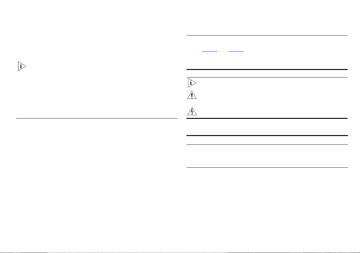
The example in Figure 1
Internet without a Router. One computer is connected to the
Internet using a Cable or DSL modem. This computer must
always be powered on for the other computers on the network
to access the Internet.
shows a network connected to the
Figure 1 Example Network Without a Secure Router
Cable/DSL
Modem
OfficeConnect
Switch
Internet
9
Page 10
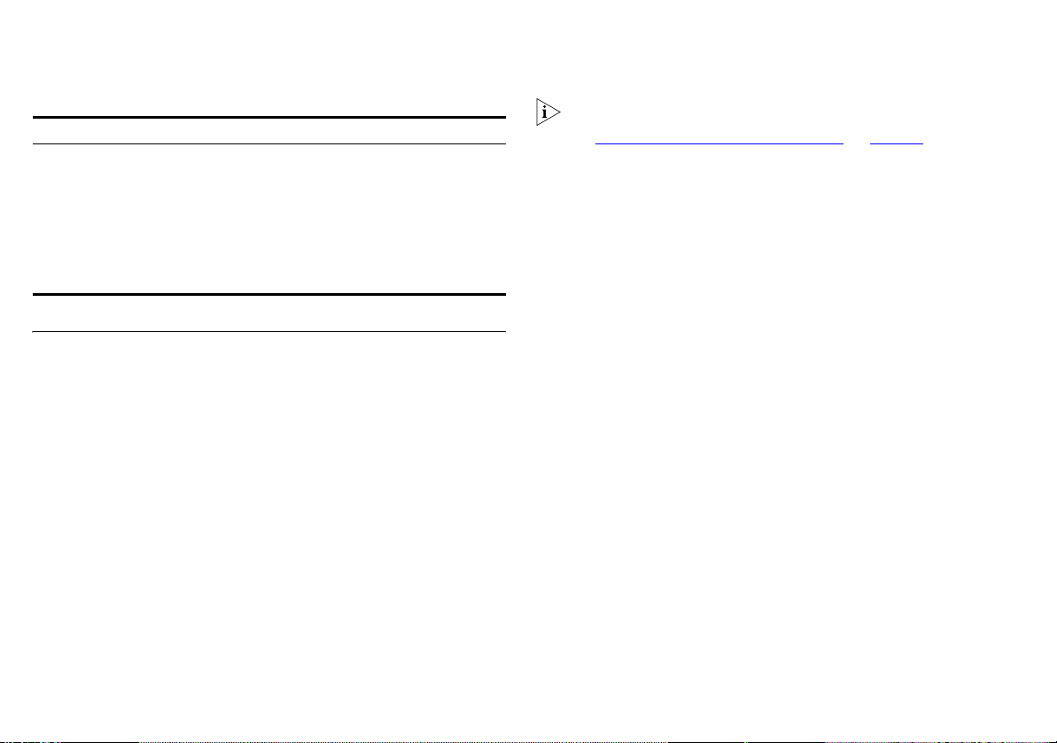
When you use the Secure Router in your network (Figure 2), it
becomes your connection to the Internet. Connections can be
made directly to the Router, or through an OfficeConnect Hub or
Switch, expanding the number of computers you can have in
your network.
Figure 2 Example Network Using a Secure Router
Your existing
Cable/DSL
Modem
OfficeConnect
Secure Router
Internet
OfficeConnect
VPN Firewall
Secure Router Advantages
The advantages of using the Secure Router include:
■ Provides firewall protection against Internet hacker attacks.
■ Implements Stateful Packet Inspection (SPI) to block net-
work intrusions.
■ Blocks Denial of Service (DoS) attacks by using pattern
detection.
■ Supports Virtual Private Networks (VPNs).
■ Initiates and terminates IPSec connections.
■ Terminates PPTP and L2TP over IPSec connections.
■ Provides hardware accelerated encryption for IPSec VPNs,
including L2TP over IPSec.
■ Shared Internet connection.
■ No need for a dedicated, “always on” computer serving as
your Internet connection.
■ Cross-platform operation for compatibility with Windows,
Unix and Macintosh computers.
■ Easy-to-use, Web-based setup and configuration.
■ Provides centralization of all network address settings (DHCP).
■ Provides Virtual Server redirection to enable remote access to
Web, FTP, and other services on your network
OfficeConnect
Switch
10
Page 11

Package Contents
The OfficeConnect Secure Router kit includes the following items:
■ One OfficeConnect Secure Router
■ One power adapter for use with the Router
■ Four rubber feet
■ One stacking clip
■ One Ethernet cable
■ One CD-ROM containing
■ the Discovery program
■ this User Guide
■ the license agreement
■ One Installation Guide
■ One Support and Safety Information sheet
■ One Warranty flyer
■ One License Agreement
If any of these items are missing or damaged, please contact
your retailer.
Minimum System and Component Requirements
Your OfficeConnect Secure Router requires that the computer(s)
and components in your network be configured with at least the
following:
■ A computer with an operating system that supports TCP/IP
networking protocols (for example Windows
95/98/NT/Me/2000/XP, Unix, Mac OS 8.5 or higher).
■ An Ethernet 10 Mbps or 10/100 Mbps NIC for each computer
to be connected to the four-port switch on your Router.
■ An Internet access device with an Ethernet (RJ-45) port, for
example a cable modem or DSL modem.
■ An active Internet access account.
■ A Web browser program that supports JavaScript, such as
Netscape 4.7 or higher or Internet Explorer 5.5 or higher.
11
Page 12
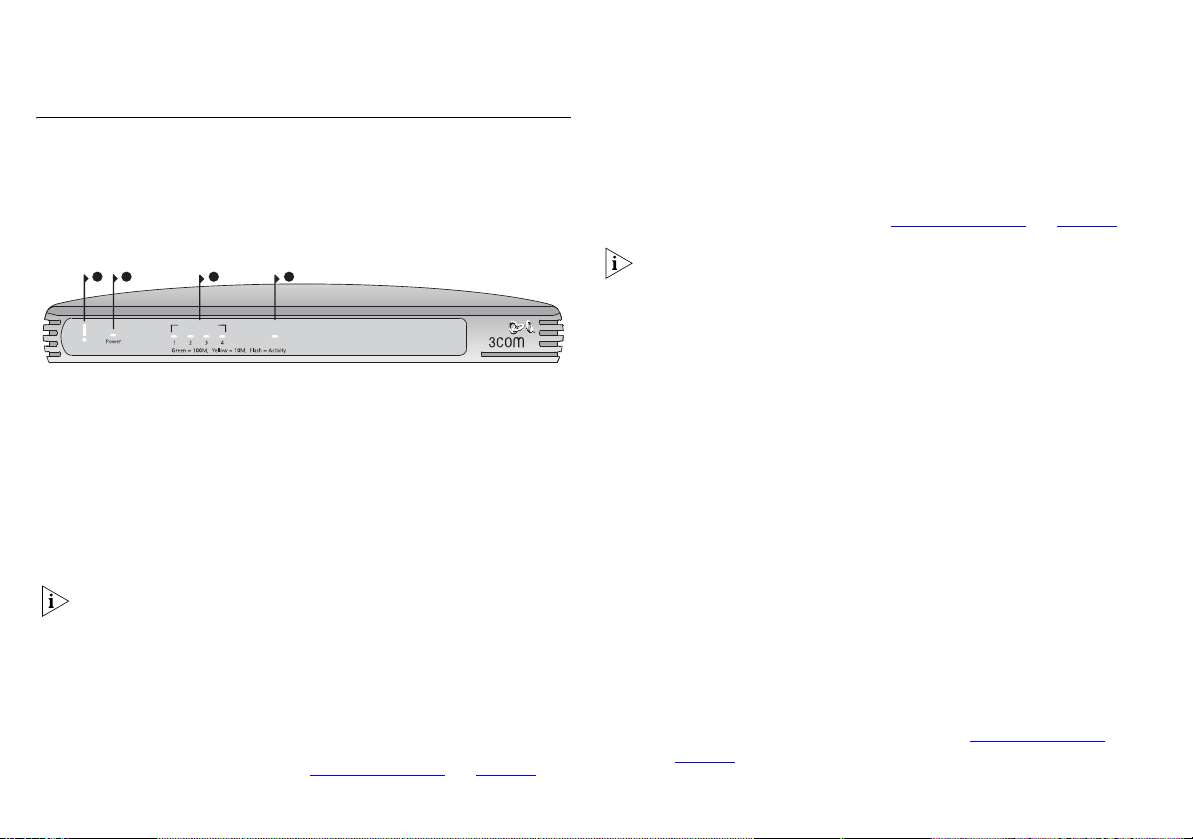
Front Panel
The front panel of the Secure Router contains a series of
indicator lights (LEDs) that help describe the state of various
networking and connection operations.
Figure 3 Secure Router - Front Panel
LAN Status
3
Cable/DSL
4
OfficeConnect Secure Router
OfficeConnect VPN Firewall
3CR870-95
3CR860-95
12
Alert
1 Alert LED (Orange)
Indicates a number of different conditions, as described below.
Off The Router is operating normally.
Flashing quickly Indicates one of the following conditions:
■ The Router has just been started up and is running a self-test
routine.
The Alert LED may continue to flash for one minute or longer,
depending on your network configuration.
On for 2 seconds, then off The Router has detected and
prevented a hacker from attacking your network from the
Internet.
Continuously on A fault has been detected with your Router
during the start-up process. See “
The Alert LED will be on for a period of between three and five
seconds during the power on self test. This is normal and no
cause for alarm.
Troubleshooting” on page 75.
2 Power LED (Green)
Indicates that the Router is powered on.
3 Four LAN Status LEDs
Green (100 Mbps link) / Yellow (10 Mbps link)
Indicates a number of different conditions, as described below.
On The link between the port and the next piece of network
equipment is OK.
Flashing The link is OK and data is being transmitted or
received.
■ The system software is in the process of being upgraded.
In each of these cases, wait until the Router has completed the
current operation and the alert LED is Off.
Flashing slowly The Firmware is corrupt or the Router has
booted in fail-safe mode. See “
Troubleshooting” on page 75.
Off Indicates one of the following
■ nothing is connected
■ the connected device is switched off
■ there is a problem with the connection. “Troubleshooting” on
page 75
.
12
Page 13
4 Cable/DSL Status LED
Green (100 Mbps link) / Yellow (10 Mbps link)
Indicates a number of different conditions, as described below.
On The link between the Router and the cable or DSL modem
is OK.
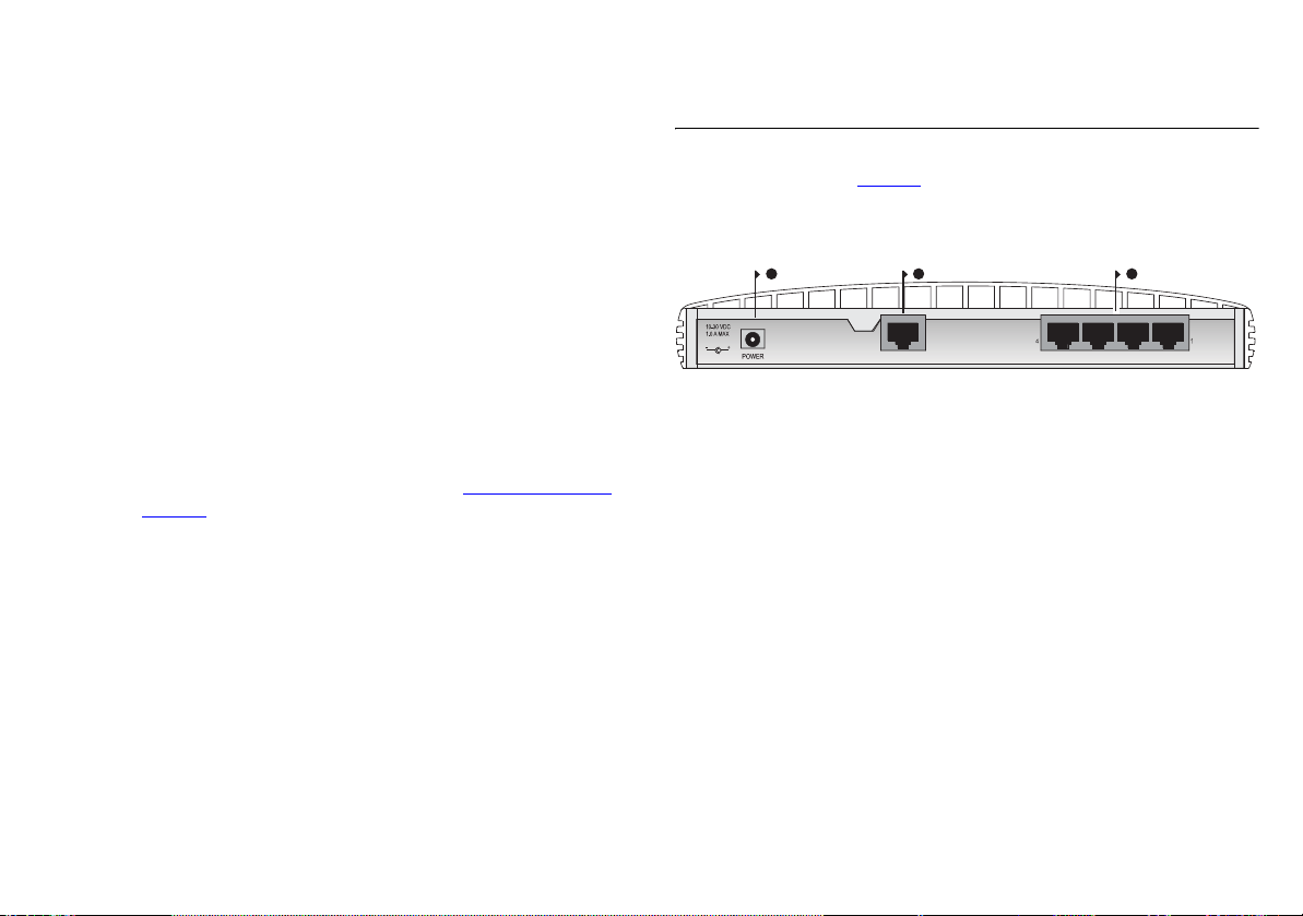
Rear Panel
The rear panel (Figure 4) of the Router contains four LAN ports,
one Ethernet Cable/DSL port, and a power adapter socket.
Figure 4 Secure Router - Rear Panel
675
Flashing The link is OK and data is being transmitted or
received.
Off Indicates one of the following
■ nothing is connected
■ the modem is switched off
■ there is a problem with the connection. “Troubleshooting” on
page 75
.
Ethernet
Cable/
DSL
5 Power Adapter socket
Only use the power adapter that is supplied with this Router. Do
not use any other adapter.
6 Ethernet Cable/DSL port
Use the supplied patch cable to connect the Router to the
10/100 port on your cable or DSL modem. This port will
automatically adjust for the correct speed, duplex and cable type.
You can connect your Cable/DSL modem using either
straight-through or crossover cables.
7 Four 10/100 LAN ports
Use suitable cable with RJ-45 connectors. You can connect your
Router to a computer, or to any other piece of equipment that
has an Ethernet connection (for example, a hub or a switch). All
ports will automatically adjust for the correct speed, duplex and
cable type. You can connect your Ethernet devices using either
straight-through or crossover cables.
13
LAN
Page 14

14
Page 15

INSTALLING THE ROUTER
Introduction
This chapter will guide you through a basic installation of the
OfficeConnect Secure Router, including:
■ Connecting the Router to the Internet.
■ Connecting the Router to your network.
Positioning the Router
You should place the Secure Router in a location that:
■ is conveniently located for connection to the cable or DSL
modem that will be used to connect to the Internet.
■ allows convenient connection to the computers that are to be
connected to the four LAN ports on the rear panel.
■ allows easy viewing of the front panel LED indicator lights,
and access to the rear panel connectors, if necessary.
Safety Information
WARNING: Please read the “Important Safety Information”
section before you start.
VORSICHT: Bitte lesen Sie den Abschnitt “Wichtige
Sicherheitsinformationen” sorgfältig durch, bevor Sie das Gerät
einschalten.
AVERTISSEMENT: Veuillez lire attentivement la section
“Consignes importantes de sécurité” avant de mettre en route.
When positioning your Router, ensure:
■ It is out of direct sunlight and away from sources of heat.
■ Cabling is away from power lines, fluorescent lighting fixtures,
and sources of electrical noise such as radios, transmitters and
broadband amplifiers.
■ Water or moisture cannot enter the case of the unit.
■ Air flow around the unit and through the vents in the side of
the case is not restricted. We recommend you provide a
minimum of 25mm (1in.) clearance.
Using the Rubber Feet
Use the four self-adhesive rubber feet to prevent your Router
from moving around on your desk or when stacking with flat top
OfficeConnect units. Only stick the feet to the marked areas at
each corner of the underside of your Routerl.
Using the Stacking Clip
The stacking clip allows you to stack your OfficeConnect units
together neatly and securely.
CAUTION: You can stack up to a maximum of four units. Smaller
units must be stacked above larger units.
To fit the clip:
1 Place your unit on a flat surface.
2 Fit the clip across the top of the unit, as shown in
Figure 5
(picture 1), ensuring that the longer sections of the
fastening pieces are pointing downwards.
3 Align the fastening pieces over the slots found on each side of
the unit.
15
Page 16
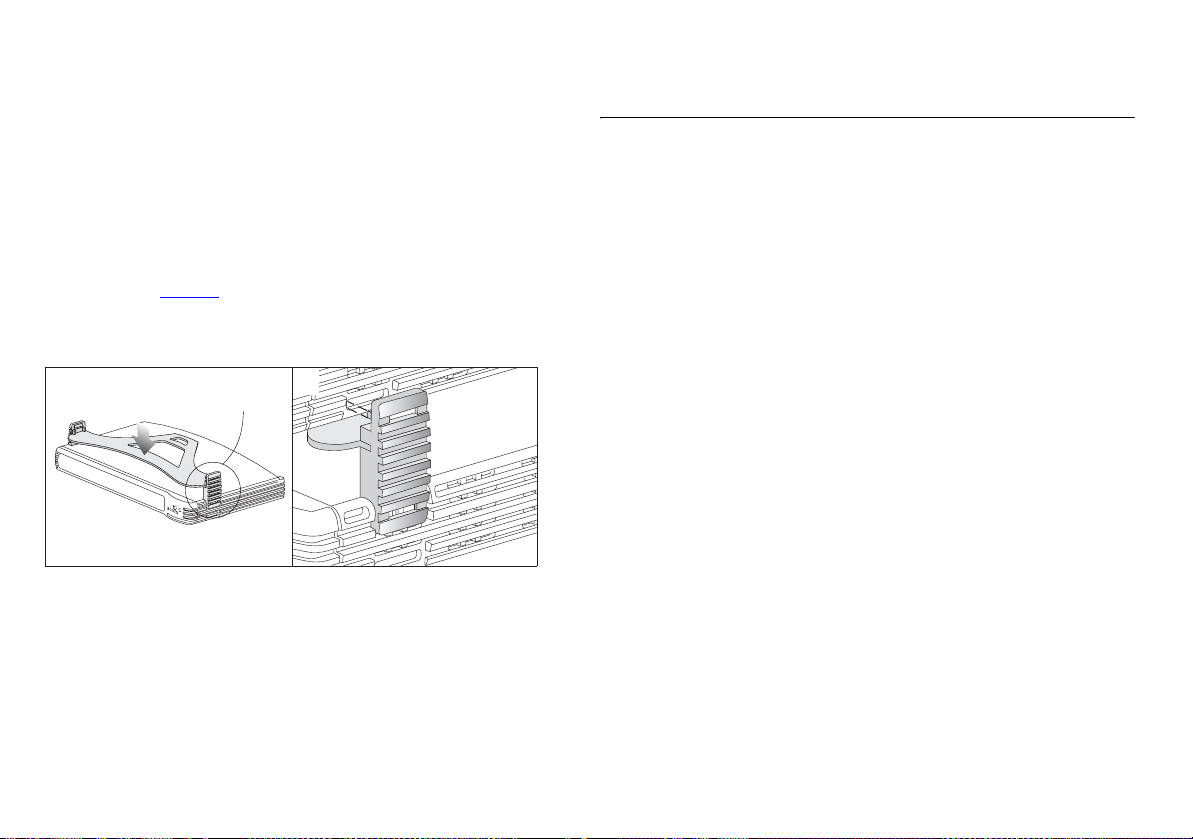
4 Push the clip down gently to secure it, ensuring the fastening
pieces snap into the slots on the unit.
To fit another unit:
1 Rest the second unit on top of the clip and align it with the front
of the unit below.
2 Press down gently on the unit to secure it onto the clip, ensuring
the fastening pieces fit into the slots on the unit below, as
shown in Figure 5
Figure 5 Stacking Your Units Together
1
(picture 2).
Fastening
Piece
2
Fastening
Piece
To remove the clip:
1 Remove the top unit together with the clip. If you hook a finger
around one of the the fastening pieces and then pull it gently
from out of the slot, the clip should come away with the upper
unit attached to it.
2 Push the clip in the center, so it bends towards the base of the
unit, and then separate once the clip is loose.
Before you Install your Router
Before you can configure the Router you need to know the IP
information allocation method used by your ISP. There are four
different ways that ISPs allocate IP information, as described
below:
Dynamic IP Address (DSL or Cable)
Dynamic IP addressing (or DHCP) automatically assigns the Router
IP information. This method is popular with Cable providers. This
method is also used if your modem has a built in DHCP server.
PPPoE (DSL only)
If the installation instructions that accompany your modem ask
you to install a PPPoE client on your PC then select this option.
Note that when you install the Router, you will not need to use
the PPPoE software on your PC. To configure the Router you will
need to know the following: Username, Password, and Service
Name (if required by your ISP).
Static IP Address (DSL or Cable)
The ISP provides the IP addressing information for you to enter
manually. To configure the Router you will need to know the
following: IP Address, Subnet Mask, ISP Gateway Address, and
DNS address(es).
PPTP (DSL or Cable)
PPTP is used by some providers, mostly in Europe. If the
installation instructions that accompany your modem ask you to
setup a dialup connection using a PPTP VPN tunnel then select
16
Page 17
this option. Note that when you install the Router, you will not
need to use the dialup VPN on your PC anymore. To configure
the Router you will need to know the following: Username,
Password, and VPN Server address (usually your modem). You will
be asked for the IP Allocation Mode when you run the Setup
Wizard.
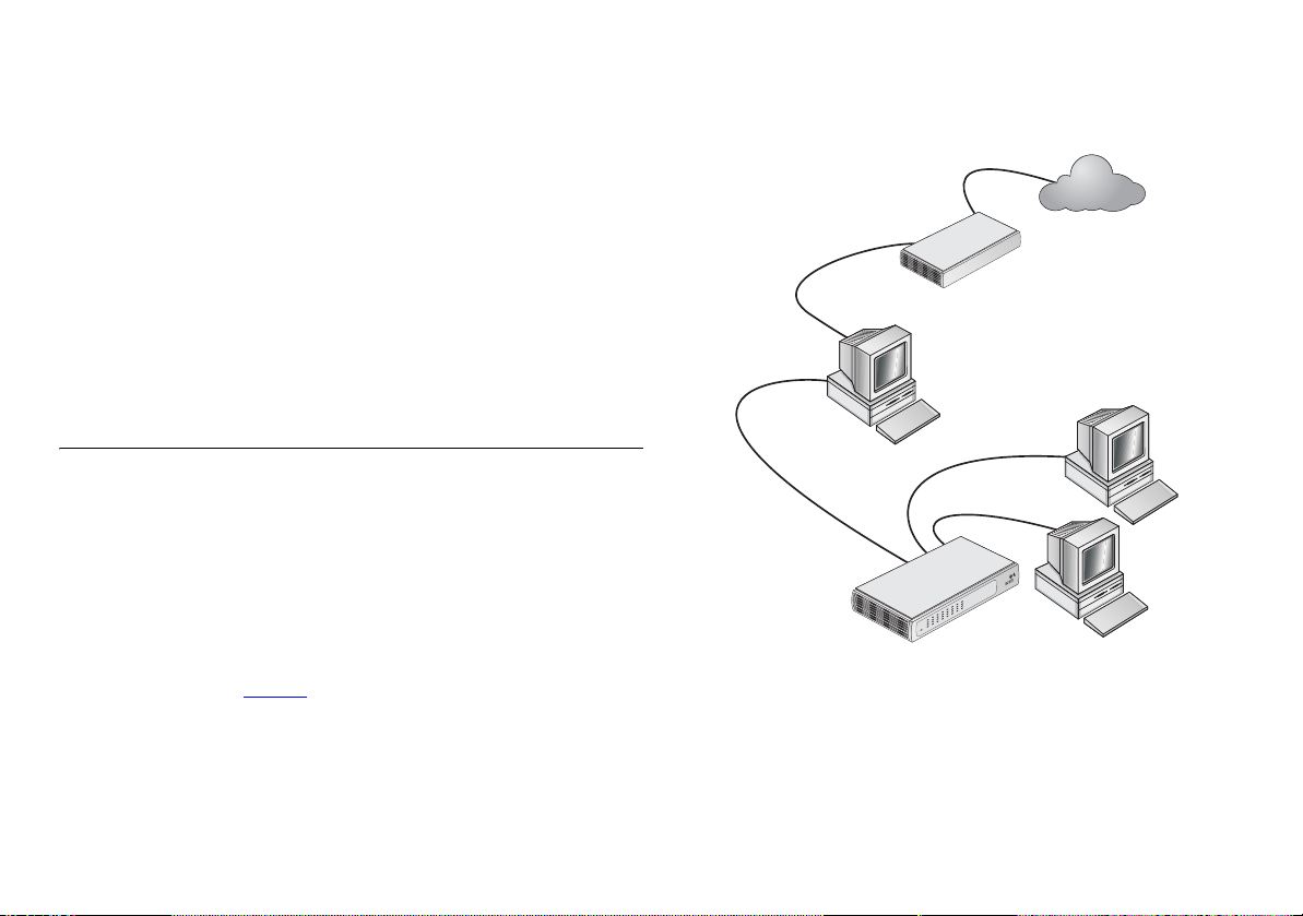
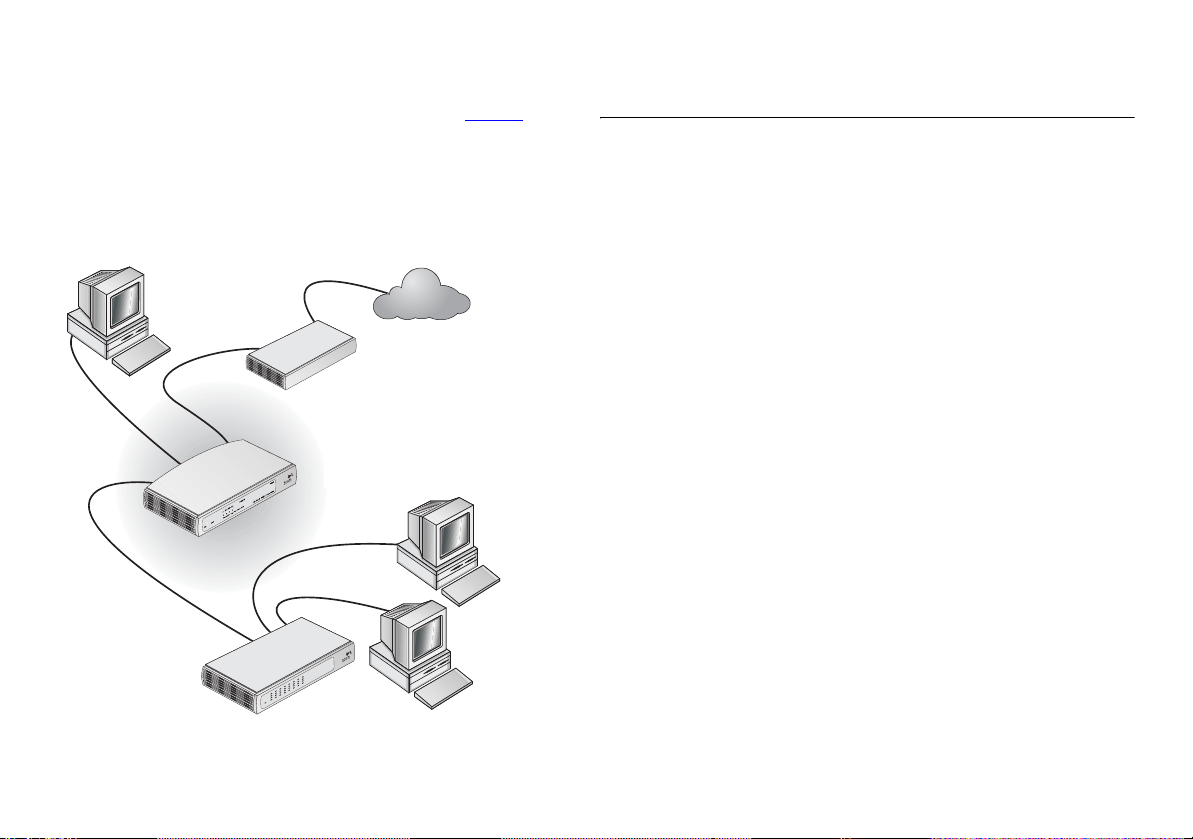
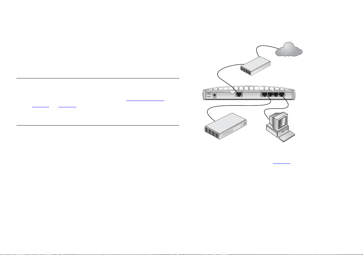
Figure 6 Connecting the Secure Router
Your existing
Cable/DSL
Modem
Internet
Powering Up the Router
1 Plug the power adapter into the power adapter socket located
on the back panel of the Router (refer to “
Power Adapter
socket” on page 13).
2 Plug the power adapter into a standard electrical wall socket.
Connecting the Secure Router
The first step for installing your Secure Router is to physically
connect it to a cable or DSL modem in order to be able to access
the Internet.
:
5
OfficeConnect
Switch
Ethernet
Cable/
DSL
LAN
OfficeConnect
OfficeConnect
VPN Firewall
Secure Router
To use your Secure Router to connect to the Internet through an
external cable or DSL modem (Figure 6
)
1 Use the supplied cable to connect the Router's Ethernet
Cable/DSL port to your Cable/DSL modem. Ensure that your
modem is connected to the Internet and switched on.
2 Connect your computer to one of the 10/100 LAN ports on the
Router.
17
Page 18

3 Connect the power adaptor to the Router and wait for the Alert
LED to stop flashing. Check that the Cable/DSL Status LED is
illuminated.
4 Switch on your computer. Once your computer is ready to use,
check that the LAN Port Status LED on the Router is illuminated.
You have now completed the hardware installation of your
Router. You now need to set up your computers so that they can
make use of the Router to communicate with the Internet.
18
Page 19
SETTING UP YOUR COMPUTERS
The OfficeConnect Secure Router has the ability to dynamically
allocate network addresses to the computers on your network,
using DHCP. However, your computers need to be configured
correctly for this to take place. To change the configuration of
your computers to allow this, follow the instructions in this
chapter.
If your computers are configured with static addresses (also
known as fixed addresses) and you do not wish to change this,
then you should use the Discovery program on the Router
CD-ROM to detect and configure your Router. Refer to “
Discovery” on page 79 for information on using the Discovery
program.
Obtaining an IP Address Automatically
Windows 2000, XP, 2003 Server
If you are using Windows 2000, Windows XP or Windows 2003
Server, use the following procedure to change your TCP/IP
settings (Windows XP and 2003 Server specific instructions in
brackets):
1 From the Windows Start Menu, select Settings > Control Panel
(select Control Panel directly from the Start menu in Windows
XP)
2 Double click on Network and Dial-Up Connections (Network and
Internet Connections). For XP and 2003 Server only — click on
Network Connections.
3 Double click on Local Area Connection.
Using
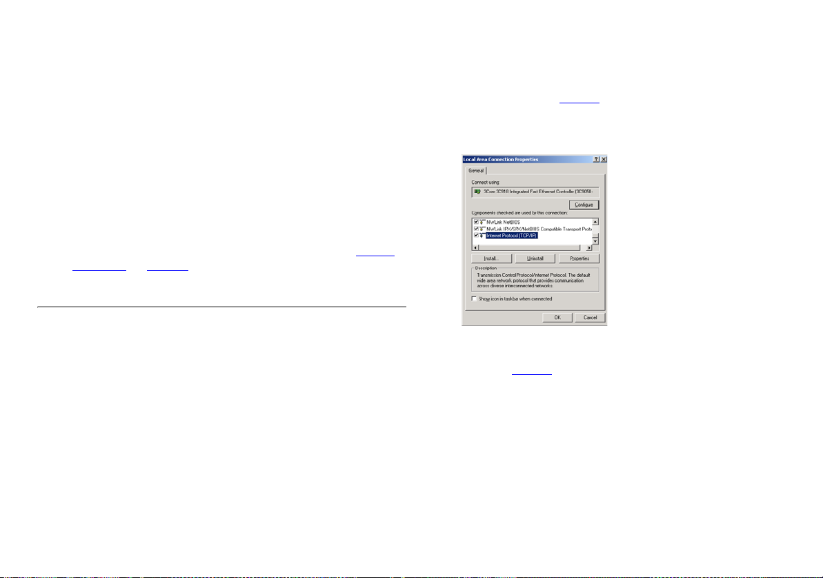
4 Click on Properties.
5 A screen similar to Figure 7 should be displayed. Select Internet
Protocol (TCP/IP) and click on Properties.
Figure 7 Local Area Connection Properties
6 Ensure that the options Obtain an IP Address automatically, and
Obtain DNS server address automatically are both selected as
shown in Figure 8
. Click OK.
19
Page 20
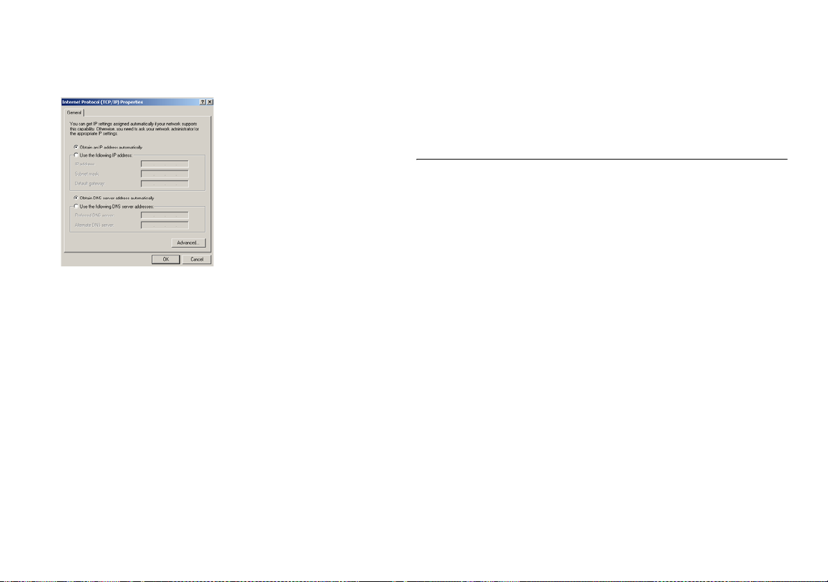
Figure 8 Internet Protocol Properties
7 Restart your computer.
Windows 95, 98
1 From the Windows Start Menu, select Settings > Control Panel.
2 Double click on Network. Select the TCP/IP item for your network
card and click on Properties.
3 In the TCP/IP dialog, select the IP Address tab, and ensure that
Obtain IP address automatically is selected. Click OK.
4 Restart your computer.
Macintosh OS 8.5, 9.x
If you are using a Macintosh computer, use the following
procedure to change your TCP/IP settings:
3 In the TCP/IP control panel, set Configure: to “Using DHCP
Server.”
4 Close the TCP/IP dialog box, and save your changes.
5 Restart your computer.
Disabling PPPoE and PPTP Client Software
If you have PPPoE or PPTP client software installed on your
computer, you will need to disable it. To do this:
1 From the Windows Start menu, select Settings > Control Panel.
2 Double click on Internet Options.
3 Select the Connections Tab. A screen similar to Figure 9 should
be displayed.
4 Select the Never Dial a Connection option and click OK.
1 From the desktop, select Apple Menu, Control Panels, and TCP/IP.
2 In the TCP/IP control panel, set Connect Via: to “Ethernet.”
20
Page 21
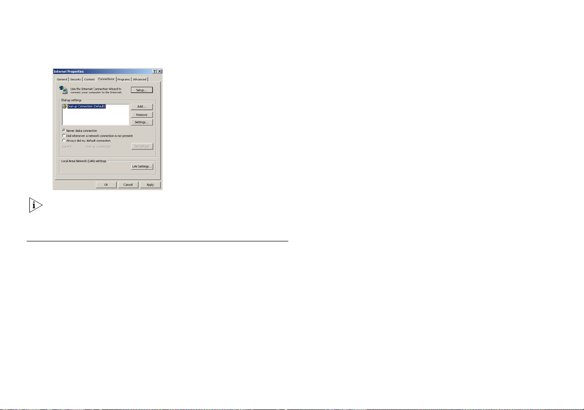
Figure 9 Internet Properties
You may wish to remove the PPPoE client software from your
computer to free resources, as it is not required for use with the
Router.
Disabling Web Proxy
Ensure that you do not have a web proxy enabled on your
computer.
Go to the Control Panel and click on Internet Options. Select the
Connections tab and click on LAN Settings at the bottom. Make
sure that the Use Proxy Server option is unchecked.
21
Page 22

22
Page 23

RUNNING THE SETUP WIZARD
If the Router needs to be configured, for example if it has not
yet been used or has been reset, it will run the Setup Wizard
automatically. This detects some of the settings the Router needs
to function and asks that you input the others.
Accessing the Wizard
The Secure Router Setup Wizard is Web-based, which means that
it is accessed through your Web browser (Netscape Navigator or
Internet Explorer).
To use the Setup Wizard:
1 Ensure that you have at least one computer connected to the
Router. See “
2 Launch your Web browser on the computer. Enter the URL of
your Router in to the location or address box of your browser
(Figure 10
The default URL for the Router is http://192.168.1.1. If you have
changed the IP address of the unit you should substitute this for
the default address within the URL.
Figure 10 Web Browser Location Field (Factory Default)
Installing the Router” on page 15.
).
The Login screen, as shown in Figure 11, should appear in your
browser. If it does not, refer to “
3 To log in, enter the password (the default password is admin) in
the System Password field and click Log in.
Figure 11 Login Screen
4 If the password is correct, the OfficeConnect Secure Router
Welcome screen, shown in Figure 12
has not been configured before, the Wizard, shown in Figure 13,
will also launch automatically.
Troubleshooting” on page 75.
, will appear. If your Router
23
Page 24
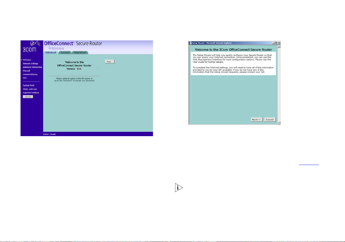
Figure 12 Welcome Screen
If the Wizard does not launch automatically (this may occur if the
Router has been powered up or configured previously) you can
launch the Wizard manually.
5 To launch the Wizard manually click on the Setup Wizard tab in
the welcome screen followed by the WIZARD... button.
Figure 13 Wizard Screen
Click Next to continue.
You will now be guided through the setup of your Router.
Setting the Password
When the Change Administration Password screen (Figure 14)
appears, type the Old Password, then a new password in both
the New Password and Confirm Password fields.
The default password for the Router is ‘admin’. It is case sensitive
and must be entered as the Old Password the first time you
configure the Router. 3Com recommends that you change the
password from its default value.
24
Page 25
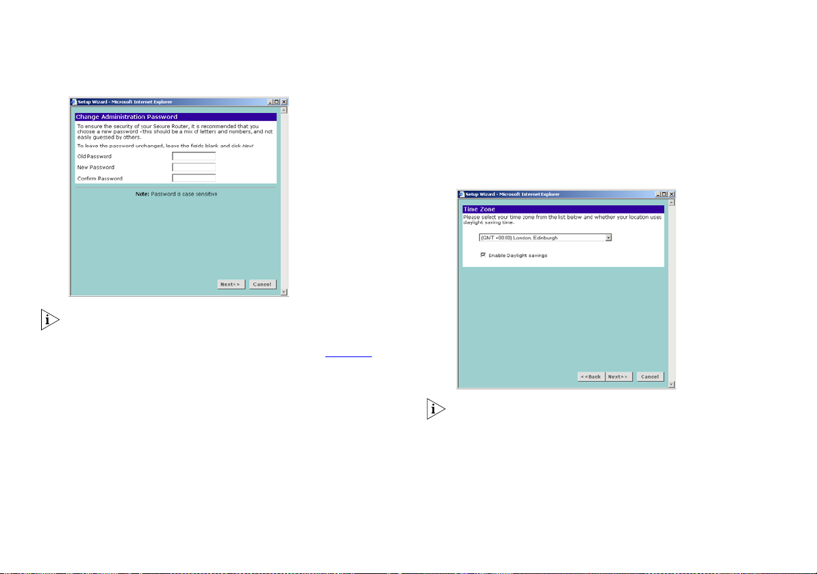
Figure 14 Change Administration Password Screen
Choose a password that you can remember but that others are
unlikely to guess. Remember that the password is case sensitive.
To set the Router to World Time (UTC):
1 Select (GMT) Greenwich Mean Time from the drop-down menu.
2 Ensure that the Enable Daylight Saving box is cleared.
3 Click Next to continue.
Figure 15 Time Zone Screen
Click Next to display the Time Zone setup screen (Figure 15
Setting the Time Zone
The Router sets its time automatically when it connects to the
Internet. This time is used when recording information log files.
To set the Router to your local time:
1 Select your time zone from the drop-down menu.
2 Check the Enable Daylight Saving box to automatically adjust the
time seasonally.
3 Click Next to continue.
).
The Daylight Savings option automatically adjusts the system
clock for summer and winter time. To disable this feature ensure
that the Enable Daylight Saving box is cleared.
25
Page 26
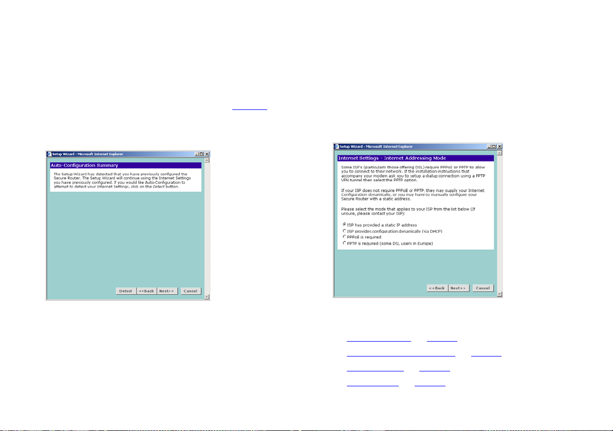
Auto-Configuration Settings
If the Router is able to detect a PPPoE or DHCP server on its
Ethernet Cable/DSL port then it will offer you the option of
configuring its Internet settings automatically. As an example, the
Auto-Configuration screen for PPPoE is shown in Figure 16
below.
Figure 16 PPPoE Auto-configuration Screen
Internet Settings
The Internet Settings window allows you to set up the Router for
the type of Internet connection you have. Before setting up your
Internet connection mode, have the modem configuration
supplied by your ISP to hand.
Figure 17 Internet Settings Screen
Click Next to accept the option you have chosen and continue.
■ If the Router could not automatically configure your internet
settings or if you chose to configure your Internet settings
manually, continue at “Internet Settings” below.
■ If you chose one of the automatic configuration options
continue at “Choosing your LAN Settings” on page 29.
Select the Internet Addressing mode your ISP requires and click
Next. Depending on your selection, refer to:
■ “Static IP Mode” on page 27
■ “Dynamic IP Address Mode” on page 27
■ “PPPoE Mode” on page 28,
■ “PPTP Mode” on page 29.
26
Page 27
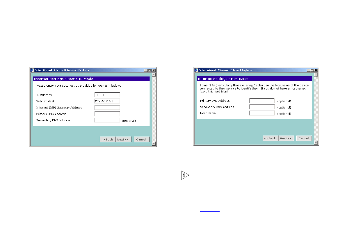
Static IP Mode
To setup the Router for use with a static IP address connection,
use the following procedure:
Dynamic IP Address Mode
To setup the Router for use with a dynamic IP address
connection:
Figure 18 Static IP Mode Screen
1 Enter your IP Address in the IP Address text box.
2 Enter your subnet mask in the Subnet Mask text box.
3 Enter your ISP Gateway address in the Internet (ISP) Gateway
Address text box.
4 Enter your primary DNS address in the Primary DNS Address text
box.
5 If your ISP provides a secondary DNS address, enter it in the
Secondary DNS Address text box, otherwise leave the box blank.
6 Click Next to continue.
Figure 19 Hostname Screen
1 If your ISP requires the addresses of a Primary and Secondary
DNS Server then enter them in the fields labelled Primary DNS
Address and Secondary DNS Address.
If your ISP does not require one of the fields to be filled in then
leave it blank.
2 If your ISP requires you to supply a host name enter it in the Host
Name box, otherwise leave the box blank.
3 Click Next to continue to the Clone MAC Address screen, shown
in Figure 20
below.
27
Page 28
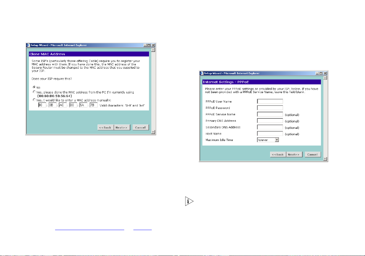
Figure 20 Clone MAC Address Screen
4 If your ISP requires an assigned MAC address, select the
appropriate radio button:
■ Yes, please clone the MAC address from the PC I’m currently
using if the computer you are using now is the one that was
previously connected directly to the cable or DSL modem.
■ Yes, I would like to enter a MAC address manually and
manually enter the values for a MAC address if the computer
you are using now was not previously connected directly to
the cable or DSL modem.
Otherwise select No.
5 Click Next to continue
Continue at “
Choosing your LAN Settings” on page 30.
PPPoE Mode
To setup the Router for use with a PPP over Ethernet (PPPoE)
connection, use the following procedure:
Figure 21 PPPoE Screen
1 Enter your PPP over Ethernet user name in the PPPoE User Name
text box.
2 Enter your PPP over Ethernet password in the PPPoE Password
text box.
If your ISP does not require one of the fields to be filled in then
leave it blank.
3 If your ISP requires you to supply a PPPoE service name, enter it
in the PPPoE Service Name text box.
28
Page 29
4 If your ISP requires the addresses of a Primary and Secondary
DNS Server then enter them in the fields labelled Primary DNS
Address and Secondary DNS Address.
5 If your ISP requires you to supply a host name enter it in the Host
Name box, otherwise leave the box blank.
6 If your ISP charges for connection time then you may wish to set
the Maximum Idle time to control costs. The Maximum Idle Time
is the amount of time without activity before the Router
terminates the Internet connection. By default the value will be
forever.
7 Click Next to continue.
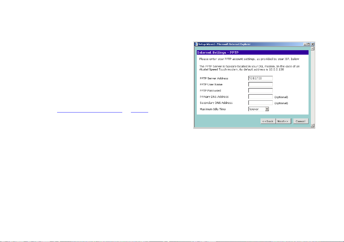
Figure 22 PPTP Screen
Continue at “
Choosing your LAN Settings” on page 30.
PPTP Mode
To setup the Router for use with a PPTP connection, use the
following procedure:
1 Enter your PPTP server address in the PPTP Server Address text
box.
2 Enter your PPTP user name in the PPTP User Name text box.
3 Enter your PPTP password in the PPTP Password text box.
4 If your ISP requires the address of a Primary DNS Server then
enter it in the field labelled Primary DNS Address.
5 If your ISP requires the address of a Secondary DNS Server then
enter it in the field labelled Secondary DNS Address, otherwise
leave the box blank.
6 If you wish to set maximum idle time enter it in the Maximum
Idle Time box, otherwise leave the box blank. If your ISP charges
for connection time then you may wish to set the Maximum Idle
time to control costs. The Maximum Idle Time is the amount of
29
Page 30
time without activity before the Router terminates the Internet
connection. By default the value will be forever.
7 Check all your settings, and then click Next.
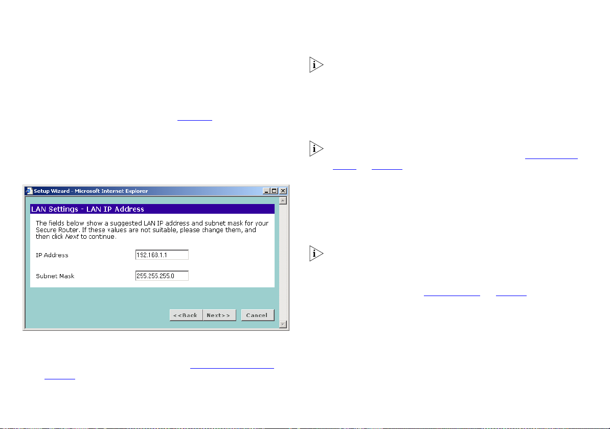
Choosing your LAN Settings
The LAN settings screen, shown in Figure 23 below, displays the
Router’s current IP address and subnet mask. If this is the first
time the Wizard has been run it will display the default address
and subnet mask.
Figure 23 LAN IP Address Screen
1 Enter your chosen IP address for the Router in the IP Address
field. This should be a private network so that it does not conflict
with IP addresses on the Internet. See “
page 83
.
Private IP Addresses” on
3Com recommends that you use the default IP address and
subnet mask unless you already have a network that uses
different values.
2 Enter your chosen subnet mask in the Subnet Mask field. This
should be large enough to contain all your computers and other
network devices. The default (255.255.255.0) allows for 254
devices including the Router.
3 If you are going to set up an IPSec VPN with another Router you
must set your subnet mask to 255.255.255.0. See “
Configuring
VPNs” on page 58.
Activating DHCP
The Router contains a Dynamic Host Configuration (DHCP) server
that can automatically configure the TCP/IP settings of every
computer on your network. The DHCP Server Setup screen is
shown below.
If you intend to use the Router to control the permissions of
individual machines on your network then you must use the
Router’s DHCP server to allocate addresses (or use static
addressing). If you use another DHCP server you may get
unexpected results. See “
PC Privileges” on page 50.
30
Page 31

Figure 24 DHCP Server Setup Screen
3Com recommends that you activate the DHCP server and leave
it at the default values unless you already have a DHCP Server on
your network.
■ To activate the DHCP Server option, select Enable the DHCP
server with the following settings:. The DHCP server will
default to the addresses 192.168.1.100 to 192.168.1.200 if
the IP address of the Router has been left at the default
192.168.1.1.
The Setup Wizard suggests a DHCP server address range that is
valid for the LAN settings entered. If the defaults are used it will
be 100 - 200. The suggested range will vary depending on the
LAN settings entered in the LAN IP Address screen.
■ To disable DHCP, select Do not enable the DHCP server.
Viewing the Summary
When you complete the Setup Wizard, a configuration summary
will display. See Figure 25
information of the Router and click Finish to save your settings
and restart the Router.
Figure 25 Configuration Summary Screen
3Com recommends that you print the Configuration Summary
screen for your records.
If you have changed the IP address of your Router your computer
will need to change its IP address to communicate with the
Router. Reboot your computer once the Router has restarted to
get a new address.
below. Verify the configuration
Click Next when you have finished.
31
Page 32

If want to make changes, click the Back button until you reach
the screen which contains the settings you want to change and
follow the instructions from that point.
Your Router is now configured.
You can start using your Router straight away or further
configure your Router (see “
Router Configuration” on page 33).
32
Page 33

ROUTER CONFIGURATION
This chapter describes all the options available through the
Router configuration pages, and is provided as a reference.
Navigating Through the Router Configuration Pages
To get to the configuration pages, browse to the Router by
entering the URL in the location bar of your browser. The default
URL is http://192.168.1.1. If you changed the Router LAN
IP address during initial configuration, use the new IP address
instead. When you have browsed to the Router, log in using your
system password. The default password is ‘admin’.
Main Menu
At the left side of all screens is a main menu, as shown in
Figure 26
page will appear in the main part of the screen.
Figure 26 OfficeConnect Secure Router Screen Layout
■ Welcome — displays the firmware version of the Router and
. When you click on a topic from the main menu, that
Option Tabs
Main Menu
important messages on the Notice Board, allows you to
change your password, and launch the Wizard.
■ Network Settings — allows you to set up Internet addressing
modes such as PPPoE connection, dynamic IP address
allocation and static IP address settings. Also allows you to
configure LAN IP address and subnet mask information, set
up DHCP server parameters, and display the DHCP client list.
■ Advanced Networking — allows you to set up Network
Address Translation (NAT), static routing, dynamic routing, and
dynamic DNS.
■ Firewall — allows configuration of the Router’s firewall
features: Virtual Servers, Special Applications, PC Privileges
and other general security options.
■ Content Filtering — allows control of access to web sites on
the internet.
■ VPN — Allows the administrator to set up and maintain
Virtual Private Network (VPN) connections.
■ System Tools — allows the administrator to perform
maintenance activities on the Router.
■ Status and Logs — displays the current status and activity logs
of the Router.
■ Support/Feedback — contains a comprehensive online help
system and 3Com contact information.
Option Tabs
Each menu page may also provide sub-sections which are
accessed through the use of option tabs (see Figure 26
example). To access an option, simply click on the required tab.
for
33
Page 34

Getting Help
On every screen, a Help button is available that provides access
to the context-sensitive online help system. Click this button for
further assistance and guidance relating to the current screen.
Welcome Screen
The Welcome section allows you to view the Notice board and to
change your Password. You can also gain access to the
Configuration Wizard. See “
for details.
Viewing the Notice Board
The Notice Board, shown in Figure 27 below, is used to display
important messages. For example, you would be warned if you
had disabled the firewall feature or if the LAN and Internet
addresses or subnets conflicted.
Accessing the Wizard” on page 23
Figure 27 Notice Board Screen
34
Page 35

Changing the Administration Password
You should change the password to prevent unauthorized access
to the Administration System.
Figure 28 Password Screen
To change the password:
1 Enter the current password in the Old Password field.
2 Enter the new password in the New Password field.
3 Enter the new password again in the Confirm Password field.
4 Click Apply to save the new password.
The password is case sensitive.
Setup Wizard
Figure 29 Wizard Screen
Click the WIZARD... button to launch the configuration wizard.
Refer to “
Running the Setup Wizard” on page 23 for information
on how to run the wizard.
Network Settings
The Network Settings menu allows you to view and amend your
Router’s:
■ Connection to ISP.
■ LAN settings.
■ DHCP Clients list.
35
Page 36

Connection to ISP
This option, shown in Figure 30, allows you to change the
method your Router uses to connect to your ISP. You should only
need to change these settings if:
■ you change your Internet connection password (PPPoE only),
or
■ your ISP informs you of a change in their settings or you
change ISPs.
Figure 30 Connection to ISP Screen
Select the addressing method that your ISP uses to allocate your
Router’s Internet IP address. Choose from the options in the IP
Allocation Mode drop-down box and the screen will refresh with
options relevant to that choice.
■ If you select Static IP address (to be specified manually) see
“
Configuring a Static IP Address” on page 37.
■ If you select Dynamic IP address (automatically allocated) see
“
Configuring a Dynamic IP Address” on page 38.
■ If you select PPPoE (PPP over Ethernet) see “Configuring a
PPPoE connection” on page 39.
■ If you select PPTP (used by some providers, mostly in Europe)
see “
Configuring a PPTP connection” on page 40.
If you are using One to One NAT your method of connection will
already be fixed to Static. To change to another method of
address allocation you must first turn off One to One NAT. See
“
Setting up NAT” on page 44.
Before you can configure the Router, you need to know the IP
information allocation method used by your ISP. There are four
different ways that ISPs can allocate IP information, as described
below.
When you install the Router, you will not need to use the PPPoE
software on your PC.
When you install the Router, you will not need to use the dialup
VPN on your PC anymore.
The Router will automatically ‘dial on demand’ PPPoE or PPTP
and obtain date/time via NTP.
36
Page 37

■ Static IP Address (DSL or Cable)
The ISP provides the IP addressing information for you to
enter manually. To configure the Router you will need to
know the following:
■ IP address
■ Subnet Mask
■ ISP Gateway address
■ DNS address(es)
■ Dynamic IP Address (DSL or Cable)
Dynamic IP addressing (or DHCP) automatically assigns the
Router IP information. This method is popular with Cable providers. This method is also used if your modem has a built in
DHCP server.
■ PPPoE (DSL only)
PIf the installation instructions that accompany your modem
ask you to install a PPPoE client on your PC, then select this
option. To configure the Router you will need to know the
following:
■ Username
■ Password
■ Service Name (if required by your ISP)
■ PPTP (DSL or Cable)
PPTP is used by some providers, mostly in Europe. If the installation instructions that accompany your modem ask you to
setup a dialup connection using a PPTP VPN tunnel then
select this option. To configure the Router you will need to
know the following:
■ Username
■ Password
■ VPN server address (usually your modem).
Configuring a Static IP Address
If your ISP has allocated you one or more static addresses you
will have selected Static IP address (to be specified manually) as
your IP Allocation Mode.
Figure 31 Static Address Setup Screen
37
Page 38

The following settings are required to set up Static IP address
connection. Enter the values provided by your ISP:
■ IP Address — The address allocated by your ISP for this
connection.
If you have been allocated a range of IP addresses by your ISP
enter the first IP address in the range.
■ Subnet Mask — The subnet mask supplied by your ISP for this
connection.
■ ISP Gateway Address — The Gateway address from your ISP
to the Internet.
■ Primary DNS Address — The address of your ISP’s Domain
Name Service server.
■ Secondary DNS Address — The address of your ISP’s
secondary Domain Name Service server. The second server is
optionally provided by an ISP in case of failure of the primary
server.
Click Apply to save any changes you have made.
Configuring a Dynamic IP Address
If your ISP has allocated you a dynamic address using DHCP you
will have selected Dynamic IP address (automatically allocated) as
your IP Allocation Mode.
Figure 32 Dynamic Address Setup Screen
To setup the Router for use with a dynamic IP address connection
the following settings are configured:
■ IP Address — The internet address allocated by your ISP for
this connection is automatically configured and is not
editable.
38
Page 39

■ Subnet Mask — The subnet for the address is automatically
configured but is not displayed.
■ ISP Gateway Address — The Gateway address from your ISP
to the Internet is automatically configured but is not
displayed.
■ Primary DNS Address — If your ISP requires the address of a
Primary DNS Server then enter it in the field labelled Primary
DNS Address.
■ Secondary DNS Address — If your ISP requires the address of
a Secondary DNS Server then enter it in the field labelled
Secondary DNS Address, otherwise leave the box blank.
■ Host Name — The Host Name of your computer may be
required by your ISP.
■ Clone MAC Address — Your ISP may require you to have a
particular MAC address. This will be the MAC address of the
computer you first used to connect with your ISP.
Click Apply to save any changes you have made.
Configuring a PPPoE connection
If your ISP has allocated you a dynamic address using PPPoE you
will have selected PPPoE (PPP over Ethernet) as your IP Allocation
Mode.
Figure 33 PPPoE Setup Screen
Your ISP may need you to enter host name or PPPoE settings. To
setup the Router for use with a PPPoE connection the following
fields will need to be completed:
■ IP Address — The internet address allocated by your ISP for
this connection is automatically configured and is not
editable.
■ PPPoE User Name — The user name you use to access your
ISP.
39
Page 40

■ PPPoE Password — The password you use to access your ISP.
■ PPPoE Service Name — Your ISP may require you to specify a
service name for your connection.
■ Primary DNS Address — If your ISP requires the address of a
Primary DNS Server then enter it in the field labelled Primary
DNS Address.
■ Secondary DNS Address — If your ISP requires the address of
a Secondary DNS Server then enter it in the field labelled
Secondary DNS Address, otherwise leave the box blank.
■ Host Name — The Host Name of your computer may be
required by your ISP.
■ Maximum Idle Time — The amount of time without activity
before the Router terminates the Internet connection.
Since the Router firmware contains its own PPPoE client, you no
longer need to run PPPoE client software on your computer to
access the Internet. You can simply start your browser and
connect to the Internet immediately after setting up your cable
or DSL modem.
Configuring a PPTP connection
If your ISP has allocated you a dynamic address using PPTP you
will have selected PPTP (used by some European providers) as
your IP Allocation Mode.
Figure 34 PPTP Setup Screen
To setup the Router for use with a PPTP connection the following
fields will need to be completed.
■ IP Address — The internet address allocated by your ISP for
this connection is automatically configured and is not
editable.
■ PPTP Server Address - This is typically the address of your
modem.
40
Page 41

■ PPTP User Name - The user name you use to access your ISP.
■ PPTP Password - The password you use to access your ISP.
■ Primary DNS Address — If your ISP requires the address of a
Primary DNS Server then enter it in the field labelled Primary
DNS Address.
■ Secondary DNS Address — If your ISP requires the address of
a Secondary DNS Server then enter it in the field labelled
Secondary DNS Address, otherwise leave the box blank.
■ Maximum Idle Time - The amount of time without activity
before the Router terminates the Internet connection.
Initial IP Address and Initial Subnet Mask - IP settings must be
used when establishing a PPTP connection. Alternatively, if the
PPTP server is located in your DSL modem, click Suggest to select
an IP address on the same subnet as the PPTP server.
LAN Settings
The LAN Settings screen allows you to change the TCP/IP settings
of your Router and its DHCP server.
Figure 35 Unit Configuration Screen
Changing the LAN Settings
These settings will have been entered during the set-up wizard
when the device is first used. You only need to change these if
you reconfigure your network. If you make any changes, click
Apply to save them to the Router.
When changing the IP Address of the Router choose an address
that will be unique in your network and in your network’s
subnet. The default IP Address of the Router is 192.168.1.1.
When you change the IP Address of the Router you must reboot
all computers that gain their IP address from the Router before
they will be able to access the Internet.
41
Page 42

If you are using static addresses for your PCs you must alter the
network configuration on each PC so that they have an IP
address within the same subnet as the Router and have their
default Gateway set as the Router’s LAN IP address.
If you reconfigure your network you may need to change your
Subnet Mask. The Subnet Mask detemines how many addresses
are available to your network. The default Subnet Mask is
255.255.255.0.
For example if the IP Address of your Router is 192.168.1.1 and
the Subnet Mask of your network is 255.255.255.0 then your
network can have a maximum of 254 addresses from
192.168.1.1 to 192.168.1.254 (192.168.1.0 and 192.168.1.255
are reserved by the subnet and are not available for use).
When you change the IP Address or Subnet Mask of the Router
you should review the DHCP Server settings as described below.
Changing the DHCP Server Settings
This section allows to you enable, disable and configure the
settings of the Router’s DHCP server.
If you intend to use the Router to control the permissions of
individual machines on your network then you must use the
Router’s DHCP server to allocate addresses (or use static
addressing). If you use another DHCP server you may get
unexpected results. See “
To enable the DHCP Server ensure that the Enable check box is
ticked. To disable the DHCP Server ensure that the Enable check
box is cleared. Click Apply to validate your changes.
PC Privileges” on page 50.
Set the IP Pool Start Address and IP Pool End Address to the first
and last address you want the Router to allocate to computers.
The IP address pool must be contained within the subnet as
defined in “Changing the LAN Settings” on page 41. The default
start and end addresses are 192.168.1.100 and 192.168.1.200.
The Local Domain Server is set to Domain as default.
If you have a WINS Server on your network enter its IP address in
the WINS Server box. The Router will pass this information on to
all Windows PCs that obtain an address from its DHCP server.
If you have a 3Com NBX Call Processor on your network enter its
IP address in the 3Com NBX Call Processor box. The 3Com NBX
Call Processor acts as a switchboard for voice-over-IP phones and
the Router will pass on this information.
If you will be using One-to-One NAT you must set up a range
that is one less than the number of public addresses allocated to
you by your ISP. The DHCP range must also be identical to the
range specified when you set up One-to-One NAT. See “
up One-to-One NAT” on page 45.
DHCP Clients List
The DHCP Clients List screen provides details of the devices that
have been given IP addresses by the Router’s DHCP server. For
each device that has been granted a lease, the IP address, Host
Name and MAC address of that device is displayed.
Setting
42
Page 43

Figure 36 DHCP Clients Screen
The Router grants leases for 7 days. If a computer does not
connect for a week, its IP Address may be reused.
The Router will attempt to supply a computer the same lease as
was issued previously, even if that lease has expired.
Expired leases are only reused when there are no free leases
available. When an expired lease is re-issued the oldest lease that
is not a fixed association is used.
The Release button allows the lease for an IP address that has
been issued to a device to be cleared. If you are running short of
addresses in the DHCP Pool and you know of computers that are
unlikely to connect to your network soon you can release the IP
address allowing it to be reallocated to another machine.
If you have spare or expired IP addresses in the pool you will not
need to release addresses.
The IP Address, Host Name and MAC Address indicate the
address that has been allocated. They identify the machine by
name and by the unique number (MAC Address) of the
machine’s network card.
The Fixed Association check box allows you to freeze the
relationship between an IP address and a particular machine. If
you check the box for one row, that IP address will always be
given out to the same machine and will not be allocated to
another machine even if the lease has expired. Clear the check
box to allow the address to revert back to normal behavior.
Click Refresh to save any changes you have made.
Click New to allocate an IP address to a MAC address. Click Add
to save.
Figure 37 Fixed DHCP Mapping Screen
43
Page 44

Advanced Networking
Setting up NAT
The Router is able to perform Network Address Translation (NAT)
in one of two modes as shown in Figure 38
■ One-to-many NAT — The Router shows only one address to
the Internet.
■ One-to-one NAT — Every address on the Internet pool is
linked to an address in the LAN pool. The Router will respond
to all the addresses in the Internet pool.
:
Figure 38 One-to-Many and One-to-One NAT
One-to-Many NAT
172.16.57.52
192.168.1.100
192.168.1.101
192.168.1.102
One-to-One NAT
172.16.57.52
172.16.57.53
172.16.57.54
192.168.1.100
192.168.1.101
192.168.1.102
44
Page 45

Setting up One-to-Many NAT
Figure 39 Network Address Translation Screen
This is very easy to set up and is the Router’s default mode. It
works with any IP Allocation Mode and will map all the
addresses on your LAN to the Internet address of your Router. To
set up One-to-Many NAT:
1 Select One-to-Many NAT from the NAT Mode drop-down box.
2 Click Apply to save your changes.
Setting up One-to-One NAT
The following criteria must be met to be able to use One-to-One
NAT:
■ You must have a static Internet IP address for every computer
on your network plus one for the Router itself.
■ The addresses must be in one continuous block in the same
subnet
■ You must have selected Static IP Address as your IP Allocation
Mode and have given your Router the first of the Internet
addresses allocated by your ISP.
Figure 40 One-to-One NAT Screen
45
Page 46

To set up One-to-One NAT:
1 Select One-to-One NAT from the NAT Mode drop-down box.
2 Enter the second address of your Internet range of addresses in
the First IP Address in ISP Pool field.
3 Enter the first address in your LAN range of addresses to which
you want to map this range in the First IP Address in LAN Pool
field.
3Com recommends that you set your DHCP pool to the same as
the range of LAN addresses used as your LAN pool.
4 Enter the number of addresses in the range into the Pool Size
field.
5 Click Apply to save your changes.
Static Routing
Setting up Static Routing
The Router supports up to 10 static routes in total, shared
between LAN and WAN interfaces. WAN side static routes are
only available if the mode of connection to your ISP is Static or
Dynamic (DHCP Client mode).
To set up Static Routing:
1 Select New on the right side of the screen to open the Static
Routing configuration dialogue box.
2 Enter the IP address of the Destination Network (e.g.
192.168.20.0).
3 Enter the IP address of the Subnet Mask (e.g. 255.255.255.0).
4 Enter the IP address of the Gateway Address (e.g. 192.168.1.25).
5 Select the location of the Destination Network in relation to the
Router (either LAN or WAN) from the Location drop down box.
6 Click Apply to save your changes.
The list of all routes (static and dynamic) are listed in the Status
and Logs section.
Figure 41 Static Routing Screen
46
Page 47

Dynamic Routing
The Router provides support for RIPv1, RIPv2 or both for each
interface, for sending and receiving data, LAN routes are sent on
the LAN subnet, and WAN routes are sent on the WAN subnet.
From the Dynamic Routing screen you can enable the Router to
automatically adjust to physical changes in the networks layout.
Using the RIP protocols, the Router determines the network
packets’ route based on the fewest number of hops between the
source and the destination. The RIP protocol regularly broadcasts
routing information to other devices on the network.
Setting up Dynamic Routing
To set up Dynamic Routing:
1 Select a Service from the pull-down list.
2 Click Apply to save your changes.
The list of all routes (static and dynamic) are listed in the Status
and Logs section.
Figure 42 Dynamic Routing Screen
47
Page 48

Dynamic DNS
The Router provides a list of dynamic DNS providers for you to
choose from. Dynamic DNS is disabled by default.
Figure 43 Dynamic DNS Screen
Setting up Dynamic DNS
To set up Dynamic DNS:
1 Check the Enable Dynamic DNS box to open the Dynamic DNS
settings screen.
2 Enter your User Name and Password.
3 Select a Dynamic DNS Provider from the pull-down list.
4 Enter the DNS Host Name.
5 Click Apply to save your changes.
Configuring the Router
On the main frame of the Firewall setup screen is a menu with
four tabs: Virtual Servers, PC Privileges, Special Applications, and
Advanced. These enable you to set the access to and security of
your network.
The Virtual Servers Menu
Selecting the Firewall option on the main menu displays the
Virtual Servers screen. (Figure 44
Figure 44 Virtual Servers Screen
)
48
Page 49

Creating a Virtual DMZ
To configure a virtual server:
A virtual DMZ (De-Militarized Zone) Host is a computer on your
network with reduced protection provided by the firewall. This
feature allows a single computer to be exposed to 2-way
communication from outside of your network in One-to-Many
NAT mode. The PC is still protected against DoS and hacker
attacks.
CAUTION: This feature should be used only if the Virtual Server
or Special Applications options do not provide the level of access
needed for certain applications.
To specify one of your computers as a DMZ host, select Redirect
Request to Virtual DMZ Host and enter the IP address of the
computer in the IP Address of DMZ Host text box, and then click
SAVE.
Creating a Virtual Server
Activating and configuring a virtual server allows one or more of
the computers on your network to function as an Internet service
host. For example, one of your computers could be configured as
an FTP host, allowing others outside of your office network to
download files of your choosing. Or, if you have created a Web
site, you can configure one of your computers as a Web server,
so that others can view your Web site.
If you are using One-to-Many NAT you can only have one server
of each type on your network. To have more than one server of
a type (for example more than one web server) visible to the
Internet you must be using One-to-One NAT.
1 Click New on the right side of the Virtual Servers screen to open
the Virtual Server Settings dialogue box. (Figure 45
2 Enter the IP address of the computer in the Server IP Address text
).
box.
3 Select the Service from the pull-down list.
Figure 45 Virtual Servers Settings Screen
If you select Custom, the screen shown in Figure 46 displays.
Specify a suitable name for the service and then enter the port
numbers required for that service. If a service requires more than
one port number enter the multiple ports as a comma separated
list or a range e.g. 51,52,54-59.
49
Page 50

Figure 46 Custom Setup Screen
4 Select either All WAN PCs can access this server, or Authorized
Remote IP Address(es). If you select Authorized Remote IP
Address(es), you must specify an IP address or a range of
addresses. For example, 162.223.41.12-162.223.41.15 gives
access to all IP addresses in this range.
5 Click Add to save the settings.
PC Privileges
Access from the local network to the Internet can be controlled
on a PC-by-PC basis. In the default configuration the Router will
allow all connected PCs unlimited access to the Internet.
PC Privileges allows you to assign different access rights for
different computers on your network, restricting this access and
controlling your users’ access to outside resources.
Select PC Privileges to display the PC Privileges setup screen. This
is shown in Figure 47
below.
The Router’s DHCP server has been enhanced to support PC
Privileges. If you want to control access to the Internet on a user
by user basis then you should either use the Router’s DHCP
server or static addressing.
Figure 47 PC Privileges Screen
To use access control for all computers:
1 Click the Control PC Access to the Internet radio button.
2 Click on All PCs to setup the access rights for all computers
connected to the Router.
3 Check the box of a service to authorize it. Clear the box to deny
the service. See Figure 48
.
50
Page 51

Figure 48 All PCs Setup Screen
4 Either:
■ Enter the additional services that you wish to allow in the
except (specify ports) box and set the drop down box to
Allow.
■ Enter the services that you wish to deny in the except (specify
ports) box and set the drop down box to Deny.
Enter multiple ports as either a comma separated list e.g. 101,
105, 107, or as a range, e.g. 101-107.
5 Click Apply to save the settings.
To assign different access rights for different computers:
1 Click the Control PC Access to the Internet radio button.
2 Click New to display the PC Privileges setting screen.
3 Enter the IP address of the computer in the PC’s IP Address text
box.
4 Check the box of a service to authorize it. Clear the box to deny
the service. See Figure 49
Figure 49 PC Privileges Setup Screen
.
5 Either:
■ Enter the additional services that you wish to allow in the
except (specify ports) box and set the drop down box to
Allow.
■ Enter the services that you wish to deny in the except (specify
ports) box and set the drop down box to Deny.
Enter multiple ports as either a comma separated list e.g. 101,
105, 107, or as a range, e.g. 101-107.
6 Click Apply to save the settings.
51
Page 52

Example: Allowing only web and E-mail access.
To allow web and E-mail access and block all other services
across the Router’s firewall:
■ Ensure that the Control PC Access to the Internet radio button
is selected.
■ Click on All PCs to pop up the PC Privileges window.
■ Ensure that the Email (110,25) and Web (80) boxes are
checked and that other check-boxes are left cleared.
■ Set the Block or Allow other services: drop-down box to Block
other services.
For the purposes of this example, your users also need to access
a test server on port 8000. To allow this:
■ Enter the number 8000 in the except (specify ports): box.
■ Click Apply to save your changes and close the PC Privileges
window.
VPN connections to other networks are unaffected by settings in
PC Privileges. To allow or deny VPN connections to other
networks see “
Configuring VPNs” on page 58.
Special Applications
Select Special Applications tab to display the Authorized
Application setup screen. See Figure 50
Figure 50 Special Applications Screen
Some software applications need a connection to be started from
the Internet — an act that is usually blocked by the Router’s
firewall.
below.
52
Page 53

So that these special applications can work properly and are not
blocked, the firewall needs to be told about them. In each
instance there will be an outgoing trigger which tells the
Router’’s firewall that the application has started and to allow the
incoming connections.
Each defined Special Application only supports a single computer
user and any incoming ports opened by a Special Application
trigger will be closed after 20 minutes of inactivity for TCP/IP
connections or 10 for UDP/IP connections.
For each special application configured by the Router, a row is
added to the table. Each row contains the following items:
■ Delete button — Deletes the special application on that row.
This will prevent the Router’s firewall from opening to that
connection.
■ Authorized Applications — Each special application is named.
This name is not used by the Router and is only to enable you
to identify the connection. Clicking the name of a connection
displays the Special Application Setup screen. See “
Adding
and Editing Special Applications” below.
■ Trigger Port — This is the TCP/IP port number that the Router
uses to recognize that the application has started.
Additionally there are two buttons outside the table:
■ Help — displays the online help page for this screen.
■ New — creates a new special application. See “Adding and
Editing Special Applications” below.
Adding and Editing Special Applications
1 Click on the New button to create a new special application or
on the name of a special application to edit the settings for that
application.
Figure 51 Special Application Settings Screen
2 Select the applications from the Choose Application drop-down
box. See Figure 51
the list select Custom and see “
. If the application you want to define is not in
Creating Custom Special
Applications” below.
3 Click Add to add the special application to the list of protocols or
Close to abort your selection and return to the Special
Applications screen.
Depending on the settings you have made in PC Privileges the
Special Application you have defined may not be allowed across
the Router. See “
PC Privileges” on page 50.
Creating Custom Special Applications
If your special application is not listed in the Choose Application
drop-down box you can still configure it manually. Select Custom
from the Choose Application drop-down box and the Special
53
Page 54

Application Setup Screen gains the extra fields needed to
describe a custom special application. These are shown in
Figure 52
Figure 52 Custom Special Applications Setup Screen
■ Application Name — Each special application is named and
below.
will detect the ports that need to be opened so you do not
need to specify them. This name is not used by the Router
and is only to enable you to identify the connection.
■ Trigger Port — This is the TCP/IP port number that the Router
uses to recognize the outgoing packet that starts special
application session. Your application provider can provide you
with this information.
The Router allows Trigger Ports that are a single value or a range
of values but not a list. So ‘6599’ and ‘6577-6587’ are both valid
but ‘6577, 6579, 6582’ is not.
■ Specify Protocol — Select the protocol (TCP or UDP) that your
special application uses. Your application provider can provide
you with this information.
■ Multiple Hosts Allowed — If your application provider uses
more that one IP address during a session or responds from
an address different to the one you use to start the special
application then you must ensure that the Multiple Hosts
Allowed box is checked. Otherwise leave it clear. Your
application provider can provide you with this information.
CAUTION: Selecting Multiple Hosts Allowed weakens the
security that your Router’s firewall is able to provide and should
only be used if the special application requires it.
■ Timeout — Enter the number of seconds the Router should
wait for the first reply from the special application server
before it abandons the connection.
The default Timeout is three seconds. If you find that
connections are being dropped enter a higher value.
■ Session Chaining — Some special applications need to take
control of a session. If the special application you wish to run
requires this, ensure that Session Chaining is enabled,
otherwise ensure that it is disabled.
CAUTION: Allowing Session Chaining weakens the security that
your Router is able to provide and should only be used if the
special application requires it.
■ Address Translation Type — If your special application provider
embeds IP addresses in TCP or UDP packets you will have to
enable address translation on the appropriate protocol type.
Your application provider can provide you with this
information.
When you have configured your special application click Add to
save your changes or Close to quit without making any changes.
54
Page 55

Advanced
Select Advanced to display the Advanced Settings screen. See
Figure 53
Figure 53 Advanced Settings Screen
below.
The options on this screen enable you to allow PING from the
internet and to disable the firewall as shown below:
■ Allow PING from the Internet — PING is a utility, which is
used to determine whether a device is active at the specified
IP address. PING is normally used to test the physical
connection between two devices, to ensure that everything is
working correctly.
By default the Router has PING disabled so that it does not
respond to PING requests. This makes the device more difficult to find on the Internet and less prone to attack.
This feature is enabled by clicking on the check box so that a
tick can be seen and then selecting Apply.
3Com recommends that you leave Allow PING from the Internet
disabled as this provides greater security.
■ Disable SPI Firewall — The firewall feature detects attack
patterns used by hackers on the Internet and once detected
will block their access to your network. The firewall feature is
disabled by clicking on the check box so that a tick can be
seen and then clicking Apply.
The Internet connects millions of computer users throughout the
world. The vast majority of the computer users on the Internet
are friendly and have no intention of breaking into, stealing
from, or damaging your network. However, there are hackers
who may try to break into your network.
3Com recommends that you leave the firewall feature enabled
(checkbox cleared) for normal use. You may wish to turn it off
for diagnostic purposes.
55
Page 56

Content Filtering
Select Content Filtering to display the Content Filtering Settings
screen. See Figure 54
to Block all sites only allowed sites can be viewed.
below. When the Content Filter Mode is set
Allow/Block Lists
Select Enable Content Filtering on the Filter Settings screen and
check the required content filter mode. Select the Allow/Block
Lists tab to display the Allow/Block List screen. See Figure 55
below.
Figure 54 Content Filtering Screen
Figure 55 Allow/Block Lists screen
To set up a list of sites:
1 Click EDIT to display the Content Filtering Edit List. See Figure 56
below.
2 Enter the URLs of sites that are allowed to be viewed or blocked
depending on the chosen content filtering mode.
3 Click Apply to save your changes.
56
Page 57

Figure 56 Content Filtering Edit List Screen
Figure 57 Filter Policy Settings Screen
Filter Policy
Select the Filter Policy tab to display the Filter Policy screen. See
Figure 57
To set up the same content filtering policy for all PCs on the
network:
1 Check the All PCs have filtered web access box.
To set up which PCs have the content filtered:
1 Check the Control which PCs have their web access filtered box.
2 Check the Filtered or Full Access box against each PC as
required. See Figure 57
below.
below.
To set up a New Filter Policy:
1 Click New to open the Filter Poilcy Settings screen (Figure 58).
2 Enter the PC’s IP address.
3 Check a Policy for that PC.
Figure 58 Filter Policy Settings Screen
57
Page 58

Configuring VPNs
Virtual private networks (VPN) provide an encrypted connection
(or tunnel) between networks or between a network and a user
over a public network (such as the Internet). Instead of using a
dedicated, real-world connection such as leased line, a VPN uses
virtual connections through the public network. The Secure
Router supports both network to network connections and
network to remote client connections.
There are two modes of operation, pass-through and server. The
Router supports IPSec tunnels, L2TP over IPSec, and PPTP
connections and allows VPN pass-through to enable other secure
devices on your network to set up their own secure connections.
Your Cable/DSL modem and your ISP must support IPSec
pass-through, L2TP over IPSec pass-through or PPTP pass-through
for you to be able to use these protocols.
To allow VPN pass-through, you must configure a virtual server.
See “
The Virtual Servers Menu” on page 48 for details of how to
configure pass-through protocols.
Setting the VPN Mode
The Router supports three modes of VPN operation:
■ IPSec Enabled — IPSec (Internet Protocol Security) is a
complex secure protocol with a variety of different encryption
methods. When setting up an IPSec connection between two
devices they must support the same encryption method.
■ L2TP over IPSec Enabled — L2TP over IPSec is a combination
of two protocols. A user is authenticated (using L2TP) and
encrypts data (using IPSec). See “
page 59
. L2TP does not support gateway to gateway
L2TP Configuration” on
connections and is only suitable for connecting remote users
■ PPTP Server Enabled — PPTP (Point-to-Point Tunnelling
Protocol) is an encrypted VPN protocol like IPSec. It is not as
secure as IPSec but is easy to administrate. PPTP does not
support gateway to gateway connections and is only suitable
for connecting remote users.
Enabling IPSec VPN will disable pass-through to IPSec and
L2TP/IPSec Virtual Servers on the LAN. Enabling L2TP over IPSec
will disable pass-through to IPSec and L2TP/IPSec Virtual Servers
on the LAN. Enabling the PPTP server will disable PPTP
pass-through to a Virtual Server on the LAN. Pass-through
outbound from clients on the LAN to servers on the internet is
unaffected.
A VPN Tunnel needs the same protocol on both sides of the
connection. If you are trying to establish an IPSec connection
with another gateway device or with a user, the other gateway
device must support IPSec or the user must have software
installed that supports IPSec VPN.
The VPN Mode menu is shown in Figure 59
below. Choose from
the options by clicking in the appropriate radio button under
VPN Server Setup.
IPSec Configuration
In the IPSec Configuration field, enter This Router’s ID as an
Internet IP address or name of the Router that you are
configuring. This value is common across all IPSec connections
58
Page 59

but does not apply to PPTP connections. If PPTP only is enabled,
This Router’s ID field does not appear.
If you require main mode IPSec connections then this value must
be the public IP address of the Router.
Figure 59 VPN Mode Screen
L2TP Configuration
If you have enabled L2TP over IPSec you must enter the following
items:
1 In the IPSec Configuration field, enter This Router’s ID as an
Internet IP address, the DNS address of the unit or the name of
the Router that you are configuring. This value is common across
all IPSec connections but does not apply to PPTP connections. If
PPTP only is enabled, This Router’s ID field disappears.
2 In the Router ID type field, Select one of the following:
■ IP address (default). This should be the public WAN address of
the Router.
■ The DNS address of this unit.
■ A name for this unit. Used when it is not possible to use one
of the other modes, for example, if the IP address keeps
changing.
3 In the L2TP Configuration field, enter:
■ the Domain Name as an IP address. A Domain Name locates a
website on the Internet.
■ The IPSec Shared Key. This is the key for the connection and
is a combination of letters, numbers and punctuation and can
be up to 64 characters in length. 3Com recommends that the
key and password are not the same. The user will need to
know the IPSec Shared Key to enable connection.
■ In the Encryption Level field, choose the encryption type from
DES, 3DES or AES. 3DES is more secure than DES but may
take longer to encrypt and decrypt. AES provides the highest
security but will take longer than 3DES to encrypt and
decrypt.
3DES and AES are not shipped with the Router as standard due
to international restrictions on encryption. If your country permits
their use they can be downloaded from the 3Com web site at
http://www.3com.com/
4 To set up the Router for L2TP over IPSec you must allocate IP
addresses from the Router’s LAN for use with L2TP over IPSec.
59
Page 60

The connections made by L2TP over IPSec will appear to come
from these addresses. The addresses must be in a continuous
range.
In the Address Pool for PPTP and L2TP clients field enter:
■ The first LAN address you wish to reserve for L2TP over IPSec
in the First Remote IP Address field.
■ The last LAN address you wish to reserve for L2TP over IPSec
in the Last Remote IP Address field.
If both PPTP and L2TP over IPSec modes are selected, then the
Address Pool is the same for both clients.
These addresses must be within the Router’s LAN subnet and
must not form part of the DHCP pool.
5 Click Apply to save your changes.
PPTP Configuration
To set up the Router for PPTP you must allocate IP addresses
from the Router’s LAN for use with PPTP. The connections made
by PPTP will appear to come from these addresses. The addresses
must be in a continuous range.
In the Address Pool for PPTP and L2TP clients field enter:
■ The first LAN address you wish to reserve for PPTP clients in
the First Remote IP Address field.
and
■ The last LAN address you wish to reserve for PPTP clients in
the Last Remote IP Address field.
If both PPTP and L2TP over IPSec modes are selected, then the
Address Pool is the same for both clients..
These addresses must be within the Router’s LAN subnet and
must not form part of the DHCP pool.
Click Apply to save your changes.
Viewing VPN Connections
The VPN Connections Screen shows information about the IPSec,
L2TP over IPSec, and PPTP connections made by the Router. It
also allows you to add, delete, edit and temporarily disable these
connections.
Figure 60 VPN Connections Screen
60
Page 61

For each connection configured for the Router, a row is added to
the table. Each row contains the following items:
■ Delete button — deletes the VPN connection on that row.
This will prevent the device or user from establishing a secure
connection with the Router in future.
■ Name — Identifies the tunnel. Clicking the name of a
connection displays the Edit VPN Connection screen. See
“
Adding and Editing VPN Connections” below.
■ Description — A text description that enables you to identify
a connection. This field in the table additionally displays
whether the connection is currently active.
■ Type — Indicates the type of connection.
■ Enabled — This check box allows you to enable or disable a
connection without deleting it and thus losing the connection
details. Check this box to enable a connection. Clear this box
to disable the connection. If the connection is active it will be
disconnected.
■ Test — attempts to establish a connection (in Gateway to
Gateway mode only).
Additionally there are three buttons outside the table:
■ Help — displays the online help page for this screen.
■ Refresh — updates the contents of the window allowing you
to see the current status of connections.
■ New — creates a new VPN connection. See “Adding and
Editing VPN Connections” below.
Adding and Editing VPN Connections
This screen also allows you to add new IPSec, L2TP over IPSec
and PPTP connections and to edit existing ones. When adding or
amending values on this screen remember that both sides of an
IPSec, L2TP over IPSec or PPTP connection must contain the same
information.
An IPSec, L2TP over IPSec or PPTP connection cannot therefore
be activated until both ends of the tunnel have been configured.
■ Connection Type — choose either Gateway to Gateway (only
available with IPSec) to connect to another Gateway, Firewall
or Router or Remote User Access to create a connection for a
remote computer.
■ Tunnel Type — Choose either IPSec (either Remote User
Access or Gateway to Gateway), L2TP over IPSec or PPTP.
■ Description — a description of the connection. This can be
different on each Router as it is not used in the connection.
If the remote site has another Gateway, Firewall or Router with
an established IPSec, L2TP over IPSec or PPTP connection then
there is no need to create a connection for a remote user on
that site.
If you configure an IPSec connection for a remote computer then
that computer will require software that supports IPSec. If you
configure an L2TP over IPSec or PPTP connection for a remote
computer then you should contact Microsoft for information on
whether an upgrade is required.
61
Page 62

Depending on which Tunnel Type you have selected, choose from
the following to edit or add the remaining fields:
■ “IPSec Connections using Remote User Access” on page 62
■ “IPSec Connections using Gateway to Gateway” on page 63
■ “L2TP over IPSec Connections” on page 65
■ “PPTP Connections” on page 66
IPSec Connections using Remote User Access
If you have selected IPSec as a Tunnel Type and Remote User
Access as a Connection Type, enter the following values:
■ Connection Name — Enter a descriptive name for the
connection.
■ Remote User ID — Enter the Remote User ID. This must be
entered identically on the IPSec software installed on the
client’s machine.
■ Tunnel Shared Key — this is the password for the connection
and is a combination of letters, numbers and punctuation and
can be up to 64 characters in length.
Figure 61 IPSec Connection - Remote User Access
■ Encryption type — choose the encryption type from DES,
3DES or AES. 3DES is more secure than DES but may take
longer to encrypt and decrypt. AES provides the highest
security but will take longer than 3DES to encrypt and
decrypt.
3DES and AES are not shipped with the Router as standard due
to international restrictions on encryption. If your country permits
their use they can be downloaded from the 3Com web site at
http://www.3com.com/
■ Exchange keys using — choose the encryption method used
to exchange shared keys. Diffie-Hellman Group 5 and
Diffie-Hellman Group 2 are more secure but less common
than Diffie-Hellman Group 1.
■ Use Perfect Forward Secrecy — Choose whether to use
perfect forward secrecy. Using perfect forward secrecy will
change the encryption keys during the course of a connection
62
Page 63

making the tunnel more secure but slowing data transfer. To
enable perfect forward secrecy ensure that the Use Perfect
Forward Secrecy box is checked. To keep the same key for the
length of a connection leave the box unchecked.
Click Apply to save your changes or Close to return without
saving.
IPSec Connections using Gateway to Gateway
If you have selected IPSec as a Tunnel Type and Gateway to
Gateway as a Connection Type, enter the following values:
■ Remote IPSec Server ID — The ID of the remote server. In the
case of another 3Com Secure Router this is the This Router's
ID field on the VPN Mode page.
■ Remote IPSec Server Address — enter the Internet IP address
or DNS name of the remote device (Figure 62). A DNS name
may only be entered if it is the same as the Remote IPSec
Server ID in the box above.
■ Remote Network address — enter the LAN IP address of the
remote network. This is the first IP address of a subnet, one
below the first address available for use.
Figure 62 IPSec Connection - Gateway to Gateway
If the remote device has a LAN IP address of 192.168.1.1 and a
subnet mask of 255.255.255.0 then the LAN IP address of the
remote subnet is 192.168.1.0.
The devices must be configured with LAN IP address ranges that
do not overlap.
■ Remote Subnet Mask — this is set as 255.255.255.0 as
default.
■ Tunnel Shared Key — this is the password for the connection
and is a combination of letters, numbers and punctuation and
can be up to 64 characters in length.
If you are creating a Gateway to Gateway connection you have
no need to remember the Tunnel Shared Key once the tunnel is
established and do not have to make the key a memorable
password.
63
Page 64

■ Encryption type — choose the encryption type from DES,
3DES or AES. 3DES is more secure than DES but may take
longer to encrypt and decrypt. AES offers the highest security
but will take longer than 3DES to encrypt and decrypt.
3DES and AES are not shipped with the Router as standard due
to international restrictions on encryption. If your country permits
their use they can be downloaded from the 3Com web site at
http://www.3com.com/
■ Hash Algorithm — choose either SHA-1 or MD5 from the
drop-down list. Both ends of the connection must use the
same value.
■ Exchange keys using — choose the encryption method used
to exchange shared keys. Diffie-Hellman Group 5 and
Diffie-Hellman Group 2 are more secure but less common
than Diffie-Hellman Group 1.
■ Renegotiate after (seconds) — this controls how often the
connection will be renegotiated (and the encryption key
changed). Longer periods are less secure but may be useful
for connections to older equipment which does not have the
processing power to negotiate frequently. The default value is
600 seconds (10 minutes).
■ Use Perfect Forward Secrecy — Choose whether to use
perfect forward secrecy. Using perfect forward secrecy will
change the encryption keys during the course of a connection
making the tunnel more secure but slowing data transfer. To
enable perfect forward secrecy ensure that the Use Perfect
Forward Secrecy box is checked. To keep the same key for the
length of a connection leave the box unchecked.
■ Use IKE keep-alive — when checked the gateway will attempt
to ensure that this tunnel remains operational once it has
been established, even if there is no traffic on it. This is useful
for tunnels where only one end can establish the connection
(eg one end of the tunnel is on a dynamic IP address, in this
case set IKE keep-alive on the 'dynamic' end of the tunnel).
Example: Setting up an IPSec connection between two Secure
Routers.
Secure Router One is located at the head office and is configured
with the following settings:
■ Internet IP address: 174.19.201.162
■ LAN IP address: 192.168.1.1
■ LAN Subnet Mask: 255.255.255.0
Secure Router Two is located at the sales office and is configured
with the following settings:
■ Internet IP address: 172.27.34.202
■ LAN IP address: 192.168.2.1
■ Remote Subnet Mask: 255.255.255.0
To set up an IPSec Connection between the two Secure Routers,
do the following on each device:
1 Select IPSec Enabled from the VPN Mode screen.
2 Enter the Internet IP address of the Router you are configuring in
the This Router’s ID field.
a Enter 174.19.201.162 on Router One.
b Enter 172.27.34.202 on Router Two.
64
Page 65

3 Switch to the VPN Connections screen and click New.
4 Ensure that the Gateway to Gateway radio button is selected.
The remote Secure Router used in this example could be any
other IPSec-terminating VPN enabled device, e.g. a 3Com
SuperStack 3 Firewall.
5 Check that IPSec is selected as the Tunnel Type.
6 In the Tunnel Description field enter: Connection from head
office to sales office.
7 In the Remote IPSec Server ID field enter the ID of the REMOTE
Router.
a Enter 172.27.34.202. on Router One
b Enter 174.19.201.162 on Router Two
8 Enter the Internet IP address of the other Secure Router in the
Remote IPSec Server Address field.
a Enter 172.27.34.202 on Router One.
b Enter 174.19.201.162 on Router Two.
9 Enter the IP address of the other LAN subnet in the Remote
Network address field.
a Enter 192.168.2.0 on Router One.
b Enter 192.168.1.0 on Router Two.
10 In this example, the Remote Subnet Mask is a default setting of
255.255.255.0; this is the subnet mask on the LANs of the two
devices.
11 Enter a password in the Tunnel Shared Key field in both
Gateways e.g. TYP0249//23b.
12 Choose 3DES as the Encryption Type.
13 Choose SHA-1 as the Hash Algorithm.
14 Choose Diffie-Hellman Group 2 (1024- bit) in the Exchange Keys
Using drop-down box.
15 Set Renegotiate After (seconds) to 600.
16 Ensure that the Use Perfect Forward Secrecy box is checked
17 Leave the Use IKE Keep-Alive box unchecked
18 Click Add to save your new connection or Close to return
without saving.
L2TP over IPSec Connections
If you have selected L2TP over IPSec as your Tunnel Type, enter
the following values. See Figure 63
■ User Name — This is the username that the remote VPN
:
client will use to connect.
■ Password — The password that will need to be supplied to
connect.
Figure 63 L2TP over IPSec Connections
65
Page 66

Click Apply to save your changes or Close to return without
saving. When you have created a user account the user will need
to know in order to enable connection.
PPTP Connections
If you have selected PPTP as a Tunnel Type, enter the following:
■ Username — This is the username that the remote VPN client
will use to connect.
■ Password — The Password that the user will need to supply
to connect. (Figure 64)
When you have created a user account the user will need to
know the User Name and Password you have given them.
Figure 64 PPTP Connections
Click Apply to save your changes or Close to return without
saving.
Editing IPSec Routes
The IPSec Routes tab is only displayed when IPSec Enabled is
selected on the VPN Mode screen. This screen allows you to add
and replace networks in the existing IPSec Route. See Figure 65
To do this:
1 Select edit to display the Edit Route screen. (Figure 66).
2 Click in the table and add a new Network and Subnet Mask
entry.
3 Leave the Negotiate all subnets whenever tunnel is triggered
check box blank, unless the remote subnet cannot open the
connection, and needs to try more than one subnet.
4 Click Apply to save your changes or Close to return without
saving.
The gateway for a remote network must also be set to use the
VPN tunnel to access your local network. Therefore, if you
include a subnet for a remote network in your IPSec route then
the remote network must also include your subnet in its IPSec
route also.
The screens to edit and add a PPTP user contain the same fields.
66
Page 67

Figure 65 IPSec Routes
Figure 66 Edit Route
Accessing the System Tools
The System Tools menu includes four administration items:
Restart, Time Zone, Diagnostics Tools, Configuration, and
Upgrade. See Figure 67
Restart
Pressing the Restart the Gateway button has the same effect as
power cycling the unit. No configuration information will be lost
but the log files will be erased. This function may be of use if
you are experiencing problems and you wish to re-establish your
Internet connection.
Figure 67 Restart Screen
.
67
Page 68

Any network users who are currently accessing the Internet will
have their access interrupted whilst the restart takes place, and
they may need to reboot their computers when the restart has
completed and the Router is operational again.
The Router reads the correct time from NTP servers on the
Internet and sets its system clock accordingly. The Daylight
Savings option automatically adjusts the clock to daylight savings
time as appropriate to your time zone.
Time Zone
Choose the time zone that is closest to your actual location. The
time zone setting is used by the system clock when displaying
the correct time in the log files.
If you use Daylight saving tick the Enable Daylight savings box,
and then click Apply. (Figure 68
Figure 68 Time Zone Screen
)
Diagnostics Tools
This screen provides Ping, Trace Route and Host Name Lookup
facilities.
Figure 69 Diagnostics Screen
68
Page 69

Loading and Saving the Router Configuration
Figure 70 Configuration Screen
Select the Configuration tab to display the Configuration screen
(Figure 70
■ Click BACKUP to save the current configurations of the
■ If you want to reinstate the configuration settings previously
).
OfficeConnect Secure Router. You will be prompted to
download and save a file to disk.
saved to a file, click Browse to locate the backup file on your
computer, and then RESTORE to copy the configuration back
to the Router.
■ If you want to reset the settings on your Router to those that
were loaded at the factory, click RESET. You will lose all your
configuration changes. The Router LAN IP address will revert
to 192.168.1.1, and the DHCP server on the LAN will be
enabled. You may need to reconfigure and restart your
computer to re-establish communication with the Router.
Upgrading the Firmware of your Router
The Upgrade facility allows you to install on the Router any new
releases of system software that 3Com may make available.
3DES and AES encryption are not shipped with the Router as
standard due to international restrictions on encryption. If your
country permits their use they can be downloaded from the
3Com web site at http://www.3com.com/
For security purposes restoring the configuration does not
change the password.
69
Page 70

Figure 71 Upgrade Screen
The upgrade procedure can take a few minutes, and is complete
when the Alert LED has stopped flashing and is permanently off.
Make sure that you do not interrupt power to the Router during
the upgrade procedure; if you do, the software may be corrupted
and the Router may not start up properly afterwards. If the Alert
LED comes on continuously or flashing slowly after a failed
upgrade, refer to “Troubleshooting” on page 75.
Viewing Status and Logs
Selecting Status and Logs from the Main menu displays the
Status and Logs screens in your Web browser. The Status and
Logs screen displays a tabular representation of your network
and Internet connection.
Status — to display the current unit status, including a summary
of the configuration. See Figure 72
.
Once you have downloaded the software, use the Browse button
to locate the file on your computer, and then click on Apply.
You may need to change the file type in the dialog box displayed
by your web browser to *.* to be able to see the file.
The file will be copied to the Router, and once this has
completed, the Router will restart. Although the upgrade process
has been designed to preserve your configuration settings, 3Com
recommends that you make a backup of the configuration
beforehand, in case the upgrade process fails for any reason (for
example, the connection between the computer and the Router
is lost while the new software is being copied to the Router).
Routing Table — to display the configured static and dynamic
routings. See Figure 73
Usage Monitor — to display the amount of data transmitted to
and received from the Internet. This information is provided for
guidance only, and may differ from that used by your ISP for
billing purposes. See Figure 74
Log Settings — to choose whether to store the log on the Router
or to send to the remote user or both and to choose to to
enable or disable some log entries. See Figure 75
If you choose the option to store the log on the Router the log
file will be overwritten when it is full. If you choose the option to
send logs to a remote server then you will need to specify the IP
address of the remote server. The IP address must be within the
70
.
.
.
Page 71

LAN subnet and a syslog server must be installed on the remote
server.
Logs — to view both the normal events, and security threats
logged by the Router
Figure 72 Status Screen
You may be asked to refer to the information on the Status
screen if you contact your supplier for technical support.
Figure 73 Routing Table screen
Figure 74 Usage Monitor Screen
71
Page 72

Figure 75 Log Settings Screen
Obtaining Support and Feedback for your Router
Selecting Support/Feedback on the main menu generates both:
■ The support links screen, which contains a list of Internet links
that provide information and support concerning the Router.
(Figure 76
Figure 76 Support Screen
■ The feedback links screen, which contains an Internet link to
the 3Com website so that you can provide feedback on the
product. (Figure 77
3Com is always looking for product improvements. If you
would like to help us by providing feedback please do so by
)
)
72
Page 73

clicking on the Provide Feedback button on the Support/Feedback screen which will connect you to 3Com's website.
Figure 77 Feedback Screen
73
Page 74

74
Page 75

TROUBLESHOOTING
Basic Connection Checks
■ Check that the Router is connected to your computers and to
the Cable/DSL modem, and that all the equipment is powered
on. Check that the LAN and Cable/DSL port link status LEDs
on the Router are illuminated, and that any corresponding
LEDs on the Cable/DSL modem and the NIC are also
illuminated.
■ Ensure that the computers have completed their start-up
procedure and are ready for use. Some network interfaces
may not be correctly initialized until the start-up procedure
has completed.
■ Ensure that the Router has completed its power on self test.
Refer to “
■ If the link status LED does not illuminate for a port that is
connected, check that you do not have a faulty cable. Try a
different cable.
Browsing to the Router Configuration Screens
If you have connected your Router and computers together but
cannot browse to the Router configuration screens, check the
following:
■ Confirm that the physical connection between your computer
and the Router is OK, and that the link status LEDs on the
Router and NIC are illuminated and indicating the same speed
(10Mbps or 100Mbps). Some NICs do not have status LEDs,
in which case a diagnostic program may be available that can
give you this information. Refer to the documentation
supplied with your NIC for details.
Alert LED” on page 77 for details.
■ Ensure that you have configured your computer as described
in “
Setting Up Your Computers” on page 19. Restart your
computer while it is connected to the Router to ensure that
your computer receives an IP address.
■ When entering the address of the Router into your web
browser, ensure that you include the full URL including the
http:// prefix. (e.g. http://192.168.1.1)
■ If you cannot browse to the Router, use the winipcfg utility in
Windows 95/98/ME to verify that your computer has received
the correct address information from the Router. From the
Start menu, choose Run and then enter winipcfg. Check that
the computer has an IP address of the form 192.168.1.xxx
(where xxx is in the range 2-254), the subnet mask is
255.255.255.0, and the default Router is 192.168.1.1 (the
address of the Router). If these are not correct, use the
Release and Renew functions to obtain a new IP address from
the Router. Under Windows NT/2000/XP, use the ipconfig
command-line utility to perform the same functions.
■ If you still cannot browse to the Router, then use the
Discovery program on the accompanying CD-ROM as
described in “
Using Discovery” on page 79.
75
Page 76

Connecting to the Internet
If you can browse to the Router configuration screens but cannot
access sites on the Internet, check the following:
■ Confirm that the physical connection between the Router and
the Cable/DSL modem is OK, and that the link status LEDs on
both Router and modem are illuminated.
■ Confirm that the connection between the modem and the
Cable/DSL interface is OK.
■ Ensure that you have entered the correct information into the
Router configuration screens as required by your Internet
Service Provider. Use the “Internet Settings” screen to verify
this.
■ For DSL users, check that the PPPoE or PPTP user name,
password and service name are correct, if these are required.
Only enter a PPPoE service name if your ISP requires one.
■ For cable users, check whether your ISP requires a fixed MAC
(Ethernet) address. If so, use the Clone MAC Address feature
in the Router to ensure that the correct MAC address is
presented, as described in “
Address” on page 38.
■ Ensure that your computers are not configured to use a Web
proxy. On Windows computers, this can be found under
Control Panel > Internet Options > Connections.
■ Check PC Privileges to see if you have allowed your PCs to
connect to the Internet. See “
Configuring a Dynamic IP
PC Privileges” on page 50.
Forgotten Password
If you can browse to the Router configuration screen but cannot
log on because you do not know or have forgotten the
password, follow the steps below to reset the Router to it’s
factory default configuration. Warning: all your configuration
changes will be lost, and you will need to run the
configuration wizard again before you can re-establish
your Router connection to the Internet. Also, other computer
users will lose their network connections whilst this process is
taking place, so choose a time when this would be convenient.
1 Remove power from the Router.
2 Disconnect all your computers and the cable/DSL modem from
the Router.
3 Using an Ethernet cable, connect the Ethernet Cable/DSL port on
the rear of the Router to any one of the LAN ports.
4 Re-apply power to the Router. The Alert LED will flash as the
Router starts up, and after approximately 30 seconds will start to
flash more slowly (typically 2 seconds on, 2 seconds off). Once
the Alert LED has started to flash slowly, remove power from the
Router.
5 Remove the cable connecting the Cable/DSL port to the LAN
port, and reconnect one of your computers to one of the Router
LAN ports.
76
Page 77

6 Re-apply power to the Router, and when the start-up sequence
has completed, browse to:
http://192.168.1.1
and run the configuration wizard. You may need to restart your
computer before you attempt this.
7 When the configuration wizard has completed, you may
reconnect your network as it was before.
Alert LED
When the Router is first powered on, the Alert LED will be on for
between three and five seconds, and then start to flash while the
system software checks the hardware for proper operation. The
Alert LED may continue to flash for one minute or longer,
depending on your network configuration. Once the Router has
started normal operation, the Alert LED will go out.
■ If the Alert LED does not go out following start up, but
illuminates continuously, this indicates that the software has
detected a possible fault with the hardware. If the Alert LED is
flashing slowly this indicates a firmware failure. Remove
power from the Router, wait 10 seconds and then re-apply
power. If the Alert LED comes on continuously again, then a
fault has been detected, refer to “Recovering from Corrupted
Software” below. If this does not fix the problem, contact
your supplier for further advice.
■ During normal operation, you may notice the Alert LED
lighting briefly from time to time. This indicates that the
Router has detected a hacker attack from the Internet and
has prevented it from harming your network. You need take
no specific action on this, unless you decide that these attacks
are happening frequently in which case you may wish to
discuss this with your ISP. The Router logs such attacks, and
this information is available through the configuration screens.
Recovering from Corrupted Software
If the Alert LED flashes slowly on and off following power-up, it
is possible that the system software has become corrupted. In
this condition, the Router will enter a fail-safe state; DHCP is
disabled, and the LAN IP address is set to 192.168.1.1. Follow
the instructions below to upload a new copy of the system
software to a Router unit in this state.
Ensure that one of your computers has a copy of the new
software image file stored on its hard disk. If not contact 3Com
by visiting:
http://www.3com.com
1 Remove power from the Router and disconnect the Cable/DSL
modem and all your computers, except for the one computer
with the software image.
2 You will need to reconfigure this computer with the following
static IP address information:
■ IP address: 192.168.1.2
■ Subnet mask: 255.255.255.0
■ Default Gateway address: 192.168.1.1
3 Restart the computer, and re-apply power to the Router.
4 Using the Web browser on the computer, enter the following
URL in the location bar:
http://192.168.1.1
77
Page 78

This will connect you to the fail-safe mode of the Router.
5 Follow the on-screen instructions. Enter the path and filename of
the software image file.
6 When the upload has completed, the Router will restart, run the
self-test and, if successful, resume normal operation. The Alert
LED will go out.
7 Reconnect your Router to the Cable/DSL modem and the
computers in your network. Do not forget to reconfigure the
computer you used for the software upload.
If the Router does not resume normal operation following the
upload, it may be faulty. Contact your supplier for advice.
Frequently Asked Questions
How many computers on the LAN does the Secure Router
support?
A maximum of 253 computers on the LAN are supported.
There are only 4 LAN ports on the Router. How are
additional computers connected?
You can expand the number of connections available on your
LAN by using hubs and switches connected to the Router. 3Com
OfficeConnect hubs and switches provide a simple, reliable
means of expanding your network; contact your supplier for
more information, or visit:
Does the Router support virtual private networks (VPNs)?
The Router fully supports VPNs It is capable of:
■ Initiating and terminating IPSec connections.
■ Terminating L2TP over IPSec and PPTP connections.
■ Providing hardware accelerated encryption for IPSec VPNs and
IPSec VPNs within L2TP over IPSec.
■ Providing VPN pass-through.
■ Configuring up to two VPN Tunnels.
Where can I download software upgrades for the Router?
Upgrades to the Secure Router software are posted on the 3Com
support web site, accessible by visiting:
http://www.3com.com
What other online resources are there?
The 3Com Knowledgebase at:
http://knowledgebase.3com.com
is a database of technical information covering all 3Com
products. It is updated daily with information from 3Com
technical support services, and it is available 24 hours a day, 7
days a week.
http://www.3com.com.
78
Page 79

USING DISCOVERY
Running the Discovery Application
3Com provides a user-friendly Discovery application for detecting
the OfficeConnect Secure Router on the network.
If your computers are configured with static addresses (also
known as fixed addresses) and you do not wish to change this,
then you should use the Discovery program on the Router
CD-ROM to detect and configure your Router.
Windows Installation (95/98/XP/2000/2003 Server/NT)
1 Insert the Router CD-ROM in the CD-ROM drive on your
computer. A menu will appear; select Gateway Discovery.
Discovery will find the Router even if it is unconfigured or
misconfigured.
Figure 78 Discovery Welcome Screen
79
Page 80

2 When the Welcome screen is displayed click on Next and wait
until the application discovers the Routers connected to your
LAN.
Figure 79 Discovered Router
In Figure 79 the serial number of the unit has been replaced with
xxxxxxxxxx.
3 Figure 79 shows an example Discovered Devices screen. Highlight
the Secure Router by clicking on it, and press Next.
Figure 80 Discovery Finish Screen
4 Click on Finish to launch a web browser and display the login
page for the Router.
80
Page 81

IP ADDRESSING
The Internet Protocol Suite
The Internet protocol suite consists of a well-defined set of
communications protocols and several standard application
protocols. Transmission Control Protocol/Internet Protocol (TCP/IP)
is probably the most widely known and is a combination of two
of the protocols (IP and TCP) working together. TCP/IP is an
internationally adopted and supported networking standard that
provides connectivity between equipment from many vendors
over a wide variety of networking technologies.
IP Addresses and Subnet Masks
Each device on your network must have a unique IP address to
operate correctly. An IP address identifies the address of the
device to which data is being sent and the address of the
destination network. IP addresses have the format n.n.n.x where
n is a decimal number between 0 and 255 and x is a number
between 1 and 254 inclusive.
However, an IP Address alone is not enough to make your device
operate. In addition to the IP address, you need to set a subnet
mask. All networks are divided into smaller sub-networks and a
subnet mask is a number that enables a device to identify the
sub-network to which it is connected.
For your network to work correctly, all devices on the network
must have:
■ The same sub-network address.
■ The same subnet mask.
The only value that will be different is the specific host device
number. This value must always be unique.
An example IP address is ‘192.168.100.8’. However, the size of
the network determines the structure of this IP Address. In using
the Router, you will probably only encounter two types of IP
Address and subnet mask structures.
Type O ne
In a small network, the IP address of ‘192.168.100.8’ is split into
two parts:
■ Part one (‘192.168.100’) identifies the network on which the
device resides.
■ Part two (‘.8’) identifies the device within the network.
This type of IP Address operates on a subnet mask of
‘255.255.255.0’.
See Ta b le 3
and a Secure Router might be configured.
Tabl e 3 IP Addressing and Subnet Masking in a Small Network
for an example about how a network with three PCs
Device IP Address Subnet Mask
PC 1 192.168.100.8 255.255.255.0
PC 2 192.168.100.33 255.255.255.0
PC 3 192.168.100.188 255.255.255.0
Secure Router 192.168.100.72 255.255.255.0
81
Page 82

Type Tw o
In larger networks, where there are more devices, the IP address
of ‘192.168.100.8’ is, again, split into two parts but is structured
differently:
■ Part one (‘192.168’) identifies the network on which the
device resides.
■ Part two (‘.100.8’) identifies the device within the network.
This type of IP Address operates on a subnet mask of
‘255.255.0.0’.
See Ta ble 4
for an example about how a network (only four PCs
represented) and a Secure Router might be configured.
Tabl e 4 IP Addressing and Subnet Masking in a Large Network
Device IP Address Subnet Mask
PC 1 192.168.100.8 255.255.0.0
PC 2 192.168.201.30 255.255.0.0
PC 3 192.168.113.155 255.255.0.0
PC 4 192.168.2.230 255.255.0.0
Secure Router 192.168.2.72 255.255.0.0
How does a Device Obtain an IP Address and Subnet Mask?
There are three different ways to obtain an IP address and the
subnet mask. These are:
■ Dynamic Host Configuration Protocol (DHCP) Addressing
■ Static Addressing
■ Automatic Addressing (Auto-IP Addressing)
DHCP Addressing
The Secure Router contains a DHCP server, which allows
computers on your network to obtain an IP address and subnet
mask automatically. DHCP assigns a temporary IP address and
subnet mask which gets reallocated once you disconnect from
the network.
DHCP will work on any client Operating System such as
Windows
DHCP means that the same IP address and subnet mask will
never be duplicated for devices on the network. DHCP is
particularly useful for networks with large numbers of users on
them.
Static Addressing
You must enter an IP Address and the subnet mask manually on
every device. Using a static IP and subnet mask means the
address is permanently fixed.
®
XP, Windows 98 or Windows NT 4.0. Also, using
82
Page 83

Auto-IP Addressing
Network devices use automatic IP addressing if they are
configured to acquire an address using DHCP but are unable to
contact a DHCP server. Automatic IP addressing is a scheme
where devices allocate themselves an IP address at random from
the industry standard subnet of 169.254.x.x (with a subnet mask
of 255.255.0.0). If two devices allocate themselves the same
address, the conflict is detected and one of the devices allocates
itself a new address.
Automatic IP addressing support was introduced by Microsoft in
the Windows 98 operating system and is also supported in
Windows 2000/XP/NT.
Private IP Addresses
The following address ranges have been reserved by the Internet
Engineering Task Force (IETF) for private use:
■ 10.0.0.0 – 10.255.255.255
■ 172.16.0.0 – 172.31.255.255
■ 192.168.0.0 – 192.168.255.255
The Router has a default subnet of 192.168.1.0 –
192.168.1.255. 3Com recommends that you use this subnet for
the LAN addresses of your first Device and subsequent ranges
(192.168.2.0 – 192.168.2.255) for the LAN range of other
Devices that you will connect to by VPN.
83
Page 84

84
Page 85

TECHNICAL SPECIFICATIONS
This section lists the technical specifications for the OfficeConnect
Secure Router.
Interfaces
Cable or DSL modem connection - one 10/100 Mbps Ethernet
port (10BASE-T/100BASE-TX) with Auto-MDI/MDIX.
LAN connection - four 10/100 Mbps Ethernet ports
(10BASE-T/100BASE-TX) with Auto-MDI/MDIX.
Operating Temperature
0 °C to 40 °C (32 °F to 105 °F)
Power
7 W power dissipated
Humidity
0 % to 90 % (non-condensing) humidity
Dimensions
Width = 220 mm (8.7 in.)
Depth = 135 mm (5.3 in.)
Height = 36 mm (1.4 in.)
Weight
Approximately 537 g (1.18 lbs)
Standards
Functional:ISO 8802/3
IEEE 802.3
Safety:UL 60950, EN 60950
CSA 22.2 #60950
IEC 60950
EMC:EN 55022 Class B
EN 55024
AS/NZS 3548 B
FCC Part 15 Class B†*
ICES-003 Class B
VCCI Class B
CNS 13438 Class A
Environmental:EN 60068 (IEC 68)
†
Category 5 screened cables must be used to ensure compliance
with the Class B requirements of this standard. The use of
unscreened cables (Category 3 or Category 5) complies with the
Class A requirements.
Category 5 cables must be used if you are connecting to
100 Mbps devices.
*See “
operation.
†
Safety Information” on page 87 for conditions of
†
†
†
VPN Tunnels
Two
85
Page 86

System Requirements
Operating Systems
The Secure Router will support the following Operating Systems:
■ Windows 95, 98, Me
■ Windows NT 4.0
■ Windows 2000
■ Windows XP
■ Windows 2003 Server
■ Mac OS 8.5 or higher
■ Unix
Ethernet Performance
The Secure Router complies with the IEEE 802.3i, u and x
specifications.
Cable Specifications
The Secure Router supports the following cable types and maximum lengths:
■ Category 3 (Ethernet) or Category 5 (Fast Ethernet or Dual
Speed Ethernet) Twisted Pair — shielded and unshielded cable
types.
■ Maximum cable length of 100m (327.86 ft).
Category 5 cables are required for a 100BASE-TX connection.
86
Page 87

SAFETY INFORMATION
Important Safety Information
problem solving actions in this guide, contact your
supplier.
WARNING: Warnings contain directions that you must
follow for your personal safety. Follow all directions
carefully.
You must read the following safety information carefully
before you install or remove the unit:
WARNING: Exceptional care must be taken during
installation and removal of the unit.
WARNING: Only stack the Router with other
OfficeConnect units.
WARNING: To ensure compliance with international safety
standards, only use the power adapter that is supplied
with the unit.
WARNING: The socket outlet must be near to the unit
and easily accessible. You can only remove power from
the unit by disconnecting the power cord from the outlet.
WARNING: This unit operates under SELV (Safety Extra
Low Voltage) conditions according to IEC 60950. The
conditions are only maintained if the equipment to which
it is connected also operates under SELV conditions.
WARNING: There are no user-replaceable fuses or
user-serviceable parts inside the Router. If you have a
physical problem with the unit that cannot be solved with
WARNING: Disconnect the power adapter before moving
the unit.
WARNING: RJ-45 ports. These are shielded RJ-45 data
sockets. They cannot be used as telephone sockets. Only
connect RJ-45 data connectors to these sockets.
Wichtige Sicherheitshinweise
VORSICHT: Warnhinweise enthalten Anweisungen, die Sie
zu Ihrer eigenen Sicherheit befolgen müssen. Alle
Anweisungen sind sorgfältig zu befolgen.
Sie müssen die folgenden Sicherheitsinformationen
sorgfältig durchlesen, bevor Sie das Geräts installieren
oder ausbauen:
VORSICHT: Bei der Installation und beim Ausbau des
Geräts ist mit höchster Vorsicht vorzugehen.
VORSICHT: Stapeln Sie das Geräts nur mit anderen
OfficeConnect Gerätes zusammen.
VORSICHT: Aufgrund von internationalen
Sicherheitsnormen darf das Gerät nur mit dem
mitgelieferten Netzadapter verwendet werden.
87
Page 88

VORSICHT: Die Netzsteckdose muß in der Nähe des
Geräts und leicht zugänglich sein. Die Stromversorgung
des Geräts kann nur durch Herausziehen des
Gerätenetzkabels aus der Netzsteckdose unterbrochen
werden.
VORSICHT: Der Betrieb dieses Geräts erfolgt unter den
SELV-Bedingungen (Sicherheitskleinstspannung) gemäß IEC
60950. Diese Bedingungen sind nur gegeben, wenn auch
die an das Gerät angeschlossenen Geräte unter
SELV-Bedingungen betrieben werden.
VORSICHT: Es sind keine von dem Benutzer zu ersetzende
oder zu wartende Teile in dem Gerät vorhanden. Wenn Sie
ein Problem mit dem Router haben, das nicht mittels der
Fehleranalyse in dieser Anleitung behoben werden kann,
setzen Sie sich mit Ihrem Lieferanten in Verbindung.
VORSICHT: Vor dem Ausbau des Geräts das
Netzadapterkabel herausziehen.
Consignes importantes de sécurité
AVERTISSEMENT: Les avertissements présentent des
consignes que vous devez respecter pour garantir votre
sécurité personnelle. Vous devez respecter attentivement
toutes les consignes.
Nous vous demandons de lire attentivement les consignes
de sécurité ci-après avant d'installer ou de désinstaller
l'appareil:
AVERTISSEMENT: Faites très attention lors de l'installation
et de la désinstallation de l'appareil.
AVERTISSEMENT: L'appareil ne doit être empilé qu'avec
d'autres produits OfficeConnect.
AVERTISSEMENT: Pour garantir le respect des normes
internationales de sécurité, utilisez uniquement
l'adaptateur électrique remis avec cet appareil.
VORSICHT: RJ-45-Anschlüsse. Dies sind abgeschirmte
RJ-45-Datenbuchsen. Sie können nicht als
Telefonanschlußbuchsen verwendet werden. An diesen
Buchsen dürfen nur RJ-45-Datenstecker angeschlossen
werden.
AVERTISSEMENT: La prise secteur doit se trouver à
proximité de l'appareil et son accès doit être facile. Vous
ne pouvez mettre l'appareil hors circuit qu'en débranchant
son cordon électrique au niveau de la prise.
AVERTISSEMENT: L'appareil fonctionne à une tension de
sécurité extrêmement basse, conformément à la norme
CEI 60950. La conformité à cette norme n'est maintenue
88
Page 89

que si l'équipement auquel il est raccordé fonctionne
également dans des conditions conformes à cette norme.
AVERTISSEMENT: Il n'y a pas d'élément remplaçable ou
réparable par l'utilisateur à l'intérieur de l'appareil. Si vous
rencontrez avec cet appareil un problème ne pouvant être
résolu par les actions de résolution de problèmes
présentés dans ce manuel, veuillez contacter votre
fournisseur.
AVERTISSEMENT: Débranchez l'adaptateur électrique
avant de désinstaller cet appareil.
AVERTISSEMENT: Ports RJ-45. Il s'agit de prises de
données femelles blindées RJ-45. Vous ne pouvez pas les
utiliser comme prise de téléphone. Branchez uniquement
des connecteurs de données RJ-45 dans ces prises
femelles.
89
Page 90

90
Page 91

OBTAINING SUPPORT FOR YOUR PRODUCT
Register Your Product to Gain Service Benefits
To take advantage of warranty and other service benefits, you
must first register your product at
http://eSupport.3com.com/.
3Com eSupport services are based on accounts that you create
or have authorization to access. First time users must apply for a
user name and password that provides access to a number of
eSupport features including Product Registration, Repair Services,
and Service Request.
Purchase Value-Added Services
To enhance response times or extend warranty benefits, contact
3Com or your authorized 3Com reseller. Value-added services
can include 24x7 telephone technical support, software
upgrades, onsite assistance or advance hardware replacement.
Experienced engineers are available to manage your installation
with minimal disruption to your network. Expert assessment and
implementation services are offered to fill resource gaps and
ensure the success of your networking projects. More
information on 3Com Extended Warranty and Professional
Services is available at
authorized 3Com reseller or 3Com for additional product and
support information.
http://www.3com.com/Contact your
Troubleshoot Online
You will find support tools posted on the 3Com web site at
http://www.3com.com/
■ 3Com Knowledgebase helps you troubleshoot 3Com
products. This query-based interactive tool is located at
http://knowledgebase.3com.com and contains
thousands of technical solutions written by 3Com support
engineers.
■ Connection Assistant helps you install, configure and
troubleshoot 3Com desktop and server NICs, wireless cards
and Bluetooth devices. This diagnostic software is located at:
http://www.3com.com/prodforms/software/con
nection_assistant/ca_thankyou.html
Access Software Downloads
Software Updates are the bug fix / maintenance releases for
the version of software initially purchased with the product. In
order to access these Software Updates you must first register
your product on the 3Com web site at
http://eSupport.3com.com/.
First time users will need to apply for a user name and password.
A link to software downloads can be found at
http://eSupport.3com.com/, or under the Product
Support heading at
Software Upgrades are the software releases that follow the
software version included with your original product. In order to
access upgrades and related documentation you must first
purchase a service contract from 3Com or your reseller.
http://www.3com.com/
91
Page 92

Contact Us
3Com offers telephone, e-mail and internet access to technical
support and repair services. To access these services for your
region, use the appropriate telephone number, URL or e-mail
address from the list below. You will find a current directory of
support telephone numbers posted on the 3Com web site at
http://csoweb4.3com.com/contactus/
Telephone Technical Support and Repair
To obtain telephone support as part of your warranty and other
service benefits, you must first register your product at
http://eSupport.3com.com/
When you contact 3Com for assistance, please have the following information ready:
■ Product model name, part number, and serial number
■ A list of system hardware and software, including revision
level
■ Diagnostic error messages
■ Details about recent configuration changes, if applicable
To send a product directly to 3Com for repair, you must first
obtain a return authorization number (RMA). Products sent to
3Com, without authorization numbers clearly marked on the
outside of the package, will be returned to the sender unopened,
at the sender’s expense. If your product is registered and under
warranty, you can obtain an RMA number online at
http://eSupport.3com.com/. First time users will need to
apply for a user name and password.
Telephone numbers are correct at the time of publication. Find a
current directory of support telephone numbers posted on the
3Com web site at
http://csoweb4.3com.com/contactus/
Country Telephone Number
Asia, Pacific Rim Telephone Technical Support and Repair
Australia
Hong Kong
India
Indonesia
Japan
Malaysia
New Zealand
Pakistan
Philippines
P.R. of China
Singapore
S. Korea
Ta iw a n
Thailand
You can also obtain support in this region using the following
e-mail: apr_technical_support@3com.com
Or request a repair authorization number (RMA) by fax using
this number: +65 543 6348
1 800 678 515
800 933 486
+61 2 9424 5179 or
000800 6501111
001 803 61 009
00531 616 439 or
03 5977 7991
1800 801 777
0800 446 398
+61 2 9937 5083
1235 61 266 2602 or
1800 1 888 9469
10800 61 00137 or
021 6350 1590 or
00800 0638 3266
800 6161 463
080 333 3308
00801 611 261
001 800 611 2000
92
Page 93

Country Telephone Number
Europe, Middle East, and Africa Telephone Technical
Support and Repair
From anywhere in these regions,
call:
From the following countries, you may use the numbers shown:
Austria
Belgium
Denmark
Finland
France
Germany
Hungary
Ireland
Israel
Italy
Luxembourg
Netherlands
Norway
Poland
Portugal
South Africa
Spain
Sweden
Switzerland
U.K.
You can also obtain support in this region using the following
URL: http://emea.3com.com/support/email.html
+44 (0)1442 435529
01 7956 7124
070 700 770
7010 7289
01080 2783
0825 809 622
01805 404 747
06800 12813
01407 3387
1800 945 3794
199 161346
342 0808128
0900 777 7737
815 33 047
00800 441 1357
707 200 123
0800 995 014
9 021 60455
07711 14453
08488 50112
0870 909 3266
.
Country Telephone Number
Latin America Telephone Technical Support and Repair
From the Caribbean, Central and South America, call:
Antigua
Argentina
Aruba
Bahamas
Barbados
Belize
Bermuda
Bonaire
Brazil
Cayman
Chile
Colombia
Costa Rica
Curacao
Ecuador
Dominican Republic
Guatemala
Haiti
Honduras
Jamaica
Martinique
Mexico
Nicaragua
Panama
Paraguay
Peru
Puerto Rico
Salvador
Trinidad and Tobago
Uruguay
Venezuela
Virgin Islands
1 800 988 2112
0 810 444 3COM
1 800 998 2112
1 800 998 2112
1 800 998 2112
52 5 201 0010
1 800 998 2112
1 800 998 2112
0800 13 3COM
1 800 998 2112
AT&T +800 998 2112
AT&T +800 998 2112
AT&T +800 998 2112
1 800 998 2112
AT&T +800 998 2112
AT&T +800 998 2112
AT&T +800 998 2112
57 1 657 0888
AT&T +800 998 2112
1 800 998 2112
571 657 0888
01 800 849CARE
AT&T +800 998 2112
AT&T +800 998 2112
54 11 4894 1888
AT&T +800 998 2112
1 800 998 2112
AT&T +800 998 2112
1 800 998 2112
AT&T +800 998 2112
AT&T +800 998 2112
57 1 657 0888
93
Page 94

Country Telephone Number
You can also obtain support in this region using the following:
Spanish speakers, enter the URL:
http://lat.3com.com/lat/support/form.html
Portuguese speakers, enter the URL:
http://lat.3com.com/br/support/form.html
English speakers in Latin America should send e-mail to:
lat_support_anc@3com.com
US and Canada Telephone Technical Support and Repair
1 800 876 3266
94
Page 95

END USER SOFTWARE LICENCE AGREEMENT
Software and Documentation to the party or you must destroy any copies not transferred.
3Com Corporation END USER SOFTWARE LICENSE AGREEMENT
YOU SHOULD CAREFULLY READ THE FOLLOWING TERMS AND CONDITIONS BEFORE
DOWNLOADING, INSTALLING AND USING THIS PRODUCT, THE USE OF WHICH IS
LICENSED BY 3COM CORPORATION ("3COM") TO ITS CUSTOMERS FOR THEIR USE ONLY
AS SET FORTH BELOW. DOWNLOADING, INSTALLING OR OTHERWISE USING ANY PART
OF THE SOFTWARE OR DOCUMENTATION INDICATES THAT YOU ACCEPT THESE TERMS
AND CONDITIONS. IF YOU DO NOT AGREE TO THE TERMS AND CONDITIONS OF THIS
AGREEMENT, DO NOT DOWNLOAD, INSTALL OR OTHERWISE USE THE SOFTWARE OR
DOCUMENTATION, DO NOT CLICK ON THE "I AGREE" OR SIMILAR BUTTON. AND IF YOU
HAVE RECEIVED THE SOFTWARE AND DOCUMENTATION ON PHYSICAL MEDIA, RETURN
THE ENTIRE PRODUCT WITH THE SOFTWARE AND DOCUMENTATION UNUSED TO THE
SUPPLIER WHERE YOU OBTAINED IT.
LICENSE: 3Com grants you a nonexclusive, nontransferable (except as specified herein)
license to use the accompanying software program(s) in executable form (the "Software")
and accompanying documentation (the "Documentation"), subject to the terms and
restrictions set forth in this Agreement. You are not permitted to lease, rent, distribute or
sublicense (except as specified herein) the Software or Documentation or to use the
Software or Documentation in a time-sharing arrangement or in any other unauthorized
manner. Further, no license is granted to you in the human readable code of the Software
(source code). Except as provided below, this Agreement does not grant you any rights to
patents, copyrights, trade secrets, trademarks, or any other rights with respect to the
Software or Documentation.
Subject to the restrictions set forth herein, the Software is licensed to be used on any
workstation or any network server owned by or leased to you, for your internal use,
provided that the Software is used only in connection with this 3Com product. You may
reproduce and provide one (1) copy of the Software and Documentation for each such
workstation or network server on which the Software is used as permitted hereunder.
Otherwise, the Software and Documentation may be copied only as essential for backup
or archive purposes in support of your use of the Software as permitted hereunder. Each
copy of the Software and Documentation must contain 3Com's and its licensors'
proprietary rights and copyright notices in the same form as on the original. You agree
not to remove or deface any portion of any legend provided on any licensed program or
documentation delivered to you under this Agreement.
ASSIGNMENT; NO REVERSE ENGINEERING: You may transfer the Software,
Documentation and the licenses granted herein to another party in the same country in
which you obtained the Software and Documentation if the other party agrees in writing
to accept and be bound by the terms and conditions of this Agreement. If you transfer the
Software and Documentation, you must at the same time either transfer all copies of the
Except as set forth above, you may not assign or transfer your rights under this
Agreement.
Modification, reverse engineering, reverse compiling, or disassembly of the Software is
expressly prohibited. However, if you are a European Union ("EU") resident, information
necessary to achieve interoperability of the Software with other programs within the
meaning of the EU Directive on the Legal Protection of Computer Programs is available to
you from 3Com upon written request.
EXPORT RESTRICTIONS: The Software, including the Documentation and all related
technical data (and any copies thereof) (collectively "Technical Data"), is subject to United
States Export control laws and may be subject to export or import regulations in other
countries. In addition, the Technical Data covered by this Agreement may contain data
encryption code which is unlawful to export or transfer from the United States or country
where you legally obtained it without an approved U.S. Department of Commerce export
license and appropriate foreign export or import license, as required. You agree that you
will not export or re-export the Technical Data (or any copies thereof) or any products
utilizing the Technical Data in violation of any applicable laws or regulations of the United
States or the country where you legally obtained it. You are responsible for obtaining any
licenses to export, re-export or import the Technical Data.
In addition to the above, the Product may not be used, exported or re-exported (i) into or
to a national or resident of any country to which the U.S. has embargoed; or (ii) to any
one on the U.S. Commerce Department's Table of Denial Orders or the U.S. Treasury
Department's list of Specially Designated Nationals.
TRADE SECRETS; TITLE: You acknowledge and agree that the structure, sequence and
organization of the Software are the valuable trade secrets of 3Com and its suppliers. You
agree to hold such trade secrets in confidence. You further acknowledge and agree that
ownership of, and title to, the Software and Documentation and all subsequent copies
thereof regardless of the form or media are held by 3Com and its suppliers.
UNITED STATES GOVERNMENT LEGENDS: The Software, Documentation and any other
technical data provided hereunder is commercial in nature and developed solely at private
expense. The Software is delivered as "Commercial Computer Software" as defined in
DFARS 252.227-7014 (June 1995) or as a commercial item as defined in FAR 2.101(a) and
as such is provided with only such rights as are provided in this Agreement, which is
3Com's standard commercial license for the Software. Technical data is provided with
limited rights only as provided in DFAR 252.227-7015 (Nov. 1995) or FAR 52.227-14 (June
1987), whichever is applicable.
TERM AND TERMINATION: The licenses granted hereunder are perpetual unless
terminated earlier as specified below. You may terminate the licenses and this Agreement
at any time by destroying the Software and Documentation together with all copies and
merged portions in any form. The licenses and this Agreement will also terminate
immediately if you fail to comply with any term or condition of this Agreement. Upon
95
Page 96

such termination you agree to destroy the Software and Documentation, together with all
copies and merged portions in any form.
LIMITED WARRANTIES AND LIMITATION OF LIABILITY: All warranties and limitations of
liability applicable to the Software are as stated on the Limited Warranty Card or in the
product manual, whether in paper or electronic form, accompanying the Software. Such
warranties and limitations of liability are incorporated herein in their entirety by this
reference.
GOVERNING LAW: This Agreement shall be governed by the laws of the State of
California, U.S.A. excluding its conflicts of laws principles and excluding the United
Nations Convention on Contracts for the International Sale of Goods.
SEVERABILITY: In the event any provision of this Agreement is found to be invalid, illegal
or unenforceable, the validity, legality and enforceability of any of the remaining
provisions shall not in any way be affected or impaired and a valid, legal and enforceable
provision of similar intent and economic impact shall be substituted therefor.
ENTIRE AGREEMENT: This Agreement sets forth the entire understanding and agreement
between you and 3Com and supersedes all prior agreements, whether written or oral,
with respect to the Software and Documentation, and may be amended only in a writing
signed by both parties.
Should you have any questions concerning this Agreement or if you desire to contact
3Com for any reason, please contact the 3Com subsidiary serving your country, or write:
3Com Corporation, 350 Campus Drive, Marlborough, MA 01752-3064.
This product contains encryption and may require U.S. and/or local government
authorisation prior to export or import to another country.
96
Page 97

ISP INFORMATION
Information Regarding Popular ISPs
Internet
Connection
Ty pe s
Dynamic IP
(Clone MAC)
Dynamic IP
(Hostname)
PPPoE
(DSL)
Characteristics Popular ISPs
Cable modem ISP,
non-hostname based. Need
to clone MAC in the DHCP
page of router.
Cable ISP, Requires
Hostname to authenticate
i.e. cx213818-B. Need to
enter the hostname in the
DHCP page of the router,
exactly as it appears in your
documentation.
Usually special software
installed on PC,
MacPOET/WinPOET,
EnterNet 300. The Secure
Router has this software
built in and you can safely
remove it from your PC.
You will need to enter the
account name and
password that your ISP
provided to you in the
PPPoE page of the Router.
Leave the service name
blank unless your ISP
requires it.
MediaOne,
RoadRunner, Optimum
Online, Time Warner,
Charter and Adelphia,
Metrocast, RCN
@Home Network,
Cogoco, ComCast,
Cox, Excite, Rogers,
Shaw, Insight,
Videotron
Bell*, Century Tel,
Citizens, Primus,
Prodigy, Snet, Sprint FC,
Verizon, First World,
Brightnet, Earthlink,
Ameritech, Covad,
Mindspring, Sympatico
DSL, USwest, Qwest,
SNet
Internet
Characteristics Popular ISPs
Connection
Ty pe s
PPTP Cable or DSL, always on.
Static
(DSL)
Static
(Cable)
* Bell includes Bell Advantage, Bell Canada, Bell South, PacBell and
Southwestern Bell
Some European ISPs require
a PPTP tunnel to
authenticate their network.
DSL Modem, always on.
Need to enter ALL IP
information from ISP in the
“Static IP” section of the
Router.
Cable Modem, Always on,
ISP assigns specific IP
information which needs to
be entered on the “Static
IP” page of the Router.
KPN (Netherlands),
Austria Telecom
CableSpeed, Cnet,
Direct Link, Drizzle, DSL
Extreme, Earthlink
Wireless, Fast Point,
Flashcom,
GTE-WhirlWind,
Heavenet, HSA Corp,
I-55, InterAccess,
LinkLine, Mission,
Nauticom, NAS, Omitel,
Onterra, Phatpipe,
Rhythms, Speakeasy,
Sterling, XO, Zyan
Cox Cable, Sprint, US
Cable, Cable-Cable
97
Page 98

98
Page 99

GLOSSARY
10BASE-T
The IEEE specification for 10 Mbps Ethernet over Category 3, 4
or 5 twisted pair cable.
100BASE-TX
The IEEE specification for 100 Mbps Fast Ethernet over Category
5 twisted-pair cable.
3DES
Triple DES (See DES). 3DES is an extremely secure 168 bit
encryption system that works by applying the DES encryption
system three times on the same message using different keys. It
is typically used in military applications where it is expected that
the VPN traffic will be intercepted and an effort made to decode
it.
AES
Advanced Encryption Standard. A 256 bit FIPS-approved
symmetric encryption algorithm that may be used by U.S.
Government organizations (and others) to protect sensitive
information. AES provides much higher security than 3DES.
Auto-negotiation
Some devices in the OfficeConnect range support
auto-negotiation. Auto-negotiation is where two devices sharing
a link, automatically configure to use the best common speed.
The order of preference (best first) is: 100BASE-TX full duplex,
100BASE-TX half duplex, 10BASE-T full duplex, and 10BASE-T
half duplex. Auto-negotiation is defined in the IEEE 802.3
standard for Ethernet and is an operation that takes place in a
few milliseconds.
Bandwidth
The information capacity, measured in bits per second, that a
channel can transmit. The bandwidth of Ethernet is 10 Mbps, the
bandwidth of Fast Ethernet is 100 Mbps.
Category 3 Cables
One of five grades of Twisted Pair (TP) cabling defined by the
EIA/TIA-586 standard. Category 3 is voice grade cable and can
only be used in Ethernet networks (10BASE-T) to transmit data at
speeds of up to 10 Mbps.
Category 5 Cables
One of five grades of Twisted Pair (TP) cabling defined by the
EIA/TIA-586 standard. Category 5 can be used in Ethernet
(10BASE-T) and Fast Ethernet networks (100BASE-TX) and can
transmit data up to speeds of 100 Mbps. Category 5 cabling is
better to use for network cabling than Category 3, because it
supports both Ethernet (10 Mbps) and Fast Ethernet (100 Mbps)
speeds.
Client
The term used to described the desktop PC that is connected to
your network.
DES
Data Encryption Standard. DES is one of the encryption
protocols that can be used by an IPSec Virtual Private Network. It
is a strong encryption standard only currently exceeded in
security by 3DES.
99
Page 100

DHCP
Dynamic Host Configuration Protocol. This protocol
automatically assigns an IP address for every computer on your
network. Windows 95, Windows 98 and Windows NT 4.0
contain software that assigns IP addresses to workstations on a
network. These assignments are made by the DHCP server
software that runs on Windows NT Server, and Windows 95 and
Windows 98 will call the server to obtain the address. Windows
98 will allocate itself an address if no DHCP server can be found.
DNS
Domain Name System. DNS allows Internet host computers to
have a domain name (such as 3com.com) and one or more IP
addresses (such as 192.34.45.8). A DNS server keeps a database
of host computers and their respective domain names and IP
addresses, so that when a domain name is requested (as in
typing “3com.com” into your Internet browser), the user is sent
to the proper IP address. The DNS server address used by the
computers on your home network is the location of the DNS
server your ISP has assigned.
DSL modem
Digital Subscriber Line. A DSL modem uses your existing phone
lines to send and receive data at high speeds.
Ethernet
A LAN specification developed jointly by Xerox, Intel and Digital
Equipment Corporation. Ethernet networks use CSMA/CD to
transmit packets at a rate of 10 Mbps over a variety of cables.
Ethernet Address
See MAC address.
Fast Ethernet
An Ethernet system that is designed to operate at 100 Mbps.
Firewall
Electronic protection that prevents anyone outside of your
network from seeing your files or damaging your computers.
Full Duplex
A system that allows packets to be transmitted and received at
the same time and, in effect, doubles the potential throughput of
a link.
Gateway
A device that acts as a central hub by connecting to each
computer's network interface card and managing the data traffic
between the local network and the Internet.
Half Duplex
A system that allows packets to transmitted and received, but
not at the same time. Contrast with full duplex.
Hub
A device that regenerates LAN traffic so that the transmission
distance of that signal can be extended. Hubs are similar to
repeaters, in that they connect LANs of the same type; however
they connect more LANs than a repeater and are generally more
sophisticated.
100
 Loading...