

Page 1

HP Notebook 14
Maintenance and Service Guide
IMPORTANT! This document is intended for
HP authorized service providers only.
Page 2

© Copyright 2016 HP Development Company,
L.P.
Bluetooth is a trademark owned by its
proprietor and used by HP Inc. under license.
Intel and Celeron are trademarks of Intel
Corporation in the U.S. and other countries.
Microsoft and Windows are either registered
trademarks or trademarks of Microsoft
Corporation in the United States and/or other
countries.
Product notice
This guide describes features that are common
to most models. Some features may not be
available on your computer.
Not all features are available in all editions of
Windows. This computer may require upgraded
and/or separately purchased hardware, drivers
and/or software to take full advantage of
Windows functionality. Go to
http://www.microsoft.com for details.
The information contained herein is subject to
change without notice. The only warranties for
HP products and services are set forth in the
express warranty statements accompanying
such products and services. Nothing herein
should be construed as constituting an
additional warranty. HP shall not be liable for
technical or editorial errors or omissions
contained herein.
First Edition: February 2015
Document Part Number: 855909-001
Page 3

Important Notice
CAUTION: This computer does not have user-replaceable parts. Your computer includes parts that should
only be accessed by an authorized service provider. Accessing parts described in Chapter 5, "Removal and
replacement procedures for authorized service provider parts," can damage the computer or void your
warranty.
iii
Page 4

iv Important Notice
Page 5

Safety warning notice
WARNING! To reduce the possibility of heat-related injuries or of overheating the device, do not place the
device directly on your lap or obstruct the device air vents. Use the device only on a hard, at surface. Do not
allow another hard surface, such as an adjoining optional printer, or a soft surface, such as pillows or rugs or
clothing, to block airow. Also, do not allow the AC adapter to contact the skin or a soft surface, such as
pillows or rugs or clothing, during operation. The device and the AC adapter comply with the user-accessible
surface temperature limits dened by the International Standard for Safety of Information Technology
Equipment (IEC 60950-1).
v
Page 6

vi Safety warning notice
Page 7

Table of contents
1 Product description ....................................................................................................................................... 1
2 External component identication .................................................................................................................. 2
Right side (select products only) ........................................................................................................................... 2
Left side ................................................................................................................................................................. 2
Display .................................................................................................................................................................... 3
Front ....................................................................................................................................................................... 4
Top .......................................................................................................................................................................... 5
TouchPad ............................................................................................................................................. 5
Lights ................................................................................................................................................... 6
Buttons ................................................................................................................................................ 7
Keys ..................................................................................................................................................... 8
Using the action keys .......................................................................................................................... 8
Locating system information ................................................................................................................................ 9
3 Illustrated parts catalog .............................................................................................................................. 10
Computer major components .............................................................................................................................. 10
Display assembly subcomponents ...................................................................................................................... 13
Miscellaneous parts ............................................................................................................................................. 14
4 Removal and replacement procedures preliminary requirements .................................................................... 15
Tools required ...................................................................................................................................................... 15
Service considerations ......................................................................................................................................... 15
Plastic parts ....................................................................................................................................... 15
Cables and connectors ...................................................................................................................... 16
Drive handling ................................................................................................................................... 16
Grounding guidelines ........................................................................................................................................... 17
Electrostatic discharge damage ........................................................................................................ 17
Packaging and transporting guidelines .......................................................................... 18
Workstation guidelines ................................................................................................... 18
Equipment guidelines ..................................................................................................... 19
5 Removal and replacement procedures for authorized service provider parts .................................................... 20
Component replacement procedures .................................................................................................................. 20
Base enclosure .................................................................................................................................. 20
Battery ............................................................................................................................................... 22
vii
Page 8

Optical drive dummy ......................................................................................................................... 22
Hard drive .......................................................................................................................................... 23
Memory .............................................................................................................................................. 25
WLAN module .................................................................................................................................... 28
Heat sink and fan ............................................................................................................................... 30
Speakers ............................................................................................................................................ 32
Microphone ........................................................................................................................................ 34
System board .................................................................................................................................... 36
WLAN cable ........................................................................................................................................ 39
Display assembly ............................................................................................................................... 41
Webcam ............................................................................................................................................. 45
6 Using Setup Utility (BIOS) ............................................................................................................................. 47
Starting Setup Utility (BIOS) ................................................................................................................................ 47
Updating Setup Utility (BIOS) .............................................................................................................................. 47
Determining the BIOS version ........................................................................................................... 47
Downloading a BIOS update .............................................................................................................. 48
7 Backing up, restoring, and recovering ........................................................................................................... 49
Creating recovery media and backups ................................................................................................................ 49
Creating HP Recovery media (select products only) ......................................................................... 49
Using Windows tools ........................................................................................................................................... 50
Restore and recovery ........................................................................................................................................... 50
8 Using HP PC Hardware Diagnostics (UEFI) ....................................................................................................... 51
Downloading HP PC Hardware Diagnostics (UEFI) to a USB device .................................................................... 51
9 Specications .............................................................................................................................................. 53
Computer specications ...................................................................................................................................... 53
35.56 cm (14-in) display specications .............................................................................................................. 54
Hard drive specications ..................................................................................................................................... 54
10 Power cord set requirements ...................................................................................................................... 56
Requirements for all countries ............................................................................................................................ 56
Requirements for specic countries and regions ................................................................................................ 56
11 Recycling .................................................................................................................................................. 58
Index ............................................................................................................................................................. 59
viii
Page 9

1 Product description
Category Description
Product Name HP Notebook 14
Processors
Panel 14" HD LCD, 16:9 LED type, resolution 1366 x 768
Memory SODIMM 4 GB PC3L 12800 (maximum 8 GB)
Hard drive SATA 500 GB 5400 RPM 7mm
Optical drive dummy Dummy, ODD
Audio and video
Ethernet RJ-45 network jack
Wireless Wireless LAN—IEEE802.11 b/g/n support
Wireless LAN+ Bluetooth (select products only)—IEEE802.11 b/g/n support, BT 4.0, USB interface
Ports
External media cards Supports optional SD/MS/MS Pro memory cards
Power requirements 19.5 V dc @ 2.31 A – 45 W
●
Intel® Celeron® Processor 3215U
●
Fifth generation Intel® Core™ i3-5005U
Bezel, ODD
●
Audio-out (headphone)/Audio-in (microphone) combo jack
●
Internal microphone
●
HDMI port
●
2 x USB2.0
●
1 x USB3.0
Security Security cable slot (select products only)
Operating system Windows 10 64-bit
Serviceability End user replaceable parts:
●
AC adapter
●
Power cord
1
Page 10
2 External component identication
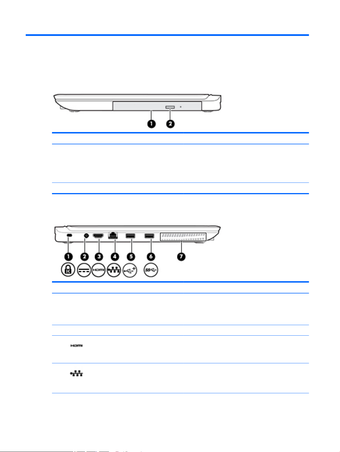
Right side (select products only)
Component Description
(1) Optical drive (select products only) Depending on your computer, reads an optical disc or reads and
writes to an optical disc.
NOTE: For disc compatibility information, type help in the
taskbar search box, select Help and Support, and then type
disc compatibility in the search box.
(2) Optical drive eject button (select products only) Releases the optical drive disc tray.
Left side
Component Description
(1) Security cable slot Attaches an optional security cable to the computer.
(2) Power connector Connects an AC adapter.
(3) HDMI port Connects an optional video or audio device, such as a high-
(4) RJ-45 (network) jack/status lights Connects a network cable.
2 Chapter 2 External component identication
NOTE: The security cable is designed to act as a deterrent, but
it may not prevent the computer from being mishandled or
stolen.
denition television, any compatible digital or audio component,
or a high-speed High-Denition Multimedia Interface (HDMI)
device.
●
White: The network is connected.
●
Amber: Activity is occurring on the network.
Page 11
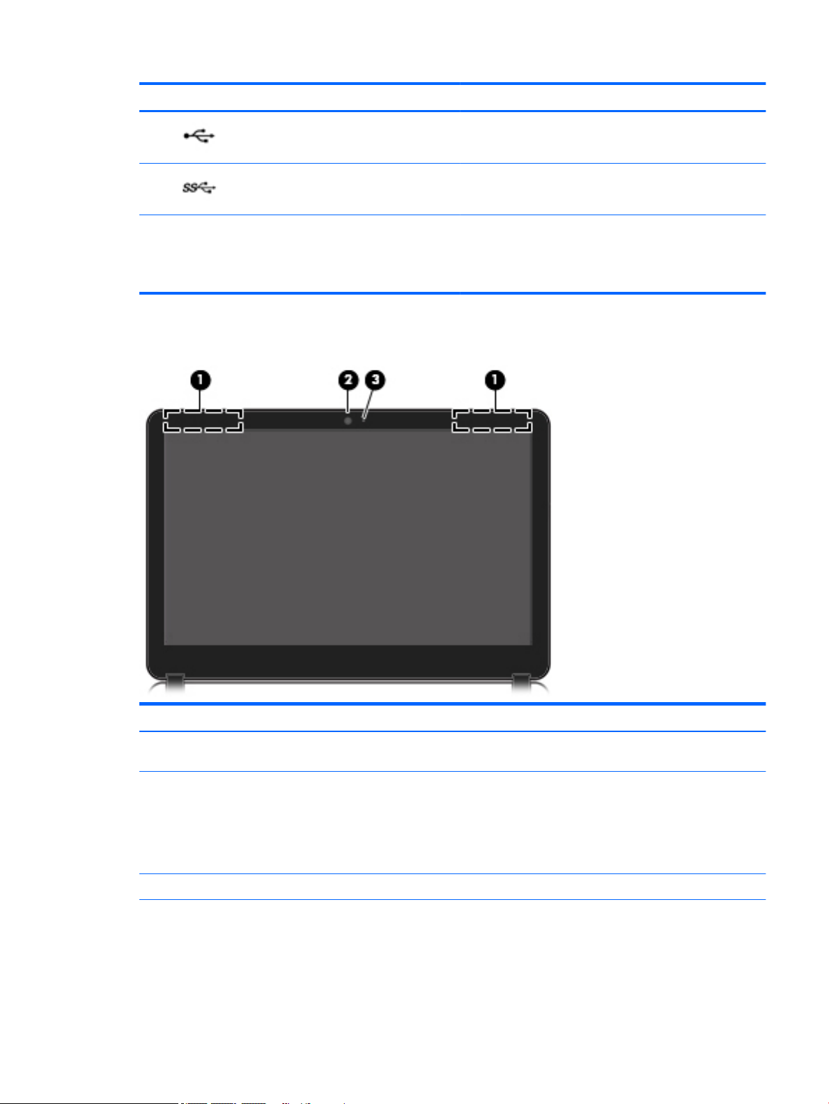
Display
Component Description
(5) USB 2.0 port Connects an optional USB device, such as a keyboard, mouse,
external drive, printer, scanner or USB hub.
(6) USB 3.0 port Connects an optional USB device, such as a keyboard, mouse,
external drive, printer, scanner or USB hub.
(7) Vent Enables airow to cool internal components.
NOTE: The computer fan starts up automatically to cool
internal components and prevent overheating. It is normal for
the internal fan to cycle on and o during routine operation.
Component Description
(1) WLAN antennas (2)* Send and receive wireless signals to communicate with wireless local
area networks (WLANs).
(2) Webcam Records video and captures photographs. Some products allow you
to video conference and chat online using streaming video.
To use a webcam (integrated camera):
▲
Type camera in the taskbar search box, and then select
Camera.
(3) Webcam light On: The webcam is in use.
*The antennas are not visible from the outside of the computer. For optimal transmission, keep the areas immediately around the
antenna free from obstructions.
For wireless regulatory notices, see the section of the Regulatory, Safety, and Environmental Notices that applies to your country or
region.
To access this guide:
Display 3
Page 12
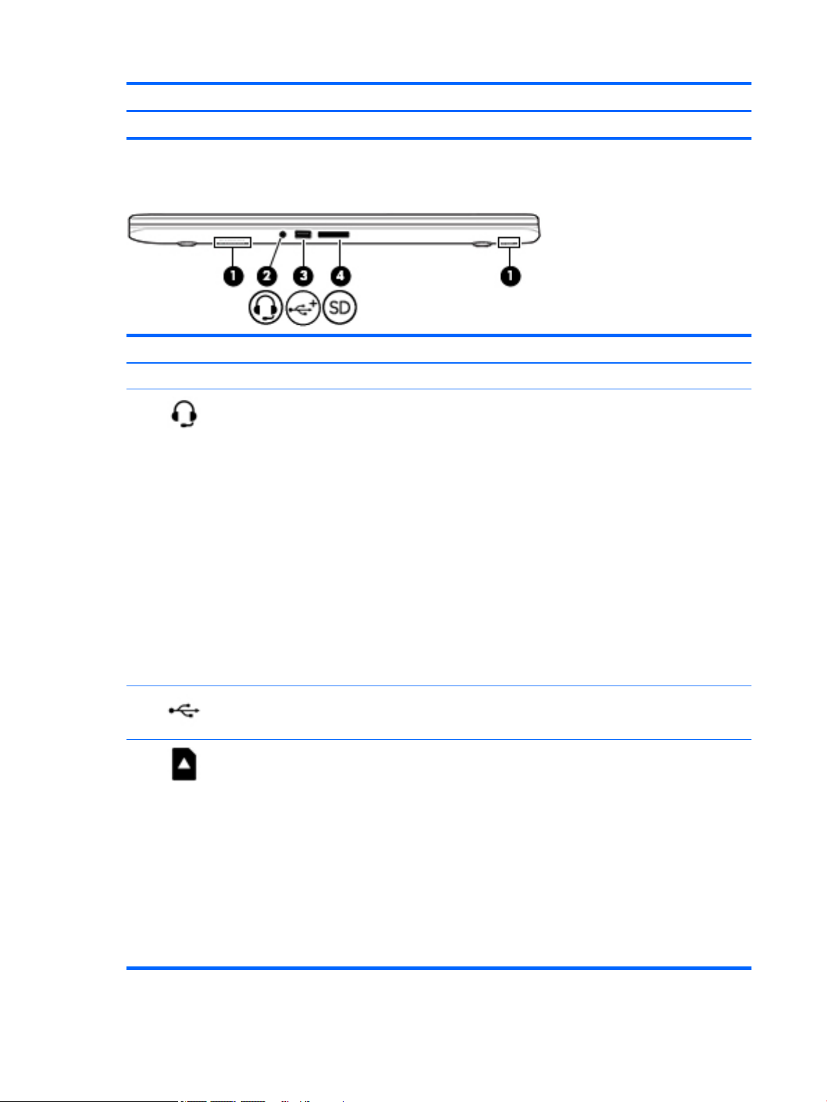
Front
Component Description
▲
Select the Start button, select All apps, select HP Help and Support, and then select HP Documentation.
Component Description
(1) Speakers (2) Produce sound.
(2) Audio-out (headphone)/Audio-in
(microphone) combo jack
(3) USB 2.0 port Connects an optional USB device, such as a
(4) Memory card reader Reads optional memory cards that enable
Connects optional powered stereo speakers,
headphones, earbuds, a headset, or a
television audio cable. Also connects an
optional headset microphone. This jack does
not support optional standalone
microphones.
WARNING! To reduce the risk of personal
injury, adjust the volume before putting on
headphones, earbuds, or a headset. For
additional safety information, refer to the
Regulatory, Safety, and Environmental
Notices.
To access this guide:
▲
Select the Start button, select All
apps, select HP Help and Support, and
then select HP Documentation.
NOTE: When a device is connected to the
jack, the computer speakers are disabled.
keyboard, mouse, external drive, printer,
scanner or USB hub.
you to store, manage, share, or access
information.
To insert a card:
1. Hold the card label-side up, with
connectors facing the computer.
4 Chapter 2 External component identication
2. Insert the card into the memory card
reader, and then press in on the card
until it is rmly seated.
To remove a card:
▲
Press in on the card, and then remove
it from the memory card reader.
Page 13
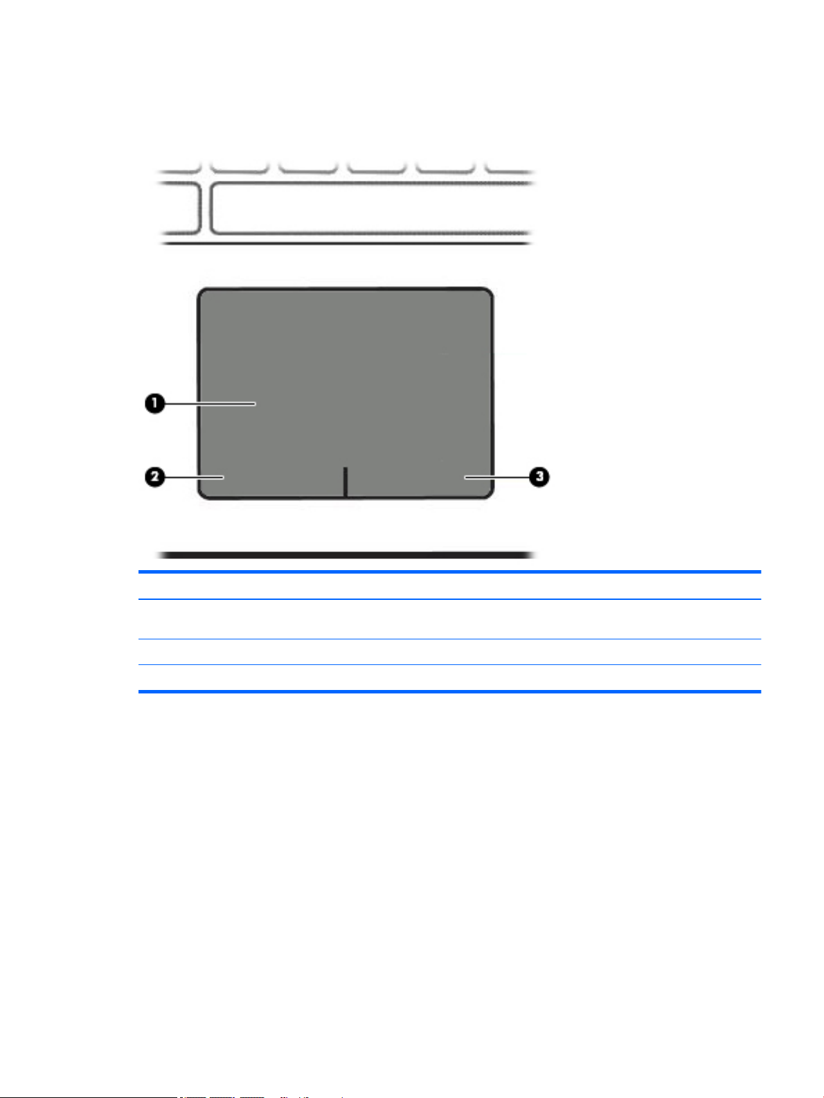
Top
TouchPad
Component Description
(1) TouchPad zone Reads your nger gestures to move the pointer or activate items
(2) Left TouchPad button Functions like the left button on an external mouse.
(3) Right TouchPad button Functions like the right button on an external mouse.
on the screen.
Top 5
Page 14
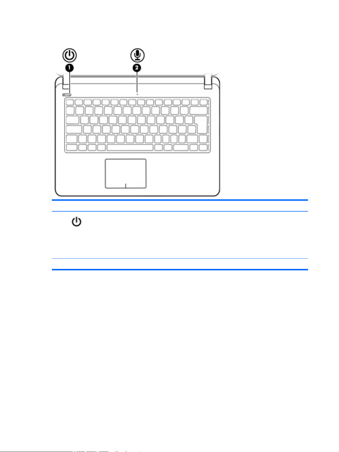
Lights
Component Description
(1) Power light
(2) Internal microphone Records sound.
●
On: The computer is on.
●
Blinking: The computer is in the Sleep state, a powersaving state. The computer shuts o power to the display
and other unneeded components.
●
O: The computer is o or in Hibernation. Hibernation is a
power-saving state that uses the least amount of power.
6 Chapter 2 External component identication
Page 15
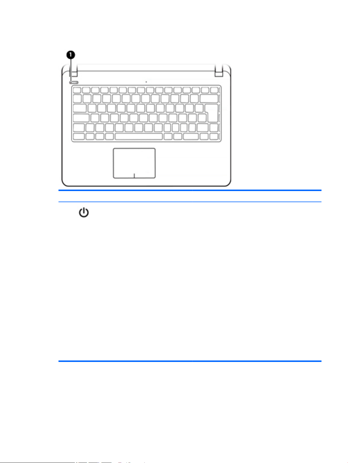
Buttons
Component Description
(1) Power button
●
When the computer is o, press the button to turn on the
computer.
●
When the computer is on, press the button briey to
initiate Sleep.
●
When the computer is in the Sleep state, press the button
briey to exit Sleep.
●
When the computer is in Hibernation, press the button
briey to exit Hibernation.
CAUTION: Pressing and holding down the power button results
in the loss of unsaved information.
If the computer has stopped responding and shutdown
procedures are ineective, press and hold the power button
down for at least 5 seconds to turn o the computer.
To learn more about your power settings, see your power
options.
▲
Type power in the taskbar search box, and then select
Power and sleep settings.
‒ or –
Right-click the Start button, and then select Power
Options.
Top 7
Page 16
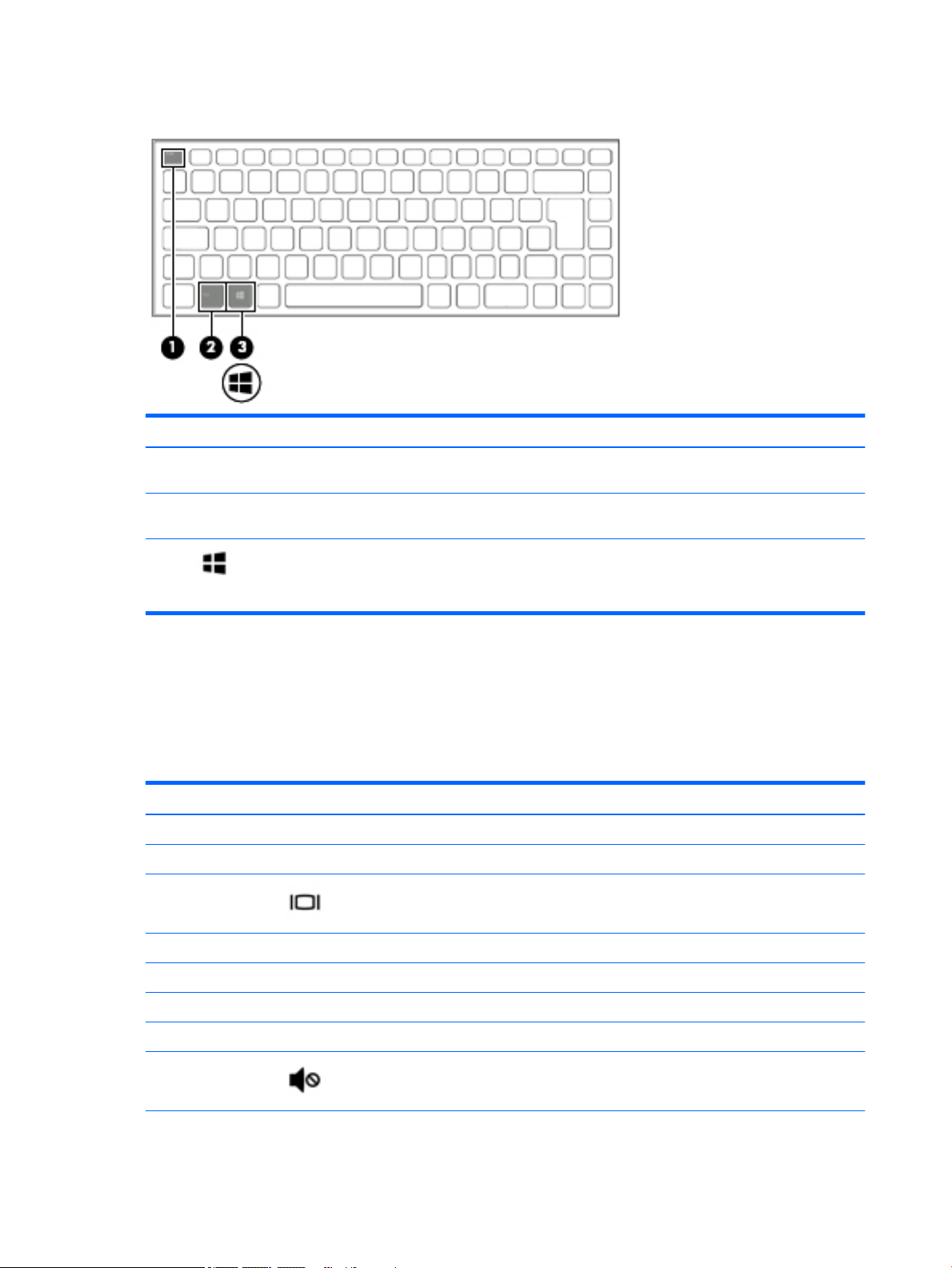
Keys
Component Description
(1) esc key Executes frequently used system functions when pressed in
combination with the fn key.
(2) fn key Executes frequently used system functions when pressed in
combination with the esc key, action keys, or the spacebar.
(3) Windows key Opens the Start menu.
NOTE: Pressing the Windows key again will close the Start
menu.
Using the action keys
●
An action key performs an assigned function.
●
The icon on each action key illustrates the function for that key.
●
To use an action key, press and hold the key.
Function key Icon Description
f1 Suspend
f2 Power saving
f3 Display switch
f4 Radio on/o
f5 On-screen display
f6 TouchPad on/o
f7 Webcam on/o
f8 Mutes or restores speaker sound.
8 Chapter 2 External component identication
Page 17
Function key Icon Description
f9 Decreases speaker volume incrementally while you hold down the key.
f10 Increases speaker volume incrementally while you hold down the key.
f11 Decreases the screen brightness incrementally as long as you hold down the key.
f12 Increases the screen brightness incrementally as long as you hold down the key.
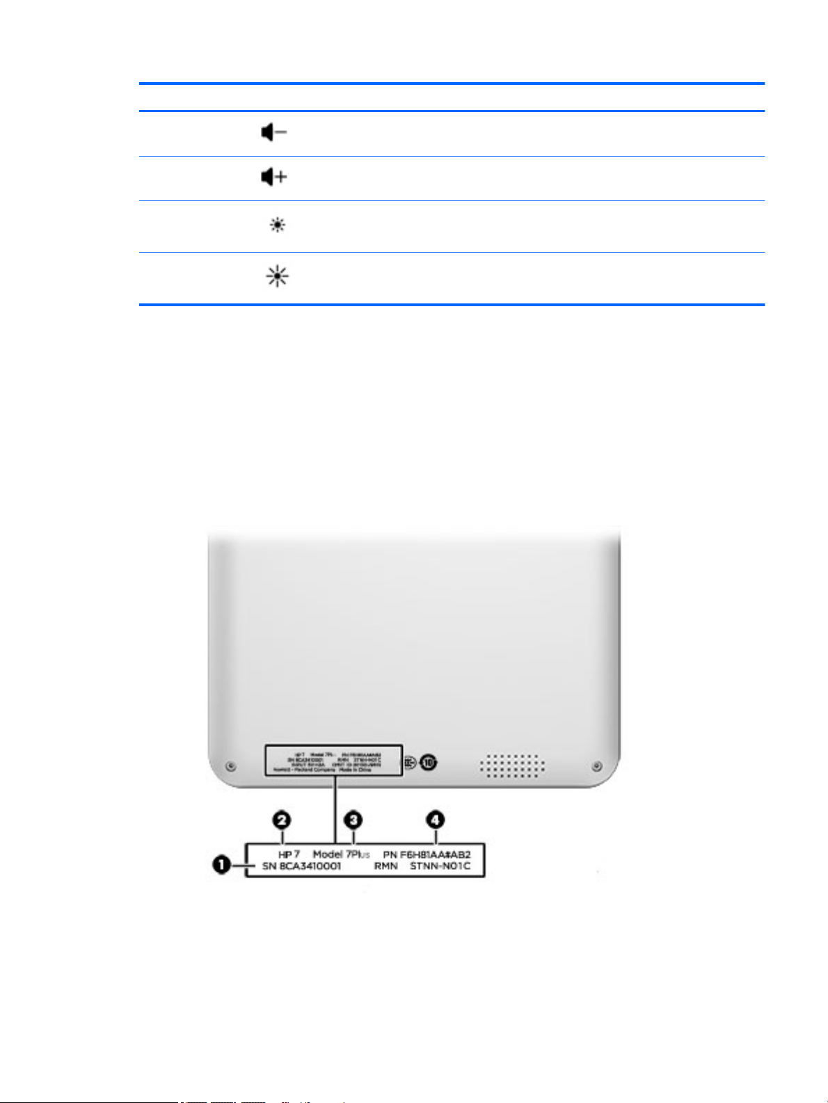
Locating system information
Important system information is located on the back of the computer. You may need the information when
travelling internationally or when you contact support:
(1): Serial number
(2): Product number
(3): Model number
(4): Warranty period
Locating system information 9
Page 18

3 Illustrated parts catalog
Computer major components
NOTE: HP continually improves and changes product parts. For complete and current information on
supported parts for your computer, go to http://partsurfer.hp.com, select your country or region, and then
follow the on-screen instructions.
NOTE: Details about your computer, including model, serial number, product key, and length of warranty,
are on the service tag at the bottom of your computer. See Locating system information on page 9 for details.
10 Chapter 3 Illustrated parts catalog
Page 19
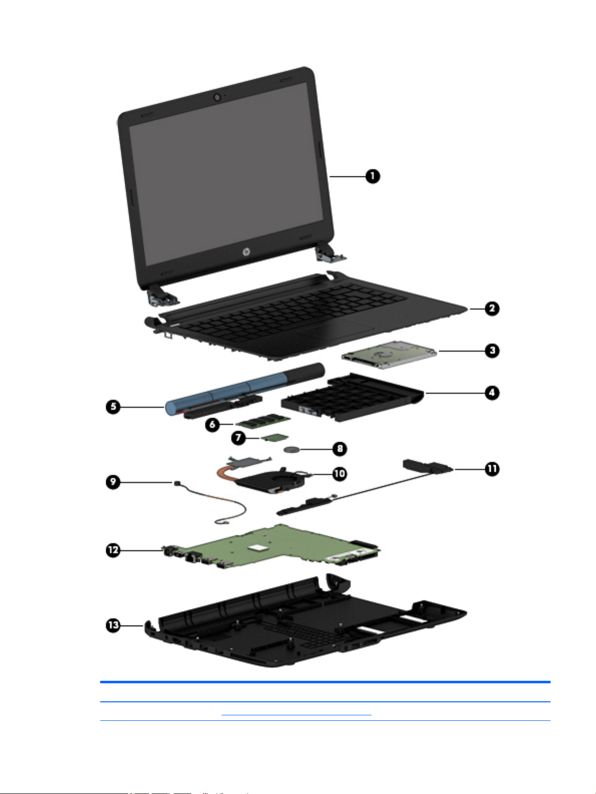
Item Component Spare part number
(1) Display assembly (see Display assembly subcomponents on page 13)
Computer major components 11
Page 20

Item Component Spare part number
(2) Top cover (includes keyboard and TouchPad) 854457-001
(3) Hard drive (see Hard drive on page 23) 683839-855
(4) Optical drive dummy (see Optical drive dummy on page 22) 854470-001
(5) Battery (see Battery on page 22) 854472-001
(6) Memory (see Memory on page 25) 691799-855
(7) WLAN module (see WLAN module on page 28) 792505-855
(8) RTC battery 855483-001
(9) Webcam (see Webcam on page 45) 854509-001
(10) Fan (see Heat sink and fan on page 30) 854468-001
Heat sink (see Heat sink and fan on page 30) 854469-001
(11) Speaker (see Speakers on page 32) 854475-001
(12) System board (see System board on page 36) 854479-001
(13) Base enclosure 854473-001
12 Chapter 3 Illustrated parts catalog
Page 21
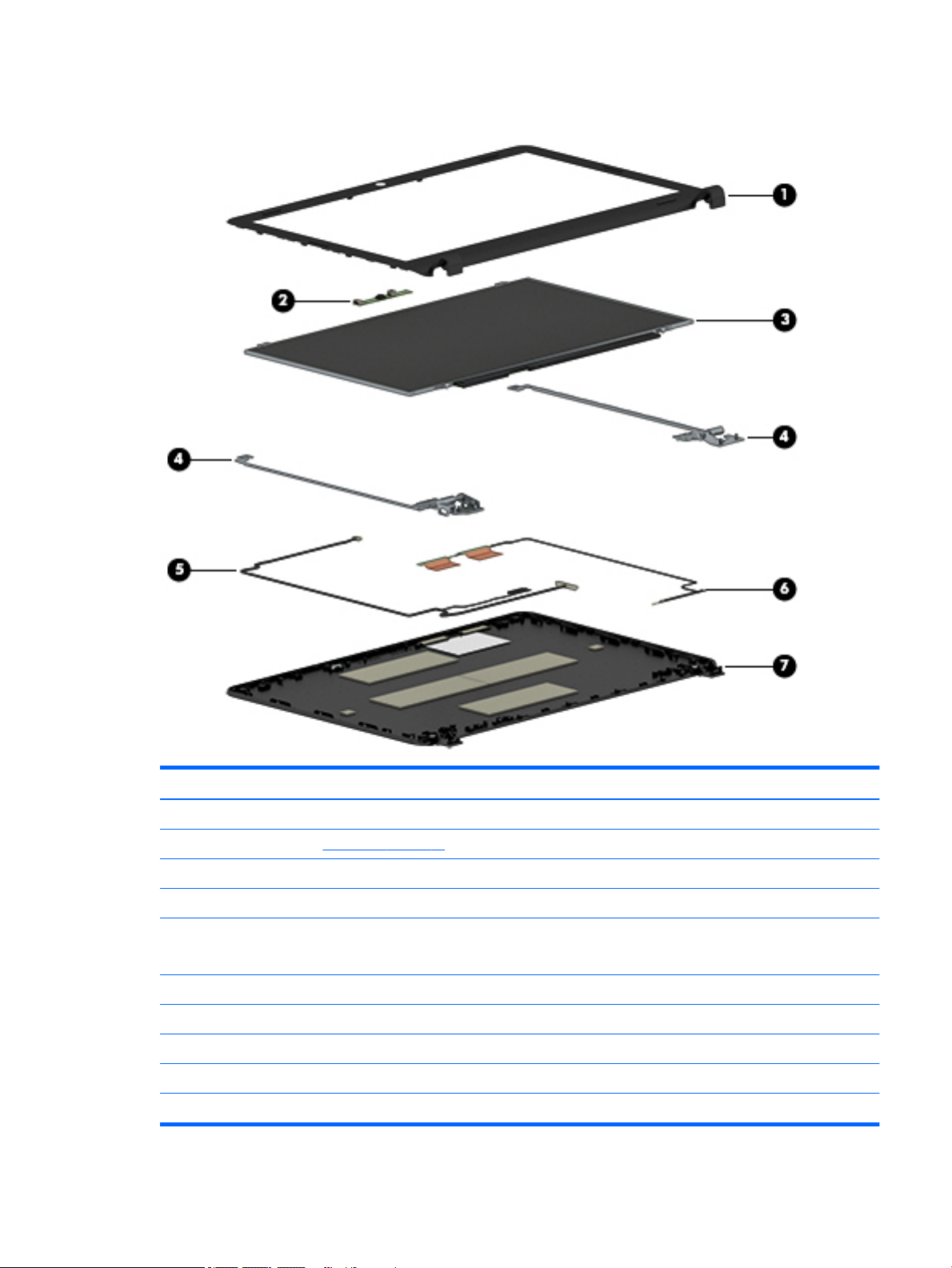
Display assembly subcomponents
Item Component Spare part number
(1) Display bezel 854447-001
(2) Microphone (see Microphone on page 34) 854474-001
(3) Panel 854448-001
(4) Hinge kit 854508-001
(5) WLAN antennas 854450-001
854451-001
(6) WLAN cable 792505-855
(7) Back cover 854507-001
Not shown:
Display cable 854449-001
Touch panel cable (select products only) 854477-001
Display assembly subcomponents 13
Page 22

Miscellaneous parts
Component Spare part number
AC adapter 741553-851
DC connector 854443-001
Middle frame 854476-001
Power cord 438722-004
Screw kit 854511-001
RTC battery 855483-001
14 Chapter 3 Illustrated parts catalog
Page 23

4 Removal and replacement procedures
preliminary requirements
Tools required
You will need the following tools to complete the removal and replacement procedures:
●
Flat-bladed screwdriver
●
Magnetic screwdriver
●
Phillips P0 and P1 screwdrivers
Service considerations
The following sections include some of the considerations that you must keep in mind during disassembly
and assembly procedures.
NOTE: As you remove each subassembly from the computer, place the subassembly (and all accompanying
screws) away from the work area to prevent damage.
Plastic parts
CAUTION: Using excessive force during disassembly and reassembly can damage plastic parts. Use care
when handling the plastic
Tools required 15
Page 24

Cables and connectors
CAUTION: When servicing the computer, be sure that cables are placed in their proper locations during the
reassembly process. Improper cable placement can damage the computer.
Cables must be handled with extreme care to avoid damage. Apply only the tension required to unseat or seat
the cables during removal and insertion. Handle cables by the connector whenever possible. In all cases, avoid
bending, twisting, or tearing cables. Be sure that cables are routed in such a way that they cannot be caught
or snagged by parts being removed or replaced. Handle ex cables with extreme care; these cables tear
easily.
Drive handling
CAUTION: Drives are fragile components that must be handled with care. To prevent damage to the
computer, damage to a drive, or loss of information, observe these precautions:
Before removing or inserting a hard drive, shut down the computer. If you are unsure whether the computer is
o or in Hibernation, turn the computer on, and then shut it down through the operating system.
Before handling a drive, be sure that you are discharged of static electricity. While handling a drive, avoid
touching the connector.
Before removing an optical drive, be sure that a disc is not in the drive and be sure that the optical drive tray is
closed.
Handle drives on surfaces covered with at least one inch of shock-proof foam.
Avoid dropping drives from any height onto any surface.
After removing a hard drive or an optical drive, place it in a static-proof bag.
Avoid exposing an internal hard drive to products that have magnetic elds, such as monitors or speakers.
Avoid exposing a drive to temperature extremes or liquids.
If a drive must be mailed, place the drive in a bubble pack mailer or other suitable form of protective
packaging and label the package “FRAGILE.”
16 Chapter 4 Removal and replacement procedures preliminary requirements
Page 25

Grounding guidelines
Electrostatic discharge damage
Electronic components are sensitive to electrostatic discharge (ESD). Circuitry design and structure determine
the degree of sensitivity. Networks built into many integrated circuits provide some protection, but in many
cases, ESD contains enough power to alter device parameters or melt silicon junctions.
A discharge of static electricity from a nger or other conductor can destroy static-sensitive devices or
microcircuitry. Even if the spark is neither felt nor heard, damage may have occurred.
An electronic device exposed to ESD may not be aected at all and can work perfectly throughout a normal
cycle. Or the device may function normally for a while, then degrade in the internal layers, reducing its life
expectancy.
CAUTION: To prevent damage to the computer when you are removing or installing internal components,
observe these precautions:
Keep components in their electrostatic-safe containers until you are ready to install them.
Before touching an electronic component, discharge static electricity by using the guidelines described in this
section.
Avoid touching pins, leads, and circuitry. Handle electronic components as little as possible.
If you remove a component, place it in an electrostatic-safe container.
The following table shows how humidity aects the electrostatic voltage levels generated by dierent
activities.
CAUTION: A product can be degraded by as little as 700 V.
Typical electrostatic voltage levels
Relative humidity
Event 10% 40% 55%
Walking across carpet 35,000 V 15,000 V 7,500 V
Walking across vinyl oor 12,000 V 5,000 V 3,000 V
Motions of bench worker 6,000 V 800 V 400 V
Removing DIPS from plastic tube 2,000 V 700 V 400 V
Removing DIPS from vinyl tray 11,500 V 4,000 V 2,000 V
Removing DIPS from plastic foam 14,500 V 5,000 V 3,500 V
Removing bubble pack from PCB 26,500 V 20,000 V 7,000 V
Packing PCBs in foam-lined box 21,000 V 11,000 V 5,000 V
Grounding guidelines 17
Page 26

Packaging and transporting guidelines
Follow these grounding guidelines when packaging and transporting equipment:
●
To avoid hand contact, transport products in static-safe tubes, bags, or boxes.
●
Protect ESD-sensitive parts and assemblies with conductive or approved containers or packaging.
●
Keep ESD-sensitive parts in their containers until the parts arrive at static-free workstations.
●
Place items on a grounded surface before removing items from their containers.
●
Always be properly grounded when touching a component or assembly.
●
Store reusable ESD-sensitive parts from assemblies in protective packaging or nonconductive foam.
●
Use transporters and conveyors made of antistatic belts and roller bushings. Be sure that mechanized
equipment used for moving materials is wired to ground and that proper materials are selected to avoid
static charging. When grounding is not possible, use an ionizer to dissipate electric charges.
Workstation guidelines
Follow these grounding workstation guidelines:
●
Cover the workstation with approved static-shielding material.
●
Use a wrist strap connected to a properly grounded work surface and use properly grounded tools and
equipment.
●
Use conductive eld service tools, such as cutters, screwdrivers, and vacuums.
●
When xtures must directly contact dissipative surfaces, use xtures made only of static safe materials.
●
Keep the work area free of nonconductive materials, such as ordinary plastic assembly aids and plastic
foam.
●
Handle ESD-sensitive components, parts, and assemblies by the case or PCM laminate. Handle these
items only at static-free workstations.
●
Avoid contact with pins, leads, or circuitry.
●
Turn o power and input signals before inserting or removing connectors or test equipment.
18 Chapter 4 Removal and replacement procedures preliminary requirements
Page 27

Equipment guidelines
Grounding equipment must include either a wrist strap or a foot strap at a grounded workstation.
●
When seated, wear a wrist strap connected to a grounded system. Wrist straps are exible straps with a
minimum of one megohm ±10% resistance in the ground cords. To provide proper ground, wear a strap
snugly against the skin at all times. On grounded mats with banana-plug connectors, use alligator clips
to connect a wrist strap.
●
When standing, use foot straps and a grounded oor mat. Foot straps (heel, toe, or boot straps) can be
used at standing workstations and are compatible with most types of shoes or boots. On conductive
oors or dissipative oor mats, use foot straps on both feet with a minimum of one megohm resistance
between the operator and ground. To be eective, the conductive equipment must be worn in contact
with the skin.
The following grounding equipment is recommended to prevent electrostatic damage:
●
Antistatic tape
●
Antistatic smocks, aprons, and sleeve protectors
●
Conductive bins and other assembly or soldering aids
●
Nonconductive foam
●
Conductive tabletop workstations with ground cords of one megohm resistance
●
Static-dissipative tables or oor mats with hard ties to the ground
●
Field service kits
●
Static awareness labels
●
Material-handling packages
●
Nonconductive plastic bags, tubes, or boxes
●
Metal tote boxes
●
Electrostatic voltage levels and protective materials
The following table lists the shielding protection provided by antistatic bags and oor mats.
Material Use Voltage protection level
Antistatic plastics Bags 1,500 V
Carbon-loaded plastic Floor mats 7,500 V
Metallized laminate Floor mats 5,000 V
Grounding guidelines 19
Page 28

5 Removal and replacement procedures for
authorized service provider parts
CAUTION: Components described in this chapter should be accessed only by an authorized service provider.
Accessing these parts can damage the computer or void the warranty.
CAUTION: This computer does not have user-replaceable parts. Only HP authorized service providers should
perform the removal and replacement procedures described here. Accessing the internal part could damage
the computer or void the warranty.
Component replacement procedures
NOTE: Details about your computer, including model, serial number, product key, and length of warranty,
are on the service tag at the bottom of your computer. See Locating system information on page 9 for details.
NOTE: HP continually improves and changes product parts. For complete and current information on
supported parts for your computer, go to http://partsurfer.hp.com, select your country or region, and then
follow the on-screen instructions.
There are as many as xx screws that must be removed, replaced, and/or loosened when servicing the parts
described in this chapter. Make special note of each screw size and location during removal and replacement.
Base enclosure
Description Spare part number
Base enclosure 854473-001
Before disassembling the computer, follow these steps:
1. Turn o the computer. If you are unsure whether the computer is o or in Hibernation, turn
the computer on, and then shut it down through the operating system.
2. Disconnect the power from the computer by unplugging the power cord from the computer.
3. Disconnect all external devices from the computer.
Remove the base enclosure:
1. Position the computer upside down on a at surface.
2. Remove 13 screws (1).
3. Slide a nylon ake tool around the edge of the base enclosure (2) to loosen it, taking care not to damage
the internal clips.
20 Chapter 5 Removal and replacement procedures for authorized service provider parts
Page 29

4. Press lightly on the base enclosure with both hands to release the headphone jack before removing the
base enclosure (3).
Component replacement procedures 21
Page 30

Battery
Description Spare part number
Battery LI-ION, 23.76 Wh, 00, N/A 854472-001
Remove the battery:
WARNING! To reduce potential safety issues, use only the user-replaceable battery provided with the
computer, a replacement battery provided by HP, or a compatible battery purchased from HP.
CAUTION: Removing a user-replaceable battery that is the sole power source for the computer can cause
loss of information. To prevent loss of information, save your work or shut down the computer through
Windows before removing the battery.
1. Position the computer upside down on a at surface.
2. Carefully remove the battery to avoid damaging the connection.
To insert the battery, reverse the removal procedures.
Optical drive dummy
Description
Optical drive dummy 854470-001
Optical drive bezel 854471-001
IMPORTANT: Make special note of each screw and screw lock size and location during removal
and replacement.
22 Chapter 5 Removal and replacement procedures for authorized service provider parts
Spare part number
Page 31

Before removing the optical drive dummy, follow these steps:
1. Shut down the computer.
2. Disconnect all external devices connected to the computer.
3. Disconnect the power from the computer by rst unplugging the power cord from the AC outlet and then
unplugging the AC adapter from the computer.
4. Remove the base enclosure (see Base enclosure on page 20), and then remove the following
components:
▲
Battery (see Battery on page 22).
Remove the optical drive dummy:
▲
Remove 1 screw (1), and then remove the optical drive dummy (2).
Reverse this procedure to install the optical drive dummy.
Hard drive
Description Spare part number
Hard drive, SATA 500 GB 5400 RPM 7MM 683839-855
IMPORTANT: Make special note of each screw and screw lock size and location during removal
and replacement.
Before removing the hard drive, follow these steps:
1. Shut down the computer.
2. Disconnect all external devices connected to the computer.
Component replacement procedures 23
Page 32

3. Disconnect the power from the computer by rst unplugging the power cord from the AC outlet and then
unplugging the AC adapter from the computer.
4. Remove the base enclosure (see Base enclosure on page 20), and then remove the following
components:
a. Battery (see Battery on page 22).
b. Optical drive dummy (see Optical drive dummy on page 22).
Remove the hard drive:
▲
Gently pull the hard drive horizontally (1), and then remove it (2).
Reverse this procedure to install the hard drive.
24 Chapter 5 Removal and replacement procedures for authorized service provider parts
Page 33

Memory
Description Spare part number
Memory—SODIMM 4GB PC3L 12800 (maximum 8 GB) 691799-855
IMPORTANT: Make special note of each screw and screw lock size and location during removal
and replacement.
Before removing the memory, follow these steps:
1. Shut down the computer.
2. Disconnect all external devices connected to the computer.
3. Disconnect the power from the computer by rst unplugging the power cord from the AC outlet and then
unplugging the AC adapter from the computer.
4. Remove the base enclosure (see Base enclosure on page 20), and then remove the following
components:
a. Battery (see Battery on page 22).
b. Optical drive dummy (see Optical drive dummy on page 22).
c. Hard drive (see Hard drive on page 23).
If you are replacing a memory module, remove the existing memory module:
1. Lift the clear lm covering the memory module.
2. Pull away the retention clips (1) on each side of the memory module.
The memory module tilts up.
Component replacement procedures 25
Page 34

3. Grasp the edge of the memory module (2), and then gently pull the memory module out of the memory
module slot.
CAUTION: To prevent damage to the memory module, hold the memory module by the edges only. Do
not touch the components on the memory module.
To protect a memory module after removal, place it in an electrostatic-safe container.
To install a memory module:
CAUTION: To prevent damage to the memory module, hold the memory module by the edges only. Do not
touch the components on the memory module.
1. Align the notched edge (1) of the memory module with the tab in the memory module slot.
26 Chapter 5 Removal and replacement procedures for authorized service provider parts
Page 35

2. With the memory module at a 45-degree angle from the surface of the memory module compartment
(2), press the module into the memory module slot until it is seated.
3. Gently press the memory module down (3), applying pressure to both the left and right edges of the
memory module, until the retention clips snap into place.
CAUTION: To prevent damage to the memory module, be sure that you do not bend the memory
module.
Component replacement procedures 27
Page 36

WLAN module
Description Spare part number
WLAN RT 802.11 b/g/n +Bluetooth 4.0 1x1 SANJI 792505-855
IMPORTANT: Make special note of each screw and screw lock size and location during removal
and replacement.
Before removing the WLAN module, follow these steps:
1. Shut down the computer.
2. Disconnect all external devices connected to the computer.
3. Disconnect the power from the computer by rst unplugging the power cord from the AC outlet and then
unplugging the AC adapter from the computer.
4. Remove the base enclosure (see Base enclosure on page 20), and then remove the following
components:
a. Battery (see Battery on page 22).
b. Optical drive dummy (see Optical drive dummy on page 22).
c. Hard drive (see Hard drive on page 23).
d. Memory (see Memory on page 25).
Remove the WLAN module:
1. Carefully disconnect 2 antenna cables (1).
28 Chapter 5 Removal and replacement procedures for authorized service provider parts
Page 37

2. Remove 1 Phillips screw (2), and then remove the WLAN module (3).
Reverse this procedure to install the WLAN module.
Component replacement procedures 29
Page 38

Heat sink and fan
Description Spare part number
Fan 854468-001
Heat sink 854469-001
IMPORTANT: Make special note of each screw and screw lock size and location during removal
and replacement.
Before removing the heat sink and the fan, follow these steps:
1. Shut down the computer.
2. Disconnect all external devices connected to the computer.
3. Disconnect the power from the computer by rst unplugging the power cord from the AC outlet and then
unplugging the AC adapter from the computer.
4. Remove the base enclosure (see Base enclosure on page 20), and then remove the following
components:
a. Battery (see Battery on page 22).
b. Optical drive dummy (see Optical drive dummy on page 22).
c. Hard drive (see Hard drive on page 23).
d. Memory (see Memory on page 25).
e. WLAN module (see WLAN module on page 28).
Remove the heat sink and the fan:
1. Disconnect the heat sink connector from the system board (1), and then loosen the cables from the
routing channels.
2. Remove 3 screws from the heat sink(2), and then loosen 3 captive screws from the fan (3).
30 Chapter 5 Removal and replacement procedures for authorized service provider parts
Page 39

3. Lift to remove the heat sink and fan assembly(4).
Reverse this procedure to install the heat sink and the fan.
Component replacement procedures 31
Page 40

Speakers
NOTE: The speaker spare part kit includes the cable.
IMPORTANT: Make special note of each screw and screw lock size and location during removal
and replacement.
Before removing the speaker, follow these steps:
1. Shut down the computer.
2. Disconnect all external devices connected to the computer.
3. Disconnect the power from the computer by rst unplugging the power cord from the AC outlet and then
4. Remove the base enclosure (see Base enclosure on page 20), and then remove the following
Description Spare part number
Speaker Kit 854475-001
unplugging the AC adapter from the computer.
components:
a. Battery (see Battery on page 22).
b. Optical drive dummy (see Optical drive dummy on page 22).
c. Hard drive (see Hard drive on page 23).
d. Memory (see Memory on page 25).
e. WLAN module (see WLAN module on page 28).
f. Heat sink and fan (see Heat sink and fan on page 30).
Remove the speakers:
1. Disconnect the connector from the system board (1).
2. Release the speaker cable from the routing channels (2).
32 Chapter 5 Removal and replacement procedures for authorized service provider parts
Page 41

3. Lift the left speaker and the right speaker (3) to remove them.
Reverse this procedure to install the speakers.
Component replacement procedures 33
Page 42

Microphone
Description Spare part number
Microphone 854474-001
IMPORTANT: Make special note of each screw and screw lock size and location during removal
and replacement.
Before removing the microphone, follow these steps:
1. Shut down the computer.
2. Disconnect all external devices connected to the computer.
3. Disconnect the power from the computer by rst unplugging the power cord from the AC outlet and then
4. Remove the base enclosure (see Base enclosure on page 20), and then remove the following
unplugging the AC adapter from the computer.
components:
a. Battery (see Battery on page 22).
b. Optical drive dummy (see Optical drive dummy on page 22).
c. Hard drive (see Hard drive on page 23).
d. Memory (see Memory on page 25).
e. WLAN module (see WLAN module on page 28).
f. Heat sink and fan (see Heat sink and fan on page 30).
g. Speakers (see Speakers on page 32).
Remove the microphone:
1. Remove 4 strips of tape from the microphone cable, and then disconnect the microphone connector
from the system board (1).
34 Chapter 5 Removal and replacement procedures for authorized service provider parts
Page 43

2. Pull the microphone up carefully to avoid breaking the cable (2), and then remove it (3).
Reverse this procedure to install the microphone.
Component replacement procedures 35
Page 44

System board
Description Spare part number
System board
Intel system board i3-5005U 854479-001
Intel system board Celeron 3215U 854480-001
IMPORTANT: Make special note of each screw and screw lock size and location during removal
and replacement.
Before removing the system board, follow these steps:
1. Shut down the computer.
2. Disconnect all external devices connected to the computer.
3. Disconnect the power from the computer by rst unplugging the power cord from the AC outlet and then
unplugging the AC adapter from the computer.
4. Remove the base enclosure (see Base enclosure on page 20), and then remove the following
components:
a. Battery (see Battery on page 22).
b. Optical drive dummy (see Optical drive dummy on page 22).
c. Hard drive (see Hard drive on page 23).
d. Memory (see Memory on page 25).
e. WLAN module (see WLAN module on page 28).
f. Heat sink and fan (see Heat sink and fan on page 30).
g. Speakers (see Speakers on page 32).
h. Microphone (see Microphone on page 34).
Remove the system board:
1. Open the keyboard cable zero-insertion force (ZIF) connector (1), and then release it from the system
board (2).
36 Chapter 5 Removal and replacement procedures for authorized service provider parts
Page 45

2. Open the display cable zero-insertion force (ZIF) connector (1), and then release it from the system
board (2).
Component replacement procedures 37
Page 46

3. Open the TouchPad cable zero-insertion force (ZIF) connector (1), and then disconnect if from the
system board (2).
4. Remove 2 Phillips screws (1).
5. Lift the system board (2), and then remove it (3).
Reverse this procedure to install the system board.
38 Chapter 5 Removal and replacement procedures for authorized service provider parts
Page 47

WLAN cable
Description Spare part number
WLAN cable 792505-855
IMPORTANT: Make special note of each screw and screw lock size and location during removal
and replacement.
Before removing the WLAN cable, follow these steps:
1. Shut down the computer.
2. Disconnect all external devices connected to the computer.
3. Disconnect the power from the computer by rst unplugging the power cord from the AC outlet and then
4. Remove the base enclosure (see Base enclosure on page 20), and then remove the following
unplugging the AC adapter from the computer.
components:
a. Battery (see Battery on page 22).
b. Optical drive dummy (see Optical drive dummy on page 22).
c. Hard drive (see Hard drive on page 23).
d. Memory (see Memory on page 25).
e. WLAN module (see WLAN module on page 28).
f. Heat sink and fan (see Heat sink and fan on page 30).
g. Speakers (see Speakers on page 32).
h. Microphone (see Microphone on page 34).
i. System board(see System board on page 36).
Remove the WLAN cable:
▲
Disconnect the WLAN antenna from the WLAN module(1), release the WLAN cable from the tape
securing it (2), and then lift the cable to remove it (3).
Component replacement procedures 39
Page 48

Reverse this procedure to install the WLAN cable.
40 Chapter 5 Removal and replacement procedures for authorized service provider parts
Page 49

Display assembly
Description Spare part number
Bezel 854447-001
Panel 854448-001
Display cable 854449-001
Touch panel cable (select products only) 854477-001
Hinge kit (includes left and right hinges 854508-001
WLAN antenna, 670 mm 854450-001
WLAN antenna, 720 mm 854451-001
IMPORTANT: Make special note of each screw and screw lock size and location during removal
and replacement.
Before removing the display assembly, follow these steps:
1. Shut down the computer.
2. Disconnect all external devices connected to the computer.
3. Disconnect the power from the computer by rst unplugging the power cord from the AC outlet and then
unplugging the AC adapter from the computer.
4. Remove the base enclosure (see Base enclosure on page 20), and then remove the following
components:
a. Battery (see Battery on page 22).
b. Optical drive dummy (see Optical drive dummy on page 22).
c. Hard drive (see Hard drive on page 23).
d. Memory (see Memory on page 25).
e. WLAN module (see WLAN module on page 28).
f. Heat sink and fan (see Heat sink and fan on page 30).
g. Speakers (see Speakers on page 32).
h. Microphone (see Microphone on page 34).
i. System board(see System board on page 36).
j. WLAN cable (see WLAN cable on page 39).
Remove the display assembly:
1. Remove 2 screws from the right hinge and 3 screws from the left hinge (1), and then remove the display
assembly (2).
Component replacement procedures 41
Page 50

2. Remove 4 screws from the right hinge and 3 screws from the left hinge (1), and then remove the display
assembly (2).
3. Slide a nylon ake tool (1) around the outer edge of the bezel to release the bezel from the screen (2).
42 Chapter 5 Removal and replacement procedures for authorized service provider parts
Page 51

4. Lift the sides of the bezel (3), and then remove it (4).
5. Remove the tape covering the display panel connector (1), and then disconnect it from the display panel
(2).
Component replacement procedures 43
Page 52

6. Remove 4 screws from the display panel (1), and then remove it (2).
7. Remove 1 screw from the top of each hinge bracket (1) and 3 screws from each hinge (2) and then
remove the hinge brackets (3).
Reverse this procedure to install the display assembly.
44 Chapter 5 Removal and replacement procedures for authorized service provider parts
Page 53

Webcam
Description Spare part number
Webcam 854509-001
IMPORTANT: Make special note of each screw and screw lock size and location during removal
and replacement.
Before removing the webcam, follow these steps:
1. Shut down the computer.
2. Disconnect all external devices connected to the computer.
3. Disconnect the power from the computer by rst unplugging the power cord from the AC outlet and then
unplugging the AC adapter from the computer.
4. Remove the base enclosure (see Base enclosure on page 20), and then remove the following
components:
a. Battery (see Battery on page 22).
b. Optical drive dummy (see Optical drive dummy on page 22).
c. Hard drive (see Hard drive on page 23).
d. Memory (see Memory on page 25).
e. WLAN module (see WLAN module on page 28).
f. Heat sink and fan (see Heat sink and fan on page 30).
g. Speakers (see Speakers on page 32).
h. Microphone (see Microphone on page 34).
i. System board(see System board on page 36).
j. WLAN cable (see WLAN cable on page 39).
k. Display assembly (see Display assembly on page 41).
Remove the webcam:
▲
Lift the webcam board (1), disconnect the webcam cable (2), and then use a nylon ake tool to remove
the webcam (3).
Component replacement procedures 45
Page 54

Reverse this procedure to install the webcam.
46 Chapter 5 Removal and replacement procedures for authorized service provider parts
Page 55

6 Using Setup Utility (BIOS)
Setup Utility, or Basic Input/Output System (BIOS), controls communication between all the input and output
devices on the system (such as disk drives, display, keyboard, mouse, and printer). Setup Utility (BIOS)
includes settings for the types of devices installed, the startup sequence of the computer, and the amount of
system and extended memory.
NOTE: To start Setup Utility on convertible computers, your computer must be in notebook mode and you
must use the keyboard attached to your notebook.
Starting Setup Utility (BIOS)
CAUTION: Use extreme care when making changes in Setup Utility (BIOS). Errors can prevent the computer
from operating properly.
▲
Turn on or restart the computer, quickly press esc, and then press f10.
Updating Setup Utility (BIOS)
Updated versions of Setup Utility (BIOS) may be available on the HP website.
Most BIOS updates on the HP website are packaged in compressed les called SoftPaqs.
Some download packages contain a le named Readme.txt, which contains information regarding installing
and troubleshooting the le.
Determining the BIOS version
To decide whether you need to update Setup Utility (BIOS), rst determine the BIOS version on your computer.
To reveal the BIOS version information (also known as ROM date and System BIOS), use one of these options.
●
HP Support Assistant
1. Type support in the taskbar search box, and then select the HP Support Assistant app.
– or –
Click the question mark icon in the taskbar.
2. Select My PC, and then select Specications.
●
Setup Utility (BIOS)
1. Start Setup Utility (BIOS) (see Starting Setup Utility (BIOS) on page 47).
2. Select Main, select System Information, and then make note of the BIOS version.
3. Select Exit, select No, and then follow the on-screen instructions.
To check for later BIOS versions, see Downloading a BIOS update on page 48.
Starting Setup Utility (BIOS) 47
Page 56

Downloading a BIOS update
CAUTION: To reduce the risk of damage to the computer or an unsuccessful installation, download and
install a BIOS update only when the computer is connected to reliable external power using the AC adapter. Do
not download or install a BIOS update while the computer is running on battery power, docked in an optional
docking device, or connected to an optional power source. During the download and installation, follow these
instructions:
●
Do not disconnect power from the computer by unplugging the power cord from the AC outlet.
●
Do not shut down the computer or initiate Sleep.
●
Do not insert, remove, connect, or disconnect any device, cable, or cord.
NOTE: If your computer is connected to a network, consult the network administrator before installing any
software updates, especially system BIOS updates.
1. Type support in the taskbar search box, and then select the HP Support Assistant app.
– or –
Click the question mark icon in the taskbar.
2. Click Updates, and then click Check for updates and messages.
3. Follow the on-screen instructions.
4. At the download area, follow these steps:
a. Identify the most recent BIOS update and compare it to the BIOS version currently installed on your
computer. If the update is more recent than your BIOS version, make a note of the date, name, or
other identier. You may need this information to locate the update later, after it has been
downloaded to your hard drive.
b. Follow the on-screen instructions to download your selection to the hard drive.
Make a note of the path to the location on your hard drive where the BIOS update is downloaded.
You will need to access this path when you are ready to install the update.
BIOS installation procedures vary. Follow any instructions that appear on the screen after the download is
complete. If no instructions appear, follow these steps:
1. Type file in the taskbar search box, and then select File Explorer.
2. Click your hard drive designation. The hard drive designation is typically Local Disk (C:).
3. Using the hard drive path you recorded earlier, open the folder that contains the update.
4. Double-click the le that has an .exe extension (for example, lename.exe).
The BIOS installation begins.
5. Complete the installation by following the on-screen instructions.
NOTE: After a message on the screen reports a successful installation, you can delete the downloaded le
from your hard drive.
48 Chapter 6 Using Setup Utility (BIOS)
Page 57

7 Backing up, restoring, and recovering
This chapter provides information about the following processes. The information in the chapter is standard
procedure for most products.
●
Creating recovery media and backups
●
Restoring and recovering your system
Creating recovery media and backups
The following methods of creating recovery media and backups are available on select products only. Choose
the available method according to your computer model.
●
Use Windows tools to create system restore points and create backups of personal information.
NOTE: If storage is 32 GB or less, Microsoft System Restore is disabled by default.
Creating HP Recovery media (select products only)
If possible, check for the presence of the Recovery partition and the Windows partition. From the Start menu,
select File Explorer, and then select This PC.
●
If your computer does not list the Windows partition and the Recovery partition, you can obtain recovery
media for your system from support. See the Worldwide Telephone Numbers booklet included with the
computer. You can also nd contact information on the HP website. Go to http://www.hp.com/support,
select your country or region, and follow the on-screen instructions.
You can use Windows tools to create system restore points and create backups of personal information,
see Using Windows tools on page 50.
●
If your computer does list the Recovery partition and the Windows partition, you can create recovery
media after you successfully set up the computer. HP Recovery media can be used to perform system
recovery if the hard drive becomes corrupted. System recovery reinstalls the original operating system
and software programs that were installed at the factory and then congures the settings for the
programs. HP Recovery media can also be used to customize the system or restore the factory image if
you replace the hard drive.
◦
Only one set of recovery media can be created. Handle these recovery tools carefully, and keep
them in a safe place.
◦
To create recovery discs, your computer must have an optical drive with DVD writer capability, and
you must use only high-quality blank DVD-R, DVD+R, DVD-R DL, or DVD+R DL discs. You can also
use a high-quality blank USB ash drive.
◦
If your computer does not include an integrated optical drive with DVD writer capability, but you
would like to create DVD recovery media, you can use an external optical drive (purchased
separately) to create recovery discs. If you use an external optical drive, it must be connected
directly to a USB port on the computer; the drive cannot be connected to a USB port on an external
device, such as a USB hub. If you cannot create DVD media yourself, you can obtain recovery discs
for your computer from HP. See the Worldwide Telephone Numbers booklet included with the
computer. You can also nd contact information on the HP website. Go to http://www.hp.com/
support, select your country or region, and follow the on-screen instructions.
Creating recovery media and backups 49
Page 58

◦
Be sure that the computer is connected to AC power before you begin creating the recovery media.
◦
The creation process can take an hour or more. Do not interrupt the creation process.
◦
If necessary, you can exit the program before you have nished creating all of the recovery DVDs.
Using Windows tools
You can create recovery media, system restore points, and backups of personal information using Windows
tools.
NOTE: If storage is 32 GB or less, Microsoft System Restore is disabled by default.
For more information and steps, see the Get started app.
▲
Select the Start button, and then select the Get started app.
Restore and recovery
There are several options for recovering your system. Choose the method that best matches your situation
and level of expertise:
IMPORTANT: Not all methods are available on all products.
●
Windows oers several options for restoring from backup, refreshing the computer, and resetting the
computer to its original state. For more information see the Get started app.
▲
Select the Start button, and then select the Get started app.
●
If you want to recover the Windows partition to original factory content, you can choose the System
Recovery option from the HP Recovery partition (select products only) or use the HP Recovery media. If
you have not already created recovery media, see Creating HP Recovery media (select products only)
on page 49.
●
On select products, if you want to recover the computer's original factory partition and content, or if you
have replaced the hard drive, you can use the Factory Reset option of HP Recovery media.
50 Chapter 7 Backing up, restoring, and recovering
Page 59

8 Using HP PC Hardware Diagnostics (UEFI)
HP PC Hardware Diagnostics is a Unied Extensible Firmware Interface (UEFI) that allows you to run diagnostic
tests to determine whether the computer hardware is functioning properly. The tool runs outside the
operating system so that it can isolate hardware failures from issues that are caused by the operating system
or other software components.
When HP PC Hardware Diagnostics (UEFI) detects a failure that requires hardware replacement, a 24-digit
Failure ID code is generated. This ID code can then be provided to support to help determine how to correct
the problem.
NOTE: To start diagnostics on a convertible computer, your computer must be in notebook mode and you
must use the keyboard attached.
To start HP PC Hardware Diagnostics (UEFI), follow these steps:
1. Turn on or restart the computer, and quickly press esc.
2. Press f2.
The BIOS searches three places for the diagnostic tools, in the following order:
a. Connected USB drive
NOTE: To download the HP PC Hardware Diagnostics (UEFI) tool to a USB drive, see Downloading
HP PC Hardware Diagnostics (UEFI) to a USB device on page 51.
b. Hard drive
c. BIOS
3. When the diagnostic tool opens, select the type of diagnostic test you want to run, and then follow the
on-screen instructions.
NOTE: If you need to stop a diagnostic test, press esc.
Downloading HP PC Hardware Diagnostics (UEFI) to a USB device
NOTE: The HP PC Hardware Diagnostics (UEFI) download instructions are provided in English only, and you
must use a Windows computer to download and create the HP UEFI support environment because only .exe
les are oered.
There are two options to download HP PC Hardware Diagnostics to a USB device.
Download the latest UEFI version
1. Go to http://www.hp.com/go/techcenter/pcdiags. The HP PC Diagnostics home page is displayed.
2. In the HP PC Hardware Diagnostics section, select the Download link, and then select Run.
Download any version of UEFI for a specic product
1. Go to http://www.hp.com/support.
2. Select Get software and drivers.
Downloading HP PC Hardware Diagnostics (UEFI) to a USB device 51
Page 60

3. Enter the product name or number.
– or –
Select Identify now to let HP automatically detect your product.
4. Select your computer, and then select your operating system.
5. In the Diagnostic section, follow the on-screen instructions to select and download the UEFI version
you want.
52 Chapter 8 Using HP PC Hardware Diagnostics (UEFI)
Page 61

9 Specications
Computer specications
Metric U.S.
Dimensions
Width 342 mm 13.46 in
Depth 240 mm 9.45 in
Height (front to back) 23.5 mm .93 in
Weight 1.81 kg (depending on
conguration)
Input power
Operating voltage and current 19.5 V dc @ 2.31 – 45 W
Temperature
Operating 5°C to 35°C 41°F to 95°F
Nonoperating ‑20°C to 60°C ‑4°F to 140°F
Relative humidity (noncondensing)
Operating 10% to 90%
Nonoperating 5% to 95%
Maximum altitude (unpressurized)
Operating ‑15 m to 3,048 m ‑50 ft to 10,000 ft
Nonoperating ‑15 m to 12,192 m ‑50 ft to 40,000 ft
NOTE: Applicable product safety standards specify thermal limits for plastic surfaces. The device operates well within this range of
temperatures.
3.99 lb
Computer specications 53
Page 62

35.56 cm (14-in) display specications
Metric U.S.
Dimensions
Height 20.77 cm 8.175 in
Width 37.78 cm 14.875 in
Diagonal 39.62 cm 15.6 in
Number of colors Up to 16.8 million
Contrast ratio 500:1 (typical)
Brightness 200 nits
Pixel resolution
Pitch 0.252mm x 0.252mm
Format 1366×768
Conguration RGB vertical stripe
Backlight LED
Character display 80 × 25
Total power consumption 2.0 W
Viewing angle ±65° horizontal, ±50° vertical (typical)
Hard drive specications
500 GB*
Dimensions
Height 7 mm
Width 70 mm
Weight 107 g max
Interface type SATA
Transfer rate 300 MB/sec
Security ATA security
Seek times (typical read, including setting)
Single track 1.5 ms
Average 12.0 ms
Maximum 22.0 ms
Logical blocks 976,752,240
Disk rotational speed 5400 rpm
Operating temperature 0°C to 60°C (0°F to 140°F)
54 Chapter 9 Specications
Page 63

500 GB*
*Size refers to hard drive storage capacity. Actual accessible capacity is less. Actual drive specications may dier slightly.
NOTE: Certain restrictions and exclusions apply. Contact support for details.
Hard drive specications 55
Page 64

10 Power cord set requirements
The wide-range input feature of the computer permits it to operate from any line voltage from 100 to 120
volts AC, or from 220 to 240 volts AC.
The 3-conductor power cord set included with the computer meets the requirements for use in the country or
region where the equipment is purchased.
Power cord sets for use in other countries and regions must meet the requirements of the country or region
where the computer is used.
Requirements for all countries
The following requirements are applicable to all countries and regions:
●
The length of the power cord set must be at least 1.0 m (3.3 ft) and no more than 2.0 m (6.5 ft).
●
All power cord sets must be approved by an acceptable accredited agency responsible for evaluation in
the country or region where the power cord set will be used.
●
The power cord sets must have a minimum current capacity of 10 amps and a nominal voltage rating of
125 or 250 V AC, as required by the power system of each country or region.
●
The appliance coupler must meet the mechanical conguration of an EN 60 320/IEC 320 Standard Sheet
C13 connector for mating with the appliance inlet on the back of the computer.
Requirements for specic countries and regions
Country/region Accredited agency Applicable note number
Australia EANSW 1
Austria OVE 1
Belgium CEBC 1
Canada CSA 2
Denmark DEMKO 1
Finland FIMKO 1
France UTE 1
Germany VDE 1
Italy IMQ 1
Japan METI 3
The Netherlands KEMA 1
Norway NEMKO 1
The People's Republic of China COC 5
South Korea EK 4
56 Chapter 10 Power cord set requirements
Page 65

Country/region Accredited agency Applicable note number
Sweden SEMKO 1
Switzerland SEV 1
Taiwan BSMI 4
The United Kingdom BSI 1
The United States UL 2
1. The exible cord must be Type HO5VV-F, 3-conductor, 1.0-mm² conductor size. Power cord set ttings (appliance coupler
and wall plug) must bear the certication mark of the agency responsible for evaluation in the country or region where it will be
used.
2. The exible cord must be Type SPT-3 or equivalent, No. 18 AWG, 3-conductor. The wall plug must be a two-pole grounding type
with a NEMA 5-15P (15 A, 125 V) or NEMA 6-15P (15 A, 250 V) conguration.
3. The appliance coupler, exible cord, and wall plug must bear a “T” mark and registration number in accordance with the Japanese
Dentori Law. The exible cord must be Type VCT or VCTF, 3-conductor, 1.00-mm² conductor size. The wall plug must be a twopole grounding type with a Japanese Industrial Standard C8303 (7 A, 125 V) conguration.
4. The exible cord must be Type RVV, 3-conductor, 0.75-mm² conductor size. Power cord set ttings (appliance coupler and wall
plug) must bear the certication mark of the agency responsible for evaluation in the country or region where it will be used.
5. The exible cord must be Type VCTF, 3-conductor, 0.75-mm² conductor size. Power cord set ttings (appliance coupler and wall
plug) must bear the certication mark of the agency responsible for evaluation in the country or region where it will be used.
Requirements for specic countries and regions 57
Page 66

11 Recycling
When a non-rechargeable or rechargeable battery has reached the end of its useful life, do not dispose of the
battery in general household waste. Follow the local laws and regulations in your area for battery disposal.
HP encourages customers to recycle used electronic hardware, HP original print cartridges, and rechargeable
batteries. For more information about recycling programs, see the HP Web site at http://www.hp.com/recycle.
58 Chapter 11 Recycling
Page 67

Index
A
AC adapter, spare part numbers 14
action keys 8
audio, product description 1
audio-out (headphone)/audio-in
(microphone) jack, identifying 4
B
back cover, spare part number 13
backups 49
base enclosure
removal 20
spare part numbers 12
base enclosure, spare part number
20
battery
removal 22
spare part number 22
spare part numbers 12
BIOS
determining version 47
downloading an update 48
starting the Setup Utility 47
updating 47
buttons
left TouchPad 5
power 7
right TouchPad 5
C
components
display 3
front 4
left side 2
right side 2
top 5
computer major components 10
computer specications 53
connector, power 2
D
DC connector
spare part numbers 14
display
specications 54
display assembly
removal 41
spare part numbers 41
subcomponents 13
display bezel
spare part number 13
display panel
product description 1
E
esc key, identifying 8
Ethernet, product description 1
F
fan
removal 30
spare part numbers 12, 30
fn key, identifying 8
H
hard drive
product description 1
removal 23
spare part numbers 12, 23
specications 54
HDMI port
identifying 2
heat sink
removal 30
spare part numbers 12, 30
hinge kit
spare part number 13
HP PC Hardware Diagnostics (UEFI)
using 51
HP Recovery media
creating 49
J
jacks
audio-out (headphone)/audio-in
(microphone) 4
network 2
RJ-45 (network) 2
K
keys
esc 8
fn 8
Windows 8
L
labels
serial number 9
lights
power light 6
RJ-45 (network) status 2
M
memory
removal 25
spare part number 12
spare part numbers 25
memory card reader, identifying 4
memory card, identifying 4
memory module
product description 1
microphone
identifying 6
product description 1
removal 34
spare part numbers 34
microphone, spare part number 13
middle frame, spare part number
14
model name 1
N
network jack, identifying 2
O
operating system, product
description 1
optical drive dummy
product description 1
removal 22
spare part number 12
spare part numbers 22
optical drive eject button,
identifying 2
Index 59
Page 68

optical drive, identifying 2
P
panel
spare part number 13
ports
HDMI 2
product description 1
USB 2.0 3, 4
USB 3.0 3
power button, identifying 7
power connector, identifying 2
power cord
set requirements 56
power cord, spare part number 14
power light, identifying 6
power requirements, product
description 1
processor
product description 1
product description
audio 1
display panel 1
Ethernet 1
external media cards 1
hard drive 1
memory module 1
microphone 1
operating system 1
optical drive dummy 1
ports 1
power requirements 1
processors 1
product name 1
security 1
serviceability 1
video 1
wireless 1
product name 1
product name and number,
computer 9
regulatory information 9
removal/replacement
procedures 20
RJ-45 (network) jack, identifying 2
RJ-45 (network) status lights,
identifying 2
RTC battery
spare part number 12
RTC battery, spare part number 14
S
screw kit, spare part number 14
security cable slot, identifying 2
security, product description 1
serial number 9
serial number, computer 9
serviceability, product description 1
slots
memory card reader 4
security cable 2
speaker
removal 32
spare part numbers 32
speaker kit
spare part number 12
speakers
identifying 4
specications
computer 53
display 54
hard drive 54
supported discs, recovery 49
system board
removal 36
spare part number 12
spare part numbers 36
system information
locating 9
system restore point
creating 50
system restore point, creating 49
USB 3.0 port, identifying 3
V
vent, identifying 3
video, product description 1
W
warranty period 9
webcam
identifying 3
removal 45
spare part numbers 12, 45
webcam light, identifying 3
Windows
system restore point 49, 50
Windows key, identifying 8
Windows tools
using 50
wireless, product description 1
WLAN antennas, identifying 3
WLAN antennas, spare part
numbers 13
WLAN cable
removal 39
spare part number 13
spare part numbers 39
WLAN module
removal 28
spare part number 12
spare part numbers 28
R
recover
options 50
recovery
discs 49
supported discs 49
recovery media
creating 49
60 Index
T
top cover
spare part numbers 12
TouchPad
buttons 5
TouchPad zone, identifying 5
U
USB 2.0 port, identifying 3, 4
 Loading...