

Page 1

HP NC510C PCle 10 Gigabit Server Adapter User Guide
Part Number 437524-00B
February 2007 (Second Edition)
Page 2

© Copyright 2006, 2007 Hewlett-Packard Development Company, L.P.
The information contained herein is subject to change without notice. The only warranties for HP products and services are set forth in the express
warranty statements accompanying such products and services. Nothing herein should be construed as constituting an additional warranty. HP
shall not be liable for technical or editorial errors or omissions contained herein.
Audience assumptions
This document is for the person who installs, administers, and troubleshoots servers and storage systems.
HP assumes you are qualified in the servicing of computer equipment and trained in recognizing hazards
in products with hazardous energy levels.
Page 3

Contents
Technician notes........................................................................................................................... 4
Warnings, cautions, and notes.................................................................................................................... 4
Where to go for additional help.................................................................................................................. 4
HP contact information..................................................................................................................... 5
Introduction.................................................................................................................................. 6
Overview ................................................................................................................................................. 6
LED indicators........................................................................................................................................... 6
Installing an adapter ..................................................................................................................... 8
Installation overview .................................................................................................................................. 8
Preventing electrostatic discharge................................................................................................................ 8
Installing an adapter in a server .................................................................................................................. 9
Installing a low profile bracket .................................................................................................................... 9
Specifications............................................................................................................................. 10
CX4 Twin-axial cable............................................................................................................................... 10
General specifications .............................................................................................................................10
Compliance............................................................................................................................................ 10
Power and environmental specifications ..................................................................................................... 11
CX4 connector pinout description.............................................................................................................. 11
Regulatory compliance notices ..................................................................................................... 13
Regulatory compliance identification numbers............................................................................................. 13
Class A equipment ..................................................................................................................................13
Modifications.......................................................................................................................................... 13
Cables................................................................................................................................................... 13
Canadian notice ..................................................................................................................................... 14
Japanese class A notice ...........................................................................................................................14
Korean regulatory notice.......................................................................................................................... 14
BSMI notice............................................................................................................................................ 14
Laser compliance .................................................................................................................................... 14
Disposal of waste equipment by users in private households in the European Union......................................... 15
Electrostatic discharge................................................................................................................. 16
Preventing electrostatic discharge.............................................................................................................. 16
Grounding methods to prevent electrostatic discharge.................................................................................. 16
Acronyms and abbreviations........................................................................................................ 17
Index......................................................................................................................................... 18
Contents 3
Page 4

Technician notes
In this section
Warnings, cautions, and notes .................................................................................................................. 4
Where to go for additional help ................................................................................................................ 4
Warnings, cautions, and notes
WARNING: Only authorized technicians trained by HP should attempt to repair this equipment. All
troubleshooting and repair procedures are detailed to allow only subassembly/module-level repair.
Because of the complexity of the individual boards and subassemblies, no one should attempt to
make repairs at the component level or to make modifications to any printed wiring board. Improper
repairs can create a safety hazard.
WARNING: To reduce the risk of electric shock, personal injury, and damage to the equipment:
• Do not attempt to service any parts of the equipment other than those specified in the following
procedure. Any other activities may require that you shut down the server and remove the power
cord.
• Installation and maintenance of this product must be performed by individuals who are
knowledgeable about the procedures, precautions and hazards associated with the product.
WARNING: To reduce the risk of electric shock or damage to the equipment:
• Do not disable the power cord grounding plug. The grounding plug is an important safety
feature.
• Plug the power cord into a grounded (earthed) electrical outlet that is easily accessible at all
times.
• Unplug the power cord from the power supply to disconnect power to the equipment.
• Do not route the power cord where it can be walked on or pinched by items placed against it.
Pay particular attention to the plug, electrical outlet, and the point where the cord extends from
the server.
CAUTION: To properly ventilate the system, you must provide at least 7.6 cm (3.0 in) of clearance at
the front and back of the server.
CAUTION: The server is designed to be electrically grounded (earthed). To ensure proper operation,
plug the AC power cord into a properly grounded AC outlet only.
NOTE: Any indications of component replacement or printed wiring board modifications may void
any warranty.I
Where to go for additional help
In addition to this guide, information about software drivers and utilities is available on the HP ProLiant
Networking Software CD that shipped with the adapter.
HP updates networking software frequently to include new functionality and features. For the latest driver,
firmware, and documentation updates go to the HP website
(http://h18004.www1.hp.com/products/servers/networking/index.html
).
Technician notes 4
Page 5

HP contact information
For the name of the nearest HP authorized reseller:
• In the United States, see the HP US service locator webpage (http://www.hp.com/service_locator).
• In other locations, see the Contact HP worldwide (in English) webpage
(http://welcome.hp.com/country/us/en/wwcontact.html
For HP technical support:
• In the United States, for contact options see the Contact HP United States webpage
(http://welcome.hp.com/country/us/en/contact_us.html
o Call 1-800-HP-INVENT (1-800-474-6836). This service is available 24 hours a day, 7 days a
week. For continuous quality improvement, calls may be recorded or monitored.
o If you have purchased a Care Pack (service upgrade), call 1-800-633-3600. For more
information about Care Packs, refer to the HP website (http://www.hp.com
• In other locations, see the Contact HP worldwide (in English) webpage
(http://welcome.hp.com/country/us/en/wwcontact.html
).
). To contact HP by phone:
).
).
Technician notes 5
Page 6
Introduction
In this section
Overview ................................................................................................................................................ 6
LED indicators.......................................................................................................................................... 6
Overview
The HP NC510C PCIe 10 Gb Server Adapter is a high-performance, multifunction Ethernet adapter that
delivers up to 10 Gbps over 4 pair twin-axial cabling. The network connection is made through a singleport CX4 connector. The LED indicator shows the activity and link status. See LED indicators (on page 6)
for details.
The NC510C adapter, which ships with a standard-height chassis bracket and also includes a low-profile
chassis bracket, is a supported option for selected HP ProLiant servers and offers support for both
standard and low-profile slots.
In addition to standard HP network server adapter features, the NC510C is capable of supporting
teaming for load balancing and failover, Receive Side Scaling, TCP/IP Offload Engine (TOE),
Accelerated iSCSI, and Remote Direct Memory Access (RDMA) that can significantly improve server
throughput while reducing host CPU utilization. The teaming, TOE, accelerated iSCSI, and RDMA
multifunction features are planned for future, near-term software releases.
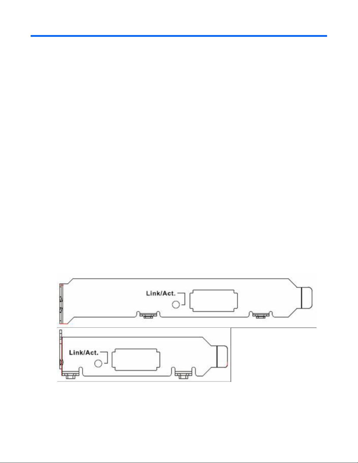
LED indicators
The NC510C adapter has a single CX4 connector and an LED indicator that shows Link/Act. (link
activity). Standard-height and low-profile brackets are shown below with CX4 connectors and the LED
indicator.
The NC510C 10 Gigabit Server Adapter LED indicator operates as described in the following table.
Introduction 6
Page 7

LED indicator Status Description
Link/Act. Off
No link to the adapter is established.
The adapter is not receiving power or
the cable connection is faulty.
On (Green)
Link to the adapter is established. The
adapter is receiving power and the
cable connection is good.
Flashing (Green)
The adapter is sending or receiving
network data at up to 10 Gbps.
Introduction 7
Page 8

Installing an adapter
In this section
Installation overview ................................................................................................................................. 8
Preventing electrostatic discharge............................................................................................................... 8
Installing an adapter in a server................................................................................................................. 9
Installing a low profile bracket................................................................................................................... 9
Installation overview
This section describes installation precautions, how to install the adapter, and how to connect the network
cable.
WARNING: To reduce the risk of personal injury or damage to the equipment, consult the safety
information and user documentation provided with the server before attempting the installation.
Many servers are capable of providing energy levels that are considered hazardous and are intended to
be serviced only by qualified personnel who have been trained to deal with these hazards. Do not
remove enclosures or attempt to bypass any interlocks that may be provided for the purpose of
removing these hazardous conditions.
WARNING: Installation of this adapter should be performed by individuals who are both qualified in
the servicing of computer equipment, and trained in the hazards associated with products capable of
producing hazardous energy levels.
This adapter is intended to be installed in Certified (UL or CSA) ITE equipment having instructions for
adding and removing user installed components such as PCI, PCI-X, and PCI Express devices. Refer to
the equipment instructions to verify that it is suitable for user installed components and that it has the
power capacity to support all of the installed components.
NOTE: Before removing the cover of your server, refer to the HP documentation for the proper
methods for installing a PCI Express card and avoiding electric shock hazards.
Preventing electrostatic discharge
To prevent damaging the system, be aware of the precautions you need to follow when setting up the
system or handling parts. A discharge of static electricity from a finger or other conductor may damage
system boards or other static-sensitive devices. This type of damage may reduce the life expectancy of the
device.
To prevent electrostatic damage:
• Avoid hand contact by transporting and storing products in static-safe containers.
• Keep electrostatic-sensitive parts in their containers until they arrive at static-free workstations.
• Place parts on a grounded surface before removing them from their containers.
• Avoid touching pins, leads, or circuitry.
• Always be properly grounded when touching a static-sensitive component or assembly.
Installing an adapter 8
Page 9

Installing an adapter in a server
See the HP ProLiant server documentation for additional information on how to safely install a PCI Express
card in the server.
CAUTION: If the server is not PCI Hot Plug compliant, power it down and unplug the power cord
from the power outlet before removing the server access panel. Failure to do so may damage the
adapter or server.
1. Power down the server.
2. Remove the power cord and server access panel. Then remove the cover bracket from a PCI Express
slot.
WARNING: To reduce the risk of personal injury from hot surfaces, allow the drives and the internal
system components to cool before touching them.
3. Firmly seat the adapter in a PCI Express slot and secure the adapter bracket.
NOTE: For 1U type servers you may need to replace the standard profile bracket with a low profile
bracket. See Installing a low profile bracket (on page 9).
4. Replace the access panel and plug in the power cord.
Installing a low profile bracket
You may have to install a low profile bracket to complete the product installation. The low profile bracket
replaces the existing standard profile bracket shipped on the product.
To install a low profile bracket:
1. Using a correctly sized Phillips head screwdriver, carefully remove the two board lock screws
located at the top and bottom of the connector. Some versions may have small spring clips on the
CX4 connector posts that also must be removed.
2. Remove the standard profile bracket and place the low profile bracket over the connector. Be careful
not to damage the connector or bend the low profile bracket.
3. Reinstall the two Phillips screws. Reinstallation of the spring clips (found on some versions) is optional
because the clips have negligible effect on the bracket support and EMI
Installing an adapter 9
Page 10

Specifications
In this section
CX4 Twin-axial cable.............................................................................................................................. 10
General specifications ............................................................................................................................ 10
Compliance........................................................................................................................................... 10
Power and environmental specifications.................................................................................................... 11
CX4 connector pinout description............................................................................................................. 11
CX4 Twin-axial cable
The NC510C adapter uses a 10Base-CX4 copper interface to deliver Gigabit Ethernet over four twinaxial copper cable pairs as specified in the IEEE 802.3ak standard. For troubleshooting and other
information about cabling, see the CX4 connector pinout description (on page 11).
General specifications
General
Value
specifications
Controller NETXEN NX2031
Data rate 10 Gbps, full-duplex
PCI bus 8 Lane (x8) PCI Express, compatible with x4 and x8 bus widths
Cable connector 4x InfiniBand® (SFF-8470)
Cable distance 15 meters with CX4 x4 twin-axial cable
Dimensions (LxW) 6.6 x 2.5 in (16.5 x 6.4 cm) without bracket
Compliance
Compliance Standard
IEEE
Safety UL Mark (US and Canada)
Emissions
802.1p (QoS), 802.1Q (VLANs), 802.3ae (10 Gigabit Ethernet), 802.3ak (CX4),
802.3x (flow control)
EN 60950
FCC Class A, VCCI Class A, BSMI Class A, CISPR 22 Class A, ACA Class A,
EN55022 Class A, EN55024-1, ICES-003 Class A, MIC Class A
Specifications 10
Page 11

Compliance Standard
Other PCIe v1.1
RoHS 5, Exemption 7
IPv4, IPv6
CE
ACPI 1.1a
Microsoft WHQL (Windows Hardware Quality Labs)
Server Design Guide version 3.0 (SDG 3.0)
Power and environmental specifications
Power and
Value
environmental
specifications
Operating Temperature: 32° to 131° F (0° to 55° C )
Humidity: 10% to 90% non-condensing
Non-operating Temperature: -85° to 185° F (-65° to 85° C)
Humidity: 5% to 95%
Power 1.68 A @ 12 V and 0.49 A @ 3.3 V maximum
CX4 connector pinout description
Pin Signal name Connector pin Signal name
S1 Rx_L0p S2 Rx_L0n
S3 Rx_L1p S4 Rx_L1n
S5 Rx_L2p S6 Rx_L2n
S7 Rx_L3p S8 Rx_L3n
S9 Tx_L3n S10 Tx_L3p
S11 Tx_L2n S12 Tx_L2p
S13 Tx_L1n S14 Tx_L1p
S15 Tx_L0n S16 Tx_L0p
G1 Signal Shield — —
G2 Signal Shield — —
G3 Signal Shield — —
G4 Signal Shield — —
G5 Signal Shield — —
G6 Signal Shield — —
G7 Signal Shield — —
G8 Signal Shield — —
G9 Link Shield — —
Specifications 11
Page 12

Specifications 12
Page 13

Regulatory compliance notices
In this section
Regulatory compliance identification numbers ........................................................................................... 13
Class A equipment ................................................................................................................................. 13
Modifications......................................................................................................................................... 13
Cables.................................................................................................................................................. 13
Canadian notice .................................................................................................................................... 14
Japanese class A notice .......................................................................................................................... 14
Korean regulatory notice......................................................................................................................... 14
BSMI notice........................................................................................................................................... 14
Laser compliance ................................................................................................................................... 14
Disposal of waste equipment by users in private households in the European Union....................................... 15
Regulatory compliance identification numbers
For the purpose of regulatory compliance certifications and identification, this product has been assigned
a unique regulatory model number. The regulatory model number can be found on the product nameplate
label, along with all required approval markings and information. When requesting compliance
information for this product, always refer to this regulatory model number. The regulatory model number is
not the marketing name or model number of the product.
Class A equipment
This equipment has been tested and found to comply with the limits for a Class A digital device, pursuant
to Part 15 of the FCC Rules. These limits are designed to provide reasonable protection against harmful
interference when the equipment is operated in a commercial environment. This equipment generates,
uses, and can radiate radio frequency energy and, if not installed and used in accordance with the
instructions, may cause harmful interference to radio communications. Operation of this equipment in a
residential area is likely to cause harmful interference, in which case the user will be required to correct
the interference at personal expense.
Modifications
The FCC requires the user to be notified that any changes or modifications made to this device that are
not expressly approved by Hewlett-Packard Company may void the user’s authority to operate the
equipment.
Cables
Connections to this device must be made with shielded cables with metallic RFI/EMI connector hoods in
order to maintain compliance with FCC Rules and Regulations.
Regulatory compliance notices 13
Page 14

Canadian notice
This Class A digital apparatus meets all requirements of the Canadian Interference-Causing Equipment
Regulations.
Cet appareil numérique de la classe A respecte toutes les exigences du Règlement sur le matériel
brouilleur du Canada.
Japanese class A notice
Korean regulatory notice
BSMI notice
Laser compliance
This product may be provided with an optical storage device (that is, CD or DVD drive) and/or fiber optic
transceiver. Each of these devices contains a laser that is classified as a Class 1 Laser Product in
accordance with US FDA regulations and the IEC 60825-1. The product does not emit hazardous laser
radiation.
Regulatory compliance notices 14
Page 15

Each laser product complies with 21 CFR 1040.10 and 1040.11 except for deviations pursuant to Laser
Notice No. 50, dated May 27, 2001; and with IEC 60825-1:1993/A2:2001.
WARNING: Use of controls or adjustments or performance of procedures other than those specified
herein or in the laser product's installation guide may result in hazardous radiation exposure. To
reduce the risk of exposure to hazardous radiation:
• Do not try to open the module enclosure. There are no user-serviceable components inside.
• Do not operate controls, make adjustments, or perform procedures to the laser device other than
those specified herein.
• Allow only HP Authorized Service technicians to repair the unit.
The Center for Devices and Radiological Health (CDRH) of the U.S. Food and Drug Administration
implemented regulations for laser products on August 2, 1976. These regulations apply to laser products
manufactured from August 1, 1976. Compliance is mandatory for products marketed in the United States.
Disposal of waste equipment by users in private households in the European Union
This symbol on the product or on its packaging indicates that this product must not be
disposed of with your other household waste. Instead, it is your responsibility to dispose of
your waste equipment by handing it over to a designated collection point for the recycling of
waste electrical and electronic equipment. The separate collection and recycling of your
waste equipment at the time of disposal will help to conserve natural resources and ensure
that it is recycled in a manner that protects human health and the environment. For more
information about where you can drop off your waste equipment for recycling, please
contact your local city office, your household waste disposal service or the shop where you
purchased the product.
Regulatory compliance notices 15
Page 16

Electrostatic discharge
In this section
Preventing electrostatic discharge............................................................................................................. 16
Grounding methods to prevent electrostatic discharge ................................................................................ 16
Preventing electrostatic discharge
To prevent damaging the system, be aware of the precautions you need to follow when setting up the
system or handling parts. A discharge of static electricity from a finger or other conductor may damage
system boards or other static-sensitive devices. This type of damage may reduce the life expectancy of the
device.
To prevent electrostatic damage:
• Avoid hand contact by transporting and storing products in static-safe containers.
• Keep electrostatic-sensitive parts in their containers until they arrive at static-free workstations.
• Place parts on a grounded surface before removing them from their containers.
• Avoid touching pins, leads, or circuitry.
• Always be properly grounded when touching a static-sensitive component or assembly.
Grounding methods to prevent electrostatic discharge
Several methods are used for grounding. Use one or more of the following methods when handling or
installing electrostatic-sensitive parts:
• Use a wrist strap connected by a ground cord to a grounded workstation or computer chassis. Wrist
straps are flexible straps with a minimum of 1 megohm ±10 percent resistance in the ground cords.
To provide proper ground, wear the strap snug against the skin.
• Use heel straps, toe straps, or boot straps at standing workstations. Wear the straps on both feet
when standing on conductive floors or dissipating floor mats.
• Use conductive field service tools.
• Use a portable field service kit with a folding static-dissipating work mat.
If you do not have any of the suggested equipment for proper grounding, have an authorized reseller
install the part.
For more information on static electricity or assistance with product installation, contact an authorized
reseller.
Electrostatic discharge 16
Page 17

Acronyms and abbreviations
CSA
Canadian Standards Association
DMA
direct memory access
IEEE
Institute of Electrical and Electronics Engineers
iSCSI
Internet Small Computer System Interface
MSI
Message Signaled Interrupt
MSI-X
Message Signaled Interrupt Extended
PCI Express
Peripheral Component Interconnect Express
RDMA
Remote Direct Memory Access
RSS
Receive-Side Scaling
TOE
TCP/IP Offload Engine
UTP
unshielded twisted pair
Acronyms and abbreviations 17
Page 18

Index
B
bracket, low profile 9
C
cable configuration 10
cable connectors 11
E
electrostatic discharge 8, 16
F
features 6
G
grounding methods 16
I
installation overview 8
installing adapters 9
N
NIC LEDs 6
R
regulatory compliance notices 13
S
specifications 10
V
ventilation 4
Index 18
 Loading...