

Page 1
MSA7X Series Enclosure
Backplane replacement
instructions
For updates, visit the HP website:
http://www.hp.com/support/manuals
© Copyright 2007 Hewlett-Packard Development Company, L.P.
The information contained herein is subject to change without notice.
The only warranties for HP products and services are set forth in the
express warranty statements accompanying such products and services.
Nothing herein should be construed as constituting an additional
warranty. HP shall not be liable for technical or editorial errors or
omissions contained herein.
Part number: 436513-001
First edition: 02/2007
*436513-001*
.
About this document
This document details procedures for replacing a failed
backplane in an MSA7X Series Enclosure.
Before you begin
CAUTION: Before removing the failed component, make sure
that you have the replacement part available. Removing a
component impacts the airflow and cooling ability of the
device.
To prevent improper cooling and thermal damage, do not
operate the storage enclosure unless all bays are populated
with either a component or a blank.
Do not remove more than one component or blank from the
enclosure at a time. Doing so impacts the airflow and cooling
ability of the device. To avoid possible overheating, insert the
new or replacement component as quickly as possible. If the
internal temperature exceeds acceptable limits, the enclosure
may overheat and automatically shut down or restart.
Parts can be damaged by electrostatic discharge. Use proper
anti-static protection.
Verifying component failure
Before replacing the midplane, use the following methods to
verify component failure:
• Check the following component status LEDs as identified in
the following tables:
• Hard drives—test with known good hard drives.
• I/O module—test with known good I/O module.
• Fan module—test with known good fan module.
• Check the host log for errors.
Hard drive LED combinations
Online/activity LED
(green)
On, off, or flashing
On, off, or flashing Steadily blue
On
On Off
Fault/UID LED
(amber/blue)
Alternating amber
and blue
Amber, flashing
regularly (1 Hz)
Interpretation
The drive has failed, or
a predictive failure
alert has been received
for this drive; it also
has been selected by a
management
application.
The drive is operating
normally, and it has
been selected by a
management
application.
A predictive failure
alert has been received
for this drive.
Replace the drive as
soon as possible.
The drive is online, but
it is not currently active.
Page 2
Hard drive LED combinations
Online/activity LED
(green)
Flashing regularly
(1 Hz)
Flashing regularly
(1 Hz)
Flashing irregularly
Flashing irregularly Off
Off Steadily amber
Off
Off Off
Fault/UID LED
(amber/blue)
Amber, flashing
regularly (1 Hz)
Off
Amber, flashing
regularly (1 Hz)
Amber, flashing
regularly (1 Hz)
Interpretation
Do not remove the
drive. Removing a
drive may
terminate the
current operation
and cause data
loss.
The drive is part of an
array that is
undergoing capacity
expansion or a stripe
size migration, but a
predictive failure alert
has been received for
this drive. To minimize
the risk of data loss, do
not replace the drive
until the expansion or
migration is complete.
Do not remove the
drive. Removing a
drive may
terminate the
current operation
and cause data
loss.
The drive is rebuilding,
or it is part of an array
that is undergoing
capacity expansion or
a stripe size migration.
The drive is active, but
a predictive failure
alert has been received
for this drive. Replace
the drive as soon as
possible.
The drive is active and
it is operating
normally.
A critical fault
condition has been
identified for this drive
and the controller has
placed it offline.
Replace the drive as
soon as possible.
A predictive failure
alert has been received
for this drive. Replace
the drive as soon as
possible.
The drive is offline, a
spare, or not
configured as part of
an array.
I/O module and system fan LEDs
Item Description
I/O module LED Green = System activity
Amber = Fault condition
Off = No system activity
System fan LED Green = Normal operation
Amber = Fault condition
Off = Fan unseated from connector or
failed
Removing the midplane
To remove the midplane:
1. Power down the enclosure:
a. Power down any attached servers. See the server
documentation.
b. Press the Power On/Standby button on the enclosure.
c. Wait for the system power LED to go from green to
amber.
d. Disconnect the power cords.
CAUTION: Be sure that the server is the first unit to be
powered down and the last to be powered back up.
Taking this precaution ensures that the system does not
erroneously mark the drives as failed when the server is
powered up.
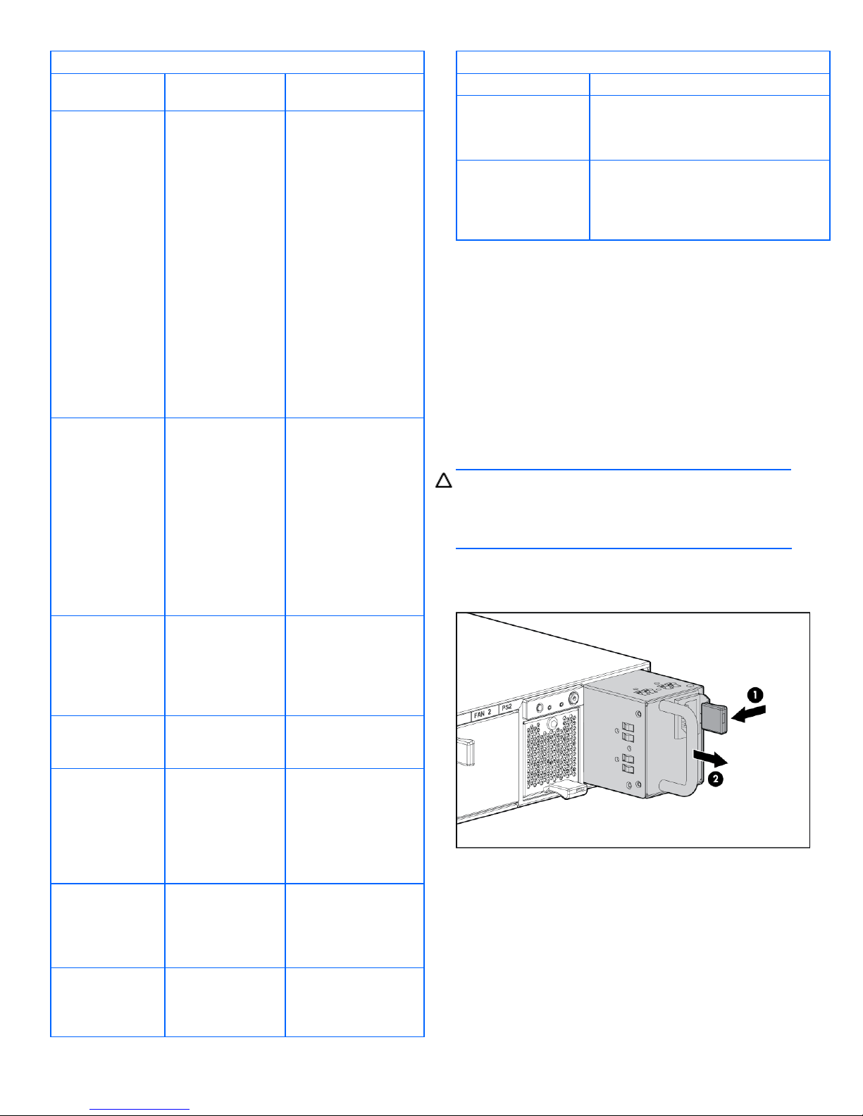
2. Remove the power supplies by disconnecting the power
cord from each supply, pressing the lever inward (1) and
sliding the component out of the chassis (2).
3. Remove the system fans by pressing up on the lever on
each fan (1) and sliding the fan out of the chassis (2).
Page 3

4. Remove the I/O module by squeezing the lever (1) and
rotating down (2), and then sliding the I/O module out of
the chassis (3).
b. Use a finger to slide out and remove the board from
the chassis (2).
9. Remove the riser board by loosening the thumbscrew (1)
and lifting the board out of the chassis (2).
5. Remove the I/O module blank as you did the I/O module.
6. Extend or remove the storage enclosure from the rack in
which it may be installed:
a. Loosen the front panel thumbscrews that secure the
enclosure faceplate to the front of the rack.
b. Disconnect the cabling and extend or remove the
enclosure from the rack.
7. Remove the access panel:
a. Lift the access panel latch (1).
b. Slide the access panel to the rear (2).
10. Disconnect the cables (1 and 2) from the midplane.
11. Lift the lever up to disengage the midplane from the
backplane (1).
12. Tilt the midplane up and remove it from the chassis (2).
8. Remove the 7-segment display board:
a. Pull the pin out to release the board (1).
Page 4

13. Tilt the backplane up from the bottom and lift it out of the
chassis (2).
Installing the backplane
To install the backplane, reverse the removal procedure:
1. Insert the backplane into the chassis, securing it with the
screw.
2. Install the midplane, riser board, 7-segment display board,
I/O module and blank, fans, and power supplies.
3. Install the access panel.
4. Insert the enclosure into the rack and power up the
enclosure.
Verifying component replacement
After replacing the backplane, check the hard drive status LEDs.
 Loading...