

Page 1
Memory Module Replacement
Instructions
Before you begin
Observe the following requirements before removing and
replacing memory.
WARNING: Never open the cover while the power cord
is attached. You might damage your computer or be
injured by the spinning fan blades.
WARNING: Avoid touching sharp edges inside the
computer.
CAUTION: Static electricity can damage the electronic
components inside the computer. Discharge static electricity
by touching the metal cage of the computer before touching
any internal parts or electronic components.
854285-001
Memory compatibility
The computer uses SODIMMs (small outline dual in-line
memory modules) that must meet the following
requirements:
● 204-pin
● DDR4-2133
● Unbuffered, non-ECC (64-bit)
● 1.2 V
● 16 GB maximum installable memory
Because the memory uses dual channels, you must use the
same memory module type for both sockets.
Tools needed
Phillips #2 screwdriver
Hex tool
Small screws are easily lost. Remove screws over a surface
that enables you to retrieve them if they fall.
Troubleshooting
If the computer displays a memory error after you have
turned it back on, turn the computer off and unplug the
power cord. Open up the memory compartment and make
sure the memory module is inserted all the way into the slot,
and then press down on it to be sure it is firmly seated.
NOTE: The actual memory transfer speed might vary,
based on the processor used in your computer.
NOTE: Memory performance might vary due to different
system configurations.
Removing the memory module
1. Disconnect the power cord and all attached cables
from the back of the computer.
854285-001 1
Page 2
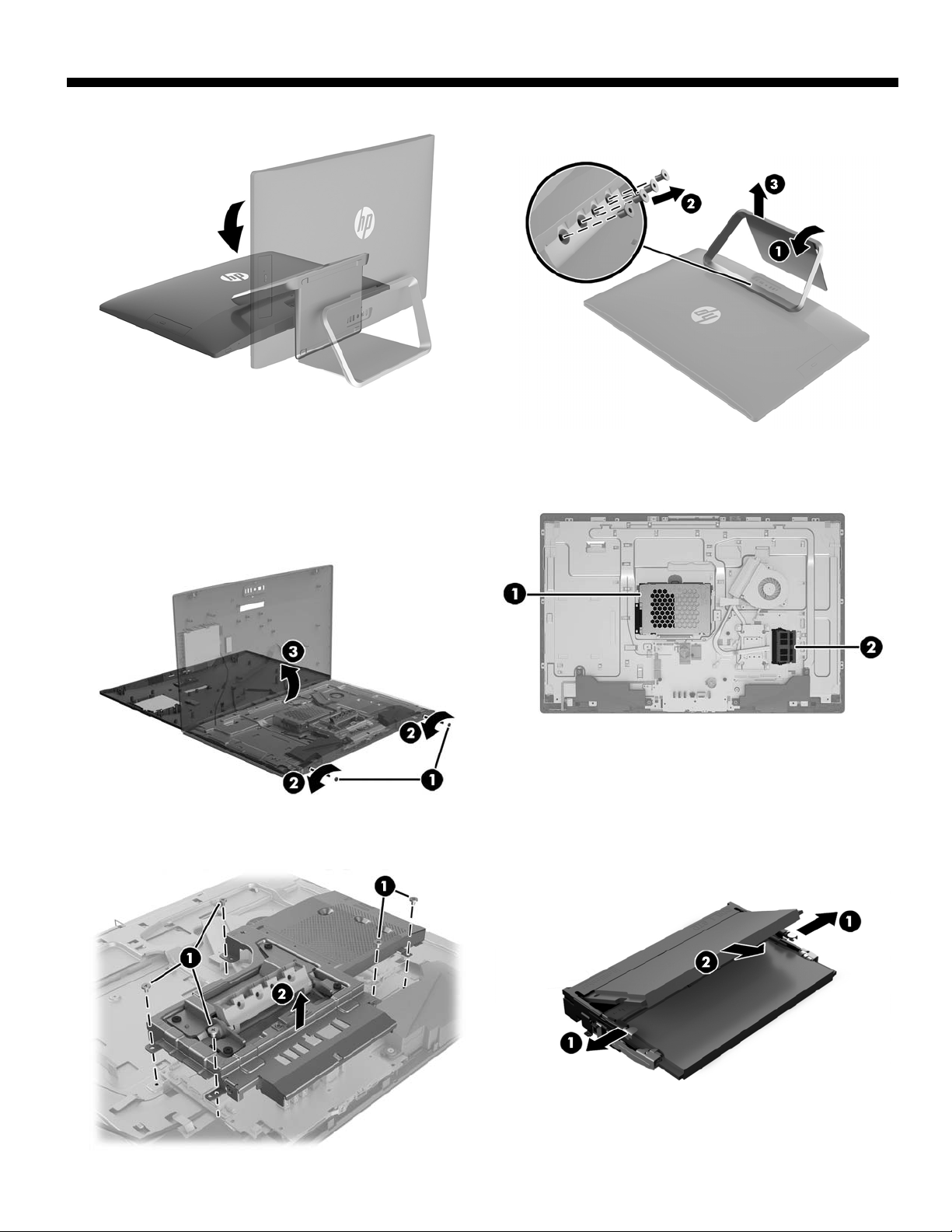
2. Using caution, lay the computer down on a flat surface
covered with a soft cloth.
4. To remove the rear cover, remove the two screw covers
(1) and two Phillips screws (2) located in the bottom of
the cover. Lift off the cover, and then place it upside
down next to the computer (3). The optical drive is
mounted on the inside of the rear cover, and a cable
connects it to the system board.
3. To remove the stand, rotate it upward (1), remove the
four hex screws (2), and then lift the stand up and off
the computer (3).
5. Locate the memory modules:
1. Hard drive
2. Memory modules
6. Remove the five Phillips screws that secure the system
board cover (1), and then lift the cover off the
computer (2).
7. Spread the two retention clips outward (1) until the
memory module tilts up at a 45-degree angle. Remove
the module (2). Use the same procedure to remove
both memory modules.
854285-001 2
Page 3

8. Touch the replacement memory module bag to the metal
of the computer, and then remove the replacement
memory module from the bag.
Replacing the memory module
1. Align the notched edge of the module with the tab in the
slot, and then press the module into the slot at an angle
until it is seated (1). Press down on the module until the
side retention clips snap into place (2). NOTE: Memory
modules are notched to prevent incorrect insertion.
2. Position the system board cover over the system board
(1), and then replace the five Phillips screws (2).
854285-001 3
Page 4

3. Align the rear cover with the computer and press it
down until it snaps into place (1). Replace the two
Phillips screws (2), and then replace the screw covers
(3).
5. Plug the power cord and any additional cables into the
back of the computer.
4. Position the top of the stand on the computer (1), and
then replace the four hex screws (2). Rotate the stand
downward (3).
6. Press the power button to turn on the computer.
© Copyright 2016 HP Development Company, L.P.
The information contained herein is subject to change without notice. The only warranties for
HP products and services are set forth in the express warranty statements accompanying such
products and services. Nothing herein should be construed as constituting an additional warranty.
HP shall not be liable for technical or editorial errors or omissions contained herein.
First Edition: May 2016
PRI NTE R: Repl ace thi s box wi th Prin te d- In (PI )
St ate ment( s) as pe r spec.
NOTE: This box is simply a placeholder. PI
St ate ment( s) do n ot ha ve to fit insid e the b ox
but sh ould be pl aced in thi s area .
854285-001 4
 Loading...