

Page 1
M274
M277
M252n M252dw
ColorLaserJet Pro M252
ColorLaserJet Pro MFP M274
ColorLaserJet Pro MFP M277
Troubleshooting manual
www.hp.com/support/colorljM252
www.hp.com/support/colorljM274MFP
www.hp.com/support/colorljMFPM277
For printer part removal and part number
information, see the Repair Manual
Page 2

Page 3

HP Color LaserJet Pro M252, HP Color
LaserJet Pro MFP M274 and M277
Troubleshooting Manual
Page 4

Copyright and License
© Copyright 2015 HP Development Company,
L.P.
Reproduction, adaptation, or translation
without prior written permission is prohibited,
except as allowed under the copyright laws.
The information contained herein is subject to
change without notice.
The only warranties for HP products and
services are set forth in the express warranty
statements accompanying such products and
services. Nothing herein should be construed
as constituting an additional warranty. HP shall
not be liable for technical or editorial errors or
omissions contained herein.
Edition 2, 10/2015
Page 5

Conventions used in this guide
TIP: Helpful hints or shortcuts.
Reinstallation tip: Reinstallation helpful hints, shortcuts, or considerations.
NOTE: Information that explains a concept or how to complete a task.
IMPORTANT: Information that help the user to avoid potential printer error conditions.
CAUTION: Procedures that the user must follow to avoid losing data or damaging the printer.
WARNING! Procedures that the user must follow to avoid personal injury, catastrophic loss of data, or
extensive damage to the printer.
ENWW iii
Page 6

iv Conventions used in this guide ENWW
Page 7

For additional service and support information
HP service personnel, go to the Service Access Work Bench (SAW) at http://h41302.www4.hp.com/km/saw/
home.do.
Channel partners, go to HP Channel Services Network (CNS) at https://h30125.www3.hp.com/hpcsn.
●
To access HP PartSurfer information from any mobile device, go to http://partsurfermobile.hp.com/ or
scan the Quick Response (QR) code below.
●
Install and congure
●
Printer specications
●
Up-to-date control panel message (CPMD) troubleshooting
●
Solutions for printer issues and emerging issues
●
Remove and replace part instructions and videos
●
Service advisories
●
Warranty and regulatory information
ENWW v
Page 8

vi For additional service and support information ENWW
Page 9

Table of contents
1 Theory of operation ....................................................................................................................................... 1
Related documentation and software ................................................................................................................... 2
Basic operation ...................................................................................................................................................... 3
Sequence of operation ........................................................................................................................ 4
Formatter-control system ..................................................................................................................................... 5
Sleep delay .......................................................................................................................................... 5
Printer job language (PJL) ................................................................................................................... 5
Printer management language (PML) ................................................................................................. 6
Control panel ....................................................................................................................................... 6
Walk-up USB (touchscreen models only) ............................................................................................ 6
Wireless (wireless models only) .......................................................................................................... 6
Low end data model (LEDM) ................................................................................................................ 6
Advanced control language (ACL) overview ........................................................................................ 6
Near eld communication (NFC) (wireless models only) .................................................................... 7
CPU ....................................................................................................................................................... 7
Input/output ........................................................................................................................................ 7
USB .................................................................................................................................... 7
USB hosts .......................................................................................................................... 7
10/100 networking ........................................................................................................... 7
Fax (M277 models only) .................................................................................................... 7
Memory ................................................................................................................................................ 7
Firmware ........................................................................................................................... 7
Nonvolatile random access memory (NVRAM) ................................................................. 7
Flash memory ................................................................................................................... 7
Random access memory (RAM) ........................................................................................ 8
HP Memory enhancement technology (MEt) .................................................................... 8
Engine-control system .......................................................................................................................................... 9
Engine control unit (ECU) .................................................................................................................. 10
DC controller ................................................................................................................... 10
High-voltage power supply ............................................................................................ 11
Motors ............................................................................................................................. 11
Fans ................................................................................................................................. 12
ENWW vii
Page 10

Solenoids ......................................................................................................................... 12
Switches .......................................................................................................................... 13
Sensors ........................................................................................................................... 14
Low-voltage power supply ................................................................................................................ 15
Overcurrent/overvoltage protection .............................................................................. 15
Low-voltage power supply unit failure detection .......................................................... 15
Engine laser scanner system ............................................................................................................................... 16
Laser failure detection ...................................................................................................................... 16
Image formation system ..................................................................................................................................... 17
Image formation process .................................................................................................................. 17
Step 1: Primary charging ................................................................................................ 17
Step 2: Laser-beam exposure ......................................................................................... 19
Step 3: Development ...................................................................................................... 19
Step 4: Primary transfer ................................................................................................. 20
Step 5: Secondary transfer ............................................................................................. 20
Step 6: Separation ........................................................................................................... 21
Step 7: Fusing .................................................................................................................. 21
Step 8: Drum cleaning ..................................................................................................... 21
Toner cartridges ................................................................................................................................ 23
Design ............................................................................................................................. 23
Memory chip .................................................................................................................... 24
HP Cartridges with JetIntelligence ................................................................................. 24
HP Cartridge Policy ....................................................................................... 24
Anti-theft or cartridge protection ................................................................ 24
Intermediate transfer belt (ITB) assembly ........................................................................................ 24
Engine pickup, feed, and delivery system ........................................................................................................... 26
Priority input slot pickup ................................................................................................................... 29
Cassette pickup ................................................................................................................................. 30
Duplexing unit ................................................................................................................................... 30
Duplex reverse and duplex feed control ........................................................................ 31
Duplex pickup operation ................................................................................................. 31
Jam detection .................................................................................................................................... 32
Scanning and image capture system .................................................................................................................. 33
Automatic document feeder (ADF) system ......................................................................................................... 34
ADF simplex operation ...................................................................................................................... 34
Fax functions and operation (fax models only) .................................................................................................. 35
Computer and network security features ......................................................................................... 35
PSTN operation .................................................................................................................................. 35
Receive faxes when you hear fax tones ............................................................................................ 35
Distinctive ring function .................................................................................................................... 36
Set up the distinctive ring function ................................................................................ 36
viii ENWW
Page 11

Fax by using voice over IP (VOIP) services ........................................................................................ 36
The fax subsystem ............................................................................................................................ 37
Fax card in the fax subsystem ........................................................................................................... 37
Safety isolation ............................................................................................................... 37
Safety-protection circuitry ............................................................................................. 37
Data path ......................................................................................................................... 37
Hook state ....................................................................................................................... 38
Downstream device detection ........................................................................................ 38
Hook switch control ........................................................................................................ 38
Ring detect ...................................................................................................................... 38
Line current control ......................................................................................................... 38
Billing or metering tone lters ....................................................................................... 39
Fax page storage in ash memory .................................................................................................... 39
Stored fax pages ............................................................................................................. 39
Advantages of ash memory storage ............................................................................ 39
2 Solve problems ............................................................................................................................................ 41
Troubleshooting process ..................................................................................................................................... 42
Solve problems checklist ................................................................................................................... 42
Print the menu map ........................................................................................................ 43
Print a conguration page .............................................................................................. 43
Print the service page (includes the event log) .............................................................. 44
Determine the problem source ......................................................................................................... 44
Troubleshooting owchart ............................................................................................. 44
Power subsystem .............................................................................................................................. 45
Power-on checks ............................................................................................................. 45
Power-on troubleshooting overview ........................................................... 45
Control panel checks ......................................................................................................................... 49
Tools for troubleshooting .................................................................................................................................... 50
Individual component diagnostics .................................................................................................... 50
Tools for troubleshooting: LED diagnostics ................................................................... 50
Network port LEDs ....................................................................................... 50
Two-line control panel LEDs ........................................................................ 51
Tools for troubleshooting: Engine diagnostics .............................................................. 51
Engine test .................................................................................................... 51
Diagrams ........................................................................................................................................... 52
Diagrams: Block diagrams .............................................................................................. 52
Sensors and switches ................................................................................... 52
Diagrams: Printed circuit assembly (PCA) connector locations ..................................... 53
Diagrams: Formatter connections ............................................................... 53
Diagrams: DC controller connections ........................................................... 55
ENWW ix
Page 12

Diagrams: External plug and port locations ................................................................... 56
Diagrams: Locations of major components ................................................................... 57
Major components (printer base) ................................................................. 57
Motors and fan .............................................................................................. 58
Rollers (printer base) .................................................................................... 59
PCAs (printer base) ....................................................................................... 60
Diagrams: Timing chart .................................................................................................. 61
Diagrams: Circuit diagrams ............................................................................................. 62
Advanced conguration with HP Embedded Web Server (EWS) and HP Device Toolbox
(Windows) .......................................................................................................................................... 63
Print quality troubleshooting tools .................................................................................................. 66
Repetitive defects ruler .................................................................................................. 66
Use a ruler to measure between repetitive defects ..................................... 66
Calibrate the printer to align the colors ......................................................................... 70
Control panel menus ......................................................................................................................... 71
2-line control-panel view (M252n model) ...................................................................... 71
Touchscreen control-panel view (M252dw model) ........................................................ 72
Home screen layout ...................................................................................... 73
Touchscreen control-panel view (M274 and M277 models) .......................................... 74
Home screen layout ...................................................................................... 75
Setup menu ..................................................................................................................... 76
HP Web Services menu ................................................................................. 76
Reports menu ............................................................................................... 77
Self Diagnostics menu .................................................................................. 79
Fax Setup menu ............................................................................................ 79
System Setup menu ..................................................................................... 82
Service menu ................................................................................................ 86
Network Setup menu .................................................................................... 88
Quick Forms menu ........................................................................................ 89
Function specic menus ................................................................................................. 90
USB menu ..................................................................................................... 90
Fax Menu (M277 models only) ..................................................................... 90
Copy menu (M274 and M277 models only) .................................................. 92
Scan menu (M274 and M277 models only) .................................................. 94
Apps .............................................................................................................. 94
Control panel message document (CPMD) ........................................................................................ 95
Control-panel message types ......................................................................................... 95
Control-panel messages and event log entries ............................................................. 95
Alpha Error Messages ................................................................................... 95
49.XX.YY Error Messages ............................................................................ 105
50.XX fuser errors ...................................................................................... 106
x ENWW
Page 13

51.XX and 52 Laser/Scanner Errors ........................................................... 107
54.XX Error Messages ................................................................................ 108
55.XXXX Error Messages ............................................................................ 108
57.XX Error Messages ................................................................................ 109
58.XX Error Messages ................................................................................ 109
59.XX Error Messages ................................................................................ 110
79 Errors ..................................................................................................... 111
Tools for troubleshooting: Event log messages ............................................................................. 112
Print an event log .......................................................................................................... 112
View the event log ........................................................................................................ 112
Event-log messages ..................................................................................................... 113
Solve image quality problems ........................................................................................................................... 119
Improve print quality ...................................................................................................................... 119
Repetitive defects ruler ................................................................................................ 119
Print from a dierent software program ..................................................................... 120
Check the paper-type setting for the print job ............................................................ 120
Check the paper type setting (Windows) ................................................... 120
Check the paper type setting (Mac OS X) ................................................... 120
Check toner-cartridge status ....................................................................................... 121
Print and interpret the print quality page .................................................................... 121
Clean the printer ........................................................................................................... 122
Print a cleaning page .................................................................................. 122
Clean the scanner glass strip and platen ................................................... 123
Visually inspect the toner cartridge ............................................................................. 123
Check paper and the printing environment .................................................................. 124
Step one: Use paper that meets HP specications .................................... 124
Step two: Check the environment .............................................................. 124
Calibrate the printer to align the colors ....................................................................... 124
Check other print job settings ...................................................................................... 125
Check the EconoMode settings .................................................................. 125
Adjust color settings (Windows) ................................................................ 126
Try a dierent print driver ............................................................................................ 127
Clean the printer ................................................................................................................................................ 129
Print a cleaning page ....................................................................................................................... 129
Clean the scanner glass strip and platen ........................................................................................ 129
Clean the pickup and separation rollers ......................................................................................... 130
Clean the pickup rollers and separation pad in the document feeder ........................................... 131
Clean the touchscreen ..................................................................................................................... 131
Solve paper-handling problems ........................................................................................................................ 132
Printer feeds incorrect page size .................................................................................................... 132
Printer pulls from incorrect tray ..................................................................................................... 132
ENWW xi
Page 14

Printer will not duplex or duplexes incorrectly ............................................................................... 132
Paper does not feed from Tray 2 .................................................................................................... 133
Output is curled or wrinkled ............................................................................................................ 133
Printer does not pick up paper or misfeeds .................................................................................... 134
The printer does not pick up paper .............................................................................. 134
The printer picks up multiple sheets of paper ............................................................. 134
The document feeder jams, skews, or picks up multiple sheets of paper (M274
and M277 models) ........................................................................................................ 135
Paper does not feed automatically .............................................................................. 135
Prevent paper jams ............................................................................................................................................ 136
Clear paper jams ................................................................................................................................................ 137
Introduction ..................................................................................................................................... 137
Experiencing frequent or recurring paper jams? ............................................................................ 137
Paper jam locations ......................................................................................................................... 138
Clear paper jams in the document feeder (M274 and M277 models only) .................................... 140
Clear paper jams in the single-sheet slot (Tray 1) .......................................................................... 142
Clear paper jams in Tray 2 ............................................................................................................... 144
Clear paper jams in the rear door and the fuser area (simplex models) ........................................ 147
Clear paper jams in the output bin .................................................................................................. 149
Clear paper jams in the duplexer (duplex models) ......................................................................... 150
Solve performance problems ............................................................................................................................ 152
Solve connectivity problems ............................................................................................................................. 153
Solve USB connection problems ..................................................................................................... 153
Solve wired network problems ....................................................................................................... 153
Introduction .................................................................................................................. 153
Poor physical connection .............................................................................................. 153
The computer is using the incorrect IP address for the printer ................................... 153
The computer is unable to communicate with the printer ........................................... 154
The printer is using incorrect link and duplex settings for the network ..................... 154
New software programs might be causing compatibility problems ........................... 154
The computer or workstation might be set up incorrectly .......................................... 154
The printer is disabled, or other network settings are incorrect ................................. 154
Solve wireless network problems ................................................................................................... 154
Introduction .................................................................................................................. 154
Wireless connectivity checklist ..................................................................................... 155
The printer does not print after the wireless conguration completes ...................... 155
The printer does not print, and the computer has a third-party rewall installed ..... 156
The wireless connection does not work after moving the wireless router or printer . 156
Cannot connect more computers to the wireless printer ............................................ 156
The wireless printer loses communication when connected to a VPN ........................ 156
The network does not appear in the wireless networks list ........................................ 156
xii ENWW
Page 15

The wireless network is not functioning ...................................................................... 156
Perform a wireless network diagnostic test ................................................................ 157
Reduce interference on a wireless network ................................................................. 157
Service mode functions ..................................................................................................................................... 158
Service menu ................................................................................................................................... 158
Secondary service menu ................................................................................................................. 159
Printer resets ................................................................................................................................... 160
Restore the factory-set defaults .................................................................................. 160
NVRAM initialization ..................................................................................................... 161
Super NVRAM initialization ........................................................................................... 161
Solve fax problems (fax models only) ............................................................................................................... 163
Checklist for solving fax problems .................................................................................................. 163
Perform a fax diagnostic test ......................................................................................................... 164
Solve general fax problems ............................................................................................................ 164
Faxes are sending slowly .............................................................................................. 164
Print quality of a photo is poor or prints as a gray box. ............................................... 165
Fax quality is poor ......................................................................................................... 165
You touched the Cancel button to cancel a fax, but the fax was still sent ............. 166
No fax address book button displays ........................................................................... 166
Not able to locate the fax settings in HP Web Jetadmin .............................................. 166
The header is appended to the top of the page when the overlay option is enabled . 166
A mix of names and numbers is in the recipients box .................................................. 166
A one-page fax prints as two pages ............................................................................. 167
A document stops in the document feeder in the middle of faxing ............................ 167
The volume for sounds coming from the fax accessory is too high or too low ........... 167
Use fax over VoIP networks .......................................................................................... 167
Solve problems receiving faxes ...................................................................................................... 167
Solve problems sending faxes ........................................................................................................ 172
Fax error messages on the control panel ....................................................................................... 173
The No Fax Detected message displays ....................................................................... 173
The Communication error message appears ............................................................... 173
No Dial Tone .................................................................................................................. 174
The Fax is busy message appears ................................................................................ 175
The No fax answer message appears ........................................................................... 175
Document feeder paper jam ......................................................................................... 176
The Fax storage is full message appears ..................................................................... 176
Scanner error ................................................................................................................ 176
The control panel displays a Ready message with no attempt to send the fax .......... 176
The control panel displays the message "Storing page 1" and does not progress
beyond that message ................................................................................................... 177
Faxes can be received, but not sent ............................................................................. 177
ENWW xiii
Page 16

Printer is password protected ...................................................................................... 177
Unable to use fax functions from the control panel .................................................... 178
Unable to use speed dials ............................................................................................. 178
Unable to use group dials ............................................................................................. 178
Receive a recorded error message from the phone company when trying to send
a fax ............................................................................................................................... 178
Unable to send a fax when a phone is connected to the printer .................................. 179
Troubleshoot fax codes and trace reports ...................................................................................... 179
View and interpret fax error codes ............................................................................... 179
Fax trace report ............................................................................................................ 180
Fax logs and reports ........................................................................................................................ 180
Print all fax reports ....................................................................................................... 180
Print individual fax reports ........................................................................................... 181
Set the fax error report ................................................................................................. 181
Set the fax-error-correction mode ................................................................................................. 181
Change the fax speed ...................................................................................................................... 182
Use fax on a DSL, PBX, or ISDN system ........................................................................................... 182
DSL ................................................................................................................................ 182
PBX ................................................................................................................................ 182
ISDN ............................................................................................................................... 183
Solve email problems ........................................................................................................................................ 184
Cannot connect to the email server ................................................................................................ 184
Validate the SMTP gateway (Windows) .......................................................................................... 184
Validate the LDAP gateway (Windows) ........................................................................................... 184
Update the rmware ......................................................................................................................................... 185
Method one: Update the rmware using the control panel ........................................................... 185
Method two: Update the rmware using the Firmware Update Utility .......................................... 186
Appendix A Certicates of volatility ............................................................................................................... 187
Certicate of volatility ....................................................................................................................................... 188
Index ........................................................................................................................................................... 195
xiv ENWW
Page 17

List of tables
Table 1-1 Sequence of operation .......................................................................................................................................... 4
Table 1-2 Printer motors1 ................................................................................................................................................... 11
Table 1-3 Printer fan ........................................................................................................................................................... 12
Table 1-4 Solenoids ............................................................................................................................................................ 12
Table 1-5 Switches .............................................................................................................................................................. 13
Table 1-6 Sensors ............................................................................................................................................................... 14
Table 1-7 Image formation process ................................................................................................................................... 17
Table 1-8 Switches and sensors for the pickup, feed, and delivery system ...................................................................... 27
Table 1-9 Motors and solenoids for the pickup, feed, and delivery system ...................................................................... 28
Table 2-1 Troubleshooting owchart ................................................................................................................................. 44
Table 2-2 Formatter connections—M252 models ............................................................................................................. 53
Table 2-3 Formatter connections—M277 models ............................................................................................................. 54
Table 2-4 DC controller connectors .................................................................................................................................... 55
Table 2-5 Major components (printer base) ....................................................................................................................... 57
Table 2-6 Rollers (printer base) .......................................................................................................................................... 59
Table 2-7 Main PCAs (printer base) ..................................................................................................................................... 60
Table 2-8 Repetitive image defects .................................................................................................................................... 66
Table 2-9 HP Web Services menu ....................................................................................................................................... 76
Table 2-10 Reports menu ................................................................................................................................................... 77
Table 2-11 Self Diagnostics menu ...................................................................................................................................... 79
Table 2-12 Fax Setup menu ................................................................................................................................................ 79
Table 2-13 System Setup menu ......................................................................................................................................... 82
Table 2-14 Service menu .................................................................................................................................................... 86
Table 2-15 Network Setup menu ........................................................................................................................................ 88
Table 2-16 Quick Forms menu ............................................................................................................................................ 89
Table 2-17 USB menu ......................................................................................................................................................... 90
Table 2-18 Fax Menu ........................................................................................................................................................... 90
Table 2-19 Copy menu ........................................................................................................................................................ 92
Table 2-20 Scan menu ........................................................................................................................................................ 94
Table 2-21 Event-log messages (X=0: black cartridge, X=1: cyan cartridge, X=2: magenta cartridge, X=3: yellow
cartridge) .............................................................................................................................................................................. 113
Table 2-22 Fax event log codes ........................................................................................................................................ 118
ENWW xv
Page 18

Table 2-23 Repetitive image defects ............................................................................................................................... 119
Table 2-24 Solve performance problems ......................................................................................................................... 152
Table 2-25 Service menu .................................................................................................................................................. 158
Table 2-26 Secondary service menu ................................................................................................................................ 159
Table 2-27 Solve problems receiving faxes ..................................................................................................................... 167
Table 2-28 Solve problems sending faxes ....................................................................................................................... 172
xvi ENWW
Page 19

List of gures
Figure 1-1 Basic operation .................................................................................................................................................... 3
Figure 1-2 Engine-control system ........................................................................................................................................ 9
Figure 1-3 Engine control unit ............................................................................................................................................ 10
Figure 1-4 High-voltage power supply ............................................................................................................................... 11
Figure 1-5 Low-voltage power supply ............................................................................................................................... 15
Figure 1-6 Laser scanner system ....................................................................................................................................... 16
Figure 1-7 Image-formation process ................................................................................................................................. 17
Figure 1-8 Primary charging ............................................................................................................................................... 18
Figure 1-9 Laser-beam exposure ....................................................................................................................................... 19
Figure 1-10 Development ................................................................................................................................................... 19
Figure 1-11 Primary transfer .............................................................................................................................................. 20
Figure 1-12 Secondary transfer ......................................................................................................................................... 20
Figure 1-13 Separation ....................................................................................................................................................... 21
Figure 1-14 Fusing .............................................................................................................................................................. 21
Figure 1-15 Drum cleaning ................................................................................................................................................. 22
Figure 1-16 Toner cartridge system ................................................................................................................................... 23
Figure 1-17 ITB assembly ................................................................................................................................................... 25
Figure 1-18 Paper path ....................................................................................................................................................... 26
Figure 1-19 Switches and sensors for the pickup, feed, and delivery system .................................................................. 27
Figure 1-20 Motors and solenoids for the pickup, feed, and delivery system .................................................................. 28
Figure 1-21 Duplexing unit controls ................................................................................................................................... 30
Figure 2-1 Engine test page ................................................................................................................................................ 46
Figure 2-2 Engine test page ................................................................................................................................................ 47
Figure 2-3 Engine test page ................................................................................................................................................ 48
Figure 2-4 Engine test page ................................................................................................................................................ 51
Figure 2-5 Sensors and switches ........................................................................................................................................ 52
Figure 2-6 Formatter connections—M252 models ........................................................................................................... 53
Figure 2-7 Formatter connections—M274 and M277 models .......................................................................................... 54
Figure 2-8 DC controller PCA connectors ........................................................................................................................... 55
Figure 2-9 Major components (printer base) ..................................................................................................................... 57
Figure 2-10 Motors and fan ................................................................................................................................................ 58
Figure 2-11 Rollers (printer base) ...................................................................................................................................... 59
ENWW xvii
Page 20

Figure 2-12 Main PCAs (printer base) ................................................................................................................................. 60
Figure 2-13 General timing chart ....................................................................................................................................... 61
Figure 2-14 General circuit diagram (printer base) ............................................................................................................ 62
Figure 2-15 Examples of repetitive defects ....................................................................................................................... 67
Figure 2-16 Place the ruler on the page ............................................................................................................................. 68
Figure 2-17 Locate the next repetitive defect ................................................................................................................... 68
Figure 2-18 Determine the defective assembly ................................................................................................................. 69
Figure 2-19 Print quality page ......................................................................................................................................... 122
Figure A-1 Certicate of volatility M252 (1 of 2) .............................................................................................................. 188
Figure A-2 Certicate of volatility M252 (2 of 2) .............................................................................................................. 189
Figure A-3 Certicate of volatility M274 (1 of 2) .............................................................................................................. 190
Figure A-4 Certicate of volatility M274 (2 of 2) .............................................................................................................. 191
Figure A-5 Certicate of volatility M277 (1 of 2) .............................................................................................................. 192
Figure A-6 Certicate of volatility M277 (2 of 2) .............................................................................................................. 193
xviii ENWW
Page 21

1 Theory of operation
●
Related documentation and software
●
Basic operation
●
Formatter-control system
●
Engine-control system
●
Engine laser scanner system
●
Image formation system
●
Engine pickup, feed, and delivery system
●
Scanning and image capture system
●
Automatic document feeder (ADF) system
●
Fax functions and operation (fax models only)
ENWW 1
Page 22

Related documentation and software
HP service personnel, go to the Service Access Work Bench (SAW) at http://h41302.www4.hp.com/km/saw/
home.do.
Channel partners, go to HP Channel Services Network (CSN) at https://h30125.www3.hp.com/hpcsn.
2 Chapter 1 Theory of operation ENWW
Page 23

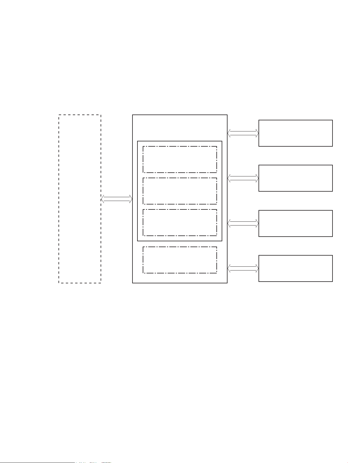
Basic operation
Engine-control system
Laser scanner system
Image-formation system
Pickup, feed and delivery system
Scanner system (M274 and M277 models only)
The printer routes all high-level processes through the formatter, which stores font information, processes
the print image, and communicates with the host computer.
The basic printer operation comprises the following systems:
●
Engine control system
●
Laser scanner system
●
Image-formation system
●
Pickup, feed, and delivery system
●
Integrated scanner system (M274 and M277 models only)
Figure 1-1 Basic operation
ENWW Basic operation 3
Page 24

Sequence of operation
The DC controller PCA controls the operating sequence, as described in the following table.
Table 1-1 Sequence of operation
Period Duration Description
Waiting From the time the power is turned on,
the door is closed, or when the printer
exits sleep mode until the printer is
ready for printing
Standby From the end of the waiting sequence,
the last rotation until the formatter
receives a print command, or until the
printer is turned o
Initial rotation From the time the formatter receives
a print command until the paper
enters the paper path
●
Heats the fuser lm in the fuser
●
Pressurizes the fuser pressure roller
●
Detects the toner cartridges
●
Separates all of the developer rollers from the photosensitive
drums
●
Rotates and stops each motor
●
Rotates and stops the main fan
●
Cleans the intermediate transfer belt (ITB) and secondary
transfer roller
●
Detects cable breakage on the thermistor
●
Detects any residual paper in the engine
●
The printer is in the Ready state
●
The printer enters sleep mode if the sleep command is received
from the formatter
●
The printer calibrates if it is time for an automatic calibration
●
Rotates each motor and the main fan
●
Activates the high-voltage power supply
Printing From the time the rst sheet of paper
enters the paper path until the last
sheet has passed through the fuser
Last rotation From the time the last sheet of paper
exits the fuser until the motors stop
rotating
●
Prepares the laser scanner unit
●
Warms the fuser to the correct temperature
●
Forms the image on the photosensitive drums
●
Transfers the toner to the paper
●
Fuses the toner image onto the paper
●
Moves the last printed sheet into the output bin
●
Stops each motor and the main fan
●
Stops the high-voltage power supply
●
Stops the laser scanner unit
●
Stops the fuser
●
Cleans the ITB and secondary transfer roller
●
If the DC controller receives another print command, the printer
enters the initial rotation period when the last rotation is
complete.
4 Chapter 1 Theory of operation ENWW
Page 25

Formatter-control system
The formatter is involved in the following procedures:
●
Controlling the sleep delay function
●
Receiving and processing print data from the various printer inputs
●
Monitoring control-panel functions and relaying printer status information (through the control panel
and the bidirectional input/output)
●
Developing and coordinating data placement and timing with the DC controller PCA
●
Storing font information
●
Communicating with the host computer through the bidirectional interface
The formatter receives a print job from the bidirectional interface and separates it into image information and
instructions that control the printing process. The DC controller PCA synchronizes the image-formation
system with the paper input and output systems, and then signals the formatter to send the print-image
data.
Sleep delay
When the printer is in sleep delay mode, the control-panel backlight is turned o, but the printer retains all
printer settings, downloaded fonts, and macros. The default setting is a 15-minute idle time. The setting can
be changed or turned o from the control panel menus.
The printer exits sleep delay mode and enters the warm-up cycle when any of the following occurs:
●
A print job, valid data, or a PML or PJL command is received at the serial port.
●
The control panel is touched.
●
A document is loaded in the document feeder or the scanner lid is opened.
●
A tray is opened.
TIP: Error messages override the sleep delay message. The printer enters sleep mode at the appropriate
time, but the error message continues to display.
Printer job language (PJL)
Printer job language (PJL) is an integral part of conguration, in addition to the standard printer command
language (PCL). With standard cabling, use PJL to perform a variety of functions.
●
Dynamic I/O switching. The printer can be congured with a host on each I/O by using dynamic I/O
switching. Even when the printer is oine, it can receive data from more than one I/O simultaneously,
until the I/O buer is full.
●
Context-sensitive switching. The printer can automatically recognize the personality (PS or PCL) of each
job and congure itself in that personality.
●
Isolation of print environment settings from one print job to the next. For example, if a print job is sent
to the printer in landscape mode, the subsequent print jobs are printed in landscape mode only if they
are formatted for it.
ENWW Formatter-control system 5
Page 26

Printer management language (PML)
The printer management language (PML) allows remote conguration and status monitoring through the I/O
ports.
Control panel
The formatter sends and receives printer status and command data to and from the control panel.
Walk-up USB (touchscreen models only)
This printer features printing from a USB ash drive. This printer supports printing the following types of les
from the USB ash drive:
●
.pdf
●
.jpg
●
.prn and .PRN
●
.cht and .CHT
●
.pxl
●
.pcl and .PCL
●
.ps and .PS
●
.doc and .docx
●
.ppt and .pptx
When a USB ash drive is inserted into the front of the printer, the control panel displays the USB Flash Drive
menu. The les present on the USB ash drive can be accessed from the control panel. Any les in a
supported format on the USB ash drive can be printed directly from the printer control panel. Pages also can
be scanned and saved to the USB ash drive from the control panel.
Wireless (wireless models only)
Wireless models contain a wireless card to enable 802.11b/g/n wireless communication.
Low end data model (LEDM)
The low-end data model (LEDM) provides one consistent data representation method and denes the
dynamic and capabilities tickets shared between clients and devices, as well as the access protocol, event,
security, and discovery methods.
Advanced control language (ACL) overview
The advanced control language (ACL) is a language that supports printer control and rmware downloads in
printers that support both PJL/PCL and host-based printing. Each sequence of ACL commands must be
preceded by a unied exit command (UEL) and an @PJL ENTER LANGUAGE=ACL command. The ACL sequence
is always followed by a UEL. Any number of commands can be placed between the UELs. The only exception to
these rules is the download command. If a rmware download is completed, the download command must be
the last command in the sequence. It will not be followed by a UEL.
6 Chapter 1 Theory of operation ENWW
Page 27

The rmware searches for the UEL sequence when parsing commands. However, while downloading binary
data such as host-based code or NVRAM data the rmware suspends UEL parsing. To handle hosts that
“disappear” during binary sequences, the rmware times out all ACL command sessions. If a timeout occurs
during a non-download command sequence, it is treated as the receipt of a UEL. If a timeout occurs during
rmware download, the printer resets.
Near eld communication (NFC) (wireless models only)
This printer supports near eld communication (NFC) capabilities. NFC enables an easy one-to-one HP
wireless direct print connection using a simple device-to-device touch. Mobile device users can quickly
connect to the printer and print documents and images from a mobile device, such as a smartphone or tablet,
by touching the device to the NFC icon on the printer.
CPU
The formatter incorporates an 800 MHz processor.
Input/output
The following sections discuss the input and output features of the printer.
USB
The printer includes a universal serial bus (USB) 2.0 connection.
USB hosts
The printer includes USB hosts for USB ash drive and wireless communication control.
10/100 networking
The printer includes a 10/100 network (ethernet) connection.
Fax (M277 models only)
The M277 models include a fax phone line connection.
Memory
If the printer encounters a problem when managing available memory, a clearable warning message displays
on the control panel.
Firmware
Memory on the formatter stores the rmware. A remote rmware upgrade process is used to overwrite and
upgrade the rmware.
Nonvolatile random access memory (NVRAM)
The printer uses nonvolatile memory (NVRAM) to store I/O and information about the print environment
conguration. The contents of NVRAM are retained when the printer is turned o or disconnected.
Flash memory
NOR: Stores microprocessor control programs and internal character sets (fonts).
ENWW Formatter-control system 7
Page 28

NAND: Stores fax memory (M277 models only) and driver installation software.
Random access memory (RAM)
The M252n model comes with 128 MB of memory installed. All other models come with 256 MB of memory
installed. The formatter has 256 MB NAND Flash.
HP Memory enhancement technology (MEt)
The HP Memory Enhancement technology (MEt) eectively doubles the standard memory through a variety of
font- and data-compression methods.
NOTE: The MEt is available only in PCL mode; it is not functional when printing in PS mode.
8 Chapter 1 Theory of operation ENWW
Page 29
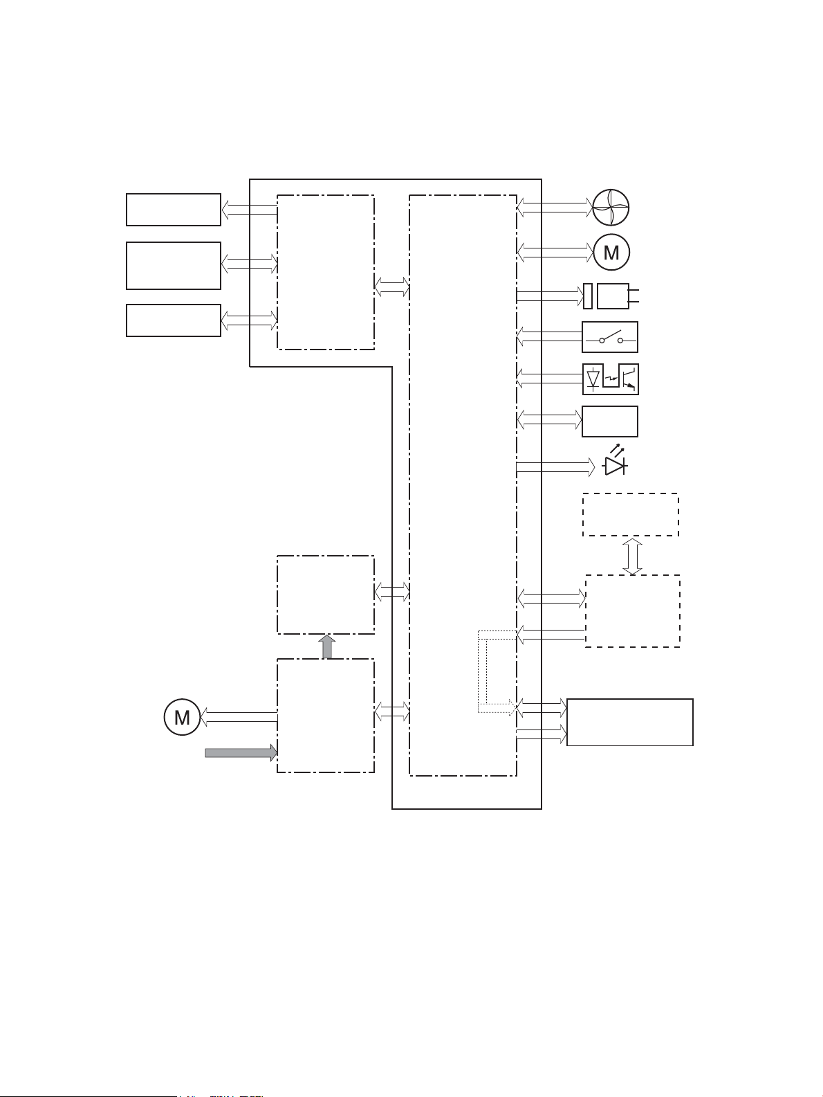
Engine-control system
Formatter
DC controller
Low-voltage power supply
Laser scanner system
Image-formation system
Pickup, feed and delivery
system
High-voltage power supply
Fuser control
Engine controller
Formatter-control system
Scanner system
(M274, M277 models only)
The engine-control system receives commands from the formatter and coordinates all the other systems.
The engine-control system contains the following components:
●
Engine control unit: DC controller and high-voltage power supply
●
Low-voltage power supply
●
Fuser control
Figure 1-2 Engine-control system
The formatter receives a print job from the bidirectional interface and separates it into image information and
instructions that control the printing process. The DC controller PCA synchronizes the image-formation
system with the paper input and output systems, and then signals the formatter to send the print-image
data.
ENWW Engine-control system 9
Page 30
Engine control unit (ECU)
ITB assembly
Secondary
transfer roller
Cartridge
(Y/M/C/K)
High-voltage
power supply
LED
Fan
Motor
Solenoid
Switch
Photointerrupter
Sensor
Formatter
Control panel
Laser scanner
assembly
AC input
Low-voltage
power supply
Fuser
Motor
DC controller
Engine control unit
The engine control unit includes the DC controller and the high-voltage power supply.
Figure 1-3 Engine control unit
DC controller
The DC controller PCA controls the operation of the printer and its components. The DC controller PCA starts
printer operation when the power is turned on and the power supply sends DC voltage to the DC controller
PCA. After the printer enters the standby sequence, the DC controller PCA sends out various signals to operate
motors, solenoids, and other electrical components based on the print command and image data that the
host computer sends.
10 Chapter 1 Theory of operation ENWW
Page 31

High-voltage power supply
Y
M
C
K
ITB
High-voltage power supply
Static charge
eliminator
T1 bias and
developing bias
circuit (YMC)
T2 bias circuit
ITB cleaning brush
bias circuit
T2 roller
Cartridge
DC controller
ITB cleaning brush
Engine controller
T1 bias and
developing bias
circuit (Bk)
Static charge
eliminator bias
circuit
The DC controller controls the high-voltage power supply to generate high-voltage biases. The high-voltage
power supply generates the high-voltage biases that are applied to the following components:
●
Primary charging roller (in the toner cartridges)
●
Developer roller (in the toner cartridges)
●
Primary transfer roller
●
Secondary transfer roller
●
ITB cleaning brush
●
Static charge eliminator
Figure 1-4 High-voltage power supply
Motors
The printer includes four motors that aect the paper-feed and image-formation processes.
Table 1-2 Printer motors
Component name Abbreviation Components driven
Main motor M701
ENWW Engine-control system 11
1
●
Photosensitive drum
●
Developer
●
Intermediate transfer belt (ITB)
Page 32

Table 1-2 Printer motors1 (continued)
Component name Abbreviation Components driven
Fuser motor M702
Pickup motor M703
Scanner motor M704
1
Because the integrated scanner assembly on the M274 and M277 models is a whole unit replacement, those motors are not included
on this list.
●
Pressure roller
●
Pressure/release of the pressure roller
●
Output roller
●
Duplex feed roller (duplex models only)
●
Pickup roller
●
Feed roller
●
Feed roller Registration roller
●
Duplex re-pickup roller (duplex models only)
●
Scanner mirror
The DC controller determines the following motor failures:
●
ITB motor start-up failure
●
ITB motor rotation failure
●
Developer alienation failure
Fans
Solenoids
The printer has one fan for preventing the printer from overheating and for cooling the delivered media.
Table
1-3 Printer fan
Component name Abbreviation Cooling area Type Speed
Main fan FM1
●
Toner cartridges
●
Low-voltage power supply area
Intake Full/Half
The DC controller determines the fan motor1 failure.
The printer has four solenoids. Solenoids are used for printer operation control.
1-4 Solenoids
Table
Component abbreviation Component name
SL711 Developer alienation solenoid
SL712 Pickup solenoid
SL713 Duplex re-pickup solenoid (duplex models only)
SL714 Duplex switchback solenoid (duplex models only)
12 Chapter 1 Theory of operation ENWW
Page 33

Switches
The printer has seven switches. Switches are used for printer operation control.
Table 1-5 Switches
Component abbreviation Component name
SW1 Developer home position detection switch
SW2 Fuser pressure release detection switch
SW3 Rear door switch, left
SW4 Front door switch
SW5 Priority slot media presence detection switch
SW6 Rear door switch, right (simplex models only)
SW601 Power switch
ENWW Engine-control system 13
Page 34

Sensors
The printer has 10 sensors. Sensors are used for remote detection of various functions during printer
operation.
Table 1-6 Sensors
Component abbreviation Component name
SR601 Media width sensor, right
SR602 Media width sensor, left
SR603 Priority slot top sensor
SR604 Registration sensor
SR606 Loop sensor (simplex models only)
SR607 Fuser delivery sensor
SR608 Output sensor (M252dw, M274 and M277 models only)
SR616 Loop sensor (duplex models only)
(NA) Registration density sensor
(NA) Environment sensor (measures temperature and humidity)
14 Chapter 1 Theory of operation ENWW
Page 35

Low-voltage power supply
Power switch
SW601
Low-voltage
power supply
AC input
DC controller
Fuse
FU101
Rectifying
circuit
+24V
generation
circuit
+3.3V
generation
circuit
Protection
circuit
+3.3VA
+24VA
PWSV
+3.3V
control circuit
Formatter, Contol panel
+3.3VC
+24V
control circuit
+3.3VB
+3.3VD
Front door switch
SW4
+3.3VA
+3.3VC
+24VB (Nebula only)
+24VB
REM24V
+24VB1
The low-voltage power supply converts AC power from the power receptacle into DC power to cover the DC
loads.
Figure 1-5 Low-voltage power supply
Overcurrent/overvoltage protection
The low-voltage power supply has a protective function against overcurrent and overvoltage conditions to
prevent failures in the power supply circuit. If an overcurrent or overvoltage event occurs, the system
automatically cuts o the output voltage.
Low-voltage power supply unit failure detection
If the DC power is not being supplied from the low-voltage power supply, the protective function might have
activated. In this case, turn o the power switch, and then disconnect the power cord. Do not connect the
power cord or turn the power switch on again until the root cause is found.
The DC controller determines a low-voltage power supply failure, stops 24V output and noties the formatter
when it detects that the 24V output is higher than the specied voltage.
ENWW Engine-control system 15
Page 36

Engine laser scanner system
Beam detect
sensor
Laser assembly
Scanner mirror
Scanner motor assembly
Photosensitive drum (K)
Photosensitive drum (C)
Photosensitive drum (M)
Photosensitive drum (Y)
DC controller
The formatter sends video signals to the DC controller, which controls the laser scanner. When the laser
scanner system receives those signals, it converts them to latent images on the photosensitive drum.
Figure 1-6 Laser scanner system
Laser failure detection
The optical unit failure detection sensor manages the laser scanner unit failure-detection functions. The DC
controller identies the laser scanner unit failure and noties the formatter if the laser scanner unit
encounters the following conditions:
●
Scanner motor start-up failure
●
Scanner motor rotational failure
16 Chapter 1 Theory of operation ENWW
Page 37

Image formation system
Latent image formation
Developing
Transfer
Fusing
Drum cleaning
Pickup
Registration
6. Separation
7. Fusing
Delivery
4. Primary transfer
2. Laser-beam exposure
3. Developing
8. Drum cleaning
1. Priminary charging
: Paper path
: Direction of drum rotation
: Functional block
: Step
5. Secondary transfer
YM C K
Image formation process
The image-formation system consists of 10 steps divided into six functional blocks.
Figure 1-7 Image-formation process
Step 1: Primary charging
Table 1-7 Image formation process
Functional block Steps Description
Latent image formation 1. Primary charging
2. Laser-beam exposure
Development 3. Development Toner adheres to the electrostatic latent image on the
Transfer 4. Primary transfer
5. Secondary transfer
Fusing 7. Fusing The toner fuses to the paper to make a permanent
Drum cleaning 8. Drum cleaning Residual toner is removed from the photosensitive
6. Separation
An invisible latent image forms on the surface of the
photosensitive drums.
photosensitive drums.
The toner image transfers to the ITB and later to the
paper.
image.
drums.
The primary-charging roller contacts the photosensitive drum and charges the drum with negative potential.
ENWW Image formation system 17
Page 38

Figure 1-8 Primary charging
Photosensitive drum
Primary charging roller
Primary charging bias
18 Chapter 1 Theory of operation ENWW
Page 39

Step 2: Laser-beam exposure
Photosensitive drum
Laser beam
Photosensitive drum
Primary charging roller
Primary charging bias
The laser beam strikes the surface of the photosensitive drum in the areas where the image will form. The
negative charge neutralizes in those areas, which are then ready to accept toner.
Figure 1-9 Laser-beam exposure
Step 3: Development
Toner acquires a negative charge as the developing cylinder contacts the developing blade. Because the
negatively charged surface of the photosensitive drums have been neutralized where they have been struck
by the laser beam, the toner adheres to those areas on the drums. The latent image becomes visible on the
surface of each drum.
Figure 1-10 Development
ENWW Image formation system 19
Page 40

Step 4: Primary transfer
Photosensitive
drum
Primary transfer
roller
ITB
Primary transfer bias
ITB
Paper
Secondary transfer
roller
Secondary transfer bias
The positively charged primary-transfer rollers contact the ITB, giving the ITB a positive charge. The ITB
attracts the negatively charged toner from the surface of each photosensitive drum, and the complete toner
image transfers onto the ITB.
Figure 1-11 Primary transfer
Step 5: Secondary transfer
The paper acquires a positive charge from the secondary-transfer roller, and so it attracts the negatively
charged toner from the surface of the ITB. The complete toner image transfers onto the paper.
Figure 1-12 Secondary transfer
20 Chapter 1 Theory of operation ENWW
Page 41

Step 6: Separation
Static chargeeliminator bias
ITB
Paper
Secondary transfer
roller
Static charge eliminator
Paper
Fuser film
Fuser heater
Pressure roller
The stiness of the paper causes it to separate from the ITB as the ITB bends. The static-charge eliminator
removes excess charge from the paper to make sure that the toner fuses correctly.
Figure 1-13 Separation
Step 7: Fusing
Step 8: Drum cleaning
To create the permanent image, the paper passes through heated, pressurized rollers to melt the toner onto
the page.
Figure 1-14 Fusing
The cleaning blade scrapes the residual toner o the surface of the photosensitive drum, and toner is
deposited in the toner collection box in the cartridge.
ENWW Image formation system 21
Page 42

Figure 1-15 Drum cleaning
Cleaning blade
Residual toner collection box
Photosensitive
drum
22 Chapter 1 Theory of operation ENWW
Page 43

Toner cartridges
DC controller
Memory chip
Photosensitive drum
Developer
Primary charging
roller
Developer roller
Cartridge
SW1
M701
The printer has four toner cartridges, one for each color: cyan, magenta, yellow, and black.
Design
Each toner cartridge is lled with toner and consists of the following components:
●
Photosensitive drum
●
Developer
●
Primary-charging roller
●
Memory chip
The DC controller rotates the drum motor to drive the photosensitive drum, developing roller, and the
primary-charging roller.
Figure 1-16 Toner cartridge system
ENWW Image formation system 23
Page 44

Memory chip
The memory chip is non-volatile memory that stores information about the usage of the toner cartridge and
helps protect the customer from counterfeit cartridges. This chip is also used to detect the presence of a
cartridge within the printer or when a cartridge is installed in the wrong slot. The printer reads and writes the
data in the memory chip.
HP Cartridges with JetIntelligence
HP Cartridges with JetIntelligence supports two features for managing toner cartridges.
●
The HP Cartridge Policy feature allows customers to specify the use of only genuine HP toner cartridges
in the printer.
●
The anti-theft feature enables locking a cartridge to a specic printer or eet of printers.
HP Cartridge Policy
The genuine HP Cartridge Policy feature allows a customer to specify that only genuine HP supplies can be
used in a printer. If anything but a genuine HP supply is installed, the printer will not print. This feature is
disabled by default, and can be enabled or disabled from the control panel, the HP Embedded Web Server
(EWS), or HP Web Jetadmin.
If a genuine HP cartridge has passed the low state and is installed in a printer that has this feature enabled,
the printer will display an Unauthorized Cartridge message on the control panel and will not print.
If a non-HP toner cartridge is used in a printer with this feature enabled, the message Unauthorized
Cartridge appears on the control-panel display and the printer will not print.
NOTE: If a customer suspects they have a counterfeit cartridge, they should report it by going to
www.hp.com/go/anticounterfeit and selecting Report now.
Anti-theft or cartridge protection
The toner cartridge anti-theft feature allows a customer to congure the printer to automatically lock toner
cartridges to a specic printer or eet of printers when they are installed. A locked toner cartridge will work
only in the specied printer or eet of printers. This feature prevents toner cartridges from being stolen and
used in another printer, or from being moved from an authorized printer to an unauthorized printer. This
feature is disabled by default. Cartridge protection to a single printer can be enabled or disabled from the
control panel or the HP Embedded Web Server (EWS). Cartridge protection for a printer eet can be enabled
only by using HP Web Jetadmin.
When the anti-theft feature is enabled, the toner cartridge in a printer will only work in the specied printer or
eet of printers. If a locked toner cartridge is moved to another printer, the cartridge will not print and the
message Protected Cartridge appears on the control-panel display.
NOTE: When a toner cartridge is locked to a specic printer or eet of printers, it cannot be unlocked. This is
a permanent operation.
Intermediate transfer belt (ITB) assembly
The ITB assembly accepts the toner images from the photosensitive drums and transfers the completed
image to the paper. The ITB unit has these main components:
24 Chapter 1 Theory of operation ENWW
Page 45

●
Main motor
DC controller
M701
ITB
Primary transfer roller
ITB drive roller
ITB
●
ITB drive roller
●
Primary transfer roller
Figure 1-17 ITB assembly
The main motor drives the ITB drive roller, which rotates the ITB. The ITB motion causes the primary transfer
rollers to rotate.
ENWW Image formation system 25
Page 46

Engine pickup, feed, and delivery system
Pickup-and-feed block
Duplex paper path
Simplex paper path
Duplex block
Fuser-and-delivery block
The pickup, feed, and delivery system uses a series of rollers to move the paper through the printer. The
pickup, feed and delivery system consists of following components:
●
Pickup-and-feed block: From each pickup source to the fuser inlet
●
Fuser-and-delivery block: From the fuser to the delivery destination
●
Duplex block (duplex models only): From the duplex switch back unit to duplex re-pickup unit
Figure 1-18 Paper path
26 Chapter 1 Theory of operation ENWW
Page 47

Figure 1-19 Switches and sensors for the pickup, feed, and delivery system
SW5
SR603
SR601
SR602
SR608
SR607
SR606
SR616
SR604
Table 1-8 Switches and sensors for the pickup, feed, and delivery system
Abbreviation Component
SR601 Media width sensor, right
SR602 Media width sensor, left
SR603 Priority slot top of page (TOP) sensor
SR604 Registration sensor
SR606 Loop sensor (simplex models only)
SR607 Fuser delivery sensor
SR608 Output sensor (M252dw, M274 and M277 models only)
SR616 Loop sensor (duplex models only)
SW5 Priority slot media-presence switch
ENWW Engine pickup, feed, and delivery system 27
Page 48

Figure 1-20 Motors and solenoids for the pickup, feed, and delivery system
M703
M701
M702
SL713
SL712
SL714
Table 1-9 Motors and solenoids for the pickup, feed, and delivery system
Abbreviation Component
M701 Main motor
M702 Fuser motor
M703 Pickup motor
SL712 Cassette pickup solenoid
SL713 Duplex re-pickup solenoid (duplex models only)
SL714 Duplex switchback solenoid (duplex models only)
28 Chapter 1 Theory of operation ENWW
Page 49

Priority input slot pickup
The priority input slot paper-presence sensor detects whether paper is in the tray. If no paper is present, the
DC controller noties the formatter. The print operation is not performed until paper is in the slot.
The sequence of steps for the priority input slot pickup operation is as follows:
1. After receiving a print command from the formatter, the DC controller reverses the pickup motor, which
causes the priority input slot separation roller to rotate.
2. The DC controller turns on the priority input slot pickup solenoid, causing the pickup roller to rotate, and
paper is picked from the stack.
3. The priority input slot separation roller isolates a single sheet of paper in case more than one sheet was
picked. The single sheet of paper is fed into the printer. This mechanism is the same as for the Tray 2
cassette pickup operation.
ENWW Engine pickup, feed, and delivery system 29
Page 50

Cassette pickup
M703
M701
M702
SL713
SL712
SL714
The sequence of steps for the cassette tray pickup operation is the following:
After receiving a print command from the formatter, the DC controller rotates the pickup motor, which causes
the lifting mechanism to lift the paper stack against the pick roller, at which time the cassette pickup roller,
cassette feed roller, and cassette separation roller rotate to feed the sheet.
Duplexing unit
The duplexing unit reverses the paper and feeds it through the paper path to print the second side. The
duplexing unit consists of the following components:
●
Duplexing-reverse unit: Located on top of the printer
●
Duplexing-feed unit: Located on the right side
The DC controller controls the operational sequence of the duplex block. The DC controller drives each load,
such as motors, solenoid, and clutch, depending on the duplex-reverse unit and duplex-feed unit controls.
Figure 1-21 Duplexing unit controls
30 Chapter 1 Theory of operation ENWW
Page 51

Duplex reverse and duplex feed control
The duplexing reverse procedure pulls the paper into the duplexing unit after it exits the fuser. The duplexing
feed procedure moves the paper through the duplexer so it can enter the printer paper path to print the
second side of the page.
1. After the rst side has printed, the duplexing apper solenoid opens, which creates a paper path into the
duplexing-reverse unit.
2. After the paper has fully entered the duplexing-reverse unit, the duplexing-reverse motor reverses and
directs the paper into the duplexing-feed unit.
3. The duplexing re-pickup motor and duplexing feed motor move the paper into the duplexing repickup
unit.
4. To align the paper with the toner image on the ITB, the duplexing re-pickup motor stops and the paper
pauses.
5. The paper re-enters the paper path, and the second side prints.
Duplex pickup operation
The printer has the following two duplex-media-feed modes depending on the paper sizes:
●
One-sheet mode: Prints one sheet that is printed on two sides in one duplex print operation
●
Two-sheet mode: Prints two sheets that are printed on two sides in one duplex print operation
ENWW Engine pickup, feed, and delivery system 31
Page 52

Jam detection
The printer uses the following sensors to detect the presence of media and to check whether media is being
fed correctly or has jammed:
●
Priority slot top-of-page (TOP) sensor—SR603
●
Media width sensor, right—SR601
●
Media width sensor, left—SR602
●
Registration sensor—SR604
●
Loop sensor—SR606 (simplex models) or SR616 (duplex models)
●
Fuser delivery sensor—SR607
●
Output sensor (M252dw, M274 and M277 models)—SR608
The printer detects the following jams:
●
No pick jam 1
●
No pick jam 2
●
Pickup stay jam 1
●
Fuser delivery delay jam 1
●
Fuser delivery stay jam 1
●
Residual paper jam 1
●
Residual paper jam 2
●
Residual paper jam 3
●
Residual paper jam 4
●
Door open jam 1
●
Fuser wrapping jam 1
●
Duplex re-pickup jam 1 (simplex models)
●
Delivery delay jam 1 (M252dw, M274 and M277 models)
●
Delivery stay jam 1 (M252dw, M274 and M277 models)
32 Chapter 1 Theory of operation ENWW
Page 53

Scanning and image capture system
The atbed image scanner captures an electronic image of the document on the glass. The scanner does this
by illuminating the document with LEDs (red, green, and blue) and capturing the image in the image sensor to
create an electronic format of the document. The atbed scanner consists of three main elements.
●
CIS scanner
The CIS (contact image sensor) scanner captures an image using the printer's optical path. Red, green,
and blue LEDs sequentially illuminate a small strip of the document (often called a raster line), and the
optical system captures each color in a single row of CCD sensors that cover the entire page width.
Because only one color is captured for each line per exposure, the three colors are recombined
electronically to create the full color image. For monochromatic scans or copies, all three LEDs are
illuminated to create a white light for the scan so the raster line can be captured in one exposure.
●
Mechanical drive system
The drive system moves the CIS scanner along the document length to create the image. In this printer,
the drive system consists of a small DC motor with an optical encoder, a drive belt, and a guide rod. The
speed of the drive system is proportional to the scan resolution (300 ppi is much faster than 1200 ppi)
and also proportional to the type of scan (color scans are slower than monochromatic scans).
●
Image processing system (formatter)
The formatter processes the scanner data into either a copy or a scan to the computer. For copies, the
image data is sent directly to the printer without being transmitted to the computer. Depending on user
selections for the copy settings, the formatter enhances the scanner data signicantly before sending it
to the printer. Image data is captured at 300 ppi for copies and is user selectable for scans to the
computer. Each pixel is represented by 8 bits for each of the three colors (256 levels for each color), for a
total of 24 bits per pixel (24-bit color).
ENWW Scanning and image capture system 33
Page 54

Automatic document feeder (ADF) system
ADF simplex operation
The ADF will not function when the ADF cover is open. The paper path is incomplete if the ADF cover is lifted
from the glass.
When the printer duplexes from the ADF, the paper moves through one time, because the ADF has a CIS
scanner for side two which is scanned simultaneously with side one.
The standard operation of the ADF consists of the standby (paper loading) mode, pick, feed, and lift steps:
●
Standby (paper-loading) mode
In standby mode, the lift plate is in the down position. When a document is loaded into the input tray,
the paper-present sensor detects its presence.
When a copy/scan is initiated, the ADF motor engages the gear train and raises the lift plate until the
document makes contact with the pick roller. The ADF then begins the pick, feed, and home sequence.
●
Pick
The pick roller rotates and moves one or more sheets forward into the ADF where the sheets engage
with the separation roller. The separation roller contacts the ADF separation pad, which separates
multiple sheets into single sheets.
●
Feed
The single sheet continues through the ADF paper path (aided by the pre-scan rollers) until the leading
edge of the page activates the top-of-form sensor. Activation of this sensor initiates the scan process,
and the scanner acquires the image as the document moves over the ADF glass. The post-scan rollers
then eject the sheet into the output area. The pick and feed steps are repeated as long as paper is
detected by the paper-present sensor.
●
Home
When the form sensor detects the trailing edge of the last page, the last sheet is ejected and the motor
turns on a sequence that rests the separation oor back down in standby mode, which allows it to detect
when more media is loaded.
Note that the ADF will not function when the ADF door is open.
34 Chapter 1 Theory of operation ENWW
Page 55

Fax functions and operation (fax models only)
The following sections describe the printer fax capabilities.
Computer and network security features
The printer can send and receive fax data over telephone lines that conform to public switch telephone
network (PSTN) standards. The secure fax protocols make it impossible for computer viruses to be
transferred from the telephone line to a computer or network.
The following printer features prevent virus transmission:
●
No direct connection exists between the fax line and any devices that are connected to the USB or
Ethernet ports.
●
The internal rmware cannot be modied through the fax connection.
●
All fax communications go through the fax subsystem, which does not use Internet data-exchange
protocols.
PSTN operation
The PSTN operates through a central oce (CO) that generates a constant voltage on the TIP and RING wires
(48 V, usually). A device goes on-hook by connecting impedance (such as 600 ohms for the U.S.) across the
TIP and RING so that a line current can ow. The CO can detect this current and can send impulses like dial
tones. The printer generates more signaling tones, such as dialing digits, to tell the CO how to connect the
call. The printer can also detect tones, such as a busy tone from the CO, that tell it how to behave.
When the call is nally connected, the CO behaves like a piece of wire connecting the sender and receiver. This
is the period during which all of the fax signaling and data transfer occurs. When a call is completed, the
circuit opens again and the line-current ow ceases, removing the CO connection from both the sender and
the receiver.
On most phone systems, the TIP and RING signals appear on pins 3 and 4 of the RJ-11 modular jack (the one
on the fax card, as dened in the common 6 wire RJ standard). These two signals do not have to be polarized
because all of the equipment works with either TIP or RING on one pin and the other signal on the other pin.
This means that cables of either polarity can interconnect and still work.
These basic functions of PSTN operation are assumed in the design of the fax subsystem. The printer
generates and detects the signaling tones, currents, and data signals that are required to transmit and
receive faxes using the PSTN.
Receive faxes when you hear fax tones
In general, incoming faxes to the printer are automatically received. However, if other devices are connected
to the same phone line, the printer might not be set to answer automatically.
If the printer is connected to a phone line that receives both fax and phone calls, and you hear fax tones when
you answer the extension phone, receive the fax in one of two ways:
●
If you are near the printer, press Start Fax on the control panel.
●
Press 1-2-3 in sequence on the extension phone keypad, listen for fax transmission sounds, and then
hang up.
ENWW Fax functions and operation (fax models only) 35
Page 56

NOTE: In order for the 1-2-3 sequence to work, the extension phone setting must be set to On in the
Fax Setup menu.
Distinctive ring function
Distinctive ring is a service that a telephone company provides. The distinctive ring service allows three phone
numbers to be assigned to one phone line. Each phone number has a distinctive ring. The rst phone number
has a single ring, the second phone number has a double ring, and the third phone number has a triple ring.
NOTE: The printer has not been tested with all of the distinctive-ring services that telephone companies
provide in all countries/regions. HP does not guarantee that the distinctive-ring function will operate correctly
in all countries/regions. Contact the local phone service provider for assistance.
Set up the distinctive ring function
1. Open the Setup menu.
2. Open the Fax Menu menu.
3. Select the Basic Setup menu.
4. Select the Distinctive Ring setting.
5. Use the arrow buttons to select one of the following options:
●
All Rings (default setting)
●
Single
●
Double
●
Triple
●
Double and Triple
Fax by using voice over IP (VOIP) services
Voice over IP (VoIP) services provide normal telephone service, including long distance service through a
broadband Internet connection. These services use packets to break up the voice signal on a telephone line
and transmit it digitally to the receiver, where the packets are reassembled. The VoIP services are often not
compatible with fax machines. The VoIP provider must state that the service supports fax over IP services.
Because the installation process varies, the VoIP service provider will have to assist in installing the printer
fax component.
Although a fax might work on a VoIP network, it can fail when the following events occur:
●
Internet trac becomes heavy and packets are lost.
●
Latency (the time it takes for a packet to travel from its point of origin to its point of destination)
becomes excessive.
If you experience problems using the fax feature on a VoIP network, make sure that all of the printer cables
and settings are correct. Conguring the Fax Speed setting to Medium(V.17) or Slow(V.29) can also improve
your ability to send a fax over a VoIP network.
If you continue to have problems faxing, contact your VoIP provider.
36 Chapter 1 Theory of operation ENWW
Page 57

The fax subsystem
The formatter, fax card, rmware, and software all contribute to the fax functionality. The designs of the
formatter and fax card, along with parameters in the rmware, determine the majority of the regulatory
requirements for telephony on the printer.
The fax subsystem is designed to support V.34 fax transmission, low speeds (such as V.17 fax), and older fax
machines.
Fax card in the fax subsystem
Two versions of the fax card are used in the printer. One is used in the North American, South American, and
Asian countries/regions. The other is used primarily in European countries/regions.
The fax card contains the modem chipset (DSP and CODEC) that controls the basic fax functions of tone
generation and detection, along with channel control for fax transmissions. The CODEC and its associated
circuitry act as the third-generation silicon data access arrangement (DAA) to comply with worldwide
regulatory requirements.
The only dierence between the two versions is that each version is compliant with the 2/4-wire phone jack
system from the respective country/region.
Safety isolation
The most important function of the fax card is the safety isolation between the high-voltage, transient-prone
environment of the telephone network (TNV [telephone network voltage]) and the low-voltage analog and
digital circuitry of the formatter (SELV [secondary extra-low voltage]). This safety isolation provides both
customer safety and printer reliability in the telecom environment.
Any signals that cross the isolation barrier do so magnetically. The breakdown voltage rating of barriercritical components is greater than 5 kV.
Safety-protection circuitry
In addition to the safety barrier, the fax card protects against over-voltage and over-current events.
Telephone over-voltage events can be either dierential mode or common mode. The event can be transient
in nature (a lightning-induced surge or ESD) or continuous (a power line crossed with a phone line). The fax
card protection circuitry provides margin against combinations of over-voltage and overcurrent events.
Common mode protection is provided by the selection of high-voltage-barrier critical components
(transformer and relay). The safety barrier of the fax card PCB traces and the clearance between the fax card
and surrounding components also contribute to common mode protection.
A voltage suppressor (a crowbar-type thyristor) provides dierential protection. This device becomes low
impedance at approximately 300 V dierential, and crowbars to a low voltage. A series thermal switch works
in conjunction with the crowbar for continuous telephone line events, such as crossed power lines.
All communications cross the isolation barrier magnetically. The breakdown voltage rating of barrier-critical
components is greater than 5 kV.
Data path
TIP and RING are the two-wire paths for all signals from the telephone network. All signaling and data
information comes across them, including fax tones and fax data.
ENWW Fax functions and operation (fax models only) 37
Page 58

The telephone network uses DC current to determine the hook state of the telephone, so line current must be
present during a call. The silicon DAA provides a DC holding circuit to keep the line current constant during a
fax call.
The silicon DAA converts the analog signal to a digital signal for DSP processing, and also converts the digital
signal to an analog signal for transmitting data through a telephone line.
The magnetically coupled signals that cross the isolation barrier go through either a transformer or a relay.
The DSP in the fax card communicates with the ASIC in the formatter using the high-speed serial interface.
Hook state
Another magnetically coupled signal is the control signal that disconnects the downstream telephone devices
(such as a phone or answering machine). A control signal originating on the DSP can change the relay state,
causing the auxiliary jack (downstream jack) to be disconnected from the telephone circuit.
The printer takes control of calls that it recognizes as fax calls. If the printer does not directly pick up the call,
it monitors incoming calls for the fax tone or for the user to direct it to receive a fax. This idle mode is also
called eavesdropping. This mode is active when the printer is on-hook but current exists in the downstream
phone line because another device is o-hook. During eavesdropping, the receive circuit is enabled but has a
dierent gain from the current that is generated during normal fax transmissions.
The printer does not take control of the line unless it detects a fax tone or the user causes it to connect
manually. This feature allows the user to make voice calls from a phone that is connected to the printer
without being cut o if a fax is not being received.
Downstream device detection
The line voltage monitoring module of the silicon DAA can detect the line state as well as the downstream
device. It tells DSP via DIB that an active device (telephone, modem, or answering machine) is connected to
the auxiliary port on the printer (the right side of the dual RJ-11 jack). The DSP uses the signal to ensure that
the printer does not go o-hook (and disconnects a downstream call) until it has been authorized to do so (by
a manual fax start or the detection of the appropriate tones).
Hook switch control
In the silicon DAA the CODEC controls the hook switch directly. The CODEC is activated when it receives
commands from the DSP. When the circuit is drawing DC current from the central oce it is considered o-
hook. When no DC current ows the state is considered on-hook.
Ring detect
Ring detect is performed by the line voltage monitoring module of the silicon DAA, and is a combination of
voltage levels and cadence (time on and time o). Both must be present to detect a valid ring. The CODEC
works with DSP as well as the rmware to determine if an incoming signal is an answerable ring.
Line current control
The DC current from the CO needs to have a path to ow from TIP to RING. The DC impedance emulation line
modulator and DC terminations modules in the silicon DAA act as a DC holding circuit, and work with the
rmware to achieve the voltage-current characteristic between TIP and RING. The impedance (the currentvoltage characteristic) changes corresponding to certain special events, such as pulse dialing or when the
printer goes on-hook.
38 Chapter 1 Theory of operation ENWW
Page 59

Billing or metering tone lters
Switzerland and Germany provide high-frequency AC signals on the phone line in order to bill customers.
A lter in a special fax cable (for certain countries/regions), can lter these signals. Because these billing
signals are not used in the U.S., these lters are not present in the U.S. fax cable.
To obtain a special fax cable, contact your local telephone service provider.
Fax page storage in ash memory
Fax pages are the electronic images of the document page. They can be created in any of three ways: scanned
to be sent to another fax machine, generated to be sent by the computer, or received from a fax machine to
be printed.
The printer stores all fax pages in ash memory automatically. After these pages are written into ash
memory, they are stored until the pages are sent to another fax machine, printed on the printer, transmitted
to the computer, or erased by the user.
These pages are stored in ash memory, which is the nonvolatile memory that can be repeatedly read from,
written to, and erased. The printer has 8 MB of ash memory, of which 7.5 MB is available for fax storage. The
remaining 0.5 MB is used for the le system and reclamation. Adding RAM does not aect the fax page
storage because the printer does not use RAM for storing fax pages.
Stored fax pages
The user can reprint stored fax receive pages in case of errors. For a fax send, the printer will resend the fax in
case of errors. The printer will resend stored fax pages after a busy signal, communication error, no answer,
or power failure. Other fax devices store fax pages in either normal RAM or shortterm RAM. Normal RAM
immediately loses its data when power is lost, while short-term RAM loses its data about 60 minutes after
power failure. Flash memory maintains its data for years without any applied power.
Advantages of ash memory storage
Fax pages that are stored in ash memory are persistent. They are not lost as a result of a power failure, no
matter how long the power is o. Users can reprint faxes in case the print cartridge runs out of toner or the
printer experiences other errors while printing faxes.
The printer also has scan-ahead functionality that makes use of ash memory. Scan-ahead automatically
scans pages into ash memory before a fax job is sent. This allows the sender to pick up the original
document immediately after it is scanned, eliminating the need to wait until the fax transmission is complete.
Because fax pages are stored in ash memory rather than RAM, more RAM is available to handle larger and
more complicated copy and print jobs.
ENWW Fax functions and operation (fax models only) 39
Page 60

40 Chapter 1 Theory of operation ENWW
Page 61

2 Solve problems
●
Troubleshooting process
●
Tools for troubleshooting
●
Solve image quality problems
●
Clean the printer
●
Solve paper-handling problems
●
Prevent paper jams
●
Clear paper jams
●
Solve performance problems
●
Solve connectivity problems
●
Service mode functions
●
Solve fax problems (fax models only)
●
Solve email problems
●
Update the rmware
ENWW 41
Page 62

Troubleshooting process
Solve problems checklist
If the printer is not correctly functioning, complete the steps (in the order given) in the following checklist. If
the printer fails a checklist step, follow the corresponding troubleshooting suggestions for that step. If a
checklist step resolves the problem, skip the remaining checklist items.
1. Make sure that the printer is set up correctly.
a. Press the power button to turn on the printer or to deactivate the Auto-O mode.
b. Check the power-cable connections.
c. Make sure that the line voltage is correct for the printer power conguration. See the label that is
on the printer for voltage requirements. If you are using a power strip and its voltage is not within
specications, plug the printer directly into the wall. If it is already plugged into the wall, try a
dierent outlet.
2. Check the cable connections.
a. Check the cable connection between the printer and the computer. Make sure that the connection is
secure.
b. Make sure that the cable itself is not faulty, by using a dierent cable if possible.
c. Check the network connection: Make sure that the network light is lit. The network light is next to
the network port on the back of the printer.
If the printer remains unable to connect to the network, uninstall and then reinstall the printer. If
the error persists, contact a network administrator.
3. Check to see if any messages appear on the control panel.
4. Make sure that the paper you are using meets specications.
5. Make sure that the paper is loaded correctly in the input tray.
6. Make sure that the printer software is installed correctly.
7. Verify that you have installed the printer driver for this printer, and that you are selecting this printer
from the list of available printers.
8. Print a conguration page.
a. 2-line control panels: On the printer control panel, press the OK button.
Touchscreen control panels: From the Home screen on the printer control panel, touch the Setup
button.
b. Open the Reports menu.
c. Select Conguration Report.
42 Chapter 2 Solve problems ENWW
Page 63

After printing the conguration page, check the following:
a. If the page does not print, verify that the input tray contains paper and that the paper is properly
loaded.
b. Make sure that each toner cartridge is installed correctly.
c. If the page jams in the printer, clear the jam.
d. If the print quality is unacceptable, complete the following steps:
●
●
9. Print a small document from a dierent program that has printed in the past. If this solution works, then
the problem is with the program you are using. If this solution does not work (the document does not
print), complete these steps:
a. Try printing the job from another computer that has the printer software installed.
b. Check the cable connection. Direct the printer to the correct port, or reinstall the software,
selecting the connection type you are using.
Print the menu map
To more easily navigate individual settings, print a report of the complete printer menus.
Verify that the print settings are correct for the paper you are using.
Solve print-quality problems.
1. 2-line control panels: On the printer control panel, press the OK button.
Touchscreen control panels: From the Home screen on the printer control panel, touch the Setup
button.
2. Open the Reports menu.
3. Select Menu Structure.
Print a conguration page
Print a conguration page to test the printer.
1. 2-line control panels: On the printer control panel, press the OK button.
Touchscreen control panels: From the Home screen on the printer control panel, touch the Setup
button.
2. Open the Reports menu.
3. Select Conguration Report.
ENWW Troubleshooting process 43
Page 64

Print the service page (includes the event log)
Printing the service page provides a list of printer settings that might be helpful in the troubleshooting
process, as well as the event log, which stores the last 10 error events that the printer experienced.
1. 2-line control panels: On the printer control panel, press the OK button.
Touchscreen control panels: From the Home screen on the printer control panel, touch the Setup
button.
2. Open the Reports menu.
3. Select the Service Page option to print the report.
The event log is located in the lower right-hand corner of the service page.
Determine the problem source
When the printer malfunctions or encounters an unexpected situation, the printer control panel alerts the
user to the situation. This section contains a pre-troubleshooting checklist to lter out many possible causes
of the problem. Use the troubleshooting owchart to help diagnose the root cause of the problem. The
remainder of this chapter provides steps for correcting problems.
●
Use the troubleshooting owchart to pinpoint the root cause of hardware malfunctions. The owchart
provides guides to the sections of this chapter that contain steps to correct the malfunction.
Before beginning any troubleshooting procedure, check the following issues:
●
Are supply items within their rated life?
●
Does the conguration page reveal any conguration errors?
NOTE: The customer is responsible for checking supplies and for using supplies that are in good condition.
Troubleshooting owchart
This owchart highlights the general processes to follow to quickly isolate and solve printer hardware
problems.
Each row depicts a major troubleshooting step. Follow a “yes” answer to a question to proceed to the next
major step. A “no” answer indicates that more testing is needed. Go to the appropriate section in this chapter,
and follow the instructions there. After completing the instructions, go to the next major step in this
troubleshooting owchart.
Table
2-1 Troubleshooting owchart
1
Power on
2
Control panel
messages
Is the printer on and does a readable message
display?
Yes
Does the message Ready display on the control
panel?
Yes
Follow the power-on troubleshooting checks.
After the control panel display is functional, see step 2.
No
After the errors have been corrected, go to step 3.
No
44 Chapter 2 Solve problems ENWW
Page 65

Table 2-1 Troubleshooting owchart (continued)
3
Event log
4
Information pages
5
Print quality
6
Interface
Print the service page to view the event log to
see the history of errors with this printer.
Does the service page print?
Yes
Open the Reports menu and print the
conguration page to verify that all the
accessories are installed.
Are all the accessories installed?
Yes
Does the print quality meet the customer's
requirements?
Yes
Can the customer print successfully from the
host computer?
Yes. This is the end of
the troubleshooting
process.
No
No
No
No
If the service page does not print, check for error messages.
If paper jams inside the printer, see the jams section of this manual.
If error messages display on the control panel when trying to print a
service page, see the control panel message section of this manual.
After successfully printing and evaluating the event log, see step 4.
If accessories that are installed are not listed on the conguration
page, remove the accessory and reinstall it.
After evaluating the conguration pages, see step 5.
Compare any print defects with the repetitive defect ruler in this
manual.
After the print quality is acceptable, see step 6.
Verify that all I/O cables are connected correctly and that a valid
IP address is listed on the HP Jetdirect conguration page.
If error messages display on the control panel when trying to print an
event log, see the control-panel message section of this manual.
When the customer can print from the host computer, this is the end of
the troubleshooting process.
Power subsystem
Power-on checks
The basic printer functions should start up when the printer is connected into an electrical outlet and the
power switch is pushed to the on position. If the printer does not start, use the information in this section to
isolate and solve the problem.
If the control panel display remains blank, random patterns display, or asterisks remain on the control panel
display, perform power-on checks to nd the cause of the problem.
Power-on troubleshooting overview
During normal operation, a cooling fan begins to spin briey after the printer power is turned on. Place a hand
over the fan intake vents located on the right-side cover. When the fan is correctly operating, air passing into
the printer is felt. Lean close to the printer to hear the fan operating. If the fan is operating, the dc side of the
power supply is functioning.
After the fan is operating, the main motor turns on (unless the top cover is open, a jam condition is sensed, or
the paper-path sensors are damaged). Visually and audibly determine that the main motor is turned on.
If the fan and main motor are operating correctly, the next troubleshooting step is to isolate print engine,
formatter, and control panel problems. Perform an engine test. If the formatter is damaged, it might interfere
with the engine test. If the engine-test page does not print, try removing the formatter, and then performing
the engine test again. If the engine test is then successful, the problem is almost certainly with the formatter,
the control panel, or the cable that connects them.
ENWW Troubleshooting process 45
Page 66

Perform an engine test
▲
With the printer on and in the Ready state, open and then close the front door four times (for a simplex
print out on both simplex and duplex models) or ve times (for a duplex print on duplex models). The
printer prints the engine test page.
Figure 2-1 Engine test page
Troubleshooting power on problems
1. Verify that power is available to the printer. If the printer is plugged into a surge protector or
uninterruptible power supply (UPS), remove it, and then plug the printer directly into a known operating
wall receptacle (make sure that the wall receptacle provides the correct voltage and current for the
printer).
Unplug any other devices on the same circuit that the printer is using.
2. Try another known operating wall receptacle and a dierent power cord.
3. Listen for startup noises (fans and motors) and illuminated lights on the control panel.
NOTE: Operational fans, motors, and control-panel lights indicate the following:
●
AC power is present at the printer.
●
The low-voltage power supply (LVPS) is providing either or both 24 Vdc and 5 Vdc voltages.
●
The DC controller microprocessor is functioning.
4. If startup noises are not heard, check the following:
a. Turn the printer o, and then remove the formatter.
b. Turn the printer on, and then listen for startup noises. If normal startup noises are heard, go to
step 5.
NOTE: The control panel will be blank with the formatter removed.
c. If normal startup noises and lights are still not present, replace the LVPS.
d. If after replacing the LVPS normal startup noises are still not heard, replace the DC controller.
46 Chapter 2 Solve problems ENWW
Page 67

NOTE: If the error persists after replacing these assemblies, escalate the problem to the Global
Business Unit (GBU).
5. Try printing an engine test page.
NOTE: The test page can only use Tray 2 as the paper source, so make sure that paper is loaded in Tray
2.
▲
With the printer on and in the Ready state, open and then close the front door four times (for a
simplex print out on both simplex and duplex models) or ve times (for a duplex print on duplex
models). The printer prints the engine test page.
Figure 2-2 Engine test page
If the engine test page prints, the print engine is operating normally (a failed engine test print page does
not necessarily indicate that the print engine or DC controller is defective).
NOTE: If the engine test page does not print, turn the printer o, remove the formatter, and then try
the engine test again. If the page prints, the problem might be the formatter.
A blank control panel display can be caused by one or more of the following:
●
No power to the printer.
●
Power supply has tripped (over-current/over-voltage/temperature issue).
●
Formatter not fully seated.
TIP: The two LEDs on the formatter indicate that the printer is functioning correctly.
HP recommends fully troubleshooting the formatter and control panel before replacing either assembly.
Use the link LED (green) to troubleshoot formatter and control panel errors to avoid unnecessarily
replacing these assemblies. See the LED diagnostics section in this manual.
●
Faulty component installed on the formatter (for example, memory DIMM or disk drive).
●
Control panel connector not fully seated.
●
Faulty formatter.
ENWW Troubleshooting process 47
Page 68

●
Faulty DC controller.
●
Faulty control panel.
Troubleshooting a blank control panel
1. Verify that power is available to the printer. If the printer is plugged into a surge protector or
uniterruptible power supply (UPS), remove it, and then plug the printer directly into a known operating
wall receptacle (make sure that the wall receptacle provides the correct voltage and current for the
printer).
2. Make sure that the power switch is in the on position.
3. Make sure that the fan runs briey, which indicates that the power supply is operational.
4. Make sure that the control-panel display wire harness is connected.
5. Make sure that the formatter is seated and operating correctly. Turn o the printer and remove the
formatter. Reinstall the formatter, make sure the power switch is in the on position, and then verify that
the network LED (amber) is blinking and that the link LED (green) is illuminated.
6. Remove any external solutions, and then try to turn the printer on again.
7. If the control panel display is blank, but the main cooling fan runs briey after the printer power is
turned on, try printing an engine-test page to determine whether the problem is with the control-panel
display, formatter, or other printer assemblies.
▲
With the printer on and in the Ready state, open and then close the front door four times (for a
simplex print out on both simplex and duplex models) or ve times (for a duplex print on duplex
models). The printer will print the engine test page.
Figure 2-3 Engine test page
If the engine test page prints, the print engine is operating normally (a failed engine test print page does
not necessarily indicate that the print engine or DC controller is defective).
▲
Use the control-panel diagnostics to test the control panel. See the Control panel checks section
below. If the error persists, proceed to the next step.
48 Chapter 2 Solve problems ENWW
Page 69

8. If the print engine appears to be correctly operating (the engine test page successfully printed) and the
control panel is still blank, replace the low-voltage power supply (LVPS).
9. If after replacing the LVPS normal startup noises and lights are still not present, replace the DC
controller.
NOTE: If the error persists after replacing these assemblies, escalate the problem to the Global
Business Unit (GBU).
Control panel checks
The printer includes diagnostic tests for the control panel. This mode allows for troubleshooting issues with
the LEDs (2-line control panels), display, and the buttons.
1. Open the secondary service menu.
2-line control panels
a. From the printer control panel, press the OK button.
b. Press and hold the left arrow button.
c. Press the Cancel button.
d. Press the OK button to reopen the Setup menu.
e. Scroll to the 2ndary Service menu, and then press the OK button.
Touchscreen control panels
a.
From the Home screen on the printer control panel, touch the Setup button.
b.
Touch the space between the Home and Help buttons.
c.
Touch the Back button.
d.
Touch the Setup button.
e. Scroll to and touch the 2ndary Service menu.
2. Select one of the following tests:
●
LED test: Test the LED lights on 2-line control panels. The touchscreen control panels do not have
any LEDs.
●
Display Test: Test the control panel display.
●
Button Test: Test the control panel buttons.
ENWW Troubleshooting process 49
Page 70

Tools for troubleshooting
2
1
The section describes the tools that can help solve problems with the printer.
Individual component diagnostics
Tools for troubleshooting: LED diagnostics
LED, engine, and individual diagnostics can identify and troubleshoot printer problems.
Network port LEDs
The formatter has two network port LEDs. When the printer is connected to a properly working network
through a network cable, the amber LED indicates network activity, and the green LED indicates the link
status.
1 Link status LED (green)
2 Network activity LED (amber)
A blinking amber LED indicates network trac. If the green LED is o, a link has failed. For link failures, check
all of the network cable connections. In addition, you can try to manually congure the network card link
speed setting by using the printer control-panel.
1. 2-line control panels: On the printer control panel, press the OK button.
Touchscreen control panels: From the Home screen on the printer control panel, touch the Setup
button.
2. Open the following menus:
●
Network Setup
●
Link Speed
3. Select the appropriate link speed.
50 Chapter 2 Solve problems ENWW
Page 71

Two-line control panel LEDs
The state of the Ready light and Attention light on the printer signal the printer status. The following table
outlines the possible control-panel light states.
Printer state Ready light state Attention light state
Initializing Blinking Blinking
Ready On O
Receiving data/processing job or cancelling
job
Error message O Blinking
Fatal error (49 or 79 error)
1
The printer restarts after one of these errors occurs.
1
Blinking O
On On
Tools for troubleshooting: Engine diagnostics
The printer contains extensive internal engine diagnostics that help in troubleshooting print quality, paper
path, noise, assembly, and timing issues.
Engine test
To verify that the printer engine is functioning, print an engine test page. The test page should have a series
of lines that are parallel to the short end of the page. The test page can use only Tray 2 as the paper source,
so make sure that paper is loaded in Tray 2.
▲
With the printer on and in the Ready state, open and then close the front door four times (for a simplex
print out on both simplex and duplex models) or ve times (for a duplex print on duplex models). The
printer prints the engine test page.
Figure 2-4 Engine test page
ENWW Tools for troubleshooting 51
Page 72

Diagrams
SW5
SR603
SR601
SR602
SR608
SR607
SR606
SR616
SR604
Use the diagrams in this section to identify printer components.
Diagrams: Block diagrams
Sensors and switches
Figure 2-5 Sensors and switches
Item Description Item Description
SW5 Priority slot media presence detection switch SR606 Loop sensor (simplex models only)
SR601 Media width sensor (right) SR607 Fuser delivery sensor
SR602 Media width sensor (left) SR608 Output sensor (duplex, M274 and M277 models
only)
SR603 Priority slot top sensor SR616 Loop sensor (duplex models only)
SR604 Registration sensor
52 Chapter 2 Solve problems ENWW
Page 73

Diagrams: Printed circuit assembly (PCA) connector locations
J13
J12
J14
J9/J16
J2
J1
J6
J8
J15
J15
J17
J7
J10
J18
●
Diagrams: Formatter connections
●
Diagrams: DC controller connections
Diagrams: Formatter connections
Figure 2-6 Formatter connections—M252 models
Table 2-2 Formatter connections—M252 models
Item Description Item Description
J1 (Not used.) J10 USB port
J2 Engine control unit—DC controller J12 (Not used.)
J5 (Not used.) J13 Control panel
J6 (Not used.) J14 NFC unit
J7 Ethernet port J15 ECU—High-voltage power supply
J8 Walkup USB J17 (Not used.)
J9/J16 Wireless PCA J18 (Not used.)
ENWW Tools for troubleshooting 53
Page 74

Figure 2-7 Formatter connections—M274 and M277 models
J20/J22
J13/J19
J35/J27/J10/J14
J17
J24
J25
J1/J5
J12
J6
J7
J37
J26/J16
J15
J2
J4
J30
Table 2-3 Formatter connections—M277 models
Item Description Item Description
J1/J5 ECU—DC controller J15 (Not used.)
J2 Ethernet port J16/J26 ECU—High-voltage power supply
J4 USB port J17 NFC unit
J6 (Not used.) J20/J22 Automatic document feeder (ADF)
J7 (Not used.) J24 (Not used.)
J10/J14/J27/J35 Control panel J25 (Not used.)
J12 Fax PCA J30 Wireless PCA
J13/J19 Scanner J37 Walkup USB
54 Chapter 2 Solve problems ENWW
Page 75

Diagrams: DC controller connections
J116
J107
J165
J164
J157 J117 J124
J130
J131
J119
J104
J152
J155 J109
J153
J111 J105
J126
J127
J163
J110
Each of the connections on the DC controller PCA is indicated in the following gure.
Figure 2-8 DC controller PCA connectors
Table 2-4 DC controller connectors
Item Description Item Description
J104 Fuser J127 (Not used.)
J105 Low-voltage power supply assembly J130 Front door switch
J107 Formatter J131 Power supply switch
J109 Scanner motor J152 Yellow/magenta laser assembly
J110 Environment sensor
Media width sensor (left)
Media width sensor (right)
Pickup motor
J111 Pickup solenoid
Developer alienation solenoid
Main fan
Fuser motor
Development home position detection switch
J116 Cartridge sensor (PS115)
Loop sensor
Rear door switch (right) (simplex models only)
J117 Priority slot top of page (TOP) sensor
J119 Registration density sensor J164 Fuser output sensor
Priority slot media presence detection switch
J153 Cyan/black laser assembly
J155 Formatter
J157 Duplex re-pickup solenoid (duplex models only)
Duplex switch back solenoid (duplex models only)
J163 Registration sensor
ENWW Tools for troubleshooting 55
Page 76

Table 2-4 DC controller connectors (continued)
1
3
2
4
5
Item Description Item Description
J124 E-label J165 Delivery sensor (M252dw, M274 and M277 models
J126 (Not used.)
Diagrams: External plug and port locations
only)
1 Power cord receptacle
2 Hi-Speed USB 2.0 port
3 Network port
4 Fax “line in” port for attaching fax line to printer (M277 models only)
5 Telephone “line out” port for attaching an extension phone, answering machine, or other device (M277 models only)
56 Chapter 2 Solve problems ENWW
Page 77

Diagrams: Locations of major components
1
2
3
5
4
6
7
8
9
Major components (printer base)
Figure 2-9 Major components (printer base)
Table 2-5 Major components (printer base)
Item Description Item Description
1 Duplex drive assembly (duplex models only) 6 Pickup guide assembly
2 Output sensory assembly 7 Fuser
3 Intermediate transfer belt (ITB) 8 Registration density sensor assembly
4 Power switch assembly 9 Rear door assembly (M252n and M277n models)
5 Priority feed slot assembly
ENWW Tools for troubleshooting 57
Page 78

Motors and fan
1
2
3
Figure 2-10 Motors and fan
Item Description Item Description
1 Main fan 3 Fuser motor
2 Main motor
58 Chapter 2 Solve problems ENWW
Page 79

Rollers (printer base)
1
2
3
4
Figure 2-11 Rollers (printer base)
Table 2-6 Rollers (printer base)
Item Description Item Description
1 Feed roller 3 Separation roller
2 Pickup roller 4 Secondary transfer roller
ENWW Tools for troubleshooting 59
Page 80

PCAs (printer base)
1
2
3
4
5
Figure 2-12 Main PCAs (printer base)
Table 2-7 Main PCAs (printer base)
Item Description Item Description
1 Low-voltage power supply assembly 4 Formatter PCA
2 Fax PCA (M277 models only) 5 Wireless PCA (wireless models only)
3 DC controller PCA
60 Chapter 2 Solve problems ENWW
Page 81

Diagrams: Timing chart
Timing chart two consecutive prints on LTR paper (Full-color 1/1 speed mode)
22
23
19
20
21
16
17
18
13 T2 bias
14 Main fan
15
10 Fuser heater
11
Charging bias and developing bias
(YMC)12Charging bias and developing bias
(K)
7Pickup motor
8Main motor
9Fuser motor
4 F user output sensor
5 T OP signal
6 Scanner m otor
STBY
1Print command
2 Pic kup solenoid
INTR PRINT LSTR
3 Regis tration sensor
STBY
Figure 2-13 General timing chart
ENWW Tools for troubleshooting 61
Page 82

Diagrams: Circuit diagrams
A
6 5 4 3
2
1
B
C
D
12
4321
123
21
SL712SL711
Laser/scanner assembly
Laser/BD PCA
J152
J153
J714D J713D
J714L J713L
J714DH J713DH
54321
12345
21
21
J603DH
J603L
J603D
SW5
J691D
J691DH
123
321
J691L
J771D
J771L
123
4321
SW1
J771DH
J702
M
M702
FM1
SR603
J653
J711DHJ712DH
J712L
J711LJ711D
J712D
2121
2121
SLSL
21
12
J703DH
4321
J703D
654321
123
M
Environment
sensor PCA
J602
SR602
J601
J703L
M703
SR601
123
J604
SR604
123412345
J622J621
R sensorRD sensor
65432112345
IOTFLASH
J1126J1127
1212
SL SL
SL713SL714
123 21
12321
<Duplex model>
M
1234
Wireless
PCA
<DNW model>
<N model><DNW model> <DNW model> <DNW model>
<N model/DNW model> <N model/DNW model>
FUSB PCA
FUSB PCANFC PCA
Contorl panel
(2 Line LCD)
Contorl panel
(Touchscreen)
123
J608
SR608
123
J606
SR606
SW6
123
J616
SR616
123
SR607
J607
J802L
J802DH
J802D
12
TH802
SW2
SW3
TB1
21
TB2
FU1
21
J801
21
H801
SIN
SIL
3
2
1
J11
10982345617
J701
FU-LIVE
FU-NEUTRAL
PGND
PGND
PGND
+24VB
+24VB
/MAINMACC
/MAINMDEC
/MAINMFG
MAINMFR
+24VB
LIVE
NEUTRAL
10 9 8 2345617132132
J200J210 J204
1514131211109823456171234
J202J201 J623
1234
SW4
SGND
DOPENF
+5LED
PWRLED
/PWRSWON
+3.3VA
121234
J130J131
18 17 16 15 14 13 12 11 10 9 8 234561719
J105
FSRD+
FSRD-
FREQSNS
REM24V
PWSV
PGND
+24VA
+24VA
PGND
/MAINMACC
/MAINMDEC
/MAINMFG
MAINMFR
+24VB
+24VB1
+24VB
+3.3VASNS
+3.3VCSNS
RLD+
SGND
SGND
MAINTH
SGND
FPRSNS
DOPNL
123456
J104
123
J164
+3.3VB
SGND
FDSNS
SGND
+3.3VB
LOOPSNS
N.C.
N.C.
SGND
SGND
+3.3VB
LOOPSNS
DOPNR
12345
J116DP
12345
J116SP
1234
J165
+3.3VB
SGND
FDREARSNS
N.C.
+3.3VA
IOTR
SGND
IOTT
SGND
MODE0
P60
TCK
N.C.
N.C.
/TESTPRT
J127 J126
+3.3VB
REGSNS
SGND
RD_DIFA
RD_REGA
RD_PWM
SGND
R_DIFA
R_PWM
SGND
RDPOWER
RDPOWER
982345617123
J163 J119
SGND
+3.3VB
SGND
+3.3VB
/FEEDBOUT
FEEDBOUT
/FEEDAOUT
FEEDAOUT
TEMPSNS
HUMCLKN
HUMSNS
PWRSNS
PWLSNS
13121110982345617
J110
SGND
DHPSNS
FSRMAOUT
/FSRMAOUT
FSRMBOUT
/FSRMBOUT
PGND
MFANLK
MFANON
DEVSL
FEEDSL
+24VM3
+24VM3
13121110982345617
DC controller PCA
J111
SGND
+3.3VB
SGND
PSLTPSNS
PSLTRSNS
12345
J117
54321 123456
DHSL
DSSL
+24VM4
+24VM4
J157
1234
J824D
J822D
J823D
21
21
21
21 21
21
J822L
J824L
J823L
J824DH
J823DH
J822DH
21
J821L
J821DH
21
J821D
212121 21
J833
J832
J831
J834
TAG TAG TAG
3rd 4th
1st
TAG
2nd
VIN
VIN
VIN
VIN
VSS1
VSS2
VSS3
VSS4
123
4
5
678
Main motor
(M701)
Power switch PCA
(SW601)
Low-voltage power supply
J916J919
CPOUT
GND
CPIN
CPCLK
/INT
/CPRESET
+3.3VC
+5V
8
7
6
5
4
3
2
1
1
8
7
6
5
3
2
4
22 6
J912J906
Fomatter M252
66
J904J910
228
J907 J909
20
J901
345612
J902
345612
J903
6
J914
66
J913 J915
22 22
J905 J908
86
6
J911
SGND
SGND
/VDO4
VDO4
SGND
SGND
SGND
VDO3
/VDO3
/VDO1
VDO1
/VDO2
VDO2
/TOP
SGND
SGND
SGND
CLFO
CLFI
/BD1
11
20
1
2
3
4
5
6
7
8
9
10
12
13
14
15
16
17
18
19
1
2
3
4
5
6
7
8
9
10
11
12
13
14
15
16
17
18
19
20
+3.3VC
+3.3VC
SGND
SGND
PGND
+24VB
345612
J155
3456124321
J155
+24VB
PGND
SGND
SGND
/SCNMACC
/SCNMDEC
+3.3VC
+3.3VC
20
J107
J109
J704
M704
J124
J302
21
21
19
19
LDCTRL30
LDCTRL32
LDCTRL31
SGND
VDO3
/VDO3
SGND
+3.3VD
LDCTRL40
LDCTRL41
LDCTRL42
VDO4
/VDO4
SGND
+3.3VD
/BG4PWM
/LD4PWM
/BG3PWM
/LD3PWM
SGND
/VDO2
+3.3VD
VDO2
SGND
LDCTRL20
LDCTRL21
LDCTRL22
+3.3VD
LDCTRL10
LDCTRL11
LDCTRL12
VDO10
/VDO10
SGND
/BDI
SCNTH
/BG2PWM
/LD2PWM
/BG1PWM
/LD1PWM
5
131918171615141211
10
9876321
4
13
2120191817161514121110
987653214
141918171615131211
10
987653214
14
2120191817161513121110
987653214
J301
Fomatter M277
Fuser
Contorl panel
(Touchscreen)
NFC PCA
<DNW model>
<Simplex model> <Duplex model>
< M277 >
< M252 Duplex model>
Figure 2-14 General circuit diagram (printer base)
62 Chapter 2 Solve problems ENWW
Page 83

Advanced conguration with HP Embedded Web Server (EWS) and HP Device
Toolbox (Windows)
Use the HP Embedded Web Server to manage printing functions from your computer instead of the printer
control panel.
●
View printer status information
●
Determine the remaining life for all supplies and order new ones
●
View and change tray congurations (paper types and sizes)
●
View and print internal pages
●
View and change network conguration
The HP Embedded Web Server works when the printer is connected to an IP-based network. The HP
Embedded Web Server does not support IPX-based printer connections. You do not have to have Internet
access to open and use the HP Embedded Web Server.
When the printer is connected to the network, the HP Embedded Web Server is automatically available.
NOTE: HP Device Toolbox is available only if you performed a full installation when you installed the printer.
Depending on how the printer is connected, some features might not be available.
NOTE: The HP Embedded Web Server is not accessible beyond the network rewall.
Open the HP Embedded Web Server (EWS) from the Start menu
1. Click the Start button, and then click the Programs item.
2. Click your HP printer group, and then click the HP Device Toolbox item.
Open the HP Embedded Web Server (EWS) from a Web browser
1. 2-line control panels: On the printer control panel, press the OK button. Open the Network Setup
menu, and then select Show IP Address to display the IP address or host name.
Touchscreen control panels: From the Home screen on the printer control panel, touch the Connection
Information
Fi ON button to display the IP address or host name.
2. Open a Web browser, and in the address line, type the IP address or host name exactly as it displays on
the printer control panel. Press the Enter key on the computer keyboard. The EWS opens.
NOTE: If the Web browser displays a There is a problem with this website’s security certicate
message when attempting to open the EWS, click Continue to this website (not recommended).
Choosing Continue to this website (not recommended) will not harm the computer while navigating
within the EWS for the HP printer.
button, and then touch the Network Connected button or the Network Wi-
ENWW Tools for troubleshooting 63
Page 84

Tab or section Description
Home tab
Provides printer, status, and
conguration information.
System tab
Provides the ability to congure the
printer from your computer.
●
Device Status: Shows the printer status and shows the approximate percent life
remaining of HP supplies.
●
Supplies Status: Shows the approximate percent life remaining of HP supplies. Actual
supply life remaining can vary. Consider having a replacement supply available to install
when print quality is no longer acceptable. The supply does not need to be replaced
unless the print quality is no longer acceptable.
●
Device Conguration: Shows the information found on the printer conguration page.
●
Network Summary: Shows the information found on the printer network conguration
page.
●
Reports: Print the conguration and supplies status pages that the printer generates.
●
Event Log: Shows a list of all printer events and errors.
●
Device Information: Provides basic printer and company information.
●
Paper Setup: Change the default paper-handling settings for the printer.
●
Print Quality: Change the default print-quality settings for the printer.
●
EcoSMART Console: Change the default times for entering Sleep mode or Auto Power
Down mode. Congure which events cause the printer to wake.
●
Paper Types: Congure print modes that correspond to the paper types that the printer
accepts.
●
System Setup: Change the system defaults for the printer.
Print tab
Provides the ability to change default
print settings from your computer.
Fax tab
(Fax models only)
●
Service: Perform the cleaning procedure on the printer.
●
Save and Restore: Save the current settings for the printer to a le on the computer. Use
this le to load the same settings onto another printer or to restore these settings to this
printer at a later time.
●
Administration: Set or change the printer password. Enable or disable printer features.
NOTE: The System tab can be password-protected. If this printer is on a network, always
consult with the administrator before changing settings on this tab.
●
Printing: Change the default print settings, such as number of copies and paper
orientation. These are the same options that are available on the control panel.
●
PCL5c: View and change the PCL5c settings.
●
PostScript: Turn o or on the Print PS Errors feature.
●
Receive Options: Congure how the printer handles incoming faxes.
●
Phone Book: Add or delete entries in the fax phone book.
●
Junk Fax List: Set fax numbers to block from sending faxes to the printer.
●
Fax Activity Log: Review recent fax activity for the printer.
64 Chapter 2 Solve problems ENWW
Page 85

Tab or section Description
Scan tab
(MFP models only)
Networking tab
(Network-connected printers only)
Provides the ability to change
network settings from your
computer.
HP Web Services tab Use this tab to set up and use various Web tools with the printer.
Congure the Scan to Network Folder and Scan to E-mail features.
●
Network Folder Setup: Congure folders on the network to which the printer can save a
scanned le.
●
Scan to E-mail Setup: Begin the process to set up the Scan to E-mail feature.
●
Outgoing E-mail Proles: Set an email address that will appear as the “from” address for
all emails sent from the printer. Congure the SMTP Server information.
●
E-mail Address Book: Add or delete entries in the email address book.
●
E-mail Options: Congure a default subject line and body text. Congure default scan
settings for emails.
Network administrators can use this tab to control network-related settings for the printer
when it is connected to an IP-based network. It also allows the network administrator to set up
Wireless Direct functionality. This tab does not appear if the printer is directly connected to a
computer.
ENWW Tools for troubleshooting 65
Page 86

Print quality troubleshooting tools
Repetitive defects ruler
When troubleshooting the source of some print image defects, one solution is to identify if it is a repetitive
defect (does the print quality defect appear multiple times on the printed page?). If this is the case, use a ruler
to measure occurrences of repetitive image defects to help solve image-quality problems. For more
information, see Use a ruler to measure between repetitive defects on page 66.
Use a ruler to measure occurrences of repetitive image defects to help solve image-quality problems. Place
the ruler next to the rst occurrence of the defect on the page. Find the distance between identical defects
and use the table below to identify the component that is causing the defect.
NOTE: Do not use solvents or oils to clean rollers. Instead, rub the roller with lint-free paper. If dirt is dicult
to remove, rub the roller with lint-free paper that has been dampened with water.
Table 2-8 Repetitive image defects
Distance between identical
defects
11.0 mm (0.433 in) Output kicker rollers
22.6 mm (0.89 in) Developer roller Appears in the form of dropouts.
23.6 mm (0.93 in) Primary charging roller Appears in the form of dropouts.
51.5 mm (2.03 in) Secondary transfer roller Appears in the form of dropouts or dirt on the back of the
56.5 mm (2.22 in) Fuser lm Appears in the form of dirt, dropouts, or loose toner.
63.0 mm (2.48 in) Photosensitive drum Appears in the form of dirt or dropouts.
66.7 mm (2.63 in) Intermediate transfer belt (ITB
67.0 mm (2.64 in) Cartridge station pitch
Component Notes
Fuser pressure roller Appears in the form of dirt (front or back of the page) or
(drive roller)
NOTE: The primary charging roller, photosensitive drum, and developer roller cannot be cleaned. If any of
these rollers are indicated, replace the toner cartridge.
Use a ruler to measure between repetitive defects
page.
loose toner.
The gures in this section shows color repetitive defect pages. However, the process for measuring repetitive
defects is valid for mono pages.
1. Identify a repetitive defect on the page.
TIP: Print a cleaning page to see if that resolves the defect.
66 Chapter 2 Solve problems ENWW
Page 87

The example pages below show the following types of repetitive defects.
1 2
3
NOTE: These are examples only, other types of repetitive defects might appear on a page.
●
Lines (callout 1)
●
Smudges (callout 2)
●
Dots or spots (callout 3)
Figure 2-15 Examples of repetitive defects
ENWW Tools for troubleshooting 67
Page 88

2. Position a metric ruler on the page with the “zero” ruler mark at one occurrence of the defect (callout 1).
1
1
Figure 2-16 Place the ruler on the page
3. Locate the next occurrence of the defect (callout 1).
Figure 2-17 Locate the next repetitive defect
68 Chapter 2 Solve problems ENWW
Page 89

4. Measure the distance (in millimeters) between the two occurrences (callout 1), and then use Table 2-8
1
Repetitive image defects on page 66 to determine the defective assembly.
TIP: Always measure from and to the same point on the defects. For example, if the ruler is “zeroed”
at the top edge of a defect, measure to the top edge of the next occurrence of that defect.
Figure 2-18 Determine the defective assembly
ENWW Tools for troubleshooting 69
Page 90

Calibrate the printer to align the colors
If the printed output has colored shadows, blurry graphics, or areas that have poor color, you might need to
calibrate the printer to align the colors. Print the diagnostics page to check the color alignment.
Print the diagnostics page
1. 2-line control panels: On the printer control panel, press the OK button.
Touchscreen control panels: From the Home screen on the printer control panel, touch the Setup
button.
2. Open the Reports menu.
3. Select the Diagnostics Page item.
If the blocks of color on that page are not aligned with each other, you need to calibrate the printer.
Calibrate the printer
1. 2-line control panels: On the printer control panel, press the OK button.
Touchscreen control panels: From the Home screen on the printer control panel, touch the Setup
button.
2. Open the System Setup menu.
3. Open the Print Quality menu, and select the Calibrate Color item.
4. Select the Calibrate Now option.
70 Chapter 2 Solve problems ENWW
Page 91

Control panel menus
1
2
43
5
6
2-line control-panel view (M252n model)
1 2-line control panel display This screen displays menus and product information.
2 OK button Press the OK button for the following actions:
●
Open the control-panel menus.
●
Open a submenu displayed on the control-panel display.
●
Select a menu item.
●
Clear some errors.
●
Begin a print job in response to a control-panel prompt (for example, when the
message Press [OK] to continue appears on the control-panel display).
3
Left arrow button
4
Right arrow button
5
Back arrow button
6
Cancel button
Use this button to navigate through the menus or to decrease a value that appears on
the display.
Use this button to navigate through the menus or to increase a value that appears on
the display.
Use this button for the following actions:
●
Exit the control-panel menus.
●
Scroll back to a previous menu in a submenu list.
●
Scroll back to a previous menu item in a submenu list (without saving changes to
the menu item).
Press this button to cancel a print job or to exit the control panel menus.
ENWW Tools for troubleshooting 71
Page 92

Touchscreen control-panel view (M252dw model)
4
5
3
2
1
1
Back button
2
Home button
3
Help button
4 Color touchscreen The display provides access to menus, help animations, and product information.
5 Home page screen indicator The display indicates which Home screen the control panel is currently displaying.
NOTE: While the control panel does not have a standard Cancel button, during many product processes a
Cancel button appears on the touchscreen. This permits users to cancel a process before the product
completes it.
Touch this button to return to the previous screen.
Touch this button to navigate to the Home screen.
Touch this button to open the control-panel help system.
72 Chapter 2 Solve problems ENWW
Page 93

Home screen layout
5
6
7473
1 2
7
The Home screen provides access to the product features and indicates the current status of the product.
Return to the Home screen at any time by touching the Home button on the product control panel.
NOTE: The features that appear on the Home screen can vary, depending on the product conguration.
1 Reset button Touch this button to reset any temporary job settings to the
default product settings.
2 Connection Information button Touch this button to open the Connection Information menu,
3 Product status This screen area provides information about the overall
4
5
6
7
USB button
Supplies button
Apps button
Setup button
which provides network information. The button appears as
either a wired network icon or a wireless network icon
, depending on the type of network to which the product is
connected.
product status.
Touch this button to open the USB Flash Drive menu.
Touch this button to view information about supplies status.
Touch this button to open the Apps menu to print directly from
select Web applications.
Touch this button to open the Setup menu.
ENWW Tools for troubleshooting 73
Page 94

Touchscreen control-panel view (M274 and M277 models)
4
3
2
1
5
1
Back button
2
Home button
3
Help button
4 Color touchscreen Provides access to menus, help animations, and product
5 Home page screen indicator The display indicates which Home screen the control panel is
Returns to the previous screen
Provides access to the Home screen
Provides access to the control-panel help system
information.
currently displaying.
NOTE: While the control panel does not have a standard Cancel button, during many product processes a
Cancel button appears on the touchscreen. This permits users to cancel a process before the product
completes it.
74 Chapter 2 Solve problems ENWW
Page 95

Home screen layout
1 2
3
4 5 6 8
9
7 10
The Home screen provides access to the product features and indicates the current status of the product.
Return to the Home screen at any time by touching the Home button on the product control panel.
NOTE: The features that appear on the Home screen can vary, depending on the product conguration.
1 Reset button Touch this button to reset any temporary job settings to the default product settings.
2 Connection Information
button
3 Product status This screen area provides information about the overall product status.
4
Copy button
5
Scan button
6
Fax button
7
USB button
8
Supplies button
9
Apps button
10
Setup button
Touch this button to open the Connection Information menu, which provides network information.
The button appears as either a wired network icon or a wireless network icon ,
depending on the type of network to which the product is connected.
Touch this button to open the copy feature.
Touch this button to open the scan features:
●
Scan to USB Drive
●
Scan to Network Folder
●
Scan to E-mail
Touch this button to open the fax features (M277 models only).
Touch this button to open the USB Flash Drive menu.
Touch this button to view information about supplies status.
Touch this button to open the Apps menu to print directly from select Web applications.
Touch this button to open the Setup menu.
ENWW Tools for troubleshooting 75
Page 96

Setup menu
To open this menu, either press the OK button (2-line control panels) or touch the Setup button
(touchscreen control panels). The following sub menus are available:
●
HP Web Services
●
Reports
●
Self Diagnostics
NOTE: Not available for the 2-line control panel.
●
Fax Setup
NOTE: HP Color LaserJet Pro MFP M277 only.
●
System Setup
●
Service
●
Network Setup
●
Quick Forms
HP Web Services menu
Table
2-9 HP Web Services menu
Menu item Description
Enable Web Services Use Enable Web Services to set up Web Services on the printer.
NOTE: You must be connected to a network to enable HP Web Services.
Proxy Settings The Proxy Settings sub-menu includes the following:
●
Proxy Server
●
Proxy Port
●
Username
●
Password
76 Chapter 2 Solve problems ENWW
Page 97

Reports menu
Table 2-10 Reports menu
Menu item Description
Demo Page Prints a page that demonstrates print quality.
Fax Reports (fax models only)
Menu Structure Prints a control-panel menu layout map.
Conguration Report Prints a list of the printer settings.
Supplies Status Prints the toner cartridge status. Includes the following information:
●
Fax Conrmation: Sets whether the printer prints a conrmation report after a successful fax
job.
●
Include First Page: Sets whether the printer includes a thumbnail image of the rst page of
the fax on the report.
●
Fax Error Report: Sets whether the printer prints a report after a failed fax job.
●
Print Last Call Report: Prints a detailed report of the last fax operation, either sent or
received.
●
Fax Activity Log:
◦
Print Log Now: Prints a list of the faxes that have been sent from or received by this
printer.
◦
Auto Log Print: Automatically prints a report after every fax job.
●
Print Phone Book: Prints a list of the speed dials that have been set up for this printer.
●
Print Junk Fax List: Prints a list of phone numbers that are blocked from sending faxes to this
printer.
●
Print All Fax Reports: Prints all fax-related reports.
●
Approximate pages remaining
●
Supply level
●
Serial number
●
Number of pages printed
●
First install date
●
Last used date
Network Summary Displays status for:
●
Network hardware conguration
●
Enabled features
●
TCP/IP and SNMP information
●
Network statistics
●
Wireless network conguration (wireless models only)
Usage Page Displays the number of pages printed, faxed, copied, and scanned by the printer. (Specic items
reported are model dependent.)
PCL Font List Prints a list of all installed PCL 5 fonts.
ENWW Tools for troubleshooting 77
Page 98

Table 2-10 Reports menu (continued)
Menu item Description
PS Font List Prints a list of all installed PS fonts.
PCL6 Font List Prints a list of all installed PCL 6 fonts.
Color Usage Log Prints information about the color supply usage.
Service Page Prints the service page.
The service page includes information about supported paper types, copy settings, and other
settings that are not included on the conguration page. It also includes the event log.
Diagnostic Page Prints diagnostic information about calibration and color quality.
Print Quality Page Prints a page that helps solve problems with print quality.
Default Info Page Prints a page that shows the default settings for the LaserJet Update feature.
78 Chapter 2 Solve problems ENWW
Page 99

Self Diagnostics menu
NOTE: Not available for the 2-line control panel.
Table 2-11 Self Diagnostics menu
Menu item Description
Run Network Test (if connected to
a wired network)
Run Wireless Test (if connected to
a wireless network — wireless
models only)
Run Fax Test Test the printer fax capabilities.
Fax Setup menu
NOTE: HP Color LaserJet Pro MFP M277 only.
In the following table, items that have an asterisk (*) indicate the factory default setting.
Table 2-12 Fax Setup menu
Menu item Sub-menu item Sub-menu item Description
Fax Setup Utility This is a tool for conguring the fax settings. Follow the
Basic Setup Time/Date (Settings for time
The network test provides information on the following:
●
Diagnostics summary
●
Troubleshooting
●
Conguration summary
onscreen prompts and select the appropriate response for each
question.
Sets the time and date setting for the printer.
format, current time,
date format, and
current date.)
Fax Header Enter Your Fax
Number
Enter Company
Name
Answer Mode Automatic*
Manual
TAM
Fax/Tel
Sets the identifying information that is sent to the receiving
printer.
Identies the fax sender (optional)
Sets the type of answer mode. The following options are
available:
●
Automatic: The printer automatically answers an
incoming call on the congured number of rings.
●
Manual: The user must touch the Start Fax button or use
an extension phone number to make the printer answer
the incoming call.
●
TAM: A telephone answering machine (TAM) is attached to
the auxiliary phone port of the printer. The printer will not
pick up any incoming call, but will listen for fax tones
after the answering machine has picked up the call.
●
Fax/Tel: The printer must automatically pick up the call
and determine if the call is a voice or fax call. If the call is
a fax call, the printer handles the call as usual. If the call
is a voice call, an audible synthesized ring is generated to
alert the user of an incoming voice call.
ENWW Tools for troubleshooting 79
Page 100

Table 2-12 Fax Setup menu (continued)
Menu item Sub-menu item Sub-menu item Description
Rings to Answer Sets the number of rings that must occur before the fax
Distinctive Ring All Rings*
Single
Double
Triple
Double and Triple
Dial Prex On
O*
Advanced Setup Fax Resolution Standard
Fine*
Superne
Photo
modem answers. The default setting is 5.
If you have distinctive ring phone service, use this item to
congure how the printer responds to incoming calls.
●
All Rings: The printer answers any calls that come through
the telephone line.
●
Single: The printer answers any calls that produce a
single-ring pattern.
●
Double: The printer answers any calls that produce a
double-ring pattern.
●
Triple: The printer answers any calls that produce a triple-
ring pattern.
●
Double and Triple: The printer answers any calls that
produce a double-ring or triple-ring pattern.
Species a prex number that must be dialed when sending
faxes from the printer. If this feature is turned on, the printer
prompts you for the number and then it automatically includes
that number every time a fax is sent.
Sets the resolution for sent documents. Higher resolution
images have more dots per inch (dpi), so they show more
detail. Lower resolution images have fewer dots per inch and
show less detail, but the le size is smaller and the fax takes
less time to transmit.
Lighter/Darker Sets the darkness for outgoing faxes.
Fit to Page On*
O
Glass Size Letter
A4
Dialing Mode Tone*
Pulse
Redial if Busy On*
O
Redial if No Answer On
O*
Redial if Comm. Error On*
O
Shrinks incoming faxes that are larger than the paper size set
for the tray.
Sets the default paper size for documents being scanned from
the atbed scanner.
NOTE: The default setting is determined by the choice of
location during the initial printer setup.
Sets whether the printer should use tone or pulse dialing.
Sets whether the printer should attempt to redial if the line is
busy.
Sets whether the printer should attempt to redial if the
recipient fax number does not answer.
Sets whether the printer should attempt to redial the recipient
fax number if a communication error occurs.
80 Chapter 2 Solve problems ENWW
 Loading...