

Page 1
SERVICE MANUAL
HP M1403A
DIGITAL UHF TELEMETRY SYSTEM
SERIAL NUMBERS
This manual applies to units with the following serial number prefixes.
For serial numbers prefixed higher or lower than the number indicated,
refer to Section 1. Antenna system components are not serialized.
HP M1400A Transmitter Serial Prefix: 3032A
HP M1400B Transmitter Serial Prefix: XXXXX
HP M1401A Receiver Mainframe Serial Prefix:
HP M1402A Receiver Module Serial Prefix:
3148A
3148A
HP Part No. M1403-90030
Printed in U.S.A.
Second Edition
III I III1111 Ill1 II Ill1 RA
June 1997
Page 2

@ Copyright Hewlett-Packard Company 1997. This document contains or refers to proprietary
information which is protected by copyright. All rights are reserved. Copying or other
reproduction of this document is prohibited without the prior written permission of
Hewlett-Packard Company.
Page 3

Printing History
First Edition ..,,...................................,,......,......................~J~uary 1997
Warning
FCC WARNING:
This equipment generates, uses, and can radiate radio-frequency energy,
and if not installed and used in accordance with this manual, may cause
interference to radio communications.
Operation of this equipment in a residential area may cause interference,
in which case the users, at their own expense, must take whatever
measures may be required to correct the interference.
iii
Page 4

Page 5

Contents
1.
General
1.1 Description
1.1.1 Instrument Identification
1.1.2 Manual
1.1.3 Inquiries
1.1.4 Unpacking and Inspection
1.1.5
Claims
1.1.6
Functional Description
1.1.7 Ordering
1.1.8 Accessories.
1.1.9 Controls and Indicators
1.1.10 System INOPs and Alarms
1.1.11
1.2 Specifications
1.2.1 Specifications
1.2.2 Site Requirements
1.3 System Configurations and
1.3.1 Serial Distribution Network (SDN) Connections
1.3.2 Analog Output Option Wiring Configurations
1.3.3 Non-SCC Configurations
1.3.4 Pistol-grip Termination Tool
1.4 Configuration Parameters
1.4.1 ECG Parameters
1.4.2 ST Segment Analysis/Two-Channel Delayed Recording (Option C01)
1.4.3 Alarms.
1.4.4 Transmitter Button
1.4.5 Languages
1.4.6 Self-Tests
1.4.7 Serial Distribution Network
1.5 Instrument Installation
1.5.1 Wall Mount Installation
1.5.2 Receiver Module Installation
1.5.3 Antenna System Installation
Use with Other HP Products
1.2.2.1 Antenna System Site Information
1.3.3.1 Direct Connection to an HP Central Monitor
1.3.3.2 Direct Connection to an HP 78508A PIC
Parameters
1.5.1.1 Wall Mount Installation, HP M1403A Option #R86
1.5.1.1.1 Location of Mount
1.5.1.1.2 Installing Mount Base or Shelf
1.5.1.1.3 Installing Surface Wall Mount Base or Shelf on Solid Concrete or
1.5.1.1.4 Installing Surface Wall Mount Base or Shelf on Drywall
1.5.1.1.5 Installing HP M1401A Receiver Mainframe
1.5.1.2 WallMount Installation, HP M1403A Option #R90
...............................
.......................
Changes
...............................
and
Repackaging
Information
and Site Requirements
...............................
...............................
Solid Block Walls
(Plasterboard) Construction
...........................
.......................
.......................
........................
.........................
.............................
........................
......................
............................
..........................
Cabling
........................
......................
.........................
...........................
..........................
..............................
..............................
......................
..........................
........................
......................
..........................
.....................
...................
.................
....................
.................
.....................
.....................
.....................
.............
..............
............
..............
..........
...........
..........
1-1
1-1
1-2
1-2
1-3
1-3
1-3
1-5
1-27
1-27
1-28
1-30
1-31
1-31
1-39
1-39
1-40
1-40
1-48
1-48
1-48
1-48
1-57
1-59
1-59
1-62
1-62
1-63
1-63
1-63
1-64
1-67
1-67
1-67
1-69
1-71
1-73
1-74
1-77
1-77
1-79
1-79
Contents-1
Page 6

1.5.4 Analog Output Option (J01) Installation
................
1.5.5 ST Segment Analysis and Two-Channel Delayed Recording Option (C01)
Installation
1.5.6 Electrical Installation
1.5.6.1 Rear Panel Settings and Connections
1.5.6.1.1 Instrument Grounding and Power Cord
1.5.6.1.2 Instrument Power Fuses
1.5.6.2 Signal Connections
1.5.7 Transmitter Installation
...............................
.........................
................
.............
....................
........................
........................
1.5.7.1 Learning the Transmitter Code at a Patient Information Center
1.5.7.2 Learning the Transmitter Code at a Central Monitor
Part 1 - To enter the Discharge Task Window
Part 2 - To Learn the Transmitter Code
2. Theory of Operation
2.1 Introduction
...............................
2.1.1 General Information
2.1.2 Overall Functional Description
2.1.3 ECG Monitoring Capabilities
2.1.3.1 Fallback Mode
2.1.3.2 Extended Monitoring
2.2 Detailed Functional Description
2.2.1 HP M1400A and HP M1400B Transmitter
2.2.1.1 Electrode Lead Set
2.2.1.2 RF Module
............................
2.2.1.3 Transmitter Motherboard Assembly
2.2.1.3.1 ECG Hybrid PCB
2.2.1.3.2 Digital Hybrid PCB
2.2.1.3.3 Power Supply Hybrid PCB
2.2.1.4 Transmitter Signal
2.3 HP M1402A Receiver Module
2.3.1 RF Section
..............................
2.3.2 Digital Baseband Section
2.3.2.1 Detector
.............................
2.3.2.2 Microcontroller
2.3.2.3 Peripheral Devices
2.4 HP M1401A Receiver Mainframe
2.4.1 Power Supply
............................
2.4.2 Antenna Distribution Assembly
2.4.3 Receiver Backplane
2.4.4 Digital Backplane
2.4.5 Rack Interface
2.4.6 Utility CPU
2.4.7 SDN Interface
...........................
............................
.............................
............................
2.4.8 Turbo Processor Card and EPROM Board
...............
..................
.........................
....................
......................
..........................
.......................
......................
...............
........................
................
.......................
......................
...................
........................
.......................
.......................
..........................
........................
.....................
....................
..........................
................
........
2.4.9 Configurable Processor Card (Option CO3 or upgraded mainframe only)
Data Processing
Memory Array
2.4.10 Analog Output
2.5 Dynamic UHF Antenna System
2.5.1 HP M1408A Active Antenna/Combiner
2.5.2 HP M1406A Line Amplifier
.............................
..............................
...........................
......................
.................
......................
2.5.3 HP 78103A Two-Way and HP 78104A Four-Way Splitters and Combiners .
2.5.4 DC Power System
..........................
...
1-79
1-79
1-79
1-79
1-80
1-82
1-82
1-82
1-82
1-84
1-84
1-84
2-1
2-1
2-1
2-3
2-3
2-3
2-4
2-4
2-5
2-6
2-6
2-6
2-7
2-8
2-8
2-9
2-9
2-9
2-9
2-10
2-10
2-12
2-14
2-14
2-14
2-15
2-15
2-15
2-15
2-16
2-16
.
2-18
2-18
2-18
2-21
2-21
2-21
2-23
2-23
Contents-Z
Page 7
3. Maintenance
3.1 Performance Assurance Checks
3.1.1 System Performance Check
......................
......................
3.1.2 Receiver Mainframe and SDN System Connections Diagnostic Check
3.1.3 Radio Frequency Link and Receiver Module Diagnostic Check
3.1.4 Antenna System Check
3.1.5 Cooling Fan and Filter Maintenance
3.2 Calibration
................................
3.3 Specification Checks
3.3.1 Carrier Frequency Stability Check
3.3.1.1 Frequency Drift
3.3.1.2 Frequency Mismatch
3.3.2 Transmitter Battery Current Check
3.3.3 Receiver Mainframe Supply Voltage Checks
3.3.4 Antenna System Supply Voltage Check
3.4 Patient Safety Checks (U.S.A.)
3.4.1 Test Equipment Required
3.4.1.1 Checks Using Dempsey Safety Analyzer
3.4.1.2 Checks Using Conventional Test Equipment
3.4.2 Isolation from System Cabling
3.4.3 Isolation from Wall and Ceiling Mounts
3.4.4 Chassis to Ground Resistance Check
3.4.5 Chassis Leakage Current Test
3.5 Cleaning, Disinfection, and Sterilization
3.5.1 Cleaning
3.5.2 Disinfection
3.5.3 Sterilization
...............................
.............................
.............................
........................
..................
...........................
...................
.........................
.......................
..................
..............
.................
......................
.......................
..............
............
.....................
.................
..................
.....................
..................
......
...
3-1
3-1
3-2
3-5
3-6
3-7
3-9
3-9
3-9
3-9
3-9
3-10
3-11
3-12
3-13
3-13
3-13
3-14
3-14
3-14
3-14
3-16
3-18
3-18
3-18
3-19
4. Troubleshooting
4.1 Introduction
4.1.1 Bootstrap Sequence
4.1.2 Troubleshooting Matrix
...............................
.........................
........................
4.1.3 Abnormal Bootstrap Sequence (for M1401A Receiver Mainframes without
Option C03 or mainframes with the Turbo Processor Card)
........
4.1.4 Abnormal Bootstrap Sequence (for M1401A Receiver Mainframes with
Option C03 or mainframes with the 40 MHz CPC card installed )
4.2 Antenna System Troubleshooting
4.3 Radio Frequency (RF) Troubleshooting (Option C03 only)
4.3.1 RF History Strip Recording
To Print an RF History Strip Recording
4.3.1.1 Received Signal Strength and Invalid Data
4.3.1.2 Aligned Notation
.........................
4.3.2 RF Measurement INOP
RF Performance INOPs
..........................
4.4 Telemetry Service Screens
4.4.1 Telemetry Service Screen Access
.....................
..........
......................
..................
.............
........................
........................
...................
4.4.1.1 Accessing the Telemetry Service Screens with an HP 78560 or a CCM
lower than Release C.
........................
4.4.1.2 Accessing the Telemetry Service Screens with a CCM Release C or
Higher ................................
4.4.2 Telemetry Service I Screen
4.4.3 Status Log Screen
4.4.3.1 Log Entries
..........................
............................
4.4.4 Erase Verification Screen
4.4.5 Cancel Print Verification Screen
......................
.......................
....................
......
4-1
4-2
4-4
4-11
4-12
4-13
4-14
4-14
4-15
4-15
4-16
4-17
4-17
4-18
4-18
4-18
4-20
4-20
4-22
4-22
4-24
4-24
Contents-3
Page 8
4.4.6 Demonstration Verification Screen
4.4.7 INOP Log Control Screen
4.4.8 INOP Sort Bed Screen
4.4.8.1 Log Entries
............................
4.4.9 INOP Sort Time Screen
4.4.9.1 Log Entries
4.4.10
Examine Revisions Screen
4.4.10.1
Examine Revisions Information
............................
4.4.11 Examine Configuration Screen
4.5 Error Codes
4.5.1 Error Code
4.6
Fault Isolation
4.6.1 Turbo Processor
4.6.2
Utility CPU Errors
4.6.3 Rack
4.6.4 SDN
...............................
Fields
...........................
..............................
or 40 MHz CPC Card Errors
..........................
Interface Errors
Errors
.............................
4.6.5 Software/Configuration
5.
Service
5.1 Preventive Maintenance
5.1.1 Cleaning
...............................
5.1.2 Mechanical Inspection
5.1.3 Electrical Inspection
5.1.4 Cooling Fan and Air Filter Check
.......................
........................
........................
......................
.........................
Errors
.........................
........................
.........................
...................
..................
....................
..............
.....................
...................
5.1.5 Upgrading the Receiver Mainframe Software and EEPROM
To Connect the CPC Programming Tool
5.2 Removal and Replacement Procedures
5.2.1 Preparation and Precautions
5.2.1.1 Anti-Static Mats and Straps
5.2.1.2 Disconnection Procedure
5.3 HP M1400A/HP M1400B Transmitter
5.3.1 Disassembly and Assembly Procedures
5.3.1.1 Transmitter Bottom Cover Assembly
Transmitter Top Cover Assembly
5.3.1.2 Battery Contacts
.........................
......................
5.3.1.3 Transmitter VCXO Module
5.3.1.5 Transmitter Motherboard Assembly
5.3.1.6 Transmitter Case Assembly
5.4 HP M1401A Receiver Mainframe
5.4.1 Removal Flow Diagram
5.4.2 Procedures
5.4.2.1 Dress Cover
5.4.2.2 Top Cover
5.4.2.3 Receiver Module
5.4.2.4 Power Fuses
..............................
...........................
............................
.........................
...........................
.....................
........................
5.4.2.5 Antenna Distribution Board
5.4.2.6 Receiver Backplane
5.4.2.7 Fan
5.4.2.8 Air Filter
...............................
.............................
5.4.2.9 Power Supply
........................
..........................
5.4.2.10 On-board Transformer Fuses
5.4.2.11 Rack Interface Board
......................
5.4.2.12 Blank Function Card Cover
5.4.2.13 Function Cards
5.4.2.14 EPROM Board
.........................
..........................
..................
...................
.....................
....................
.....................
...................
.................
................
.....................
................
....................
....................
...................
...................
.......
4-24
4-24
4-29
4-30
4-32
4-32
4-34
4-34
4-36
4-37
4-37
4-71
4-71
4-71
4-71
4-72
4-72
5-1
5-1
5-2
5-2
5-2
5-2
5-2
5-4
5-4
5-5
5-5
5-6
5-8
5-8
5-9
5-11
5-11
5-11
5-11
5-12
5-12
5-17
5-17
5-17
5-17
5-18
5-18
5-19
5-19
5-20
5-20
5-22
5-22
5-22
5-22
5-23
Contents-4
Page 9

5.4.2.15 EEPROM Chip
5.4.2.16 Analog Link Cable
5.4.2.17 Power Rod
5.4.2.18 Digital Backplane
5.4.2.19 Antenna Cable (Rear panel to antenna distribution board)
5.4.2.20 Function Card Guide
5.4.2.21 Foot
..............................
5.5 HP M1402A Receiver Module
5.5.1 Removal Flow Diagram
5.5.2 Procedures
..............................
5.5.2.1 Receiver Shield
5.5.2.2 Short Receiver Gasket
5.5.2.3 Loop Receiver Gasket
5.5.2.4 Receiver VCXO Module
5.5.2.5 Receiver Microcontroller
5.5.2.6 RF Cable
.............................
5.5.2.7 Receiver Board Assembly
6. Replaceable Parts
6.1 Introduction
...............................
6.1.1 Ordering New Parts.
6.1.2 Unlisted Parts
............................
6.1.3 Exchange Program
6.1.4 Analog Output Option Replaceable Parts ................
6.1.5 ST Segment Analysis and Two-Channel Delayed Recording Option
Replaceable Parts
............................
6.1.6 40 MHz CPC Card Option C03 Replaceable Parts
6.1.7 Receiver Backplane Assembly M1401-60300 Pinouts
6.1.8 Digital Backplane Assembly M1401-60400, Connector Pinouts ......
..........................
........................
...........................
........................
.......................
.......................
........................
..........................
......................
.......................
......................
.....................
.....................
.........................
..........................
............
..........
.....
5-23
5-23
5-24
5-24
5-24
5-25
5-25
5-26
5-26
5-28
5-28
5-28
5-28
5-29
5-29
5-29
5-29
6-1
6-1
6-1
6-3
6-10
6-11
6-11
6-11
6-13
A. HP M1403J DIGITAL UHF TELEMETRY SYSTEM
General..
Differences Between Models
Specifications
Ordering Information
Frequency Options
Theory of Operation
Overall Functional Description
ECG Monitoring Capabilities
HP M1400J Transmitter
Electrode Lead Set
RF Module
Transmitter Motherboard Assembly
ECG Hybrid PCB.
Digital Hybrid PCB
Test/ID PCB
Power Supply Hybrid PCB
Transmitter Signal
HP M1402J Receiver Module
HP M1401A Receiver Mainframe
Dynamic UHF Antenna System
Maintenance and Troubleshooting
Replaceable Parts
.................................
........................
...............................
...........................
.............................
.............................
.......................
........................
..........................
............................
...............................
....................
...........................
...........................
..............................
.......................
...........................
........................
......................
.......................
......................
..............................
A-1
A-1
A-1
A-4
A-5
A-8
A-8
A-9
A-9
A-9
A-9
A-10
A-10
A-10
A-10
A-10
A-10
A-11
A-11
A-11
A-11
A-11
Contents-5
Page 10

B. HP Viridia Digital Transmitter Detailed Functional Description
Objectives
Concepts
Digital Transmitter
Electrode Lead Set
Three-Electrode Leadset
Five-Electrode Leadset
Case Assembly
Nurse Call Button
Leads Off LEDs
Main PCB
ECG Analog Section
Transmitter Digital Section
ECG Front End Interface
Lead Sense Circuit
Nurse Call Button
Leads Off LEDs
Serial Infrared Port
Power Supply Control
Memory Section
Power Supply
..................................
..................................
..............................
..............................
..........................
...........................
................................
.............................
..............................
................................
.............................
..........................
..........................
.............................
.............................
............
............
...........................
..............................
...............................
RF Section ................................
SpO2 Module ................................
Detailed SpO2 Circuit Description
ASIC
...................................
Digital Signal Processor (DSP)
Main Processing CPU
LED Driver
................................
Self-Test Circuit
............................
..............................
RCode Measurement Circuit
Disassembling the Transmitter
To Remove the Battery
To Replace the Battery
...........................
...........................
To Remove the Battery Door (M2601-40013)
To Replace the Battery Door
To Remove the Battery Contact Assembly (M2601-60008)
To Replace the Battery Contact Assembly
To Remove the Transmitter Case Assembly (M2601-60400)
To Replace the Transmitter Case Assembly
To Remove the Main Cage Brace
To Replace the Main Cage Brace
To Remove the SpO2 Board Assembly
To Replace the SpO2 Assembly
To Remove the Transmitter Main Board
To Replace the Transmitter Main Board
Ordering Parts for the HP Viridia Digital Transmitter
A Note on Ordering Parts for the Transmitter
......................
........................
........................
........................
.................
........................
........... B-12
..................
.......... B-13
.................
......................
......................
....................
.......................
...................
...................
..............
................
B-1
B-1
B-1
B-2
B-3
B-3
B-3
B-3
B-4
B-4
B-4
B-5
B-5
B-5
B-6
B-6
B-6
B-6
B-6
B-6
B-7
B-7
B-7
B-8
B-8
B-9
B-9
B-9
B-9
B-10
B-10
B-10
B-11
B-11
B-12
B-14
B-15
B-15
B-16
B-16
B-17
B-18
B-19
B-19
Index
Contents-6
Page 11

Figures
1-1. HP Digital UHF Telemetry System ......................
1-2. SDN Communication Diagram .......................
1-3. HP M1401A Receiver Mainframe Connections to SDN System .........
1-4. LDC Connections from Receiver Mainframe to Wall Box
1-5. Combinations without an SCC
1-6. CCM Combinations without an SCC . . . . . . .
1-7. Direct Connection to an HP Central Monitor
1-8. Analog Output Wiring Configurations
1-9. Direct Connection to HP 78508A Patient Information System .........
1-10. HP 78511B Equipment Cabinet Cable Installation ..............
1-11. Termination Procedures at PIC .......................
1-12. MTA Pistol Grip Tool (8710-1303) ......................
1-13. MTA Pistol Grip Tool Termination Procedure and Contact Inspection .....
1-14. Locating the Wall Mount ..........................
1-15. Installation on Hollow Block Wall ......................
1-16. Installation on Drywall Construction ....................
1-17. Anchorage Method for Drywall Construction ................
1-18. Installation of HP M1403A Option 78599AI #R90 Rack Mount into EIA Cabinet
1-19. Receiver Module Installation ........................
1-20. Voltage Selector and Fuse Panel ......................
1-21. HP 78508A PIC Learn Code Screen
1-22. HP 78560A Central Monitor Learn Code Screen
2-1. Block Diagram of HP M1403A Digital UHF Telemetry System
2-2. Block Diagram of HP M1400A/HP M1400B Transmitter ............
2-3. Block Diagram of HP M1402A Receiver Module ...............
2-4. Block Diagram of HP M1402A Receiver Module RF Section
2-5. Block Diagram of HP M1401A Receiver Mainframe ..............
2-6. Block Diagram of HP M1401A Receiver Mainframe (option C03) with 40 MHz
CPC Card ...............................
2-7. Block Diagram of Analog Output System ..................
2-8. Block Diagram of Typical Antenna Subsystem ................
2-9. Block Diagram of the Active Antenna/Combiner ...............
3-1. Demonstration Mode Screen ........................
3-2. Receiver Module LED Indicators ......................
3-3. HP M1408A Active Antenna/Combiner Power-on LED ............
3-4. Cooling Fan and Filter Locations ......................
3-5. Transmitter Battery Current Check .....................
3-6. Receiver Mainframe Supply Voltage Test Points ...............
3-7. Dempsey Safety Analyzer, Model 431F-1D ..................
3-8. Chassis to Ground Resistance Test Setup ...................
3-9. Chassis Leakage Current Test Setup .....................
4-1. Example of an RF History Strip Recording ..................
4-2. Password Screen (Normal Access) ......................
4-3. Telemetry Service I Screen .........................
4-4. Status Log Screen .............................
4-5. Erase Verification Screen ..........................
....................
.....................
..............
..............
.................
...............
...........
.........
..........
1-2
1-41
1-42
1-43
1-45
1-46
1-47
1-50
1-51
1-53
1-54
1-55
1-56
1-70
1-72
1-75
1-76
1-78
1-80
1-81
1-83
1-85
2-2
2-4
2-10
2-11
2-13
2-17
2-20
2-22
2-24
3-4
3-5
3-6
3-8
3-10
3-11
3-13
3-15
3-17
4-14
4-19
4-21
4-23
4-25
Contents-7
Page 12

4-6. Cancel Print Verification Screen
4-7. Demo Verification Screen
4-8. INOP Log Control Screen
4-9. INOP Sort Bed Screen (INOPs Totaled)
4-10. INOP Sort Time Screen
4-11. Examine Revisions Screen
4-12. Examine Configuration Screen
5-1. HP M1400A/HP M1400B Transmitter, Exploded View
5-2. HP M1401A Receiver Mainframe, Service Map
5-3. (Part 1 of 2) HP M1401A Receiver Mainframe, Exploded View
5-3. (Part 2 of 2) HP M1059-68501 Utility CPU Board
5-4. Removal Flow Diagram-HP M1401A Receiver Mainframe
5-5. Power Supply Removal
5-6. HP M1402A Receiver Module, Exploded View
5-7. Removal Flow Diagram-HP M1402A Receiver Module
6-1. PC Board Identification and Cabling
6-2. Receiver Backplane Assembly M1401-60300, Replaceable Parts and Pinouts . .
6-3. Digital Backplane Assembly M1401-60400, Connector Pinouts
A-1. Block Diagram of HP M1400J Transmitter
B-1. Block Diagram of HP Viridia Digital Transmitter
B-2. SpO2 Board Block Diagram
B-3. Digital Transmitter Exploded View
..........................
..........................
...........................
...........................
......................
....................
.........................
.......................
.............
................
........
...............
..........
................
............
.....................
........
..................
...............
.........................
.....................
4-26
4-27
4-28
4-31
4-33
4-35
4-36
5-7
5-13
5-14
5-15
5-16
5-21
5-26
5-27
6-2
6-12
6-13
A-9
B-2
B-8
B-21
Contents-8
Page 13
Tables
1-1. System Frequency Options (USA) ......................
1-2. System Frequency Options (Non-USA) ....................
1-3. Specifications ...............................
1-4. HP M1403A Configuration Checklist .....................
3-1. Approved Cleaning Solutions and Disinfectants ...............
4-1. System Troubleshooting ..........................
4-2. Operating System (16400) Fatal Error Codes
4-3. Operating System (16400) Non-Fatal Error Codes
4-4. Global Information Handler (16500) Fatal Error Codes
4-5. Recorder Manager (17004) Module Error Codes
4-6. ECG (25000) Module Error Codes
4-7. Heart Module (25001) Fatal Error Codes ...................
4-8. Heart Module (25001) Non-Fatal Error Codes ................
4-9. Rack Manager (25010) Fatal Error Codes ..................
4-10. Alarm Manager (25011) Fatal Error Codes ..................
4-11. Alarm Manager (25011) Non-Fatal Error Codes ................
4-12. SDN (25020) Fatal Error Codes .......................
4-13. SDN (25020) Non-Fatal Error Codes .....................
4-14. INOP Module (25100) Error Codes ......................
4-15. Service Module (25101) Fatal Error Codes ..................
4-16. User Interface (25102) Error Codes .....................
4-17. Three-Channel ST (32734) Module Error Codes ................
6-1. Products
6-2. Receiver Module Exchange Assemblies (M1402A) . . . . . . . . . . . . . . .
6-3. Receiver Mainframe Exchange Assemblies (M1401A) .............
6-4. Receiver Module Replaceable Parts (M1402A) ................
6-5. Transmitter Replaceable Parts (HP M1400A/HP M1400B) ...........
6-6. Receiver Mainframe Replaceable Parts (M1401A) ...............
6-7. Active Antenna/Combiner Replaceable Parts .................
6-8. Line Amplifier Replaceable Parts (M1406A) .................
6-9. Multiple Unit Power Supply Replaceable Parts (M1407A) ...........
6-10. Wall and Rack Mount Replaceable Parts ...................
6-11. Miscellaneous Antenna System Replaceable Parts ..............
6-12. Analog Output Option Replaceable Parts ..................
6-13. ST Segment Analysis and Two-Channel Delayed Recording Option Replaceable
Parts .................................
6-14. 40 MHz CPC Card Option C03 Replaceable Parts ...............
A-1. Specifications ...............................
A-2. System Frequency Options (JAPAN) .....................
A-3. Products
A-4. Receiver Module Replaceable Parts (M1402J) . . . . . . . . . . . . . . . . .
A-5. Transmitter Replaceable Parts (HP M1400J) .................
B-1. Digital Transmitter Exchange and New Assemblies ..............
......................
.................
...............
............
...............
1-8
1-12
1-31
1-65
3-19
4-4
4-38
4-48
4-49
4-50
4-51
4-52
4-53
4-54
4-57
4-59
4-60
4-61
4-61
4-63
4-65
4-70
6-3
6-4
6-4
6-5
6-6
6-7
6-8
6-8
6-8
6-8
6-9
6-10
6-11
6-11
A-2
A-5
A-11
A-12
A-12
B-20
Contents-9
Page 14

Page 15

General
1.1 Description
This manual contains site planning and installation information for the Hewlett-Packard
M1403A Digital UHF Telemetry System, which includes the Model M1400A\M1400B
Transmitters and Model M1401A Receiver Mainframe (including option C03) which houses up
to eight HP M1402A Receiver Modules, and the HP M1413BN1414BIM1415B Dynamic UHF
Antenna System options (Figure l-l).
Refer to the Operating Guide for your Central Station for detailed operating instructions. If
maintenance is required, contact your Hewlett-Packard Sales Office.
The Service Manual contains the following sections:
1
Section 1
information (options, accessories, UHF channel frequency assignments, controls and indicators,
and use with other HP products), specifications, system configurations and cabling, and
instrument installation instructions.
INSTALLATION NOTES M1403-90032, M1403-90031 and M1403-91891
manual. They contain, in the order listed, installation procedures for the Antenna System, the
Analog Output option, and the ST Segment Analysis/Two-Channel Delayed Recording option.
Section 2,
subsystem to a pc board level.
Section
safety checks, and cleaning and disinfection procedures. The telemetry system has no
calibration procedures.
Section
level.
Section
Section
1.1.1 Instrument Identification
Ten-digit serial numbers are located as follows:
Receiver Mainframe, right side panel of top cover (as you face the instrument), and front on
receiver mainframe behind the front (dress) cover.
describes the manual and the equipment. In addition, it provides general
are inserted in the
Theory of Operation, describes principles of operation for each instrument and
3, Maintenance, contains performance assurance procedures, specification checks,
4, Troubleshooting, provides procedures to isolate system failures to the pc board
5, Service, provides information and procedures to service the telemetry system.
6, Replaceable Parts, contains parts identification and ordering information.
Receiver Module, right side of casting.
Transmitter, inside of the battery compartment.
The first four digits of the serial number are a prefix code (XXXXA-00000) that identifies
manufacturing modifications to the instrument. The last five digits represent the sequential
production number. The letter that separates the serial prefix and production number identifies
the country of manufacture, for instance, A=USA, G=Germany.
General 1-l
Page 16
1.1.2 Manual Changes
As a result of instrument design improvements and changes, newer instruments may have
higher serial prefix numbers assigned after the manual is printed. The updated information
usually is supplied in a Document Update inserted at the front of the book. These Document
Updates are keyed to a new instrument serial prefix number, manual edition, and print date, all
of which appear on the title page.
For instruments with lower serial prefixes than that shown on the title page, outdated
information might be deleted when this manual is reprinted.
1.1.3 Inquiries
Refer any questions about this manual or the telemetry system to your Hewlett-Packard Sales
Office, identifying the affected instrument model and serial number and the UHF channel
option number.
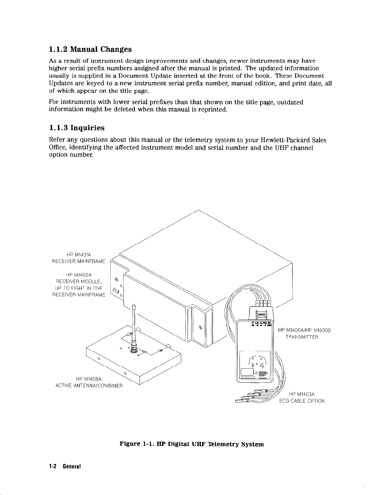
HP M1401A
RECEIVER MAINFRAME
HP M1402A
RECEIVER MODULE,
UP TO EIGHT IN ONE
RECEIVER MAINFRAME
HP M1408A
ACTIVE ANTENNA/COMBINER
l-2 General
Figure l-l. HP Digital UHF Telemetry System
Page 17
1.1.4 Unpacking and Inspection Open the shipping container and examine the instrument for visible damage such as dents
or scratches on the front panel surfaces. If the shipping carton is undamaged, check the
cushioning material and
note
any signs of severe stress as
an
indication of rough handling
in transit. Inspecting the packaging material may be necessary to support claims for hidden
damage that may become apparent only during subsequent testing. Retain the packaging
material for possible re-use.
Check
Performance checks are given later in this section, to verify
the
electrical performance of the instrument as soon as possible after installation.
that
the instruments are operating
within the specifications listed in Section 2.
1.1.5 Claims and Repackaging
If physical damage is evident or if the instruments do not meet specified operating
requirements when received, notify the carrier and the nearest Hewlett-Packard Sales Office.
Hewlett-Packard will arrange for immediate repair or replacement of the unit without waiting
for claim settlement by the carrier.
If the defective unit is to be shipped to a Hewlett-Packard Sales Office, securely attach a tag
showing the name and address of the owner, the instrument model and serial numbers, and
the repair required (or symptoms of fault). If available and reusable, the original HP shipping
container
will
provide proper protection to
the
unit in transit. If the original container is not
reusable or repairable, the Hewlett-Packard Sales Office will provide information about proper
packaging materials and methods.
1.1.6 Functional Description
The Hewlett-Packard HP M1403A Digital UHF Telemetry System consists of a pocket-sized
transmitter with removable lead set, a modular receiver, and a mainframe that accommodates
up to eight receiver channels.
System Functions.
The HP M1403A provides ECG information, alarms, inoperative indications
(INOPs) and status information for up to eight patients. Installed on a Serial Distribution
Network (SDN), the HP M1403A functions like eight individual bedside monitors with patient
data appearing either at an HP Central Monitor or at
an
HP 78508A Patient Information Center
(PIC). A receiver mainframe with eight receiver modules is equivalent to eight patient bedside
stations, and a maximum of 24 patient bedsides may reside on one SDN system. Displays,
control functions (such as gain), recordings and alarms are controlled from the central station.
Recordings also may be initiated from
the
transmitter. Extended system functions such as
bedside overview, remote arrhythmia monitoring, remote data management, and remote
clinical data access is provided by some central stations.
Operation.
Using UHF radio waves, the transmitter sends two digitized ECG signals to a
receiver module in the associated mainframe. These signals (ECG 1 and ECG 2) can either be
passed on directly for display over the SDN, or can be used to derive other cardiac vectors
(reconstructed leads).
The transmitter supports a three-electrode set for single lead operation, and a four- or
five-electrode set for dual-lead operation. Both ECG leads have pace-pulse detection in the
transmitter, which improves detection of pacemaker signals. Each channel
has
user-selectable
bandwidth and gain setting to optimize display and Cardiotach monitoring, and minimize false
alarms.
General l-3
Page 18
When the system is monitoring two leads at the same time, either of these signals may be
displayed and used for heart rate. When the four-wire cable is used with standard electrode
placement, any two of the following leads can be selected for display or used for heart rate:
Leads I, II, III, aVF, aVR or aVL.
Transmitter.
molded plastic case and
Both the HP M1400A and HP M1400B transmitters are enclosed in a
can
be powered by any standard nine-volt battery, subject to the
life-expectancy limits listed in ‘Pdble l-3, Specifications, for different types of batteries.
The transmitters’ button may be configured at installation to transmit a nurse-call request
and/or generate a strip recording, or may be permanently disabled. The button functions
can be disabled by the user with the button on-off key at the central station on a per-patient
basis. Because no other controls are patient-accessible, the transmitter cannot be turned off
inadvertently.
To eliminate the potential confusion of displaying incorrect patient data due to crosstalk or
malfunction, each transmitter transmits a unique identity (ID) code. The transmitter button is
used during installation to set up the transmitter ID code with a companion receiver.
The diference between the HP M1400A and HP M1400B is in output power only. The HP
M1400A transmits at 2 milliwatts; the HP M1400B transmits at 4 milliwatts.
Receiver Mainframe.
The HP M1401A Receiver Mainframe contains up to eight HP M1402A
Receiver Modules, each of which is frequency-matched to the corresponding transmitter.
The mainframe provides indicators to identify hardware and software failures. It calculates the
heart rate from ECG A for each receiver module, and transmits the result with the ECG wave
information and any alarms, INOPs, and status information over the SDN.
In the event of an electrode INOP condition in multi-lead configurations, the receiver
mainframe can be configured for fallback mode so it will switch automatically from the
inoperative lead (normally ECG A) to a secondary lead (normally ECG B), if available. Under
extended monitoring, with the four-electrode lead set, if both the ECG A and ECG B leads are
inoperative, the Cardiotach will switch to another lead, if available.
The mainframe also initiates a recording and/or nurse call alarm at the central station if the
transmitter button is pressed. These functions are enabled or disabled during configuration.
A BNC connector on the mainframe is used to connect with the antenna system output. The
BNC connector is connected to a network that distributes the combined RF signal to each
receiver module.
Patient Monitor/Halter Recorder Interface (Analog Output) Option.
The Patient
Monitor/Halter Recorder Interface option (hereafter referred to as the Analog Output option)
increases the capability of the HP M1403A by providing
an
analog version of ECG waveforms
to bedside monitors and Holter recorders. The option also provides synthesized pace pulse
waveforms, and a Leads Off INOP when leads-off, battery-dead, invalid data and system
malfunctions are detected.
ST Segment Analysis and Two-Channel Delayed Recording Option.
The ST Segment
Analysis provides the capability to calculate ST segment depression or elevation simultaneously
on two channels of ECG. The two measurements are updated every 15 seconds and are
continuously displayed. In addition, the user can enable and disable individual ST channels,
and is notified of INOP due to artifact.
l-4 General
Page 19
With the Two-Channel Delayed Recording option, the user can initiate two-channel manual
or automatic delayed recordings through a PIC-manually by pressing the nurse call button,
or automatically by patient alarm. The recorder strip contains data beginning 10 seconds
prior to the initiation and ending 5 seconds after the initiation, for a total run time of 15
seconds. Delayed recordings may be preempted by recordings of a higher priority and saved as
superseded data. Delayed recordings can be cancelled entirely by pressing the STOP button on
the
recorder faceplate.
Antenna System.
The Dynamic UHF Antenna System minimizes signal-to-noise degradation by
using high-performance, active antenna/combiners with integrated amplifiers to ensure uniform
performance throughout the covered area.
1.1.7 Ordering Information
HP M1403A System Options
Note:
HP M1403A frequency options are listed in Tables l-l and l-2.
The standard system is specified by HP M1403A and one option between A01 and A08. Each
system consists of one or more transmitters with matched receiver modules and one mainframe
with SDN system output. Order ECG cables separately.
Channel System, includes 1 transmitter, 1 receiver module, and 1
A01
A02
A03
A04
A05
A06
A07
A08
Separate Instrument Options
1
Channel
2
Channel System, includes 3 transmitters, 3 receiver modules, and
3
Channel System, includes 4 transmitters, 4 receiver modules, and
4
Channel System, includes 5 transmitters, 5 receiver modules, and
5
Channel System, includes 6 transmitters, 6 receiver modules, and
6
Channel System, includes 7 transmitters, 7 receiver modules, and
7
Channel System, includes 8 transmitters, 8 receiver modules, and
8
System,
includes 2 transmitters, 2 receiver modules, and
mainframe.
1 mainframe.
1 mainframe.
1 mainframe.
1 mainframe.
1 mainframe.
1 mainframe.
1 mainframe.
A10 Replacement transmitter
All
Al2
Al3
Additional transmitter with receiver module, matched pair
Additional receiver module
Additional mainframe only, standard SDN output
co3 Receiver Mainframe with 40 Mhz CPC card
Output Options
co1 ST Segment Analysis/Two-Channel Delayed Recording
JO1 Patient Monitor/Halter Recorder Interface
ECG Cable Options
KOl
K20
K21
K22
K23
K24
K25
K30
K31
K32
K33
K34
K35
Disposable pouch accessory kit
3-lead patient cable with snap connector (USA)
3-lead patient cable with grabber connector (USA)
4-lead patient cable with snap connector (USA)
4-lead patient cable with grabber connector (USA)
5-lead patient cable with snap connector (USA)
5-lead patient cable with grabber connector (USA)
3-lead patient cable with snap connector (IEC)
3-lead patient cable
with
grabber connector (IEC)
4-lead patient cable with snap connector (IEC)
4-lead patient cable with grabber connector (IEC)
5-lead patient cable with snap connector (IEC)
5-lead patient cable with grabber connector (IEC)
General l-5
Page 20
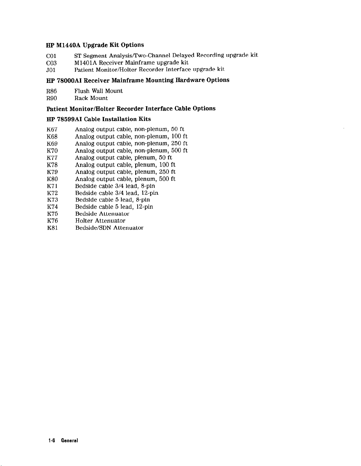
HP M1440A Upgrade Kit Options
co1
co3
JO1
HP 78000AI Receiver Mainframe Mounting Hardware Options
R86
R90
Fdtient Monitor/Halter Recorder Interface Cable Options
HP 78599AI Cable Installation Kits
K67
K68
K69
K70
K77
K78
K79
K80
K71
K72
K73
K74
K75
K76
K81
ST Segment Analysis/Two-Channel Delayed Recording upgrade kit
M1401A Receiver Mainframe upgrade kit
Patient Monitor/Halter Recorder Interface upgrade kit
Flush Wall Mount
Rack Mount
Analog output cable, non-plenum, 50 ft
Analog output cable, non-plenum, 100 ft
Analog output cable, non-plenum, 250 ft
Analog output cable, non-plenum, 500 ft
Analog output cable, plenum, 50 ft
Analog output cable, plenum, 100 ft
Analog output cable, plenum, 250 ft
Analog output cable, plenum, 500 ft
Bedside cable 314 lead, 8-pin
Bedside cable 314 lead, 12-pin
Bedside cable 5 lead, 8-pin
Bedside cable 5 lead, 12-pin
Bedside Attenuator
Holter Attenuator
Bedside/SDN Attenuator
l-6 General
Page 21
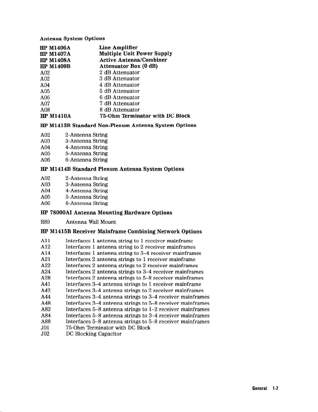
Antenna System Options
HP M1406A
HP M1407A
HP M1408A
HP M1409B
A02
A02
A04
A05
A06
A07
A08
HP M1410A
HP M1413B Standard Non-Plenum Antenna System Options
A02
A03
A04
A05
A06
HP M1414B Standard Plenum Antenna System Options
A02
2-Antenna String
3-Antenna String
4-Antenna String
5-Antenna String
6-Antenna String
2-Antenna String
Line Amplifier
Multiple Unit Power Supply
Active Antenna/Combiner
Attenuator Box (0 dB)
2 dB Attenuator
3 dB Attenuator
4 dB Attenuator
5 dB Attenuator
6 dB Attenuator
7 dB Attenuator
8 dB Attenuator
75-Ohm Terminator with DC Block
A03 3-Antenna String
A04 4-Antenna String
A05
A06
5-Antenna String
6-Antenna String
HP 78000AI Antenna Mounting Hardware Options
R89
HP M1415B Receiver Mainframe Combining Network Options
All
Al2
Al4
A21
A22
A24
A28
A41
A42
A44
A48
A82
A84
A88
JO1
JO2
Antenna Wall Mount
Interfaces 1 antenna string to 1 receiver mainframe
Interfaces 1 antenna string to 2 receiver mainframes
Interfaces 1 antenna string to 3-4 receiver mainframes
Interfaces 2 antenna strings to 1 receiver mainframe
Interfaces 2 antenna strings to 2 receiver mainframes
Interfaces 2 antenna strings to 3-4 receiver mainframes
Interfaces 2 antenna strings to 5-8 receiver mainframes
Interfaces 3-4 antenna strings to 1 receiver mainframe
Interfaces 3-4 antenna strings to 2 receiver mainframes
Interfaces 3-4 antenna strings to 3-4 receiver mainframes
Interfaces 3-4 antenna strings to 5-8 receiver mainframes
Interfaces 5-8 antenna strings to l-2 receiver mainframes
Interfaces 5-8 antenna strings to 3-4 receiver mainframes
Interfaces 5-8 antenna strings to 5-8 receiver mainframes
75-Ohm Terminator with DC Block
DC Blocking Capacitor
General l-7
Page 22
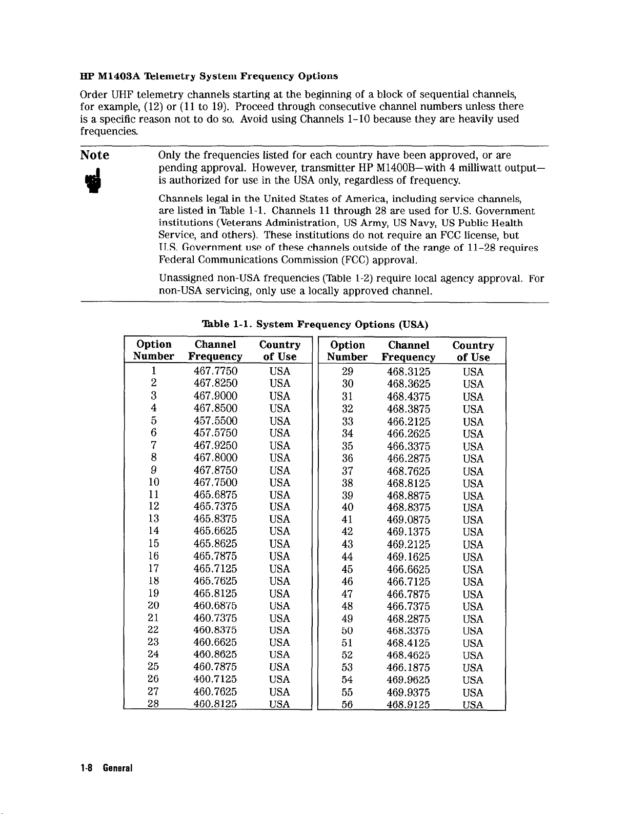
HP M1403A Telemetry System Frequency Options
Order UHF telemetry channels starting at the beginning of a block of sequential channels,
for example, (12) or (11 to 19). Proceed through consecutive channel numbers unless there
is a specific reason not to do so. Avoid using Channels l-10 because they are heavily used
frequencies.
Only
the
Note
frequencies listed for each country have been approved, or are
pending approval. However, transmitter HP M1400B-with 4 milliwatt outputis authorized for use in the USA only, regardless of frequency.
Channels legal in the United States of America, including service channels,
are listed in ‘Ihble l-l. Channels 11 through 28 are used for U.S. Government
institutions (Veterans Administration, US Army, US Navy, US Public Health
Service, and others). These institutions do not require an FCC license, but
U.S. Government use of these channels outside of the range of 11-28 requires
Federal Communications Commission (FCC) approval.
Unassigned non-USA frequencies (Table l-2) require local agency approval. For
non-USA servicing, only use a locally approved channel.
‘kble l-l. System Frequency Options (USA)
Option Channel
Number Freauencv of Use
1
2
467.7750 USA
467.8250
3 467.9000
4
5
6
7
8
467.8500
457.5500 USA
457.5750
467.9250
467.8000
9 467.8750
10
11
12
467.7500
465.6875
465.7375
13 465.8375
14
15
16
17
465.6625
465.8625 USA
465.7875
465.7125
18 465.7625
19 465.8125
20 460.6875
21
22
23
24
25
460.7375
460.8375 USA
460.6625
460.8625 USA
460.7875
26 460.7125
27
460.7625 USA
28 460.8125
Country Option
USA
USA
USA
USA
USA
USA
USA
USA
USA
USA
USA
USA
USA
USA
USA
USA
USA
USA
USA
USA
USA
USA
Channel
Number Frequency
29
30
468.3125 USA
468.3625
Country
31 468.4375
32 468.3875 USA
33
466.2125
34 466.2625 USA
35
466.3375
36 466.2875
37
38
468.7625
468.8125
39 468.8875 USA
40 468.8375
41
42
43
469.0875
469.1375 USA
469.2125
44 469.1625
45
466.6625
46 466.7125
47 466.7875 USA
48 466.7375 USA
49 468.2875 USA
50
51
52
53
468.3375
468.4125
468.4625
466.1875
54 469.9625
55 469.9375
56
468.9125
of Use
USA
USA
USA
USA
USA
USA
USA
USA
USA
USA
USA
USA
USA
USA
USA
USA
USA
USA
USA
USA
1-8 General
Page 23
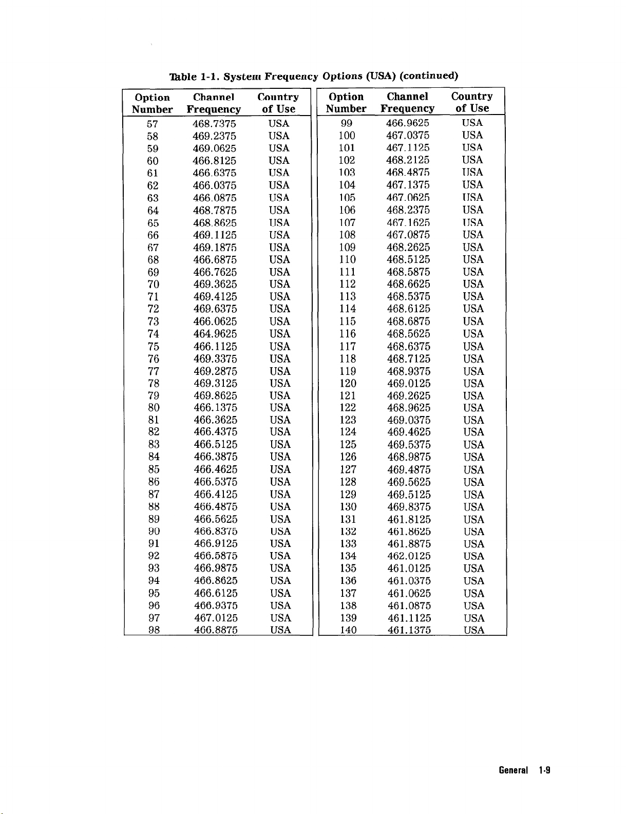
‘Ihble l-l. System Frequency Options (USA) (continued)
Option
Number Frequency
57
58
59
60
61
62
63
64
65
66
67
68
69
70
71
72
73
74
75
76
Channel
468.7375 USA
469.2375
469.0625 USA
466.8125 USA
466.6375
466.0375
466.0875 USA
468.7875 USA
468.8625 USA
469.1125 USA
469.1875 USA
466.6875 USA
466.7625
469.3625 USA
469.4125 USA
469.6375
466.0625 USA
464.9625 USA
466.1125
469.3375
77 469.2875 USA
78
79
469.3125
469.8625
80 466.1375 USA
81 466.3625 USA
82
466.4375
83 466.5125
84 466.3875
85
466.4625
86 466.5375
87 466.4125
88 466.4875
89
90
91
466.5625
466.8375
466.9125
92 466.5875
93 466.9875 USA
94 466.8625 USA
95 466.6125 USA
96 466.9375
97 467.0125 USA
98
466.8875 USA
Country
of Use
USA
USA
USA
USA
USA
USA
USA
USA
USA
USA
USA
USA
USA
USA
USA
USA
USA
USA
USA
USA
USA
Option
Number Freauencs
99
Channel Country
466.9625
100 467.0375
101
102
103
104
105
106
107
108
467.1125 USA
468.2125 USA
468.4875 USA
467.1375 USA
467.0625 USA
468.2375 USA
467.1625 USA
467.0875 USA
109 468.2625 USA
110 468.5125 USA
111
112
113
114
468.5875 USA
468.6625 USA
468.5375
468.6125 USA
115 468.6875 USA
116 468.5625 USA
117
468.6375 USA
118 468.7125
119 468.9375
120 469.0125
121
122
123
124
125
126
127
128
129
130
131
132
469.2625
468.9625 USA
469.0375
469.4625
469.5375 USA
468.9875 USA
469.4875
469.5625
469.5125 USA
469.8375
461.8125
461.8625
133 461.8875
134 462.0125
135 461.0125
136
137
461.0375
461.0625 USA
138 461.0875
139 461.1125
140 461.1375 USA
of Use
USA
USA
USA
USA
USA
USA
USA
USA
USA
USA
USA
USA
USA
USA
USA
USA
USA
USA
USA
USA
General l-9
Page 24
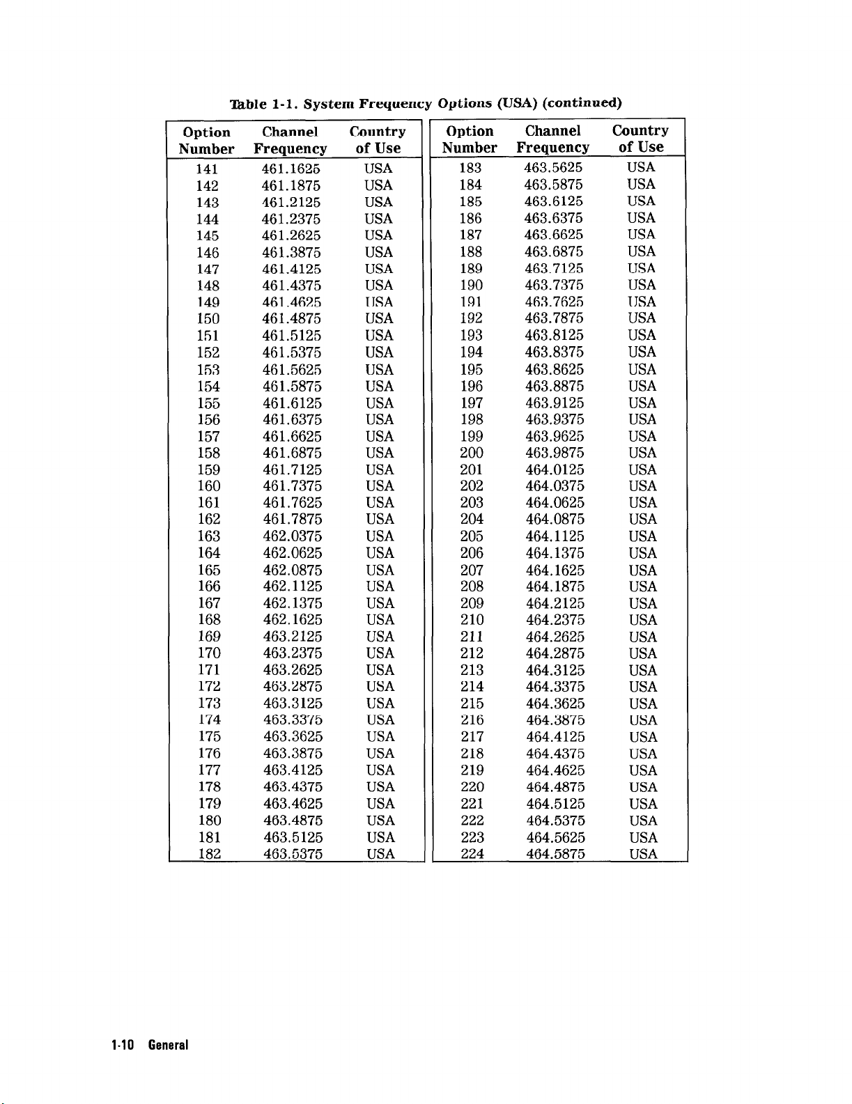
able l-l. System Frequency Options (USA) (continued)
Option
Number Frequency of Use
141
142
143
144
145
146
147
148
149
150
151
152
153
154
155
156
157
158
159
160
161
162
163
164 462.0625
165 462.0875
166
167 462.1375
168
169
170 463.2375
171
172
173 463.3125
174 463.3375
175 463.3625
176 463.3875
177
178 463.4375
179 463.4625
180
181 463.5125
182 463.5375
Channel Country
461.1625
461.1875
461.2125
461.2375
461.2625
461.3875
461.4125
461.4375
461.4625
461.4875
461.5125
461.5375
461.5625
461.5875
461.6125
46 1.6375
461.6625
461.6875
461.7125
461.7375
461.7625
461.7875
462.0375
USA
USA
USA
USA
USA
USA
USA
USA
USA
USA
USA
USA
USA
USA
USA
USA
USA
USA
USA
USA
USA
USA
USA
USA
USA
462.1125
USA
USA
462.1625
463.2125
USA
USA
USA
463.2625
463.2875
USA
USA
USA
USA
USA
USA
463.4125
USA
USA
USA
463.4875
USA
USA
USA
Option
Number Frequency
183
184
185
186
187
188
189
190
Channel Country
of Use
463.5625
463.5875
463.6125 USA
463.6375 USA
463.6625 USA
463.6875 USA
463.7125 USA
463.7375 USA
191 463.7625 USA
192 463.7875 USA
193
194
195
463.8125 USA
463.8375 USA
463.8625 USA
196 463.8875 USA
197 463.9125 USA
198 463.9375 USA
199 463.9625 USA
200 463.9875 USA
201 464.0125
202 464.0375 USA
203 464.0625 USA
204 464.0875
205
206
464.1125
464.1375
207 464.1625 USA
208 464.1875 USA
209 464.2125
210
211
212
213
214
464.2375
464.2625
464.2875
464.3125
464.3375
215 464.3625
216
464.3875
217 464.4125
218 464.4375
219
464.4625 USA
220 464.4875
221
222
464.5125
464.5375
223 464.5625 USA
224
464.5875
USA
USA
USA
USA
USA
USA
USA
USA
USA
USA
USA
USA
USA
USA
USA
USA
USA
USA
USA
USA
l-10 General
Page 25
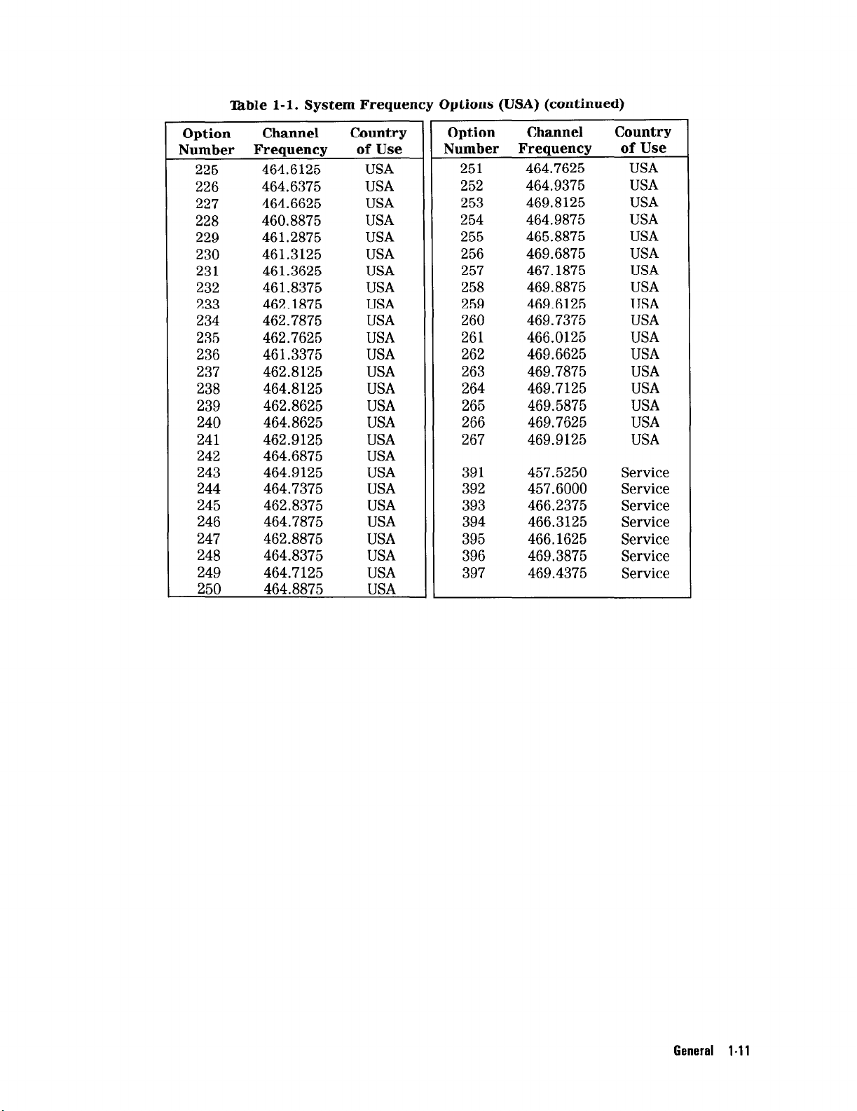
‘lhble l-l. System Frequency Options (USA) (continued)
Option
Number Frequency
Channel Country
225 464.6125
226 464.6375
227 464.6625
228 460.8875
229 461.2875
230 461.3125
231 461.3625
232 461.8375
233 462.1875
234 462.7875
235 462.7625
236 461.3375
237 462.8125
238 464.8125
239 462.8625
240 464.8625
241 462.9125
242 464.6875
243 464.9125
244 464.7375
245 462.8375
246 464.7875
247 462.8875
248 464.8375
249 464.7125
250 464.8875
of Use
USA
USA
USA
USA
USA
USA
USA
USA
USA
USA
USA
USA
USA
USA
USA
USA
USA
USA
USA
USA
USA
USA
USA
USA
USA
USA
Option
Number Frequency
Channel
Country
of Use
251 464.7625 USA
252 464.9375 USA
253 469.8125 USA
254 464.9875 USA
255 465.8875 USA
256 469.6875 USA
257 467.1875 USA
258 469.8875 USA
259 469.6125 USA
260 469.7375 USA
261 466.0125 USA
262 469.6625 USA
263 469.7875 USA
264 469.7125 USA
265 469.5875 USA
266 469.7625 USA
267 469.9125 USA
391 457.5250 Service
392 457.6000 Service
393 466.2375 Service
394 466.3125 Service
395 466.1625 Service
396 469.3875 Service
397 469.4375 Service
General l-11
Page 26
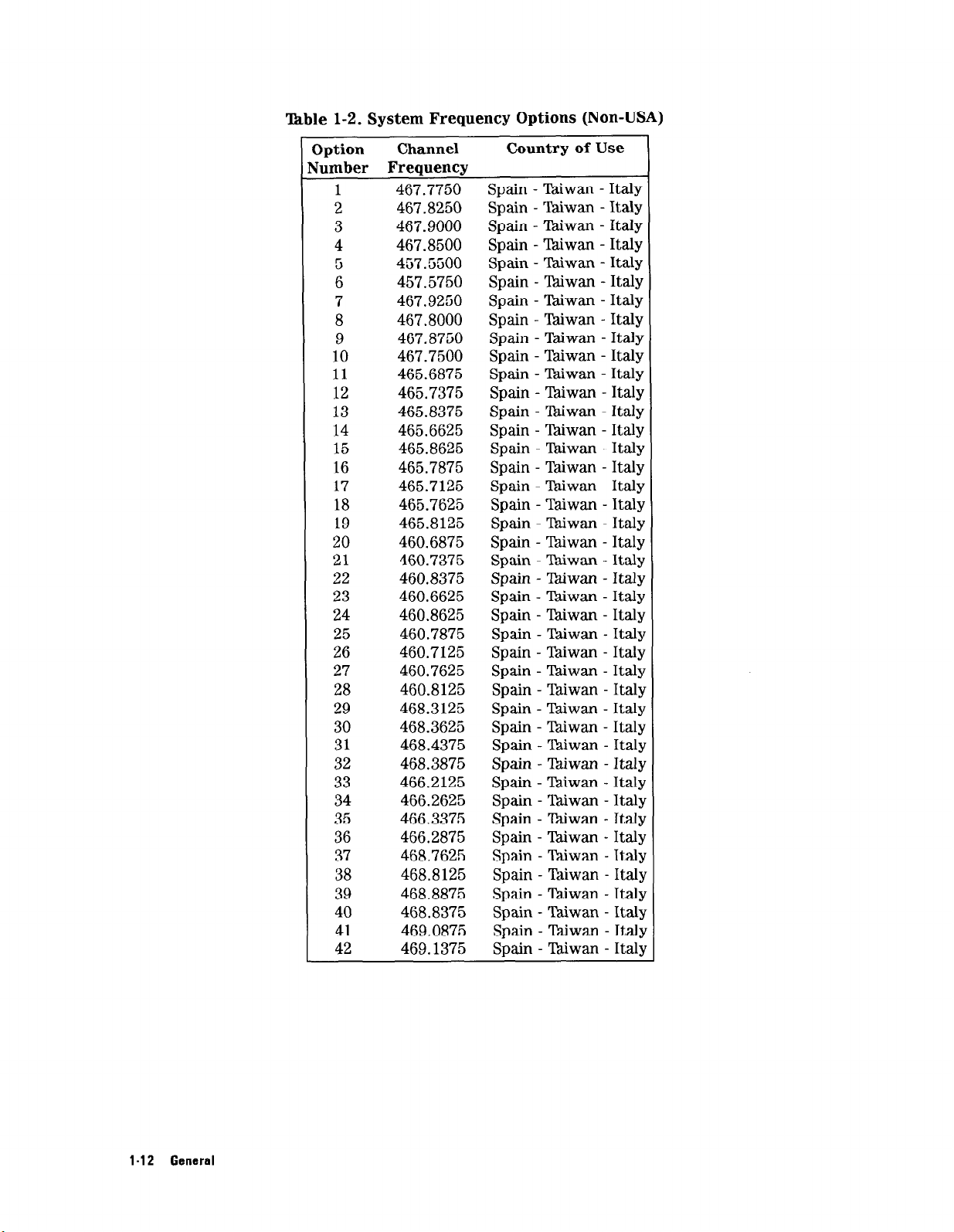
T&ble l-2. System Frequency Options (Non-USA)
3ption
Jumber Frequency
1
2
3
4
5
6
7
8
9
10
11
12
13
14
15
16
17
18
19
20
21
22
23
24
25
26
27
28
29
30
31
32
33
34
35
36
37
38
39
40
41
42
Channel
467.7750
467.8250
467.9000
467.8500
457.5500
457.5750
467.9250
467.8000
467.8750
467.7500
465.6875
465.7375
465.8375
465.6625
465.8625
465.7875
465.7125 Spain - Diwan - Italy
465.7625
465.8125 Spain - lkiwan - Italy
460.6875
460.7375
460.8375
460.6625
460.8625
460.7875
460.7125 Spain - Taiwan - Italy
460.7625
460.8125 Spain - Taiwan - Italy
468.3125 Spain - Thiwan - Italy
468.3625
468.4375
468.3875 Spain - Thiwan - Italj
466.2125
466.2625 Spain - Ylkiwan - Itall
466.3375 Spain - Biwan - Italy
466.2875
468.7625
468.8125
468.8875
468.8375
469.0875 Spain - lkiwan - Ital
469.1375
Country of Use
Spain - Taiwan - Italy
Sbain - Tmiwan - Italy
Spain - Taiwan - Italy
Spain - Tkiwan - Italy
Spain - Taiwan - Italy
Spain - Thiwan - Italy
Spain - Taiwan - Italy
Spain - Wwan - Italy
Spain - Taiwan - Italy
Spain - Thiwan - Italy
Spain - Biwan - Italy
Spain - lhiwan - Italy
Spain - Biwan - Italy
Spain - Taiwan - Italy
Spain - Wwan - Italy
Spain - YIhiwan - Italy
Spain - Taiwan - Italy
Spain - Taiwan - Italy
Spain - lkiwan - Italy
Spain - Lhiwan - Italy
Spain - Taiwan - Italy
Spain - Taiwan - Italy
Spain - Tdiwan - Italy
Spain - Taiwan - Italy
Spain - Ykiwan - Italy
Spain - Thiwan - Italy
Spain - TIMwan - Italy
Spain - Tkiwan - ItaIq
Spain - Taiwan - Italy
Spain - Taiwan - Ital
Spain - Taiwan - Itall
Spain - Taiwan - Italy
Spain - Tdiwan - Ital
1-12 General
Page 27
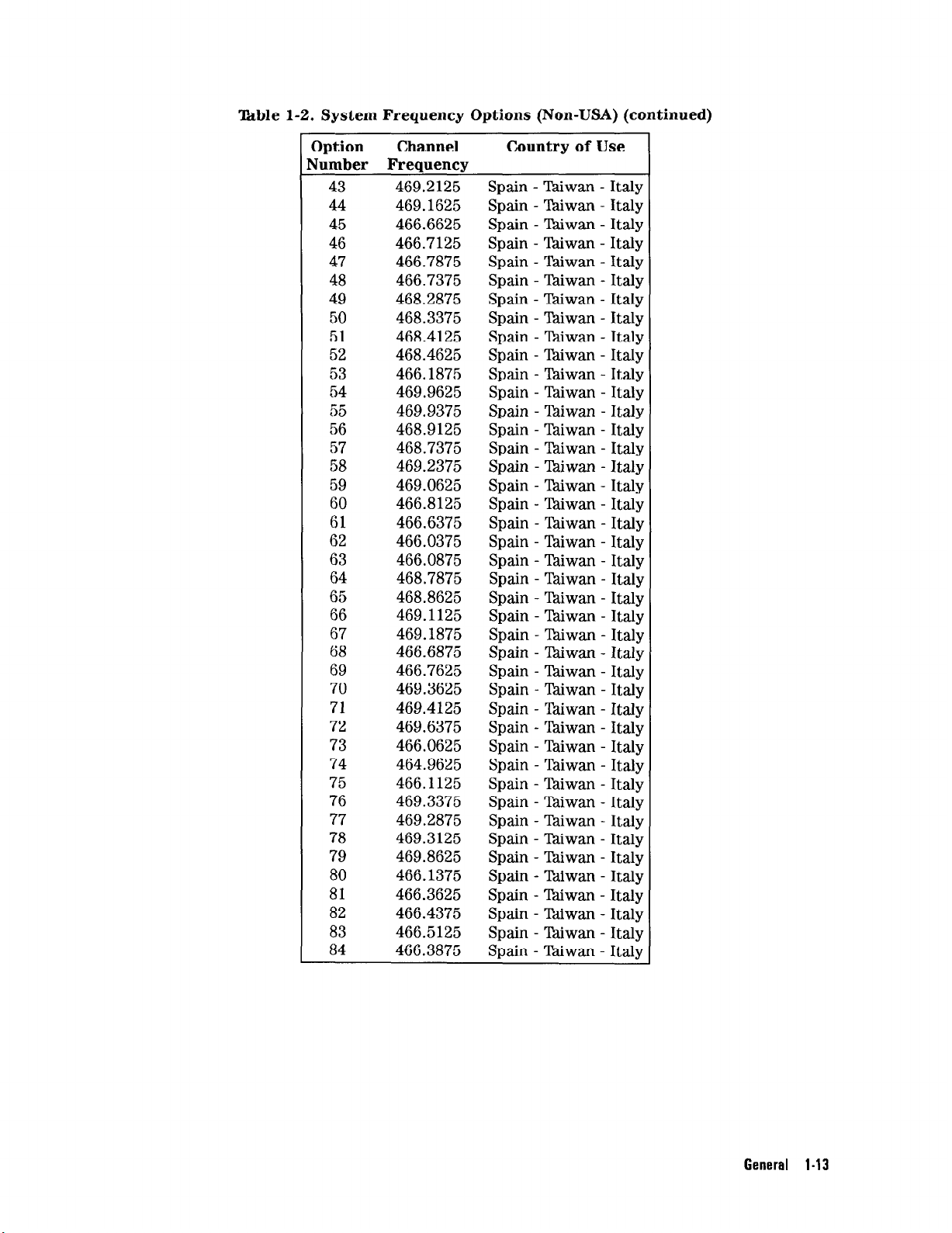
‘kble 1-2. System Frequency Options (Non-USA) (continued)
Option
Jumber Frequency
43
44
45
46
47
48
49
50
51
52
53
54
55
56
57
58
59
60
61
62
63
64
65
66
67
68
69
70
71
72
73
74
75
76
77
78
79
80
81
82
83
84
Channel
469.2125
469.1625
466.6625
466.7125
466.7875
466.7375
468.2875
468.3375
468.4125
468.4625
466.1875
469.9625
469.9375
468.9125
468.7375
469.2375
469.0625
466.8125
466.6375
466.0375
466.0875
468.7875
468.8625
469.1125
469.1875
466.6875
466.7625
469.3625
469.4125
469.6375
466.0625
464.9625
466.1125
469.3375
469.2875
469.3125
469.8625
466.1375
466.3625
466.4375
466.5125
466.3875
Country of Use
Spain - lkiwan
Spain - lhiwan
Spain - lhiwan
Spain - Taiwan
Spain - lhiwan
Spain - Taiwan
Spain - Ykiwan
Spain - Yhiwan
Spain - l%iwan
Spain - T%iwan
Spain - Taiwan
Spain - Taiwan
Spain - Taiwan
Spain - lhiwan
Spain - X&wan
Spain - Tdiwan
Spain - lkiwan
Spain - l%iwan
Spain - lhiwan
Spain - Taiwan
Spain - lhiwan
Spain - Tkiwan
Spain - ‘Pdiwan
Spain - 7Mwan
Spain - Tkiwan
Spain - Thiwan
Spain - lhiwan
Spain - Taiwan
Spain - Tkiwan
Spain - Wwan
Spain - lhiwan
Spain - Taiwan
Spain - lhiwan
Spain - Taiwan
Spain - Tkiwan
Spain - Wwan
Spain - lhiwan
Spain - lkiwan
Spain - Biwan
Spain - Tbiwan
Spain - lhiwan
Spain - Biwan
- Italy
- Italy
- Italy
- Italy
- Italy
- Italy
- Italy
- Italy
- Italy
- Italy
- Italy
- Italy
- Italy
- Italy
- Italy
- Italy
- Italy
- Italy
- Italy
- Italy
- Italy
- Italy
- Italy
- Italy
- Italy
- Italy
- Italy
- ItalJm
- Italy
- Italy
- Italy
- Italy
- Italj
- Ital)
- Italy
- Italy
- Italy
- Ttalq
- Italy
- Italy
- Italy
- Italy
General I-13
Page 28
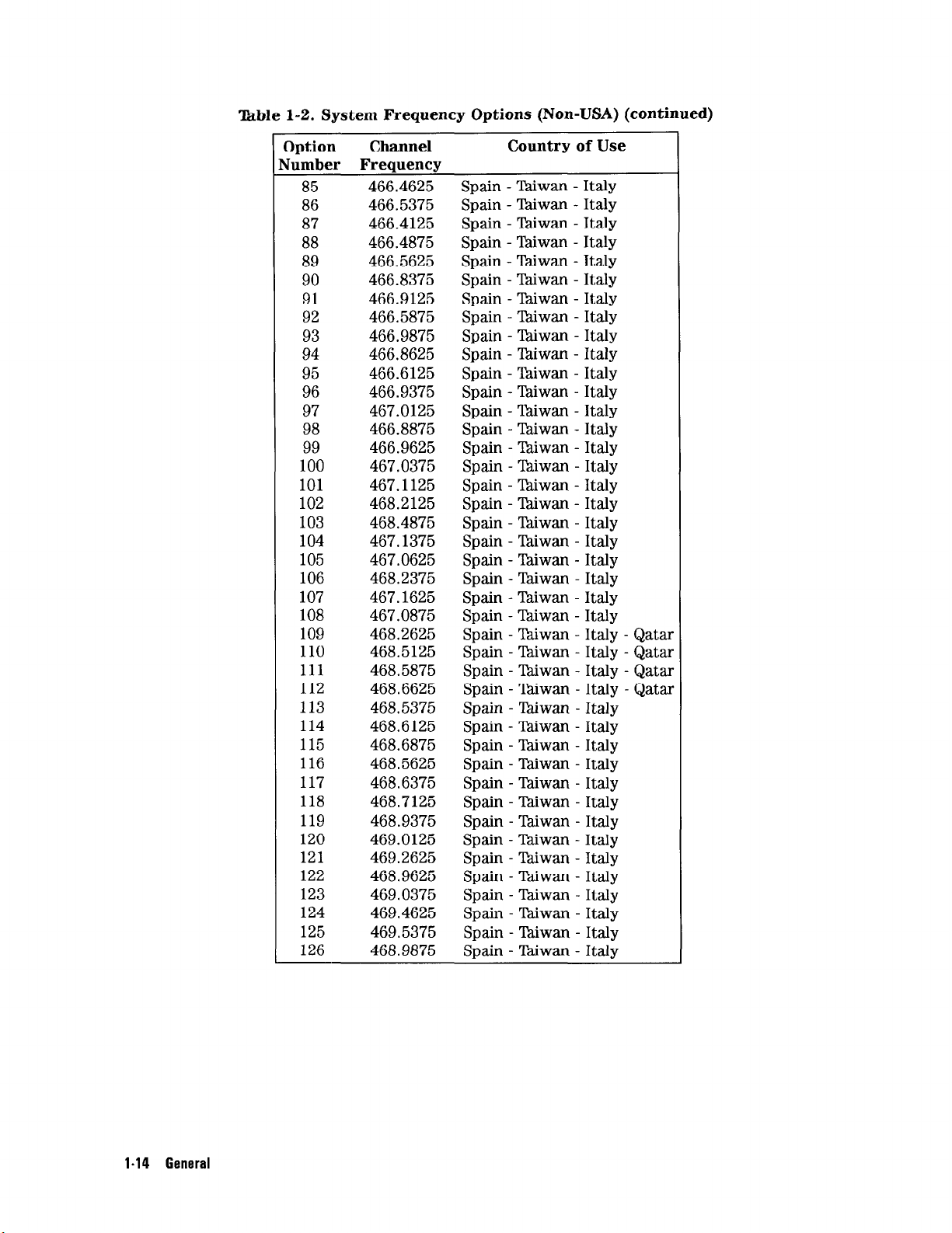
Ikble 1-2. System Frequency Options (Non-USA) (continued)
Option
dumber Frequency
Channel
85 466.4625
86 466.5375
87 466.4125
88 466.4875
89 466.5625
90 466.8375
91 466.9125
92 466.5875
93 466.9875
94 466.8625
95 466.6125
96 466.9375
97 467.0125
98 466.8875
99 466.9625
100 467.0375
101 467.1125
102 468.2125
103 468.4875
104 467.1375
105 467.0625
106 468.2375
107 467.1625
108 467.0875
109 468.2625
110 468.5125
111 468.5875
112 468.6625
113 468.5375
114 468.6125
115 468.6875
116 468.5625
117 468.6375
118 468.7125
119 468.9375
120 469.0125
121 469.2625
122 468.9625
123 469.0375
124 469.4625
125 469.5375
126 468.9875
Country of Use
Spain - Tkiwan -
Spain - lhiwan Spain - Taiwan Spain - Taiwan Spain - Taiwan Spain - Yt%iwan Spain - Tdiwan Spain - l%.iwan Spain - Ciiwan Spain - Thiwan Spain - %iwan Spain - lhiwan Spain - Taiwan Spain - lkiwan -
Spain - Tdiwan Spain - lkiwan Spain - l%.iwan Spain - lkiwan Spain - Taiwan Spain - Wwan Spain - lhiwan Spain - Taiwan Spain - Taiwan Spain - Ythiwan Spain - ‘Jkiwan Spain - Wwan Spain - ‘hiwan Spain - ‘hiwan Spain - Taiwan Spain - Taiwan Spain - Thiwan Spain - Taiwan Spain - Taiwan Spain - ‘Pdiwan Spain - lkiwan Spain - lhiwan Spain - ‘Pdiwan Spain - Taiwan Spain - Taiwan Spain - Tkiwan -
Spain - Thiwan -
Spain - lkiwan -
Italy
Italy
Italy
Italy
Italy
Italy
Italy
Italy
Italy
Italy
Italy
Italy
Italy
Italy
Italy
Italy
Italy
Italy
Italy
Italy
Italy
Italy
Italy
Italy
Italy - Qatar
Italy - Qatar
Italy - Qatar
Italy - Qatar
Italy
Italy
Italy
Italy
Italy
Italy
Italy
Italy
Italy
Italy
Italy
Italy
Italy
Italy
I-14 General
Page 29
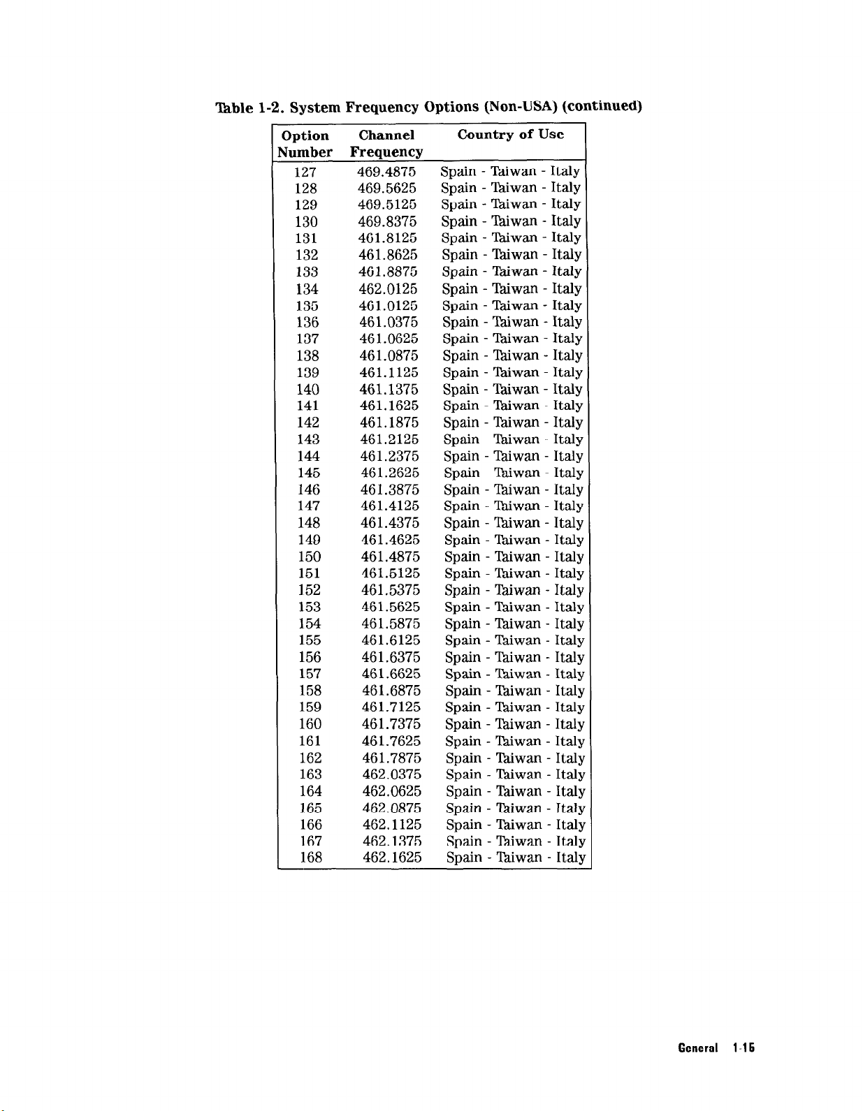
l’hble 1-2. System Frequency Options (Non-USA) (continued)
3ption
lumber Frequency
Channel
Country of Use
127 469.4875 Spain - Taiwan - Italy
128 469.5625 Spain - Zwan - Italy
129 469.5125 Spain - Thiwan - Italy
130 469.8375 Spain - lhiwan - Italy
131 461.8125 Spain - Thiwan - Italy
132 461.8625 Spain - Taiwan - Italy
133 461.8875 Spain - lhiwan - Italy
134 462.0125 Spain - ‘Pdiwan - Italy
135 461.0125 Spain - T&wan - Italy
136 461.0375 Spain - Taiwan - Italy
137 46 1.0625 Spain - Tbiwan - Italy
138 461.0875 Spain - lhiwan - Italy
139 461.1125 Spain - Thiwan - Italy
140 461.1375 Spain - Taiwan - Italy
141 461.1625 Spain - l&wan - Italy
142 461.1875 Spain - Taiwan - Italy
143 461.2125 Spain - lhiwan - Italy
144 461.2375 Spain - lhiwan - Italy
145 461.2625 Spain - ‘Pdiwan - Italy
146 461.3875 Spain - lhiwan - Italy
147 461.4125 Spain - Thiwan - Italy
148 461.4375 Spain - tiwan - Italy
149 461.4625 Spain - Tkiwan - Italy
150 461.4875 Spain - Taiwan - Italy
151 461.5125 Spain - Taiwan - Italy
152 461.5375 Spain - lztiwan - Italy
153 461.5625 Spain - Taiwan - Italy
154 461.5875 Spain - Taiwan - Italy
155 461.6125 Spain - T&wan - Italy
156 461.6375 Spain - Thiwan - Italy
157 461.6625 Spain - Taiwan - Italy
158 461.6875 Spain - Tkiwan - Italy
159 461.7125 Spain - Tkiwan - Italq
160 461.7375 Spain - Taiwan - Italq
161 461.7625 Spain - tiwan - Italy
162 461.7875 Spain - tiwan - Ital)
163 462.0375 Spain - Taiwan - Italy
164 462.0625 Spain - Taiwan - Italj
165 462.0875 Spain - Taiwan - Ital
166 462.1125 Spain - lhiwan - Italy
167 462.1375 Spain - lhiwan - Italy
168 462.1625 Spain - lkiwan - Italy
General l-15
Page 30
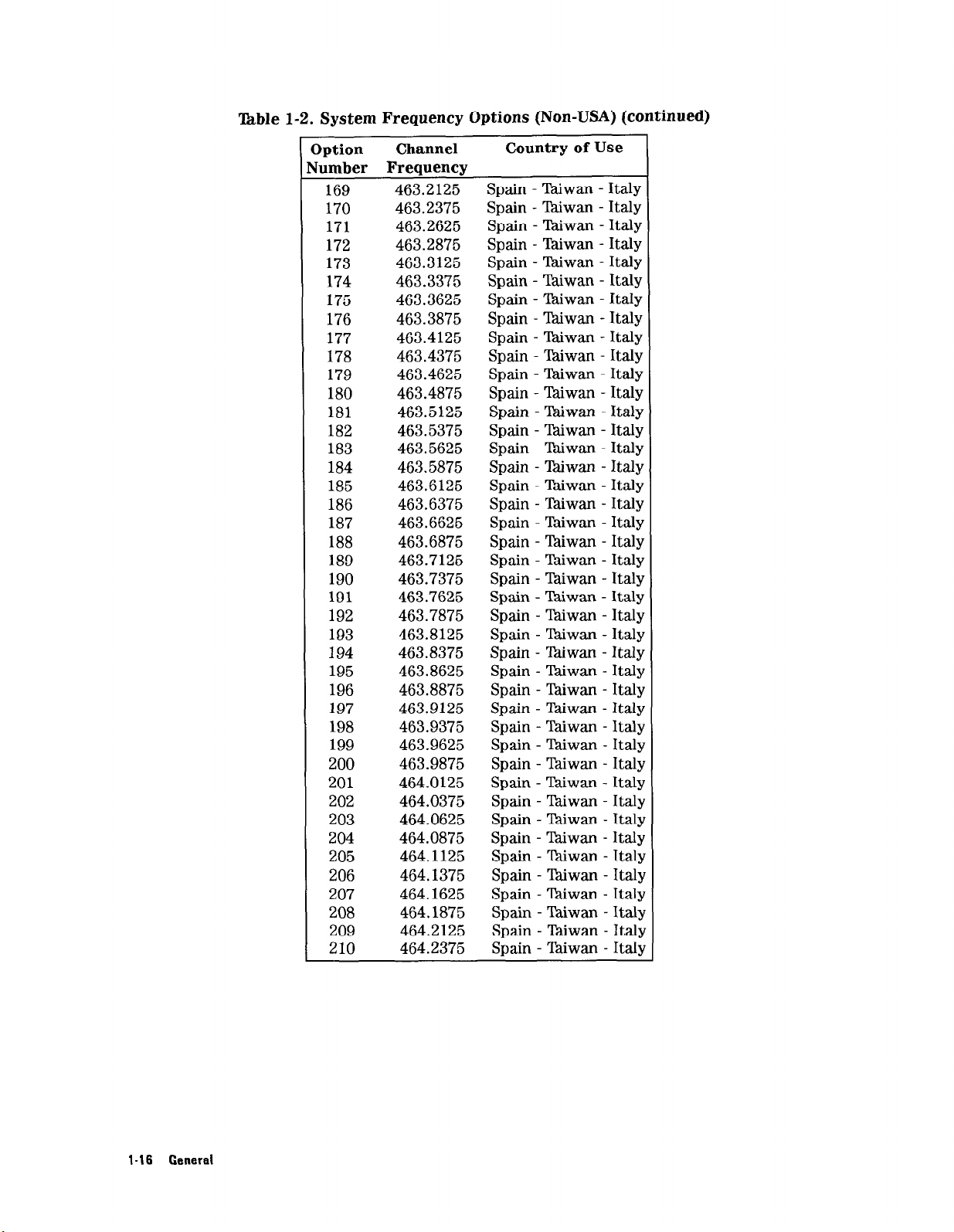
‘kble 1-2. System Frequency Options (Non-USA) (continued)
Iption
lumber Frequency
Channel
Country of Use
169 463.2125 Spain - lhiwan - Italy
170 463.2375 Spain - lhiwan - Italy
171 463.2625 Spain - lhiwan - Italy
172 463.2875 Spain - %iwan - Italy
173 463.3125 Spain - Taiwan - Italy
174 463.3375 Spain - Thiwan - Italy
175 463.3625 Spain - lhiwan - Italy
176 463.3875 Spain - Thiwan - Italy
177 463.4125 Spain - Taiwan - Italy
178 463.4375 Spain - Taiwan - Italy
179 463.4625 Spain - Taiwan - Italy
180 463.4875 Spain - T&wan - Italy
181 463.5125 Spain - Taiwan - Italy
182 463.5375 Spain - Tdiwan - Italy
183 463.5625 Spain - TGwan - Italy
184 463.5875 Spain - l&wan - Italy
185 463.6125 Spain - l%iwan - Italy
186 463.6375 Spain - TPdiwan - Italy
187 463.6625 Spain - lhiwan - Italy
188 463.6875 Spain - Taiwan - Italy
189 463.7125 Spain - lkiwan - Italy
190 463.7375 Spain - Taiwan - Italy
191 463.7625 Spain - Taiwan - Italy
192 463.7875 Spain - Yhiwan - Italy
193 463.8125 Spain - lhiwan - Italy
194 463.8375 Spain - Taiwan - Italy
195 463.8625 Spain - %.iwan - Italy
196 463.8875 Spain - Taiwan - Italy
197 463.9125 Spain - l%iwan - Italy
198 463.9375 Spain - Taiwan - Italy
199 463.9625 Spain - Taiwan - Italy
200 463.9875 Spain - Y&wan - Italy
201 464.0125 Spain - Taiwan - Italy
202 464.0375 Spain - lhiwan - Italy
203 464.0625 Spain - l%iwan - Italy
204 464.0875 Spain - Tdiwan - Italy
205 464.1125 Spain - Thiwan - Italy
206 464.1375 Spain - Biwan - Italy
207 464.1625 Spain - Taiwan - Italy
208 464.1875 Spain - Taiwan - Italy
209 464.2125 Spain - LMwan - Italy
210 464.2375 Spain - Thiwan - Italy
I-16 General
Page 31

‘kble l-2. System Frequency Options (Non-USA) (continued)
Iption
umber Frequency
211
212
213
214
215
216
217
218
219
220
221
222
223
224
225
226
227
228
229
230
231
232
233
234
235
236
237
238
239
240
241
242
243
244
245
246
247
248
249
250
251
252
Channel
464.2625
464.2875
464.3125
464.3375
464.3625
464.3875
464.4125
464.4375
464.4625
464.4875
464.5125
464.5375
464.5625
464.5875
464.6125
464.6375
464.6625
460.8875
461.2875
461.3125
461.3625
461.8375
462.1875
462.7875
462.7625
461.3375
462.8125
464.8125
462.8625
464.8625
462.9125
464.6875
464.9125
464.7375
462.8375
464.7875
462.8875
464.8375
464.7125
464.8875
464.7625
464.9375
Country of Use
Spain - Taiwan - Italy
Spain - %iwan - Italy
Spain - Thiwan - Italy
Spain - Tbiwan - Italy
Spain - lkiwan - Italy
Spain - lhiwan - Italy
Spain - lkiwan - Italy
Spain - lhiwan - Italy
Spain - Taiwan - Italy
Spain - lhiwan - Italy
Spain - Taiwan - Italy
Spain - lhiwan - Italy
Spain - Thiwan - Italy
Spain - Taiwan - Italy
Spain - Yhiwan - Italy
Spain - lhiwan - Italy
Spain - Taiwan - Italy
Spain - %iwan - Italy
Spain - lhiwan - Italy
Spain - Thiwan - Italy
Spain - lhiwan - Ita
Spain - lhiwan - Italy
Spain - lhiwan - Italy
Spain - tiwan - Ital
Spain - Tkiwan - ItaIJ
Spain - Taiwan - Ital)
Spain - Taiwan - Italy
Spain - Taiwan - Ital
Spain - Thiwan - Itall
Spain - Taiwan - Italy
Spain - Taiwan - Ital
Spain - Taiwan - Itall
Spain - ‘Pdiwan - Italy
Spain - T&wan - Italy
Spain - Xwan - Ital!
Spain - !4kiwan - Ital!
Spain - Taiwan - Ital!
Spain - Tkiwan - Ital!
Spain - E&wan - Ital!
Spain - Taiwan - Ital!
Spain - Taiwan - Ital:
Spain - Thiwan - Italy
General 1-17
Page 32

‘Ihble 1-2. System Frequency Options (Non-USA) (continued)
Iption
lumber Frequency
Channel
Country of Use
253 469.8125 Spain - Wwan - Italy
254 464.9875 Spain - Taiwan - Italy
255 465.8875 Spain - lhiwan - Italy
256 469.6875 Spain - Taiwan - Italy
257 467.1875 Spain - Taiwan - Italy
258 469.8875 Spain - Tdiwan - Italy
259 469.6125 Spain - lkiwan - Italy
260 469.7375 Spain - lkiwan - Italy
261 466.0125 Spain - Taiwan - Italy
262 469.6625 Spain - Taiwan - Italy
263 469.7875 Spain - lkiwan - Italy
264 469.7125 Spain - lkiwan - Italy
265 469.5875 Spain - lkiwan - Italy
266 469.7625 Spain - Taiwan - Italy
267 469.9125 Spain - Thiwan - Italy
501 412.6250 Australia - Spain
502 412.6750 Australia - Spain
503 412.7250 Australia - Spain
504 412.7750 Australia - Spain
505 412.8250 Australia - Spain
506 412.7000 Australia - Spain
507 412.6500 Australia - Spain
508 412.7500 Australia - Spain
509 412.8000 Australia - Spain
510 469.5000 Australia - Italy - Spair
511 469.5250 Australia - Italy - Spair
512 469.5500 Australia - Italy - Spair
513 469.5750 Australia - Italy - Spair
514 469.6000 Australia - Italy - Spair
515 469.6250 Australia - Italy - Spair
516 469.6500 Australia - Italy - Spair
517 469.6750 Australia - Italy - Spair
518 469.7000 Australia - Italy - Spail
519 469.7250 Australia - Italy - Spair
520 412.6000 Australia - Spain
521 412.4750 Australia - Spain
522 412.5000 Australia - Spain
523 412.5250 Australia - Spain
524 412.5500 Australia - Spain
525 412.5750 Australia - Spain
526 412.8500 Australia - Spain
527 412.8750 Australia - Spain
1-l 8 General
Page 33

‘lhble 1-2. System Frequency Options (Non-USA) (continued)
3ption
lumber Frequency
528
529
530
531
532
533
534
535
536
537
538
539
540
541
542
543
544
545
Channel
412.9000
412.9250
412.9500
456.2100
456.2500
456.3300
466.2100
466.2500
466.3300
433.1000
434.7000
433.1250
433.1500
433.1750
433.2000
433.2250
433.2500
433.2750
546 433.3000
547
548
433.3250
433.3500
549 433.3750
550
551
552
433.4000
466.8125
466.8375
553 466.8625
554 466.8875
555
470.0250
556 470.0500
557
470.0750
558 470.1000
559
470.1250
560 470.1500
561
562
563
470.1750
470.2000
470.2250
564 470.2500
565
566
470.2750
470.3000
567 470.3250
568
569
470.3500
470.3750
570 470.4000
Country of Use
Australia - Spain
Australia - Spain
Australia - Spain
Canada* - Germany - Turkey - Italy - Spain
Canada* - Germany - Turkey - Italy - Spain
Canada* - Germany - Turkey - Italy - Spain
Canada* - Germany - Turkey - Italy - Spain
Canada* - Germany - Turkey - Italy - Spain
Canada* - Germany
Turkey - Italy - Spain
Switzerland - Spain
Switzerland - Spain
Germany - Turkey
Germany - Turkey
Germany - Turkey
Germany - Turkey
Germany - Turkey
Germany - Turkey
Germany - Turkey
Germany - Turkey
Germany - Turkey
Germany - Turkey
Germany - Turkey
Germany - Turkey
Netherlands - Italy - Spain
Netherlands - Italy - Spain
Netherlands - Italy - Spain
Netherlands - Italy - Spain
Netherlands - New Zealand - Spain
Netherlands - New Zealand - Spain
Netherlands - New Zealand - Spain
Netherlands - New Zealand - Spain
Netherlands - New Zealand - Spain
Netherlands - New Zealand - Spain
Netherlands - New Zealand - Spain
Netherlands - New Zealand - Spain
New Zealand - Spain
New Zealand - Spain
New Zealand - Spain
New Zealand - Spain
New Zealand - Spain
New Zealand - Spain
New Zealand - Spain
New Zealand - Spain
General 1-19
Page 34

Table l-2. System Frequency Options (Non-USA) (continued)
Iption
lumber Frequency
571
572
573
574
575
576
577
578
579
580
581
582
583
584
585
586
587
588
589
590
591
592
593
594
595
596
597
598
599
600
601
602
603
604
605
606
607
608
609
610
611
612
Channel
450.7650
450.7900
450.8150
450.8400
450.8650
450.8900
450.9300
450.9700
451.0100
451.0500
451.0900
450.9150
450.9400
450.9650
451.0150
451.0400
451.0650
433.6750
433.7250
450.9900
433.4250
433.4500
433.4750
433.5000
433.5250
433.5500
433.5750
433.6250
433.6500
433.7000
448.0000
448.0250
448.0750
448.1000
448.2500
448.2750
448.0500
448.1250
448.1500
448.1750
448.2000
448.2250
Country of Use
Canada* - Netherlands - Italy - Spain
Canada* - Netherlands - Italy - Spain
Canada* - Netherlands - Italy - Spain
Canada* - Netherlands - Italy - Spain
Canada* - Netherlands - Italy - Spain
Canada* - Netherlands - Italy - Spain
Canada* - Italy - Spain
Canada* - Italy - Spain
Canada* - Italy - Spain
Canada* - Italy - Spain
Canada* - Netherlands - Italy - Spain
Netherlands - Italy - Spain
Netherlands - Italy - Spain
Netherlands - Italy - Spain
Netherlands - Italy - Spain
Netherlands - Italy - Spain
Netherlands - Italy - Spain
Switzerland - Spain
Switzerland - Spain
Netherlands - Spain
Germany - Turkey
Germany - Turkey
Germany - Turkey
Germany - Turkey
Germany - Turkey
Germany - Turkey
Germany - Turkey
Germany - Turkey
Germany - Turkey
Germany - Turkey
Denmark - Italy - Spain
Denmark - Italy - Spain
Denmark - Italy - Spain
Denmark - Italy - Spain
Denmark - Belgium - Luxembourg - Italy - Spair
Denmark - Belgium - Luxembourg - Italy - Spair
Denmark - Italy - Spain
Denmark - Belgium - Luxembourg - Italy - Spah
Denmark - Belgium - Luxembourg - Italy - Spair
Denmark - Belgium - Luxembourg - Italy - Spair
Denmark - Belgium - Luxembourg - Italy - Spah
Denmark - Belgium - Luxembourg - Italy - Spair
l-20 General
Page 35

able 1-2. System Frequency Options (Non-USA) (continued)
Iption Channel
umber Frequency
621
622
623
624
625
626
627
628
629
630
631
632
633
634
635
636
637
638
639
640
641
446.0500
446.1000
446.3500
446.4000
446.5000
446.5500
446.8000
446.8500
446.0000
446.1500
446.2000
446.4500
446.6000
446.6500
446.9000
446.9500
446.2500
446.3000
446.7000
446.7500
406.8125
642 406.8375
643
406.8625
644 406.8875
645
407.1625
646 407.1875
647
407.4125
648 407.4375
649 407.5000
650 407.5125
651
407.5375
652 407.5500
653
654
407.5625
407.5750
655 407.5875
656 407.6125
657
407.7000
658 407.7125
659
407.8000
660 407.8125
661 407.8250
L
Country of Use
Italy - Spain
Italy - Spain
Italy - Spain
Italy - Spain
Italy - Spain
Italy - Spain
Italy - Spain
Italy - Spain
Italy - Spain
Italy - Spain
Italy - Spain
Italy - Spain
Italy - Spain
Italy - Spain
Italy - Spain
Italy - Spain
Italy - Spain
Italy - Spain
Italy - Spain
Italy - Spain
i
General 1-21
Page 36

mble l-2. System Frequency Options (Non-USA) (continued)
Iption
lumber Frequency
662
663
664
665
666
667
668
669
670
671
672
673
674
675
676
677
678
679
680
681
682
683
684
685
686
687
688
689
690
691
692
693
694
695
696
697
698
699
700
Channel
407.8500
407.8625
407.9000
407.9125
407.9250
407.9375
407.9500
407.9625
407.9750
433.7500 Germany
433.7750 Germany
433.8000 Germany
433.8250 Germany
433.8500 Germany
433.8750 Germany
433.9000 Germany
433.9250 Germany
433.9500 Germany
433.9750 Germany
434.0000 Germany
434.0250 Germany
434.0500 Germany
434.0750 Germany
434.1000 Germany
434.1250 Germany
434.1500 Germany
434.1750 Germany
434.2000 Germany
434.2250 Germany
434.2500 Germany
434.2750 Germany
434.3000 Germany
434.3250 Germany
434.3500 Germany
434.3750 Germany
434.4000 Germany
434.4250 Germany
434.4500 Germany
434.4750 Germany
Country of Use
- Turkey
- Turkey
- Turkey
- Turkey
- Turkey
- Turkey
- Turkey
- Turkey
- Turkey
- Turkey
- Turkey
- Turkey
- Turkey
- Turkey
- Turkey
- Turkey
- Turkey
- Turke]
- Turkey
- Turkey
- Turkey
- Turke]
- Turkey
- Turkey
- Turke]
- Turkey
- Turkey
- Turke]
- Turke!
- Turke!
l-22 General
Page 37

‘Ihble 1-2. System Frequency Options (Non-USA) (continued)
3ption
lumber Frequency
701
702
703
704
705
706
707
708
709
710
711
712
Channel
458.5000
458.5250
458.5625
458.5875
458.7000
458.7250
458.7750
458.8000 Canada* - UK - Ireland - Italy - Spain
458.6250
458.6500
458.6750
458.7500
713 458.9750
721
722
723
724
441.9750
441.9250
441.9850
441.9000
725 441.8750
726 441.9500
727
728
729
730
441.8000
441.8250
441.7500
441.7750
731 441.8500
732 434.5000
733 434.5250
734 434.5500
735
434.5750
736 434.6000
737
434.6250
738 434.6500
739 434.6750
740 434.7250
741 468.5250
742 468.5750
743 468.6250
744 468.6500
745 468.6750
Country of Use
Canada* - UK - Ireland - Italy - Spain
Canada* - UK - Ireland - Italy - Spain
Canada* - UK - Italy - Spain
Canada* - UK - Italy - Spain
Canada* - UK - Ireland - Italy - Spain
Canada* - UK - Ireland - Italy - Spain
Canada* - UK - Ireland - Italy - Spain
UK - Ireland - Italy - Spain
UK - Ireland - Italy - Spain
UK - Ireland - Italy - Spain
UK - Ireland - Italy - Spain
Italy - Spain
Norway - Italy - Spain
Norway - Italy - Spain
Italy - Spain
Norway - Italy - Spain
Norway - Italy - Spain
Norway - Italy - Spain
Norway - Italy - Spain
Norway - Italy - Spain
Norway - Italy - Spain
Norway - Italy - Spain
Norway - Italy - Spain
Germany - Turkey
Germany - Turkey
Germany - Turkey
Germany - Turkey
Germany - Turkey
Germany - Turkey
Germany - Turkey
Germany - Turkey
Germany - Turkey
Finland - Italy - Spain
Finland - Italy - Spain
Finland - Italy - Spain
Finland - Italy - Spain
Finland - Italy - Spain
751 439.7500 Sweden - Italy - Spain
752
439.7750
Sweden - Italy - Spain
753 439.8000 Sweden - Italy - Spain
General 1.23
Page 38

!l -2. System Frequency Options (Non-USA) (continued)
Option
qumber Frequency
754
755
Channel
439.8250
439.8500
756 439.8750
757 439.9500
758 439.9750
759 439.9000
760 439.9250
761 439.7000
762 439.7250
763 438.0500
764 438.0750
765 438.1000
766 438.1500
767
438.1750 Sweden - Italy - Spain
768 438.2000
769 438.2250
770 438.2500
771 438.3000
772 438.3250
Country of Use
Sweden - Italy - Spain
Sweden - Italy - Spain
Sweden - Italy - Spain
Sweden - Italy - Spain
Sweden - Italy - Spain
Sweden - Italy - Spain
Sweden - Italy - Spain
Sweden - Italy - Spain
Sweden - Italy - Spain
Sweden - Italy - Spain
Sweden - Italy - Spain
Sweden - Italy - Spain
Sweden - Italy - Spain
Sweden - Italy - Spain
Sweden - Italy - Spain
Sweden - Italy - Spain
Sweden - Italy - Spain
Sweden - Italy - Spain
773 438.3500 Sweden - Italy - Spain
774
775
438.3750
438.4000
Sweden - Italy - Spain
Sweden - Italy - Spain
776 438.4250 Sweden - Italy - Spain
777 438.4500 Sweden - Italy - Spain
778
438.5000 Sweden - Italy - Spain
779 438.5250 Sweden - Italy - Spain
780 438.5500 Sweden - Italy - Spain
781 438.6000 Sweden - Italy - Spain
782 434.7500 Germany - Turkey
l-24 General
791 433.6000 Switzerland - Italy - Spain
801
802
803
804
805
806
807
808
809
810
449.7750 Canada* - Italy - Spain
449.8000 Canada* - Italy - Spain
449.8500 Canada* - Italy - Spain
449.8250
440.5250
440.5500
Italy - Spain
Italy - Spain
Italy - Spain
440.6250 Italy - Spain
440.7750 Italy - Spain
440.8250
Italy - Spain
445.0000 Italy - Spain
Page 39

able 1-2. System Frequency Options (Non-USA) (continued)
Option
Jumber Frequency
811
812
813
814
815
816
817
818
819
820
821
Channel
467.7750
467.8250
467.9000
467.8500
457.5500
457.5750
467.9250
467.8000
467.8750
467.7500
450.9500
822 451.0300
823
850
851
451.0700
465.8375
465.8625
852 465.7875
853
854
855
856
857
465.7625
457.5250
457.6000
448.3000
448.3250
858 448.3500
859 448.3750
860
448.4000 Italy - Spain - Belgium - Luxembourg - Denmark
Canada* - Belgium - Luxembourg - Italy - Spain
Italy - Spain - Canada*
Italy - Spain - Canada*
Italy - Spain - Canada*
Italy - Spain - Canada*
Italy - Spain - Canada*
Italy - Spain - Canada*
Italy - Spain - Canada*
Italy - Spain - Canada*
Italy - Spain - Canada*
Italy - Spain - Canada*
Italy - Spain - Canada*
Italy - Spain - Canada*
Italy - Spain - Belgium - Luxembourg
Italy - Spain - Belgium - Luxembourg
Italy - Spain - Belgium - Luxembourg
Italy - Spain - Belgium - Luxembourg
Italy - Spain - Belgium - Luxembourg
Italy - Spain - Belgium - Luxembourg
Italy - Spain - Belgium - Luxembourg - Denmark
Italy - Spain - Belgium - Luxembourg - Denmark
Italy - Spain - Belgium - Luxembourg - Denmark
Italy - Spain - Belgium - Luxembourg - Denmark
Country of Use
861 469.3750 Australia - Italy - Spain
862 469.4000 Australia - Italy - Spain
863 469.4250 Australia - Italy - Spain
864 469.4500 Australia - Italy - Spain
865 469.4750 Australia - Italy - Spain
866 469.7500 Australia - Italy - Spain
867 469.7750 Australia - Italy - Spain
868 469.8000 Australia - Italy - Spain
869 469.8250 Australia - Italy - Spain
870 469.8500 Australia - Italy - Spain
871 410.9500
Finland
872 410.9750 Finland
873 411.0000
Finland
874 411.0250 Finland
875 411.0500 Finland
876
877 448.4250
411.0750 Finland
Denmark
878 448.4500 Denmark
- Belgium - Luxembourg
- Belgium - Luxembourg
- Belgium - Luxembourg
- Belgium - Luxembourg
- Belgium - Luxembourg
- Belgium - Luxembourg
- Belgium - Luxembourg
- Belgium - Luxembourg
- Belgium - Luxembourg
General l-25
Page 40

Table 1-2. System Frequency Options (Non-USA) (continued)
Note
d
Option
Number Frequency
879
880
881
882
883
884
885
886
887
888
889
890
891
892
1
893
* Local frequencies are authorized
Communication.
Channel
448.4750
448.5000
458.5500
458.5750
458.6000
458.8250
458.8500
458.8750
458.9000
458.9250
458.9500
472.0250
472.0500
472.0750
472.1000
Country of Use
Denmark
Denmark
Ireland
Ireland
Ireland
Ireland
Ireland
Ireland
Ireland
Ireland
Ireland
Australia
Australia
Australia
Australia
by
the provincial Department of
1-26 General
Page 41

1.1.8 Accessories
Accessories supplied with the standard HP M1403A Digital UHF Telemetry System are listed
below.
Description
One for each HP M1400A/M1400B Transmitter:
Battery, 8.4-volt Zinc air
Box of 12 Zinc air batteries
Electrode set, disposable
Pouch, Transmitter
One for each HP M1401A Receiver Mainframe:
Power Cord
One for each HP M1403A Digital UHF Telemetry System:
Operating Guide for HP 78508A Patient Information Center
Operating Guide for HP 78560A Central Monitor
Operating Guide for HP 2300A Component Central Monitor
Service Manual
Service Quick Reference Guide
Installation Note, Antenna system (included in Service Manual)
Installation Note, Analog Output Option (included in Service Manual)
Installation Note, ST Segment Analysis and Two-Channel Delayed
Recording Option (included in Service Manual)
1.1.9 Controls and Indicators
HP Part Number
1420-0340
40455
14445A
9300-0825
8120-1992
M1403-91903
M1403-91904
M2300-91901
M1403-90030
M1403-90029
M1403-90032
M1403-90031
M1403-91891
For information on using the controls to operate the telemetry system, refer to the Central
Station Operating Guide.
In addition to malfunction and power LED indicators, INOP (inoperative) messages will be
useful as indicators in setting up the telemetry system during installation. These messages,
with a list of alarms, are described in “ 1.1.10 System INOPs and Alarms”.
Transmitter Controls and Indicators:
The transmitter button can be configured for nurse call and/or recorder start; in addition, the
button can be disabled. Transmitter status messages are presented as inoperative indications
(INOPS), described in “ 1.1.10 System INOPs and Alarms”.
Receiver Mainframe External Controls and Indicators:
The receiver mainframe has a power on/off switch on the front panel, and a line-voltage
selector on the rear panel.
For each receiver mainframe, one malfunction LED on the outside of the case indicates a fatal
error in the mainframe.
Central Station Control Displays:
Displayed at
the
central station are lead selection, size control, alarm limits, suspend alarm, bed
on/off and ECG bandwidth controls.
General 1-27
Page 42

1.1.10 System INOPs and Alarms
The HP M1403A displays three types of status messages designed to alert the user
to
actual Or
impending problems. The status messages may concern the system, portions of the system, or
the patient. The three types of status messages are hard inoperative conditions (hard INOPs),
soft inoperative conditions (soft INOPS), and alarm conditions.
Hard INOP
messages warn the user that the ECG signal cannot be processed, and that the
patient is therefore not being monitored.
Soft INOP
messages warn the user of impending hardware problems, such as a weak
transmitter battery.
Alarm
messages warn the user of problems relating to the patient, such as a high heart rate.
All INOP status messages disappear automatically after the inoperative condition is remedied.
No operator intervention at the central station is required.
The three types of status messages are prioritized so that the more serious problems will
override others at the display. Hard INOPs have the highest priority, followed by alarms, and
then soft INOPs.
The various status messages within the three categories are described below in their order of
precedence.
Hard INOPs:
Since one INOP condition may generate more than one INOP indicator, the following INOPs are
based on severity. Hard INOPs result in HR -?- on the central station display and a continuous
gong sound. The baseline setting of the waves is represented by a flat line at the bottom of the
SDN sector display, except for the Tel Cannot Analyze INOP
No Receiver.
This INOP indicates that no receiver module is plugged into a slot in the
receiver mainframe. If the user enables a bed that is not supported by a receiver module, the
mainframe generates this INOP at the central station. This INOP also indicates a non-functional
receiver at cold start. See Receiver Malfunction.
Receiver Malfunction.
This INOP indicates a hardware malfunction that requires corrective
action from an HP customer engineer. The mainframe front panel LED will stay lit until the
INOP is removed.
No
Signal.
This INOP indicates that a receiver module is not receiving a signal from the
corresponding transmitter. The cause can be a transmitter out of range, a removed battery, or
defective equipment.
WI Cannot Analyze.
This INOP indicates the radio frequency (RF) signal is too noisy for a
heart-rate count. The condition can be caused by intermittent RF interference or a low signal
level. The noisy signal INOP cycles on for at least 12 seconds; the Cardiotach is disabled and
causes HR -?- to appear on the central station display. This INOP also results in a flat ECG
baseline on the display (mixed with intermittent sections of ECG waveform), which is unlike
the usual hard INOP. It does cause
Replace Battery.
When the transmitter battery reaches a 6.6-volt level, the transmitter sends
the
hard INOP continuous
gong
tone to sound, however.
a replace battery signal to the receiver mainframe, which latches this INOP and sends it over
the SDN until the battery is replaced. The transmitter will be inoperative after the replace
battery signal is sent. If the battery is removed before the “replace battery” signal is sent, the
“no signal” INOP will be displayed.
l-26 General
Page 43

Interference.
This hard INOP indicates that the receiver is no longer getting valid data from
the transmitter. This INOP will occur if the receiver is experiencing interference from an RF
source that is
transmitter is in a
not
another HP M1400AM1400B Transmitter. Also, this INOP may occur if the
“no
signal” state with a weak RF source present.
Invalid Signal EOl.
another HP M1400A/M1400B Transmitter at
This INOP is used to indicate loss of monitoring due to interference from
the
same frequency. This INOP also is present
before a new transmitter is identity-matched to the receiver module. The INOP will be reset
when the crosstalk source is removed.
Leads
Off. This INOP identifies the loss of one or both of the two ECG leads, depending on the
lead set in use and the affected channel(s). The INOP sent over the SDN is LEADS OFF (xx),
where xx is the lead label for the lead that is in INOP If both transmitted leads are in INOP,
then only the message LEADS OFF is sent.
Leads
Off
(Wave Label ECG A).
This hard INOP reports the loss of ECG A, which runs the
Cardiotach. No heart rate or alarms will be available until this INOP is cleared, or until a
fallback mode is established so ECG B appears (or another lead, in extended monitoring).
Alarms:
Although alarms are not used as indicators, they are listed here for completeness. Alarms have
higher priority than soft INOPs. Alarms are latched during monitoring, so if an INOP occurs,
the alarm text remains until
the
alarm has been reset. The existence of INOP text is indicated
by an up-arrow preceding the alarm text.
If an alarm is preempted by an alarm or a higher priority INOP, the old alarm is cleared and
will not be re-displayed after the new alarm is cleared, with the exception of nurse call.
The nurse call alarm will be preempted by another incoming alarm; upon clearing of the alarm
condition, the nurse call message will be re-displayed. If an alarm condition exists and a nurse
call is generated,
the
nurse call message will be displayed when
the
alarm condition is cleared,
except for asystole and ventricular fibrillation (vfib) alarms.
Alarms are listed here and described in the Operating Guide and the installation checkout
procedures:
Asystole
Ventricular Fibrillation (Vfib)
HR < Limit
HR > Limit
Nurse Call
Soft INOPs:
These INOPs have the lowest priority and result in a warning message on the display screen.
Each soft INOP is removed automatically when the condition is corrected.
Leads
Off
(Wave Label ECG B).
This soft INOP for ECG B’does
not affect the heart rate or
alarms.
Weak Signal.
This transmitter range warning clears automatically when the transmitter signal
level increases.
Battery Weak.
This INOP is sent from the transmitter when the battery reaches 7.0 volts,
which signals that the transmitter battery is almost discharged (see “1.2.1 Specifications”). This
INOP is reset automatically when the battery is changed.
General 1-29
Page 44

1.1.11 Use with Other HP Products
The following Hewlett-Packard products are used with the HP M1403A Digital UHF Telemetry
System:
The HP 78508A Patient Information Center (PIC),
which must be used with a Serial
Distribution Network (SDN) subsystem. Software revision 6.0 or greater is a prerequisite.
The HP 78560A Central Monitor.
Software revision 8.0 or greater is a prerequisite.
Arrhythmia capabilities are included with HP 78560A/AU Options G21 through G29, with
arrhythmia software revision 7.0.
The HP M2300A Component Central Monitor.
n
If you have the earlier releases of the CCM software (before Release C), your CCM works
The M1403A works with the CCM as follows:
with the standard configuration of the M1401A Receiver Mainframe.
n
If you have Release C or higher of the CCM software, your CCM requires the M1401A to
have been upgraded to include the 40 MHz CPC Card in place of the Turbo Processor. This
upgrade is available in all new versions of the M1401A Receiver Mainframe ordered from the
factory (and covered in this manual). You can also upgrade your exisiting mainframe to the
40 MHz CPC Card by ordering and installing the M1440A-#CO3 Upgrade option. See your
sales or service representative for details.
HP
l-30 General
Page 45

1.2 Specifications and Site Requirements
1.2.1 Specifications
Electrical and mechanical specifications of the telemetry system are listed in Table l-3.
‘able l-3. Specifications
HP M1400A Transmitter
RF Power Output
Carrier Frequency Range
Radio Channel Spacing
Modulation Type
Power
+3 dBm (2 milliwatts) nominal.
406 to 512 MHz (exact frequency fixed by option).
25
kHz
Digital, frequency-shift keying.
Zinc air battery supplied with transmitter
(any
standard-size g-volt battery may be used).
Multi-level battery condition indication at central station:
Weak battery indication: Occurs at 7.0 V, nominal.
Replace battery indication: Occurs at 6.6 V, nominal.
Battery Current
4.5 mA, nominal.
Battery Types and Typical Zinc air (supplied): 8 days
Life Expectancy
Lithium: 5 days
Mercury: 4.5l
Alkaline: 3 days
Carbon-zinc: 1.5 days
Weak Battery Warning Time At least one hour.
Dimensions (H x W x D)
4.65 x 2.62
x 1.09 in (118 x 67 x 28 mm).
Weight 6.9 oz (195 g), with battery.
Case Material High-impact ABSpolycarbonate and polypropylene.
Color
Parchment White.
Operating Temperature Range 32 to 113°F (0 to 45°C).
Storage Temperature
Altitude
-40
to + 158°F (-40 to +7O”C).
Operating,
Storage,
up to 15,000 ft (4,570 m);
up to 50,000 ft (15,220
m).
Defibrillator Protection Transmitter ECG input protected against 400 joules
Shock Resistance
discharge into a
Withstands a 4 ft (1.2 m) drop to vinyl-covered concrete
50-ohm
load.
surface with only possible cosmetic damage.
1 Mercury batteries are not recommended: Hazardous waste disposal requirements.
General 1-31
Page 46

‘kble 1-3. Specifications (continued)
1F Power Output
>a.rrier Frequency Range
Radio Channel Spacing
Vlodulation Type
?ower
Battery Current
Battery Types and Typical
Life Expectancy
Weak Battery Warning Time
HP M1400B Transmitter
+6 dBm (4 milliwatts) nominal.
406 to 512 MHz (exact frequency fixed by option).
25 kHz
Digital, frequency-shift keying.
Zinc air battery supplied with transmitter
(any standard-size g-volt battery may be used).
Multi-level battery condition indication at central station:
Weak battery indication: Occurs at 7.0 V, nominal.
Replace battery indication: Occurs at 6.6 V, nominal.
6.0 mA, nominal.
Zinc air (supplied): 7 days
Lithium: 4 days
Mercury: 3.5l
Alkaline: 2.5 days
Carbon-zinc: 1 day
At least one hour.
1
Dimensions (H x W x D)
Weight
Case Material
Color
Operating Temperature Range
Storage Temperature
Altitude
Defibrillator Protection
Shock Resistance
1 Mercury batteries are not recommended: Hazardous waste disposal requirements.
4.65 x 2.62 x 1.09 in (118 x 67 x 28 mm).
6.9 oz (195 g), with battery.
High-impact ABSpolycarbonate and polypropylene.
Parchment White.
32 to 113°F (0 to 45°C).
-40 to + 158°F (-40 to +7O”C).
Operating,
Storage,
Transmitter ECG input protected against 400 joules
discharge into a 50-ohm load.
Withstands a 4 ft (1.2 m) drop to vinyl-covered concrete
surface with only possible cosmetic damage.
up to 15,000 ft (4,570 m);
up to 50,000 ft (15,220 m).
1-32 General
Page 47

able 1-3. Specifications (continued)
HP M1401A Receiver Mainframe
Iutputs
nput Voltage
‘requency Range
‘ower Consumption
Xmensions (H x W x D)
Neight
jperating Temperature Range
Xorage Temperature
tltitude
:olor
3ontrols
SDN system output standard. Analog output optional.
100/120/220/230-240V ac selectable flO%.
47 to 63 Hz.
100 VA maximum, 77 VA average; 85 W maximum;
61 W average with 8 receiver modules.
5.75 x 16.73 x 17.28 in
(146 x 425 x 439 mm).
45 lb (20.4 kg) with 8 receiver modules.
32 to 131°F (0 to 55°C).
-40 to + 158” F (-40 to +70” C).
Operating,
Storage,
up to 15,000 ft (4570 m);
up to 50,000 ft (15 220 m).
Parchment White.
Front Panel: Power ON/OFF;
Rear Panel: Line voltage selector.
Displayed at Central Station: Lead selection, size
control, alarm limits, suspend alarm, bed on/off, ECG
bandwidth and ST controls (with option).
ndicators
Zonnections (rear)
?an
Power ON (indicator light and mechanical indicating
lines on POWER button), Instrument Malfunction.
Displayed at Central Station:
Hard INOP messages:
No Receiver, Receiver Malfunction, No Signal, Tel
Cannot Analyze, Replace Battery, Invalid Signal EOl,
Interference, Leads Off, Leads Off (Wave Label ECG A).
Soft INOP messages:
Leads Off (Wave Label ECG B), Weak Signal, Battery
Weak.
BNC Antenna connector.
Downstream SDN connector.
Upstream SDN connector.
Power inlet (four selectable voltages).
Ground lug.
Low-noise fan with filter (filter accessible from front).
General 1-33
Page 48

‘Ihble 1-3. Specifications (continued)
Analog Output Option (JOl)
ECG Output Bandwidth
Input Voltage
Output Voltage
Current Reauirements 160Ma
I
Frequency Range
Analog Output Gain
(from output of receiver module)
Inoperative Mode (INOP)
Condition
Output Level
Delay from Transmitter Input to 40 milliseconds max.
Analog Output (Not intended for use with synchronized cardioversion
Indicators Output Connector Box; Status and Power LEDs.
Connections
0.05 to 100 Hz (3 dB).
100/120/220/230-240V ac f 10%
9 Vat nominal
47-63 Hz
High-level Outputs: 500 f5%.
Low-level Outputs: 1 + 7% / -6%.
High-level Output: 10.8 h1.2 volts.
Low-level Output: > 100 megohms with respect to
reference electrode.
due to processing delay.)
Output Connector Box: Input (50-pin jack and power
module), Output (8 pairs of g-pin D-connectors;
I
Analog Output Card: Output (50-pin jack);
Bedside Attenuator: Output (3-conductor phone jack);
I Holter Attenuator: Output (set of 5 button connectors).
Dimensions (H x W x D):
Output Connector Box 18.25 x 5.25 x 1.12 in (463 x 133 x 28 mm).
Weight:
24 oz (0.68 kg)
I
1-34 General
Page 49

lfdble l-3. Specifications (continued)
ST Segment Analysis and Two-Channel Delayed Recording Option (COl)
ST Segment Analysis
Leads
Measurement Range
ON/OFF
Limit Alarms
Resolution
INOP Alarm
First and second channels selectable from I, II,
III, aVR, aVF, and aVL with a $-lead cableset, and
from II and MCL with a 5-lead cableset.
-9.9 mm to +9.9 mm miniumum.
ST Segment is “ON” when “Diagnostic” or “ST”
ECG Bandwidth is selected.
Range: -9.8 mm to +9.8 mm
Adjustment: 0.2 mm
Alarm Delay: Condition must produce alarm
values for 1 minute before alarm occurs.
Varies with ECG gain.
x4 f 0.1 mm (highest gain)
x2 f 0.1 mm (intermediate gain)
xl & 0.1 mm (intermediate gain)
x1/2 f 0.2 mm (intermediate gain)
x1/4 f 0.4 mm (lowest gain)
Triggered if:
Algorithm cannot generate valid value due to
excessive variation between measured ST values;
the algorithm recognizes an unacceptable number
of ventricularly paced beats, for which it will not
generate an ST value; the algorithm calculates a
value 2 25 mm or 2 -25 mm.
Measurement Points
Default Settings:
Iso Point: R -80 ms
J Point: R +48 ms
ST Point: J +60 ms
Adjustment Range (HP 78560A only):
Iso Point: R -460 to R +460
ms
J Point: R -460 to R +400 ms
ST Point: J +60 or J +80 ms
ST Measurements Median value updated every 15 seconds
Two-Channel Delayed Recording (included with option COl)
Wave Processing
Recordings at 78508A
2
waves per bed.
Manual, by nurse call button
Automatic, by patient alarm
General l-35
Page 50

l’hble 1-3. Specifications (continued)
Rm-wivor Mnr-h~l~ HP Ml 402A
-I”IY-. v- -.--Y--Y -
>arrier Frequency Range
mpedance
“requency Tuning
Channel RF Bandwidth
;hannel spacing
:mage Rejection
3uilt-in Test
3perating Temperature Range
storage Temperature
Altitude
406 to 512 MHz (exact frequency fixed by option).
50 ohms nominal.
Crystal-controlled.
10 kHz.
25 kHz.
-75dB
Valid telemetry detected.
32 to 131°F (0 to 55°C).
-40 to + 158°F (-40 to +7O”C).
Operating,
Storage,
-.-- -----
up to 15,000 ft (4570 m);
up to 50,000 ft (15,220 m).
ECG Channel
Differential Input
Defibrillator protected.
Input Impedance Greater than 10 megohms (below 60 Hz).
Input Dynamic Range ~t8 mV.
DC Offset Range *400 mV
Common Mode Rejection Ratio
Bandwidths (selectable)
-3 dB nominal; -4 dB max
Greater than 80 dB (differential input).
Monitoring: 0.5 to 40 Hz.
Diagnostic: 0.05 to 100 Hz.
Paced: 0.5 to 100 Hz.
Exercise: 5.0 to 40 Hz.
Gain Accuracy
ECG Amplification
f5%, at 77°F (25’C).
Central-station selectable gain of 250, 500, 1000,
2000, 4000.
Noise at ECG Output
10 ,uV rms (40 /IV peak-to-peak), referred to
input, with each ECG lead connected to the same
point through a 51 kilohm resistor in parallel
with a .047 PF capacitor.
Calibration
ECG Output
1 mV pulse on central station recordings.
Compatible with Hewlett-Packard Serial
Distribution Network (SDN) and Optional Analog
output.
Cardiotach Accuracy
f3 beats per minute, f2% of heart rate for
constant rate input. At fewer than 15 bpm, the
heart rate indication is 0.
Alarm Range
Adult
Central-station selectable, in 5 bpm increments.
High: 20 - 250 bpm.
Low: 15 - 245 bpm.
Alarm Accuracy
Alarm Delay
Displayed Cardiotach Update
Display Range
f 1 bpm of displayed value.
4 seconds.
1 second, nominal.
15 - 300 bpm.
l-36 General
Page 51

‘Ihble l-3. Specifications (continued)
FIP M1408A Active Antenna/Combiner
lperating Voltage
2urrent Requirements
jverage Power Consumption
iF Gain at 465 MHz
3imensions (H x W x D)
Weight
HP M1406A Line Amplifier
3perating Voltage
Zurrent Requirements
Average Power Consumption
RF Gain at 465 MHz
Dimensions (H x W x D)
Weight
ElP M1407A Multiple Unit Power Supply
Input Voltage:
3950-2038 USA Power Module:
3950-2079 VDE/IEC Power Module:
3950-3221 CE Mark Power Module:
Frequency Range
Power :
0950-2038 USA Power Module:
0950-2079 VDE/IEC Power Module:
0950-3221 CE Mark Power Module:
Output Voltage:
0950-2038 USA Power Module:
0950-2079 VDE/IEC Power Module:
0950-3221 CE Mark Power Module:
Output Current
0950-2038 USA Power Module:
0950-2079 VDE/IEC Power Module:
0950-3221 CE Mark Power Module:
Dimensions (H x W x D):
Power Tee
0950-2038 U.S.A. Power Module (with
bracket)
0950-2079 VDE/IEC Power Module
(with bracket)
0950-3221 CE Mark Power Module
(with bracket)
19 - 32V dc.
50 mA.
Approximately 1.5 watts.
Antenna: 9.7 dB typical.
Line: 3.5 dB typical
1.26 x 9.0 x 7.0 in (32 x 229 x 178 mm).
25 oz (0.78 kg).
19 - 40V dc.
50 mA.
1.1 watts.
12.5 dB typical.
1.36 x 2.51 x 4.26 in (36 x 64 x 108 mm).
7.2 oz (0.20 kg).
120V ac 510%.
230V ac flO%.
lOO-240V ac flO%.
47 - 63 Hz.
36 VA maximum.
36 VA maximum.
33 VA maximum.
23 V dc nominal at 1 A.
23 V dc nominal at 1 A.
24 V dc 0 to 1.4 A
1 ampere dc.
1 ampere dc.
1.4 ampere dc.
1.33 x 3.15 x 4.08 in (34 x 80 x 100 mm).
2.74 x 2.86 x 6.30 in (69.5 x 72.6 x 160 mm).
3.00 x 3.13 x 6.30 in (76.4 x 79.4 x 160 mm).
2.16 x 3.15 x 5.35 in (55.0 x 80.0 x 136 mm).
General l-37
Page 52

‘able 1-3. Specifications (continued)
HP M1407A Multi:
Weight:
Power Tee
0950-2038 U.S.A.Power Module
(with bracket)
0950-2079 VDE/IEC Power
Module (with bracket)
0950-3221 CE Mark Power
Module (with bracket)
Voltage Rating 50 Vdc
DC Resistance 100 milliohms max
Characteristic Impedance 75 ohms
Insertion Loss
.e Unit Power Supply, Continued
8.0 oz (0.22 kg).
42 oz (1.18 kg).
44 oz (1.25 kg).
29.27 oz (0.83 kg)
HP M1409B Attenuator
0.25 dB at 500 MHz with 0 dB equalizer and 0 dB
pad
Port Connectors Line Input-BNC; Line Output-BNC
Dimensions (H x W x D)
Weight
Svstem Safetv Standards
Safety Standards
Licensing Information Contact your local HP Sales Office
3.5 x 6.0 x 5.0 in (32 x 229 x 178 mm)
I36 oz (0.78 kg)
UL 544.
CSA C22.2 No. 125-M1984,
Risk Class 3.
TUEV Certification to IEC 601-l.
BSI BS5724:part 1: 1979.
1
1-38 General
Page 53

1.2.2 Site Requirements
Environmental Considerations.
The instruments should be used in an area reasonably free
from vibration, dust, corrosive or explosive gases, and extremes of temperature and humidity.
The instruments operate within specifications at ambient temperatures between 0 and 55
degrees Celsius for the receiver mainframe and 0 and 45 degrees Celsius for
the
transmitter.
Temperatures exceeding these limits could affect instrument accuracy and cause damage.
Location Considerations.
Place the receiver mainframe to allow room at the front and rear
for servicing. For air circulation, allow eight inches clearance at the bottom and the fan intake
(at the left side as you face the front), and two feet to the nearest overhead obstruction.
Power Requirements.
If the central nursing station and one or more receiver mainframes are
on an emergency power supply, be sure all antenna system HP M1407A Multiple Unit Power
Supplies are connected to the hospital emergency power supply.
1.2.2.1 Antenna System Site Information A site survey is required. Site Information: Floor plan(s) with dimensions; fire door and elevator locations are important
construction details;
Existing antenna network documentation.
Coverage area:
Present area and added areas;
One network or several independent systems;
Number of present and future channels.
Frequencies:
Current HP telemetry frequencies in hospital;
Other radio frequencies currently used in hospital (paging systems,
ambulances, walkie-talkies);
Other HP telemetry systems in hospitals within
one
mile;
Other Business Radio Service licenses at this site.
Receiver Emergency power available, number of outlets (including provision for
Mainframe
Locations:
Antenna
Mounting:
multiple unit power supplies);
Central station location
Flexible antennas to be added below or above ceiling;
Other mounting considerations, such as whether wall mounts are needed;
Ceiling obstructions lower than antennas (ductwork, for example)
Cabling: Cable routing in air return spaces (air plenums); if cabling will be routed in
cable trays, locate cable trays on floor plans.
Note
For conduit system expansion, explore all alternatives. For instance, plenum
cabling may suffice, per National Electric Code. See paragraph 2 of
System Installation Note Ml403-90032,
supplied following this chapter of the
Antenna
service manual. Local ordinances govern, in all cases.
General 1-39
Page 54

1.3 System Configurations and Cabling
These configuration procedures supplement information in the HP 78581A (System)
Communications Controller (SCC) Service Manual (78581-91909-o). In documenting the SDN
system, the SCC service manual provides detailed information such as cable termination
procedures and kit illustrations and descriptions. The following paragraphs apply only to the
HP M1403A Digital UHF Telemetry System.
The procedures in this section cover HP M1401A Receiver Mainframe (mainframe) connection
to an SDN system, and connection directly to an HP Central Monitor or an HP 78508A/S Patient
Information Center (PIC). Wiring configurations for the Analog Output option are also included.
1.3.1 Serial Distribution Network (SDN) Connections
The HP M1401A Receiver Mainframe can be connected only to SDN Branches 25 to 29, which
are dedicated to non patient-connected instruments (Figure l-2). Up to three HP M1401A
Receiver Mainframes may be serially connected (daisy-chained) to one branch, with a total
cable length not to exceed 15.2 meters (50 feet) and a maximum number of beds not to exceed
24.
The telemetry system interconnection diagram (Figure l-3) shows connections to the SCC
via local distribution cables (LDC), which are provided in four standard lengths to fit most
installations. One variable-length LDC is available for lengths up to 15.2 meters (50 feet).
Connections between HP M1401A Receiver Mainframes and the SCC can be direct (no
faceplate), and SDC cable can be used. Without an SCC, LDC cable must be used.
Standard Length LDC:
The standard-length LDCs are supplied with a molded, color-coded connector at each end
that mates with a color-coded receptacle on the wall box and on the HP M1401A Receiver
Mainframe. Unique keying and the color-coded connectors ensure correct cable connections.
The standard-length LDCs are listed below:
1 LDC Length 1
HP Fart Number
0.9 meters (3 ft) 78599AI Option JO3 (8120-3591)
1.8 meters (6 ft) 78599AI Option JO6 (8120-3587)
3.0 meters (10 ft) 78599AI Option JlO (8120-3588)
6.1 meters (20 ft) 78599AI Option 520 (8120-3589)
The LDC connector colors are GRAY (downstream) and BROWN (upstream). The upstream cable
direction is from the instrument(s) toward the wall box (SCC).
The downstream cable direction is from the wall box toward the instrument(s).
l-40 General
Page 55

NOTE: UP TO 24 BEDS TOTAL.
:
BRANCHES
1 TO 24
TELEMETRY
SYSTEM
NOTE: 24 BEDSIDES MAXIMUM.
THE HP M1401A RECEIVER MAINFRAME
CONNECTS TO A NON-BEDSIDE
BRANCH, BUT EACH HP M1402A
RECEIVER MODULE HAS A UNIQUE BEDSIDE
BRANCH ASSIGNMENT.
Figure 1-2. SDN Communication Diagram
/
NOTE: MAX. LDC LENGTH
50 FT ( i5M ) TOTAL
/
HP M1401A
RECEIVER
MAINFRAMES,
UP TO 3 ON
ONE BRANCH
General 1-41
Page 56

PIC CONNECTION
SYSTEM COMMUNICATION CONTROLLER
111111111111111111111111111
111111111111111111111111111
111111111111111111111111111
111111111111111111111111111
llllllllIIIIIIIIIIIIIIIIIII
111111111111111111111111111
111111111111111111111111111
111111111111111111111111111
L
HP Mi401A MAINFRAME
CENTRAL MONITOR CONNECTION
HP M1401A MAINFRAME
r
SYSTEM COMMUNICATION CONTROLLER
78581A
llllllllIIIIIIIIIIIIIIIIIII
111111111111111111111111111
111111111111111111111111111
111111111111111111111111111
llllllllIIIIIIIIIIIIIIIIIII
111111111111111111111111111
lllllllllllllllllllllllllll
111111111111111111111111111
111111111111111111111111111
1 STANDARD LENGTH LOCAL DISTRIBUTION CABLES
0
3FT HP78599kJ03 (8120-3591)
6FT HP 78599Al-JO6 (8120-35873
10FT HP 78599AI-JlO (8120-3588)
ZOFT HP 78599Al-J20 (8120-3589)
2
SDN FACEPLATE CONNECTOR KIT HP 78599AI-JOi. JOZ. 353
0
SINGLE GANG WALL BOX
HP78599AI-J56 90100-11411 NEW WALL
HP 78599Al-J55 (0100-1142) OLC WALL
NOTE’ MAINFRAME MUST BE CONNECTED ONLY TO SDN BRANCHES 25 TO 29.
IF NO ARRHYTHMIA FUNCTION IS PRESENT, CENTRAL STATION MUST BE ON BRANCH 0
FOR TIME SOURCE
Figure 1-3. HP M1401A Receiver Mainframe Connections to SDN System
l-42 General
:
HP CENTRAL MONITOR
Page 57

DOWNSTREAM
UPSTREAM
r
h;
1
TO
MAINFRAME(s)
STANDARD LENGTH LOCAL DISTRIBUTION CABLES (LDC)
UPSTREAM
CONNECTOR
(BROWN
TO
see
TO SCC-
SDN’
HP M1401A MAINFRAME
INTERFACE
M1082-66501
DOWNSTREAM:
UP TO TWO
OTHER MAINFRAMES
ON ONE BRANCH
tGRAV
Figure l-4. LDC Connections from Receiver Mainframe to Wall Box
General l-43
Page 58

The LDC connection from the mainframe is shown both to the SCC via a wall faceplate
(Figure l-4) and directly to a Central Monitor (Figure l-7).
Variable-Length LDC:
The maximum total LDC length is not to exceed 50 feet (15.2 meters).
The variable-length LDC is available to meet the installation requirements not fulfilled by the
standard-length LDCs. The variable-length LDC is terminated on one end and unterminated on
the other. The unterminated end allows the cable to be cut to a desired length and terminated
with the associated color-coded connector at the installation site. As listed below, loose LDC
and up/downstream CI
nectars are also available to fabricate LDCs as required:
Oil
Variable Length LDC
15.2 meters (50 ft)
Cable includes molded
connector on one end
and downstream
connector to be
installed on the other
end.
15.2 meters (50 ft)
Includes 15.2 meter
(50 ft) length of
unterminated LDC.
Connectors only
Includes two SDN
connectors - upstream
and downstream.
HP Fart Number
HP 78599AI Option 550
HP 78599AI Option 554
HP 78599AI Option 552
Instructions for installing a loose SDN connector onto the unterminated end of the LDC
are provided in the
57mninating Variable Length LJX
section of SCC Service Manual
78581-91909-O.
1-44 General
Page 59

HP 78720AlB
Arrhythmia
8 to 16 - Beds HP M1403A
HP 78508A
PIG
-;;il”1pi
8 Beds - Analog or HP M1403A
HP 78508A
PIG
HP M1401A
Receiver
Mainframe
HP M1401A
Receiver
Marnframe
HP 78508A
PIG
16 Beds - Analog or HP M1403A
HP 78720A/B
Arrhythmia
8 Beds - Analog or HP M1403A
HP 78720AJB
I
Arrhythmia
16 Beds - Analog or HP M1403A (Only Supported 5-Unit Configuration)
HP 78508A
PIC
HP 78508A
PIC
HP 78508A
PIG
HP M1401A
Receiver
Mainframe
HP M1401A
Receiver
Marnframe
HP 78508A
PIG Mainframe
pjjy-pEii&j
HP M1401A
Receiver
Mainframe
HP M1401A
Receiver
6 to 12 Beds depending on HP 78560A option. (Max 8 HP M1403A Beds)
6 Beds - HP M1403A only with Option A05 (2 Lead ECG Delayed)
Central
Monrtor Mainframe
I
12 Beds - HP 78560A Option A03104
I
I
II
Receiver
Receiver
II
Mainframe
I
I
Figure 1-5. Combinations without an SCC
NOTE: The term ANALOG
refers to HP 78100A/78101A
Telemetry or hard wired
analog bed.
General l-45
Page 60

4, 6,8 - BEDS
y&q
iM1403A MUST BE REV. 1.4 OR HIGHER)
10 OR 12 BEDS
4, 6, 8 WAVE
CON FIGUF,ATION
IO OR 12 WAVE
CONFIGURATION
MAXIMUM LDC CONNECTION IS 50 FT.
(M1403A MUST BE REV. 1.4 OR HIGHER)
Figure l-6. CCM Combinations without an SCC
l-46 General
L
Page 61

Figure l-7. Direct Connection to an HP Central Monitor
General 1-47
Page 62

1.3.2 Analog Output Option Wiring Configurations
Figure l-8
shows
two possible wiring configurations for users with the Analog Output option.
The wiring configurations are identified as Configuration A, and Configuration B.
Configuration A connects analog output to bedside monitors and Holter recorders and routes
the digital ECG over the SDN to SCC branches 25-29, or directly to a central station. When
using this configuration, lead changes, hardware fallback, and extended monitoring can all be
invoked at the central station, and the nurse call button will function.
Configuration B connects analog output to bedside monitors and Holter recorders, and routes
the digital version from the bedside monitor to SCC branches l-24 over the SDN. When using
this configuration, lead changes are accomplished at the bedside and all hard INOP conditions
will appear as LEADS OFF INOPs at bedside. The nurse call button does not function.
When using either of these configurations, users should be aware that since the central station
is receiving a digital ECG and the bedside monitor is receiving the analog version, displays may
appear different.
1.3.3 Non-SCC Configurations
The instruments represented in Figure l-5 may be connected together without a System
Communications Controller. Two examples are shown in the following paragraphs.
1.3.3.1 Direct Connection to an HP Central Monitor
A telemetry-only system may not require an SCC. One or two daisy-chained mainframes
can be connected directly to one HP 78560A Central Monitor (Figure l-7), or to an M2300A
Component Central Monitor with two displays. Depending on the configuration, up to 12
bedsides can be connected.
n
Note
3
For the CCM, the maximum LDC connection is 50 feet.
n
For the CCM, the 10 or 12 bed configuration has different HP-HIL cable
hookups.
See
the
Installing the Cornpoinents
section of this chapter>
The upstream connector of the most-upstream mainframe is connected by a local distribution
cable (LDC) to the downstream connector of the Central Monitor by any of the four
standard-length LDCs listed previously.
M1403A option CO3 is not compatible with HP 78560A or 78508A.
1.3.3.2 Direct Connection to an HP 78508A PIC One or two HP M1401A Receiver Mainframes can be connected directly to the HP 78511B
Equipment Cabinet (Figure l-9). The equipment cabinet can be connected to one other
equipment cabinet, in this configuration. Inside the cabinet, an
HP 78599AI Option Kll
cable
attaches to the DOWNSTREAM connector on SDN Interface Board 78511-60480. The cable
must be terminated using an AMP tool (HP 8710-1303) and connector kit HP 1251-7925 (Molex
connector).
M1403A option CO3 is not compatible with HP 78560A or 78508A.
Refer to “1.3.4 Pistol-grip Termination Tool” for a description of the termination tool.
Equipment Cabinet Preparation:
Withdraw Equipment Cabinet HP 78511B if it is mounted on slides, if necessary. Remove the
top cover (Figure l-9) by loosening the screw at top center of the rear panel and sliding the
cover off toward the rear.
l-48 General
Page 63

a. If the required
HP 78599AI Option Kll
LDC cable is not available, a cable
that
is
terminated at both ends may be used. Remove the GRAY (downstream) connector from
cable at the measured length plus the same service loop allowance used for other cables in
the installation. Add two feet (61 cm) to permit exact trimming inside the cabinet.
the
General
l-49
Page 64

1
1 SDN > ORDIRECTTO
XC BRANCHES 25-29
CENTRAL STATION
CONFIGURATION A. SDN CONNECTION AT TELEMETRY RECEIVER MAINFRAME ONLY
SDN
* SCC BRANCHES 1-24
CONFIGURATION B. SDN CONNECTION AT BEDSIDE ONLY
7856OA OR
78508A
l-50 General
Figure 1-8. Analog Output Wiring Configurations
Page 65

LOOSEN SCREW
\
HP 785118 EQUIPMENT CABINET
UPSTREAM
CONNECTOR
(BROWN)
0
LDC 78599Al OPT. Kil WITH
CONNECTOR KIT 1251-7925
I
SDN
--.
INTERFACE
MIOG-66501
DOWNSTREAM
HP M1401A
MAINFRAME
Figure l-9. Direct Connection to HP 78508A Patient Information System
General l-51
Page 66

b. Remove the. cable clamp plates from the least-full pair of cable clamp studs in the HP
78511B Equipment Cabinet (Figure l-10).
c. Position the end of the cable over the SDN board, and cut it off 6 inches (16 cm) beyond the
DOWNSTREAM connector.
d. At the cable clamp location, dress the cable into the clamp plate and mark the cable jacket
1.5 inches (2.5 cm) either side of the clamp (3 inches, or 7.6 cm total) to define the area in
which the shield braid will be exposed.
e. Remove the cable from the cable entry.
f. Refer to Figure l-11 and, without cutting into the shield, remove 3 inches (7.6 cm) of plastic
jacketing to expose the shield braid where marked. Slide on and heat shrink two 2-inch
(5 cm) pieces of shrink tubing over the cut ends of the cable jacket, over the edge of the
exposed braid.
Cable End Preparation:
a. Strip off 2 inches (5 cm) of insulation from the end of the cable.
b. Unravel and push back the braided shield over the cable insulation and trim off the excess
shield wire to a l/2-inch (13 mm) cuff. Be careful to separate the drain wires from the
shield.
c. Remove the filler material and foil strips.
d. Twist together the two drain wires and trim. Solder a green jumper wire (8150-0452) to the
twisted drain wires close to the cuff of shield wire mesh (Figure l-11).
e. Slide a 3-inch piece of heat-shrink tubing over the cuff.
f. Connect the five wires of the LDC cable to the loose Molex connector described in the
following paragraph.
Cable Termination:
At the unterminated end of the SDN cable, apply connector kit HP 1251-7925 with AMP Mass
Termination Assemblies (MTA)
Note
I
The wire size is AWG 22 (stranded), so select stuffer setting 3 on the tool
(Figure 1-13).
pistol-grip insertion tool
HP 8710-1303 (Figure l-12).
IIF
a. Insert the connector into the left side of the tool head, as shown in Figure 1-13.
Caution
The tool may be damaged if the connector is pushed into the tool from the
right side.
b. Choose the contact to be terminated and align it with the stuffer. Be sure the index paw1
rests between the connector index ribs.
1.52 General
Page 67

M1401A
RECEIVER
MAINFRAME
CABLE
TO UPSTREAM
CONNECTOR
t
VI
EXPOSED 1
SHiELDi
BRAID 1
HP 785118
EQUIPMENT CABINET
SIDE VIEW
IQ VIDEO Q b.
CABLE ENTRY AREA
I
TOP VIEW
NOTE: CONNECTOR PIN 1
TOWARD CABLE TRUNK
SDN BOARD
SDN INTERFACE BOARD
78511-60400
TYPICAL
CONNECTOR
SCREW LOCATKIN
DOWNSTREAM
CONNECTOR
‘CABLE
ENTRY
AREA
CLAMP
Figure l-10. IIP 78511B Equipment Cabinet Cable Installation
General l-53
Page 68

PIG TERMI NATION
LDC
5CM(2lN)
I
-4
BRAID
I
E
78511 B CHASSIS
NOTE:
CONNECTOR PINS
ARE NUMBERED
ON SIDE
CONNECTOR
KEY PIN
1251-5709
SHRINK TUBE
mm34 IN.)
DRAIN WIRES
(TWIST TOGETHER - TRIM)
SOLDER/GREEN
WIRE TO DRAIN
WIRE AND BEND
BACK OVER BRAID
FOLD BACK
COCOA B
MOLD
UPSTREAM
CONNECTOR
1-54 General
DOWNSTREAM
CONNECTOR
SIGNAL WIRE COLOR PIN #
DATA (+) PINK
DATA t-1 BLUE 2
GROUND GREEN
N.C. - KEY 4
PRIORITY I+) GRAY 5
PRIORITY (-1
I
BLACK 6
Figure l-l 1. Termination Procedures at PIC
1
3
Page 69

INDCY
-.-
PA
INDEXING
SLIDE
TOOL
BASE
WIRE
STUFFER
BODY
/
HEAD
WtRE STUFFER
SETTING
RETAINING
--. . se
COLLAR
HANDLE
I
Figure 1-12. ME4 Pistol Grip ‘lb01 (8710-1303)
General l-55
Page 70

INSERT
CONNECTOR
CAUTION: DO NOT PUSH THE
CONNECTOR THROUGH THE
TOOL
FRDM
OTHERWISE
INOEX
THE RIGHT SIDE,
OAMADE
PAWL MAY RESULT.
TO THE
NOTE: HlGHEil PIN NUMlER
IS CONNECTED FIRST.
CON1
‘ACT
SLOT
POSITION 3
TOOL NUMBER ISBOZ-1
lfor MT8 1661
WIRE SIZE IAWGI STUFFER SETTING
28 2
24.22 I 18
10
Nom Lirlgttd
TRANSITION
AREA
WIRE NOT
SEATED IN
l
OTH SLOTS
8
4
1
RIGW
WRONG
WRONG
Figure 1-13. MTA Pistol Grip Tool Termination Procedure and Contact Inspection
l-56 General
Page 71

c. Insert an unstripped wire between the connector contact and the wire stuffer until it
bottoms on the tool base.
d. Center the wire in the slot of the contact and squeeze the tool trigger. (Note that the
ratchet will not release until the trigger is bottomed).
e. Release the trigger. The index slide will automatically advance the connector to the next
position.
f. Repeat Steps b through e until all contacts have been terminated.
Note
The connector can be pulled out of the right side of the tool head, or it can
be automatically indexed out by squeezing the trigger. Also, when the last
termination is made, a new connector can be inserted and the automatic
indexer will pick it up and force the terminated connector out of the tool.
g. Inspect
each termination
using the following standards (Figure 1-13):
1. Make sure the conductor is below the transition of the lead-in and contact slot.
2. Make sure the insulation is 0.080 to 0.100 inch beyond the front contact beam.
3. Make sure the wire is not bottomed in the contact slot.
4. Make sure the contact beams are not deformed. If damage is apparent, replace the
contact(s) in accordance with the instruction sheet packaged with the connector, or
according to the AMP, Inc. manual.
5. Make sure the insulation of the wire is not nicked or cut in any area other than the two
wire slots.
6. Make sure the wire extends below the strain relief features of the connector.
h. Install key 1251-5709 into contact hole 4 of the connector as shown in Figure l-11.
i. Shrink the tubing and fasten tie wrap 1400-0401 onto the wire cluster close to the connector
to provide strain relief.
Securing the Cable:
a. After the connector is applied to the cable, attach the cable to the downstream connector
(54) on SDN board 78511-60480 and tighten the cable clamp hold-down screws (Figure l-10).
b. Route the cable through the cable clamp studs, and clamp it into the cable bracket with the
clamp plate and nuts previously removed.
c. Reinstall the cover(s) onto the equipment cabinet and return it to the proper position.
This concludes the SDN cable installation procedures.
1.3.4 Pistol-grip Termination Tool
lb01 8710-1303 (Figure 1-12) terminates wires in connectors of the AMP Mass Termination
Assemblies (MTA), using the AMP displacement terminating technique. This method is used
to insert unstripped wire into a slotted contact beam to form a reliable electrical connection
between the conductor and contact.
Tool
8710-1303 (AMP 59802-l) is designed for connectors
with 0.156 contact centers (MTA-156 system).
General l-57
Page 72

Tool Features and Functions:
The features of the pistol-grip tool are shown in Figure 1-12 and Figure l-13.
Body:
Head:
Wire Stuffer:
A plastic molding that retains the trigger and plunger mechanism.
Guides and supports the connector.
Forces wire into the two slotted beams of the contact. It supports the contact
beams when insertion force is applied to the wire. The stuffer setting regulates the travel
of the stuffer to provide a choice of four depths. The SDN/SDLC/LDC cabling always uses
setting 3, intended for AWG 22 wire.
Ratchet:
Indexing Slide:
Index Fawl:
Tool Certification:
Ensures full terminating depth of the wire.
Automatically positions the connector after each termination.
Aligns connector for insertion, and retains it during termination.
Briefly check the tool, daily. More detailed inspections should be scheduled to assure the
quality and reliability of AMP terminating tools.
1. Remove dust, moisture and other contaminants with a clean brush or soft, lint-free cloth.
2. Make sure all parts of the tool are in place and properly secured.
3. Press and release the button of the spring-loaded paw1 to be sure the paw1 moves freely.
4. Squeeze and release the trigger to be sure the plunger and the mechanism inside the body
move smoothly.
5. Check that the slide spring is properly located and not deformed.
l-58 General
Page 73

1.4 Configuration Parameters
The following parameters are set up at installation. The parameters are described below.
The first setting is the factory default setting, other selections are shown in parentheses. For
instance: Lead
In the configuration checklist table, neonatal Cardiotach defaults are shown in [brackets].
1.4.1 ECG Parameters
Cardiotach:
The HP M1403A Cardiotach can be selected for monitoring adult patients or for neonatal
patients. The same Cardiotach will be used on all patients.
This function cannot be changed by the user at the Central Station.
RWnzck: ON
(OFF).
Cardiotach:
Alarm Limit:
ADULT (NEONATAL)
The default high heart rate alarm limit can be set for any value from 20 bpm to 250 bpm, in
increments of 5 bpm.
The default low heart rate alarm limit can be set for any value from 15 bpm to 245 bpm, in
increments of 5 bpm.
Both the high alarm limit and the low alarm limit can be changed by the user at the Central
Station on a per patient basis.
High Alarm Limit:
120 bpm
(20-250 bpm, in increments of 5 bpm)
Low Alarm Limit:
50 bpm
(15-245 bpm, increments of 5 bpm)
ECG Filter Bandwidth:
The default ECG filter bandwidth choices are as follows:
Monitoring: 0.5
Hz - 40 Hz
This is the setting we suggest for most ambulatory patients, and all arrhythmia monitored
patients. It helps minimize muscle artifact without compromising ECG quality.
Diagnostic: 0.05
Hz - 100 Hz
This setting provides the highest-fidelity ECG signals for critical diagnostic evaluations, S-T
monitoring and similar circumstances. However, it is also most sensitive to muscle artifact,
which can lead to false alarms. It is best suited to temporary diagnostic evaluation on
non-ambulatory patients.
Exercise: 2.5
Hz - 40 Hz
This setting allows for the most filtering of the ECG. It should be used in areas where muscle
artifact makes monitoring difficult (e.g., cardiac rehabilitation). This bandwidth may mask
clinically significant changes in the ECG and impede arrythmia analysis; therefore, it should be
used for patients requiring only an accurate heart rate count.
DO
NOT USE EXERCISE BANDWIDTH WITH ARRHYTHM IA MONITORING.
General l-58
Page 74

Pdced: 0.5
The paced bandwidth is optimum for pace pulse display and detection. It should not be used
for neonates. To continue monitoring ST for paced patient, select diagnostic or ST bandwidth.
The bandwidth can be changed by the user on a per-patient basis at the Central Station.
Hz - 100 Hz
ST: 0.05
The ST bandwidth is used for ST Segment Analysis and is available with option CO1 only.
ECG Filter Eundwidth:
Lead Selection, 4-electrode Cable Set:
Lead I, II, III, aVR, aVL or aVF can be selected as the default monitoring leads.
The lead can be changed by the user on a per-patient basis at the Central Station.
ECG A (Cardiotach lead): II (I, III, aVL, aVR or aVF)
ECG B (secondary lead): I (II, III, aVL, aVR, aVF or OFF)
Note
Lead Label, 5-electrode Cable Set:
The lead label I, II, III, MCL, V, or ECG can be selected as the default monitoring labels for the
5-electrode cable set. If a 3-electrode cable set is used, the ECG A label will be used.
With the 5-electrode cable set, the user can also configure the mainframe for lead swap or lead
labeling. If choosing lead swap, the user must select ECG B.
Hz - 40 Hz
MONITORING (DIAGNOSTIC, EXERCISE, PACED OR ST)
ECG A and ECG B cannot be the same.
ECG A (Cardiotach lead): II (I, III, MCL, or V)
ECG B (secondary lead): MCL (I, II, III, V, ECG or OFF)
Note
ECG A and ECG B cannot be the same.
3
Lead FWlback:
Lead Fallback is a feature available when using either a 4- or 5-electrode cable set. In Fallback
mode, if the Cardiotach lead (ECG A) becomes inoperative due to a leads off condition, an INOP
message and tone will occur at the Central Station to notify the user of the leads off condition.
After 10 seconds, in an attempt to continue patient monitoring and alarms, the monitor will
automatically switch the Cardiotach source to the secondary lead (ECG B), if operative. Ten
seconds after the inoperative condition on ECG A has been removed, the Cardiotach will
automatically switch back to ECG A as its source.
If fallback is configured OFF, a LEADS OFF condition on ECG A will generate an INOP message
and tone at the Central Station, and patient monitoring and alarms will cease until the
inoperative condition has been removed.
l-80 General
Page 75

Lead Swap:
The lead swap mode of the five electrode lead set allows the user to swap the Cardiotach lead
(ECG A) between either of two leads selected at configuration. ECG B will automatically
receive the lead not swapped to ECG A, and will also support the OFF selection. If lead swap
is selected, ECG B = OFF is not allowed.
2”br Arrhythmia Rztients:
If the patient is being monitored by an arrhythmia system, fallback will occur at the discretion
of the arrhythmia system regardless of how the telemetry system is configured.
This feature cannot be changed by the user at the Central Station.
Lead Fixllbuck: ON
Extended Monitoring:
(OFF)
Extended Monitoring is a feature which is only applicable to the 4- and 5-electrode cable set
and is only available if Lead Fallback is configured “ON”.
It is best illustrated with an example:
The HP M1400A/M1400B Transmitter, when used with a 4-electrode cable set, will broadcast 2
ECG leads, Lead I and II. From these 2 leads, Leads III, aVR, aVL and aVF are reconstructed.
For example, the user may have selected Lead II as the Cardiotach lead (ECG A) and aVR as the
secondary lead (ECG B). If Lead II becomes inoperative because the LL electrode has fallen off,
the monitor will try to switch to the secondary lead (ECG B) to continue patient monitoring
(Lead Fallback).
When the monitor tries to use ECG B it finds that ECG B is inoperative, too. This is when
Extended Monitoring occurs.
If
Extended Monitoring
is configured “ON” the monitor will switch the Cardiotach source to
any operative lead (in this case Lead I) and continue monitoring.
When the inoperative condition on the Cardiotach lead (ECG A) has been corrected, the
Cardiotach source will switch back to ECG A.
When the HP M1400A/M1400B Transmitter is used with a 5-electrode cableset, leads II and
MCL are broadcast.
Extended Monitoring will only occur with a 5-electrode cableset if ECG B is turned off.
If ECG A (Lead II) goes into INOP because the RA electrode has fallen off, the monitor tries to
use ECG B (MCL) but finds it is turned OFF.
If Extended Monitoring is configured ON, the monitor will switch the Cardiotach source to
any
operating lead (MCL) and continue monitoring.
When the inoperative condition
on
the Cardiotach lead (ECG A) has been corrected, the
Cardiotach source will switch back to ECG A.
This feature cannot be changed by the user at the Central Station.
Extended Monitoring: ON
ST Enable/Disable:
(OFF)
ST is enabled and disabled by the bandwidth selection. If ST or Diagnostic bandwidths are
selected, ST will be displayed at the Central Station. If any other bandwidth is selected, ST will
be disabled.
General 1-61
Page 76

1.4.2 ST Segment Analysis/Two-Channel Delayed Recording (Option COl)
Parameters
With the CO1 option the following ST segment analysis parameters are effective:
Alarm Limit:
For both ECG A and ECG B, the default high and low alarm limits can be set for any value
from -9.8 to +9.8 in increments of 2 mm. In both cases, the high default value is +0.6; the
low default value is -1.0.
Measurements:
For both ECG A and ECG B, the Isoelectric default is -80 and can be adjusted from -460 to
+460 in increments of 4 ms
For both ECG A and ECG B, the J Point default is +48 and can be adjusted from -460 to +400
in increments of 4 ms.
For both ECG A and ECG B, the ST Offset default is 60 and can be be set to either 60 or 80 ms.
INOP alarms are triggered under the following conditions:
n
The algorithm cannot generate a valid value due to excessive variation between measured ST
values
n
The algorithm recognizes an unacceptable number of ventricularly paced beats, for which it
will not generate an ST value
w The algorithm calculates a value > 25 mm or 5 -25 mm
1.4.3 Alarms
Alarm Suspend Time:
If an alarm condition exists, but the alarms have been suspended, all alarm sounds will be
suppressed. Parameters, rhythm and ectopic status messages continue. If an inoperative
condition exists, the audible tone will be suppressed but a message will be displayed at the
Central Station.
The Alarm Suspend Time can be configured to be 3 minutes or indefinite. If the Alarm Suspend
Time is configured for 3 minutes, the monitor will automatically re-enable all alarm indications
3 minutes after suspend alarms was selected. When configured to be indefinite, the suspend
alarms softkey functions as an Alarms ON/OFF key.
This function cannot be changed by the user at the Central Station.
Alarm Suspend Time:
Alarm Reset Reminder:
3 minutes (Indefinite)
If an alarm condition exists, and the reset softkey at the Central Station is pressed, the alarm
tone at the Central Station will be silenced, but the alarm message will remain as long as the
condition exists.
Alarm Reset Reminder is a feature that will re-enable the alarm tone at the Central Station for
six seconds every three minutes for as long as the alarm condition is present.
Ebr Arrhythmia Rxtients:
The Alarm Reset Reminder will not occur on arrhythmia monitored patients.
This function cannot be changed by the user at the Central Station.
Alarm Reset Reminder: ON
l-62 General
(OFF)
Page 77

1.4.4 Transmitter Button
The button
on
the HP M1400A/M1400B Transmitter can be configured for one of four functions,
Nurse Call, Record, both Nurse Call and Record or it can be disabled.
If configured for Nurse Call, when the button is pressed, a short yellow alarm tone and a Nurse
Call Message will occur at the Central Station.
If configured for Record, when the button is pressed, a recording will be generated at the
Central Station.
If configured for both, both of
the
above actions will occur.
If configured for disabled, when the button is pressed nothing will happen.
The function of the button cannot be changed by
the
user at the Central Station, but the
button can be enabled or disabled by the user on a per patient basis at the Central Station.
Transmitter Button:
Nurse Call and Record
(Button Disabled, Nurse Call Only, Record Only)
1.4.5 Languages
English, German, French, Italian, Spanish, Swedish, Dutch or Japanese may be selected as the
user interface language.
Note
I
The language selected
ASSOCIATED CENTRAL STATION.
MUST BE THE SAME LANGUAGE AS TEIAT OF TBE
This parameter cannot be changed by the user at
Language:
English (German, French, Italian, Spanish, Swedish, Dutch, Japanese)
the
Central Station.
1.4.6 Self-Tests
Auto Self-test:
If Auto Self-test is configured ON, when an associated Central Station goes into self-test mode,
it will cause
the
M1401A Receiver Mainframe to also initiate a self-test.
If a single HP M1401A Receiver Mainframe is shared between more than 1 unit we suggest
configuring this “OFF” such that monitoring of patients associated with the second unit are not
affected.
This function cannot be changed by the user at
Auto Self-test:
Self-test strip:
OFF (ON)
the
Central Station.
If a Receiver Mainframe Self-test is initiated, and problems are found, a recording strip with
error code information will be generated at the Central Station, if this function is configured
ON.
This function cannot be changed by the user at the Central Station.
Self-test strip:
OFF (ON)
General 1-63
Page 78

1.4.7 Serial Distribution Network
SDN Unit Number:
A maximum of six HP M1401A Receiver Mainframes may exist on an SCC. Each receiver
mainframe must have a unique SDN Unit Number from l-6 (see Figure l-2).
This parameter cannot be changed by the user at the Central Station.
SDN Unit Number:
SDN Branch Number:
1 (2, 3, 4, 5, 6)
An HP M1401A Receiver Mainframe emulates up to 8 SDN beds. During installation, branch
numbers must be assigned to each receiver module.
If less than 8 receiver modules are installed, the receiver module either can be configured for
0 (not assigned) or they can be configured for a branch number. If a non-existent receiver is
assigned to a bed branch, a NO RECEIVER INOP will occur at the Central Station if assigned to
a sector.
If a branch has been assigned to a telemetry bed, that branch may not be used by another
product.
These parameters cannot be changed by the user at the Central Station.
SDN Branch Number:
Receivers l-8: l-8 (9-16, 17-24)
or l-24, 0 = not assigned
Receiver 1 :
2:
3:
4:
5:
6:
7:
8:
l-64 General
Page 79

‘Ihble l-4. HP M1403A Configuration Checklist
PARAMETER
Cardiotach
Heart Rate
Alarm Limit:
High
Low
Bandwidth (Filter)
Lead Selection
4-electrode:
ECG A
ECG B
Lead Label
3/5-electrode:
ECG A
ECG B
Lead Swap
Lead Fallback
Extended Monitoring
Alarm Suspend Time
Alarm Reminder
Transmitter Button
Language
Auto Self-test
Self-test strip
ST Segment Analysis
(Option COl)
ST Module
ST Alarm Limits (mm)
ECG A High
ECG A Low
ECG B High
ECG B Low
ST Measurements (ms)
ECG A/B Isoelectrk
ECG A/B J Point
ECG A/B ST Offset
FACTORY DEFAUIX”
Adult [Neonatal]
120 bpm [200 bpm]
50 bpm [lo0 bpm]
Monitoring
II
I
II
OFF
OFF
ON
ON
3 minutes
ON
Call and Record
English
OFF
OFF
Enabled
+0.6
-1.0
+ 0.6
-1.0
-80
48
60 60 or 80
USER DEFAULT OPTIONS
Adult, Neonatal
(In increments of 5 bpm)
20-250 bpm
15-245 bpm
Monitoring, Exercise, Diagnostic,
Paced, ST (with option COl)
I, II, III, aVR, aVL, aVF
I, II, III, aVR, aVL, aVF, OFF
I, II, III, MCL, V
I, II, III, MCL, V, ECG, OFF
ON, OFF
ON, OFF
ON, OFF
3 minutes, indefinite
ON, OFF
Call and Record, Button Disabled,
Nurse Call only, Record only
English, German, French, Dutch,
Italian, Spanish, Swedish, Japanese
ON, OFF
ON, OFF
Enabled, Disabled
-9.8 to +9.8, in increments of
-9.8 to +9.8, in increments of
-9.8 to +9.8, in increments of
-9.8 to +9.8, in increments of
-460 to +460, in increments
-460 to +400, in increments
0.2
0.2
0.2
0.2
of 4
of 4
General 1-65
Page 80

‘Ihble 1-4. HP M1403A Configuration Checklist (continued)
PARAMETER
SDN Unit Number
SDN Branch Number
Receiver Number
l-8
1
2
3
4
5
6
7
8
FACTORY DEFAUIX
1
l-8
1
2
3
4
5
6
7
8
USER DEFAUIX OPTIONS
1, 2, 3, 4, 5, 6
l-24, 0 - not assigned
l-8, 9-16, 17-24
l-24, 0 not assigned
l-24, 0 not assigned
l-24, 0 not assigned
l-24, 0 not assigned
l-24, 0 not assigned
l-24, 0 not assigned
l-24, 0 not assigned
l-24, 0 not assigned
l-66 General
Page 81

1.5 Instrument Installation
This paragraph contains mechanical and electrical installation instructions for the HP M1403A
Digital UHF Telemetry System instruments. Telemetry system instrument configurations and
cabling are described in “ 1.3 System Configurations and Cabling”. Read all instructions and
recommendations before installing any wall mount.
1.5.1 Wall Mount Installation
The following instructions provide installation procedures for HP M1403A optional mounts.
Caution
The mounting instructions are neither applicable in California or sanctioned
by the California OSHPD for installation in the State of California, U.S.A., in
conformance to that state ’ s requirements for seismic protection.
Paragraph 1.5.1.1 describes the
HP M1403A Option 78000AI-#R86 Flush Wall Mount
installation, used to mount an HP M1401A Receiver Mainframe on a wall.
Paragraph 1.5.1.2 describes the
HP M1403A Option 78000AI-#R90 WallMount
installation,
used to mount an HP M1401A Receiver Mainframe into a 19-inch Electronic Industries
Association (EIA) equipment cabinet or custom enclosure.
1.5.1.1 W&U Mount Installation, HP M1403A Option #R86
The following instructions describe surface wall mount base or shelf mount shelf installation to
a wall.
Before instruments have been installed, the hospital or other facility, its consultants, or its
contractors shall be responsible for meeting the following conditions:
1.
That the wall is adequate to safely mount monitoring instruments, including the
selection of fasteners and their proper installation,
2. That the installation recommendations have been followed,
3. That the installation has been completed in accordance with accepted standards of
good workmanship.
4. Anchorage or support in a metal stud or wood stud wall must be verified by a
registered professional engineer before installing the mounting system.
General 1-67
Page 82

Warning
EXISTING WALL CONSTRUCTION
AND REINFORCEMENT:
THE WALL MOUNTS MUST BE CAPABLE OF SUPPORTING FOUR TIMES
THE SPECIFIED WEIGHT CAPACITY AFTER THEY HAVE BEEN PROPERIY
INSTALLED. TO PROVIDE THIS SUPPORT IN PLASTER, PLASTERBOARD,
OR GYPSUM BOARD WALLS, THE WALL COVERING MUST BE REMOVED
IN THE AREA OF WORK AND A REINFORCEMENT MUST BE PROVIDED
WITHIN THE WALL STRUCTURE, AS SHOWN IN THE INSTALLATION
DIAGRAMS.
DO NOT INSTALL A WALL MOUNT ONTO SOLID BRICK OR BRICR
VENEER WALLS, OR ONTO CRUMBIY WALL MATERIAL SUCH AS CINDER
BLOCKS OR DETERIORATED CONCRETE OR CONCRETE BLOCK
ENSURE THAT NO ELECTRICAL WIRING, PIPING, OR OTHER UTILITIES
WITHIN THE WALL INTERFERE WITH OR CAN BE DAMAGED BY THE
INSTALLATION PROCESS.
FASTENINGS:
LEAD EXPANSION BOLTS OR PLASTIC EXPANSION ANCHORS
SPECIFICALLY ARE NOT ADEQUATE OR SAFE. USE THE ANCHORS
SPECIFIED FOR SOLID CONCRETE CONSTRUCTION.
NEVER MOUNT HEAVY INSTRUMENTATION TO PLAIN GYPSUM BOARD
USING EXPANSION ANCHORS. THE WALL COVERING (PLASTERBOARD
OR PLASTER) MUST BE REMOVED AND THE WALL MUST BE
REINFORCED INTERNALLY, IN NEW OR EXISTING CONSTRUCTION.
CHECK THE MOUNTING HARDWARE HOLDING THE WALL MOUNT
ONTO THE WALL EVERY 12 MONTHS; TIGHTEN THE HARDWARE IF
NECESSARY.
IN INSTALLATION:
NO PORTION OF THE MOUNT OR MAINFRAME MAY EXTEND OVER A
PATIENT’ S BED.
NEVER EXCEED THE MAXIMUM RATED LOAD SPECIFIED ON THE
LABEL(S) ATTACHED TO THE WALL MOUNT IN USE.
NEVER EXCEED ANY MAXIMUM INSTRUMENT STACRING HEIGHT
SPECIFIED ON THE LABEL(S) ATTACHED TO THE WALL MOUNT IN USE.
DO NOT ATTEMPT TO REMOVE ANY WALL MOUNT WHILE
INSTRUMENTS ARE ATTACHED.
l-66 General
Page 83

Summary:
The wall mount is mounted directly to the wall. First, the mounting methods are described
for the Option #R86 flush wall mount base because the mounting method depends on the
wall type. Then the methods of attaching the HP M1401A Receiver Mainframe to the shelf
and base are described.
All mountings and anchorages must conform to local building codes and regulations.
The mount is supplied with assorted hardware. Refer to individual wall type
recommendations for specifications of suitable hardware, which may have to be obtained
locally.
In general, the wall mounts are installed securely to the wall internal structure with
number 10 sheet metal screws, l/4-20 or lo-32 pan head machine screws, or bolts with
nuts or toggle wings. The type of fastening and method depends on the wall construction.
To meet your specific installation requirements, refer to the procedures in the following
paragraphs.
Note
Machine screws have built-in lockwashers or other means of securing threads.
All sheet-metal screws have type-A threads.
1.5.1.1.1 Location of Mount.
Recommended
Surface wall mount:
Shelf wall mount:
minimum
height distances for wall mount (Figure 1-14) are:
8 inches (20.3 cm) above floor, to provide for air circulation.
12 inches (30.5 cm), above top instrument to provide for ventilation.
Allow clearances shown in Figure 1-14 to allow mainframe access for removal and servicing.
Warning
DO NOT PLACE ANY PORTION OF TIIE WALL MOUNT OR RECEIVER
MAINFRAME OVER A PATIENT’S BED.
General I-69
Page 84

TO NEAREST OVERHEAD OBSTRUCTION
4
10 IN (25.4 CM)
FUNCTION CARD
CLEARANCE
22 IN (56 CM) MAX
HEIGHT INCLUDING MOUNT
AT LEAST 1 FOOT 130.5 cm)
i
SHELF
M1401-60800
22 IN (56 CM)
RECEIVER
MODULE
CLEARANCE
\
13 IN (33 CM) MAX
INSTRUMENT
STACKING HEIGHT
WARNING
DO NOT PLACE ANY PORTION OF THE WALL
MOUNT OR MAINFRAME OVER A PATIENT’S BED.
10 IN (25.4 CM)
FUNCTION CARD
CLEARANCE
SURFACE MOUNT BASE
M1401-02970
HP M1401A
MAINFRAME
/
18 IN (47.5 CM)
CLEARANCE
I
8 IN (20.3 CM)
ABOVE FLOOR
MINIMUM
*
RECEIVER
MODULE
FLOOR
I
Figure 1-14. Locating the Wall Mount
l-70 General
Page 85

1.5.1.1.2 Installing Mount Base or Shelf.
(1) On Hollow Block or Hollow Tile Walls, or
(2) On Plaster over Expanded Metal Lath on Steel Studs
Warning
DO NOT USE THIS METHOD IN SEISMIC-SENSITIVE AREAS.
DO NOT INSTALL WALL MOUNT ONTO SOLID BRICK WALLS OR TILE
VENEER WALLS, OR ONTO WEAK OR CRUMBIX WALL MATERIAL
SUCH AS CINDER BLOCKS, BRICK, BRICK VENEER, CLAY OR RUBBLE
CONSTRUCTION.
As shown in Figure 1-15, the base is installed using l/4-20 pan head machine screws with
toggle wings, or mount the shelf using lo-32 pan head machine screws with toggle wings.
Two people are required for this procedure. Tools are a 5/8-inch (16 mm) carbide-tipped
masonry drill, a medium-sized screwdriver, and a broach or small masonry chisel and hammer.
Wear eye and ear protection if necessary. “Tile” does not refer to an applied wall-surface
treatment, but only to hollow construction tiles.
1. Mark wall with mounting hole locations using selected mount as a template, using the
guidelines in the paragraph before this one to locate mount. Holes must be within the
hollow portion of each block (Figure 1-15).
Note
Hole centers should be about 3/8-inch (9.5 mm) above required mount height to
allow clearance for toggle wings.
2. Drill 5/8-inch (16 mm) holes where marked locations according to accepted construction
practices.
3. Enlarge holes in hard materials to allow toggle bolt wings to pass through. The holes must
be square and lined up with the floor. Use a small masonry chisel to square off the holes.
4. Install wall mount shelf or base (Figure 1-15) as follows:
a. Align shelf so horizontal flanges are up.
b. Turn flush mount wall plate so flange end is up and label (not shown) is at bottom.
c. Remove toggle wings from their machine screws.
d. Apply a flat washer to each machine screw.
e. Pass each screw through a mounting hole in the base or shelf and apply its toggle wing,
as shown in Figure 1-15.
f. At same time (use a helper) put all toggle wings through holes while holding shelf or base
out a little from wall.
General 1.71
Page 86

1-72 General
Figure 1-15. Installation on Hollow Block Wall
Page 87

1.5.1.1.3 Installing Surface Wall Mount Base or Shelf on Solid Concrete or Solid Block
Walls.
This type of installation is not illustrated. It must be done by a person with experience and
expertise in concrete and concrete fasteners and who
will
follow explicit instructions of
fastener manufacturer(s).
Warning
Required tools and materials:
THIS TYPE OF INSTALLATION MUST NOT BE USED IN SEISMICSENSITIVE AREAS.
NEVER ATTEMPT TO MOUNT INTO CRUMBLJl MATERIALS OR INTO
1MPROPERI;Y PREPARED HOLES.
USE ONLY FASTENINGS SPECIFIED FOR SOLID CONCRETE
CONSTRUCTION. LEAD OR PLASTIC EXPANSION ANCHORS ARE NOT
ACCEPTABLE. NEVER USE WOOD SCREWS, LAG BOLTS, OR OTHER
GRADE 2 FASTENERS.
Carbide-tipped drills (must be sharp)
Roto hammer
Air bulb
Number 12 x 2-inch Raw1 plugs
l/4-20 x 1.5-inch steel expansion anchor (top holes)
Number 11 x 1.15-inch Buildex combination head screws (bottom holes)
-
Note
I
!I?
Due to alignment problems of drilling holes in concrete, use fasteners
specified above, only. Special fasteners are available from construction supply
companies. If concrete has a plaster coat, compensate for extra hole depth by
selecting a longer screw.
1. Use guidelines in Figure 1-14 to determine wall mount height.
2. Mark wall with mounting hole locations using selected mounting base or shelf as a template
(Figure 1-15).
3. Center punch each location to reduce drill-bit walking, except on tile veneer.
4. Drill holes straight, with a correct diameter and depth into solid concrete. Disregard
thickness of any plaster coat.
5. Apply plugs and fasteners according to standard concrete construction practices.
General 1-73
Page 88

1.5.1.1.4 Installing Surface Wall Mount Base or Shelf on Drywall (Plasterboard)
Construction.
All drywall installations (Figure 1-16) must be provided with a secure anchorage built into the
wall framing.
The following paragraphs and Figure 1-17 provide a method of support backing for 5/8-inch (16
mm) gypsum board (plasterboard, blueboard) walls to comply with State of California, U.S.A.,
seismic requirements for wall-mounted instrumentation.
Anchorage Installation:
The anchorage method shown in Figure 1-17 represents load tests that comply with California
OSHPD requirements for anchorage and installation of wall mounted instrument support
systems.
Caution
Wall mounts are designed to support only maximum weight specified on
labels.
Anchorage or support in stud walls of all types must be verified by project
engineer.
In new construction, the anchorage can be built into the wall during construction. For
remodeling, the existing wall covering (plasterboard) must be removed, the anchorage
constructed, and the plasterboard re-applied, together with any overlay or veneer.
In all methods, the anchorage centerline should be marked by installing a number 10
sheet-metal screw before the wall covering is applied, so it will protrude through the
plasterboard. The mount base or shelf will cover the hole made by this
screw in
the gypsum
board.
Base or Shelf Installation:
Refer to Figure 1-14 for placement heights, and Figure 1-16 for information about installation
on drywall construction.
Note
Drill all screw holes in anchorage with a 9/64-inch (3.6 mm) diameter twist drill
(or number 28 drill) for number 10, 2-inch, type-A sheet metal screws. Do not
substitute screws.
3
Screws should be started and driven with ball-handled drivers or torque-limiting screw guns
not exceeding 60 inch-pounds.
1. At desired location, level base or shelf, then use base or shelf as template to mark for screw
holes.
2. Remove base or shelf and drill marked holes. Do not run drill through base or shelf while
producing holes.
3. Re-apply base or shelf to wall, and install number 10 pan-head sheet metal screws through
holes to reinforced wall.
1-74 General
Page 89

Figure 1-16. Installation on Drywall Construction
General l-75
Page 90

NUMBER IO SHEET
METAL SCREWS 12 in
ON CENTER, EACH SIDE
DRILL NUMBER 28 OR \
9/64 IN HOLES.
INSTALL A NUMBER 10
SHEET METAL SCREW AT
CENTEROFTRACKFOR
LOCATION REFERENCE. ’
BEFORE INSTALLING DRYWALL.
SCREW WILL PUNCH THROUGH
DRYWALL AND SHOW CENTER.
ELEVATION VIEW
t
h
\
TOP
TRACK
A
HEIGHT OF
ANCHORAGE
MAY VARY,
SEE TEXT
v
\ 18 in WIDE X
24 in LONG
I4-GAUGE STEEL
BACKING PLATE
TO LOCATE WALL MOUNT
BACKING IN WALL, INSTALL
TWO ZO-GAUGE C-STUDS AS
SHOWN. EITHER ADD EXTRA
STUD LEFT OR RIGHT OF
EXISTING STUD, OR INSERT
TWO STUDS BETWEEN EXISTING
WALL STUDS.
BOTTOM
TRACK \
Figure 1-17. Anchorage Method for Drywall Construction
L
:- 16 in
MINIMUM
. . . . . . . . . . . . . . ..fll. . . . . ..~jp . . . . . . . . . .
HP M1403A ,,‘+
OPT. IA0 OR AIA
WALL MOUNT
SHELF OR BASE *
RYPICAU
TOP VIEW
18 in WIDE X 24 in LONG
14 GAUGE STEEL BACKING PLATE
I
I I
4=- +=
I
LOCATION
ALONG WALL
MAY VARY
I
D&WALL
b
..*.. . .
2
l-76 General
Page 91

1.5.1.1.5
IP M1403A Option #R86 Flush Wall Mount Installation:
Summary:
Installing HP M1401A Receiver Mainframe.
The surface wall mount base is fastened to the wall with one of the methods just described.
The wall mount hook is a flat plate with an inverted channel at the top. This channel hooks
the mounted mainframe onto the flange on top of the mount base.
The mainframe and hook are attached to the bottom of
the
base to complete the
installation.
1. Attach M1401-02990
machine screws and washers (Figure 1-15 or Figure 1-16).
right (heat-sink to left) as you face wall.
2. Raise
hook
(with mainframe attached) to top of
3. Position inverted channel on top of hook over
4. Slide
5. Fasten
hook
so bottom holes in
hook
to bottom of base with two M5 x 6 mm screws.
hook
to HP M1401A Receiver Mainframe with four M5 x 10 mm
The mainframe should face to
base.
flange
hook
are over threaded holes in
on
top of
base.
base.
1.5.1.2 WallMount Installation, HP M1403A Option #R90
Summary:
The rack mount option fits an EIA 19-inch (48.3 cm) console or equipment cabinet.
The mounting posts inside the rack are prepared with cage nuts at the location(s) desired
for the HP M1401A Mainframe(s). All cage nuts should be inserted first because access will
be restricted later.
A pair of braces is attached to the mounting posts.
The mainframe is installed onto the base, and moved back into
the
housing. Note that the
mainframe protrudes from the housing.
The bezel is fastened over
the
front of the mainframe.
1. Prepare mounting posts in housing with lo-32 cage nuts (not supplied). Before clipping
any cage nuts into holes, measure from front-to-back and mark hole locations. Refer to
Figure 1-18 for basic EIA nut location pattern:
a. Measure to locate upper bezel nuts 1.5 inches (38
mm)
down from bezel top.
b. Measure to locate lower bezel nuts 7.25 inches (184 mm) down.
c. Check bezel nut location marking by holding bezel up to rack.
d. Mark nut locations for the braces 7.125 inches (181 mm) down,
e. Use carpenter’s spirit level to check rear posts for correct hole selection for braces.
2. Install cage nuts in the holes previously marked.
3. Install braces on cage nuts using four lo-32 x l/2-inch screws.
4. Install base (M1401-03040) onto HP M1401A Receiver Mainframe with four M5 x 6 mm
screws. Note lower corners of base (Figure 1-18) are cut away to clear braces.
5. Place mainframe and base
onto
rack braces and move assembly back into cabinet.
6. Apply bezel onto mainframe. Fasten it with four lo-32 x l/2-inch screws with plastic
washers.
General l-77
Page 92

SCREW, WITH PLASTIC WASHER
IO-32 X I/2-INCH (4)
M1401-03010
EIA* RACK HOLE SPACING DIMENSIONS EIA* RACK HOLE SPACING DIMENSIONS
0’
0
0
0
0
0
IASE
M1401-03040
SCREW SCREW
M5 X 6mm (4) M5 X 6mm (4)
PANEL EDGE (1) TO THE CENTER OF
FIRST INCREMENT (2) 114’.
CENTER OF FIRST INCREMENT (2)
TOTHECENTEROFSECOND
INCREMENT (3) 518’.
CENTER OF SECOND INCREMENT (3)
TO THE CENTER OF THIRD (4) 518’.
4
CENTER OF THIRD INCREMENT
5
(4) TO THE CENTER OF FOURTH (5) 112’.
INCREMENT SEQUENCE CONTINUES 5/B‘.
i/Z’ IN THIS ORDER, FOR REMAINDER
OF MOUNTING POST.
f
HOLES 5.75 IN. (14.6 CM)
ON CENTERS
*SEE TEXl
0
Figure 1-18.
Installation of HP M1403A Option 78599AI #R90 Rack Mount into EIA Cabinet
1-78 General
Page 93

1.5.2 Receiver Module Installation After mounting the Receiver Mainframe(s), the receiver modules are installed. The module insertion procedure is shown in Figure 1-19. Be sure the Receiver Mainframe is
NOT powered.
1. Remove the receiver mainframe front (dress) cover and set it aside.
2. Push the receiver module into
Note
Performing steps 3 and 4 in the order given allows
the
chosen mainframe slot.
the
receiver module to float
and makes it easier to align the semi-rigid RF cable.
3. Connect semi-rigid RF cable SMC connector to front of receiver mainframe. Use two small
(l/4 in) wrenches, one to secure the connector and the other to fasten the connector nut.
Do not overtighten.
4. Secure
the
receiver module with two screws into the mainframe inner front panel.
5. Replace the mainframe front cover after all receiver modules have been installed and their
performance has been verified (see Section 3).
1.5.3 Antenna System Installation
Procedures to install
the
antenna system can be found in
the
Antenna System Installation Note
immediately following this chapter.
1.5.4 Analog Output Option (JOl) Installation
Procedures to install the Analog Output option can be found in the Analog Output Option
Installation Note, immediately following
the
Antenna System Installation Note.
1.5.5 ST Segment Analysis and Two-Channel Delayed Recording Option
(COl) Installation
Procedures to install the ST Segment Analysis and Two-Channel Delayed Recording option can
be found in the ST Segment Analysis and Two-Channel Delayed Recording Option Installation
Note, immediately preceding chapter 2.
1.5.6 Electrical Installation
Line power is connected to the HP M1401A Receiver Mainframe with
the
power cord provided
during shipment. The wall plug is adapted to the country of installation, and the mainframe
plug is a standard IEC (Europa) connector.
The rear panel connectors, fuses and voltage selector settings are shown in Figure l-20.
A standard lOOV, 12OV, 220V or 240V power receptacle must be installed at each receiver
mainframe location.
1.5.6.1 Rear Panel Settings and Connections Remove the fuse and selector panel cover to access the line voltage selector
One screw holds
the
power control access cover onto
the
rear panel of the mainframe. A tab
switches
and fuses.
on the cover slides into a rear panel slot to hold the other side of the cover in place.
General l-79
Page 94

Two line voltage selector switches must be set to the line voltage of the primary power supply.
These switches are set at the factory to correspond to the region to which the instrument is
sent. Replace
the
cover after setting or checking the switches.
Caution
Verify the switch setting before applying power to the instrument.
In Figure l-20, the switches are shown set to 120 V ac line power, for example.
1.5.6.1.1 Instrument Grounding and Power Cord.
instrument
when
plugged into a matching three-wire receptacle. A chassis ground lug on the
The three-wire power cable grounds the
rear panel is supplied for additional grounding assurance.
l-80 General
RECEIVER MODULE
Figure 1-19. Receiver Module Installation
Page 95

CONNECTOR
2
REMOVE
COVER TAB
FROM SLOT \
POWER
CORD
lOOV/i2OV/22OV/24OV
50/60HZ
80VA MAX
I
NOT USED
1
(
ANTENNA
SYSTEM
CONNECTOR
1
UNFASTEN
/SCREW TO
REMOVE
PROTECTIVE
COVER
GROUNDING
POST
/‘/
m
m
m
0
ioov m
120~ [71
220~ 00
0
3
Q
L
VOLTAGE
SELECTOR
SWITCHES
Figure l-20. Voltage Selector and Fuse Panel
M1401-6X631
M2604-60001
6
FUSES
100/12OV IAT 2110-0782
220124OV 0.4 AT 2110-0536
i
1.6A 100/12OV
0.8A 220V
General 1-81
Page 96

1.5.6.1.2 Instrument Power Fuses.
Two fuses are installed at the lower right corner of the
fuse and selector panel. Remove the cover to access the fuses (Figure l-20). The fuse values
and part numbers are
shown
in Figure l-20. Replace the cover after servicing the fuses.
1.5.6.2 Signal Connections
Radio signals are connected to
the
Receiver Mainframe rear panel from the antenna system
coaxial cabling by a standard BNC coaxial connector, which is shown in the upper right corner
of Figure l-20. It distributes signals from all channels to
the
receiver modules inside the
receiver mainframe.
Digital data outputs go to the Serial Distribution Network via
in “1.3 System Configurations and Cabling”.
“1.4 Configuration Parameters” contains a
the
SDN connectors, as described
configuration checklist.
1.5.7 Transmitter Installation
On initial installation, the button on each transmitter will have been configured to NURSE
CALL and/or RECORD mode by
an
HP customer engineer. (A
button on/oflkep,
shown
in
the
central station operating guide, permits the button to be disabled at the central station on a
per-patient basis.)
The transmitter is supplied with a pouch so the patient can wear it during monitoring, and a
battery. The battery is installed only when the patient is being monitored or the transmitter is
in test or servicing.
Then each new transmitter is energized by installing a battery, and an identity code is
“learned” by its corresponding receiver.
1.5.7.1 Learning the Transmitter Code at a Patient Information Center
The Patient Information Center (PIC) and the receiver mainframe are assumed to be turned on
and running and
that
the telemetry bedside has been assigned to a sector. Refer to Figure 1-21
for the learn code screen.
1. Install a battery into the transmitter.
2. Press the CONTROL softkey at the PIC display.
3. Select the bed sector number that has
the
new transmitter.
4. Open the control door at the right of the display and press the SETUP key.
5. The Invalid Signal EOl INOP message is shown and the LEARN CDDE softkey will appear
at the lower right corner of the display (Figure 1-21).
6. Press the LEARN CHIDE softkey. Within ten seconds, press the button on the transmitter. The
Invalid Signal EOl INOP
message
and the LEARN ?XDE softkey will disappear if the code
was transmitted properly.
l-82 General
Page 97

. ( .5b . ,. i #&., .
.
. . . . . .._.... - . . . . . - . - . - . . . . . . .
20
I
Figure 1-21. HP 78508A PIC Learn Code Screen
OCT
82
fcs 81
jccu 1
-
I
General l-83
Page 98

1.5.7.2 Learning the Transmitter Code at a Central Monitor
Note
This section shows the Learn Code screen as it appears on the HP 78560A
Central Monitor. If you are using an HP M2300A Component Central Monitor,
the
screen may appear differnetly from that shown, but the function keys are
all the same.
If you are using a Component Central Monitor with Option C03, the Learn Code
key resides in
the
Discharge Task Window.
Re-learning the transmitter code at the Component Central Monitor is a two-step process. The
first part allows you to enter the Discharge Task Window to get access to the Learn Code key.
The second part of
the
procedure describes how to learn the transmitter code.
Part 1 - ‘lb enter the Discharge ‘I&k Window
1. To get to the Discharge rPdsk Window, you must first admit a patient. Press the
[ADMIT/DISCHARGE)
hardkey.
2. Select the desired bed.
3. Select the
4. Select the
(STANDARD DISPLAY)
[ADMIT DISCHARGE)
hardkey.
hardkey.
5. Select the desired bed.
6. Select the Discharg Patien% softkey.
Part 2 - ‘lb Learn the Transmitter Code
1. Install a battery into the transmitter.
2. The screen displays the INOP message:
“INVALID SIGNAL EOl” with
the
learn code softkey
label,
3. Touch the learn code softkey label and press the button on the transmitter within 10
seconds. The learn cads softkey and the “INVALID SIGNAL EOl” message disappear,
indicating
4. Touch the
the
code has been learning.
[STANDARD DISPLAY)
or
(MAIN SCREEN)
hardkey to resume monitoring.
1-84 General
Page 99

Figure l-22. EIP 78560A Central Monitor Learn Code Screen
General l-85
Page 100

 Loading...