

Page 1

HP LaserJet Pro M14-M17 and LaserJet Pro
MFP M28-M31
Repair Manual
Page 2

Copyright and License
© Copyright 2018 HP Development Company,
L.P.
Reproduction, adaptation, or translation without
prior written permission is prohibited, except as
allowed under the copyright laws.
The information contained herein is subject to
change without notice.
The only warranties for HP products and
services are set forth in the express warranty
statements accompanying such products and
services. Nothing herein should be construed as
constituting an additional warranty. HP shall not
be liable for technical or editorial errors or
omissions contained herein.
Edition 1, 04/2018
Page 3

Conventions used in this guide
TIP: Helpful hints or shortcuts.
NOTE: Information that explains a concept or how to complete a task.
Reinstallation tip: Reinstallation helpful hints, shortcuts, or considerations.
IMPORTANT: Information that help the user to avoid potential printer error conditions.
CAUTION: Procedures that the user must follow to avoid losing data or damaging the printer.
WARNING! Procedures that the user must follow to avoid personal injury, catastrophic loss of data, or extensive
damage to the printer.
ENWW iii
Page 4

iv Conventions used in this guide ENWW
Page 5

For additional service and support information
HP service personnel, go to one of the following Web-based Interactive Search Engines (WISE) sites:
AMS
● https://support.hp.com/wise/home/ams-en
● https://support.hp.com/wise/home/ams-es
●
https://support.hp.com/wise/home/ams-pt
APJ
● https://support.hp.com/wise/home/apj-en
● https://support.hp.com/wise/home/apj-ja
● https://support.hp.com/wise/home/apj-ko
● https://support.hp.com/wise/home/apj-zh-Hans
● https://support.hp.com/wise/home/apj-zh-Hant
EMEA
● https://support.hp.com/wise/home/emea-en
Channel partners, go to HP Channel Services Network (CSN) at www.hp.com/partners/csn .
At these locations, nd information on the following topics:
● Install and congure
● Printer specications
● Up-to-date control panel message (CPMD) troubleshooting
● Solutions for printer issues and emerging issues
● Remove and replace part instructions and videos
● Service advisories
● Warranty and regulatory information
Channel partners, access training materials in the HP University and Partner Learning Center at
https://content.ext.hp.com/sites/LMS/HPU.page.
To access HP PartSurfer information from any mobile device, go to http://partsurfermobile.hp.com/ or scan the
Quick Response (QR) code below.
ENWW v
Page 6

vi For additional service and support information ENWW
Page 7

Table of contents
1 Removal and replacement ...................................................................................................................................................................... 1
For additional service and support ........................................................................................................................................ 2
Removal and replacement strategy ...................................................................................................................................... 3
Introduction .......................................................................................................................................................... 3
Considerations during removal and replacement .......................................................................................... 3
Electrostatic discharge ........................................................................................................................................ 4
Required tools ...................................................................................................................................................... 5
Fasteners used in this printer ............................................................................................................................ 5
Service approach ...................................................................................................................................................................... 6
Before performing service .................................................................................................................................. 6
Accessing the secondary service menu ........................................................................................................... 6
After performing service ..................................................................................................................................... 7
Post-service tests ................................................................................................................................................ 7
Order parts by authorized service providers ....................................................................................................................... 8
Ordering ................................................................................................................................................................. 8
Orderable parts .................................................................................................................................................... 8
Whole unit replacement (WUR) ......................................................................................................................... 8
Supplies and accessories ................................................................................................................................. 10
Related documentation and software ........................................................................................................... 10
Removal and replacement procedures .............................................................................................................................. 11
Customer self-repair (CSR) components ....................................................................................................... 11
Field Replaceable Units (FRUs) / Bench Repair Units (BRUs) ...................................................................... 20
2 Parts and diagrams .............................................................................................................................................................................. 329
For additional service and support ................................................................................................................................... 330
Assembly locations .............................................................................................................................................................. 331
External panels, doors, and covers .............................................................................................................. 331
Main assemblies .............................................................................................................................................. 332
Main parts ......................................................................................................................................................... 332
PCA .................................................................................................................................................................... 333
Order parts, accessories, and supplies ............................................................................................................................ 334
Ordering ............................................................................................................................................................ 334
ENWW vii
Page 8

Orderable parts ............................................................................................................................................... 334
Supplies ............................................................................................................................................................ 334
Customer self-repair parts ............................................................................................................................ 334
Related documentation and software ......................................................................................................... 335
How to use the parts lists and diagrams ......................................................................................................................... 336
Covers .................................................................................................................................................................................... 338
Covers (M14-M17) .......................................................................................................................................... 338
Covers (MFP M28-M31) .................................................................................................................................. 340
Internal components ........................................................................................................................................................... 342
Internal components (1 of 2) ........................................................................................................................ 342
Internal components (2 of 2) ........................................................................................................................ 344
Alphabetical parts list ......................................................................................................................................................... 346
Numerical parts list ............................................................................................................................................................. 349
Index ........................................................................................................................................................................................................... 353
viii ENWW
Page 9

List of tables
Table 2-1 External panels, doors, and covers (M14-M17) ............................................................................................................. 331
Table 2-2 External panels, doors, and covers (MFP M28-M31) .................................................................................................... 331
Table 2-3 Main assemblies .................................................................................................................................................................. 332
Table 2-4 Main parts ............................................................................................................................................................................ 332
Table 2-5 PCA ........................................................................................................................................................................................ 333
Table 2-6 Supplies ................................................................................................................................................................................ 334
Table 2-7 Covers (M14-M17) .............................................................................................................................................................. 339
Table 2-8 Covers (MFP M28-M31) ..................................................................................................................................................... 341
Table 2-9 Internal components (1 of 2)1 .......................................................................................................................................... 343
Table 2-10 Internal components (2 of 2) .......................................................................................................................................... 345
ENWW ix
Page 10

x ENWW
Page 11

List of gures
Figure 1-1 Screwdrivers ........................................................................................................................................................................... 5
Figure 1-2 Remove Tray 1 ..................................................................................................................................................................... 23
Figure 1-3 Remove two screw .............................................................................................................................................................. 26
Figure 1-4 Special disassembly instructions ...................................................................................................................................... 27
Figure 1-5 Remove the link arm ........................................................................................................................................................... 28
Figure 1-6 Remove the link arm ........................................................................................................................................................... 28
Figure 1-7 Remove the link arm ........................................................................................................................................................... 29
Figure 1-8 Remove the cartridge door ................................................................................................................................................ 29
Figure 1-9 Install the link arms on the replacement door ............................................................................................................... 30
Figure 1-10 Install the link arms on the replacement door ............................................................................................................. 30
Figure 1-11 Remove the document lid (M28-M31) .......................................................................................................................... 33
Figure 1-12 Remove two screw ........................................................................................................................................................... 36
Figure 1-13 Special disassembly instructions .................................................................................................................................... 37
Figure 1-14 Remove the link arm ........................................................................................................................................................ 38
Figure 1-15 Remove the link arm ........................................................................................................................................................ 38
Figure 1-16 Remove the link arm ........................................................................................................................................................ 39
Figure 1-17 Remove the cartridge door ............................................................................................................................................. 39
Figure 1-18 Install the link arms on the replacement door ............................................................................................................. 40
Figure 1-19 Install the link arms on the replacement door ............................................................................................................. 40
Figure 1-20 Remove the formatter cover (M14-M17) ...................................................................................................................... 41
Figure 1-21 Remove the formatter cover (MFP M28-M31) ............................................................................................................. 44
Figure 1-22 Remove the formatter cover (MFP M28-M31) ............................................................................................................. 47
Figure 1-23 Disconnect two FFCs ......................................................................................................................................................... 47
Figure 1-24 Special disassembly instructions .................................................................................................................................... 48
Figure 1-25 Remove the link arm ........................................................................................................................................................ 49
Figure 1-26 Remove the link arm ........................................................................................................................................................ 49
Figure 1-27 Remove the link arm ........................................................................................................................................................ 50
Figure 1-28 Remove the link arm ........................................................................................................................................................ 50
Figure 1-29 Remove the image scanner ............................................................................................................................................. 51
Figure 1-30 Remove the cartridge door ............................................................................................................................................. 52
Figure 1-31 Remove the formatter cover (MFP M28-M31) ............................................................................................................. 55
Figure 1-32 Disconnect two FFCs ......................................................................................................................................................... 55
ENWW xi
Page 12

Figure 1-33 Special disassembly instructions .................................................................................................................................... 56
Figure 1-34 Remove the link arm ........................................................................................................................................................ 57
Figure 1-35 Remove the link arm ........................................................................................................................................................ 57
Figure 1-36 Remove the link arm ........................................................................................................................................................ 58
Figure 1-37 Remove the link arm ........................................................................................................................................................ 58
Figure 1-38 Remove the image scanner ............................................................................................................................................. 59
Figure 1-39 Remove the cartridge door ............................................................................................................................................. 59
Figure 1-40 Remove two screw ........................................................................................................................................................... 62
Figure 1-41 Special disassembly instructions .................................................................................................................................... 63
Figure 1-42 Remove the link arm ........................................................................................................................................................ 64
Figure 1-43 Remove the link arm ........................................................................................................................................................ 64
Figure 1-44 Remove the link arm ........................................................................................................................................................ 65
Figure 1-45 Remove the cartridge door ............................................................................................................................................. 65
Figure 1-46 Install the link arms on the replacement door ............................................................................................................. 66
Figure 1-47 Install the link arms on the replacement door ............................................................................................................. 66
Figure 1-48 Remove the formatter cover (M14-M17) ...................................................................................................................... 67
Figure 1-49 Remove the lower plate ................................................................................................................................................... 67
Figure 1-50 Remove the three screws ................................................................................................................................................ 68
Figure 1-51 Remove the lower cover .................................................................................................................................................. 68
Figure 1-52 Fit two ribs on the printer into the grooves (lower cover install) .............................................................................. 69
Figure 1-53 Remove the formatter cover (MFP M28-M31) ............................................................................................................. 72
Figure 1-54 Disconnect two FFCs ......................................................................................................................................................... 72
Figure 1-55 Special disassembly instructions .................................................................................................................................... 73
Figure 1-56 Remove the link arm ........................................................................................................................................................ 74
Figure 1-57 Remove the link arm ........................................................................................................................................................ 74
Figure 1-58 Remove the link arm ........................................................................................................................................................ 75
Figure 1-59 Remove the link arm ........................................................................................................................................................ 75
Figure 1-60 Remove the image scanner ............................................................................................................................................. 76
Figure 1-61 Remove the cartridge door ............................................................................................................................................. 76
Figure 1-62 Remove the top cover ...................................................................................................................................................... 77
Figure 1-63 Install the pad .................................................................................................................................................................... 78
Figure 1-64 Remove the lower plate ................................................................................................................................................... 78
Figure 1-65 Remove three screws ....................................................................................................................................................... 79
Figure 1-66 Remove the lower cover .................................................................................................................................................. 79
Figure 1-67 Remove the formatter cover (MFP M28-M31) ............................................................................................................. 82
Figure 1-68 Disconnect two FFCs ......................................................................................................................................................... 82
Figure 1-69 Special disassembly instructions .................................................................................................................................... 83
Figure 1-70 Remove the link arm ........................................................................................................................................................ 84
Figure 1-71 Remove the link arm ........................................................................................................................................................ 84
Figure 1-72 Remove the link arm ........................................................................................................................................................ 85
Figure 1-73 Remove the link arm ........................................................................................................................................................ 85
xii ENWW
Page 13

Figure 1-74 Remove the image scanner ............................................................................................................................................. 86
Figure 1-75 Remove the cartridge door ............................................................................................................................................. 86
Figure 1-76 Remove the top cover ...................................................................................................................................................... 87
Figure 1-77 Install the pad .................................................................................................................................................................... 88
Figure 1-78 Remove two screw ........................................................................................................................................................... 91
Figure 1-79 Special disassembly instructions .................................................................................................................................... 92
Figure 1-80 Remove the link arm ........................................................................................................................................................ 93
Figure 1-81 Remove the link arm ........................................................................................................................................................ 93
Figure 1-82 Remove the link arm ........................................................................................................................................................ 94
Figure 1-83 Remove the cartridge door ............................................................................................................................................. 94
Figure 1-84 Install the link arms on the replacement door ............................................................................................................. 95
Figure 1-85 Install the link arms on the replacement door ............................................................................................................. 95
Figure 1-86 Remove the formatter cover (M14-M17) ...................................................................................................................... 96
Figure 1-87 Remove the lower plate ................................................................................................................................................... 96
Figure 1-88 Remove the three screws ................................................................................................................................................ 97
Figure 1-89 Remove the lower cover .................................................................................................................................................. 97
Figure 1-90 Fit two ribs on the printer into the grooves (lower cover install) .............................................................................. 98
Figure 1-91 Remove the control panel ............................................................................................................................................... 98
Figure 1-92 Pickup roller tab .............................................................................................................................................................. 102
Figure 1-93 Remove pickup roller 1 .................................................................................................................................................. 102
Figure 1-94 Remove pickup roller 2 .................................................................................................................................................. 103
Figure 1-95 Install pickup roller 2 ...................................................................................................................................................... 104
Figure 1-96 Install pickup roller 1 ...................................................................................................................................................... 105
Figure 1-97 Remove two screw ......................................................................................................................................................... 107
Figure 1-98 Special disassembly instructions ................................................................................................................................. 108
Figure 1-99 Remove the link arm ...................................................................................................................................................... 109
Figure 1-100 Remove the link arm .................................................................................................................................................... 109
Figure 1-101 Remove the link arm .................................................................................................................................................... 110
Figure 1-102 Remove the cartridge door ......................................................................................................................................... 110
Figure 1-103 Install the link arms on the replacement door ........................................................................................................ 111
Figure 1-104 Install the link arms on the replacement door ........................................................................................................ 111
Figure 1-105 Remove the formatter cover (M14-M17) ................................................................................................................. 112
Figure 1-106 Remove the lower plate .............................................................................................................................................. 112
Figure 1-107 Remove the three screws ........................................................................................................................................... 113
Figure 1-108 Remove the lower cover ............................................................................................................................................. 113
Figure 1-109 Fit two ribs on the printer into the grooves (lower cover install) .......................................................................... 114
Figure 1-110 Remove the formatter ................................................................................................................................................. 115
Figure 1-111 Remove the control panel ........................................................................................................................................... 116
Figure 1-112 Remove the inner cover .............................................................................................................................................. 116
Figure 1-113 Disconnect the FFC and remove a screw .................................................................................................................. 117
Figure 1-114 Remove the scanner stay and laser scanner assembly ......................................................................................... 117
ENWW xiii
Page 14

Figure 1-115 Remove the guide ........................................................................................................................................................ 118
Figure 1-116 Remove the plate ......................................................................................................................................................... 118
Figure 1-117 Remove the guide ........................................................................................................................................................ 119
Figure 1-118 Remove the pickup roller arm .................................................................................................................................... 119
Figure 1-119 Reinstall the spring ...................................................................................................................................................... 120
Figure 1-120 Reinstall the pickup roller arm ................................................................................................................................... 120
Figure 1-121 Remove the formatter cover (MFP M28-M31) ........................................................................................................ 123
Figure 1-122 Disconnect two FFCs .................................................................................................................................................... 123
Figure 1-123 Special disassembly instructions ............................................................................................................................... 124
Figure 1-124 Remove the link arm .................................................................................................................................................... 125
Figure 1-125 Remove the link arm .................................................................................................................................................... 125
Figure 1-126 Remove the link arm .................................................................................................................................................... 126
Figure 1-127 Remove the link arm .................................................................................................................................................... 126
Figure 1-128 Remove the image scanner ........................................................................................................................................ 127
Figure 1-129 Remove the cartridge door ......................................................................................................................................... 127
Figure 1-130 Remove the top cover ................................................................................................................................................. 128
Figure 1-131 Install the pad ............................................................................................................................................................... 129
Figure 1-132 Remove the lower plate .............................................................................................................................................. 129
Figure 1-133 Remove three screws .................................................................................................................................................. 130
Figure 1-134 Remove the lower cover ............................................................................................................................................. 130
Figure 1-135 Release the FFC and remove one screw .................................................................................................................. 131
Figure 1-136 Remove the scanner stay and laser scanner assembly ......................................................................................... 131
Figure 1-137 Remove the plate ......................................................................................................................................................... 132
Figure 1-138 Remove the cartridge guide ....................................................................................................................................... 132
Figure 1-139 Remove the pickup roller arm .................................................................................................................................... 133
Figure 1-140 Reinstall the pickup roller arm ................................................................................................................................... 134
Figure 1-141 Remove transfer roller ................................................................................................................................................ 137
Figure 1-142 Install the transfer roller ............................................................................................................................................. 138
Figure 1-143 Remove the hinge link (M28-M31) ............................................................................................................................ 140
Figure 1-144 Remove two screw ....................................................................................................................................................... 143
Figure 1-145 Special disassembly instructions ............................................................................................................................... 144
Figure 1-146 Remove the link arm .................................................................................................................................................... 145
Figure 1-147 Remove the link arm .................................................................................................................................................... 145
Figure 1-148 Remove the link arm .................................................................................................................................................... 146
Figure 1-149 Remove the cartridge door ......................................................................................................................................... 146
Figure 1-150 Install the link arms on the replacement door ........................................................................................................ 147
Figure 1-151 Install the link arms on the replacement door ........................................................................................................ 147
Figure 1-152 Remove the formatter cover (M14-M17) ................................................................................................................. 148
Figure 1-153 Remove the lower plate .............................................................................................................................................. 148
Figure 1-154 Remove the three screws ........................................................................................................................................... 149
Figure 1-155 Remove the lower cover ............................................................................................................................................. 149
xiv ENWW
Page 15

Figure 1-156 Fit two ribs on the printer into the grooves (lower cover install) .......................................................................... 150
Figure 1-157 Remove the formatter cover (MFP M28-M31) ........................................................................................................ 150
Figure 1-158 Disconnect two FFCs .................................................................................................................................................... 151
Figure 1-159 Special disassembly instructions ............................................................................................................................... 152
Figure 1-160 Remove the link arm .................................................................................................................................................... 153
Figure 1-161 Remove the link arm .................................................................................................................................................... 153
Figure 1-162 Remove the link arm .................................................................................................................................................... 154
Figure 1-163 Remove the link arm .................................................................................................................................................... 154
Figure 1-164 Remove the image scanner ........................................................................................................................................ 155
Figure 1-165 Remove the cartridge door ......................................................................................................................................... 155
Figure 1-166 Remove the top cover ................................................................................................................................................. 156
Figure 1-167 Install the pad ............................................................................................................................................................... 157
Figure 1-168 Remove the lower plate .............................................................................................................................................. 157
Figure 1-169 Remove three screws .................................................................................................................................................. 158
Figure 1-170 Remove the lower cover ............................................................................................................................................. 158
Figure 1-171 Remove the laser scanner and FFC ........................................................................................................................... 159
Figure 1-172 Remove two screw ....................................................................................................................................................... 162
Figure 1-173 Special disassembly instructions ............................................................................................................................... 163
Figure 1-174 Remove the link arm .................................................................................................................................................... 164
Figure 1-175 Remove the link arm .................................................................................................................................................... 164
Figure 1-176 Remove the link arm .................................................................................................................................................... 165
Figure 1-177 Remove the cartridge door ......................................................................................................................................... 165
Figure 1-178 Install the link arms on the replacement door ........................................................................................................ 166
Figure 1-179 Install the link arms on the replacement door ........................................................................................................ 166
Figure 1-180 Remove the formatter cover (M14-M17) ................................................................................................................. 167
Figure 1-181 Remove the lower plate .............................................................................................................................................. 167
Figure 1-182 Remove the three screws ........................................................................................................................................... 168
Figure 1-183 Remove the lower cover ............................................................................................................................................. 168
Figure 1-184 Fit two ribs on the printer into the grooves (lower cover install) .......................................................................... 169
Figure 1-185 Remove the formatter ................................................................................................................................................. 170
Figure 1-186 Remove the formatter cover (MFP M28-M31) ........................................................................................................ 173
Figure 1-187 Remove the formatter (MFP M28-M31) ................................................................................................................... 173
Figure 1-188 Remove two screw ....................................................................................................................................................... 176
Figure 1-189 Special disassembly instructions ............................................................................................................................... 177
Figure 1-190 Remove the link arm .................................................................................................................................................... 178
Figure 1-191 Remove the link arm .................................................................................................................................................... 178
Figure 1-192 Remove the link arm .................................................................................................................................................... 179
Figure 1-193 Remove the cartridge door ......................................................................................................................................... 179
Figure 1-194 Install the link arms on the replacement door ........................................................................................................ 180
Figure 1-195 Install the link arms on the replacement door ........................................................................................................ 180
Figure 1-196 Remove the formatter cover (M14-M17) ................................................................................................................. 181
ENWW xv
Page 16

Figure 1-197 Remove the lower plate .............................................................................................................................................. 181
Figure 1-198 Remove the three screws ........................................................................................................................................... 182
Figure 1-199 Remove the lower cover ............................................................................................................................................. 182
Figure 1-200 Fit two ribs on the printer into the grooves (lower cover install) .......................................................................... 183
Figure 1-201 Remove the formatter ................................................................................................................................................. 184
Figure 1-202 Pressure release lever ................................................................................................................................................. 184
Figure 1-203 Rotate the pressure release levers ........................................................................................................................... 185
Figure 1-204 Remove the inner cover .............................................................................................................................................. 185
Figure 1-205 Remove the cable guide .............................................................................................................................................. 186
Figure 1-206 Remove the plate ......................................................................................................................................................... 186
Figure 1-207 Disconnect two connectors ........................................................................................................................................ 187
Figure 1-208 Release the FFC and spring ........................................................................................................................................ 187
Figure 1-209 Remove two screws ..................................................................................................................................................... 188
Figure 1-210 Right side gears and springs ...................................................................................................................................... 188
Figure 1-211 Remove the plate ......................................................................................................................................................... 189
Figure 1-212 Remove the fuser ......................................................................................................................................................... 189
Figure 1-213 Reinstall the spring (upper) ........................................................................................................................................ 190
Figure 1-214 Reinstall the spring (lowerr) ....................................................................................................................................... 190
Figure 1-215 Remove the formatter cover (MFP M28-M31) ........................................................................................................ 193
Figure 1-216 Disconnect two FFCs .................................................................................................................................................... 193
Figure 1-217 Special disassembly instructions ............................................................................................................................... 194
Figure 1-218 Remove the link arm .................................................................................................................................................... 195
Figure 1-219 Remove the link arm .................................................................................................................................................... 195
Figure 1-220 Remove the link arm .................................................................................................................................................... 196
Figure 1-221 Remove the link arm .................................................................................................................................................... 196
Figure 1-222 Remove the image scanner ........................................................................................................................................ 197
Figure 1-223 Remove the cartridge door ......................................................................................................................................... 197
Figure 1-224 Remove the top cover ................................................................................................................................................. 198
Figure 1-225 Install the pad ............................................................................................................................................................... 199
Figure 1-226 Remove the lower plate .............................................................................................................................................. 199
Figure 1-227 Remove three screws .................................................................................................................................................. 200
Figure 1-228 Remove the lower cover ............................................................................................................................................. 200
Figure 1-229 Pressure release lever ................................................................................................................................................. 201
Figure 1-230 Rotate the pressure release levers ........................................................................................................................... 201
Figure 1-231 Remove the plate ......................................................................................................................................................... 202
Figure 1-232 Disconnect two connectors ........................................................................................................................................ 202
Figure 1-233 Release the FFC and spring ........................................................................................................................................ 203
Figure 1-234 Remove two screws ..................................................................................................................................................... 203
Figure 1-235 Right side gears and springs ...................................................................................................................................... 204
Figure 1-236 Remove the plate ......................................................................................................................................................... 204
Figure 1-237 Remove the fuser ......................................................................................................................................................... 205
xvi ENWW
Page 17

Figure 1-238 Reinstall the spring (lowerr) ....................................................................................................................................... 205
Figure 1-239 Remove two screw ....................................................................................................................................................... 208
Figure 1-240 Special disassembly instructions ............................................................................................................................... 209
Figure 1-241 Remove the link arm .................................................................................................................................................... 210
Figure 1-242 Remove the link arm .................................................................................................................................................... 210
Figure 1-243 Remove the link arm .................................................................................................................................................... 211
Figure 1-244 Remove the cartridge door ......................................................................................................................................... 211
Figure 1-245 Install the link arms on the replacement door ........................................................................................................ 212
Figure 1-246 Install the link arms on the replacement door ........................................................................................................ 212
Figure 1-247 Remove the formatter cover (M14-M17) ................................................................................................................. 213
Figure 1-248 Remove the lower plate .............................................................................................................................................. 213
Figure 1-249 Remove the three screws ........................................................................................................................................... 214
Figure 1-250 Remove the lower cover ............................................................................................................................................. 214
Figure 1-251 Fit two ribs on the printer into the grooves (lower cover install) .......................................................................... 215
Figure 1-252 Remove the formatter ................................................................................................................................................. 216
Figure 1-253 Pressure release lever ................................................................................................................................................. 216
Figure 1-254 Rotate the pressure release levers ........................................................................................................................... 217
Figure 1-255 Remove the inner cover .............................................................................................................................................. 217
Figure 1-256 Remove the cable guide .............................................................................................................................................. 218
Figure 1-257 Remove the plate ......................................................................................................................................................... 218
Figure 1-258 Disconnect two connectors ........................................................................................................................................ 219
Figure 1-259 Release the FFC and spring ........................................................................................................................................ 219
Figure 1-260 Remove two screws ..................................................................................................................................................... 220
Figure 1-261 Right side gears and springs ...................................................................................................................................... 220
Figure 1-262 Remove the plate ......................................................................................................................................................... 221
Figure 1-263 Remove the fuser ......................................................................................................................................................... 221
Figure 1-264 Reinstall the spring (upper) ........................................................................................................................................ 222
Figure 1-265 Reinstall the spring (lowerr) ....................................................................................................................................... 222
Figure 1-266 Pressure release lever ................................................................................................................................................. 223
Figure 1-267 Check the pressure release levers ............................................................................................................................ 223
Figure 1-268 Release the wire harnesses ........................................................................................................................................ 224
Figure 1-269 Remove the fuser cover .............................................................................................................................................. 224
Figure 1-270 Remove the pressure plate and lever ....................................................................................................................... 225
Figure 1-271 Remove the pressure plate and lever ....................................................................................................................... 225
Figure 1-272 Remove the gears ........................................................................................................................................................ 226
Figure 1-273 Release the wire harness ............................................................................................................................................ 226
Figure 1-274 Remove the fuser lm assembly ............................................................................................................................... 227
Figure 1-275 Remove the formatter cover (MFP M28-M31) ........................................................................................................ 230
Figure 1-276 Disconnect two FFCs .................................................................................................................................................... 230
Figure 1-277 Special disassembly instructions ............................................................................................................................... 231
Figure 1-278 Remove the link arm .................................................................................................................................................... 232
ENWW xvii
Page 18

Figure 1-279 Remove the link arm .................................................................................................................................................... 232
Figure 1-280 Remove the link arm .................................................................................................................................................... 233
Figure 1-281 Remove the link arm .................................................................................................................................................... 233
Figure 1-282 Remove the image scanner ........................................................................................................................................ 234
Figure 1-283 Remove the cartridge door ......................................................................................................................................... 234
Figure 1-284 Remove the top cover ................................................................................................................................................. 235
Figure 1-285 Install the pad ............................................................................................................................................................... 236
Figure 1-286 Remove the lower plate .............................................................................................................................................. 236
Figure 1-287 Remove three screws .................................................................................................................................................. 237
Figure 1-288 Remove the lower cover ............................................................................................................................................. 237
Figure 1-289 Pressure release lever ................................................................................................................................................. 238
Figure 1-290 Rotate the pressure release levers ........................................................................................................................... 238
Figure 1-291 Remove the plate ......................................................................................................................................................... 239
Figure 1-292 Disconnect two connectors ........................................................................................................................................ 239
Figure 1-293 Release the FFC and spring ........................................................................................................................................ 240
Figure 1-294 Remove two screws ..................................................................................................................................................... 240
Figure 1-295 Right side gears and springs ...................................................................................................................................... 241
Figure 1-296 Remove the plate ......................................................................................................................................................... 241
Figure 1-297 Remove the fuser ......................................................................................................................................................... 242
Figure 1-298 Reinstall the spring (lowerr) ....................................................................................................................................... 242
Figure 1-299 Pressure release lever ................................................................................................................................................. 243
Figure 1-300 Check the pressure release levers ............................................................................................................................ 244
Figure 1-301 Release the wire harnesses ........................................................................................................................................ 244
Figure 1-302 Remove the fuser cover .............................................................................................................................................. 245
Figure 1-303 Remove the pressure plate and lever ....................................................................................................................... 245
Figure 1-304 Remove the pressure plate and lever ....................................................................................................................... 246
Figure 1-305 Remove the gears ........................................................................................................................................................ 246
Figure 1-306 Release the wire harness ............................................................................................................................................ 247
Figure 1-307 Remove the fuser lm assembly ............................................................................................................................... 247
Figure 1-308 Remove two screw ....................................................................................................................................................... 250
Figure 1-309 Special disassembly instructions ............................................................................................................................... 251
Figure 1-310 Remove the link arm .................................................................................................................................................... 252
Figure 1-311 Remove the link arm .................................................................................................................................................... 252
Figure 1-312 Remove the link arm .................................................................................................................................................... 253
Figure 1-313 Remove the cartridge door ......................................................................................................................................... 253
Figure 1-314 Install the link arms on the replacement door ........................................................................................................ 254
Figure 1-315 Install the link arms on the replacement door ........................................................................................................ 254
Figure 1-316 Remove the formatter cover (M14-M17) ................................................................................................................. 255
Figure 1-317 Remove the lower plate .............................................................................................................................................. 255
Figure 1-318 Remove the three screws ........................................................................................................................................... 256
Figure 1-319 Remove the lower cover ............................................................................................................................................. 256
xviii ENWW
Page 19

Figure 1-320 Fit two ribs on the printer into the grooves (lower cover install) .......................................................................... 257
Figure 1-321 Remove the motor shield plate ................................................................................................................................. 257
Figure 1-322 Disconnect connectors and FFCs ............................................................................................................................... 258
Figure 1-323 Release the lever and disconnect the connector .................................................................................................... 258
Figure 1-324 Remove the engine controller assembly .................................................................................................................. 259
Figure 1-325 Check the spring ........................................................................................................................................................... 260
Figure 1-326 Remove the formatter cover (MFP M28-M31) ........................................................................................................ 263
Figure 1-327 Remove the formatter (MFP M28-M31) ................................................................................................................... 264
Figure 1-328 Disconnect two FFCs .................................................................................................................................................... 264
Figure 1-329 Special disassembly instructions ............................................................................................................................... 265
Figure 1-330 Remove the link arm .................................................................................................................................................... 266
Figure 1-331 Remove the link arm .................................................................................................................................................... 266
Figure 1-332 Remove the link arm .................................................................................................................................................... 267
Figure 1-333 Remove the link arm .................................................................................................................................................... 267
Figure 1-334 Remove the image scanner ........................................................................................................................................ 268
Figure 1-335 Remove the cartridge door ......................................................................................................................................... 268
Figure 1-336 Remove the top cover ................................................................................................................................................. 269
Figure 1-337 Install the pad ............................................................................................................................................................... 270
Figure 1-338 Remove the lower plate .............................................................................................................................................. 270
Figure 1-339 Remove three screws .................................................................................................................................................. 271
Figure 1-340 Remove the lower cover ............................................................................................................................................. 271
Figure 1-341 Remove the motor shield plate ................................................................................................................................. 272
Figure 1-342 Disconnect connectors and FFCs ............................................................................................................................... 272
Figure 1-343 Release the lever and disconnect the connector .................................................................................................... 273
Figure 1-344 Remove the engine controller assembly .................................................................................................................. 273
Figure 1-345 Check the spring ........................................................................................................................................................... 274
Figure 1-346 Remove two screw ....................................................................................................................................................... 277
Figure 1-347 Special disassembly instructions ............................................................................................................................... 278
Figure 1-348 Remove the link arm .................................................................................................................................................... 279
Figure 1-349 Remove the link arm .................................................................................................................................................... 279
Figure 1-350 Remove the link arm .................................................................................................................................................... 280
Figure 1-351 Remove the cartridge door ......................................................................................................................................... 280
Figure 1-352 Install the link arms on the replacement door ........................................................................................................ 281
Figure 1-353 Install the link arms on the replacement door ........................................................................................................ 281
Figure 1-354 Remove the formatter cover (M14-M17) ................................................................................................................. 282
Figure 1-355 Remove the lower plate .............................................................................................................................................. 282
Figure 1-356 Remove the three screws ........................................................................................................................................... 283
Figure 1-357 Remove the lower cover ............................................................................................................................................. 283
Figure 1-358 Fit two ribs on the printer into the grooves (lower cover install) .......................................................................... 284
Figure 1-359 Remove the formatter cover (MFP M28-M31) ........................................................................................................ 284
Figure 1-360 Disconnect two FFCs .................................................................................................................................................... 285
ENWW xix
Page 20

Figure 1-361 Special disassembly instructions ............................................................................................................................... 286
Figure 1-362 Remove the link arm .................................................................................................................................................... 287
Figure 1-363 Remove the link arm .................................................................................................................................................... 287
Figure 1-364 Remove the link arm .................................................................................................................................................... 288
Figure 1-365 Remove the link arm .................................................................................................................................................... 288
Figure 1-366 Remove the image scanner ........................................................................................................................................ 289
Figure 1-367 Remove the cartridge door ......................................................................................................................................... 289
Figure 1-368 Remove the top cover ................................................................................................................................................. 290
Figure 1-369 Install the pad ............................................................................................................................................................... 291
Figure 1-370 Remove the lower plate .............................................................................................................................................. 291
Figure 1-371 Remove three screws .................................................................................................................................................. 292
Figure 1-372 Remove the lower cover ............................................................................................................................................. 292
Figure 1-373 Remove the door switch and FFC .............................................................................................................................. 293
Figure 1-374 Remove two screw ....................................................................................................................................................... 296
Figure 1-375 Special disassembly instructions ............................................................................................................................... 297
Figure 1-376 Remove the link arm .................................................................................................................................................... 298
Figure 1-377 Remove the link arm .................................................................................................................................................... 298
Figure 1-378 Remove the link arm .................................................................................................................................................... 299
Figure 1-379 Remove the cartridge door ......................................................................................................................................... 299
Figure 1-380 Install the link arms on the replacement door ........................................................................................................ 300
Figure 1-381 Install the link arms on the replacement door ........................................................................................................ 300
Figure 1-382 Remove the formatter cover (M14-M17) ................................................................................................................. 301
Figure 1-383 Remove the lower plate .............................................................................................................................................. 301
Figure 1-384 Remove the three screws ........................................................................................................................................... 302
Figure 1-385 Remove the lower cover ............................................................................................................................................. 302
Figure 1-386 Fit two ribs on the printer into the grooves (lower cover install) .......................................................................... 303
Figure 1-387 Remove the formatter cover (MFP M28-M31) ........................................................................................................ 303
Figure 1-388 Disconnect two FFCs .................................................................................................................................................... 304
Figure 1-389 Special disassembly instructions ............................................................................................................................... 305
Figure 1-390 Remove the link arm .................................................................................................................................................... 306
Figure 1-391 Remove the link arm .................................................................................................................................................... 306
Figure 1-392 Remove the link arm .................................................................................................................................................... 307
Figure 1-393 Remove the link arm .................................................................................................................................................... 307
Figure 1-394 Remove the image scanner ........................................................................................................................................ 308
Figure 1-395 Remove the cartridge door ......................................................................................................................................... 308
Figure 1-396 Remove the top cover ................................................................................................................................................. 309
Figure 1-397 Install the pad ............................................................................................................................................................... 310
Figure 1-398 Remove the lower plate .............................................................................................................................................. 310
Figure 1-399 Remove three screws .................................................................................................................................................. 311
Figure 1-400 Remove the lower cover ............................................................................................................................................. 311
Figure 1-401 Remove the pickup solenoid ...................................................................................................................................... 312
xx ENWW
Page 21

Figure 1-402 Remove two screw ....................................................................................................................................................... 315
Figure 1-403 Special disassembly instructions ............................................................................................................................... 316
Figure 1-404 Remove the link arm .................................................................................................................................................... 317
Figure 1-405 Remove the link arm .................................................................................................................................................... 317
Figure 1-406 Remove the link arm .................................................................................................................................................... 318
Figure 1-407 Remove the cartridge door ......................................................................................................................................... 318
Figure 1-408 Install the link arms on the replacement door ........................................................................................................ 319
Figure 1-409 Install the link arms on the replacement door ........................................................................................................ 319
Figure 1-410 Remove the formatter cover (M14-M17) ................................................................................................................. 320
Figure 1-411 Remove the lower plate .............................................................................................................................................. 320
Figure 1-412 Remove the three screws ........................................................................................................................................... 321
Figure 1-413 Remove the lower cover ............................................................................................................................................. 321
Figure 1-414 Fit two ribs on the printer into the grooves (lower cover install) .......................................................................... 322
Figure 1-415 Remove the formatter ................................................................................................................................................. 323
Figure 1-416 Remove the wireless PCA (M14-M17) ...................................................................................................................... 323
Figure 1-417 Remove the formatter cover (MFP M28-M31) ........................................................................................................ 326
Figure 1-418 Remove the wireless PCA (MFP M28-M31) .............................................................................................................. 326
Figure 2-1 External panels, doors, and covers (M14-M17) ........................................................................................................... 331
Figure 2-2 External panels, doors, and covers (MFP M28-M31) .................................................................................................. 331
Figure 2-3 Main assemblies ................................................................................................................................................................ 332
Figure 2-4 Main parts ........................................................................................................................................................................... 332
Figure 2-5 PCA ...................................................................................................................................................................................... 333
Figure 2-6 Covers (M14-M17) ............................................................................................................................................................ 338
Figure 2-7 Covers (MFP M28-M31) .................................................................................................................................................... 340
Figure 2-8 Internal components (1 of 2) .......................................................................................................................................... 342
Figure 2-9 Internal components (2 of 2) .......................................................................................................................................... 344
ENWW xxi
Page 22

xxii ENWW
Page 23

1 Removal and replacement
●
For additional service and support
●
Removal and replacement strategy
●
Service approach
●
Order parts by authorized service providers
●
Removal and replacement procedures
ENWW 1
Page 24

For additional service and support
HP service personnel, go to one of the following Web-based Interactive Search Engines (WISE) sites:
AMS
● https://support.hp.com/wise/home/ams-en
● https://support.hp.com/wise/home/ams-es
● https://support.hp.com/wise/home/ams-pt
APJ
● https://support.hp.com/wise/home/apj-en
● https://support.hp.com/wise/home/apj-ja
● https://support.hp.com/wise/home/apj-ko
● https://support.hp.com/wise/home/apj-zh-Hans
● https://support.hp.com/wise/home/apj-zh-Hant
EMEA
● https://support.hp.com/wise/home/emea-en
Channel partners, go to HP Channel Services Network (CSN) at www.hp.com/partners/csn .
At these locations, nd information on the following topics:
● Install and congure
● Printer specications
● Up-to-date control panel message (CPMD) troubleshooting
● Solutions for printer issues and emerging issues
● Remove and replace part instructions and videos
● Service advisories
● Warranty and regulatory information
Channel partners, access training materials in the HP University and Partner Learning Center at
https://content.ext.hp.com/sites/LMS/HPU.page.
To access HP PartSurfer information from any mobile device, go to http://partsurfermobile.hp.com/ or scan the
Quick Response (QR) code below.
2 Chapter 1 Removal and replacement ENWW
Page 25

Removal and replacement strategy
Introduction
The printer uses a eld repair strategy. Defective parts are diagnosed and replaced at the Field Replaceable Unit
(FRU) or Bench Repair Unit (BRU) assembly level. Repair normally begins by using the printer internal diagnostics
and the following two-step process:
1. Isolate the problem to the major system (for example, the network, server, or printer).
2. Identify the cause of failures according to the printer troubleshooting service manual and follow the
disassembly procedures to replace the defective parts or the consumable parts.
IMPORTANT: See the separate Control Panel Message Document (CPMD) for this printer for control-panel error
message descriptions and solutions (also available online).
After locating a faulty part, the printer can usually be repaired at the assembly level by replacing FRUs. Some
mechanical assemblies might need to be repaired at the subassembly level. HP does not support replacement of
components on the printed circuit assemblies (PCAs).
The user replaces supplies (toner cartridge) as they are depleted. Additional instructions about other userreplaceable parts are provided in this section.
The printer tracks the amount of use on the customer-replaceable supplies. The printer prompts the user to
replace certain items when a supply is nearly depleted.
Swapping toner cartridges between products might cause a misrepresentation of supply life values and is not
recommended.
Considerations during removal and replacement
This chapter describes the removal and replacement of FRUs/BRUs only.
Replacing FRUs/BRUs is generally the reverse of removal. Notes are included to provide directions for dicult or
critical replacement procedures.
HP does not support repairing individual subassemblies or troubleshooting to the printed-circuit assembly (PCA)
component level.
WARNING! Never operate or service the printer with the protective cover removed from the laser scanner
assembly. The reected beam, although invisible, can cause damage to the eyes.
The sheet-metal parts can have sharp edges. Be careful when handling sheet-metal parts.
Before attempting to remove or replace parts, turn the printer o and remove the power cable. Never operate
the printer with the parts removed from the printer.
Turn the printer o, wait 5 seconds, and then remove the power cord before attempting to service the printer. If
this warning is not followed, severe injury can result as well as damage to the printer. The power must be on for
certain functional checks during troubleshooting. However, the power cord must be disconnected during parts
removal. AC voltage is still present inside the printer when the power switch is in the
must be disconnected before servicing the printer.
o position. The power cord
ENWW Removal and replacement strategy 3
Page 26

CAUTION: Incorrectly routed or loose wire harnesses might interfere with other internal components or
assemblies and be damaged, pinched, or frayed. Make sure that wire harnesses are correctly routed and
retained when installing assemblies.
Do not bend or fold the at exible cables (FFCs) during removal or installation. Do not straighten pre-folds in
the FFCs.
Do not expose the toner cartridge, or image drum, to strong light even for a short time.
IMPORTANT: When an assembly is removed that includes a rating plate or tag (or a printer code label), make
sure to transfer the plate or tag (or code label) to the replacement assembly.
Do not replace the formatter and engine controller simultaneously during a single printer servicing. Doing so
might cause the printer to become unstable or inoperable.
During removal, replacement, or transportation of the printer, remove the cassettes.
Some repair operations might require attening or straightening FFCs. However, try to avoid doing so. Before
inserting the FFC, examine the foil connectors for damage. FFCs must be fully seated in the connectors. Failure to
fully seat a FFC into a connector can cause a short circuit in a PCA or errors when restarting the printer. FFCs have
a line on them that is parallel to the connector body when the FFC is correctly seated.
NOTE: During assembly removal and replacement, or if the printer is moved, remove the toner cartridge.
Toner is a non-poisonous substance composed of plastic and a small number of colored components. If toner
gets on the skin or clothing, wipe it o with dry tissue paper and wash in cold water. Hot water sets toner and it
might be dicult, or impossible, to remove. Toner easily breaks down vinyl materials, so avoid letting toner
contact vinyl.
Reassembling procedures are generally the reverse of removal unless otherwise specied. Occasionally, notes
and tips are included to provide directions for dicult or critical replacement procedures.
Note the length, diameter, color, type, and location of each screw. Be sure to return each screw to its original
location during reassembly.
To install a self-tapping screw, rst turn it counterclockwise to align it with the existing thread pattern, and then
carefully turn it clockwise to tighten. Do not overtighten. If a self-tapping screw hole becomes stripped, repair
the screw-hole or replace the aected assembly.
TIP: Some gures might show assemblies removed or installed that have not yet been removed or installed at
that specic step. However, the procedures are correct for this printer and the target assembly. Always
thoroughly read the instructions that accompany each gure.
Electrostatic discharge
CAUTION:
removing printer parts. Always perform service work at an ESD-protected workstation or mat. If an ESD
workstation or mat is not available, touch the sheet-metal chassis to provide a static ground before touching an
ESD-sensitive assembly.
Protect the ESD-sensitive assemblies by placing them in ESD pouches when they are out of the printer.
Some parts are sensitive to electrostatic discharge (ESD). Look for the ESD reminder when
4 Chapter 1 Removal and replacement ENWW
Page 27
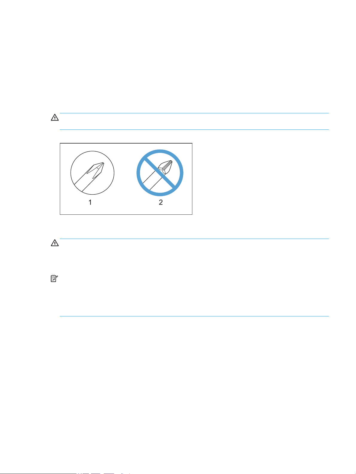
Required tools
● #2 Phillips screwdriver with a magnetic tip and a 152 mm (6 in) shaft length
● Small, at-blade screwdriver
● Needle-nose pliers
● ESD strap (if one is available)
● Penlight
CAUTION: Always use a Phillips screwdriver (callout 1). Do not use a Pozidriv screwdriver (callout 2) or any
motorized screwdriver. These can damage screws or screw threads.
Figure 1-1 Screwdrivers
Fasteners used in this printer
WARNING! Make sure that assemblies are replaced with the correct screw type. Using the incorrect screw (for
example, substituting a long screw for the correct shorter screw) can cause damage to the printer or interfere
with printer operation. Do not intermix screws that are removed from one assembly with the screws that are
removed from another assembly.
NOTE: To install a self-tapping screw, rst turn it counterclockwise to align it with the existing thread pattern,
and then carefully turn it clockwise to tighten. Do not overtighten. If a self-tapping screw hole becomes stripped,
repair the screw hole or replace the aected assembly.
Always take note of the length, diameter, color, type, and location of each removed screw. Make sure that
screws are installed in the original location they were removed from during reinstallation.
ENWW Removal and replacement strategy 5
Page 28

Service approach
Before performing service
● Remove all paper from the product.
● Turn o the power using the power switch.
● Unplug the power cable and interface cable or cables.
● Place the product on an ESD workstation or mat, or use an ESD strap (if one is available). If an ESD
workstation, mat, or strap is not available, ground yourself by touching the sheet-metal chassis before
touching an ESD-sensitive part.
● Remove the toner cartridge.
Accessing the secondary service menu
Use the secondary service menu to print service-related reports and run special tests.
NOTE: Access the secondary service menu by using the HP Embedded Web Server (EWS)
▲ Open the secondary service menu.
NOTE: HP Device Toolbox is software used to connect to the HP Embedded Web Server when the printer
is connected to a computer via USB. It is available only if a full installation was performed when the printer
was installed on a computer. Depending on how the printer is connected, some features might not be
available.
The HP Embedded Web Server is not accessible beyond the network rewall.
Open the HP EWS from the Start menu
a. Click the Start, and then click the Programs item.
b. Click your HP printer group, and then click the HP Device Toolbox item.
c. After opening the HP EWS, go to the Service page, and then select the Go to Secondary Service item.
Open the HP Embedded Web Server (EWS) from a Web browser
M14-M17 control panels: Select and hold the Resume button until the Ready light is blinking,
a.
and then release the Resume button. Find the IP address or host name of the printer on the
conguration report.
MFP M28-M311 LED control panels: Select and hold the Start Mono Copy button until the Ready
light begins blinking, and then release the Start Mono Copy button. Find the IP address or
host name of the printer on the conguration report.
6 Chapter 1 Removal and replacement ENWW
Page 29

b. Open a Web browser, and in the address line, type the IP address or host name exactly as it appears
on the printer control panel or the conguration report. Press the Enter key on the computer
keyboard. The EWS opens.
NOTE: If the web browser displays a message indicating that accessing the website might not be
safe, select the option to continue to the website. Accessing this website will not harm the computer.
c. After opening the HP EWS, go to the Service page, and then select the Go to Secondary Service item.
After performing service
1. Reinstall the toner cartridge.
2. Return all paper to the input tray.
3. Plug in the power cable and turn on the printer.
4. Perform print-quality tests by printing from a host computer.
Post-service tests
Perform the following tests to verify that the repair or replacement was successful.
Print-quality test
1. Verify that you have completed the necessary reassembly steps.
2. Make sure that the input tray contains clean, unmarked paper.
3. Attach the power cord and interface cable or interface cables, and then turn on the product.
4. Verify that the expected startup sounds occur.
5. Print a conguration page, and then verify that the expected printing sounds occur.
6. Send a print job from the host computer, and then verify that the output meets expectations.
Copy quality test (MFP only)
1. Verify that you have completed the necessary reassembly steps.
2. Make sure that the input tray contains clean, unmarked paper.
3. Attach the power cord and interface cable or interface cables, and then turn on the product.
4. Verify that the expected startup sounds occur.
5. Copy a conguration page (or other page), and then verify that the expected printing sounds occur.
6. Verify that the copy output meets expectations.
Other tests
Operate the printer in a manner that exercises the specic part or parts that have been repaired or replaced.
ENWW Service approach 7
Page 30

Order parts by authorized service providers
Ordering
Order supplies and paper www.hp.com/go/suresupply
Order genuine HP parts or accessories www.hp.com/buy/parts
or
partsurfer.hp.com
Order through service or support providers Contact an HP-authorized service or support provider.
Order using the HP Embedded Web Server (EWS) To access, in a supported Web browser on your computer, enter the printer IP
address or host name in the address/URL eld. The EWS contains a link to the HP
SureSupply Web site, which provides options for purchasing Original HP supplies.
Orderable parts
Not all parts can be ordered. Refer to the parts table following the exploded diagram in the parts chapter to
determine if a part is orderable.
Whole unit replacement (WUR)
HP LaserJet Pro model Whole unit replacement part number
HP LaserJet Pro M14-M17
220V M15A AP
220V M15A EMEA
220V M15w AP
220V M15w EMEA
110V M15w TW/NA
220V M15w LA
110V M15w LA
220V M16a China
220V M16a India
220V M16w India W2G53-67056
HP LaserJet Pro MFP M28-M34
220V M28a AP
220V M28a EMEA
220V M28w AP
W2G50-67056
W2G50-69056
W2G51-67056
W2G51-69056
W2G51-67055
W2G51-67019
W2G51-67020
W2G52-67056
W2G52-67001
W2G54-67056
WG54-69056
W2G55-67056
220V M28 EMEA
110V M28w TW/NA
110V M28w LA
W2G55-69058
W2G55-67055
W2G55-67020
8 Chapter 1 Removal and replacement ENWW
Page 31

HP LaserJet Pro model Whole unit replacement part number
220V M29a China
220V M29a India
220V M29w India W2G57–67056
W2G56-67056
W2G56-67001
ENWW Order parts by authorized service providers 9
Page 32

Supplies and accessories
Item Description Cartridge number Part number
Supplies
For use only in Europe, Russia, CIS, Mid East and Africa
HP 44A Black Toner Cartridge Standard-capacity replacement black toner
cartridge
For use only in North America, Latin America, Asia Pacic Countries/Regions (Exclude China, India)
HP 48A Black Toner Cartridge Standard-capacity replacement black toner
cartridge
For use only in China, India
HP 47A Black Toner Cartridge Standard-capacity replacement black toner
cartridge
Related documentation and software
HP service personnel, go to one of the following Web-based Interactive Search Engines (WISE) sites:
AMS
● https://support.hp.com/wise/home/ams-en
● https://support.hp.com/wise/home/ams-es
● https://support.hp.com/wise/home/ams-pt
APJ
44A CF244A
48A CF248A
47A CF247A
EMEA
● https://support.hp.com/wise/home/apj-en
● https://support.hp.com/wise/home/apj-ja
● https://support.hp.com/wise/home/apj-ko
● https://support.hp.com/wise/home/apj-zh-Hans
● https://support.hp.com/wise/home/apj-zh-Hant
● https://support.hp.com/wise/home/emea-en
Channel partners, go to HP Channel Services Network (CSN) at www.hp.com/partners/csn .
Channel partners, access training materials in the HP University and Partner Learning Center at
https://content.ext.hp.com/sites/LMS/HPU.page.
10 Chapter 1 Removal and replacement ENWW
Page 33

Removal and replacement procedures
Customer self-repair (CSR) components
The CSR level indicates the expected diculty the customer will experience when removing and replacing an
assembly. The CSR A assemblies in this section are easy for the customer to remove and replace.
●
Remove and replacement: Toner cartridge (M14-M17)
●
Remove and replacement: Toner cartridge (M28-M31)
ENWW Removal and replacement procedures 11
Page 34

Remove and replacement: Toner cartridge (M14-M17)
●
Introduction
●
Step 1: Remove the toner cartridge
●
Step 2: Unpack a replacement toner cartridge
●
Step 3: Install the toner cartridge
Introduction
This document provides the procedures to remove and replace the toner cartridge.
IMPORTANT: When applicable, special installation instructions are provided for an assembly at the end of the
removal procedure. Always completely read the removal instructions and follow all special installation
instructions.
Before performing service
● Turn the printer power o.
CAUTION: To prevent damage to the toner cartridge, do not expose it to light for more than a few minutes.
Cover the toner cartridge if it must be removed from the printer for an extended period of time.
If toner gets on clothing, wipe it o by using a dry cloth and wash the clothes in cold water. Hot water sets toner
into fabric.
Use the table below to identify the correct part number for your printer. To order the part, go to
www.hp.com/buy/parts
Toner cartridge part numbers
M14-M17 Europe, Russia, CIS, Middle East, and Africa only:
CF244A (new)
CF244-67901 (service)
M14-M17 North America, Latin America, Asia Pacic Countries/Regions (excluding China and India) only:
CF248A (new)
CF248-67901 (service)
M14-M17 China and India only:
CF247A (new)
CF247-67901 (service)
Required tools
● No special tools are needed to remove or install this assembly.
HP 44A Black Toner Cartridge
HP 48A Black Toner Cartridge
HP 47A Black Toner Cartridge
After performing service
● Make sure that the cartridge door is fully closed after replacing the toner cartridge.
● Turn the printer power on.
12 Chapter 1 Removal and replacement ENWW
Page 35
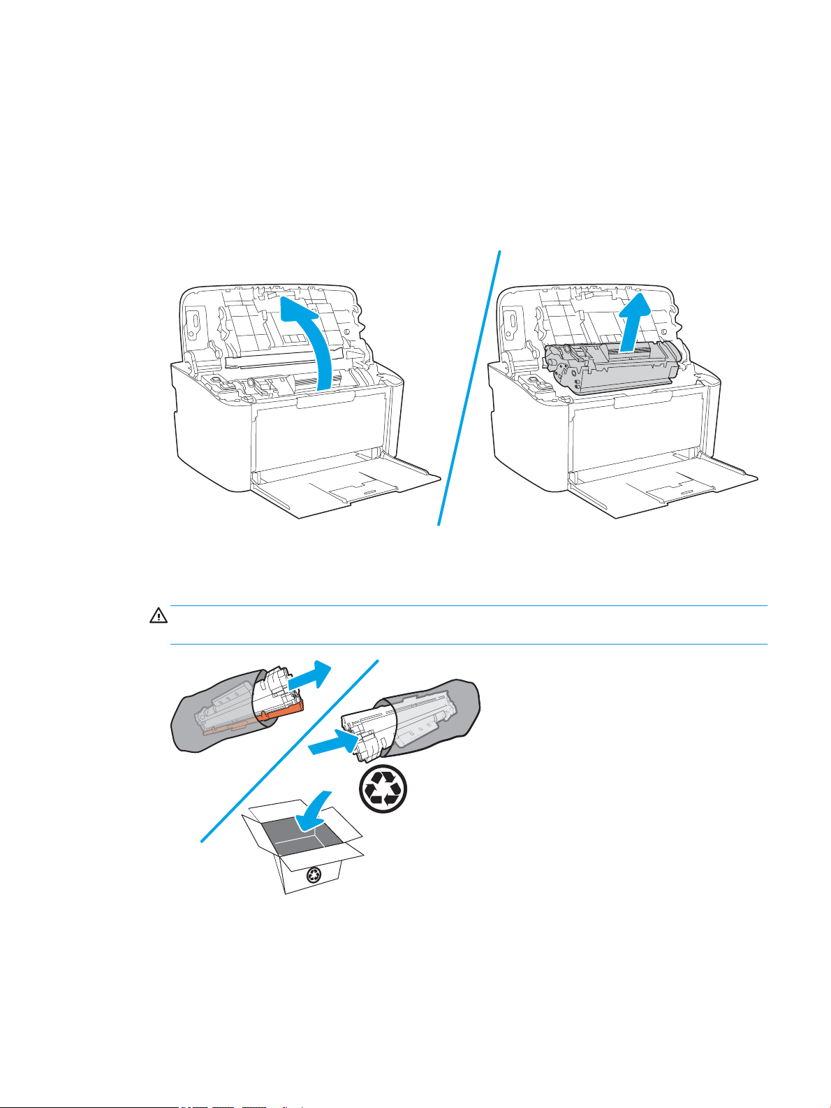
Post service test
No post service test is available for this assembly.
Step 1: Remove the toner cartridge
When a toner cartridge approaches the end of useful life, continue printing with the current cartridge until
redistributing the toner no longer yields acceptable print quality.
▲ Open the toner-cartridge door, and then remove the old toner cartridge.
Step 2: Unpack a replacement toner cartridge
1. Remove the new toner cartridge packaging. Place the used toner cartridge in the bag and box for recycling.
CAUTION: To prevent damage to the toner cartridge, hold it by both ends. Do not touch the OPC cover or
roller surface.
ENWW Removal and replacement procedures 13
Page 36
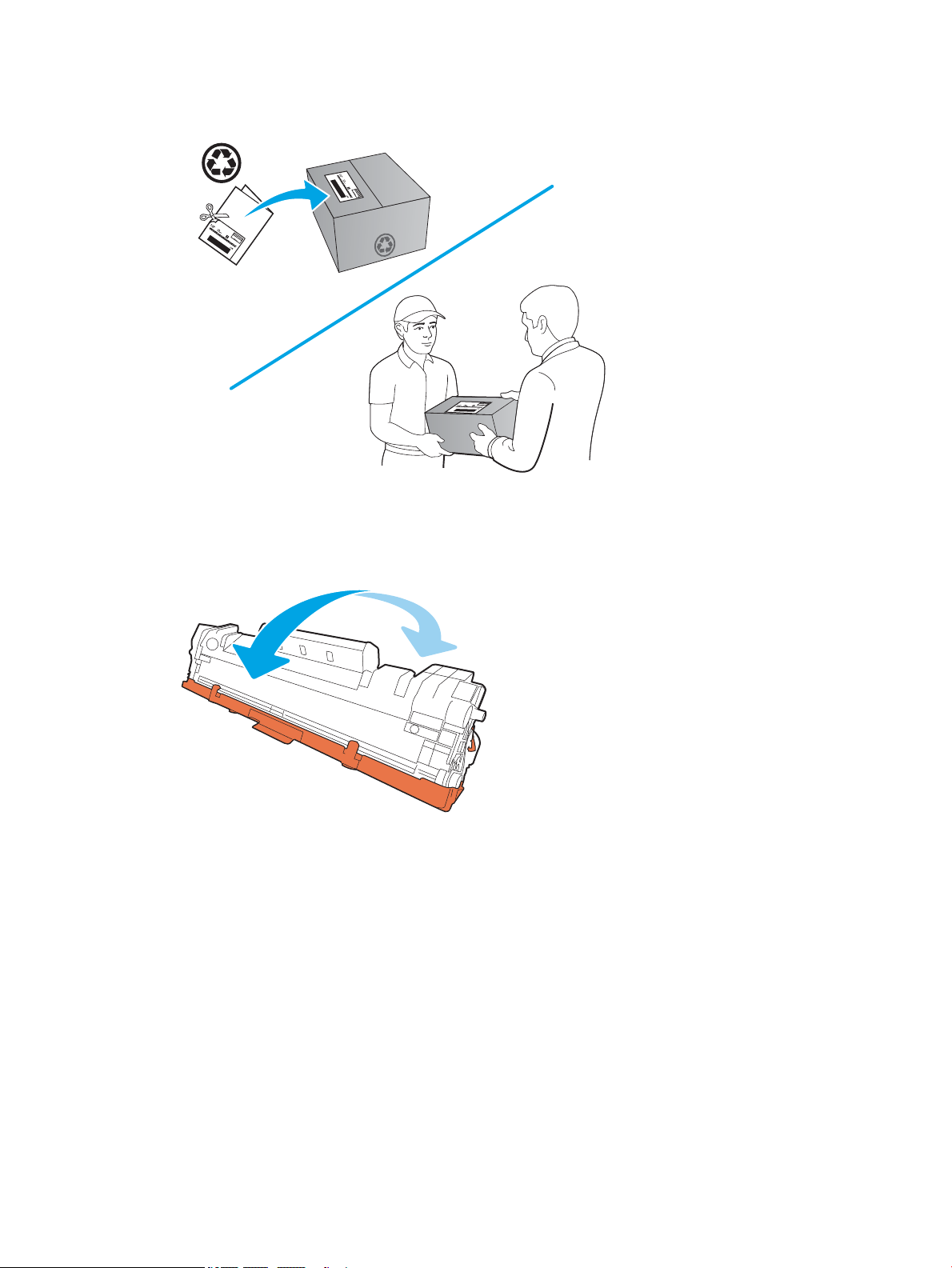
2. Use the pre-paid self-addressed label to return the used cartridge to HP for recycling (where available).
Step 3: Install the toner cartridge
1. Grasp both sides of the toner cartridge and gently rock the toner cartridge to distribute the toner evenly
inside the cartridge.
14 Chapter 1 Removal and replacement ENWW
Page 37
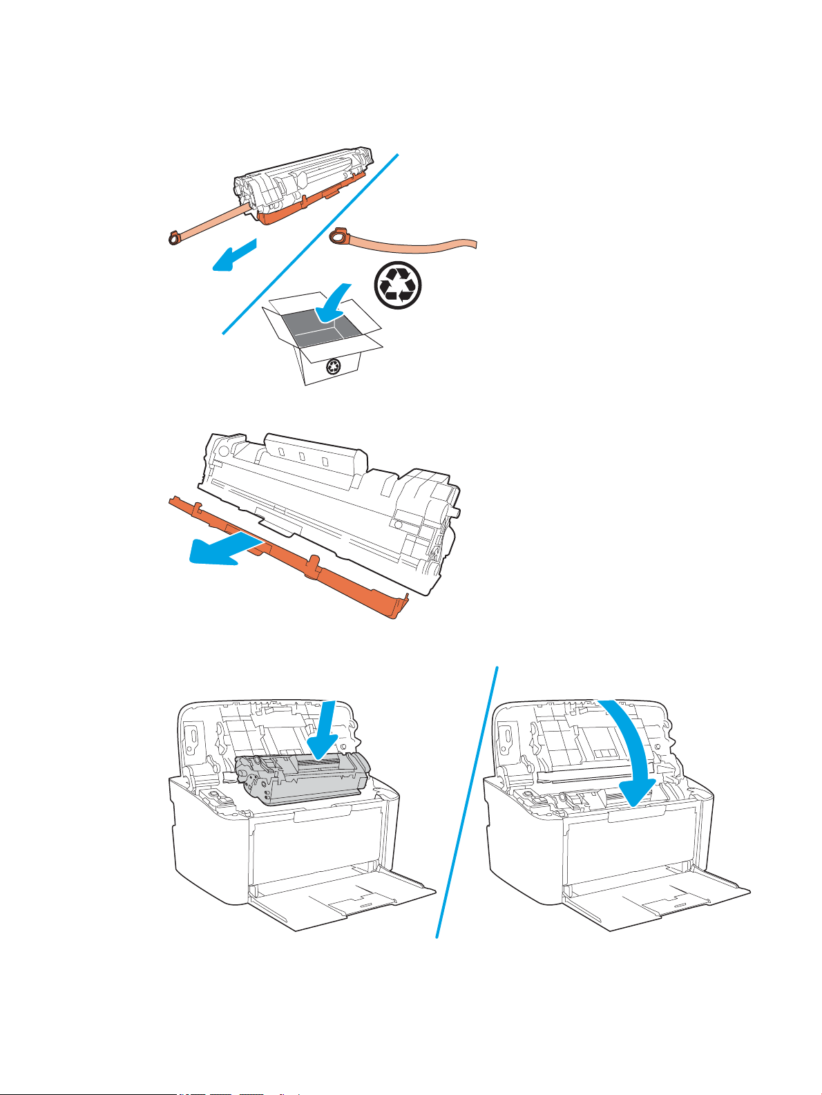
2. Bend the tab on the left side of the cartridge until the tab breaks loose, and then pull the tab until all the
tape is removed from the cartridge. Place the tab and tape in the toner-cartridge box to return for
recycling.
3. Remove the orange cover from the toner cartridge.
4. Insert the toner cartridge in the printer, and then close the toner-cartridge door.
ENWW Removal and replacement procedures 15
Page 38

Remove and replacement: Toner cartridge (M28-M31)
●
Introduction
●
Step 1: Remove the toner cartridge
●
Step 2: Unpack a replacement toner cartridge
●
Step 3: Install the toner cartridge
Introduction
This document provides the procedures to remove and replace the toner cartridge.
IMPORTANT: When applicable, special installation instructions are provided for an assembly at the end of the
removal procedure. Always completely read the removal instructions and follow all special installation
instructions.
Before performing service
● Turn the printer power o.
CAUTION: To prevent damage to the toner cartridge, do not expose it to light for more than a few minutes.
Cover the toner cartridge if it must be removed from the printer for an extended period of time.
If toner gets on clothing, wipe it o by using a dry cloth and wash the clothes in cold water. Hot water sets toner
into fabric.
Use the table below to identify the correct part number for your printer. To order the part, go to
www.hp.com/buy/parts
Toner cartridge part numbers
M28-M31 Europe, Russia, CIS, Middle East, and Africa only:
CF244A (new)
CF244-67901 (service)
M28-M31 North America, Latin America, Asia Pacic Countries/Regions (excluding China and India) only:
CF248A (new)
CF248-67901 (service)
M28-M31 China and India only:
CF247A (new)
CF247-67901 (service)
Required tools
● No special tools are needed to remove or install this assembly.
HP 44A Black Toner Cartridge
HP 48A Black Toner Cartridge
HP 47A Black Toner Cartridge
After performing service
● Make sure that the cartridge door is fully closed after replacing the toner cartridge.
● Turn the printer power on.
16 Chapter 1 Removal and replacement ENWW
Page 39
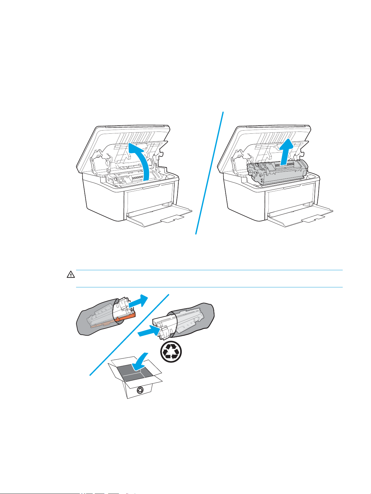
Post service test
No post service test is available for this assembly.
Step 1: Remove the toner cartridge
When a toner cartridge approaches the end of useful life, continue printing with the current cartridge until
redistributing the toner no longer yields acceptable print quality.
▲ Open the toner-cartridge door, and then remove the old toner cartridge.
Step 2: Unpack a replacement toner cartridge
1. Remove the new toner cartridge packaging. Place the used toner cartridge in the bag and box for recycling.
CAUTION: To prevent damage to the toner cartridge, hold it by both ends. Do not touch the OPC cover or
roller surface.
ENWW Removal and replacement procedures 17
Page 40
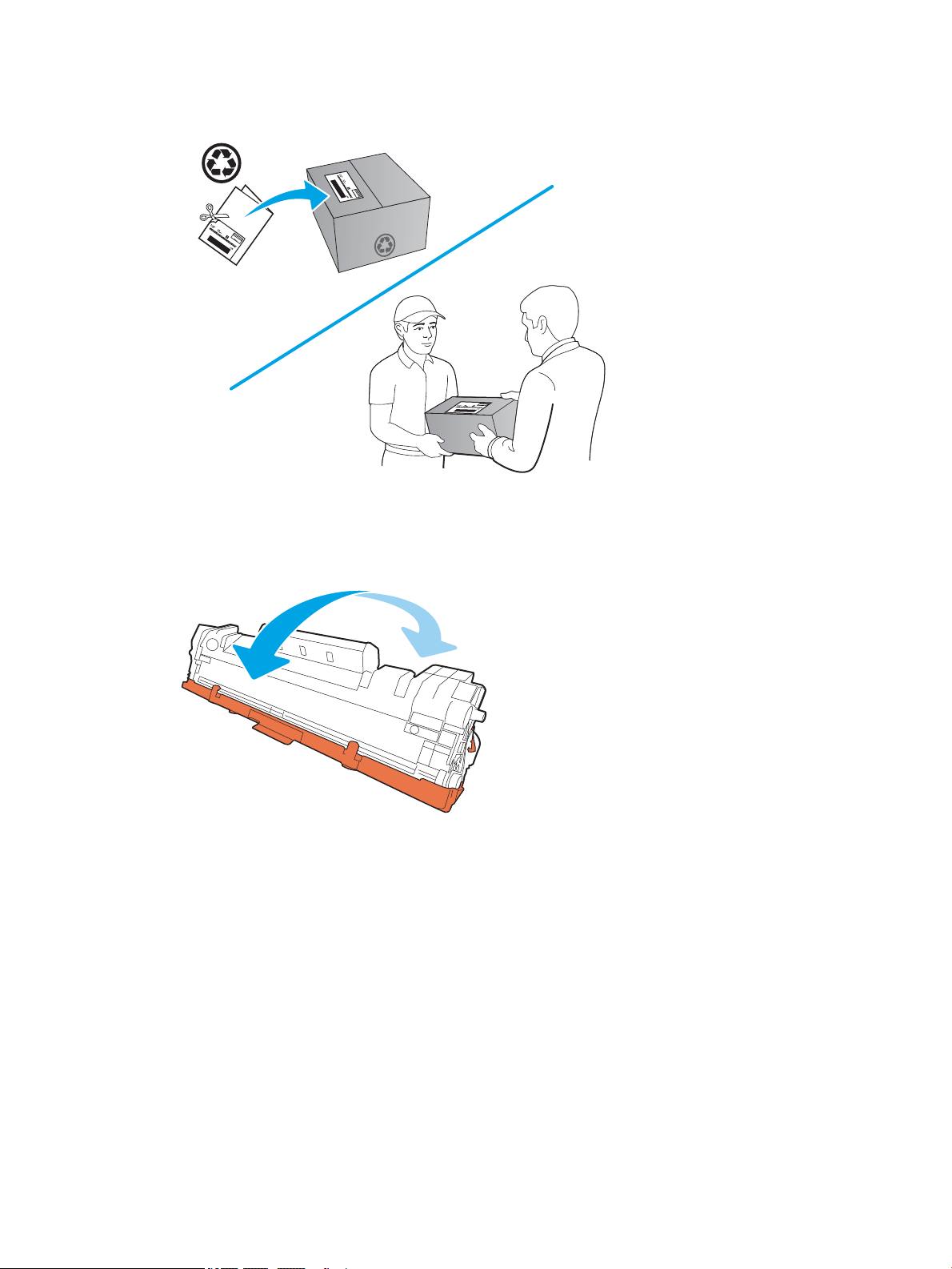
2. Use the pre-paid self-addressed label to return the used cartridge to HP for recycling (where available).
Step 3: Install the toner cartridge
1. Grasp both sides of the toner cartridge and gently rock the toner cartridge to distribute the toner evenly
inside the cartridge.
18 Chapter 1 Removal and replacement ENWW
Page 41
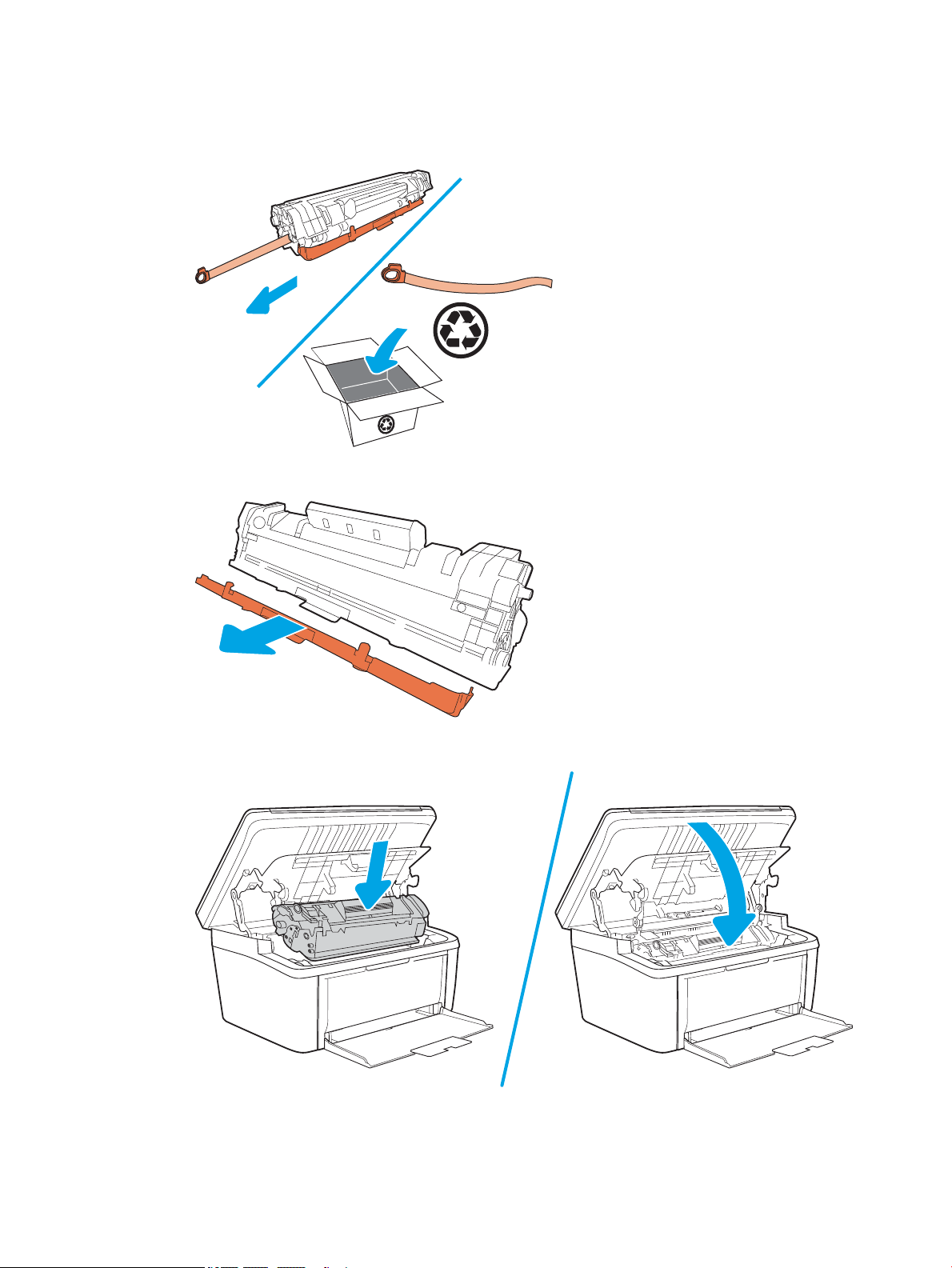
2. Bend the tab on the left side of the cartridge until the tab breaks loose, and then pull the tab until all the
tape is removed from the cartridge. Place the tab and tape in the toner-cartridge box to return for
recycling.
3. Remove the orange cover from the toner cartridge.
4. Insert the toner cartridge in the printer, and then close the toner-cartridge door.
ENWW Removal and replacement procedures 19
Page 42

Field Replaceable Units (FRUs) / Bench Repair Units (BRUs)
●
Removal and replacement: External panels, covers, and doors
●
Removal and replacement: Internal parts and assemblies
20 Chapter 1 Removal and replacement ENWW
Page 43

Removal and replacement: External panels, covers, and doors
●
Remove and replacement: Tray 1
●
Remove and replacement: Cartridge door (M14-M17)
●
Remove and replacement: Document lid (M28-M31)
●
Remove and replacement: Formatter cover (M14-M17)
●
Remove and replacement: Formatter cover (MFP M28-M31)
●
Remove and replacement: Cartridge door (MFP M28-M31)
●
Remove and replacement: Image scanner (MFP M28-M31)
●
Remove and replacement: Lower cover (M14-M17)
●
Remove and replacement: Lower cover (MFP M28-M31)
●
Remove and replacement: Top cover (MFP M28-M31)
●
Remove and replacement: Control panel (M14-M17)
ENWW Removal and replacement procedures 21
Page 44

Remove and replacement: Tray 1
●
Introduction
●
Step 1: Remove Tray 1
●
Step 2: Unpack the replacement assembly
Introduction
This document provides the procedures to remove and replace Tray 1.
IMPORTANT: When applicable, special installation instructions are provided for an assembly at the end of the
removal procedure. Always completely read the removal instructions and follow all special installation
instructions.
Before performing service
● Turn the printer power o.
Use the table below to identify the correct part number for your printer. To order the part, go to
www.hp.com/buy/parts
Tray 1 part number
RL2-2589-000CN Tray, paper pickup (base model; M14-M17)
RL2-2590-000CN Tray, paper pickup (wireless model; M14-M17)
RL2-2591-000CN Tray, paper pickup (base EM model; M14-M17)
RL2-2592-000CN Tray, paper pickup (wireless EM model; M14-M17)
RL2-2594-000CN Tray, paper pickup (base model; M28-M31)
RL2-2595-000CN Tray, paper pickup (wireless model; M28-M31)
RL2-2596-000CN Tray, paper pickup (base EM model; M28-M31)
RL2-2597-000CN Tray, paper pickup (wireless EM model; M28-M31)
Required tools
● No special tools are needed to remove or install this assembly.
After performing service
● Turn the printer power on.
Post service test
No post service test is available for this assembly.
Step 1: Remove Tray 1
▲ Open Tray 1, gently ex the tray to release two bosses (callout 1), and then remove Tray 1 (callout 2).
Reinstallation tip: Reverse the removal steps to install the assembly.
22 Chapter 1 Removal and replacement ENWW
Page 45
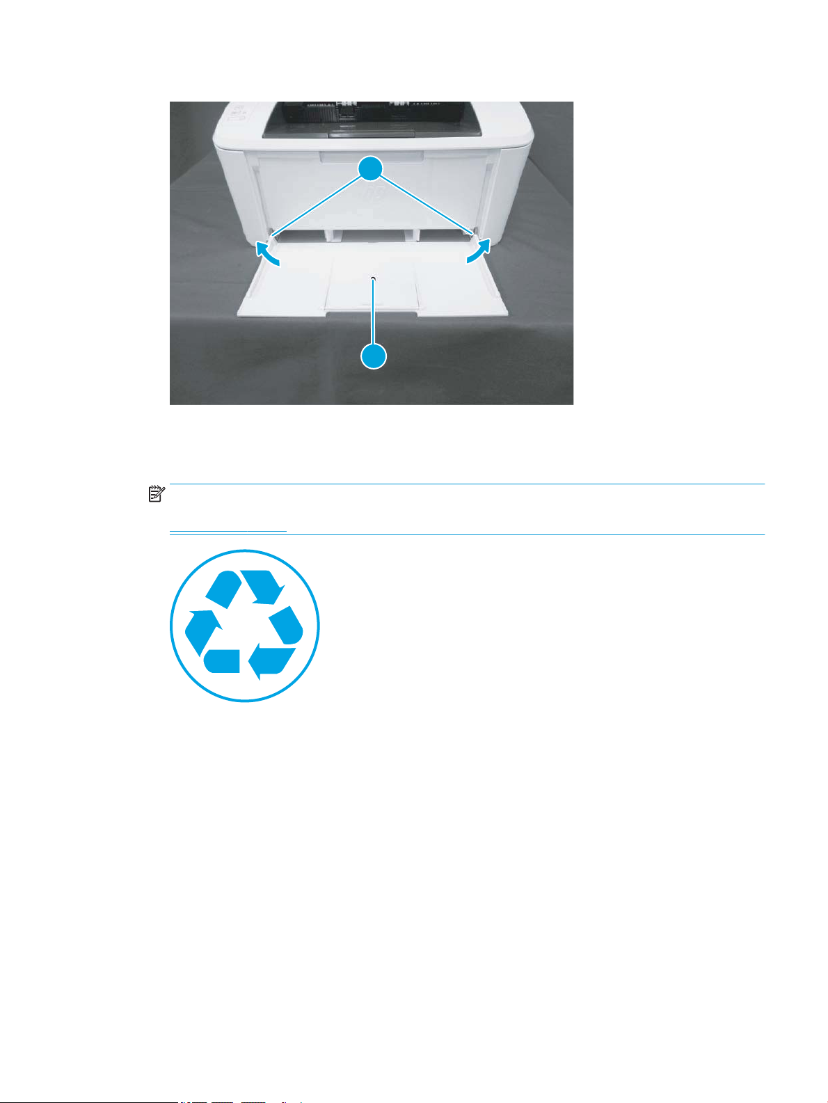
Figure 1-2 Remove Tray 1
1
2
Step 2: Unpack the replacement assembly
1. Dispose of the defective part.
NOTE: HP recommends responsible disposal of the defective part.
www.hp.com/recycle
ENWW Removal and replacement procedures 23
Page 46
2. Unpack the replacement part from the packaging.
CAUTION: If the replacement part is a roller or pad, avoid touching the spongy part of it. Skin oils on the
roller or pad can cause paper pickup and/or print-quality problems. HP recommends using disposable
gloves when handling rollers or pads or washing your hands or before touching rollers or pads.
IMPORTANT: Make sure that all of the shipping materials (for example shipping tape) are removed from
the replacement part prior to installation.
24 Chapter 1 Removal and replacement ENWW
Page 47

Remove and replacement: Cartridge door (M14-M17)
●
Introduction
●
Step 1: Remove the cartridge door (M14-M17)
●
Step 2: Unpack the replacement assembly
Introduction
This document provides the procedures to remove and replace the cartridge door (M14-M17).
IMPORTANT: When applicable, special installation instructions are provided for an assembly at the end of the
removal procedure. Always completely read the removal instructions and follow all special installation
instructions.
Before performing service
● Turn the printer power o.
Use the table below to identify the correct part number for your printer. To order the part, go to
www.hp.com/buy/parts
Cartridge door (M14-M17) part number
RM2-2118-000CN
RM2-2119-000CN
Required tools
● #2 Phillips screwdriver with a magnetic tip
● Small at-blade screw driver (optional)
After performing service
● Make sure that the cartridge door is fully closed after replacing it.
● Turn the printer power on.
Post service test
No post service test is available for this assembly.
Step 1: Remove the cartridge door (M14-M17)
1. Open the cartridge door, and then remove two screws (callout 1).
Cartridge door (base model; M14–M17)
Cartridge door (wireless model; M14–M17)
ENWW Removal and replacement procedures 25
Page 48
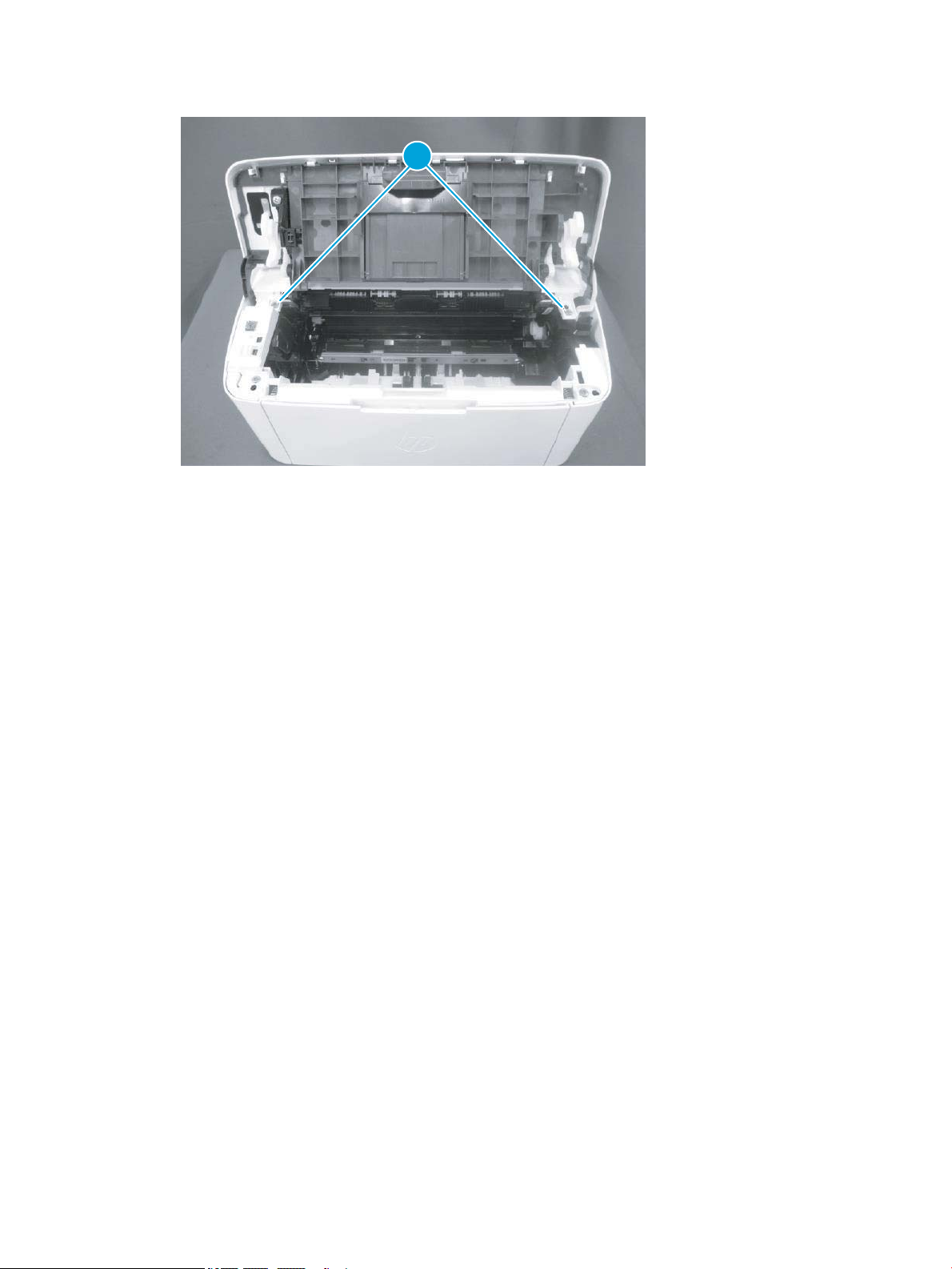
Figure 1-3 Remove two screw
1
26 Chapter 1 Removal and replacement ENWW
Page 49
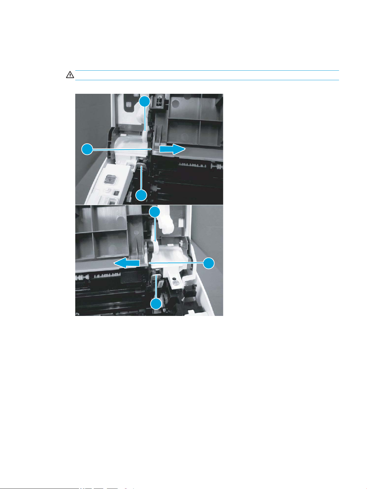
2. Before proceeding, take note of the following disassembly instructions.
1
2
3
3
2
1
When removing the link arm (callout 2) from the pressure release lever (callout 1), the pressure plate
(callout 3) might be deformed if the pressure release lever moves in the direction shown below.
CAUTION: Do not deform the pressure plate.
Figure 1-4 Special disassembly instructions
ENWW Removal and replacement procedures 27
Page 50
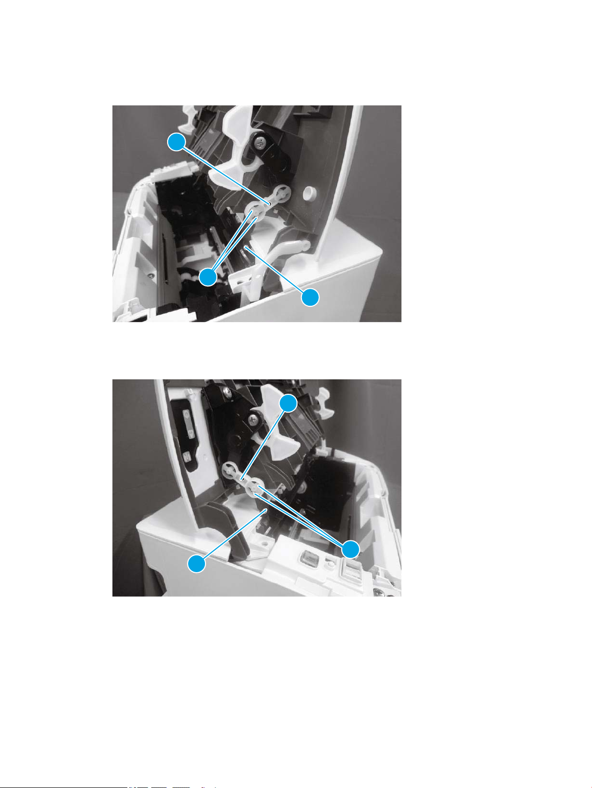
3. Release two tabs (callout 1), and then remove one link arm (callout 3) from the pressure release lever
3
2
1
3
2
1
(callout 2).
Figure 1-5 Remove the link arm
4. Release two tabs (callout 1), and then remove one link arm (callout 3) from the pressure release lever
(callout 2).
Figure 1-6 Remove the link arm
28 Chapter 1 Removal and replacement ENWW
Page 51
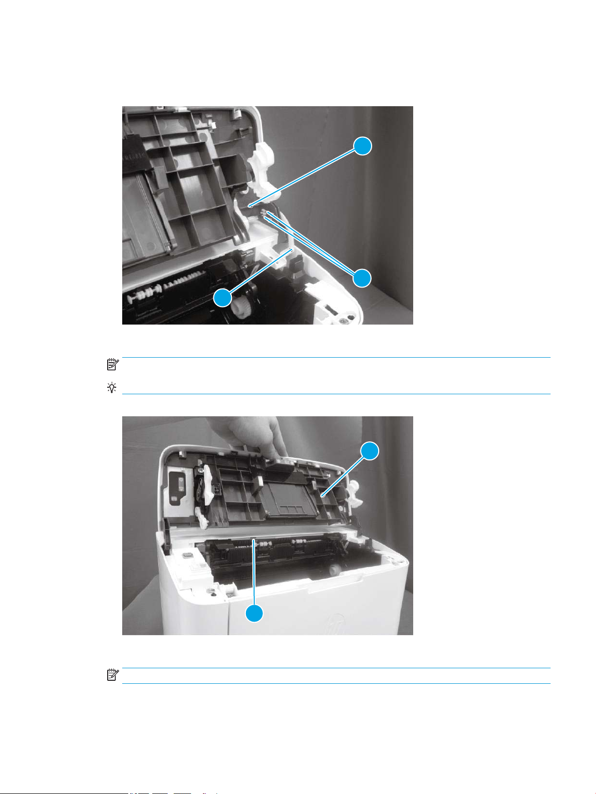
5. Release two tabs (callout 1), and then remove one link arm (callout 3) from the cartridge door assembly
2
3
1
1
2
(callout 2).
Figure 1-7 Remove the link arm
6. Release one tab (callout 1), support the cartridge door (callout 2), and then remove it.
NOTE: If the cartridge door is removed to access other assembly, stop at this step.
Reinstallation tip: Reverse the removal steps to install the door.
Figure 1-8 Remove the cartridge door
7. Optional step: If a replacement cartridge door is being installed, do the following:
NOTE: Install the link arms on the replacement door.
a. Release two tabs (callout 1), and then remove the one link arm (callout 3) from the door assembly
(callout 2).
ENWW Removal and replacement procedures 29
Page 52
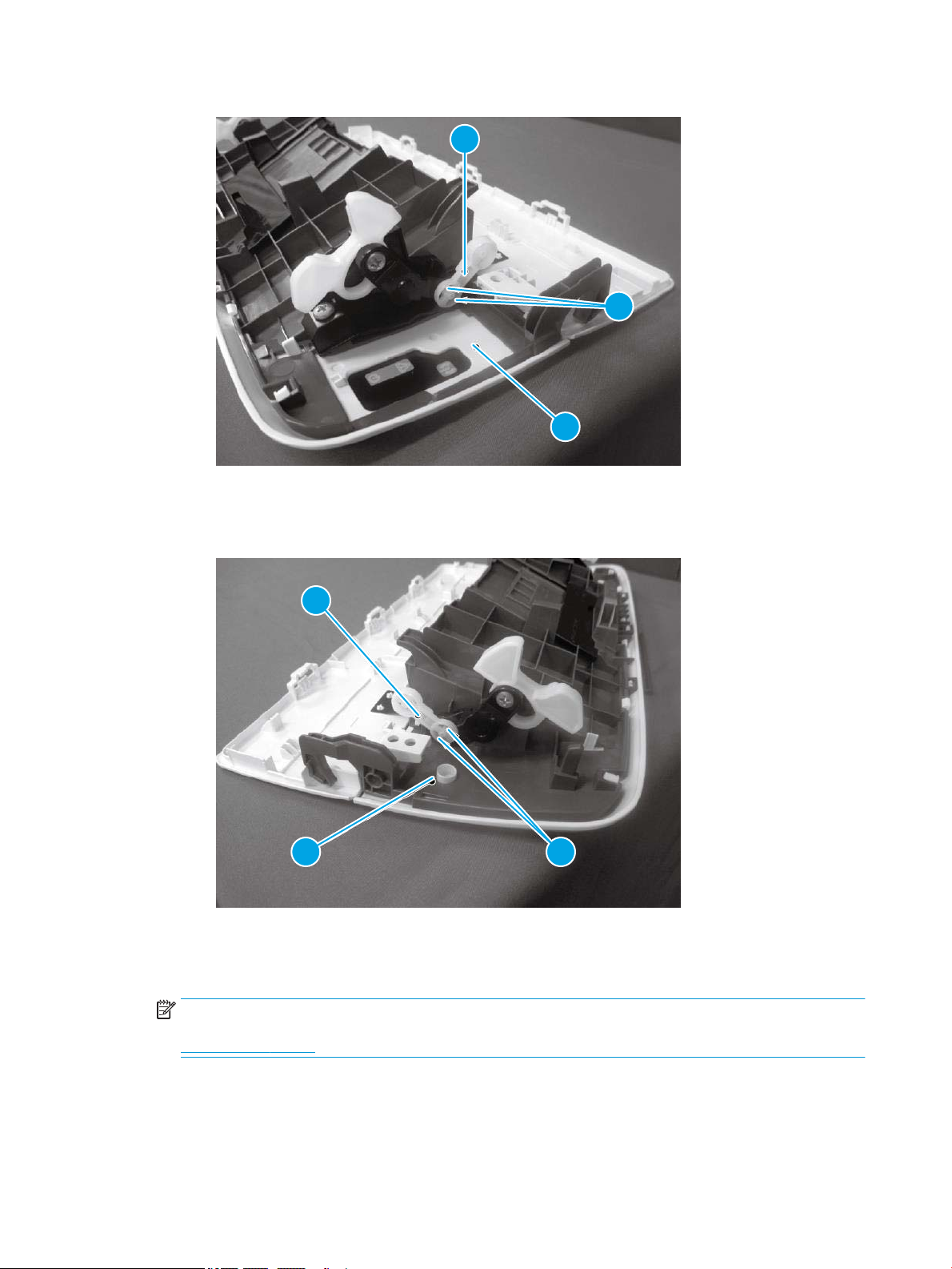
Figure 1-9 Install the link arms on the replacement door
3
2
1
3
2 1
b. Release two tabs (callout 1), and then remove the one link arm (callout 3) from the door assembly
(callout 2).
Figure 1-10 Install the link arms on the replacement door
Step 2: Unpack the replacement assembly
1. Dispose of the defective part.
NOTE: HP recommends responsible disposal of the defective part.
www.hp.com/recycle
30 Chapter 1 Removal and replacement ENWW
Page 53
2. Unpack the replacement part from the packaging.
CAUTION: If the replacement part is a roller or pad, avoid touching the spongy part of it. Skin oils on the
roller or pad can cause paper pickup and/or print-quality problems. HP recommends using disposable
gloves when handling rollers or pads or washing your hands or before touching rollers or pads.
IMPORTANT: Make sure that all of the shipping materials (for example shipping tape) are removed from
the replacement part prior to installation.
ENWW Removal and replacement procedures 31
Page 54

Remove and replacement: Document lid (M28-M31)
●
Introduction
●
Step 1: Remove the document lid (M28-M31)
●
Step 2: Unpack the replacement assembly
Introduction
This document provides the procedures to remove and replace the document lid (M28-M31).
IMPORTANT: When applicable, special installation instructions are provided for an assembly at the end of the
removal procedure. Always completely read the removal instructions and follow all special installation
instructions.
Before performing service
● Turn the printer power o.
Use the table below to identify the correct part number for your printer. To order the part, go to
www.hp.com/buy/parts
Document lid (M28-M31) part number
RM2-2136-000CN Document lid (M28-M31)
Required tools
● No special tools are needed to remove or install this assembly.
After performing service
● Make sure that the document lid is fully closed after replacing it.
● Turn the printer power on.
Post service test
No post service test is available for this assembly.
Step 1: Remove the document lid (M28-M31)
▲ Do the following:
● Open the document lid.
● Press and hold one tab (callout 1), and then slide the document lid (callout 2) as shown below to
remove it.
32 Chapter 1 Removal and replacement ENWW
Page 55
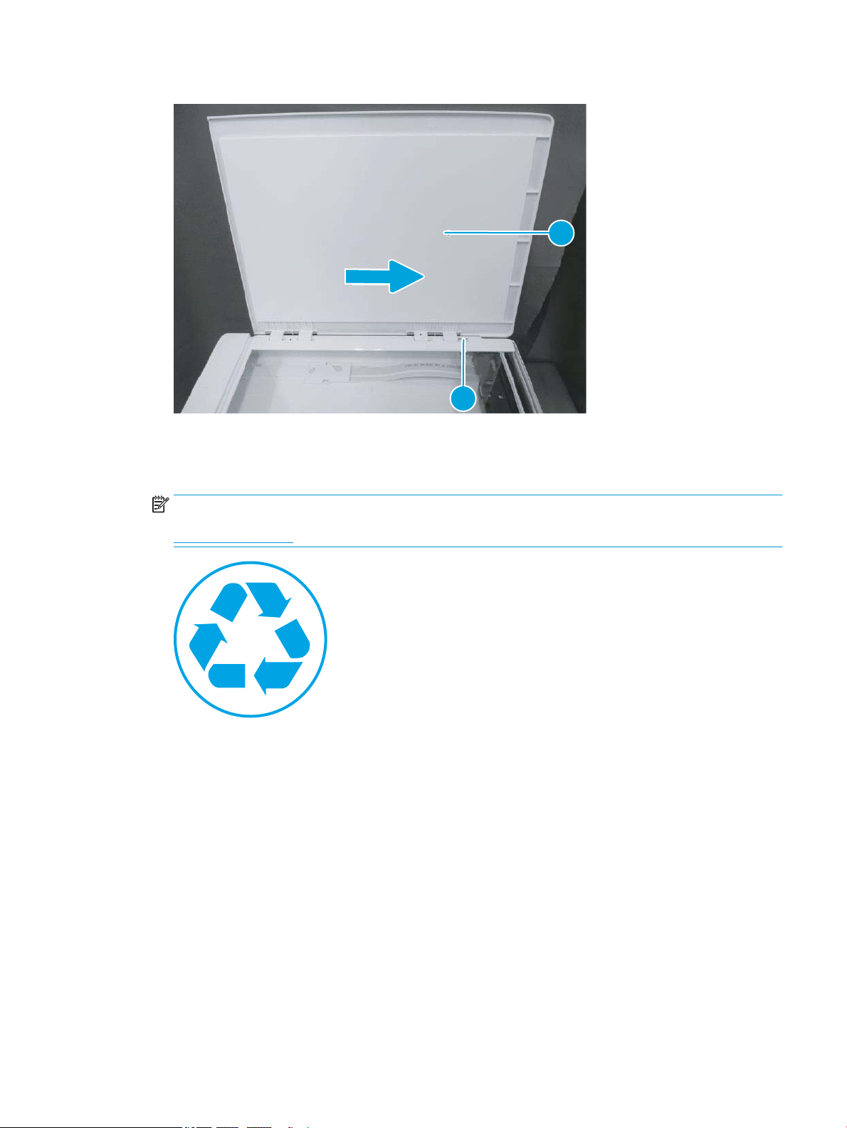
Figure 1-11 Remove the document lid (M28-M31)
1
2
Step 2: Unpack the replacement assembly
1. Dispose of the defective part.
NOTE: HP recommends responsible disposal of the defective part.
www.hp.com/recycle
ENWW Removal and replacement procedures 33
Page 56
2. Unpack the replacement part from the packaging.
CAUTION: If the replacement part is a roller or pad, avoid touching the spongy part of it. Skin oils on the
roller or pad can cause paper pickup and/or print-quality problems. HP recommends using disposable
gloves when handling rollers or pads or washing your hands or before touching rollers or pads.
IMPORTANT: Make sure that all of the shipping materials (for example shipping tape) are removed from
the replacement part prior to installation.
34 Chapter 1 Removal and replacement ENWW
Page 57

Remove and replacement: Formatter cover (M14-M17)
●
Introduction
●
Step 1: Remove the cartridge door (M14-M17)
●
Step 2: Remove the formatter cover (M14-M17)
●
Step 3: Unpack the replacement assembly
Introduction
This document provides the procedures to remove and replace the formatter cover (M14-M17).
IMPORTANT: When applicable, special installation instructions are provided for an assembly at the end of the
removal procedure. Always completely read the removal instructions and follow all special installation
instructions.
Before performing service
● Turn the printer power o.
Use the table below to identify the correct part number for your printer. To order the part, go to
www.hp.com/buy/parts
Formatter cover (M14-M17) part number
RC5-4239-000CN Formatter cover (M14-M17)
Required tools
● No special tools are needed to remove or install this assembly.
After performing service
● Turn the printer power on.
Post service test
No post service test is available for this assembly.
Step 1: Remove the cartridge door (M14-M17)
1. Open the cartridge door, and then remove two screws (callout 1).
ENWW Removal and replacement procedures 35
Page 58
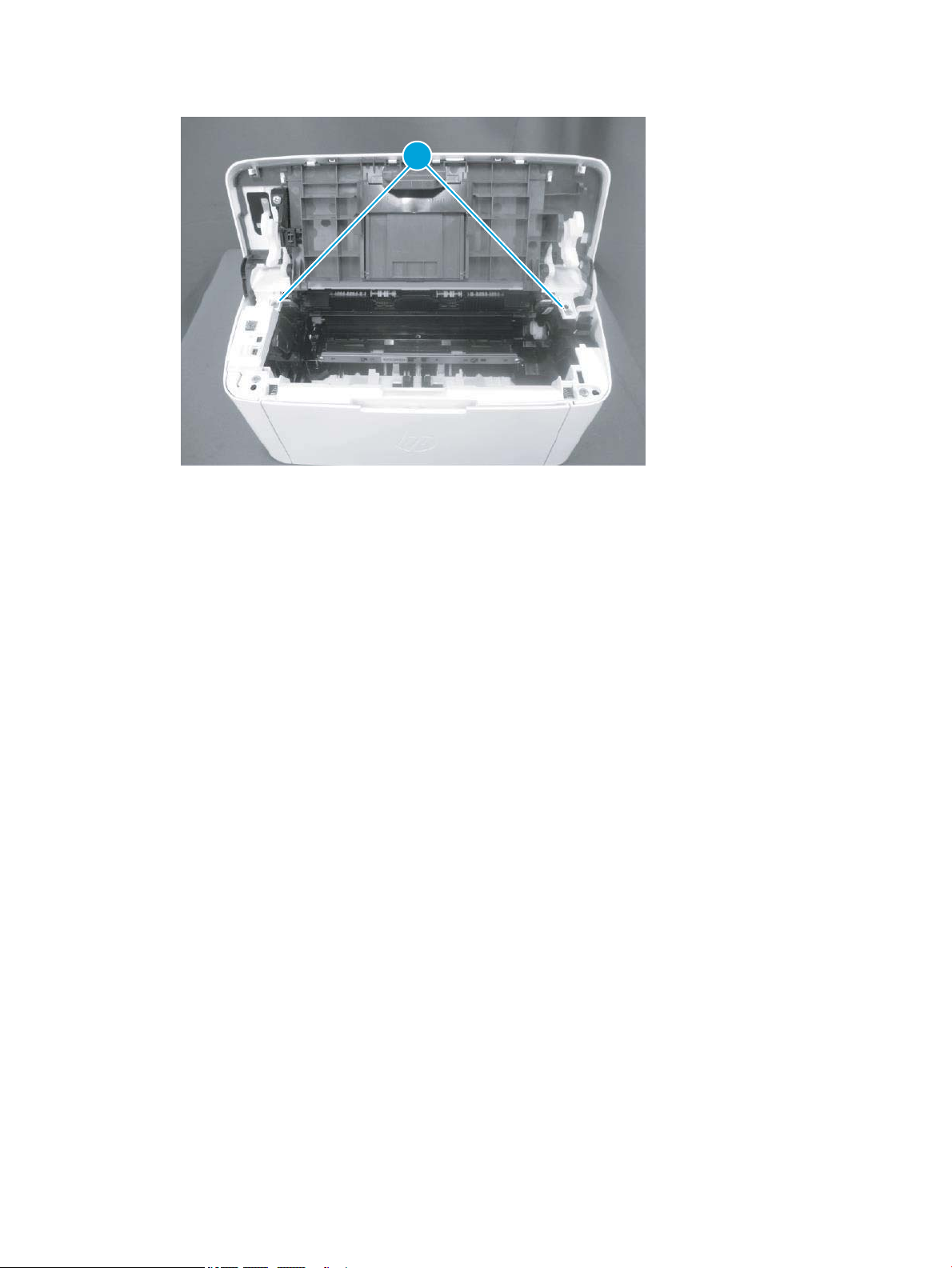
Figure 1-12 Remove two screw
1
36 Chapter 1 Removal and replacement ENWW
Page 59
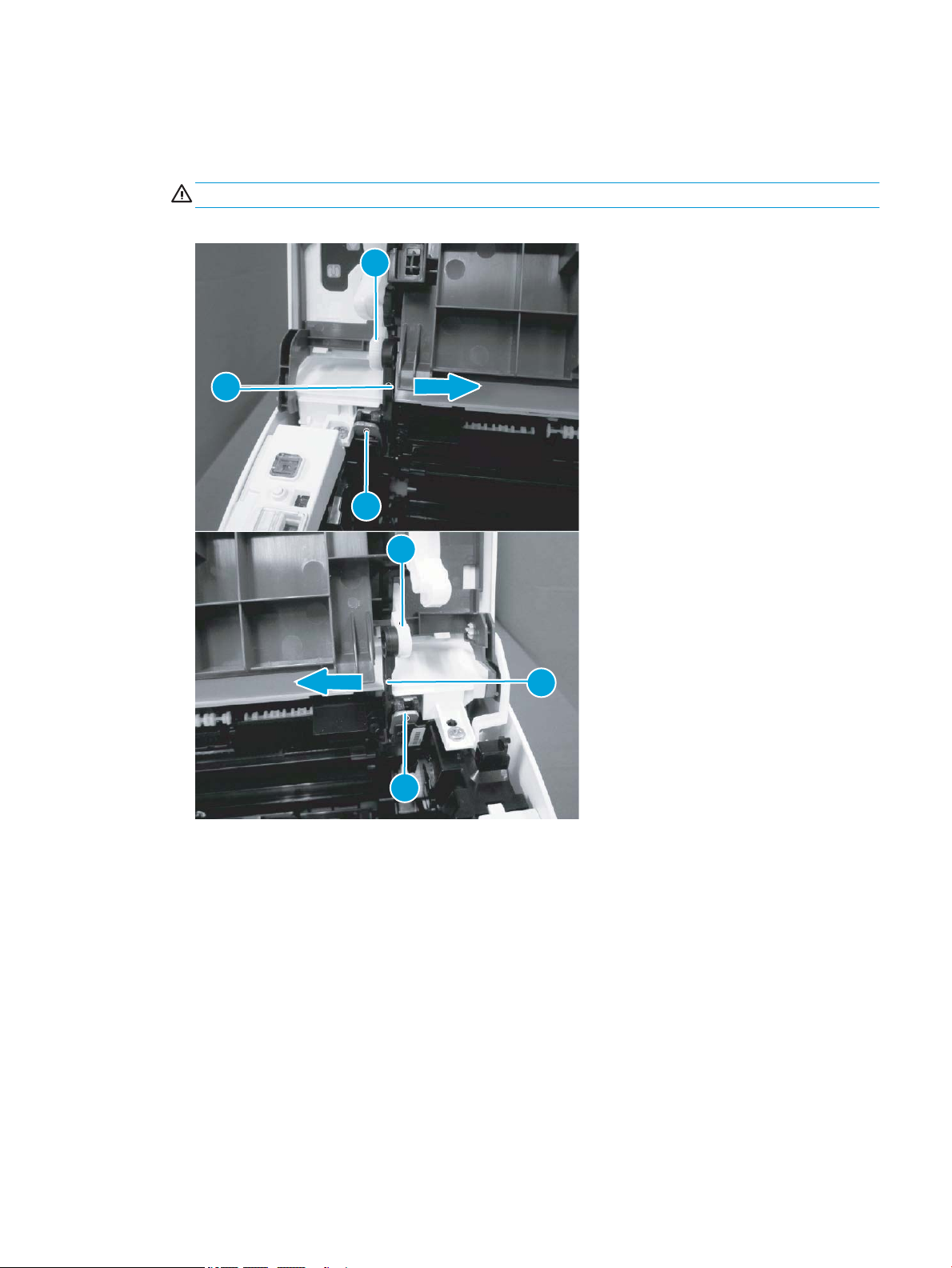
2. Before proceeding, take note of the following disassembly instructions.
1
2
3
3
2
1
When removing the link arm (callout 2) from the pressure release lever (callout 1), the pressure plate
(callout 3) might be deformed if the pressure release lever moves in the direction shown below.
CAUTION: Do not deform the pressure plate.
Figure 1-13 Special disassembly instructions
ENWW Removal and replacement procedures 37
Page 60
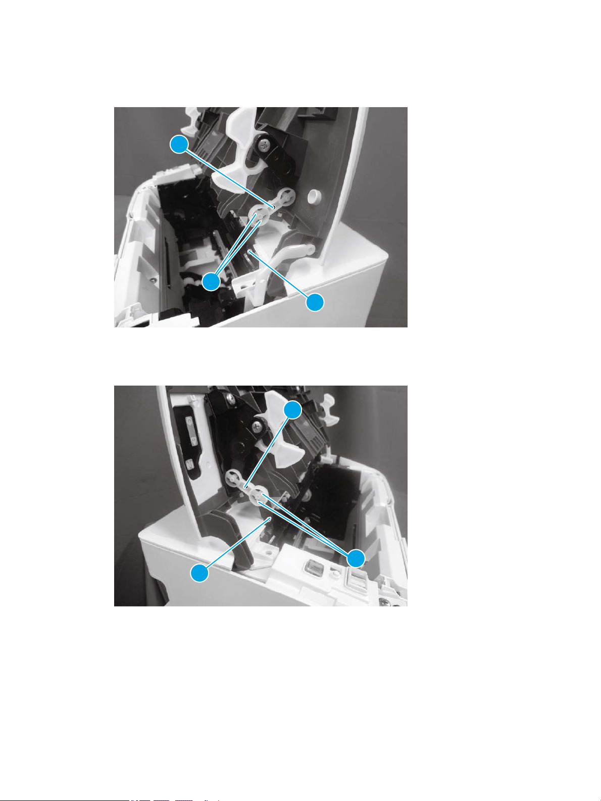
3. Release two tabs (callout 1), and then remove one link arm (callout 3) from the pressure release lever
3
2
1
3
2
1
(callout 2).
Figure 1-14 Remove the link arm
4. Release two tabs (callout 1), and then remove one link arm (callout 3) from the pressure release lever
(callout 2).
Figure 1-15 Remove the link arm
38 Chapter 1 Removal and replacement ENWW
Page 61
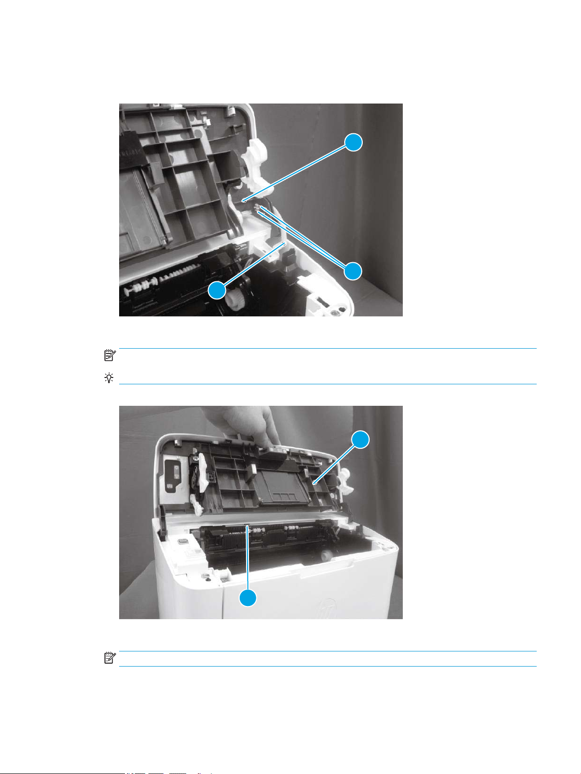
5. Release two tabs (callout 1), and then remove one link arm (callout 3) from the cartridge door assembly
2
3
1
1
2
(callout 2).
Figure 1-16 Remove the link arm
6. Release one tab (callout 1), support the cartridge door (callout 2), and then remove it.
NOTE: If the cartridge door is removed to access other assembly, stop at this step.
Reinstallation tip: Reverse the removal steps to install the door.
Figure 1-17 Remove the cartridge door
7. Optional step: If a replacement cartridge door is being installed, do the following:
NOTE: Install the link arms on the replacement door.
a. Release two tabs (callout 1), and then remove the one link arm (callout 3) from the door assembly
(callout 2).
ENWW Removal and replacement procedures 39
Page 62
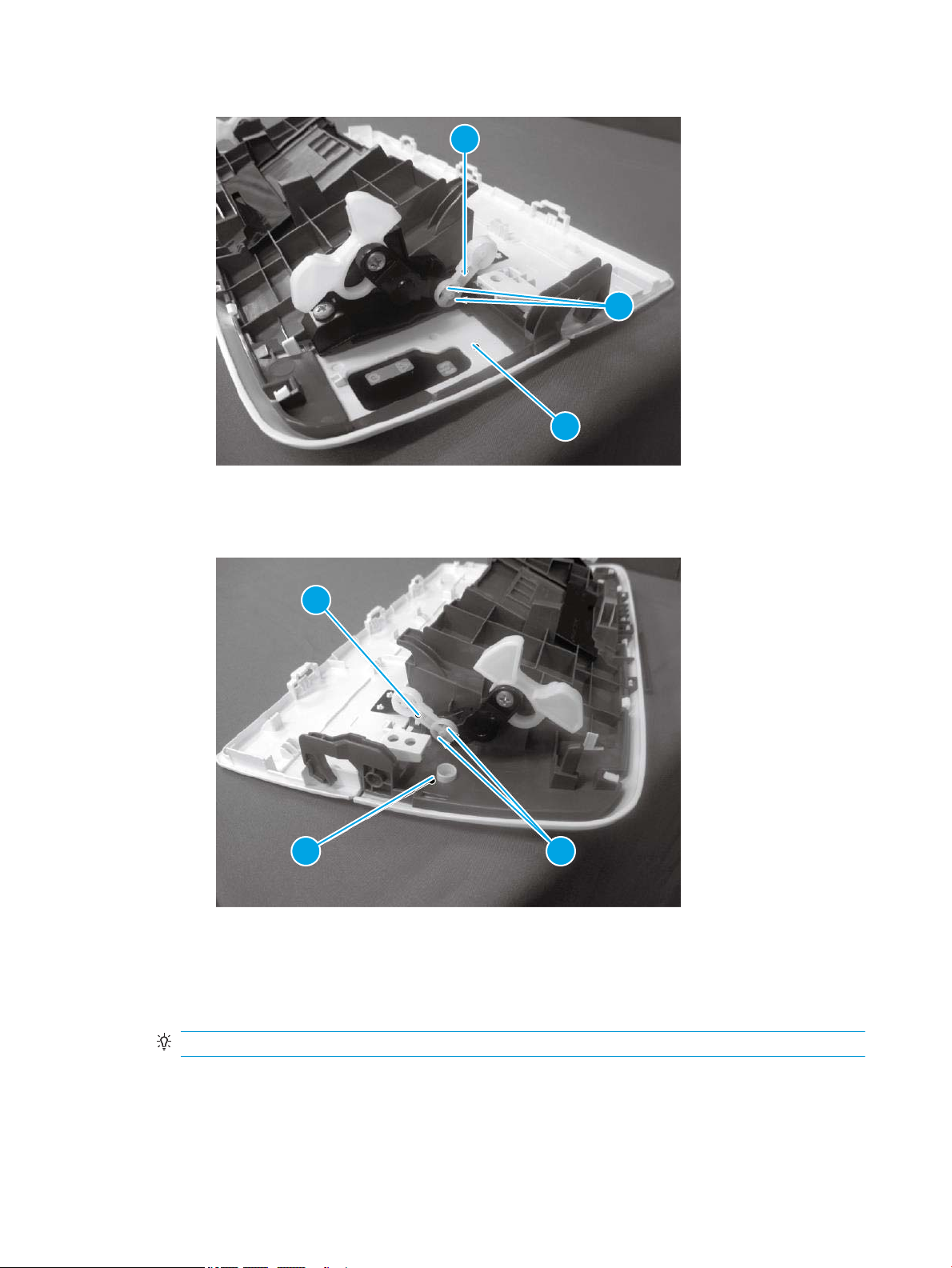
Figure 1-18 Install the link arms on the replacement door
3
2
1
3
2 1
b. Release two tabs (callout 1), and then remove the one link arm (callout 3) from the door assembly
(callout 2).
Figure 1-19 Install the link arms on the replacement door
Step 2: Remove the formatter cover (M14-M17)
▲ Position the printer front side down.
Release one tab (callout 1), and then remove the formatter cover (callout 2).
Reinstallation tip: Reverse the removal steps to install the assembly.
40 Chapter 1 Removal and replacement ENWW
Page 63
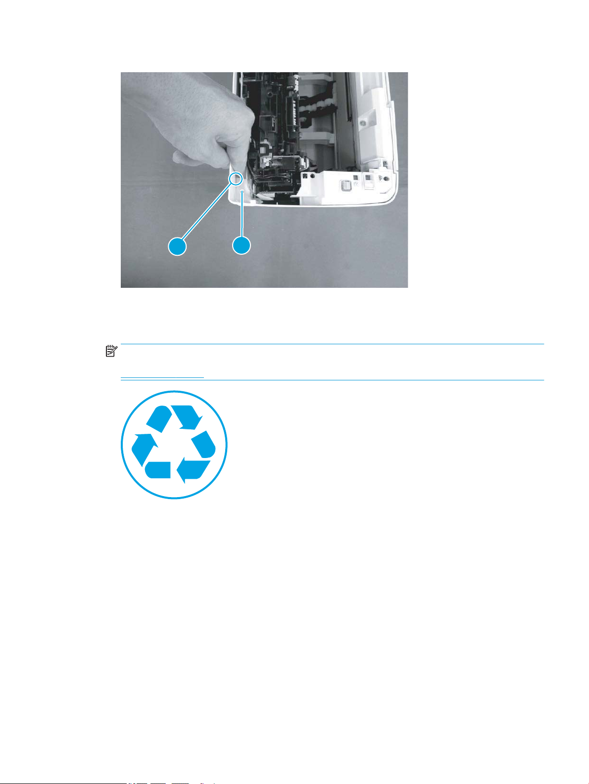
Figure 1-20 Remove the formatter cover (M14-M17)
1
2
Step 3: Unpack the replacement assembly
1. Dispose of the defective part.
NOTE: HP recommends responsible disposal of the defective part.
www.hp.com/recycle
ENWW Removal and replacement procedures 41
Page 64
2. Unpack the replacement part from the packaging.
CAUTION: If the replacement part is a roller or pad, avoid touching the spongy part of it. Skin oils on the
roller or pad can cause paper pickup and/or print-quality problems. HP recommends using disposable
gloves when handling rollers or pads or washing your hands or before touching rollers or pads.
IMPORTANT: Make sure that all of the shipping materials (for example shipping tape) are removed from
the replacement part prior to installation.
42 Chapter 1 Removal and replacement ENWW
Page 65

Remove and replacement: Formatter cover (MFP M28-M31)
●
Introduction
●
Step 1: Remove the formatter cover (MFP M28-M31)
●
Step 2: Unpack the replacement assembly
Introduction
This document provides the procedures to remove and replace the formatter cover (MFP M28-M31).
IMPORTANT: When applicable, special installation instructions are provided for an assembly at the end of the
removal procedure. Always completely read the removal instructions and follow all special installation
instructions.
Before performing service
● Turn the printer power o.
Use the table below to identify the correct part number for your printer. To order the part, go to
www.hp.com/buy/parts
Formatter cover (MFP M28-M31) part number
RC5-4186-000CN Formatter cover (MFP M28-M31)
Required tools
● No special tools are needed to remove or install this assembly.
After performing service
● Turn the printer power on.
Post service test
No post service test is available for this assembly.
Step 1: Remove the formatter cover (MFP M28-M31)
▲ Position the printer front side down.
Remove two screws (callout 1), and then remove the formatter cover (callout 2).
Reinstallation tip: Reverse the removal steps to install the assembly.
ENWW Removal and replacement procedures 43
Page 66
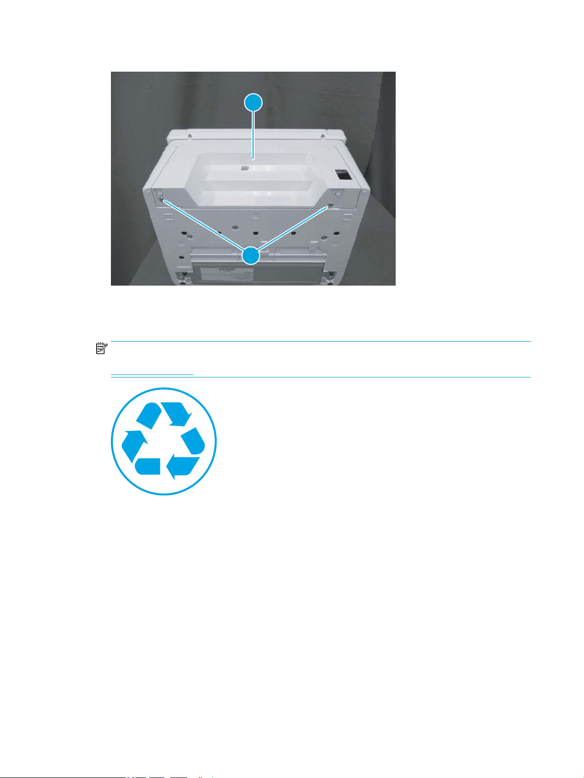
Figure 1-21 Remove the formatter cover (MFP M28-M31)
1
2
Step 2: Unpack the replacement assembly
1. Dispose of the defective part.
NOTE: HP recommends responsible disposal of the defective part.
www.hp.com/recycle
44 Chapter 1 Removal and replacement ENWW
Page 67
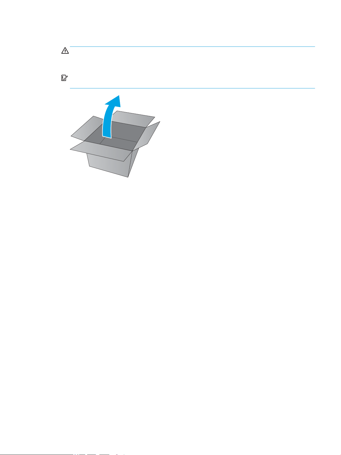
2. Unpack the replacement part from the packaging.
CAUTION: If the replacement part is a roller or pad, avoid touching the spongy part of it. Skin oils on the
roller or pad can cause paper pickup and/or print-quality problems. HP recommends using disposable
gloves when handling rollers or pads or washing your hands or before touching rollers or pads.
IMPORTANT: Make sure that all of the shipping materials (for example shipping tape) are removed from
the replacement part prior to installation.
ENWW Removal and replacement procedures 45
Page 68

Remove and replacement: Cartridge door (MFP M28-M31)
●
Introduction
●
Step 1: Remove the formatter cover (MFP M28-M31)
●
Step 2: Remove the cartridge door (MFP M28-M31)
●
Step 3: Unpack the replacement assembly
Introduction
This document provides the procedures to remove and replace the cartridge door (MFP M28-M31).
IMPORTANT: When applicable, special installation instructions are provided for an assembly at the end of the
removal procedure. Always completely read the removal instructions and follow all special installation
instructions.
Before performing service
● Turn the printer power o.
Use the table below to identify the correct part number for your printer. To order the part, go to
www.hp.com/buy/parts
Cartridge door (MFP M28-M31) part number
RM2-2515-000CN Cartridge door (MFP M28-M31)
Required tools
● #2 Phillips screwdriver with a magnetic tip
● Small at-blade screw driver (optional)
After performing service
● Make sure that the cartridge door is fully closed after replacing it.
● Turn the printer power on.
Post service test
No post service test is available for this assembly.
Step 1: Remove the formatter cover (MFP M28-M31)
▲ Position the printer front side down.
Remove two screws (callout 1), and then remove the formatter cover (callout 2).
Reinstallation tip: Reverse the removal steps to install the assembly.
46 Chapter 1 Removal and replacement ENWW
Page 69
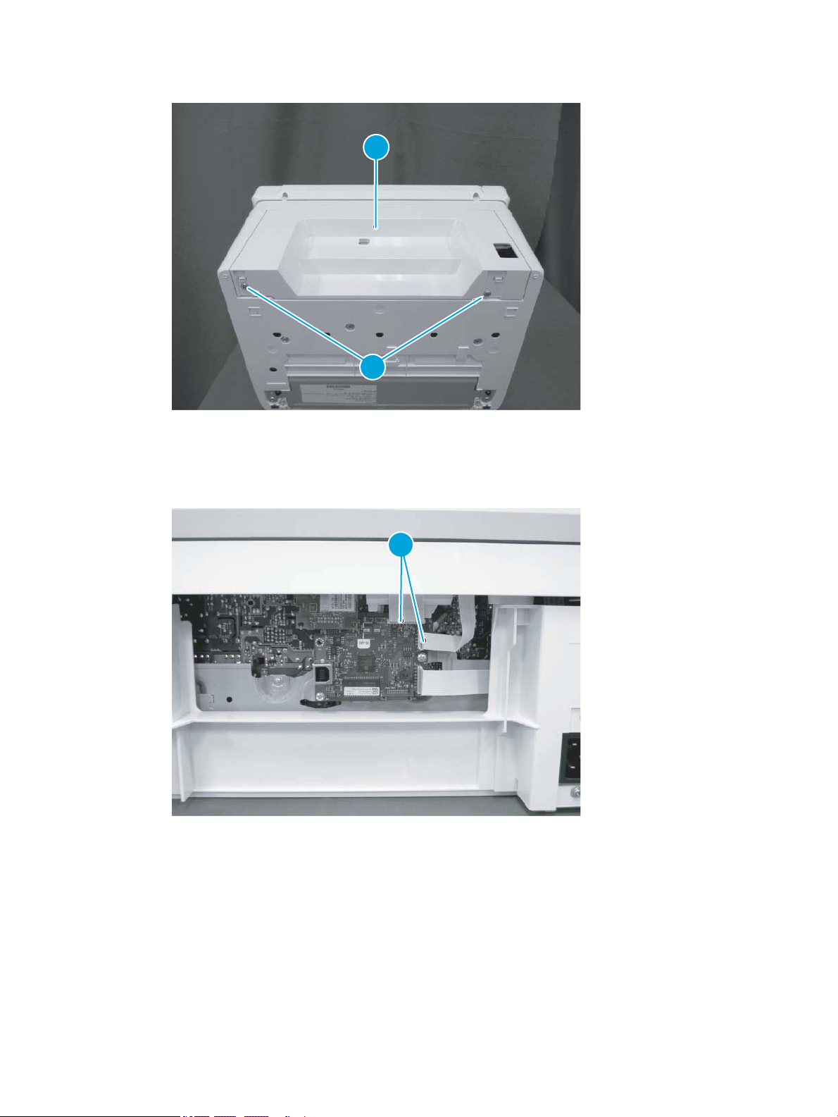
Figure 1-22 Remove the formatter cover (MFP M28-M31)
1
2
1
Step 2: Remove the cartridge door (MFP M28-M31)
1. Disconnect two at exible cables (FFCs) (callout 1).
Figure 1-23 Disconnect two FFCs
ENWW Removal and replacement procedures 47
Page 70
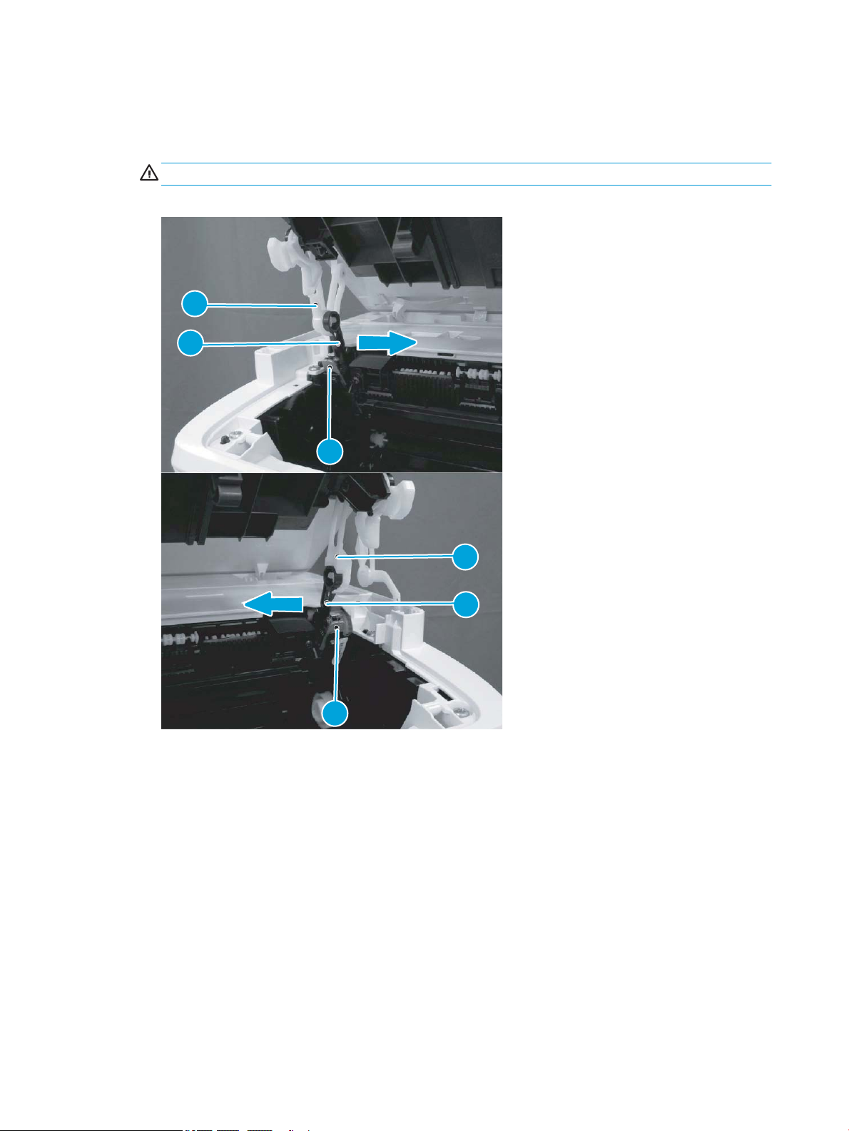
2. Before proceeding, take note of the following disassembly instructions.
1
2
3
3
2
1
When removing the link arm (callout 2) from the pressure release lever (callout 1), the pressure plate
(callout 3) might be deformed if the pressure release lever moves in the direction shown below.
CAUTION: Do not deform the pressure plate.
Figure 1-24 Special disassembly instructions
48 Chapter 1 Removal and replacement ENWW
Page 71
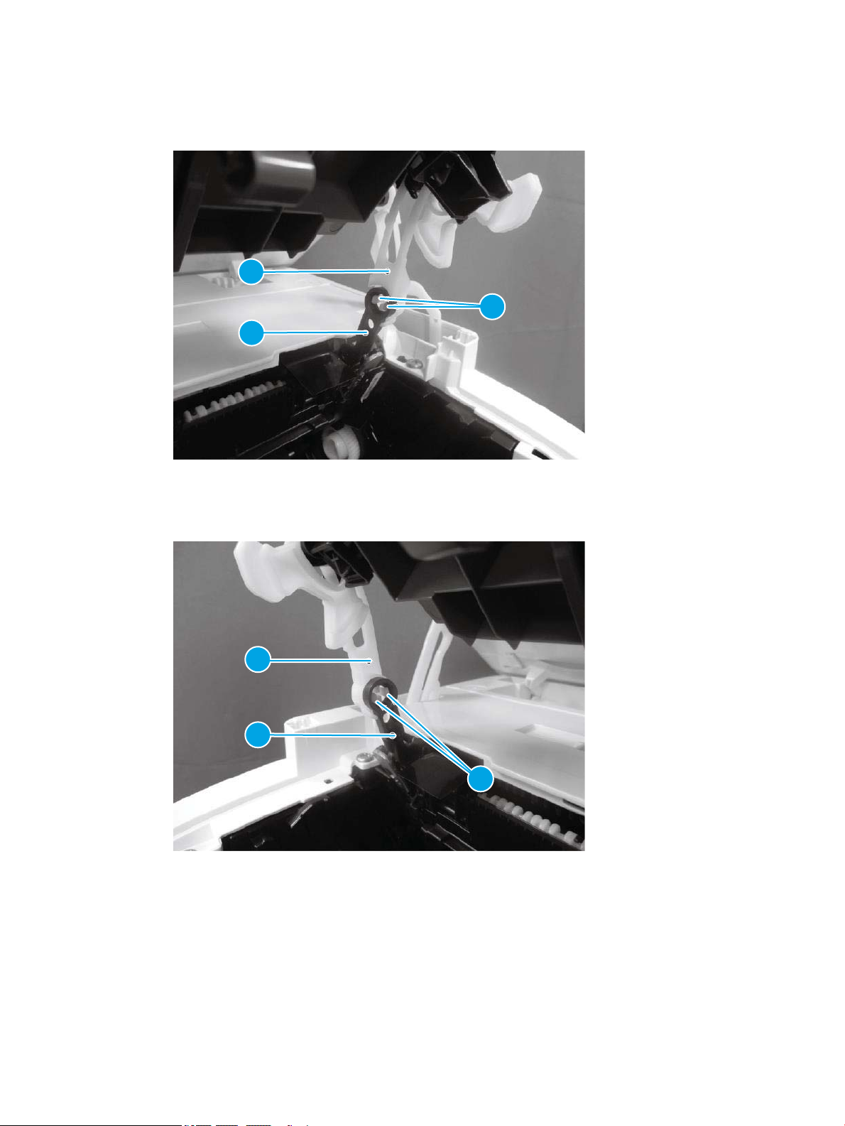
3. Open the image scanner, release two tabs (callout 1), remove one link arm (callout 3) from the pressure
3
2
1
3
2
1
release lever (callout 2).
Figure 1-25 Remove the link arm
4. Release two tabs (callout 1), and then remove one link arm (callout 3) from the pressure release lever
(callout 2).
Figure 1-26 Remove the link arm
ENWW Removal and replacement procedures 49
Page 72
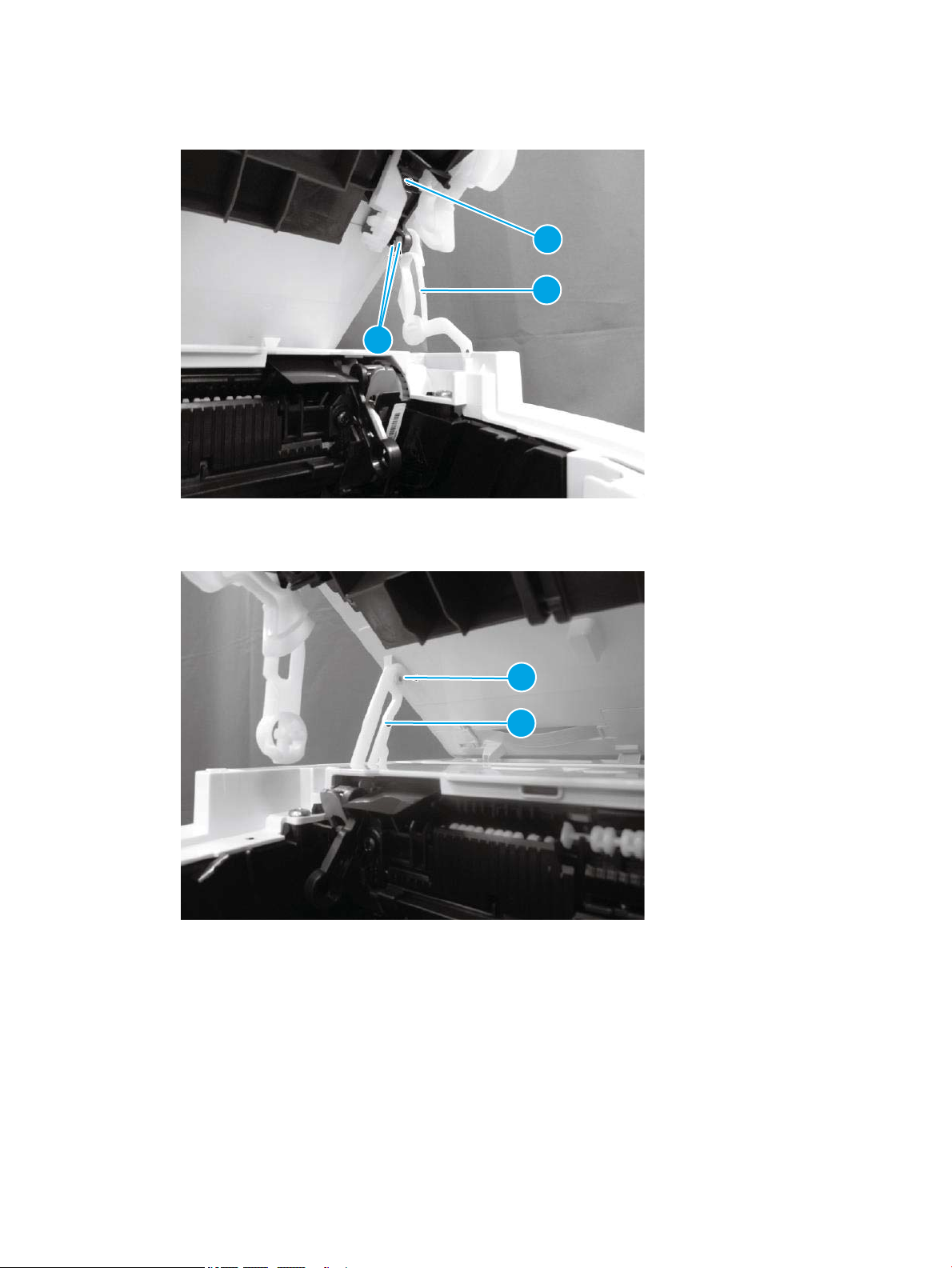
5. Release two tabs (callout 1), and then remove one link arm (callout 3) from the cartridge door (callout 2).
2
3
1
1
2
Figure 1-27 Remove the link arm
6. Remove one link arm (callout 2) from the shaft (callout 1).
Figure 1-28 Remove the link arm
50 Chapter 1 Removal and replacement ENWW
Page 73
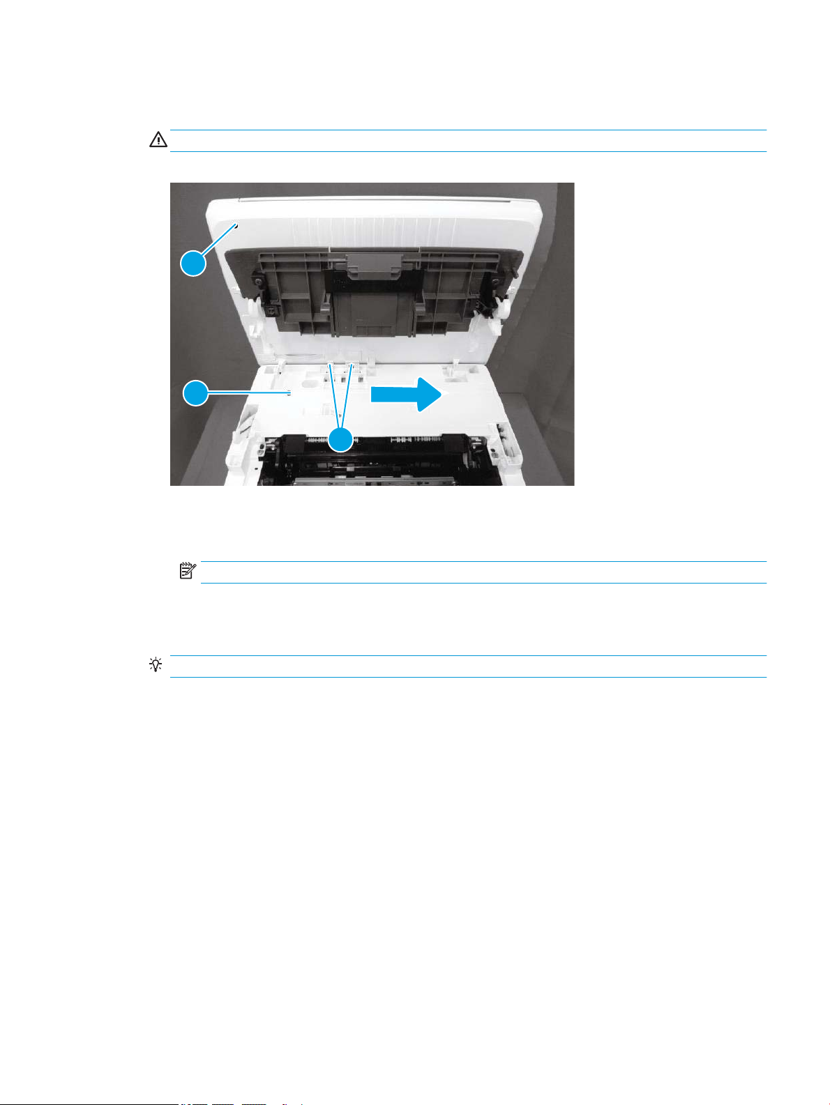
7. Pull two at-exible cables (FFCs) (callout 2) out and away from the top cover (callout 1), and then slide the
1
3
2
image scanner (callout 3) as shown below to remove it.
CAUTION: Do not damage the FFCs.
Figure 1-29 Remove the image scanner
8. Do the following:
● Remove two link two link arms (callout 2) from the cartridge door (callout 1).
NOTE: Install the link arms on the replacement door.
● Remove two screws (callout 3).
● Remove the cartridge door (callout 1) from the image scanner (callout 4).
Reinstallation tip: Reverse the removal steps to install the assembly.
ENWW Removal and replacement procedures 51
Page 74
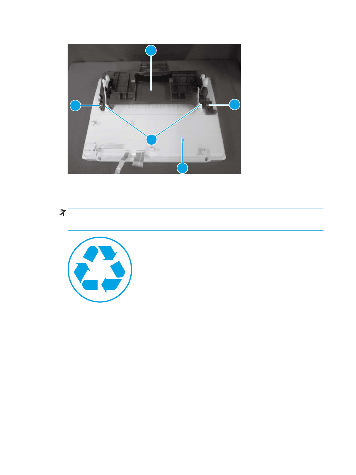
Figure 1-30 Remove the cartridge door
1
3
3
4
4
Step 3: Unpack the replacement assembly
1. Dispose of the defective part.
NOTE: HP recommends responsible disposal of the defective part.
www.hp.com/recycle
52 Chapter 1 Removal and replacement ENWW
Page 75
2. Unpack the replacement part from the packaging.
CAUTION: If the replacement part is a roller or pad, avoid touching the spongy part of it. Skin oils on the
roller or pad can cause paper pickup and/or print-quality problems. HP recommends using disposable
gloves when handling rollers or pads or washing your hands or before touching rollers or pads.
IMPORTANT: Make sure that all of the shipping materials (for example shipping tape) are removed from
the replacement part prior to installation.
ENWW Removal and replacement procedures 53
Page 76

Remove and replacement: Image scanner (MFP M28-M31)
●
Introduction
●
Step 1: Remove the formatter cover (MFP M28-M31)
●
Step 2: Remove the image scanner (MFP M28-M31)
●
Step 3: Unpack the replacement assembly
Introduction
This document provides the procedures to remove and replace the image scanner (MFP M28-M31).
IMPORTANT: When applicable, special installation instructions are provided for an assembly at the end of the
removal procedure. Always completely read the removal instructions and follow all special installation
instructions.
Before performing service
● Turn the printer power o.
Use the table below to identify the correct part number for your printer. To order the part, go to
www.hp.com/buy/parts
Image scanner (MFP M28-M31) part number
RM2-2133-000CN
RM2-2134-000CN
RM2-2135-000CN
Image scanner (base model; MFP M28-M31)
Image scanner (wireless model; MFP M28-M31)
Image scanner (EM model; MFP M28-M31)
Required tools
● #2 Phillips screwdriver with a magnetic tip
● Small at-blade screw driver (optional)
After performing service
● Make sure that the image scanner is fully closed after replacing it.
● Turn the printer power on.
Post service test
Make a copy using the image scanner and verify print quality is acceptable.
Step 1: Remove the formatter cover (MFP M28-M31)
▲ Position the printer front side down.
Remove two screws (callout 1), and then remove the formatter cover (callout 2).
Reinstallation tip: Reverse the removal steps to install the assembly.
54 Chapter 1 Removal and replacement ENWW
Page 77
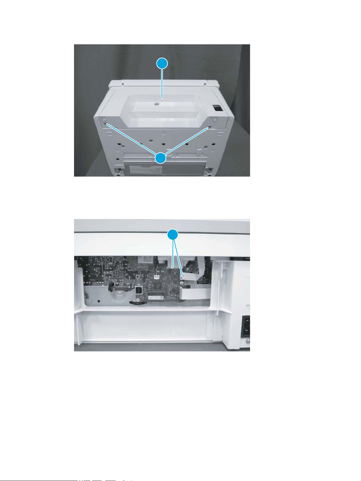
Figure 1-31 Remove the formatter cover (MFP M28-M31)
1
2
1
Step 2: Remove the image scanner (MFP M28-M31)
1. Disconnect two at exible cables (FFCs) (callout 1).
Figure 1-32 Disconnect two FFCs
ENWW Removal and replacement procedures 55
Page 78
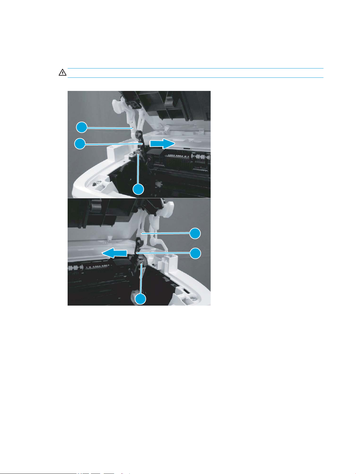
2. Before proceeding, take note of the following disassembly instructions.
1
2
3
3
2
1
When removing the link arm (callout 2) from the pressure release lever (callout 1), the pressure plate
(callout 3) might be deformed if the pressure release lever moves in the direction shown below.
CAUTION: Do not deform the pressure plate.
Figure 1-33 Special disassembly instructions
56 Chapter 1 Removal and replacement ENWW
Page 79
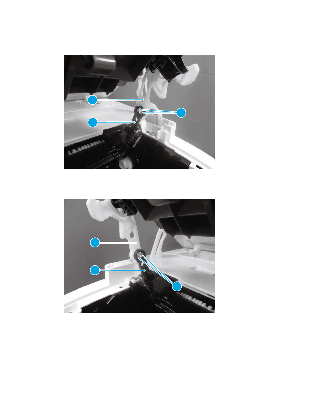
3. Open the image scanner, release two tabs (callout 1), remove one link arm (callout 3) from the pressure
3
2
1
3
2
1
release lever (callout 2).
Figure 1-34 Remove the link arm
4. Release two tabs (callout 1), and then remove one link arm (callout 3) from the pressure release lever
(callout 2).
Figure 1-35 Remove the link arm
ENWW Removal and replacement procedures 57
Page 80
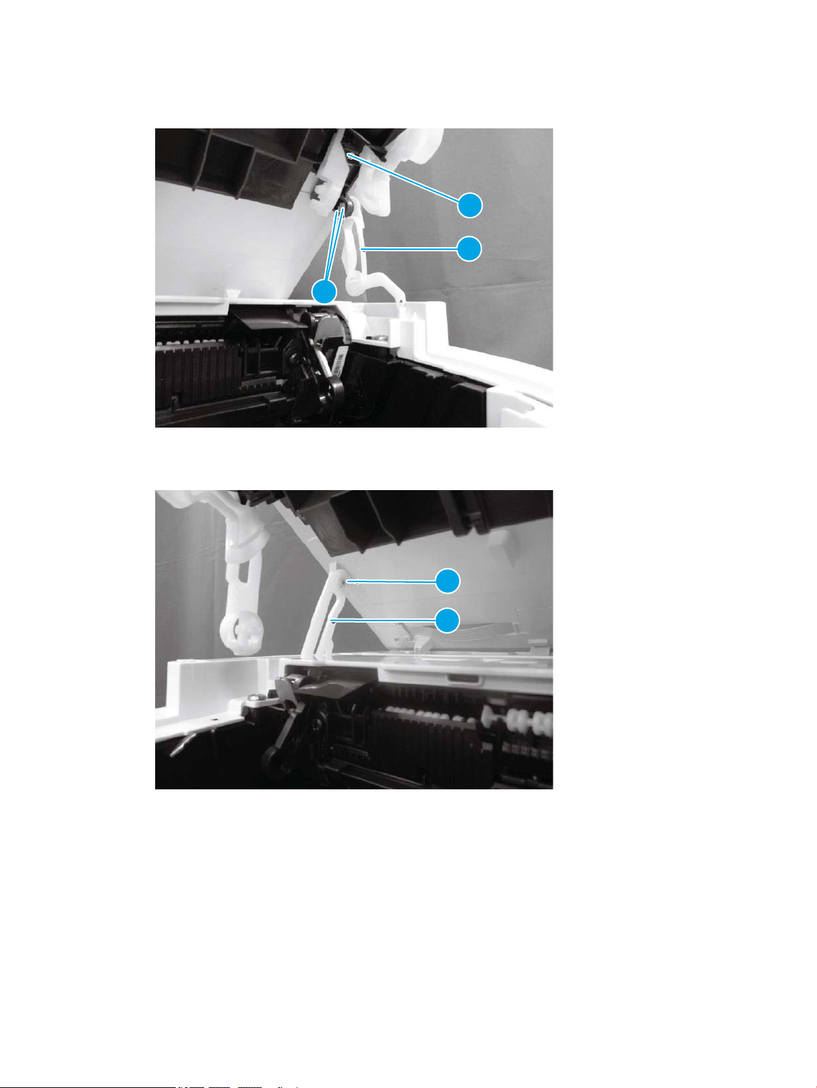
5. Release two tabs (callout 1), and then remove one link arm (callout 3) from the cartridge door (callout 2).
2
3
1
1
2
Figure 1-36 Remove the link arm
6. Remove one link arm (callout 2) from the shaft (callout 1).
Figure 1-37 Remove the link arm
58 Chapter 1 Removal and replacement ENWW
Page 81
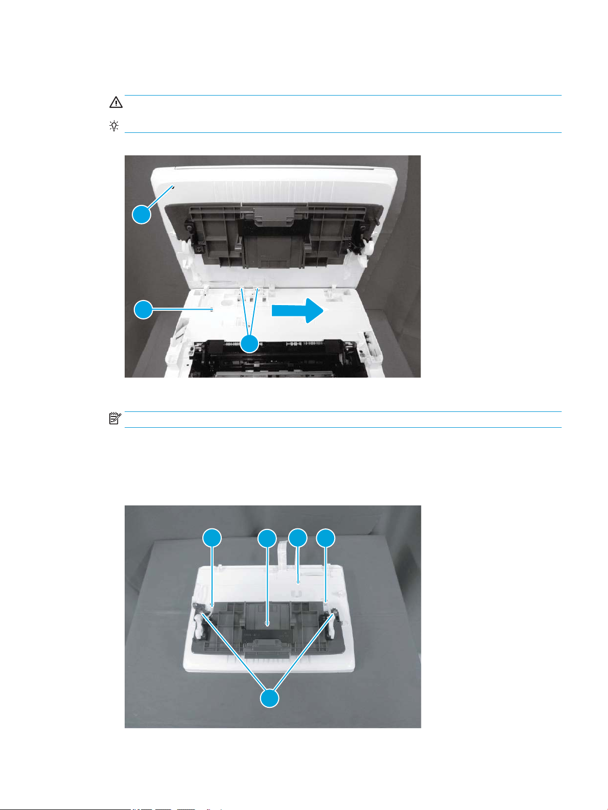
7. Pull two at-exible cables (FFCs) (callout 2) out and away from the top cover (callout 1), and then slide the
1
3
2
1
2
3
4
4
image scanner (callout 3) as shown below to remove it.
CAUTION: Do not damage the FFCs.
Reinstallation tip: Reverse the removal steps to install the assembly.
Figure 1-38 Remove the image scanner
8. For a replacement image scanner, do the following:
NOTE: If the image scanner is removed to access other assemblies, skip this step.
● Remove two screws (callout 1).
● Remove the cartridge door (callout 3) (with the link arms; callout 4) from the image scanner
(callout 2).
Figure 1-39 Remove the cartridge door
ENWW Removal and replacement procedures 59
Page 82
Step 3: Unpack the replacement assembly
1. Dispose of the defective part.
NOTE: HP recommends responsible disposal of the defective part.
www.hp.com/recycle
2. Unpack the replacement part from the packaging.
CAUTION: If the replacement part is a roller or pad, avoid touching the spongy part of it. Skin oils on the
roller or pad can cause paper pickup and/or print-quality problems. HP recommends using disposable
gloves when handling rollers or pads or washing your hands or before touching rollers or pads.
IMPORTANT: Make sure that all of the shipping materials (for example shipping tape) are removed from
the replacement part prior to installation.
60 Chapter 1 Removal and replacement ENWW
Page 83

Remove and replacement: Lower cover (M14-M17)
●
Introduction
●
Step 1: Remove the cartridge door (M14-M17)
●
Step 2: Remove the formatter cover (M14-M17)
●
Step 3: Remove the lower cover (M14-M17)
●
Step 4: Unpack the replacement assembly
Introduction
This document provides the procedures to remove and replace the lower cover (M14-M17).
IMPORTANT: When applicable, special installation instructions are provided for an assembly at the end of the
removal procedure. Always completely read the removal instructions and follow all special installation
instructions.
Before performing service
● Turn the printer power o.
Use the table below to identify the correct part number for your printer. To order the part, go to
www.hp.com/buy/parts
Lower cover (M14-M17) part number
RM2-2105-000CN
RM2-2104-000CN
Required tools
● #2 Phillips screwdriver with a magnetic tip
After performing service
● Turn the printer power on.
Post service test
No post service test is available for this assembly.
Step 1: Remove the cartridge door (M14-M17)
1. Open the cartridge door, and then remove two screws (callout 1).
Lower cover (base model; M14-M17)
Lower cover (wireless model; M14-M17)
ENWW Removal and replacement procedures 61
Page 84
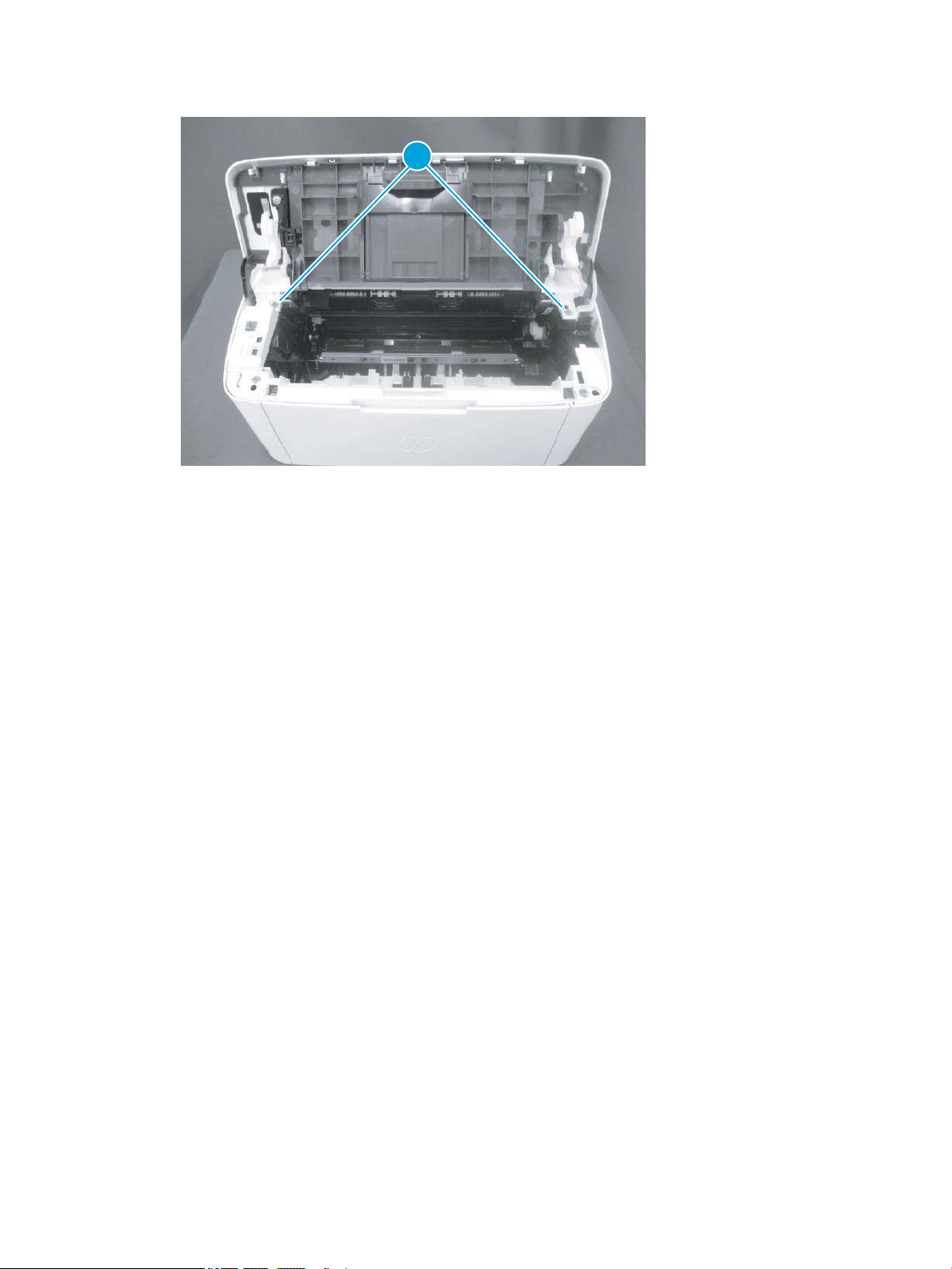
Figure 1-40 Remove two screw
1
62 Chapter 1 Removal and replacement ENWW
Page 85
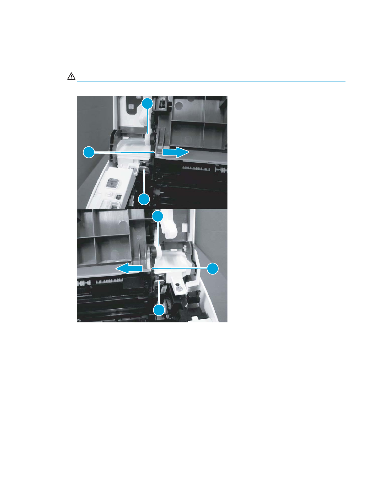
2. Before proceeding, take note of the following disassembly instructions.
1
2
3
3
2
1
When removing the link arm (callout 2) from the pressure release lever (callout 1), the pressure plate
(callout 3) might be deformed if the pressure release lever moves in the direction shown below.
CAUTION: Do not deform the pressure plate.
Figure 1-41 Special disassembly instructions
ENWW Removal and replacement procedures 63
Page 86

3. Release two tabs (callout 1), and then remove one link arm (callout 3) from the pressure release lever
3
2
1
3
2
1
(callout 2).
Figure 1-42 Remove the link arm
4. Release two tabs (callout 1), and then remove one link arm (callout 3) from the pressure release lever
(callout 2).
Figure 1-43 Remove the link arm
64 Chapter 1 Removal and replacement ENWW
Page 87
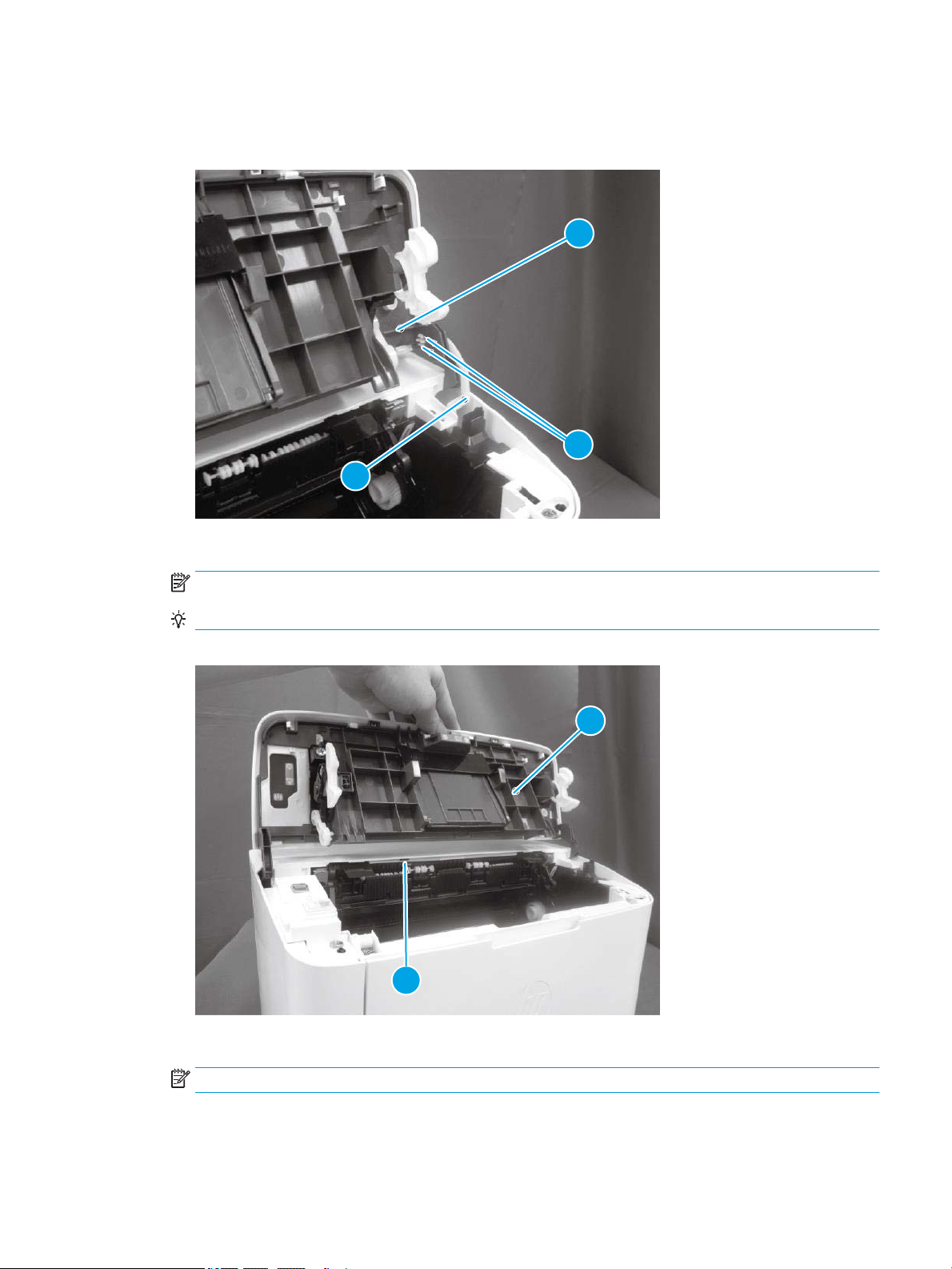
5. Release two tabs (callout 1), and then remove one link arm (callout 3) from the cartridge door assembly
2
3
1
1
2
(callout 2).
Figure 1-44 Remove the link arm
6. Release one tab (callout 1), support the cartridge door (callout 2), and then remove it.
NOTE: If the cartridge door is removed to access other assembly, stop at this step.
Reinstallation tip: Reverse the removal steps to install the door.
Figure 1-45 Remove the cartridge door
7. Optional step: If a replacement cartridge door is being installed, do the following:
NOTE: Install the link arms on the replacement door.
a. Release two tabs (callout 1), and then remove the one link arm (callout 3) from the door assembly
(callout 2).
ENWW Removal and replacement procedures 65
Page 88
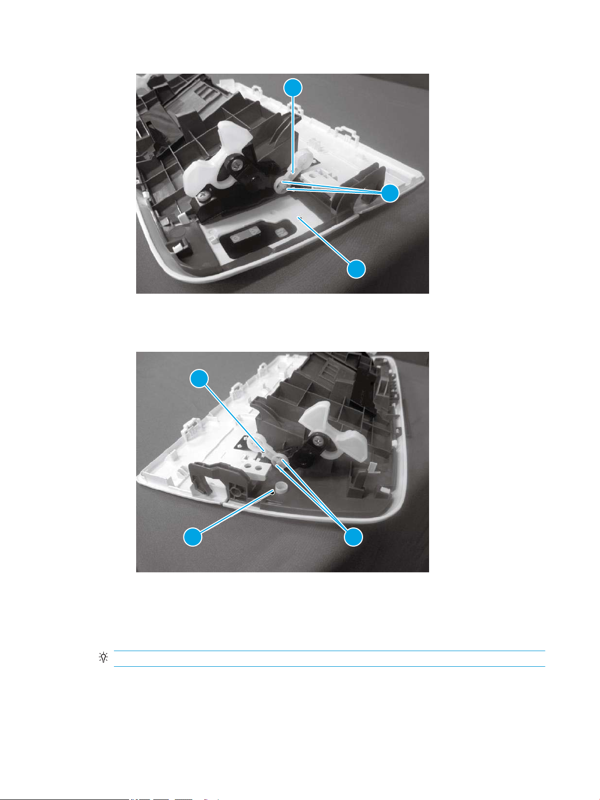
Figure 1-46 Install the link arms on the replacement door
3
2
1
3
2 1
b. Release two tabs (callout 1), and then remove the one link arm (callout 3) from the door assembly
(callout 2).
Figure 1-47 Install the link arms on the replacement door
Step 2: Remove the formatter cover (M14-M17)
▲ Position the printer front side down.
Release one tab (callout 1), and then remove the formatter cover (callout 2).
Reinstallation tip: Reverse the removal steps to install the assembly.
66 Chapter 1 Removal and replacement ENWW
Page 89
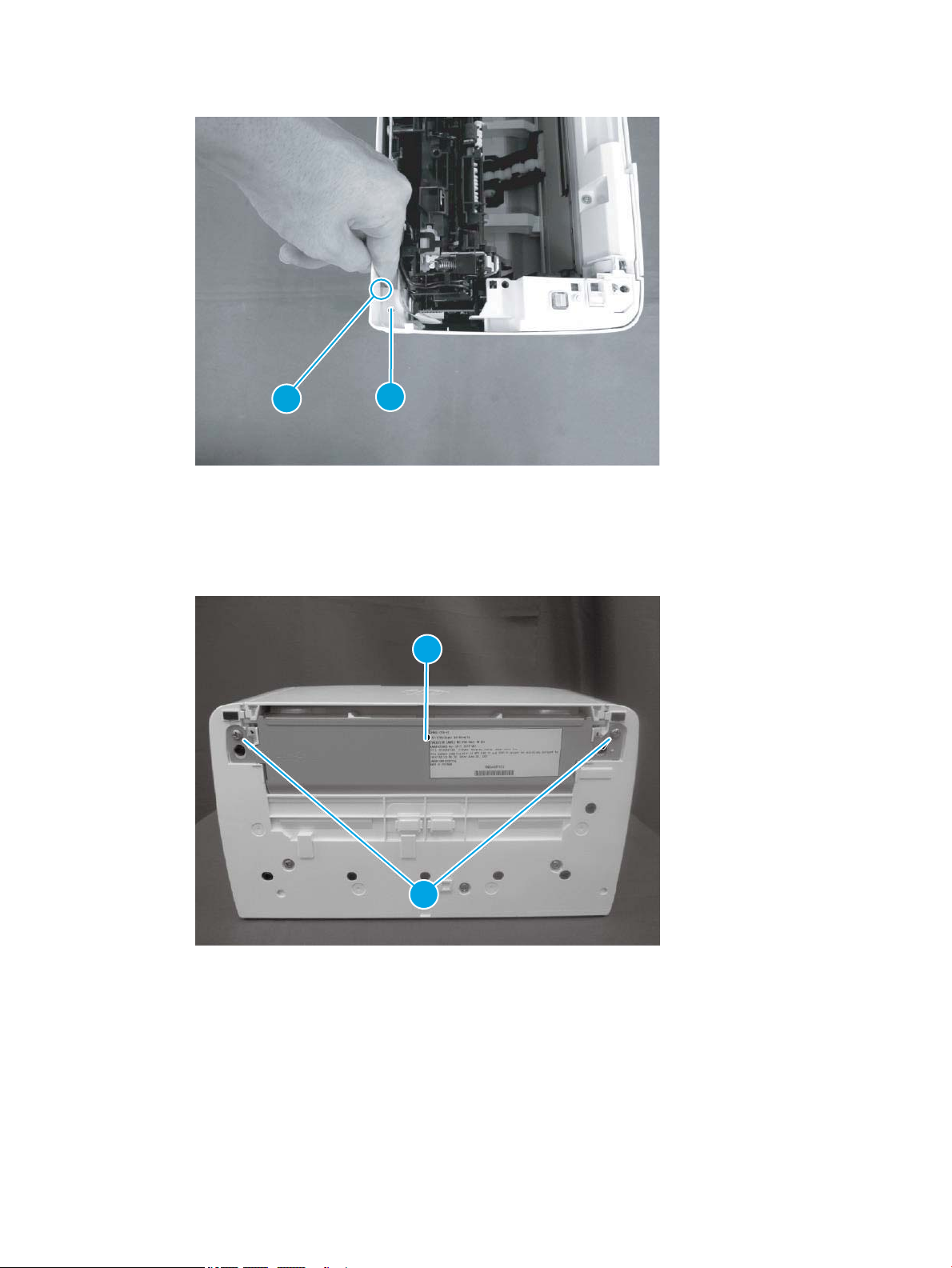
Figure 1-48 Remove the formatter cover (M14-M17)
1
2
2
1
Step 3: Remove the lower cover (M14-M17)
1. Position the printer rear side down, remove three screws (callout 1), and then remove the lower plate
(callout 2).
Figure 1-49 Remove the lower plate
ENWW Removal and replacement procedures 67
Page 90
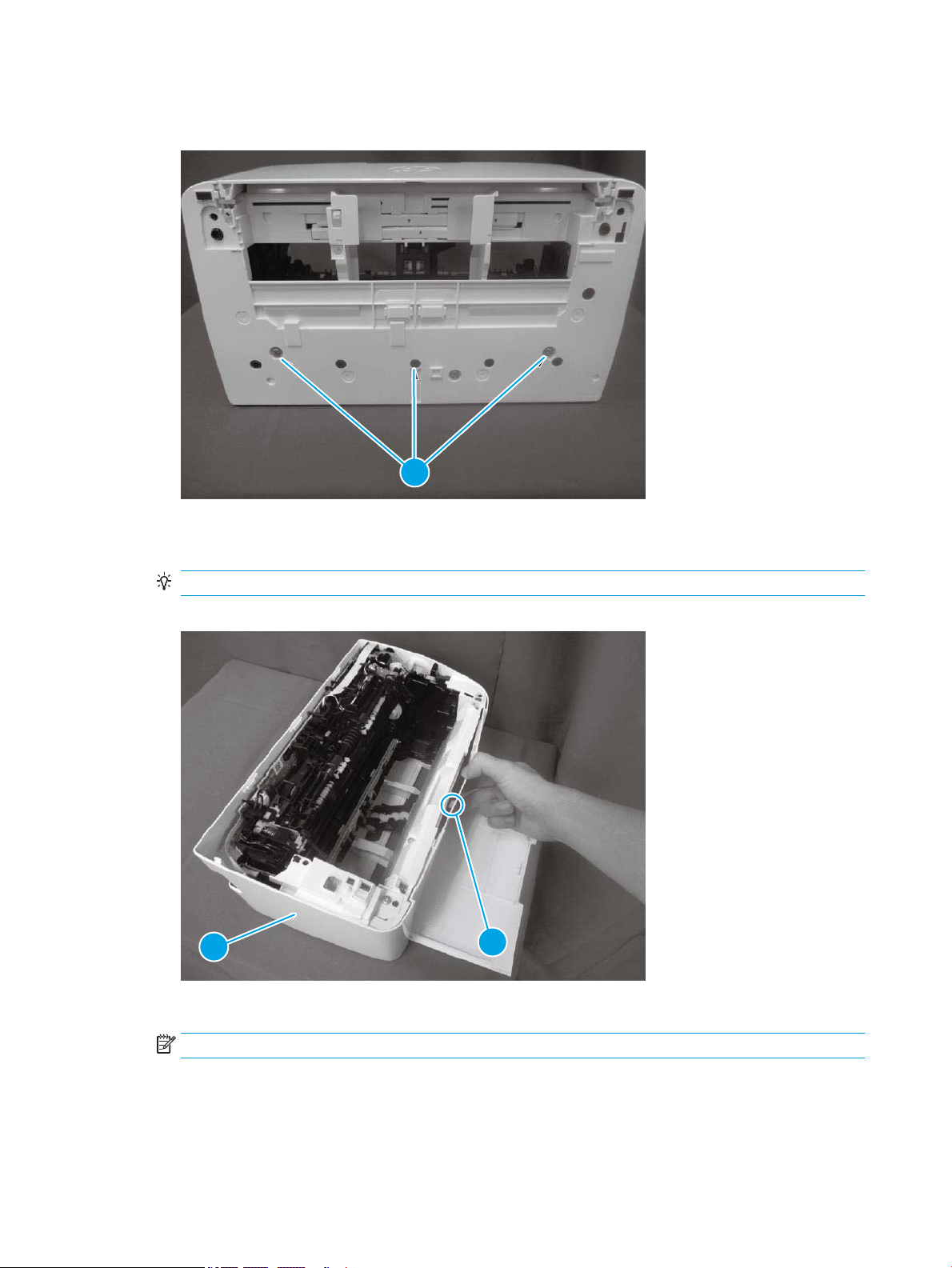
2. Remove three screws (callout 1)
1
1
2
Figure 1-50 Remove the three screws
3. With the printer in the upright position, release one tab (callout 1), and then remove the lower cover
(callout 2).
Reinstallation tip: Reverse the removal steps to install the assembly.
Figure 1-51 Remove the lower cover
4. Reverse the removal steps to install the assembly. Also use the following special installation instructions.
NOTE: Continue to reverse the removal steps to nish installing the assembly.
Special installation instructions: Lower cover
▲ Make sure to t two ribs (callout 1) on the printer into the grooves (callout 2) in the lower cover.
68 Chapter 1 Removal and replacement ENWW
Page 91
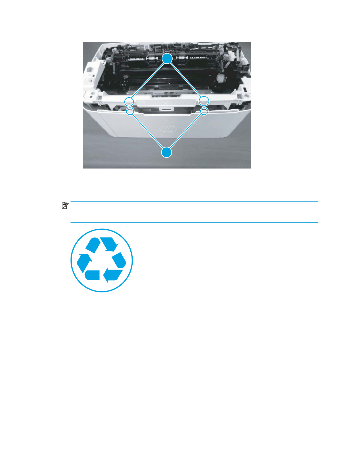
Figure 1-52 Fit two ribs on the printer into the grooves (lower cover install)
1
2
Step 4: Unpack the replacement assembly
1. Dispose of the defective part.
NOTE: HP recommends responsible disposal of the defective part.
www.hp.com/recycle
ENWW Removal and replacement procedures 69
Page 92
2. Unpack the replacement part from the packaging.
CAUTION: If the replacement part is a roller or pad, avoid touching the spongy part of it. Skin oils on the
roller or pad can cause paper pickup and/or print-quality problems. HP recommends using disposable
gloves when handling rollers or pads or washing your hands or before touching rollers or pads.
IMPORTANT: Make sure that all of the shipping materials (for example shipping tape) are removed from
the replacement part prior to installation.
70 Chapter 1 Removal and replacement ENWW
Page 93

Remove and replacement: Lower cover (MFP M28-M31)
●
Introduction
●
Step 1: Remove the formatter cover (MFP M28-M31)
●
Step 2: Remove the image scanner (MFP M28-M31)
●
Step 3: Remove the top cover (MFP M28-M31)
●
Step 4: Remove the lower cover (MFP M28-M31)
●
Step 5: Unpack the replacement assembly
Introduction
This document provides the procedures to remove and replace the lower cover (MFP M28-M31).
IMPORTANT: When applicable, special installation instructions are provided for an assembly at the end of the
removal procedure. Always completely read the removal instructions and follow all special installation
instructions.
Before performing service
● Turn the printer power o.
Use the table below to identify the correct part number for your printer. To order the part, go to
www.hp.com/buy/parts
Lower cover (MFP M28-M31) part number
RM2-2103-000CN Lower cover (MFP M28-M31)
Required tools
● #2 Phillips screwdriver with a magnetic tip
After performing service
● Turn the printer power on.
Post service test
No post service test is available for this assembly.
Step 1: Remove the formatter cover (MFP M28-M31)
▲ Position the printer front side down.
Remove two screws (callout 1), and then remove the formatter cover (callout 2).
Reinstallation tip: Reverse the removal steps to install the assembly.
ENWW Removal and replacement procedures 71
Page 94
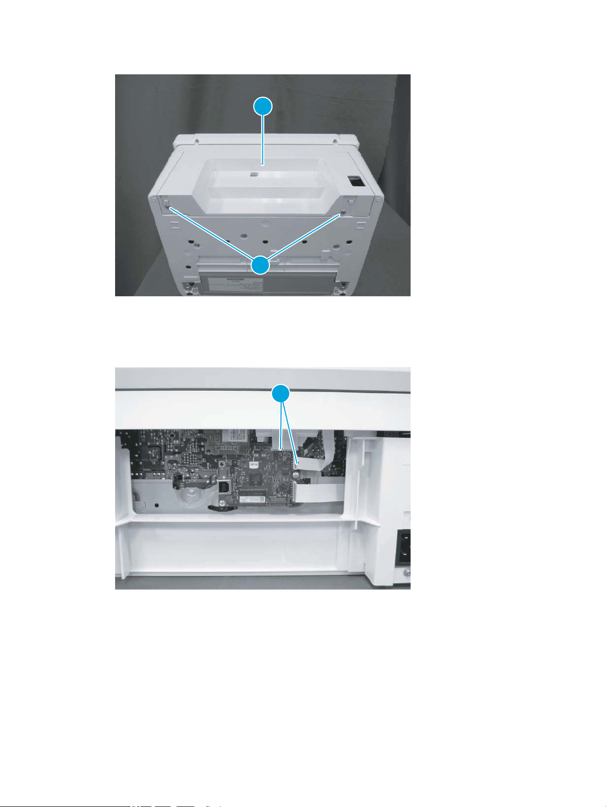
Figure 1-53 Remove the formatter cover (MFP M28-M31)
1
2
1
Step 2: Remove the image scanner (MFP M28-M31)
1. Disconnect two at exible cables (FFCs) (callout 1).
Figure 1-54 Disconnect two FFCs
72 Chapter 1 Removal and replacement ENWW
Page 95
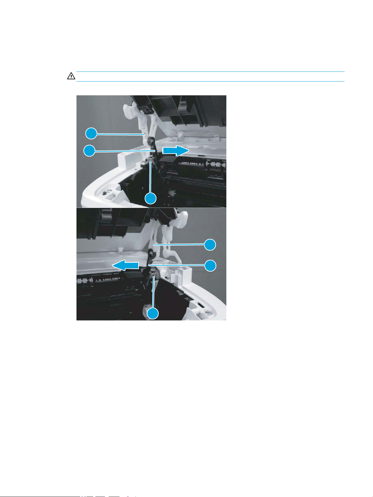
2. Before proceeding, take note of the following disassembly instructions.
1
2
3
3
2
1
When removing the link arm (callout 2) from the pressure release lever (callout 1), the pressure plate
(callout 3) might be deformed if the pressure release lever moves in the direction shown below.
CAUTION: Do not deform the pressure plate.
Figure 1-55 Special disassembly instructions
ENWW Removal and replacement procedures 73
Page 96
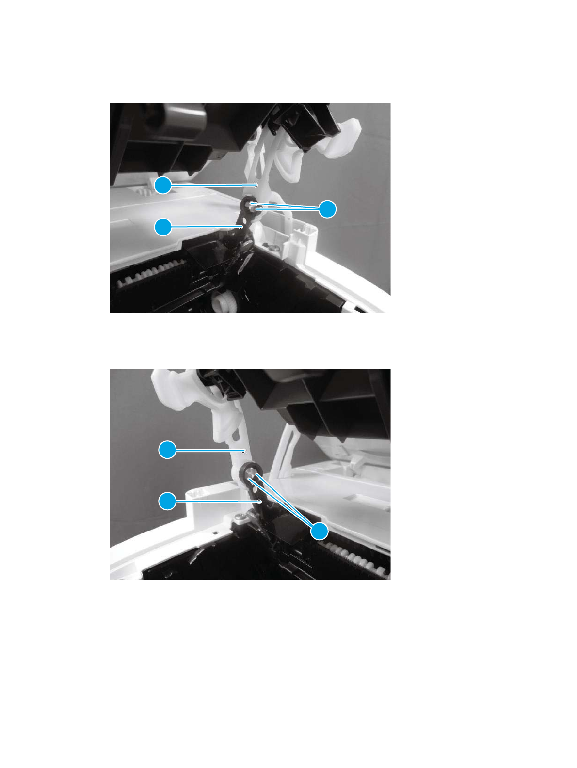
3. Open the image scanner, release two tabs (callout 1), remove one link arm (callout 3) from the pressure
3
2
1
3
2
1
release lever (callout 2).
Figure 1-56 Remove the link arm
4. Release two tabs (callout 1), and then remove one link arm (callout 3) from the pressure release lever
(callout 2).
Figure 1-57 Remove the link arm
74 Chapter 1 Removal and replacement ENWW
Page 97
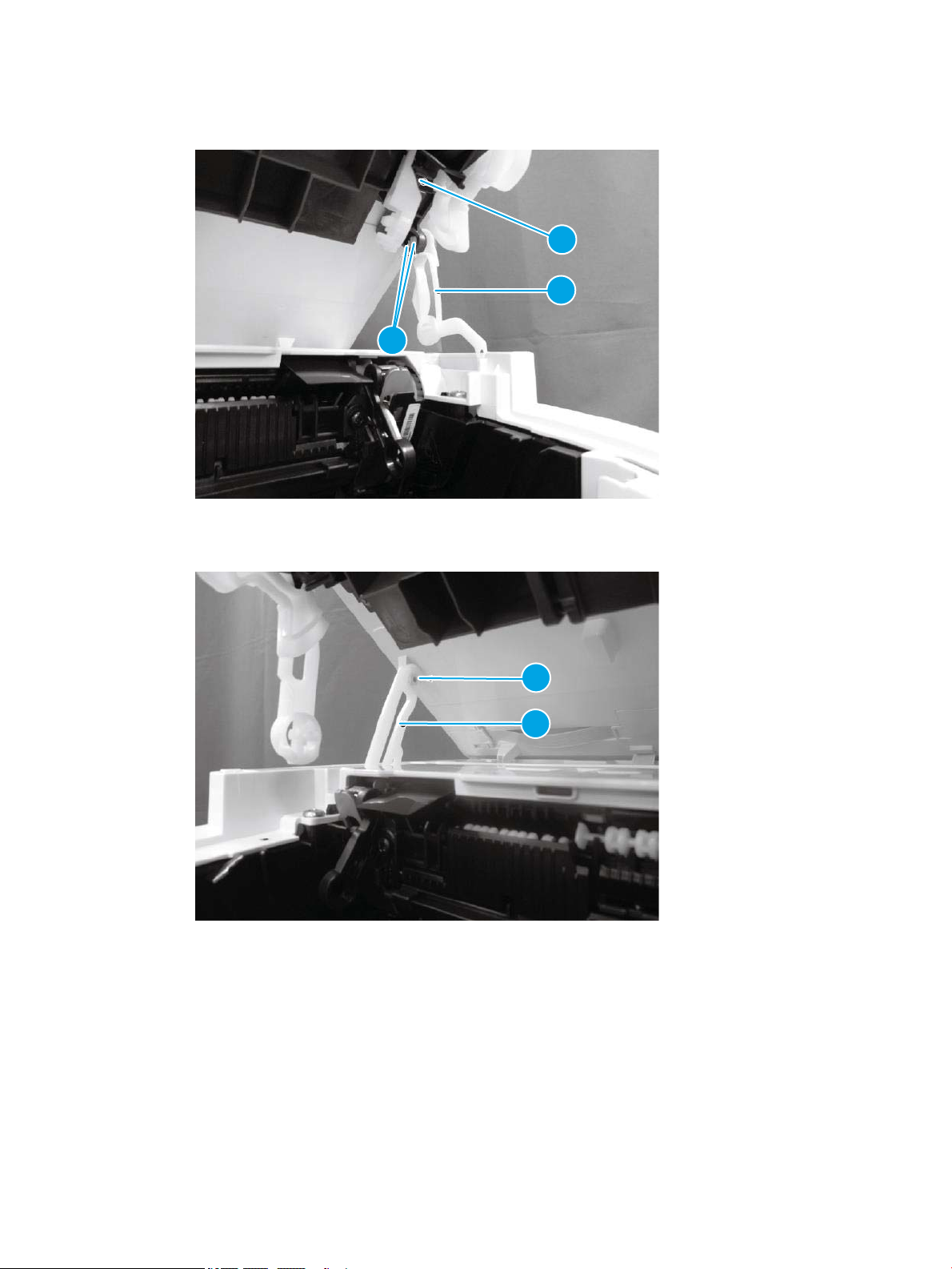
5. Release two tabs (callout 1), and then remove one link arm (callout 3) from the cartridge door (callout 2).
2
3
1
1
2
Figure 1-58 Remove the link arm
6. Remove one link arm (callout 2) from the shaft (callout 1).
Figure 1-59 Remove the link arm
ENWW Removal and replacement procedures 75
Page 98
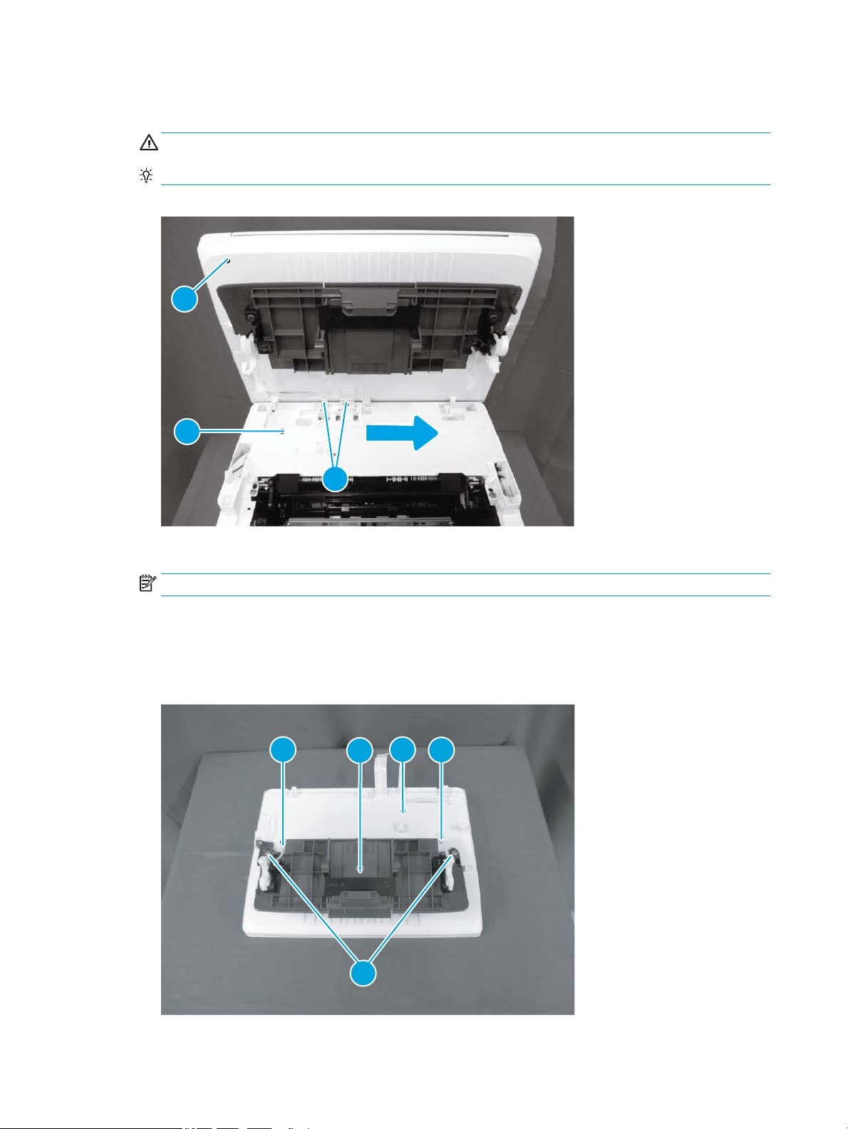
7. Pull two at-exible cables (FFCs) (callout 2) out and away from the top cover (callout 1), and then slide the
1
3
2
1
2
3
4
4
image scanner (callout 3) as shown below to remove it.
CAUTION: Do not damage the FFCs.
Reinstallation tip: Reverse the removal steps to install the assembly.
Figure 1-60 Remove the image scanner
8. For a replacement image scanner, do the following:
NOTE: If the image scanner is removed to access other assemblies, skip this step.
● Remove two screws (callout 1).
● Remove the cartridge door (callout 3) (with the link arms; callout 4) from the image scanner
(callout 2).
Figure 1-61 Remove the cartridge door
76 Chapter 1 Removal and replacement ENWW
Page 99
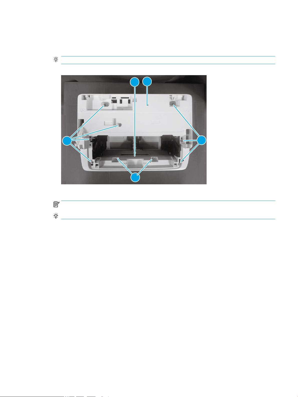
Step 3: Remove the top cover (MFP M28-M31)
1
2
2
3
4
1. Remove two screws (M3; callout 1), remove seven screws (M4; callout 2), release one tab (callout 3), and
then remove the top cover (callout 4).
Reinstallation tip: Reverse the removal steps to install the assembly.
Figure 1-62 Remove the top cover
2. Reverse the removal steps to install the assembly. Also use the following special installation instructions.
NOTE: Continue to reverse the removal steps to nish installing the assembly.
TIP: If the top cover is removed to access other assemblies, skip this step.
Special installation instructions: Top cover
▲ Remove the pad (callout 2) from the top cover (callout 1), and then install it on the replacement top
cover.
ENWW Removal and replacement procedures 77
Page 100
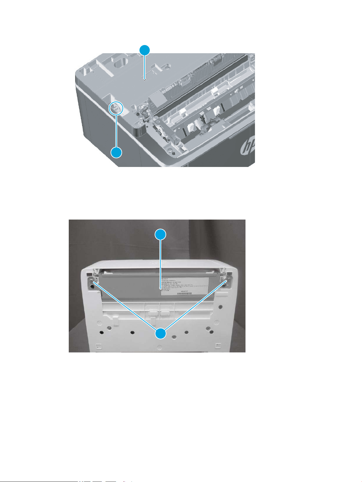
Figure 1-63 Install the pad
2
1
2
1
Step 4: Remove the lower cover (MFP M28-M31)
1. Position the printer rear side down, remove two screws (callout 1), and then remove the lower plate
(callout 2)
Figure 1-64 Remove the lower plate
78 Chapter 1 Removal and replacement ENWW
 Loading...