

Page 1
LASERJET PROFESSIONAL P1560 and P1600
SERIES PRINTER
Service Manual
www.hp.com/support/ljp1560series
www.hp.com/support/ljp1600series
Page 2

HP LaserJet Professional P1560 and
P1600 Series Printer
Service Manual
Page 3

Copyright and License
Trademark Credits
© 2010 Copyright Hewlett-Packard
Development Company, L.P.
Reproduction, adaptation, or translation
without prior written permission is prohibited,
except as allowed under the copyright laws.
The information contained herein is subject
to change without notice.
The only warranties for HP products and
services are set forth in the express warranty
statements accompanying such products
and services. Nothing herein should be
construed as constituting an additional
warranty. HP shall not be liable for technical
or editorial errors or omissions contained
herein.
Part number: CE663-90939
Edition 1, 4/2010
Microsoft®, Windows®, Windows® XP, and
Windows Vista® are U.S. registered
trademarks of Microsoft Corporation.
Page 4

Conventions used in this guide
TIP: Tips provide helpful hints or shortcuts.
NOTE: Notes provide important information to explain a concept or to complete a task.
CAUTION: Cautions indicate procedures that you should follow to avoid losing data or damaging the
product.
WARNING! Warnings alert you to specific procedures that you should follow to avoid personal injury,
catastrophic loss of data, or extensive damage to the product.
ENWW iii
Page 5

Table of contents
1 Theory of operation ........................................................................................................................................ 1
Basic operation ..................................................................................................................................... 2
Major product systems ......................................................................................................... 2
Product block diagram ......................................................................................................... 2
Sequence of operation ......................................................................................................... 3
Normal sequence of operation ............................................................................ 3
Formatter-control system ..................................................................................................................... 4
Sleep mode .......................................................................................................................... 4
Input/output .......................................................................................................................... 4
CPU ..................................................................................................................................... 4
Memory ................................................................................................................................ 4
Firmware ............................................................................................................. 5
Memory use ........................................................................................................ 5
PJL overview ....................................................................................................................... 5
LEDM overview .................................................................................................................... 5
ACL overview ....................................................................................................................... 5
Control panel ....................................................................................................................... 6
Engine-control system .......................................................................................................................... 7
Motors, fans, clutches, solenoids, switches, and sensors ................................................... 8
DC controller operations .................................................................................................... 13
Fuser-control circuit ........................................................................................................... 15
Fuser failure detection ....................................................................................... 16
Fuser temperature control ................................................................................. 17
Fuser protective function ................................................................................... 18
Pressure roller cleaning .................................................................................... 18
Low-voltage power supply ................................................................................................. 19
Overcurrent/overvoltage protection ................................................................... 20
High-voltage power supply ................................................................................................ 21
Laser/scanner system ........................................................................................................ 22
Laser failure detection ....................................................................................... 23
Image-formation system ..................................................................................................................... 24
Electrophotographic process ............................................................................................. 24
Image formation process ................................................................................................... 26
Latent-image formation stage ........................................................................... 27
ENWW v
Page 6

Primary charging .............................................................................. 27
Laser beam exposure ....................................................................... 27
Developing stage .............................................................................................. 28
Print cartridge ................................................................................... 28
Transfer stage ................................................................................................... 29
Fusing stage ..................................................................................... 29
Cleaning stage .................................................................................. 30
Pickup, feed, and delivery system ...................................................................................................... 31
Photo sensors and switches .............................................................................................. 32
Main-input tray or priority input slot .................................................................................................... 34
Jam detection .................................................................................................................... 34
2 Removal and replacement ........................................................................................................................... 35
Introduction ......................................................................................................................................... 36
Removal and replacement strategy ................................................................................................... 36
Electrostatic discharge ....................................................................................................................... 37
Required tools ................................................................................................................................... 37
Before performing service .................................................................................................................. 37
After performing service ..................................................................................................................... 38
Post-service test ................................................................................................................................. 38
Print-quality test ................................................................................................................. 38
Parts removal order ............................................................................................................................ 39
Pickup roller ........................................................................................................................................ 40
Separation pad ................................................................................................................................... 41
Transfer roller ..................................................................................................................................... 42
Covers ................................................................................................................................................ 43
Main-input tray ................................................................................................................... 43
Output bin tray extension ................................................................................................... 44
Left cover, simplex product ................................................................................................ 45
Remove the left cover, simplex product ............................................................ 45
Left cover, duplex product ................................................................................................. 47
Remove the left cover, duplex product .............................................................. 47
Right cover, simplex product ............................................................................................. 50
Remove the right cover, simplex product .......................................................... 50
Right cover, duplex product ............................................................................................... 52
Remove the right cover, duplex product ........................................................... 52
Duplex door, duplex product .............................................................................................. 55
Duplex frame, duplex product ............................................................................................ 56
Remove the duplex frame ................................................................................. 56
Cartridge door .................................................................................................................... 57
Control panel ..................................................................................................................... 59
Front cover ......................................................................................................................... 61
Remove the front cover ..................................................................................... 61
vi ENWW
Page 7

Rear cover, simplex product .............................................................................................. 63
Remove the rear cover, simplex product .......................................................... 63
Face-down cover ............................................................................................................... 65
Remove the face-down cover ........................................................................... 65
Main assemblies ................................................................................................................................. 67
Formatter PCA ................................................................................................................... 67
Laser/scanner assembly .................................................................................................... 68
Remove the laser/scanner assembly ................................................................ 68
Reinstall the laser/scanner assembly ................................................................ 71
Pickup assembly ................................................................................................................ 72
Remove the pickup assembly ........................................................................... 72
Reinstall the pickup assembly ........................................................................... 78
Fuser .................................................................................................................................. 80
Remove the fuser .............................................................................................. 80
Reinstall the fuser ............................................................................................. 86
Main motor ......................................................................................................................... 87
Remove the main motor .................................................................................... 87
Reinstall the main-motor drive belt .................................................................... 92
Pickup solenoid .................................................................................................................. 93
Remove the pickup solenoid ............................................................................. 93
Engine controller PCA ....................................................................................................... 97
Remove the engine controller PCA ................................................................... 97
Reinstall the engine controller PCA ................................................................ 102
Duplex-reverse solenoid, duplex product ........................................................................ 104
Remove the duplex-reverse solenoid .............................................................. 104
Main fan, duplex product ................................................................................................. 107
Remove the main fan ...................................................................................... 107
Reinstall the main fan ...................................................................................... 109
Duplex-connector PCA, duplex product ........................................................................... 110
Remove the duplex-connector PCA ................................................................ 110
3 Solve problems ........................................................................................................................................... 113
Solve problems checklist .................................................................................................................. 114
Troubleshooting process .................................................................................................................. 116
Determine the problem source ....................................................................................... 116
Power subsystem ............................................................................................................ 117
Power-on checks ............................................................................................. 117
Tools for troubleshooting .................................................................................................................. 118
Individual component diagnostics .................................................................................... 118
Engine diagnostics .......................................................................................... 118
Engine-test button .......................................................................... 118
Components tests ........................................................................................... 119
Drum rotation functional check ...................................................... 119
ENWW vii
Page 8

Half self-test functional check ......................................................... 119
Diagrams ......................................................................................................................... 120
Plug/jack locations .......................................................................................... 120
Location of connectors .................................................................................... 121
Locations of major components ...................................................................... 122
General timing charts ...................................................................................... 125
General circuit diagram ................................................................................... 126
Internal print-quality test pages ........................................................................................ 127
Cleaning page ................................................................................................. 127
Configuration page .......................................................................................... 127
Print-quality troubleshooting tools .................................................................................... 128
Repetitive defect ruler ..................................................................................... 128
Interpret control-panel light patterns ................................................................................ 128
Clear jams ........................................................................................................................................ 133
Common causes of jams ................................................................................................. 133
Jam locations ................................................................................................................... 133
Clear jams from the input trays ........................................................................................ 134
Clear jams from the duplexer ........................................................................................... 136
Clear jams from the output areas .................................................................................... 138
Clear jams from inside the product .................................................................................. 139
Solve repeated jams ........................................................................................................ 141
Change jam recovery ...................................................................................................... 142
Solve paper-handling problems ........................................................................................................ 143
Solve image-quality problems .......................................................................................................... 144
Image defect table ........................................................................................................... 144
Light print or faded .......................................................................................... 144
Toner specks ................................................................................................... 144
Dropouts .......................................................................................................... 145
Vertical lines .................................................................................................... 145
Gray background ............................................................................................. 145
Toner smear .................................................................................................... 146
Loose toner ..................................................................................................... 146
Vertical repetitive defects ................................................................................ 146
Misformed characters ...................................................................................... 146
Page skew ....................................................................................................... 147
Curl or wave .................................................................................................... 147
Wrinkles or creases ......................................................................................... 147
Toner scatter outline ....................................................................................... 148
Moisture .......................................................................................................... 148
Change print density ........................................................................................................ 149
Clean the product ............................................................................................................................. 150
Clean the pickup roller ..................................................................................................... 150
Clean the paper path ....................................................................................................... 151
Clean the print-cartridge area .......................................................................................... 153
viii ENWW
Page 9

Clean the exterior ............................................................................................................ 154
Solve performance problems ........................................................................................................... 155
Solve connectivity problems ............................................................................................................. 156
Solve direct-connect problems ........................................................................................ 156
Solve network problems .................................................................................................. 156
Service mode functions .................................................................................................................... 158
Product resets .................................................................................................................. 158
Product updates ............................................................................................................................... 158
Firmware updates ............................................................................................................ 158
4 Parts and diagrams ..................................................................................................................................... 159
Order parts by authorized service providers .................................................................................... 160
Order replacement parts .................................................................................................. 160
Related documentation and software .............................................................................. 160
Supplies part numbers ..................................................................................................... 160
Customer self repair parts ............................................................................................... 161
Service parts .................................................................................................................... 161
Whole-unit replacement part numbers ............................................................................. 161
How to use the parts lists and diagrams .......................................................................................... 162
Assembly locations ........................................................................................................................... 163
Base product (no optional trays or accessories) .............................................................. 163
Covers .............................................................................................................................................. 164
Simplex model ................................................................................................................. 164
Duplex model ................................................................................................................... 16 6
Internal assemblies .......................................................................................................................... 168
Internal assemblies (1 of 3) ............................................................................................. 168
Internal assemblies (2 of 3) ............................................................................................. 170
Internal assemblies (3 of 3) ............................................................................................. 172
PCAs ................................................................................................................................................ 174
Alphabetical parts list ....................................................................................................................... 176
Numerical parts list ........................................................................................................................... 179
Appendix A Service and support ................................................................................................................. 183
Hewlett-Packard limited warranty statement .................................................................................... 184
HP's Premium Protection Warranty: LaserJet print cartridge limited warranty statement ................ 185
End User License Agreement .......................................................................................................... 186
Customer self-repair warranty service .............................................................................................. 188
Customer support ............................................................................................................................. 188
Repack the product .......................................................................................................................... 189
Service information form .................................................................................................................. 190
Appendix B Specifications ............................................................................................................................ 191
Physical specifications ..................................................................................................................... 192
ENWW ix
Page 10

Power consumption .......................................................................................................................... 192
Acoustic specifications ..................................................................................................................... 192
Environmental specifications ............................................................................................................ 193
Appendix C Regulatory information ............................................................................................................ 195
FCC regulations ............................................................................................................................... 196
Declaration of conformity .................................................................................................................. 197
Certificate of Volatility ....................................................................................................................... 198
Safety statements ............................................................................................................................. 200
Laser safety ..................................................................................................................... 200
Canadian DOC regulations .............................................................................................. 200
VCCI statement (Japan) .................................................................................................. 200
Power cord instructions ................................................................................................... 200
Power cord statement (Japan) ......................................................................................... 200
EMC statement (Korea) ................................................................................................... 200
Laser statement for Finland ............................................................................................. 201
GS statement (Germany) ................................................................................................. 201
Substances Table (China) ............................................................................................... 202
Restriction on Hazardous Substances statement (Turkey) ............................................. 202
Index ................................................................................................................................................................. 203
x ENWW
Page 11

List of tables
Table 1-1 Sequence of operation ....................................................................................................................... 3
Table 1-2 Motors ................................................................................................................................................ 8
Table 1-3 Fans ................................................................................................................................................... 9
Table 1-4 Solenoids and clutches .................................................................................................................... 10
Table 1-5 Switches ........................................................................................................................................... 11
Table 1-6 Sensors ............................................................................................................................................ 11
Table 1-7 DC controller controlled components ............................................................................................... 13
Table 1-8 Photo sensors, motor, and solenoid ................................................................................................ 32
Table 3-1 Basic problem solving .................................................................................................................... 114
Table 3-2 Status-light legend ......................................................................................................................... 128
Table 3-3 Control-panel lights ........................................................................................................................ 129
Table 4-1 Order parts, accessories, and supplies .......................................................................................... 160
Table 4-2 Related documentation and software ............................................................................................ 160
Table 4-3 Supplies part numbers ................................................................................................................... 160
Table 4-4 Customer replaceable units (CRU) kit part numbers ..................................................................... 161
Table 4-5 Whole-unit replacement part numbers ........................................................................................... 161
Table 4-6 Base product .................................................................................................................................. 163
Table 4-7 Simplex model ................................................................................................................................ 165
Table 4-8 Duplex model ................................................................................................................................. 167
Table 4-9 Internal assemblies (1 of 3) ............................................................................................................ 169
Table 4-10 Internal assemblies (2 of 3) .......................................................................................................... 171
Table 4-11 Internal assemblies (3 of 3) .......................................................................................................... 173
Table 4-12 PCAs ............................................................................................................................................ 175
Table 4-13 Alphabetical parts list ................................................................................................................... 176
Table 4-14 Numerical parts list ....................................................................................................................... 179
Table B-1 Physical specifications
Table B-2 HP LaserJet Professional P1560 and P1600 Printer series (average in watts)
Table B-3 HP LaserJet Professional P1560 and P1600 Printer series
Table B-4 Environmental specifications ......................................................................................................... 193
1
.................................................................................................................. 192
123
......................... 192
12
........................................................ 192
ENWW xi
Page 12

List of figures
Figure 1-1 Product block diagram ...................................................................................................................... 2
Figure 1-2 Engine-control system ...................................................................................................................... 7
Figure 1-3 Motors ............................................................................................................................................... 8
Figure 1-4 Fans .................................................................................................................................................. 9
Figure 1-5 Solenoids and clutches ................................................................................................................... 10
Figure 1-6 Switches .......................................................................................................................................... 11
Figure 1-7 Sensors ........................................................................................................................................... 11
Figure 1-8 DC controller block diagram ............................................................................................................ 13
Figure 1-9 Fuser control circuit ......................................................................................................................... 15
Figure 1-10 Fuser-heater control circuit ........................................................................................................... 17
Figure 1-11 Low-voltage power supply (LVPS) ................................................................................................ 19
Figure 1-12 High-voltage power supply ............................................................................................................ 21
Figure 1-13 Laser/scanner system ................................................................................................................... 22
Figure 1-14 Electrophotographic process block diagram (1 of 2) .................................................................... 24
Figure 1-15 Electrophotographic process block diagram (2 of 2) .................................................................... 25
Figure 1-16 Image formation process .............................................................................................................. 26
Figure 1-17 Primary charging ........................................................................................................................... 27
Figure 1-18 Laser beam exposure ................................................................................................................... 27
Figure 1-19 Print cartridge ................................................................................................................................ 28
Figure 1-20 Transfer ......................................................................................................................................... 29
Figure 1-21 Separation ..................................................................................................................................... 29
Figure 1-22 Fusing ........................................................................................................................................... 30
Figure 1-23 Drum cleaning ............................................................................................................................... 30
Figure 1-24 Pickup, feed, and delivery system block diagram ......................................................................... 31
Figure 1-25 Photo sensors, motor, and solenoid ............................................................................................. 32
Figure 2-1 Phillips and pozidrive screwdriver comparison ............................................................................... 37
Figure 2-2 Parts removal order ........................................................................................................................ 39
Figure 2-3 Remove the pickup roller (1 of 2) .................................................................................................... 40
Figure 2-4 Remove the pickup roller (2 of 2) .................................................................................................... 40
Figure 2-5 Remove the separation pad assembly ........................................................................................... 41
Figure 2-6 Remove the transfer roller .............................................................................................................. 42
Figure 2-7 Remove the tray .............................................................................................................................. 43
Figure 2-8 Remove the output bin tray extension ............................................................................................ 44
Figure 2-9 Remove the left cover, simplex product (1 of 4) ............................................................................. 45
ENWW xiii
Page 13

Figure 2-10 Remove the left cover, simplex product (2 of 4) ........................................................................... 45
Figure 2-11 Remove the left cover, simplex product (3 of 4) ........................................................................... 46
Figure 2-12 Remove the left cover, simplex product (4 of 4) ........................................................................... 46
Figure 2-13 Remove the left cover, duplex product (1 of 5) ............................................................................. 47
Figure 2-14 Remove the left cover, duplex product (2 of 5) ............................................................................. 47
Figure 2-15 Remove the left cover, duplex product (3 of 5) ............................................................................. 48
Figure 2-16 Remove the left cover, duplex product (4 of 5) ............................................................................. 48
Figure 2-17 Remove the left cover, duplex product (5 of 5) ............................................................................. 49
Figure 2-18 Remove the right cover, simplex product (1 of 4) ......................................................................... 50
Figure 2-19 Remove the right cover, simplex product (2 of 4) ......................................................................... 50
Figure 2-20 Remove the right cover, simplex product (4 of 4) ......................................................................... 51
Figure 2-21 Remove the right cover, duplex product (1 of 5) ........................................................................... 52
Figure 2-22 Remove the right cover, duplex product (2 of 5) ........................................................................... 52
Figure 2-23 Remove the right cover, duplex product (3 of 5) ........................................................................... 53
Figure 2-24 Remove the right cover, duplex product (4 of 5) ........................................................................... 53
Figure 2-25 Remove the right cover, duplex product (5 of 5) ........................................................................... 54
Figure 2-26 Remove the duplex door, duplex product ..................................................................................... 55
Figure 2-27 Remove the duplex frame (1 of 2) ................................................................................................ 56
Figure 2-28 Remove the duplex frame (2 of 2) ................................................................................................ 56
Figure 2-29 Remove the cartridge door (1 of 3) ............................................................................................... 57
Figure 2-30 Remove the cartridge door (2 of 3) ............................................................................................... 57
Figure 2-31 Remove the cartridge door (3 of 3) ............................................................................................... 58
Figure 2-32 Remove the control panel (1 of 3) ................................................................................................ 59
Figure 2-33 Remove the control panel (2 of 3) ................................................................................................ 59
Figure 2-34 Remove the control panel (3 of 3) ................................................................................................ 60
Figure 2-35 Remove the front cover (1 of 3) .................................................................................................... 61
Figure 2-36 Remove the front cover (2 of 3) .................................................................................................... 62
Figure 2-37 Remove the front cover (3 of 3) .................................................................................................... 62
Figure 2-38 Remove the rear cover, simplex product (1 of 3) .......................................................................... 63
Figure 2-39 Remove the rear cover, simplex product (2 of 3) .......................................................................... 64
Figure 2-40 Remove the rear cover, simplex product (2 of 3) .......................................................................... 64
Figure 2-41 Remove the face-down cover (1 of 2) ........................................................................................... 65
Figure 2-42 Remove the face-down cover (2 of 2) ........................................................................................... 66
Figure 2-43 Remove the formatter PCA (1 of 2) .............................................................................................. 67
Figure 2-44 Remove the formatter PCA (2 of 2) .............................................................................................. 67
Figure 2-45 Remove the laser/scanner assembly (1 of 5) ............................................................................... 68
Figure 2-46 Remove the laser/scanner assembly (2 of 5) ............................................................................... 69
Figure 2-47 Remove the laser/scanner assembly (3 of 5) ............................................................................... 69
Figure 2-48 Remove the laser/scanner assembly (4 of 5) ............................................................................... 70
Figure 2-49 Remove the laser/scanner assembly (5 of 5) ............................................................................... 70
Figure 2-50 Reinstall the laser/scanner assembly ........................................................................................... 71
Figure 2-51 Remove the pickup assembly (1 of 10) ........................................................................................ 72
Figure 2-52 Remove the pickup assembly (2 of 10) ........................................................................................ 73
Figure 2-53 Remove the pickup assembly (3 of 10) ........................................................................................ 73
xiv ENWW
Page 14

Figure 2-54 Remove the pickup assembly (4 of 10) ........................................................................................ 74
Figure 2-55 Remove the pickup assembly (5 of 10) ........................................................................................ 74
Figure 2-56 Remove the pickup assembly (6 of 10) ........................................................................................ 75
Figure 2-57 Remove the pickup assembly (7 of 10) ........................................................................................ 75
Figure 2-58 Remove the pickup assembly (8 of 10) ........................................................................................ 76
Figure 2-59 Remove the pickup assembly (9 of 10) ........................................................................................ 76
Figure 2-60 Remove the pickup assembly (10 of 10) ...................................................................................... 77
Figure 2-61 Reinstall the pickup assembly (1 of 4; correct ground spring position) ......................................... 78
Figure 2-62 Reinstall the pickup assembly (2 of 4; incorrect ground spring position) ...................................... 78
Figure 2-63 Reinstall the pickup assembly (3 of 4; lift plate in raised position) ................................................ 79
Figure 2-64 Reinstall the pickup assembly (4 of 4; lift plate in lowered position) ............................................. 79
Figure 2-65 Remove the fuser (1 of 10) ........................................................................................................... 80
Figure 2-66 Remove the fuser (2 of 10) ........................................................................................................... 81
Figure 2-67 Remove the fuser (3 of 10) ........................................................................................................... 81
Figure 2-68 Remove the fuser (4 of 10) ........................................................................................................... 82
Figure 2-69 Remove the fuser (5 of 10) ........................................................................................................... 82
Figure 2-70 Remove the fuser (6 of 10) ........................................................................................................... 83
Figure 2-71 Remove the fuser (7 of 10) ........................................................................................................... 83
Figure 2-72 Remove the fuser (8 of 10) ........................................................................................................... 84
Figure 2-73 Remove the fuser (9 of 10) ........................................................................................................... 84
Figure 2-74 Remove the fuser (10 of 10) ......................................................................................................... 85
Figure 2-75 Reinstall the fuser; correct wire harness installation ..................................................................... 86
Figure 2-76 Reinstall the fuser; incorrect wire harness installation .................................................................. 86
Figure 2-77 Remove the main motor (1 of 9) ................................................................................................... 87
Figure 2-78 Remove the main motor (2 of 9) ................................................................................................... 88
Figure 2-79 Remove the main motor (3 of 9) ................................................................................................... 88
Figure 2-80 Remove the main motor (4 of 9) ................................................................................................... 89
Figure 2-81 Remove the main motor (5 of 9) ................................................................................................... 89
Figure 2-82 Remove the main motor (6 of 9) ................................................................................................... 90
Figure 2-83 Remove the main motor (7 of 9) ................................................................................................... 90
Figure 2-84 Remove the main motor (8 of 9) ................................................................................................... 91
Figure 2-85 Remove the main motor (9 of 9) ................................................................................................... 91
Figure 2-86 Main-motor drive belt: correctly installed ...................................................................................... 92
Figure 2-87 Main-motor drive belt: incorrectly installed .................................................................................... 92
Figure 2-88 Remove the pickup solenoid (1 of 7) ............................................................................................ 93
Figure 2-89 Remove the pickup solenoid (2 of 7) ............................................................................................ 94
Figure 2-90 Remove the pickup solenoid (3 of 7) ............................................................................................ 94
Figure 2-91 Remove the pickup solenoid (4 of 7) ............................................................................................ 95
Figure 2-92 Remove the solenoid (5 of 7) ........................................................................................................ 95
Figure 2-93 Remove the pickup solenoid (6 of 7) ............................................................................................ 96
Figure 2-94 Remove the pickup solenoid (7 of 7) ............................................................................................ 96
Figure 2-95 Remove the engine controller PCA (1 of 9) .................................................................................. 97
Figure 2-96 Remove the engine controller PCA (2 of 9) .................................................................................. 98
Figure 2-97 Remove the engine controller PCA (3 of 9) .................................................................................. 98
ENWW xv
Page 15

Figure 2-98 Remove the engine controller PCA (4 of 9) .................................................................................. 99
Figure 2-99 Remove the engine controller PCA (5 of 9) .................................................................................. 99
Figure 2-100 Remove the engine controller PCA (6 of 9) .............................................................................. 100
Figure 2-101 Remove the engine controller PCA (7 of 9) .............................................................................. 100
Figure 2-102 Remove the engine controller PCA (8 of 9) .............................................................................. 101
Figure 2-103 Remove the engine controller PCA (10 of 9) ............................................................................ 101
Figure 2-104 Reinstall the engine controller PCA (1 of 4) .............................................................................. 102
Figure 2-105 Reinstall the engine controller PCA (2 of 4) .............................................................................. 102
Figure 2-106 Reinstall the engine controller PCA (3 of 4) .............................................................................. 103
Figure 2-107 Reinstall the engine controller PCA (4 of 4) .............................................................................. 103
Figure 2-108 Remove the duplex-reverse solenoid (1 of 5) ........................................................................... 104
Figure 2-109 Remove the duplex-reverse solenoid (2 of 5) ........................................................................... 105
Figure 2-110 Remove the duplex-reverse solenoid (3 of 5) ........................................................................... 105
Figure 2-111 Remove the duplex-reverse solenoid (4 of 5) ........................................................................... 106
Figure 2-112 Remove the duplex-reverse solenoid (5 of 5) ........................................................................... 106
Figure 2-113 Remove the main fan (1 of 4) ................................................................................................... 107
Figure 2-114 Remove the main fan (2 of 4) ................................................................................................... 108
Figure 2-115 Remove the main fan (3 of 4) ................................................................................................... 108
Figure 2-116 Remove the main fan (4 of 4) ................................................................................................... 109
Figure 2-117 Reinstall the main fan ............................................................................................................... 109
Figure 2-118 Remove the duplex-connector PCA (1 of 5) ............................................................................. 110
Figure 2-119 Remove the duplex-connector PCA (2 of 5) ............................................................................. 111
Figure 2-120 Remove the duplex-connector PCA (3 of 5) ............................................................................. 111
Figure 2-121 Remove the duplex-connector PCA (4 of 5) ............................................................................. 112
Figure 2-122 Remove the duplex-connector PCA (5 of 5) ............................................................................. 112
Figure 3-1 Sample engine test page .............................................................................................................. 118
Figure 3-2 Plug/jack locations ........................................................................................................................ 120
Figure 3-3 Engine controller PCA connectors ................................................................................................ 121
Figure 3-4 External view ................................................................................................................................. 122
Figure 3-5 Cross section view ........................................................................................................................ 123
Figure 3-6 General timing diagram ................................................................................................................. 125
Figure 3-7 Circuit diagram .............................................................................................................................. 126
Figure 4-1 Base product (no optional trays or accessories) ........................................................................... 163
Figure 4-2 Simplex model .............................................................................................................................. 164
Figure 4-3 Duplex model ................................................................................................................................ 166
Figure 4-4 Internal assemblies (1 of 3) ........................................................................................................... 168
Figure 4-5 Internal assemblies (2 of 3) ........................................................................................................... 170
Figure 4-6 Internal assemblies (3 of 3) ........................................................................................................... 172
Figure 4-7 PCAs ............................................................................................................................................. 174
xvi ENWW
Page 16

1 Theory of operation
Basic operation
●
Formatter-control system
●
Engine-control system
●
Image-formation system
●
Pickup, feed, and delivery system
●
Main-input tray or priority input slot
●
ENWW 1
Page 17
Basic operation
Major product systems
The product contains the following major systems:
Engine-control system
●
Laser/scanner system
●
Image-formation system
●
Pickup-and-feed system
●
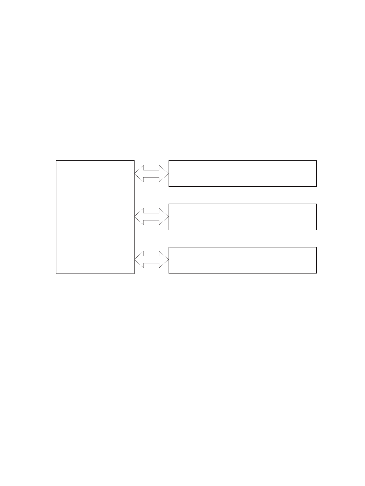
Product block diagram
Figure 1-1 Product block diagram
LASER/SCANNER SYSTEM
ENGINE CONTROL
SYSTEM
IMAGE-FORMATION SYSTEM
PICKUP-AND-FEED SYSTEM
2 Chapter 1 Theory of operation ENWW
Page 18

Sequence of operation
The DC controller in the engine-control system controls the operational sequences of the product. The
table below describes durations and operations for each period of a print operation from when the
product is turned on until the motor stops rotating.
Normal sequence of operation
Table 1-1 Sequence of operation
Name Timing Purpose
WAIT From the time the power switch is turned on, the door
STBY (standby) From the end of the WAIT or LSTR period until either
INTR (initial
rotation)
PRINT From the end of the INTR period until the last sheet
LSTR (last
rotation)
is closed or the product exits Sleep mode until the
product gets ready for a print operation.
a print command is sent or the power switch is turned
off.
From the time a print command is received until the
paper is picked up.
completes the fuser operation.
From the end of the PRINT period until the main motor
stops rotating.
Brings the product to ready state. The product
performs the following during the operations:
Detects the print cartridge
●
Heats the fuser film in the fuser
●
Rotates, and the stops, the main motor
●
Maintains the product in printable condition. The
product performs the following during the operation:
Enters Auto-Off mode if Auto-Off command is
●
received
The product performs the following during the
operations:
Drives the main motor
●
Activates the high-voltage power supply
●
Activates the laser/scanner
●
Warms the fuser heater
●
Forms the image on the photosensitive drum based
on the VIDEO signals from the formatter. Transfers
and fuses the toner image to the paper.
Moves the last printed sheet out of the product. The
product performs the following during the operations:
Stops the main motor
●
Deactivates the high-voltage power supply
●
Deactivates the laser/scanner
●
Deactivates the fuser heater
●
The product enters the INTR period as the LSTR
period is completed, if the formatter sends another
print command.
ENWW Basic operation 3
Page 19

Formatter-control system
The formatter is responsible for the following procedures:
Controlling sleep mode
●
Receiving and processing print data from the various product interfaces
●
Monitoring control-panel functions and relaying product-status information (through the control
●
panel and the network or bidirectional interface)
Developing and coordinating data placement and timing with the DC controller PCA
●
Storing font information
●
Communicating with the host computer through the network or the bidirectional interface
●
The formatter receives a print job from the network or bidirectional interface and separates it into image
information and instructions that control the printing process. The DC controller PCA synchronizes the
image-formation system with the paper-input and -output systems, and then signals the formatter to
send the print-image data.
Sleep mode
NOTE: This product uses an Auto-Off feature for sleep mode.
After a user-specified time, the Auto-Off feature automatically conserves electricity by substantially
reducing power consumption when the product is not printing. After a user-specified time, the product
automatically reduces its power consumption (Auto-Off). The product returns to the ready state when a
button is pressed, a print job is received, or a door is opened. When the product is in Auto-Off mode,
all of the control-panel LEDs and the power button backlight LED are off.
NOTE: Although the product lights are off in Auto-Off mode, the product functions normally when it
receives a print job.
Input/output
The product receives print data primarily from the following:
Hi-Speed USB 2.0 port
●
802.11b/g wireless networking (wireless models only)
●
CPU
The formatter incorporates a 400 MHz Helium processor.
Memory
The random access memory (RAM) on the formatter PCA contains the page, I/O buffers, and the font
storage area. RAM stores printing and font information received from the host system, and can also
serve to temporarily store a full page of print-image data before the data is sent to the print engine.
4 Chapter 1 Theory of operation ENWW
Page 20

Firmware
HP LaserJet Professional P1560 Printer series
●
◦
HP LaserJet Professional P1600 Printer series
●
◦
Memory use
HP LaserJet Professional P1560 Printer series
●
◦
HP LaserJet Professional P1600 Printer series
●
◦
PJL overview
The product has 8 MB of Synchronous DRAM, which is used for run-time firmware imaging
and specific print job information for the print job.
The product has 32 MB of Synchronous DRAM, which is used for run-time firmware imaging
and specific print job information for the print job.
The product has a 2 KB EEPROM and 64 MB of NAND Flash Memory, which is used for
product configuration information and printer driver firmware.
The product has a 8 KB EEPROM and 64 MB of NAND Flash Memory, which is used for
product configuration information and printer driver firmware.
The printer job language (PJL) is an integral part of configuration, in addition to the standard printer
command language (PCL). With standard cabling, the product can use PJL to perform a variety of
functions such as these:
Two-way communication with the host computer through a network connection or a USB
●
connection. The product can inform the host about such things as the control-panel settings, and
the control-panel settings can be changed from the host.
Dynamic I/O switching. The product uses this switching to be configured with a host on each I/O.
●
The product can receive data from more than one I/O simultaneously, until the I/O buffer is full.
This can occur even when the product is offline.
Context-sensitive switching. The product can automatically recognize the personality (PS or PCL)
●
of each job and configure itself to serve that personality.
Isolation of print environment settings from one print job to the next. For example, if a print job is
●
sent to the product in landscape mode, the subsequent print jobs print in landscape mode only if
they are formatted for landscape printing.
LEDM overview
NOTE: HP LaserJet Professional P1600 Printer series
The low-end data model (LEDM) provides one consistent data representation method and defines the
dynamic and capabilities tickets shared between clients and devices, as well as the access protocol,
event, security, and discovery methods.
ACL overview
The advanced control language (ACL) is a language that supports product control and firmware
downloads in printers that support both PJL/PCL and host-based printing. Each sequence of ACL
ENWW Formatter-control system 5
Page 21

commands must be preceded by a unified exit command (UEL) and an @PJL ENTER LANGUAGE=ACL
command. The ACL sequence is always followed by a UEL. Any number of commands can be placed
between the UELs. The only exception to these rules is the download command. If a firmware download
is done, the download command must be the last command in the sequence. It will not be followed by
a UEL.
The firmware searches for the UEL sequence when parsing commands. However, while downloading
binary data such as host-based code or NVRAM data the firmware suspends UEL parsing. To handle
hosts that “disappear” during binary sequences, the firmware times out all ACL command sessions. If
a timeout occurs during a non-download command sequence, it is treated as the receipt of a UEL. If a
timeout occurs during firmware download the product resets.
Control panel
The formatter sends and receives product status and command data to and from the control-panel PCA.
6 Chapter 1 Theory of operation ENWW
Page 22
Engine-control system
The engine-control system coordinates all product functions, according to commands that the formatter
sends. The engine-control system drives the laser/scanner system, the image-formation system, and
the pickup/feed/delivery system.
The engine control system contains the following major components:
Engine-control unit (ECU)
●
DC controller
◦
Low-voltage power supply
◦
High-voltage power supply
●
Fuser control
●
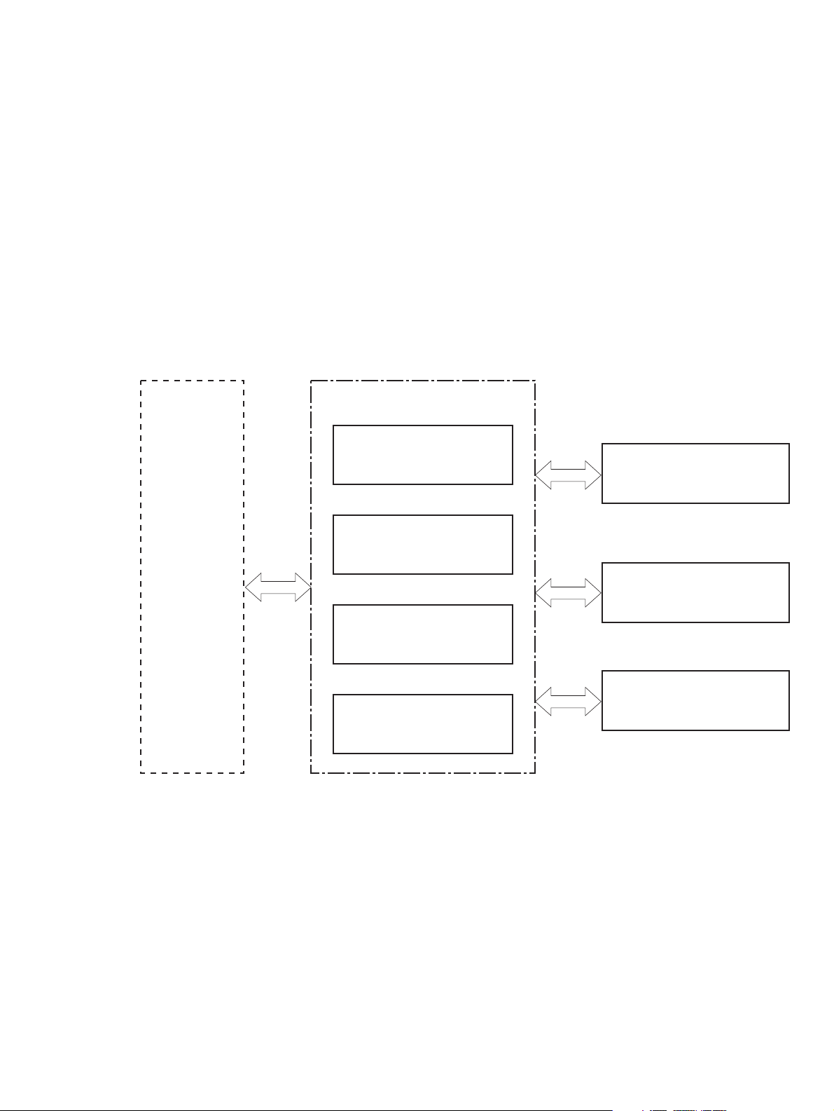
Figure 1-2 Engine-control system
ENGINE CONTROL SYSTEM
DC controller
LASER/SCANNER SYSTEM
Formatter
Low-voltage power supply
IMAGE-FORMATION SYSTEM
High-voltage power supply
MEDIA-FEED SYSTEM
Fuser control
ENWW Engine-control system 7
Page 23
Motors, fans, clutches, solenoids, switches, and sensors
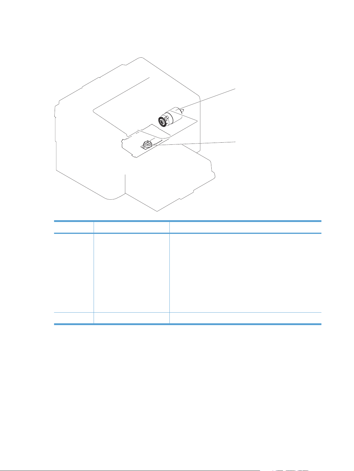
Figure 1-3 Motors
M1
M2
Table 1-2 Motors
Item Description Components driven
M1 Main motor
M2 Scanner motor
Pickup roller
●
Feed roller
●
Photosensitive drum
●
Developing roller
●
Pressure roller
●
Delivery roller
●
Duplex feed roller
●
Scanner mirror
●
8 Chapter 1 Theory of operation ENWW
Page 24
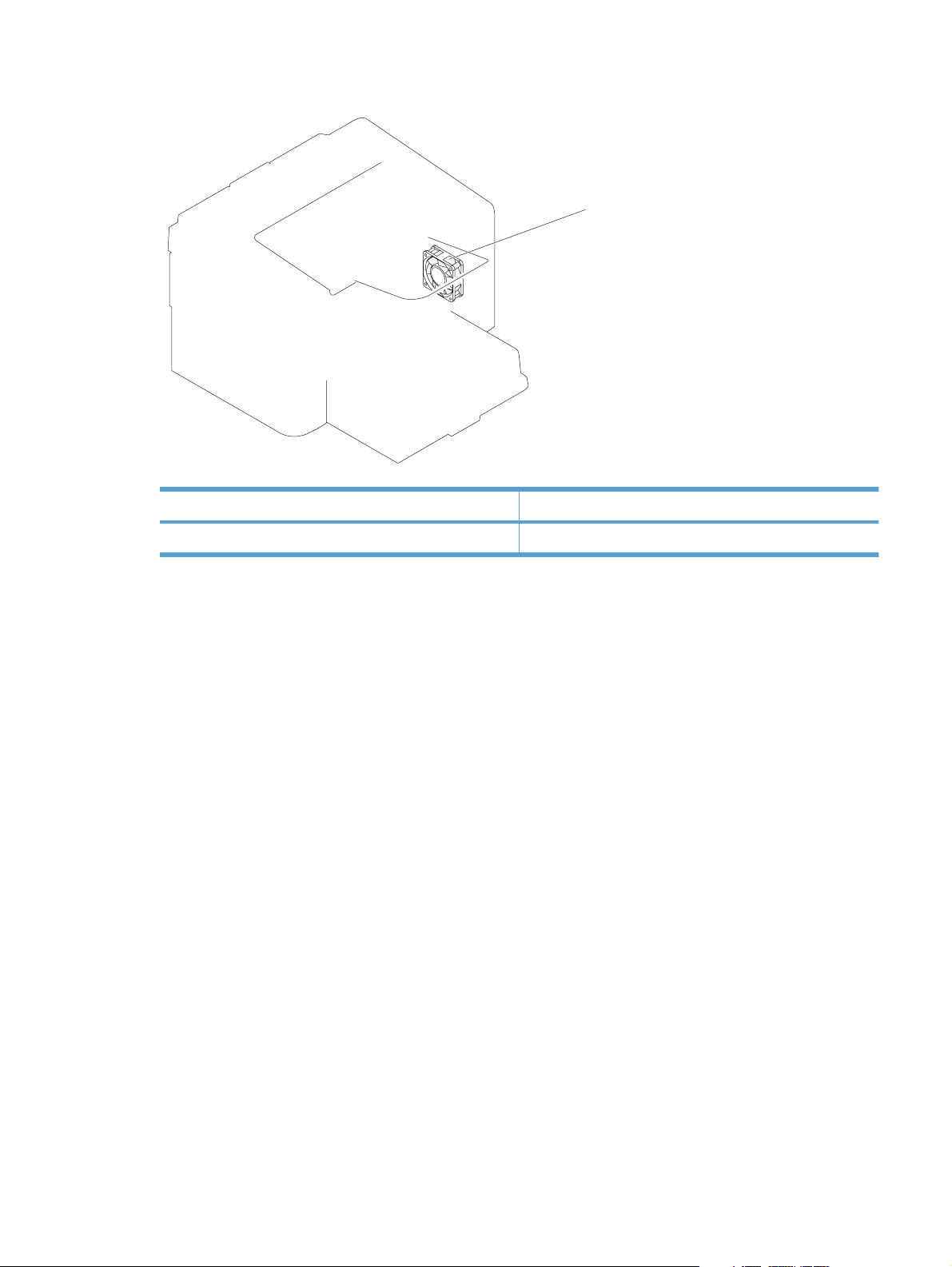
Figure 1-4 Fans
Table 1-3 Fans
Item Description
FM1 Main fan
FM1
ENWW Engine-control system 9
Page 25
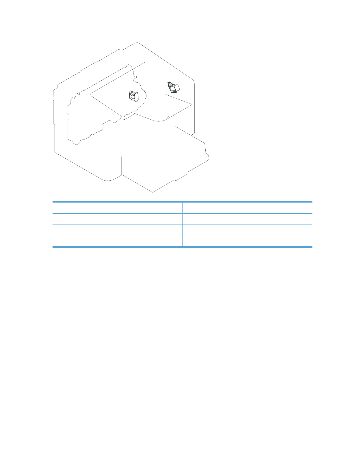
Figure 1-5 Solenoids and clutches
SL1
Table 1-4 Solenoids and clutches
SL2
Item Description
SL1 Pickup solenoid
SL2 Duplex reverse solenoid
NOTE: Duplex models only.
10 Chapter 1 Theory of operation ENWW
Page 26
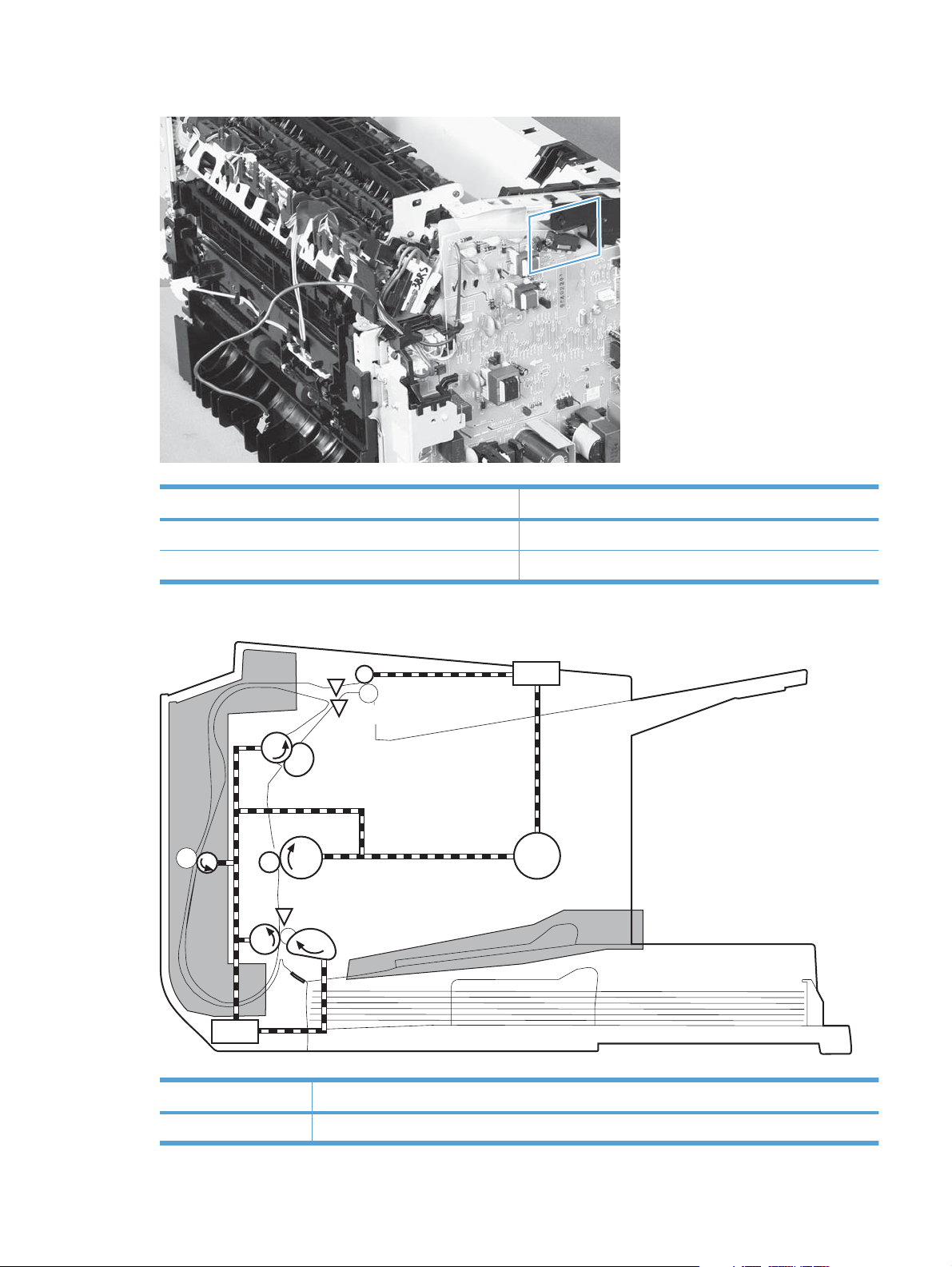
Figure 1-6 Switches
Table 1-5 Switches
Item Description
SW501 Cartridge-door switch
SW502 Power switch; not shown
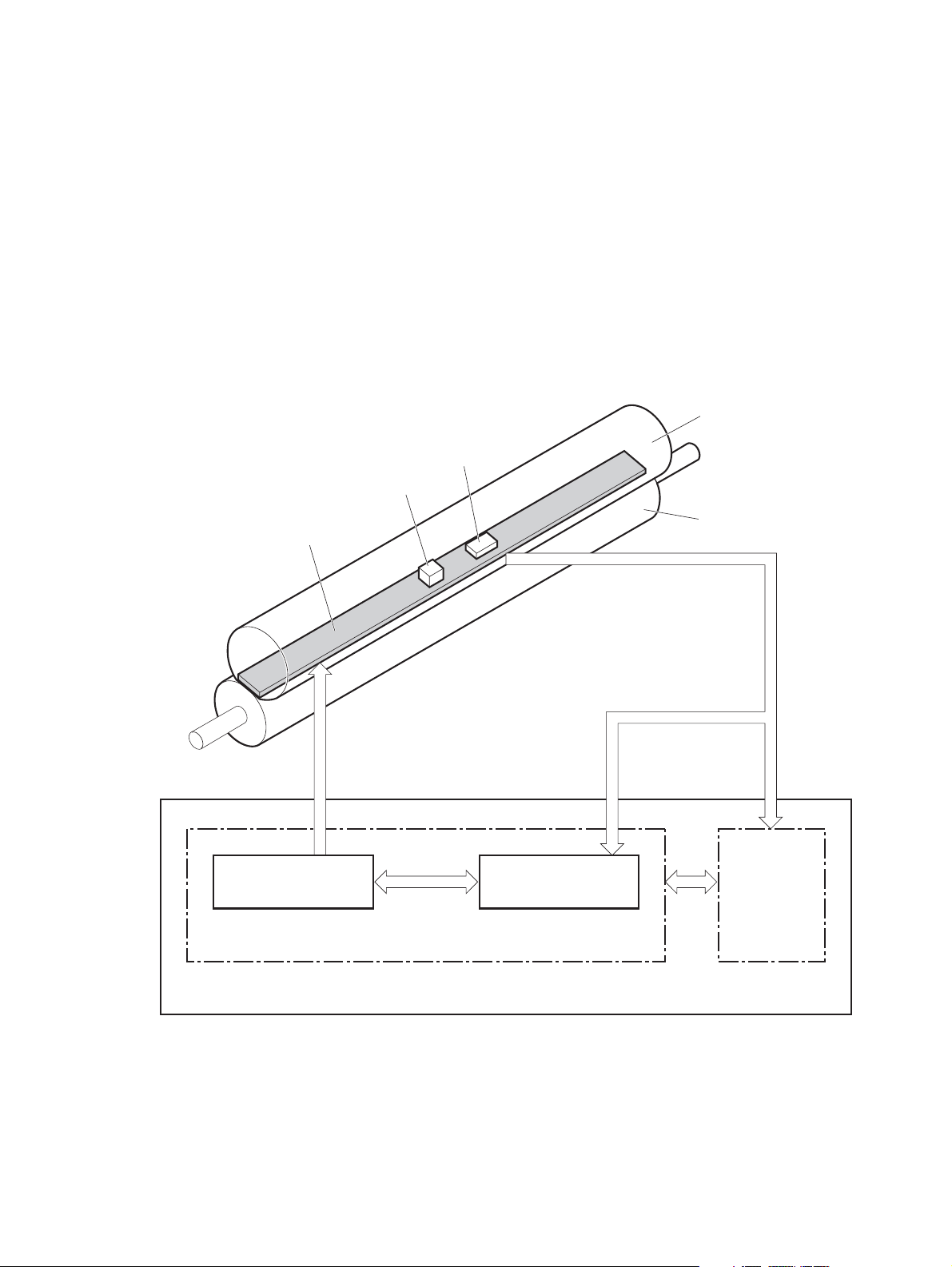
Figure 1-7 Sensors
Table 1-6 Sensors
PS702
PS701
PS751
Item Description
PS701 Fuser delivery sensor
ENWW Engine-control system 11
Page 27

Table 1-6 Sensors (continued)
Item Description
PS702 Media-width sensor
PS751 Top-of-Page (TOP) sensor
PS901 Main-motor rotation-number sensor; not shown
12 Chapter 1 Theory of operation ENWW
Page 28
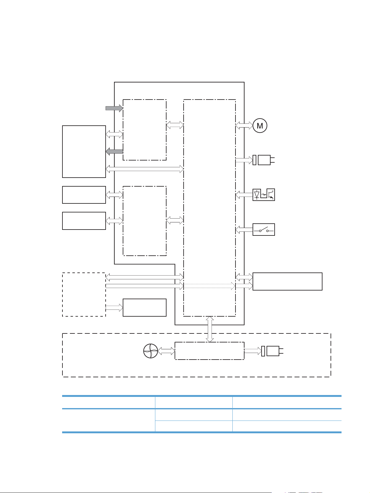
DC controller operations
The DC controller controls the operational sequences of the product systems.
Figure 1-8 DC controller block diagram
AC input
Engine controller
Fuser unit
Transfer roller
Cartridge
Formatter
Low-voltage
power supply
High-voltage
power supply
Motor
Solenoid
Photointerrupter
DC controller
Switch
Laser scanner
Operation panel
Solenoid
Duplex model only
Fan
Duplex connector PCA
Table 1-7 DC controller controlled components
Component Designator Description
Motor M1 Main motor
M2 Scanner motor
ENWW Engine-control system 13
Page 29

Table 1-7 DC controller controlled components (continued)
Component Designator Description
Solenoid SL1 Pickup solenoid
SL2 Duplex reverse solenoid
NOTE: Duplex models only.
Photointerrupter PS701 Fuser delivery sensor
PS702 Media-width sensor
PS751 Top-of-Page (TOP) sensor
PS901 Main-motor rotation-number sensor
Switch SW501 Cartridge-door switch
SW502 Power switch
Fan FM1 Main Fan
14 Chapter 1 Theory of operation ENWW
Page 30
Fuser-control circuit
The fuser-control circuit monitors and controls the temperature in the fuser. The product uses ondemand fusing. The fuser-control circuit consists of the following major components:
Fuser heater (H1); heats the fusing film
●
Thermistor (TH1); detects the fuser temperature (contact type)
●
Thermoswitch (TP1); prevents abnormal temperature rise in the fuser (contact type)
●
Figure 1-9 Fuser control circuit
Fuser film
TH1
TP1
H1
FUSER HEATER CONTROL signal
Fuser heater control
circuit
Fuser control
Pressure roller
FUSER TEMPERATURE signal
Fuser heater safety
circuit
DC controller
Engine controller
ENWW Engine-control system 15
Page 31

Fuser failure detection
The DC controller determines a fuser unit failure, releases the relay to interrupt power supply to the
fuser heater, and notifies the formatter of a failure state when it encounters the following conditions:
Start up failure
●
If the main thermistor does not detect a specified temperature during the start up process of
◦
the heater in the wait period.
If the main thermistor does not detect a specified temperature during the heater temperature
◦
control in the initial rotation period.
Abnormal low temperature
●
If the main thermistor detects an abnormal low temperature of the fuser unit during the printing
◦
operation.
Abnormal high temperature
●
If the main thermistor detects an abnormal high temperature of the fuser unit.
◦
Frequency detection circuit failure
●
If a specified frequency of the FREQUENCY signal is not detected within a specified period
◦
after the product is turned on.
16 Chapter 1 Theory of operation ENWW
Page 32

Fuser temperature control
The fuser temperature control maintains the temperature of the fuser heater at its targeted temperature.
The DC controller monitors the FIXING TEMPERATURE (FSRTH) signals and sends the FIXING
HEATER CONTROL (FSRD) signal according to the detected temperature. The fuser heater control
circuit controls the fuser heater depending on the signal so that the heater remains at the targeted
temperature.
Figure 1-10 Fuser-heater control circuit
AC input
Engine controller
RL101
Fuser heater
control circuit
TP1
Frequency detection
circuit
(220-240V model only)
Relay control
circuit
TH1
Fixing control
Fuser heater
safety circuit
DC controller
FREQSNS
RLYD
FSRD
FSRTH
H1
Fuser film unit
Pressure roller
Fuser unit
ENWW Engine-control system 17
Page 33

Fuser protective function
The protective function detects an abnormal temperature rise of the fuser unit and interrupts power
supply to the fuser heater.
The following three protective components prevent an abnormal temperature rise of the fuser heater:
DC controller
●
The DC controller interrupts power supply to the fuser heater when it detects an abnormal
◦
temperature of the fuser heater.
Fuser heater safety circuit
●
The fuser heater safety circuit interrupts power supply to the fuser heater when the detected
◦
temperature of the main thermistor is abnormal.
Thermoswitch
●
The contact of the thermal fuse is broken to interrupt power supply to the fuser heater when
◦
the thermal fuse detects an abnormal temperature of the fuser heater.
Pressure roller cleaning
The pressure roller cleaning process is initiated by the formatter. The process removes toner that has
accumulated on the pressure roller by transferring it to a sheet of paper.
The product feeds a sheet of paper after receiving the cleaning command from the formatter.
●
Main motor rotation is stopped when the trailing edge of the paper passes through the transfer
●
roller.
The main motor rotation is repeatedly started and then stopped. The fuser heater is turned on and
●
then off at the same interval as main motor rotation.
Toner adhered to the pressure roller is fused to the paper.
●
The paper is ejected from the product.
●
18 Chapter 1 Theory of operation ENWW
Page 34

Low-voltage power supply
The low-voltage power supply (LVPS) converts ac input voltage to dc voltage. The LVPS has two fuses
on the PCA. The LVPS 24 V output is interrupted to the fuser and the high-voltage power supply if the
cartridge-door interlock switch (SW501) is in the off position (cover open).
WARNING! The product power switch only interrupts dc voltage from the LVPS. The ac voltage is
present in the product when the power cord is plugged into a power receptacle and the power switch is
in the off position. You must unplug the product power cord before servicing the product.
Figure 1-11 Low-voltage power supply (LVPS)
AC input
Rectifying
circuit
+24V
generation
circuit
Low-voltage power supply
Fuse (FU201)
Cartridge-door switch
Engine controller
Fuse (FU101)
(SW501)
+24U
Frequency
detection circuit
(220-240V model only)
+24V ON/OFF
circuit
DC controller
Fuser unit
High-voltage
power supply
FREQSNS
BSTSIG
+24V
24VON
+24P
Protection
circuit
+5V
generation
circuit
+3.3V
generation
circuit
+3.3V ON/OFF
circuit
+3.3R
Formatter
+5V
+5R
+3.3V
+3.3VON
+3.3UON
+3.3U
Power switch
(SW502)
ENWW Engine-control system 19
Page 35

Overcurrent/overvoltage protection
The low-voltage power supply has a protective function against overcurrent and overvoltage to prevent
failures in the power supply circuit. If an overcurrent or overvoltage condition occurs, the system
automatically cuts off the output voltage.
If the dc power is not being supplied from the low-voltage power supply, the protective function might
be running. In such case, turn off the power switch and unplug the power cord. Do not plug in the power
cord or turn on the power switch again until the cause is found.
WARNING! If you believe the overcurrent or overvoltage protection circuits have been activated, do
not plug in the product power cord or turn on the product power until the cause of the failure is found
and corrected.
In addition, two fuses in the low-voltage power supply protect against overcurrent. If overcurrent flows
into the ac line, the fuses melt and cut off the power distribution.
20 Chapter 1 Theory of operation ENWW
Page 36

High-voltage power supply
The high-voltage power supply (HVPS) applies biases to the following components:
Primary charging roller
●
Developing roller
●
Transfer roller
●
Figure 1-12 High-voltage power supply
Engine controller
DC controller
High-voltage power supply
Primary
charging bias
circuit
Developing
bias circuit
Transfer bias
circuit
To primary charging roller
To developing roller
Cartridge
Photosensitive drum
Transfer roller
ENWW Engine-control system 21
Page 37

Laser/scanner system
The laser/scanner system receives VIDEO signals from the ECU and formatter and converts the signals
into latent images on the photosensitive drum.
The main components of the laser/scanner are the laser unit and the scanner motor unit. The DC
controller sends signals to the laser/scanner to control the functions of these components.
Figure 1-13 Laser/scanner system
Laser unit
BD sensor
Photosensitive drum
Scanning mirror
Scanner motor unit
BDI signal
VIDEO signal
LASER CONTROL signal
SCANNER MOTOR CONTROL signal
DC controlle r
Engine controller
Formatter
22 Chapter 1 Theory of operation ENWW
Page 38

Laser failure detection
The DC controller determines an optical unit failure and notifies the formatter, if the laser/scanner
encounters the following conditions:
The scanner motor does not reach a specified rotation within a specified period of the scanner
●
motor start up.
The rotation of the scanner motor is out of specified range for a specified period during the scanner
●
motor drive.
The BD interval is out of a specified value during a print operation.
●
ENWW Engine-control system 23
Page 39

Image-formation system
Electrophotographic process
The electrophotographic process forms an image on the paper. Following are the major components
used in the process:
Print cartridge
●
Transfer roller
●
Fuser
●
Laser/scanner
●
High-voltage power supply
●
The DC controller uses the laser/scanner and HVPS to form the toner image on the photosensitive drum.
The image is transferred to the paper and then fused onto the paper.
Figure 1-14 Electrophotographic process block diagram (1 of 2)
Transfer roller
Cartridge
Laser scanner
High-voltage power supply
DC controller
Engine controller
The DC controller rotates the main motor to drive the following components:
Photosensitive drum
●
Developing drum
●
Primary charging roller (follows the rotation of the photosensitive drum)
●
Transfer roller (follows the rotation of the photosensitive drum)
●
24 Chapter 1 Theory of operation ENWW
Page 40

Figure 1-15 Electrophotographic process block diagram (2 of 2)
Primary charging roller
Developing roller
Main motor
Transfer roller
Cartridge
Photosensitive drum
DC controller
Engine controller
ENWW Image-formation system 25
Page 41

Image formation process
Each of the following process function independently and must be coordinated with the other product
processes. Image formation consists of the following processes:
Latent-image formation block
●
Step 1: primary charging
◦
Step 2: laser-beam exposure
◦
Developing block
●
Step 3: developing
◦
Transfer block
●
Step 4: transfer
◦
Step 5: separation
◦
Fusing block
●
Step 6: fusing
◦
Drum cleaning block
●
Step 7: drum cleaning
◦
Figure 1-16 Image formation process
26 Chapter 1 Theory of operation ENWW
Page 42

Latent-image formation stage
During the latent-image formation stage, the laser/scanner forms an invisible image on the
photosensitive drum in the print cartridge.
Primary charging
Step 1: DC and AC biases are applied to the primary charging roller, which transfers a uniform negative
potential to the photosensitive drum.
Figure 1-17 Primary charging
Primary charging roller
Photosensitive drum
Laser beam exposure
DC bias
Step 2: The laser beam scans the photosensitive drum to neutralize negative charges on parts of the
drum surface. An electrostatic latent image is formed on the drum where negative charges were
neutralized.
Figure 1-18 Laser beam exposure
Laser beam
Unexposed area Exposed area
ENWW Image-formation system 27
Page 43

Developing stage
Print cartridge
Step 3: In the print cartridge, the developing cylinder transfers toner onto the electrostatic latent image
on the photosensitive drum.
Figure 1-19 Print cartridge
Blade
Developing cylinder
Exposed area
Unexposed area
Unexposed area
Exposed area
Photosensitive drum
AC bias
DC bias
Toner acquires a negative charge from the friction that occurs when the developing roller rotates against
the developing blade. The developing bias is applied to the developing roller to make a potential
difference between the developing roller and the photosensitive drum. The negatively charged toner is
attracted to the latent image on the photosensitive drum because the drum surface has a higher
potential.
28 Chapter 1 Theory of operation ENWW
Page 44

Transfer stage
Step 4: The transfer charging roller, to which a DC positive bias is applied, imparts a positive charge
on the paper. When the page comes in contact with the photosensitive drum, the toner is transferred to
the paper.
Figure 1-20 Transfer
Transfer roller
Step 5: The elasticity of the paper causes its separation from the photosensitive drum. A static charge
eliminator aids separation by weakening any electrostatic adhesion.
Figure 1-21 Separation
Photosensitive
drum
Media
DC bias
Static charge eliminator
Fusing stage
Step 6: The DC negative bias applied to the fusing film strengthens the holding force of the toner on the
paper and prevents the toner from scattering.
Photosensitive
drum
Media
Transfer roller
ENWW Image-formation system 29
Page 45

The product uses an on-demand fuser method. The toner image is permanently affixed to the paper by
heat and pressure.
Figure 1-22 Fusing
Cleaning stage
Step 7: The cleaning blade scrapes the residual toner off of the photosensitive drum and deposits it into
the waste toner case.
Figure 1-23 Drum cleaning
Cleaning blade
Fuser heater
Fuser film
Toner
Media
Pressure roller
Waste toner container
Photosensitive
drum
30 Chapter 1 Theory of operation ENWW
Page 46

Pickup, feed, and delivery system
The media feed system picks up, feeds, and delivers the page.
Figure 1-24 Pickup, feed, and delivery system block diagram
Duplex feed unit
Delivery roller
Pressure roller
Fuserfilm
Transfer roller
Duplex
feed roller
Separation pad
Photosensitive drum
Feed roller
Pickup roller
Simplex media path
Duplex media path
Single-sheet-feed slot
ENWW Pickup, feed, and delivery system 31
Page 47

Photo sensors and switches
NOTE: The illustration in this section also shows the product motor, photo sensors, and solenoid. The
power switch is not shown.
Figure 1-25 Photo sensors, motor, and solenoid
SL1
PS702
PS751
SL2
PS701
M1
Table 1-8 Photo sensors, motor, and solenoid
Item Description
M1 Main motor
SL1 Pickup solenoid
32 Chapter 1 Theory of operation ENWW
Page 48

Table 1-8 Photo sensors, motor, and solenoid (continued)
Item Description
SL2 Duplex feed solenoid
NOTE: Duplex models only.
PS701 Fuser delivery sensor
PS702 Media-width sensor
PS751 TOP sensor
ENWW Pickup, feed, and delivery system 33
Page 49

Main-input tray or priority input slot
Jam detection
The product uses the following sensors to detect the presence of paper and to check for jams. The page
must pass each sensor within a specified time.
NOTE: To find the following components, see Photo sensors and switches on page 32.
PS701; fuser delivery sensor
●
PS702; TOP sensor
●
NOTE: The product automatically ejects paper if the TOP sensor detects residual paper within
the product when the power is turned on or the door is closed.
The product detects the following jams:
Pickup stationary jam
●
Delivery delay jam
●
Delivery stationary jam
●
Fuser wrapping jam
●
Door open jam
●
Residual media jam
●
Duplex reverse delay jam (duplex models only)
●
Duplex reverse stationary jam (duplex models only)
●
Duplex re-pickup delay jam (duplex models only)
●
34 Chapter 1 Theory of operation ENWW
Page 50

2 Removal and replacement
Introduction
●
Removal and replacement strategy
●
Electrostatic discharge
●
Required tools
●
Before performing service
●
After performing service
●
Post-service test
●
Parts removal order
●
Pickup roller
●
Separation pad
●
Transfer roller
●
Covers
●
Main assemblies
●
ENWW 35
Page 51

Introduction
This chapter describes the removal and replacement of field-replaceable units (FRUs) only.
Replacing FRUs is generally the reverse of removal. Occasionally, notes and tips are included to provide
directions for difficult or critical replacement procedures.
HP does not support repairing individual subassemblies or troubleshooting to the component level.
Note the length, diameter, color, type, and location of each screw. Be sure to return each screw to its
original location during reassembly.
Incorrectly routed or loose wire harnesses can interfere with other internal components and can become
damaged or broken. Frayed or pinched harness wires can be difficult to find. When replacing wire
harnesses, always use the provided wire loops, lance points, or wire-harness guides and retainers.
Removal and replacement strategy
WARNING! Turn the product off, wait 5 seconds, and then remove the power cord before attempting
to service the product. If this warning is not followed, severe injury can result, in addition to damage to
the product. The power must be on for certain functional checks during troubleshooting. However,
disconnect the power supply during parts removal.
Never operate or service the product with the protective cover removed from the laser/scanner
assembly. The reflected beam, although invisible, can damage your eyes.
The sheet-metal parts can have sharp edges. Be careful when handling sheet-metal parts.
CAUTION: Do not bend or fold the flat flexible cables (FFCs) during removal or installation. Also, do
not straighten pre-folds in the FFCs. You must fully seat all FFCs in their connectors. Failure to fully
seat an FFC into a connector can cause a short circuit in a PCA.
NOTE: To install a self-tapping screw, first turn it counterclockwise to align it with the existing thread
pattern, and then carefully turn it clockwise to tighten. Do not overtighten. If a self-tapping screw-hole
becomes stripped, repair the screw-hole or replace the affected assembly.
TIP: For clarity, some photos in this chapter show components removed that would not be removed
to service the product. If necessary, remove the components listed at the beginning of a procedure
before proceeding to service the product.
36 Chapter 2 Removal and replacement ENWW
Page 52

Electrostatic discharge
CAUTION: Some parts are sensitive to electrostatic discharge (ESD). Look for the ESD reminder
when removing product parts. Always perform service work at an ESD-protected workstation or mat, or
use an ESD strap. If an ESD workstation, mat, or strap is not available, ground yourself by touching the
sheet-metal chassis before touching an ESD-sensitive part.
Protect the ESD-sensitive parts by placing them in ESD pouches when they are out of the product.
Required tools
#2 Phillips screwdriver with a magnetic tip and a 152-mm (6-inch) shaft length
●
Small flat-blade screwdriver
●
Needle-nose pliers
●
ESD mat or ESD strap (if one is available)
●
Penlight (optional)
●
CAUTION: Always use a Phillips screwdriver (callout 1). Do not use a pozidrive screwdriver (callout 2)
or any motorized screwdriver. These can damage screws or screw threads.
Figure 2-1 Phillips and pozidrive screwdriver comparison
Before performing service
Remove all paper from the product.
●
Turn off the power using the power switch.
●
Unplug the power cable and interface cable or cables.
●
Place the product on an ESD workstation or mat, or use an ESD strap (if one is available). If an
●
ESD workstation, mat, or strap is not available, ground yourself by touching the sheet-metal chassis
before touching an ESD-sensitive part.
Remove the print cartridge.
●
ENWW Electrostatic discharge 37
Page 53

After performing service
Plug in the power cable.
●
Reinstall the print cartridge.
●
Load paper in the product.
●
Post-service test
Perform the following test to verify that the repair or replacement was successful.
Print-quality test
1. Verify that you have completed the necessary reassembly steps.
2. Make sure that the tray contains clean, unmarked paper.
3. Attach the power cord and interface cable or interface cables, and then turn on the product.
4. Verify that the expected startup sounds occur.
5. Print a configuration page, and then verify that the expected printing sounds occur.
6. Print a demo page, and then verify that the print quality is as expected.
7. Send a print job from the host computer, and then verify that the output meets expectations.
8. Clean the outside of the product with a damp cloth.
38 Chapter 2 Removal and replacement ENWW
Page 54

Parts removal order
Figure 2-2 Parts removal order
Pickup roller
Separation pad
Transfer roller
Duplex door (duplex models)
Main input tray and output tray
Left and right covers
Formatter PCA
Cartridge door
Left and right covers
Duplex frame (duplex models)
Control panel
Rear cover (simplex models)
Front cover
Laser/scanner asssembly
Main motor
Face-down cover
Rear cover (simplex models),
or Duplex door (duplex models)
and Duplex frame (duplex models)
Pickup assembly
Fuser
Pickup solenoid
Engine controller PCA
Duplex-reverse solenoid (duplex models)
Main fan (duplex models)
Duplex-connector PCA (duplex models)
ENWW Parts removal order 39
Page 55

Pickup roller
CAUTION: Do not touch the sponge portion of the roller. Skin oils can cause paper handling problems.
1. Release two tabs.
Figure 2-3 Remove the pickup roller (1 of 2)
2. Rotate the roller away from the product to remove it.
Figure 2-4 Remove the pickup roller (2 of 2)
40 Chapter 2 Removal and replacement ENWW
Page 56

Separation pad
CAUTION: Do not touch the sponge portion of the pad. Skin oils can cause paper handling problems.
1. Place the product rear-side up to access the separation pad assembly.
CAUTION: Dirt and debris can scratch the product covers. Place the product on a cloth or other
clean surface.
2. Remove two screws (callout 1) and then remove the separation pad assembly (callout 2).
Figure 2-5 Remove the separation pad assembly
1
2
ENWW Separation pad 41
Page 57

Transfer roller
CAUTION: Do not touch the sponge portion of the roller. Skin oils can cause print quality problems.
1. Open the print-cartridge door.
2. Release two tabs (callout 1), and then remove the transfer roller (callout 2).
Figure 2-6 Remove the transfer roller
2
1
42 Chapter 2 Removal and replacement ENWW
Page 58

Covers
Main-input tray
Open the tray (callout 1), release two tabs (callout 2), and then remove the tray.
Figure 2-7 Remove the tray
1
2
ENWW Covers 43
Page 59

Output bin tray extension
Release two pins (callout 1), and then remove the tray extension (callout 2)
Figure 2-8 Remove the output bin tray extension
1
2
44 Chapter 2 Removal and replacement ENWW
Page 60

Left cover, simplex product
Before proceeding, remove the following components:
Main-input tray. See
●
Output bin tray extension. See
●
Main-input tray on page 43.
Output bin tray extension on page 44.
Remove the left cover, simplex product
1. Remove one screw (callout 1).
Figure 2-9 Remove the left cover, simplex product (1 of 4)
1
2. Release one tab (callout 1) at the bottom edge of the cover.
Figure 2-10 Remove the left cover, simplex product (2 of 4)
1
ENWW Covers 45
Page 61

3. Release one tab (callout 1) at the top edge of the cover.
Figure 2-11 Remove the left cover, simplex product (3 of 4)
1
4. Rotate the back edge of the cover away from the product, and then remove the cover (callout 1).
Figure 2-12 Remove the left cover, simplex product (4 of 4)
1
46 Chapter 2 Removal and replacement ENWW
Page 62

Left cover, duplex product
Main-input tray. See
●
Output bin tray extension. See
●
Main-input tray on page 43.
Output bin tray extension on page 44.
Remove the left cover, duplex product
1. Remove one screw (callout 1).
Figure 2-13 Remove the left cover, duplex product (1 of 5)
1
2. Open the duplex door (callout 1), and then release two tabs (callout 2).
Figure 2-14 Remove the left cover, duplex product (2 of 5)
2
1
ENWW Covers 47
Page 63

3. Release one tab (callout 1) at the bottom edge of the cover.
Figure 2-15 Remove the left cover, duplex product (3 of 5)
1
4. Release one tab (callout 1) at the top edge of the cover.
Figure 2-16 Remove the left cover, duplex product (4 of 5)
1
48 Chapter 2 Removal and replacement ENWW
Page 64

5. Rotate the back edge of the cover away from the product, and then remove the cover (callout 1).
Figure 2-17 Remove the left cover, duplex product (5 of 5)
1
ENWW Covers 49
Page 65

Right cover, simplex product
Before proceeding, remove the following components:
Main-input tray. See
●
Output bin tray extension. See
●
Main-input tray on page 43.
Output bin tray extension on page 44.
Remove the right cover, simplex product
1. Remove one screw (callout 1).
Figure 2-18 Remove the right cover, simplex product (1 of 4)
1
2. Release one tab (callout 1) at the bottom edge of the cover.
Figure 2-19 Remove the right cover, simplex product (2 of 4)
1
50 Chapter 2 Removal and replacement ENWW
Page 66

3. Slide the cover toward the front of the product to release it, and then remove the cover (callout 1).
Figure 2-20 Remove the right cover, simplex product (4 of 4)
1
ENWW Covers 51
Page 67

Right cover, duplex product
Main-input tray. See
●
Output bin tray extension. See
●
Main-input tray on page 43.
Output bin tray extension on page 44.
Remove the right cover, duplex product
1. Remove one screw (callout 1).
Figure 2-21 Remove the right cover, duplex product (1 of 5)
1
2. Open the duplex door (callout 1), and then release two tabs (callout 2).
Figure 2-22 Remove the right cover, duplex product (2 of 5)
1
52 Chapter 2 Removal and replacement ENWW
Page 68

3. Release one tab (callout 1) at the bottom edge of the cover.
Figure 2-23 Remove the right cover, duplex product (3 of 5)
1
4. Open the cartridge door (callout 1), and then release one tab (callout 2) at the top edge of the cover.
Figure 2-24 Remove the right cover, duplex product (4 of 5)
1
2
ENWW Covers 53
Page 69

5. Slide the cover toward the front of the product to release it, and then remove the cover (callout 1).
Figure 2-25 Remove the right cover, duplex product (5 of 5)
1
54 Chapter 2 Removal and replacement ENWW
Page 70

Duplex door, duplex product
Open the duplex door (callout 1), release two tabs (callout 2), and then remove the door.
Figure 2-26 Remove the duplex door, duplex product
2
1
ENWW Covers 55
Page 71

Duplex frame, duplex product
Before proceeding, remove the following components:
Left cover. See
●
Right cover. See
●
Duplex door. See
●
Remove the duplex frame
1. Remove four screws (callout 1).
Figure 2-27 Remove the duplex frame (1 of 2)
Left cover, duplex product on page 47.
Right cover, duplex product on page 52.
Duplex door, duplex product on page 55
1
2. Release three tabs (callout 1), and then remove the duplex frame (callout 2).
Figure 2-28 Remove the duplex frame (2 of 2)
2
1
56 Chapter 2 Removal and replacement ENWW
Page 72

Cartridge door
1. Open the cartridge door, and then release two tabs (callout 1) on the right-side link arms.
Figure 2-29 Remove the cartridge door (1 of 3)
2. Release one tab (callout 1) on the left-side link arm.
1
Figure 2-30 Remove the cartridge door (2 of 3)
1
ENWW Covers 57
Page 73

3. Release two pins (callout 1), and then remove the cartridge door (callout 2).
Figure 2-31 Remove the cartridge door (3 of 3)
2
1
58 Chapter 2 Removal and replacement ENWW
Page 74

Control panel
1. Remove the left cover. See Left cover, simplex product on page 45 or Left cover, duplex product
on page 47.
2. Open the cartridge door, and then remove two screws (callout 1).
Figure 2-32 Remove the control panel (1 of 3)
1
3. Disconnect one connector (callout 1).
Figure 2-33 Remove the control panel (2 of 3)
1
ENWW Covers 59
Page 75

4. Release one tab (callout 1), and then remove the control panel (callout 2).
Figure 2-34 Remove the control panel (3 of 3)
2
1
60 Chapter 2 Removal and replacement ENWW
Page 76

Front cover
Before proceeding, remove the following components:
Main-input tray. See
●
Output bin tray extension. See
●
Left cover. See
●
Right cover. See
●
on page 52.
Control panel. See
●
Remove the front cover
1. Release one tab (callout 1).
Figure 2-35 Remove the front cover (1 of 3)
Main-input tray on page 43.
Output bin tray extension on page 44.
Left cover, simplex product on page 45 or Left cover, duplex product on page 47.
Right cover, simplex product on page 50 or Right cover, duplex product
Control panel on page 59.
1
ENWW Covers 61
Page 77

2. Release one tab (callout 1).
Figure 2-36 Remove the front cover (2 of 3)
1
3. Remove the front cover (callout 1).
Figure 2-37 Remove the front cover (3 of 3)
1
62 Chapter 2 Removal and replacement ENWW
Page 78

Rear cover, simplex product
Before proceeding, remove the following components:
Main-input tray. See
●
Output bin tray extension. See
●
Left cover. See
●
Right cover. See
●
Cartridge door. See
●
Control panel. See
●
Main-input tray on page 43.
Output bin tray extension on page 44.
Left cover, simplex product on page 45.
Right cover, simplex product on page 50.
Cartridge door on page 57.
Control panel on page 59.
Remove the rear cover, simplex product
1. Remove one screw (callout 1).
Figure 2-38 Remove the rear cover, simplex product (1 of 3)
1
ENWW Covers 63
Page 79

2. Release two tabs (callout 1).
Figure 2-39 Remove the rear cover, simplex product (2 of 3)
1
3. Rotate the bottom of the rear cover (callout 1) away from the product to remove it.
Figure 2-40 Remove the rear cover, simplex product (2 of 3)
1
64 Chapter 2 Removal and replacement ENWW
Page 80

Face-down cover
Before proceeding, remove the following components:
Main-input tray. See
●
Output bin tray extension. See
●
Left cover. See
●
Right cover. See
●
on page 52.
Cartridge door. See
●
Control panel. See
●
Front cover. See
●
Left cover, simplex product on page 45 or Left cover, duplex product on page 47.
Right cover, simplex product on page 50 or Right cover, duplex product
Cartridge door on page 57.
Control panel on page 59.
Front cover on page 61.
Remove the face-down cover
1. Remove two screws (callout 1).
CAUTION: The upper-cartridge door arms (callout 2) can become easily be dislodged from the
lower arms. Do not lose the upper-cartridge door arms while servicing the product.
Figure 2-41 Remove the face-down cover (1 of 2)
Main-input tray on page 43.
Output bin tray extension on page 44.
2
1
ENWW Covers 65
Page 81

2. Lift the cover up and off the product to remove it.
Figure 2-42 Remove the face-down cover (2 of 2)
66 Chapter 2 Removal and replacement ENWW
Page 82

Main assemblies
NOTE: Some photos in this section show components that might not be installed or removed from
your product; however, the procedures for replacement and repair in this chapter are correct for your
product.
Formatter PCA
1. Remove the left cover. See Left cover, simplex product on page 45 or Left cover, duplex product
on page 47.
2. Disconnect one FFC (callout 1) and one connector (callout 2).
Figure 2-43 Remove the formatter PCA (1 of 2)
2
3. Remove three screws (callout 1), and then remove the formatter PCA.
Figure 2-44 Remove the formatter PCA (2 of 2)
1
1
ENWW Main assemblies 67
Page 83

Laser/scanner assembly
Before proceeding, remove the following components:
Main-input tray. See
●
Output bin tray extension. See
●
Left cover. See
●
Right cover. See
●
on page 52.
Control panel. See
●
Front cover. See
●
Main-input tray on page 43.
Left cover, simplex product on page 45 or Left cover, duplex product on page 47.
Right cover, simplex product on page 50 or Right cover, duplex product
Control panel on page 59.
Front cover on page 61.
Remove the laser/scanner assembly
1. Release one tab (callout 1), and then remove the holder (callout 2).
Figure 2-45 Remove the laser/scanner assembly (1 of 5)
1
Output bin tray extension on page 44.
2
68 Chapter 2 Removal and replacement ENWW
Page 84

2. Remove four screws (callout 1), and then remove the scanner cover (callout 2) and the sheet-metal
plate (callout 3) together.
CAUTION: The scanner cover (callout 2) and sheet-metal plate (callout 3) can be easily
separated. Do not lose the plate while servicing the product.
TIP: When the cover is reinstalled, make sure that the black screws (callout 4) are installed in
the correct screw holes.
Figure 2-46 Remove the laser/scanner assembly (2 of 5)
4
1
2
3. Disconnect one FFC (callout 1), and then remove four screws (callout 2).
Figure 2-47 Remove the laser/scanner assembly (3 of 5)
3
2
1
ENWW Main assemblies 69
Page 85

4. Remove the dust-proof sponge (callout 1).
Figure 2-48 Remove the laser/scanner assembly (4 of 5)
1
5. Disconnect one connector (callout 1), and then remove the laser/scanner assembly (callout 2).
Figure 2-49 Remove the laser/scanner assembly (5 of 5)
1
2
70 Chapter 2 Removal and replacement ENWW
Page 86

Reinstall the laser/scanner assembly
When the holder is reinstalled (callout 1), make sure that the lever arm (callout 2) is correctly
▲
positioned in the slot in the holder.
Figure 2-50 Reinstall the laser/scanner assembly
1
2
ENWW Main assemblies 71
Page 87

Pickup assembly
Before proceeding, remove the following components:
Separation pad. See
●
Main-input tray. See
●
Output bin tray extension. See
●
Left cover. See
●
Right cover. See
●
on page 52.
Duplex frame. See
●
NOTE: Duplex models only.
Cartridge door. See
●
Rear cover or duplex door. See
●
product on page 55.
Face-down cover. See
●
Main-input tray on page 43.
Left cover, simplex product on page 45 or Left cover, duplex product on page 47.
Right cover, simplex product on page 50 or Right cover, duplex product
Duplex frame, duplex product on page 56.
Cartridge door on page 57
Remove the pickup assembly
1. Duplex models only: Release two tabs (callout 1), and then remove the duplex reverse guide
(callout 2).
Separation pad on page 41.
Output bin tray extension on page 44.
Rear cover, simplex product on page 63 or Duplex door, duplex
Face-down cover on page 65.
Figure 2-51 Remove the pickup assembly (1 of 10)
1
2
72 Chapter 2 Removal and replacement ENWW
Page 88

2. Remove two screws (callout 1), and then remove the sheet-metal corner brace (callout 2).
Figure 2-52 Remove the pickup assembly (2 of 10)
2
1
3. Remove one FFC (callout 1), remove three screws (callout 2), and then remove the formatter
(callout 3).
Figure 2-53 Remove the pickup assembly (3 of 10)
3
2
1
ENWW Main assemblies 73
Page 89

4. Remove three screws (callout 1), and then remove the sheet-metal plate (callout 2).
Figure 2-54 Remove the pickup assembly (4 of 10)
2
1
5. Disconnect one connector (callout 1), and then release the wire harness (callout 2) from the guide
(callout 3).
Figure 2-55 Remove the pickup assembly (5 of 10)
2
3
1
74 Chapter 2 Removal and replacement ENWW
Page 90

6. Disconnect three connectors (callout 1), and then remove the wire harness (callout 2) from the
guide (callout 3).
Reinstallation tip When the pickup assembly is reinstalled, place these wire harnesses in the
guide first, and then the wire harness from the ground connector in the previous step. This ensures
that the harnesses are long enough for the connectors to reach the engine controller PCA.
Figure 2-56 Remove the pickup assembly (6 of 10)
2
3
1
7. Remove one bushing (callout 1).
Figure 2-57 Remove the pickup assembly (7 of 10)
1
ENWW Main assemblies 75
Page 91

8. Remove one screw with washer (callout 1).
Figure 2-58 Remove the pickup assembly (8 of 10)
1
9. Remove six screws (callout 1), and then remove the pickup assembly (callout 2).
CAUTION: The ground spring on the assembly is not captive. Do not lose the spring when the
assembly is removed. See
Reinstall the pickup assembly on page 78.
Figure 2-59 Remove the pickup assembly (9 of 10)
1
2
76 Chapter 2 Removal and replacement ENWW
Page 92

10. Duplex models only: Remove one gear (callout 1) from the pickup assembly (callout 2).
CAUTION: The gear is not captive. Do not lose the gear while servicing the product.
Figure 2-60 Remove the pickup assembly (10 of 10)
2
1
ENWW Main assemblies 77
Page 93

Reinstall the pickup assembly
1. Make sure that the pickup assembly ground spring is correctly positioned when the assembly is
reinstalled.
Figure 2-61 Reinstall the pickup assembly (1 of 4; correct ground spring position)
Figure 2-62 Reinstall the pickup assembly (2 of 4; incorrect ground spring position)
78 Chapter 2 Removal and replacement ENWW
Page 94

2. Push down the lift plate before installing the pickup assembly.
TIP: Reach in from the front of the product to push and hold the plate down as the pickup unit is
installed.
Figure 2-63 Reinstall the pickup assembly (3 of 4; lift plate in raised position)
Figure 2-64 Reinstall the pickup assembly (4 of 4; lift plate in lowered position)
ENWW Main assemblies 79
Page 95

Fuser
Before proceeding, remove the following components:
Main-input tray. See
●
Output bin tray extension. See
●
Left cover. See
●
Right cover. See
●
on page 52.
Duplex frame. See
●
NOTE: Duplex models only.
Cartridge door. See
●
Control panel. See
●
Rear cover or duplex door. See
●
product on page 55.
Face-down cover. See
●
Remove the fuser
1. Duplex models only: Release two tabs (callout 1), and then remove the duplex reverse guide
(callout 2).
Main-input tray on page 43.
Output bin tray extension on page 44.
Left cover, simplex product on page 45 or Left cover, duplex product on page 47.
Right cover, simplex product on page 50 or Right cover, duplex product
Duplex frame, duplex product on page 56.
Cartridge door on page 57
Control panel on page 59.
Rear cover, simplex product on page 63 or Duplex door, duplex
Face-down cover on page 65.
Figure 2-65 Remove the fuser (1 of 10)
1
2
80 Chapter 2 Removal and replacement ENWW
Page 96

2. Remove two screws (callout 1), and then remove the sheet-metal corner brace (callout 2).
Figure 2-66 Remove the fuser (2 of 10)
2
1
3. Remove one FFC (callout 1), remove three screws (callout 2), and then remove the formatter
(callout 3).
Figure 2-67 Remove the fuser (3 of 10)
3
2
1
ENWW Main assemblies 81
Page 97

4. Remove three screws (callout 1), and then remove the sheet-metal plate (callout 2).
Figure 2-68 Remove the fuser (4 of 10)
2
1
5. Disconnect one connector (callout 1), and then release the wire harness (callout 2) from the guides
(callout 3).
Figure 2-69 Remove the fuser (5 of 10)
2
3
1
82 Chapter 2 Removal and replacement ENWW
Page 98

6. Disconnect four connectors (callout 1), and then release the wire harnesses (callout 2) from the
guide (callout 3).
Figure 2-70 Remove the fuser (6 of 10)
2
3
1
7. Disconnect one tab (callout 1), and then remove the guide (callout 2).
Figure 2-71 Remove the fuser (7 of 10)
1
2
ENWW Main assemblies 83
Page 99

8. Release the wire harnesses (callout 1) from the guide (callout 2).
Figure 2-72 Remove the fuser (8 of 10)
2
1
9. Remove two screws (callout 1) and the sheet-metal brace (callout 2), and then remove one bushing
(callout 3).
Figure 2-73 Remove the fuser (9 of 10)
3
1
2
84 Chapter 2 Removal and replacement ENWW
Page 100

10. Remove three screws (callout 1) and then remove the fuser (callout 2).
Figure 2-74 Remove the fuser (10 of 10)
1
2
ENWW Main assemblies 85
 Loading...