

Page 1
LASERJET PRO 400
Troubleshooting Manual
M401
Page 2

Page 3

HP LaserJet Pro 400 M401 Printer Series
Troubleshooting Manual
Page 4

Copyright and License
Trademark Credits
© 2012 Copyright Hewlett-Packard
Development Company, L.P.
Reproduction, adaptation, or translation
without prior written permission is
prohibited, except as allowed under the
copyright laws.
The information contained herein is subject
to change without notice.
The only warranties for HP products and
services are set forth in the express warranty
statements accompanying such products and
services. Nothing herein should be
construed as constituting an additional
warranty. HP shall not be liable for technical
or editorial errors or omissions contained
herein.
Part number: CF270-91001
Edition 1, 4/2012
Microsoft®, Windows®, Windows® XP,
and Windows Vista® are U.S. registered
trademarks of Microsoft Corporation.
Page 5

Conventions used in this guide
TIP: Tips provide helpful hints or shortcuts.
NOTE: Notes provide important information to explain a concept or to complete a task.
CAUTION: Cautions indicate procedures that you should follow to avoid losing data or damaging
the product.
WARNING! Warnings alert you to specific procedures that you should follow to avoid personal
injury, catastrophic loss of data, or extensive damage to the product.
ENWW iii
Page 6

iv Conventions used in this guide ENWW
Page 7

Table of contents
1 Theory of operation .......................................................................................................... 1
Basic operation ........................................................................................................................ 2
Major product systems ............................................................................................... 2
Product components .................................................................................................. 3
Sequence of operation ............................................................................................... 4
Engine control system ............................................................................................................... 6
DC controller ............................................................................................................ 7
Motor control ............................................................................................................ 9
Fan control ............................................................................................................. 10
High-voltage power supply ....................................................................................... 11
Fuser control circuit .................................................................................. 12
Fuser temperature control ........................................................... 13
Fuser protection function ............................................................ 14
Fuser failure detection ................................................................ 14
Low-voltage power supply ........................................................................................ 16
Protective function .................................................................................... 16
Safety ..................................................................................................... 17
Low-voltage power supply unit failure detection ............................................ 17
Laser scanner system .............................................................................................................. 18
Laser failure detection .............................................................................................. 19
Image-formation system ........................................................................................................... 20
Image-formation process .......................................................................................... 21
Latent-image formation stage .................................................................................... 21
Step 1: Primary charging .......................................................................... 22
Step 2: Laser-beam exposure ..................................................................... 22
Developing stage .................................................................................................... 22
Step 3: Development ................................................................................ 22
Transfer stage ......................................................................................................... 24
Step 4: Transfer ....................................................................................... 24
Step 5: Separation ................................................................................... 24
Fusing stage ........................................................................................................... 25
Step 6: Fusing ......................................................................................... 25
ENWW v
Page 8

Drum cleaning stage ................................................................................................ 26
Step 7: Drum cleaning .............................................................................. 26
Pickup and feed system ........................................................................................................... 27
Jam detection ......................................................................................................... 29
Paper feeder (optional Tray 3) ................................................................................................. 31
Paper feeder operation ............................................................................................ 33
Jam detection ......................................................................................................... 34
USB flash drive ...................................................................................................................... 36
2 Solve problems ............................................................................................................... 37
Solve problems checklist ......................................................................................................... 38
Menu map ............................................................................................................................ 40
Print the menu map (LCD control panel) ..................................................................... 40
Print the menu map (touchscreen control panel) ........................................................... 40
Troubleshooting process .......................................................................................................... 41
Pre-troubleshooting checklist ..................................................................................... 41
Determine the problem source ................................................................................... 43
Power subsystem ..................................................................................................... 44
Power-on checks ...................................................................................... 44
Control-panel checks ............................................................................................... 44
LCD control panel checks .......................................................................... 44
Touchscreen control panel checks ............................................................... 45
Tools for troubleshooting ......................................................................................................... 46
Component diagnostics ............................................................................................ 46
LED diagnostics ........................................................................................ 46
Network LEDs (network models only) ........................................... 46
Control panel LEDs .................................................................... 46
Engine diagnostics ................................................................................... 47
Engine test ................................................................................ 47
Diagrams ............................................................................................................... 47
Plug/jack locations ................................................................................... 47
Locations of major components .................................................................. 48
General timing chart ................................................................................. 50
General circuit diagrams ........................................................................... 51
Use HP Device Toolbox (Windows) ........................................................................... 55
Internal print-quality test pages .................................................................................. 56
Clean the paper path ............................................................................... 56
Clean the paper path (LCD control panel) ..................................... 56
Clean the paper path (touchscreen control panel) .......................... 56
Print the configuration page ....................................................................... 57
Print the configuration page from an LCD control panel .................. 57
vi ENWW
Page 9

Print the configuration page from a touchscreen control panel ......... 57
Print-quality troubleshooting tools .............................................................................. 58
Repetitive image defect ruler ...................................................................... 58
Control panel menus ................................................................................................ 59
HP Web Services menu ............................................................................. 59
Reports menu ........................................................................................... 59
Quick Forms menu ................................................................................... 60
USB Flash Drive menu ............................................................................... 61
System Setup menu ................................................................................... 61
Service menu ........................................................................................... 64
Network Setup menu ................................................................................ 66
Interpret control panel messages ............................................................................... 68
Control panel message types ..................................................................... 68
Control panel messages ............................................................................ 68
10.x000 Supply Error ................................................................ 68
49 Error Turn off then on ............................................................ 68
50.x Fuser Error Turn off then on ................................................. 69
51.XX Error Turn off then on ....................................................... 69
54.XX Error Turn off then on ....................................................... 69
55.X Error Turn off then on ......................................................... 69
57 Fan error Turn off then on ...................................................... 70
59.X Error Turn off then on ......................................................... 70
79 Error Turn off then on ............................................................ 70
79 Service error Turn off then on ................................................. 71
Black cartridge low ................................................................... 71
Black cartridge very low ............................................................. 71
Device error Press [OK] .............................................................. 71
Door open ................................................................................ 72
Genuine HP supply installed ....................................................... 72
Install black cartridge ................................................................. 72
Invalid driver Press [OK] ............................................................ 72
Jam in <location> ...................................................................... 72
Jam in Tray <X> Clear jam and then Press [OK] ............................ 73
Load tray 1 <TYPE>, <SIZE> ...................................................... 73
Load tray 1 PLAIN <SIZE> Cleaning Mode ................................... 73
Load tray <X> Press [OK] for available media .............................. 73
Load tray <X> <TYPE> <SIZE> .................................................... 73
Manual Duplex Load tray <X> Press [OK] .................................... 74
Manual feed <SIZE>, <TYPE> Press [OK] for available media ........ 74
Memory is low Press [OK] .......................................................... 74
Misprint Press [OK] ................................................................... 74
ENWW vii
Page 10

Print failure, press OK. If error repeats, turn off then on. ................. 75
Rear door open ......................................................................... 75
Remove shipping material from toner cartridge ............................. 75
Replace black cartridge ............................................................. 75
Supplies low ............................................................................. 75
Unexpected size in tray <X> Load <size> Press [OK] ..................... 76
Unsupported black cartridge Press [OK] to continue ...................... 76
Used black cartridge is installed Press [OK] to continue ................. 76
Event-log messages ................................................................................................. 76
Print the event log ..................................................................................... 76
Print the event log (LCD control panel) .......................................... 76
Print the event log (touchscreen control panel) ............................... 77
Show an event log ................................................................................... 77
Event log messages .................................................................................. 77
Clear jams ............................................................................................................................ 80
Common causes of jams .......................................................................................... 80
Jam locations .......................................................................................................... 80
Clear a jam in Tray 1 .............................................................................................. 81
Clear a jam in Tray 2 .............................................................................................. 82
Clear a jam in optional Tray 3 .................................................................................. 84
Clear jams from the output bin .................................................................................. 85
Clear a jam in the duplexer area .............................................................................. 85
Clear a jam in the fuser area .................................................................................... 86
Solve paper-handling problems ................................................................................................ 88
The product picks up multiple sheets of paper ............................................................. 88
The product does not pick up paper .......................................................................... 88
Solve image quality problems .................................................................................................. 89
Print quality examples .............................................................................................. 89
Clean the product .................................................................................................................. 94
Clean the pickup and separation rollers ..................................................................... 94
Clean the paper path .............................................................................................. 94
Clean the paper path (LCD control panel) ................................................... 94
Clean the paper path (touchscreen control panel) ......................................... 94
Clean the touchscreen ............................................................................................. 95
Solve performance problems ................................................................................................... 96
Factors affecting print performance ........................................................................... 96
Print speeds ............................................................................................. 97
The product does not print or it prints slowly ............................................................... 97
The product does not print ......................................................................... 97
The product prints slowly ........................................................................... 98
Solve connectivity problems ..................................................................................................... 99
viii ENWW
Page 11

Solve direct-connect problems ................................................................................... 99
Solve network problems ........................................................................................... 99
Poor physical connection ........................................................................... 99
The computer is using the incorrect IP address for the product ........................ 99
The computer is unable to communicate with the product ............................ 100
The product is using incorrect link and duplex settings for the network .......... 100
New software programs might be causing compatibility problems ................ 100
The computer or workstation might be set up incorrectly .............................. 100
The product is disabled, or other network settings are incorrect .................... 100
Solve wireless network problems ............................................................................. 101
Wireless connectivity checklist ................................................................. 101
The control panel displays the message: The wireless feature on this product
has been turned off ................................................................................ 102
The product does not print after the wireless configuration completes ............ 102
The product does not print, and the computer has a third-party firewall
installed ................................................................................................ 102
The wireless connection does not work after moving the wireless router or
product ................................................................................................. 102
Cannot connect more computers to the wireless product .............................. 102
The wireless product loses communication when connected to a VPN ........... 103
The network does not appear in the wireless networks list ........................... 103
The wireless network is not functioning ...................................................... 103
Service mode functions ......................................................................................................... 104
Service menu ........................................................................................................ 104
Service menu settings .............................................................................. 104
Restore the factory-set defaults ................................................................. 104
Restore the factory-set defaults (LCD control panel) ....................... 104
Restore the factory-set defaults (touchscreen control panel) ............ 105
Secondary service menu ........................................................................................ 105
Open the secondary service menu ............................................................ 105
Open the secondary service menu (LCD control panel) ................. 105
Open the secondary service menu (touchscreen control panel) ...... 105
Secondary service menu structure ............................................................. 105
Product resets ....................................................................................................... 106
NVRAM initialization .............................................................................. 106
Super NVRAM initialization ..................................................................... 107
Manually update the firmware ............................................................................................... 108
Manually update the firmware (LCD control panel) .................................................... 108
Manually update the firmware (touchscreen control panel) ......................................... 108
ENWW ix
Page 12

Appendix A Service and support ..................................................................................... 109
Hewlett-Packard limited warranty statement ............................................................................. 110
HP's Premium Protection Warranty: LaserJet toner cartridge limited warranty statement ................. 112
HP policy on non-HP supplies ................................................................................................ 113
HP anticounterfeit Web site ................................................................................................... 114
Data stored on the toner cartridge .......................................................................................... 115
End User License Agreement .................................................................................................. 116
OpenSSL ............................................................................................................................. 119
Customer support ................................................................................................................. 120
Repack the product .............................................................................................................. 121
Appendix B Product specifications ................................................................................... 123
Physical specifications .......................................................................................................... 124
Power consumption, electrical specifications, and acoustic emissions .......................................... 124
Environmental specifications .................................................................................................. 124
Appendix C Regulatory information ................................................................................. 125
FCC regulations ................................................................................................................... 126
Environmental product stewardship program ........................................................................... 127
Protecting the environment ...................................................................................... 127
Ozone production ................................................................................................. 127
Power consumption ............................................................................................... 127
Toner consumption ................................................................................................ 127
Paper use ............................................................................................................. 127
Plastics ................................................................................................................. 127
HP LaserJet print supplies ....................................................................................... 128
Return and recycling instructions ............................................................................. 128
United States and Puerto Rico .................................................................. 128
Multiple returns (more than one cartridge) .................................. 128
Single returns .......................................................................... 128
Shipping ................................................................................ 128
Non-U.S. returns .................................................................................... 129
Paper .................................................................................................................. 129
Material restrictions ............................................................................................... 129
Disposal of waste equipment by users ...................................................................... 129
Electronic hardware recycling ................................................................................. 130
Chemical substances ............................................................................................. 130
Material Safety Data Sheet (MSDS) ......................................................................... 130
For more information ............................................................................................. 130
Declaration of conformity ...................................................................................................... 131
x ENWW
Page 13

Declaration of conformity ...................................................................................................... 133
Safety statements ................................................................................................................. 135
Laser safety .......................................................................................................... 135
Canadian DOC regulations .................................................................................... 135
VCCI statement (Japan) .......................................................................................... 135
Power cord instructions .......................................................................................... 135
Power cord statement (Japan) ................................................................................. 135
EMC statement (Korea) .......................................................................................... 136
Laser statement for Finland ..................................................................................... 136
GS statement (Germany) ........................................................................................ 137
Substances Table (China) ....................................................................................... 137
Restriction on Hazardous Substances statement (Turkey) ............................................. 137
Restriction on Hazardous Substances statement (Ukraine) ........................................... 137
Additional statements for wireless products .............................................................................. 138
FCC compliance statement—United States ................................................................ 138
Australia statement ................................................................................................ 138
Brazil ANATEL statement ........................................................................................ 138
Canadian statements ............................................................................................. 138
European Union regulatory notice ........................................................................... 138
Notice for use in France ......................................................................................... 139
Notice for use in Russia ......................................................................................... 139
Mexico statement .................................................................................................. 139
Korean statement .................................................................................................. 139
Taiwan statement .................................................................................................. 140
Vietnam Telecom wired/wireless marking for ICTQC Type approved products ............. 140
Index ............................................................................................................................... 141
ENWW xi
Page 14

xii ENWW
Page 15

List of tables
Table 1-1 Product components ................................................................................................................ 3
Table 1-2 Sequence of operation ............................................................................................................ 4
Table 1-3 DC controller electrical components .......................................................................................... 7
Table 1-4 Motor control components ....................................................................................................... 9
Table 1-5 Fan control components ........................................................................................................ 10
Table 1-6 Fuser control circuit components ............................................................................................. 12
Table 1-7 Pickup and feed system electrical components .......................................................................... 28
Table 1-8 Paper feeder components ...................................................................................................... 32
Table 2-1 Plug/jack locations ............................................................................................................... 47
Table 2-2 Major components (1 of 2) .................................................................................................... 48
Table 2-3 Major components (2 of 2) .................................................................................................... 49
Table 2-4 Repetitive defects .................................................................................................................. 58
Table 2-5 Event-log messages ............................................................................................................... 77
Table 2-6 Event-log-only messages ........................................................................................................ 78
Table 2-7 Secondary Service menu ..................................................................................................... 105
Table B-1 Physical specifications ......................................................................................................... 124
Table B-2 Operating-environment specifications .................................................................................... 124
ENWW xiii
Page 16

xiv ENWW
Page 17

List of figures
Figure 1-1 Product systems ..................................................................................................................... 2
Figure 1-2 Product components ............................................................................................................... 3
Figure 1-3 Optional Tray 3 components .................................................................................................. 4
Figure 1-4 Engine control system components ........................................................................................... 6
Figure 1-5 DC controller ........................................................................................................................ 7
Figure 1-6 Main motor .......................................................................................................................... 9
Figure 1-7 Fan control ......................................................................................................................... 10
Figure 1-8 High-voltage power supply ................................................................................................... 11
Figure 1-9 Fuser control circuit .............................................................................................................. 12
Figure 1-10 Fuser temperature control ................................................................................................... 13
Figure 1-11 Low-voltage power supply .................................................................................................. 16
Figure 1-12 Laser scanner system .......................................................................................................... 18
Figure 1-13 Image-formation system ...................................................................................................... 20
Figure 1-14 Image-formation process .................................................................................................... 21
Figure 1-15 Primary charging process ................................................................................................... 22
Figure 1-16 Laser-beam exposure ......................................................................................................... 22
Figure 1-17 Development process ......................................................................................................... 23
Figure 1-18 Transfer process ................................................................................................................ 24
Figure 1-19 Separation from the drum ................................................................................................... 24
Figure 1-20 Fusing .............................................................................................................................. 25
Figure 1-21 Drum cleaning .................................................................................................................. 26
Figure 1-22 Pickup and feed system paper path ..................................................................................... 27
Figure 1-23 Pickup and feed system electrical components ....................................................................... 28
Figure 1-24 Jam detection sensors ........................................................................................................ 29
Figure 1-25 Paper-feeder paper path .................................................................................................... 31
Figure 1-26 Paper feeder signal flow .................................................................................................... 32
Figure 1-27 Paper feeder electrical components ..................................................................................... 33
Figure 1-28
Figure 2-1 Major components (1 of 2) ................................................................................................... 48
Figure 2-2 Major components (2 of 2) ................................................................................................... 49
Figure 2-3 Timing diagram ................................................................................................................... 50
Figure 2-4 Circuit diagram — LCD control panel models ......................................................................... 51
Jam detection sensors ........................................................................................................ 34
ENWW xv
Page 18

Figure 2-5 Circuit diagram — touchscreen control panel models (1 of 2) ................................................... 52
Figure 2-6 Circuit diagram — touchscreen control panel models (2 of 2) ................................................... 53
Figure 2-7 Circuit diagram — optional Tray 3 ........................................................................................ 54
xvi ENWW
Page 19

1 Theory of operation
Basic operation
●
Engine control system
●
Laser scanner system
●
Image-formation system
●
Pickup and feed system
●
Paper feeder (optional Tray 3)
●
USB flash drive
●
ENWW 1
Page 20

Basic operation
Major product systems
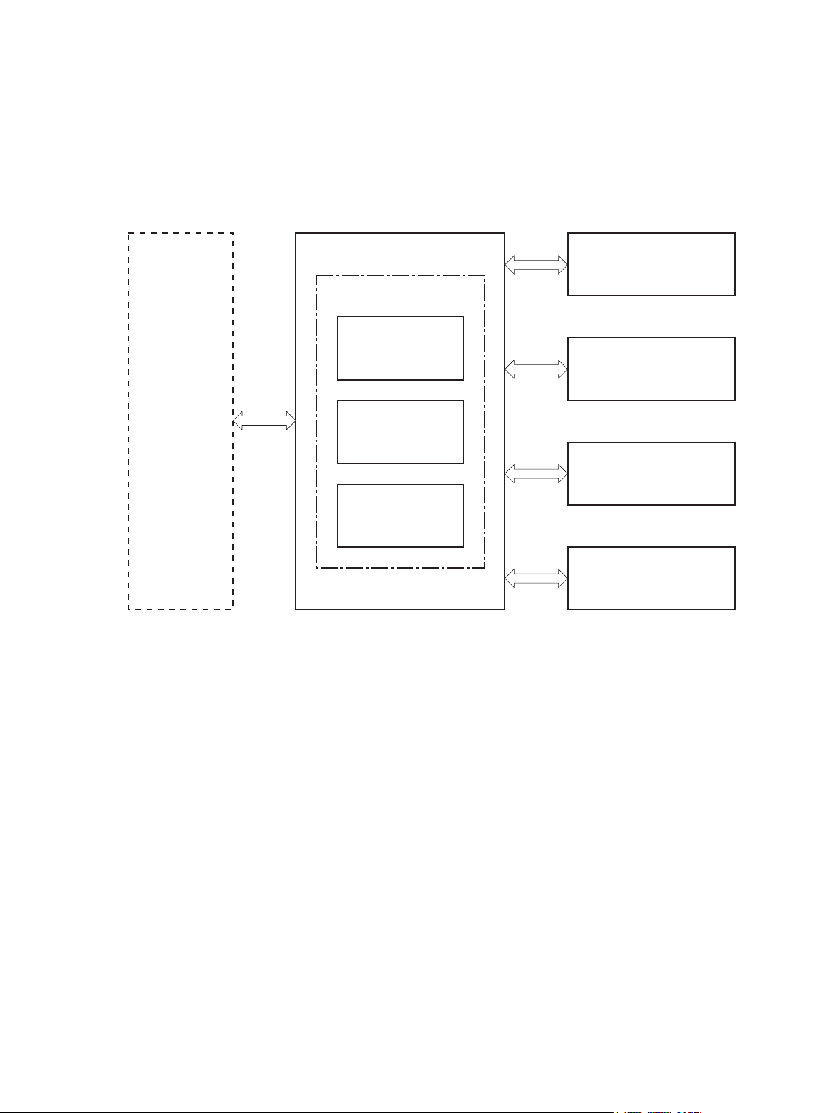
The product includes the following systems:
Engine control system
●
Laser scanner system
●
Image-formation system
●
Pickup and feed system
●
Accessory
●
Figure 1-1 Product systems
LASER SCANNER SYSTEM
ENGINE CONTROL
SYSTEM
IMAGE-FORMATION SYSTEM
PICKUP, FEED AND DELIVERY SYSTEM
ACCESSORY
2 Chapter 1 Theory of operation ENWW
Page 21
Product components
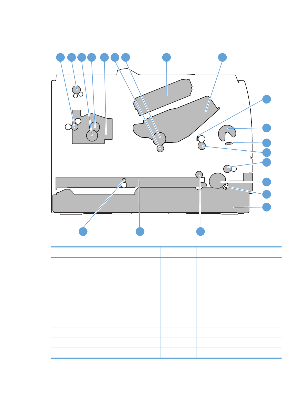
Figure 1-2 Product components
1
2 8 9
4 5 6 73
1010
11
12
13
13
14
15
16
17
181920
Table 1-1 Product components
Item Description Item Description
1 Fuser delivery roller 11 Multipurpose tray (Tray 1) pickup roller
2 Face-down delivery roller 12 Multipurpose tray (Tray 1) separation pad
3 Pressure roller 13 Registration roller
4 Fuser film assembly 14 Feed roller
5 Fuser 15 Tray 2 cassette pickup roller
6 Transfer roller 16 Tray 2 cassette separation pad
7 Photosensitive drum 17 Tray 2 cassette
8 Laser scanner 18 Duplex re-pickup roller (duplex models only)
9 Toner cartridge 19 Duplex feed assembly (duplex models only)
ENWW
10 Registration shutter 20 Duplex feed roller (duplex models only)
Basic operation
3
Page 22
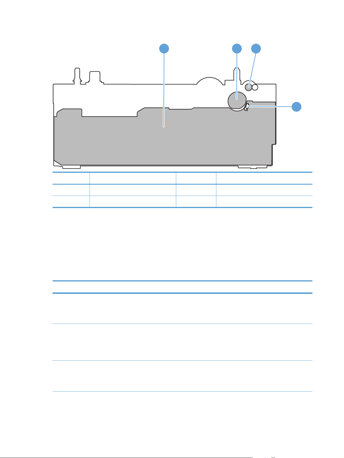
Figure 1-3 Optional Tray 3 components
1 2
Item Description Item Description
1 Tray 3 cassette 3 Tray 3 feed roller
2 Tray 3 pickup roller 4 Tray 3 separation pad
3
4
Sequence of operation
The product operational sequence is controlled by the DC controller that is on the engine control
system. The following table describes each period of a print operation from when the printer is turned
on until the motor stops rotating.
Table 1-2 Sequence of operation
Period Duration Purpose Remarks
WAIT From the time the power is
STBY (Standby period) From end of the WAIT or
INTR (Initial rotation) From the time the print
turned on or the door is
closed until the drum-phase
adjustment is complete
LSTR period until either the
print command is received
from the formatter or the
power is turned off
command is received until the
fuser temperature reaches its
target temperature
Brings the product to the
ready state
Maintains the product in
readiness for a print
command
Prepares the high-voltage
biases, laser scanner, and
fuser for printing
The product detects the toner
level, cartridge presence, and
environment.
The product enters sleep
mode when the formatter
sends a sleep command.
4 Chapter 1 Theory of operation ENWW
Page 23

Table 1-2 Sequence of operation (continued)
Period Duration Purpose Remarks
PRINT From the end of INTR period
until the fuser paper sensor
detects the trailing edge of
paper
LSTR (Last rotation) From the end of the PRINT
period until the delivery motor
stops rotating
Forms the images on the
photosensitive drum and
transfers the toner image to
the print media
Moves the printed sheet out
of the product, and stops the
output from the laser scanner
and high-voltage biases
The product enters the INTR
period as soon as the
formatter sends another print
command.
ENWW
Basic operation
5
Page 24
Engine control system
The engine control system coordinates all product functions and drives the other three systems.
The engine control system contains the DC controller, high-voltage power supply PCA, and low-voltage
power supply.
Figure 1-4 Engine control system components
Formatter
ENGINE CONTROL SYSTEM
LASER SCANNER SYSTEM
Engine controller
DC controller
IMAGE-FORMATION SYSTEM
Low-voltage
power supply
PICKUP, FEED AND
DELIVERY SYSTEM
High-voltage
power supply
ACCESSORY
6 Chapter 1 Theory of operation ENWW
Page 25
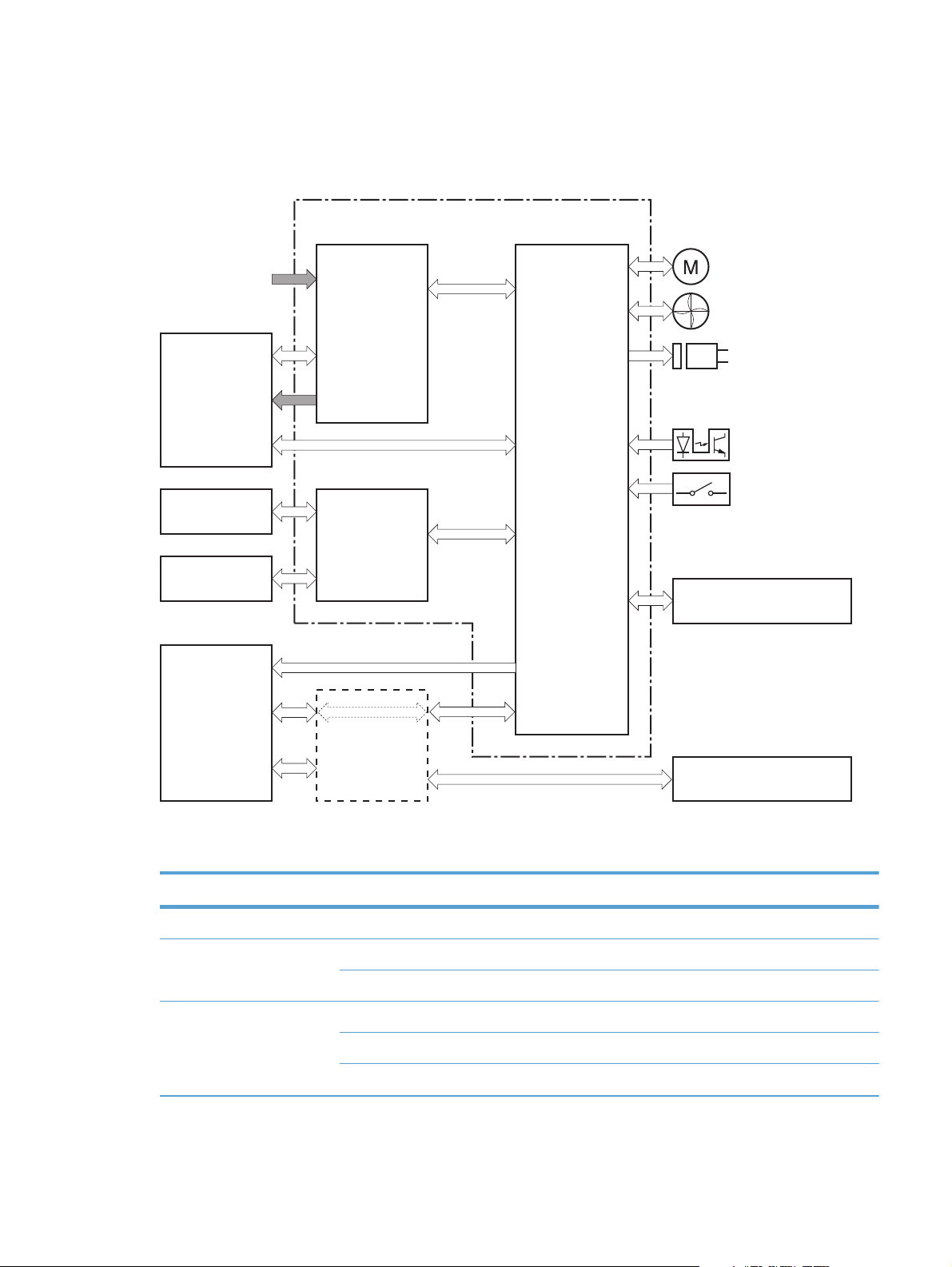
DC controller
The DC controller controls the product operational sequence.
Figure 1-5 DC controller
Engine controller
AC input
Fuser
Transfer roller
Cartridge
Laser scanner
assembly
Motor
Fan
Low-voltage
power supply
Solenoid
Photointerrupter
Switch
DC controller
High-voltage
power supply
Accessory
Formatter
ENWW
Table 1-3 DC controller electrical components
Component type Symbol Description
Fan FM1 Main fan
Motor M1 Main motor
M2 Scanner motor
Solenoid SL1 Multipurpose tray pickup solenoid
SL2 Cassette pickup solenoid
SL3 Duplex reverse solenoid (duplex models only)
Engine control system
Control panel
7
Page 26

Table 1-3 DC controller electrical components (continued)
Component type Symbol Description
Switch SW1001 Power switch
SW301 Door-open detection switch
Photointerrupter PS912 Top sensor
PS913 Paper width sensor
PS914 Cassette media out sensor
PS914 Left paper width sensor
PS915 Multipurpose tray media out sensor
PS915 Right paper width sensor
PS916 Fuser output sensor
PS916 Output-bin paper-full sensor
8 Chapter 1 Theory of operation ENWW
Page 27
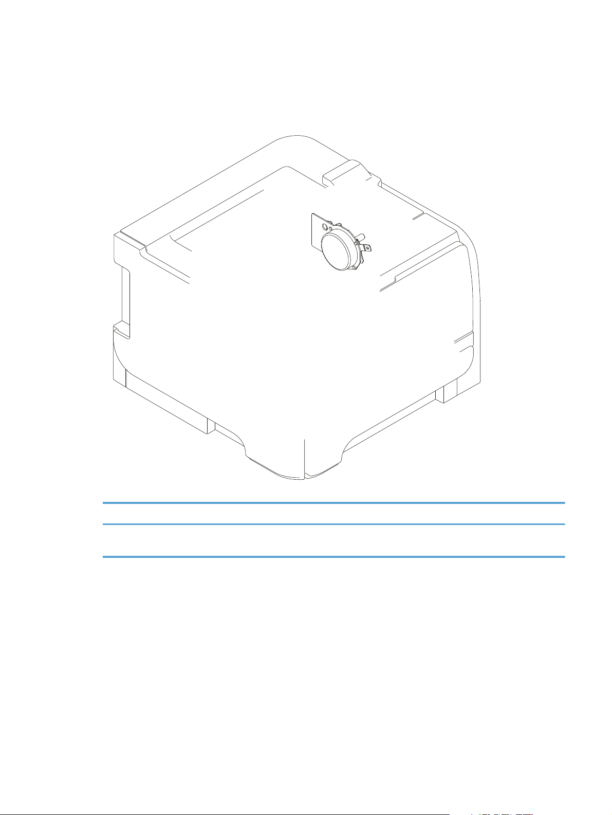
Motor control
The product has one motor for media feed and image formation.
Figure 1-6 Main motor
ENWW
Table 1-4 Motor control components
Symbol Name Driving part Failure detection
M1 Main motor Rollers in the product an
rollers in the paper feeder
Yes
Engine control system
9
Page 28
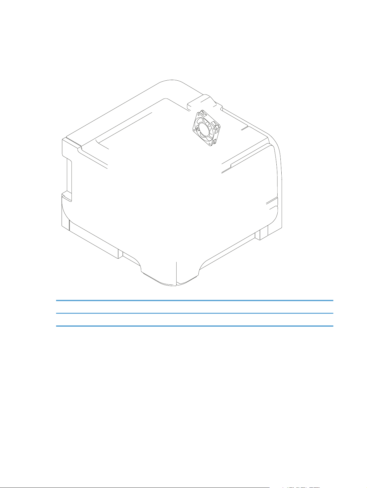
Fan control
The product has one fan for preventing the product from overheating.
Figure 1-7 Fan control
Table 1-5 Fan control components
Symbol Name Cooling area Type Speed
FM1 Fan Inside the product Intake Full
10 Chapter 1 Theory of operation ENWW
Page 29
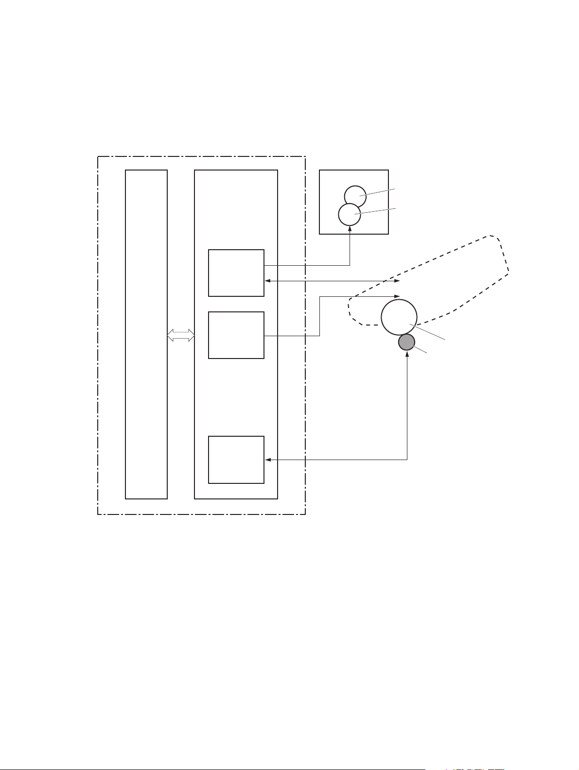
High-voltage power supply
The DC controller controls the high-voltage power supply to generate high-voltage biases. The highvoltage power supply generates the high-voltage biases that are applied to the primary charging roller,
developing roller, transfer roller, and fuser film.
Figure 1-8 High-voltage power supply
Engine controller
DC controller
High-voltage power supply
Fuser
Fuser film
Pressure roller
Primary
charging
bias circuit
Developing
bias circuit
Transfer
bias circuit
FB
PR
DV
TR
Cartridge
Primary charging roller
Developing roller
Photosensitive drum
Transfer roller
ENWW
Engine control system
11
Page 30
Fuser control circuit
The fuser control circuit controls the fuser temperature. The product uses an on-demand fusing method.
Figure 1-9 Fuser control circuit
H1
TP1
TH1
FUSER HEATER CONTROL signal
Fuser film
Pressure roller
FUSER TEMPERATURE signal
Fuser heater
safety circuit
DC controller
Fuser heater
control circuit
Fuser control circuit
Low-voltage power supply
Engine controller
Table 1-6 Fuser control circuit components
Symbol Name Description
H1 Fuser heater Heats the fuser film
TH1 Thermistor Detects fuser temperature (contact type)
TP1 Thermoswitch Prevents an abnormal temperature rise
of the fuser heater (contact type)
These temperature controls in the fuser are performed by the fuser heater control circuit and the fuser
heater safety. They are controlled by the DC controller.
12 Chapter 1 Theory of operation ENWW
Page 31

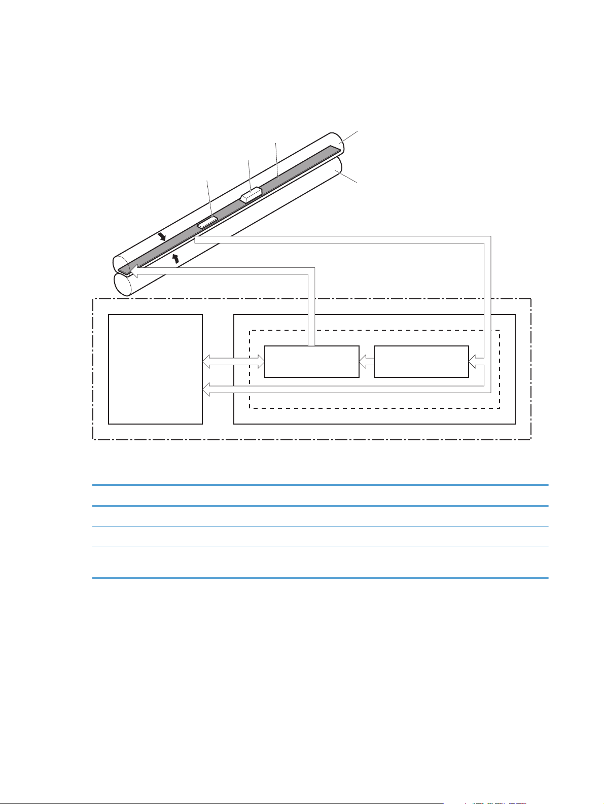
Fuser temperature control
The fuser temperature control maintains the fuser heater at its targeted temperature.
Figure 1-10 Fuser temperature control
Engine controller
Low-voltage power supply
Fuser control circuit
+24V
Relay control
circuit
Fuser heater
safety circuit
Fuser heater
control circuit
RL101
Frequency
detection circuit
DC controller
FREQSNS
FSRD
RLYD
FSRTH
Fuser film assembly
ENWW
TH1
Pressure roller
TP1
H1
H1: Fuser heater
TP1: Thermoswitch
TH1: Thermistor
Fuser
The DC controller monitors the fuser temperature (FSRTH) signal and sends the fuser heater control
(FSRD) signal according to the detected temperature. The fuser heater control circuit controls the fuser
heater depending on the signal so that the heater remains at the target temperature.
Engine control system
13
Page 32

Fuser protection function
When the protective function detects an abnormal temperature rise in the fuser, it interrupts the power
supply to the fuser heater. The following components prevent an abnormal temperature rise of the fuser
heater:
DC controller: The DC controller monitors the detected temperature of the thermistor. The DC
●
controller makes the fuser heater control signal inactive and releases the relay to interrupt power
supply to the fuser heater when it detects that the thermistor temperature is 240° C (464° F) or
higher.
Fuser heater safety circuit: The fuser heater safety circuit monitors the detected temperature of
●
the thermistor. The fuser heater safety circuit releases the relay control circuit to interrupt power
supply to the fuser heater when it detects that the thermistor temperature is 265° C (509° F) or
higher.
Thermoswitch: The contact of the thermoswitch is broken to interrupt power supply to the fuser
●
heater when it detects that the temperature fuse is 230° C (446° F) or higher
Fuser failure detection
The DC controller determines a fuser failure, makes the fuser heater control signal inactive, releases the
relay to interrupt power supply to the fuser heater, and notifies the formatter of a failure state when it
encounters the following conditions.
Start-up failure
●
If the detected temperature of the thermistor is kept at a specified temperature or higher for a
◦
specified period of heater start-up during the wait period.
If the detected temperature of the thermistor is kept at a specified temperature or lower for a
◦
specified period under the heater temperature control during the initial rotation period.
If the detected temperature of the thermistor is kept at a specified temperature or lower for a
◦
specified period under the heater temperature control during the print period.
If the detected temperature of the thermistor does not reach its targeted temperature within a
◦
specified period under the heater temperature control during the initial rotation period.
Abnormal low temperature
●
If the detected temperature of the thermistor is kept at a specified temperature or lower for a
◦
specified period under the heater temperature control.
14 Chapter 1 Theory of operation ENWW
Page 33

Abnormal high temperature
●
If the detected temperature of the main thermistor is kept at a specified temperature or higher
◦
for a specified period.
Drive circuit failure
●
If a specified frequency of the frequency signal is not detected within a specified period after
◦
the product is turned on.
If an out of specified frequency of the frequency signal is detected after the product is turned
◦
on.
ENWW
Engine control system
15
Page 34

Low-voltage power supply
The low-voltage power supply converts AC power from the power receptacle into DC power to cover
the DC loads.
Figure 1-11 Low-voltage power supply
Low-voltage power supply
Engine controller
Noise
filter
Protection
circuit
Fuse
(FU101)
Fuse
(FU102)
+24V generation
circuit
Noise
filter
+3.3V generation
circuit
Fusing
control circuit
PSAVE
+3.3V
+24V
High-voltage power supply
DOORSNS
DC controller
FET
+24U
Door switch
PSW
Power switch
(SW1001)
Fuser
+24P1
(SW301)
Protective function
The low-voltage power supply has a protective function against overcurrent and overvoltage conditions
to prevent failures in the power supply circuit. If an overcurrent or overvoltage event occurs, the system
automatically cuts off the output voltage.
If the DC power is not being supplied from the low-voltage power supply, the protective function might
have activated. In this case, turn off the power switch, and then unplug the power cord. Do not plug in
the power cord or turn the power switch on again until the root cause is found.
16 Chapter 1 Theory of operation ENWW
Page 35

In addition, two fuses in the low-voltage power supply protect against an overcurrent event. If an
overcurrent event occurs in the AC line, the fuse blows and cuts off the power distribution.
Safety
For safety purposes, the product has a function to interrupt the 24V power supply to the fuser and the
high-voltage power supply. The door switch is turned off and 24V power stops if the cartridge door is
opened (SW301 is turned off).
The product has the power switch on the DC line, so if the AC power flows, even the power switch is
turned off. Be sure to unplug the power cord before disassembling the product.
Low-voltage power supply unit failure detection
The DC controller determines a low-voltage power supply failure, stops 24V output and notifies the
formatter when it detects that the 24V output is higher than the specified voltage.
ENWW
Engine control system
17
Page 36

Laser scanner system
The laser scanner system forms a latent image on the photosensitive drum according to the video
signals sent from the formatter.
The main components of the laser scanner are the laser assembly and the scanner motor assembly,
which are controlled by the signals sent from the DC controller.
Figure 1-12 Laser scanner system
Engine controller
DC controller
Formatter
VIDEO signal
BD INPUT signal
LASER CONTROL signal
SCANNER MOTOR SPEED CONTROL signal
Scanner mirror
BD sensor
Scanner motor assembly
Photosensitive drum
Laser assembly
18 Chapter 1 Theory of operation ENWW
Page 37

Laser failure detection
The optical unit failure detection sensor manages the laser scanner unit failure-detection functions. The
DC controller identifies the laser scanner unit failure and notifies the formatter if the laser scanner unit
encounters the following conditions:
Scanner motor failure
●
BD sensor failure
●
ENWW
Laser scanner system
19
Page 38

Image-formation system
The image-formation system forms a toner image on the paper. The image-formation system includes the
following components:
Toner cartridge
●
Transfer roller
●
Fuser
●
Laser scanner
●
The DC controller controls the laser scanner and high-voltage power supply to form the toner image on
the photosensitive drum. The image is transferred to the paper and fused.
Figure 1-13 Image-formation system
Laser scanner
Laser beam
Fuser
Fuser film
Pressure roller
Cartridge
Photosensitive drum
Transfer roller
Engine controller
High-voltage power supply
DC controller
20 Chapter 1 Theory of operation ENWW
Page 39

Image-formation process
Laser printing requires the interaction of several different technologies including electronics, optics, and
electrographics to provide a printed page. Each process functions independently and must be
coordinated with the other processes. Image formation consists of the following processes:
Latent-image formation
●
Development
●
Transfer
●
Fuser
●
Drum cleaning
●
These processes are divided into seven steps, which are shown below and described in the following
sections.
Figure 1-14 Image-formation process
Paper path
Direction of the drum rotation
Block
Step
Latent image formation
2. Laser-beam exposure
Drum cleaning
Delivery
6. Fusing
Fusing
Latent-image formation stage
During the steps that comprise this stage, a latent image is formed by applying a negative charge to
the photosensitive drum. You cannot see this image on the drum.
1. Primary charging
7. Drum cleaning
5. Separation
Transfer
3. Developing
4. Transfer
Developing
Pickup
ENWW
Image-formation system
21
Page 40

Step 1: Primary charging
To prepare for latent image formation, the surface of the photosensitive drum is charged with a uniform
negative charge. The primary charging roller receives the primary charging bias, and then the roller
charges the drum directly.
Figure 1-15 Primary charging process
Primary charging roller
Photosensitive drum
Step 2: Laser-beam exposure
Primary charging bias
The laser beam scans the photosensitive drum to neutralize the negative charge on portions of the drum
surface. An electrostatic latent image forms where the negative charge was neutralized.
Figure 1-16 Laser-beam exposure
Unexposed area Exposed area
Developing stage
The developing roller contacts the photosensitive drum and deposits toner on the electrostatic latent
image, which becomes visible.
Laser beam
Step 3: Development
Toner acquires a negative charge as a result of the friction from the developing roller rotating against
the developing blade. When the negatively charged toner comes in contact with the drum, it adheres to
22 Chapter 1 Theory of operation ENWW
Page 41

the electrostatic latent image. When the toner is on the drum, the image becomes visible. The
developing bias is applied to the developing roller.
Figure 1-17 Development process
Blade
Developing roller
Exposed area
Unexposed area
Photosensitive drum
Unexposed area
Exposed area
Developing bias
ENWW
Image-formation system
23
Page 42

Transfer stage
During the transfer stage, the photosensitive drum transfers a toner image to the paper.
Step 4: Transfer
The transfer bias is applied to the transfer roller to give the paper a positive charge. The positively
charged paper attracts the negatively charged toner from the photosensitive drum surface.
Figure 1-18 Transfer process
Transfer roller
Photosensitive
drum
Paper
Transfer bias
Step 5: Separation
The elasticity of the paper and the curvature of the photosensitive drum cause the paper to separate
from the drum surface. The static charge eliminator reduces back side static discharge of the paper for
stable paper feeding and image quality.
Figure 1-19 Separation from the drum
Static charge eliminator
Photosensitive
drum
Paper
Transfer roller
24 Chapter 1 Theory of operation ENWW
Page 43

Fusing stage
Until the fusing stage is complete, the image is not permanently affixed to the print media. The toner
can be easily smudged until the heat and pressure of the fusing process fix the image to the sheet.
Step 6: Fusing
The product uses an on-demand fusing method to fuse the toner image onto the media. The toner image
is permanently affixed to the print media by the heat and pressure. The fusing bias is applied to the
pressure roller to improve image quality.
Figure 1-20 Fusing
Fuser heater
Fusing bias
Fuser film
Toner
Paper
Pressure roller
ENWW
Image-formation system
25
Page 44

Drum cleaning stage
Not all of the toner is removed from the photosensitive drum during the transfer stage. During the
cleaning stage, the residual, or waste, toner is cleared from the drum surface to prepare the surface for
the next latent-image formation.
Step 7: Drum cleaning
The cleaning blade scrapes the residual toner off the surface of the photosensitive drum and deposits it
in the toner collection box. The drum is now clear and ready for the next image-formation process.
Figure 1-21 Drum cleaning
Cleaning blade
Toner collection box
Photosensitive
drum
26 Chapter 1 Theory of operation ENWW
Page 45

Pickup and feed system
The system picks up and feeds the print media. It consists of several types of feed rollers. The duplex
feed assembly in the duplex models reverses and re-sends the paper to print on second side of paper.
Figure 1-22 Pickup and feed system paper path
Face-down delivery roller
Pressure roller
Fuser delivery roller
: Simplex media path
: Duplex media path
Fuser film
Duplex feed roller
Photosensitive drum
Transfer roller
Duplex re-pickup roller
Cassette pickup roller
Registration roller
MP tray pickup roller
The pickup and feed system includes the following electrical components.
MP tray separation pad
Cassette separation pad
ENWW
Pickup and feed system
27
Page 46

Figure 1-23 Pickup and feed system electrical components
SL3
PS918
M1
SL1
PS915
PS916
PS913
PS914
PS915
PS912
PS914
SL2
Table 1-7 Pickup and feed system electrical components
Number Description Signal
M1 Main motor Main motor control signal
SL1 Cassette pickup solenoid Cassette pickup solenoid control signal
SL2 Multipurpose tray pickup solenoid MP tray pickup solenoid control signal
SL3 Duplex reverse solenoid (duplex models
only)
PS912 Top-of-page sensor Top signal
Duplex reverse solenoid control signal
PS913 Paper width sensor Media width signal
PS914 Cassette paper out sensor Cassette media out signal
PS914 Left paper width sensor Media width signal
PS915 Multipurpose tray media out sensor MP tray media out signal
PS915 Right paper width sensor Media width signal
PS916 Fuser output sensor Fuser output signal
PS918 Output-bin full sensor Output-bin media-full signal
28 Chapter 1 Theory of operation ENWW
Page 47

Jam detection
The product uses the following sensors to detect the presence of paper and to check whether the paper
is being fed correctly or has jammed.
Figure 1-24 Jam detection sensors
PS916
PS913
PS914
PS915
PS912
ENWW
: Simplex media path
: Duplex media path
Number Description
PS912 Top-of-page sensor
PS913 Paper-width sensor
PS914 Left paper-width sensor
Pickup and feed system
29
Page 48

Number Description
PS915 Right paper-width sensor
PS916 Fuser output sensor
The product detects the following jams:
Pickup delay jam
●
Pickup stationary jam
●
Delivery delay jam
●
Delivery stationary jam
●
Fuser wrapping jam
●
Door open jam
●
Residual paper jam
●
Duplex reverse jam 1 (duplex models only)
●
Duplex reverse jam 2 (duplex models only)
●
30 Chapter 1 Theory of operation ENWW
Page 49

Paper feeder (optional Tray 3)
The paper feeder is optionally installed at bottom of the product. It picks up and feeds the paper to the
product. The product DC controller controls the paper feeder operational sequence.
Figure 1-25 Paper-feeder paper path
ENWW
: Simplex media path
: Duplex media path
PF feed roller
The next figure shows the paper feeder controller signal flow.
PF separation pad
PF pickup roller
Paper feeder (optional Tray 3)
31
Page 50

Figure 1-26 Paper feeder signal flow
Paper feeder
Solenoid
DC controller
+24V
Paper feeder
connector PCA
Photointerrupter
Table 1-8 Paper feeder components
Name Symbol Description
Solenoid SL4 Paper-feed pickup solenoid
Photointerrupter PS1201 Paper-feeder-cassette paper-out sensor
32 Chapter 1 Theory of operation ENWW
Page 51

Paper feeder operation
The paper feeder picks up the paper from the cassette and feeds it to the product.
Figure 1-27 Paper feeder electrical components
M1
SL4
PS1201
Number Description Signal
SL4 Tray 3 cassette pickup solenoid Tray 3 cassette pickup solenoid control signal
PS1201 Tray 3 cassette paper presence sensor Tray 3 cassette paper presence signal
ENWW
Paper feeder (optional Tray 3)
33
Page 52

Jam detection
The product uses the following sensors to detect the presence of paper and to check whether the paper
is being fed correctly or has jammed.
Figure 1-28 Jam detection sensors
PS916
PS913
PS914
PS915
PS912
: Simplex media path
: Duplex media path
Number Description
PS912 Top-of-page sensor
PS913 Paper-width sensor
PS914 Left paper-width sensor
34 Chapter 1 Theory of operation ENWW
Page 53

Number Description
PS915 Right paper-width sensor
PS916 Fuser output sensor
Paper jam events in the paper feeder are detected by the DC controller. The product detects the
following jams:
Pickup delay jam
●
Pickup stationary jam
●
Delivery delay jam
●
Delivery stationary jam
●
Fuser wrapping jam
●
Door open jam
●
Residual paper jam
●
Duplex reverse jam 1 (duplex models only)
●
Duplex reverse jam 2 (duplex models only)
●
ENWW
Paper feeder (optional Tray 3)
35
Page 54

USB flash drive
The HP LaserJet Pro 400 M401dn Printer and the HP LaserJet Pro 400 M401dw Printer models feature
printing from a USB flash drive. These models print the following file types from the USB flash drive.
PDF
●
RGB JPEG
●
When a USB flash drive is inserted into the front of the product, the control panel will display the USB
Flash Drive menu. The files on the USB flash drive can be accessed from the control panel using the
touchscreen. Any RGB JPEG or PDF files on the USB flash drive can be printed directly from the product
control panel.
36 Chapter 1 Theory of operation ENWW
Page 55

2 Solve problems
Solve problems checklist
●
Menu map
●
Troubleshooting process
●
Tools for troubleshooting
●
Clear jams
●
Solve paper-handling problems
●
Solve image quality problems
●
Clean the product
●
Solve performance problems
●
Solve connectivity problems
●
Service mode functions
●
Manually update the firmware
●
ENWW 37
Page 56

Solve problems checklist
1. Make sure that the product is set up correctly.
a. Press the power button to turn on the product or to deactivate the Auto-Off mode.
b. Check the power-cable connections.
c. Make sure that the line voltage is correct for the product power configuration. (See the label
that is on the back of the product for voltage requirements.) If you are using a power strip
and its voltage is not within specifications, plug the product directly into the wall. If it is
already plugged into the wall, try a different outlet.
2. Check the cabling.
a. Check the cable connection between the product and the computer. Make sure that the
connection is secure.
b. Make sure that the cable itself is not faulty by using a different cable, if possible.
c. Check the network connection (network models only): Make sure the network light is lit. The
network light is next to the network port on the back of the product.
If the product remains unable to connect to the network, uninstall and then reinstall the
product. If the error persists, contact a network administrator.
3. Check to see if any messages appear on the control panel.
4. Make sure that the paper that you are using meets specifications.
5. Make sure that the paper is loaded correctly in the input tray.
6. Make sure that the product software is installed correctly.
7. Verify that you have installed the printer driver for this product, and that you are selecting this
product from the list of available printers.
8. Print a configuration page.
a. If the page does not print, verify that the input tray contains paper and that the paper is
properly loaded.
b. Make sure that the toner cartridge is installed correctly.
38 Chapter 2 Solve problems ENWW
Page 57

c. If the page jams in the product, clear the jam.
d. If the print quality is unacceptable, complete the following steps:
Verify that the print settings are correct for the paper that you are using.
●
Solve print-quality problems.
●
9. Print a small document from a different program that has worked in the past. If this solution works,
then the problem is with the program you are using. If this solution does not work (the document
does not print), complete these steps:
a. Try printing the job from another computer that has the product software installed.
b. Check the cable connection. Direct the product to the correct port, or reinstall the software,
selecting the connection type that you are using.
ENWW
Solve problems checklist
39
Page 58

Menu map
Use the Reports menu to print a menu map of the control panel-menu layout. The active settings for
each menu are listed.
Print the menu map (LCD control panel)
1. At the product control panel, press the OK button to open the menus.
2. Select the Reports menu, and then press the OK button.
3. Select the Menu Structure item, and then press the OK button to print the report.
Print the menu map (touchscreen control panel)
1.
From the Home screen on the product control panel, touch the Setup
2. Touch the Reports menu.
3. Touch the Menu Structure item to print the report.
button.
40 Chapter 2 Solve problems ENWW
Page 59

Troubleshooting process
When the product malfunctions or encounters an unexpected situation, the product control panel alerts
you to the situation. This chapter contains information to help diagnose and solve problems.
Use the pre-troubleshooting checklist to evaluate the source of the problem and to reduce the
●
number of steps that are required to fix the problem.
Use the troubleshooting flowchart to pinpoint the root cause of hardware malfunctions. The
●
flowchart guides you to the section of this chapter that contains steps for correcting the
malfunction.
Before beginning any troubleshooting procedure, check the following issues:
Are supply items within their rated life?
●
Does the configuration page reveal any configuration errors?
●
NOTE: The customer is responsible for checking supplies and for using supplies that are in good
condition.
Pre-troubleshooting checklist
The following table includes basic questions to ask the customer to quickly help define the problem(s).
General topic Questions
Environment
Media
Input trays
Is the product installed on a solid, level surface (+/- 1°)?
●
Is the power-supply voltage within ± 10 volts of the specified power source?
●
Is the power-supply plug inserted in the product and the outlet?
●
Is the operating environment within the specified parameters?
●
Is the product exposed to ammonia gas, such as that produced by diazo
●
copiers or office cleaning materials?
NOTE: Diazo copiers produce ammonia gas as part of the copying
processes. Ammonia gas (from cleaning supplies or a diazo copier) can have
an adverse effect on some product components (for example, the toner
cartridge OPC).
Is the product exposed to direct sunlight?
●
Does the customer use only supported media?
●
Is the media in good condition (no curls, folds, or distortion)?
●
Is the media stored correctly and within environmental limits?
●
Is the amount of media in the tray within specifications?
●
Is the media correctly placed in the tray?
●
ENWW
Are the paper guides aligned with the stack?
●
Is the tray correctly installed in the product?
●
Troubleshooting process
41
Page 60

General topic Questions
Toner cartridge
Transfer unit and fuser
Covers
Condensation
Miscellaneous
Is the toner cartridge installed correctly?
●
Are the transfer unit and fuser installed correctly?
●
Is the front cover closed?
●
Does condensation occur following a temperature change (particularly in
●
winter following cold storage)? If so, wipe affected parts dry or leave the
product on for 10 to 20 minutes.
Was a toner cartridge opened soon after being moved from a cold to a warm
●
room? If so, allow the toner cartridge to sit at room temperature for 1 to 2
hours.
Check for and remove any non-HP components (toner cartridges, memory
●
modules, and EIO cards) from the product.
If the hardware or software configuration has not changed or the problem is
●
not associated with any specific software, see the complete service manual for
this product.
Remove the product from the network and ensure that the failure is associated
●
with the product before beginning troubleshooting.
For any print-quality issues, calibrate the product.
●
42 Chapter 2 Solve problems ENWW
Page 61

Determine the problem source
The following table includes basic questions to ask the customer to quickly help define the problem or
problems.
General topic Questions
Environment
Paper
Input tray
Is the product installed on a solid, level surface (± 1°)?
●
Is the power-supply voltage within ± 10 volts of the specified power source?
●
Is the power-supply plug inserted in the product and the outlet?
●
Is the operating environment within the specified parameters?
●
Is the product exposed to ammonia gas, such as that produced by diazo
●
copiers or office cleaning materials?
NOTE: Diazo copiers produce ammonia gas as part of the coping
processes. Ammonia gas (from cleaning supplies or a diazo copier) can have
an adverse affect on some product components (for example, the toner
cartridge imaging drum).
Is the product exposed to direct sunlight?
●
Does the customer use only supported paper?
●
Is the paper in good condition (no curls, folds, or distortion)?
●
Is the paper stored correctly and within environmental limits?
●
Is the amount of paper in the tray within specifications?
●
Is the paper correctly placed in the tray?
●
Are the paper guides aligned with the stack?
●
Supplies
Transfer roller and fuser
Covers
Condensation
Miscellaneous
Is the toner cartridge installed correctly and firmly seated?
●
Has the sealing tape been removed from the toner cartridge?
●
Is the toner cartridge within its estimated life? (Check the supplies status page.)
●
Are the transfer roller and fuser installed correctly?
●
Are the front and rear doors firmly closed?
●
Does condensation occur following a temperature change (particularly in
●
winter following cold storage)? If so, wipe affected parts dry or leave the
product on for 90 to 120 minutes.
Was a toner cartridge opened soon after being moved from a cold to a warm
●
room? If so, allow the toner cartridge to sit at room temperature for 1 to 2
hours.
Check for and remove any non-HP components (for example, a toner
●
cartridge) from the product.
Remove the product from the network and make sure that the failure is with the
●
product before beginning troubleshooting.
ENWW
Troubleshooting process
43
Page 62

Power subsystem
Power-on checks
When you turn on the product, if it does not make any sound or if the control-panel display is blank,
check the following items:
Verify that the product is plugged directly into an active electrical outlet that has the correct
●
voltage. Do not plug the product into a surge protector or power strip.
Verify that the on/off switch is in the on position.
●
Verify that the formatter is seated and operating correctly.
●
Remove any HP Jetdirect accessories or other devices, and then try to turn the product on again.
●
Make sure that the control-panel display is connected.
●
Check the two fuses on the power supply.
●
If necessary, replace the power supply.
●
If necessary, replace the DC controller.
●
Control-panel checks
Use the product control panel to conduct tests on the control panel LEDs, display, or buttons.
LCD control panel checks
1. On the product control panel, press the OK button to open the menus.
2. Press the left arrow button, and then quickly press the Cancel
to Ready status.
3. Press the OK button again to open the menus. The first menu should be the 2ndary Service
menu.
4. Press the OK button again to open the 2ndary Service menu, and then navigate to one of the
following menu items.
LED Test
●
Display Test
●
Button Test
●
5. Press the OK button to begin the selected test.
6. After the test has finished, return the product to the Ready state, and then press the Cancel
button to remove the 2ndary Service menu from the menu list.
button. The display should return
44 Chapter 2 Solve problems ENWW
Page 63

Touchscreen control panel checks
1.
From the Home screen on the product control panel, touch the Setup
2. Touch the left arrow button, and then quickly touch the Cancel
to Ready status.
3.
Press the Setup
Service menu.
4. Touch the 2ndary Service menu, and then scroll to one of the following menu items.
LED Test
●
Display Test
●
Button Test
●
5. Touch the menu item to begin the test.
6. After the test has finished, return the product to the Ready state, and then touch the Cancel
button to remove the 2ndary Service menu from the menu list.
button again to open the menus. The first menu should be the 2ndary
button.
button. The display should return
ENWW
Troubleshooting process
45
Page 64

Tools for troubleshooting
Component diagnostics
LED diagnostics
Network LEDs (network models only)
The onboard network solution has two network port LEDs. When the product is connected to a properly
working network through a network cable, the yellow LED indicates network activity, and the green LED
indicates the link status. A blinking yellow LED indicates network traffic. If the green LED is off, a link
has failed.
For link failures, check all of the network cable connections. In addition, you can try to manually
configure the network card link speed setting by using the product control-panel.
Change the Link Speed setting on an LCD control panel
1. At the product control panel, press the OK button to open the menus.
2. Select the Network Setup menu, and then press the OK button.
3. Select the Link Speed item, and then press the OK button.
4. Select the appropriate link speed, and then press the OK button.
Change the Link Speed setting on a touchscreen control panel
1.
From the Home screen on the product control panel, touch the Setup
2. Scroll to, and then touch the Network Setup menu.
3. Scroll to, and then touch Link Speed item.
4. Touch the appropriate link speed.
Control panel LEDs
The state of the Ready light and Attention light on the product signal the product status. The following
table outlines the possible control-panel light states.
Product state Ready light state Attention light state
Initializing Blinking Blinking
Ready On Off
Receiving data/processing job or
cancelling job
Blinking Off
button.
Error message Off Blinking
46 Chapter 2 Solve problems ENWW
Page 65

Product state Ready light state Attention light state
Fatal error (49 or 79 error)
1
The product will power off and then power on after one of these errors occurs.
Engine diagnostics
Engine test
If the duplex unit is disabled, the engine test produces a single-sided sheet with horizontal lines when
you perform the engine test. If the duplex unit is activated (the default state), the engine test produces a
double-sided sheet with horizontal lines when you perform the engine test.
To perform the test, with the product in the Ready state, open and shut the cartridge door three times. If
the engine is functioning properly, the product will initialize and then print the test page
Diagrams
Plug/jack locations
1
On On
ENWW
Table 2-1 Plug/jack locations
Item Description
1 Hi-Speed USB 2.0 port
2 Network port
Tools for troubleshooting
47
Page 66

Locations of major components
Figure 2-1 Major components (1 of 2)
1 2 3 4
Table 2-2 Major components (1 of 2)
Item Description
1 Registration assembly
2 Fuser assembly
3 Feed drive assembly (simplex models)
Duplex drive assembly (duplex models)
4 Laser scanner assembly
5 Duplex feed assembly
5
48 Chapter 2 Solve problems ENWW
Page 67

Figure 2-2 Major components (2 of 2)
1 2
43
Table 2-3 Major components (2 of 2)
Item Description
1Fan
2 Transfer roller
3 Main motor
4 Sensor assembly
ENWW
Tools for troubleshooting
49
Page 68

General timing chart
12
Fuser heater
12
Fuser heater
The following charts lists the approximate timing for this product, specified in seconds.
Figure 2-3 Timing diagram
STBYRTSLTNIRPRTNIYBTSTIAW
Power ON
Signal
1 TOP sensor (PS912)
4 Scanner motor
2 Fuser output sensor (PS916)
3 Print command (EEC12)
Laser6BD signal (BDO)
5
Primary charging bias (DC)
Primary charging bias (AC)
7 Main motor (M1)
9
8
Transfer bias
10 Developing bias
11
Main fan (FM1)
Cassette pickup solenoid (SL2)
14
13
50 Chapter 2 Solve problems ENWW
Page 69

General circuit diagrams
Figure 2-4 Circuit diagram — LCD control panel models
Connector PCA
123456
1234567
TAG
COILB
COILA
1234567
+24P1
FANLOCK
+24P1
+24P1
/DUPSOL
+24P1
/CSTSOL
J1205
J1103
4
GND
/DEC
213
/ACC
1234
1234
4213
J802
J1105
FM1
123 2
123
GND
321
J6
J1101
12
12
12
SL
12
SL
1234567
12
1234567
134567
FANLOCK
2
DUPSOL
CSTSOL
GND
/DEC
/ACC
+24P1
J207
J581
12
TAG1
TAG2
S MODE
21
/SO(OPT SNS)
3456
/SI(OPT SOL)
/TESTP
GND
+3.3U
7
+24P1
J211
FB
J302
J7
1234567
J201
1
2
/BDO
WAKEVC
AC-N
J1104
1
12
7
J1102
COR1
J2100
12
FT3
A
1234
M2
M
SL
2
1
12
21
+24V
MPSOL
Formatter
3456789
GND
WAKEENG
/SCLK
/SC
/RSTO
AC-H
J101
3
21
23
1
COR2
INL101
321
12
1234567891011 13
GND(DCOM)
CNT2
CNT0
CNT1
8910
12
14
111315
1011121314
GND
CNT2
ILMLEDCLK
GND
CNT1
PSW1
15
CNT0
MPSOL
+24P2
/ILMLED
+3.3V
J215
12345
12345
/BDI
+3.3U
J1001
1234
5
12345
SW1001
2
1
LED1001
2
1
B
scanner
assembly
Laser
GND(DCOM)
/VDO2
VDO2
GND(DCOM)
VDO1
/VDO1
456
J9
J216
345612
23456
1
GND
GND
+3.3C
Engine controller PCA
12
+3.3V
GND(PB)
3
345612
GND
+3.3C
1234567891011 13
/BDI
12
+24P2
J202
J1202
J801
J5
SW301
21
FT2
J2142
+24P1
MFG
5
12345
23
154
M1
/CPRESET
FT1
+24U
1
/MDEC
M
C
/CPINT
CPCLK
+3.3V
CPOUT
1
J2141
/MACC
2345
+5V
CPIN
GND
+24V
FULSNS
WDSNS1
/PISNS
WDSNS2
WDSNS3
/CSTSNS
/MPSNS
/POSNS
GND
1
1234
54321
+3.3U
+3.3U
+3.3U
+3.3U
+3.3U
FSRTH
12
SW7521SW7421SW7321SW7221SW7121SW70
LED221LED1
LED3
10
8
9
J1
J2
123456789
STB1
/LED3
+5V
8
7
6
5
4
3
2
1
J4
1234567
654 3 2 1
10
+3.3V
STB3
STB2
KIN1
KIN0
/LED2
/LED1
Control panel
21
12
1
2
3
4
5
6
7
8
J1
J213
1
J918
PS918
123
123
GND
J203
1234
123456
56
GND
J204
21
GND
3
321
23 123 123
1
62534
J912
J914
PS912
PS913
PS914
PS915
PS914
321
321
321
321
321
321
J205
123
GND
J206
123
GND
321123
123
J915
PS915
321
Fuser assembly
J916
PS916
321
J210
TH1
12
GND
21
12
J102
TSH1
21
12
ACH
ACN
TP
12
TP1
21
J4
H1
21
D
ENWW
Tools for troubleshooting
51
Page 70

Figure 2-5 Circuit diagram — touchscreen control panel models (1 of 2)
Connector PCA
FANLOCK
/DUPSOL
/CSTSOL
1234567
123456
TAG
COILB
COILA
1234567
J1205
+24P1
+24P1
+24P1
+24P1
J1103
4
GND
/DEC
213
/ACC
1234
J1105
123
123
GND
321
1234
1234
M2
M
4213
J802
SL
2
FM1
1
J6
2
21
MPSOL
1
+24V
12345
CNT0
assembly
scanner
Laser
J801
12
6
4
8910
11
13
6
VDO1
/VDO1
GND(DCOM)
CNT2
CNT1
7
789
VDO2
GND(DCOM)
/VDO2
5
10
3
11
12
GND(DCOM)
GND(PB)
2
1
13
J5
+3.3V
/BDI
654 3 2 1
J1101
12
12
12
SL
J1104
12
12
1
SL
2
J1102
7
1 34567
FANLOCK
2
DUPSOL
CSTSOL
GND
/DEC
/ACC
COR1
J2100
12
+24P1
J207
J581
12
12
TAG1
TAG2
J7
234
1
J201
1
2
/BDO
WAKEVC
3456789
WAKEENG
/SCLK
Formatter
5678910111315
/SC
/RSTO
1214
1011121314
GND
/BDI
+3.3U
GND
CNT2
CNT1
CNT0
15
MPSOL
+24P2
Engine controller PCA
456
561
34561
2
123456
GND
GND
+3.3C
23
1
34
2
J9
SW301
21
FT1
FT2
+24V
+24U
1
1
J216
J2141
J2142
GND
+24P2
+3.3C
+3.3U
FULSNS
WDSNS1
/PISNS
WDSNS2
+3.3U
WDSNS3
+3.3U
/CSTSNS
J213
1
J918
PS918
123
123
GND
J203
1234
123456
56
GND
J204
21
GND
321
3
23 123 123
321
PS912
321
1
PS913
321
PS914
62534
321
J912
PS915
321
J914
PS914
321
J205
12345671234567
S MODE
21
3456
/TESTP
GND
+3.3U
7
+24P1
J211
+3.3U
/MPSNS
+3.3U
/POSNS
123
GND
J206
123
GND
321123 12
123
J915
J916
PS915
321
Fuser assembly
PS916
321
J210
GND
FSRTH
ILMLEDCLK
/ILMLED
5
12345
1234
SW1001
1
LED1001
B
GND
4
45
+3.3V
PSW1
3
3
2
21
J215
12
12
J1001
5
AC-N
FB
J302
AC-H
2
J101
321
31
COR2
FT3
INL101
321
A
J202
J1202
M1
/MDEC
+24P1
MFG
345
12345
23
154
M
C
/MACC
GND
12345
12
54321
ACH
ACN
TH1
21
12
J102
TSH1
21
12
TP
12
TP1
21
J4
H1
21
D
52 Chapter 2 Solve problems ENWW
Page 71

Figure 2-6 Circuit diagram — touchscreen control panel models (2 of 2)
Wireless
J17
Formatter
USB PCA
561234
561234
561234
561234
24 262018
22
21 23 25
16
19
8910
12
14
11 13 15 17
654 3 2 1
J2
1234567
J71
1234567891011 13 15 17 19 21 23 25
SDI
+3.3V
GND7
SDO
SCLK
Control panel
2
4
6
8
10
12
14
16
18
20
22
24
26
A
Relay
1
3
5
7
9
11
13
15
17
19
21
23
25
B
26
SDI
25
+3.3V
24
GND7
23
SDO
22
SCLK
21
/IRQ
20
/RESET
19
+5V
18
+24V
17
D7
16
D6
15
GND6
14
D5
13
D4
12
GND5
11
D3
10
D2
9
GND4
8
D1
7
D0
6
GND3
5
HSYNC
4
VSYNC
3
GND2
2
DCLK
1
GND1
J72J20
/RESET
/IRQ
+5V
+24VD7D6
C
12 14 22
GND6D5D4
GND5D3D2
GND4D1D0
24 26201816
GND3
HSYNC
VSYNC
GND2
DCLK
Engine controller assembly
GND1
D
ENWW
Tools for troubleshooting
53
Page 72

Figure 2-7 Circuit diagram — optional Tray 3
654 3 2 1
PF connector PCA
OPT SOL
OPT SNS
+3.3U
+24P1
GND
3
1
27
1234567
J1201
OPT SOL
+24P1
+3.3U
J1202
12
12
12
SL
J1202
SR1
GND
321
321
OPT SNS
65
231
1234567
321
7162354
S MODE
/TESTP
+3.3U
734562147345621
+24P1
J211
Engine controller PCA
GND
A
B
C
D
54 Chapter 2 Solve problems ENWW
Page 73

Use HP Device Toolbox (Windows)
Use the HP Device Toolbox for Windows to view or change product settings from your computer. This
tool opens the HP Embedded Web Server for the product.
NOTE: This tool is available only if you performed a full installation when you installed the product.
The HP Embedded Web Server, however, is still available by opening a Web browser and entering the
product IP address in the browser address box.
1. Click the Start button, and then click the Programs item.
2. Click your HP product group, and then click the HP Device Toolbox item.
Tab or section Description
Home tab
Provides product, status, and
configuration information.
System tab
Provides the ability to configure the
product from your computer.
Device Status: Shows the product status and shows the approximate percent life
●
remaining of HP supplies.
Supplies Status: Shows the approximate percent life remaining of HP supplies.
●
Actual supply life remaining can vary. Consider having a replacement supply
available to install when print quality is no longer acceptable. The supply does not
need to be replaced unless the print quality is no longer acceptable.
Device Configuration: Shows the information found on the product configuration
●
page.
Network Summary: Shows the information found on the product network
●
configuration page.
Reports: Allows you to print the configuration and supplies status pages that the
●
product generates.
Event Log: Shows a list of all product events and errors.
●
Device Information: Provides basic product and company information.
●
Paper Setup: Allows you to change the paper-handling defaults for the product.
●
Print Quality: Allows you to change the print quality defaults for the product,
●
including calibration settings.
Paper Types: Allows you to configure print modes that correspond to the paper
●
types that the product accepts.
ENWW
System Setup: Allows you to change the system defaults for the product.
●
Service: Allows you to start the cleaning procedure on the product.
●
Product Security: Allows you to set or change the product password.
●
Save and Restore: Save the current settings for the product to a file on the
●
computer. Use this file to load the same settings onto another product or to restore
these settings to this product at a later time.
NOTE: The System tab can be password-protected. If this product is on a network,
always consult with the administrator before changing settings on this tab.
Tools for troubleshooting
55
Page 74

Tab or section Description
Print tab
Provides the ability to change
default print settings from your
computer.
Networking tab (network
models only)
Provides the ability to change
network settings from your
computer.
HP Web Services tab Use this tab to set up and use various Web tools with the product.
HP Smart Install tab Use this tab to download and install the print driver.
Printing: Change the default product print settings, such as number of copies and
●
paper orientation. These are the same options that are available on the control
panel.
PCL5c: View and change the PCL5c settings.
●
PostScript: Turn off or on the Print PS Errors feature.
●
Network administrators can use this tab to control network-related settings for the product
when it is connected to an IP-based network. It also allows the network administrator to
set up wireless direct functionality. This tab does not appear if the product is directly
connected to a computer.
Internal print-quality test pages
Clean the paper path
During the printing process, paper, toner, and dust particles can accumulate inside the product. Over
time, this buildup can cause print-quality problems such as toner specks or smearing. This product has a
cleaning mode that can correct and prevent these types of problems.
Clean the paper path (LCD control panel)
1. On the product control panel, press the OK button to open the menus.
2. Open the following menus:
Service
●
Cleaning Page
●
3. Load plain paper in Tray 1, and then press the OK button to start the cleaning process.
Wait until the process is complete. Discard the page that prints.
Clean the paper path (touchscreen control panel)
1.
From the Home screen on the product control panel, touch the Setup
2. Touch the Service menu.
3. Touch the Cleaning Page button.
4. Load plain letter or A4 paper when you are prompted.
5. Touch the OK button to begin the cleaning process.
button.
Wait until the process is complete. Discard the page that prints.
56 Chapter 2 Solve problems ENWW
Page 75

Print the configuration page
The configuration page lists current product settings and properties. This page also contains a status log
report. To print a configuration page, complete one of the following procedures.
Print the configuration page from an LCD control panel
1. On the product control panel, press the OK button to open the menus.
2. Use the arrow buttons to select the Reports menu, and then press the OK button.
3. Use the arrow buttons to select the Configuration Report item, and then press the OK button to
print the report.
Print the configuration page from a touchscreen control panel
1.
From the Home screen on the product control panel, touch the Setup
2. Touch the Reports menu.
3. Touch the Configuration Report button to print the report.
button.
ENWW
Tools for troubleshooting
57
Page 76

Print-quality troubleshooting tools
Repetitive image defect ruler
Defects on product rollers can cause image defects to appear at regular intervals on the page,
corresponding to the circumference of the roller that is causing the defect. Measure the distance
between defects that recur on a page. Use the following table or the repetitive-defect ruler to determine
which roller is causing the defect. To resolve the problem, try cleaning the roller first. If the roller
remains dirty after cleaning or if it is damaged, replace the part that is indicated in the following table.
CAUTION: Do not use solvents or oils to clean rollers. Instead, rub the roller with lint-free paper. If
dirt is difficult to remove, rub the roller with lint-free paper that has been dampened with water.
NOTE: The following table replaces the graphical repetitive defect ruler. You can make your own
ruler by using these measurements. For the most accurate results, use a metric ruler.
Table 2-4 Repetitive defects
Component Distance between defects
Primary charging roller 38 mm (1.5 in)
Transfer roller 39 mm (1.54 in)
Developer roller 42 mm (1.65 in)
Registration roller 43 mm (1.69 in)
Fuser film 57 mm (2.24 in)
Pressure roller 63 mm (2.48 in)
Photosensitive drum 75 mm (2.95 in)
58 Chapter 2 Solve problems ENWW
Page 77

Control panel menus
HP Web Services menu
●
Reports menu
●
Quick Forms menu
●
USB Flash Drive menu
●
System Setup menu
●
Service menu
●
Network Setup menu
●
HP Web Services menu
Use the HP Web Services menu to set up the HP Web Services features.
Menu item Description
Print Information Sheet Prints a report that instructs the user how to set up the HP Web Services features.
Display Address Displays the product email address.
Turn ePrint On/Off Enables or disables the product HP ePrint functionality.
Turn Apps On/Off Enables or disables the product HP Web Services applications.
Enable Web Services Enables the HP Web Services features.
Remove Services Removes the HP Web Services features from the product.
Clear Apps History Deletes the stored history of the product HP Web Services applications.
Proxy Settings Allows you to enter proxy server information for the product internet connection.
Reports menu
Use the Reports menu to print reports that provide information about the product.
Menu item Description
Demo Page Prints a sample page that demonstrates print quality.
Menu Structure Prints a map of the control panel-menu layout. The active settings for each menu are
Configuration Report Prints a list of all the product settings. Includes network information when the
listed.
product is connected to a network.
ENWW
Tools for troubleshooting
59
Page 78

Menu item Description
Supplies Status Prints the status for each toner cartridge, including the following information:
Estimated percentage of cartridge life remaining
●
Approximate pages remaining
●
Part numbers for HP toner cartridge
●
Number of pages printed
●
Information about ordering new HP toner cartridges and recycling used HP
●
toner cartridges
Network Summary Prints a list of all product network settings
Usage Page Prints a page that lists PCL pages, PCL 6 pages, PS pages, pages that were jammed
or mispicked in the product, and reports the page count
PCL Font List Prints a list of all the PCL fonts that are installed
PS Font List Prints a list of all the PostScript (PS) fonts that are installed
PCL6 Font List Prints a list of all the PCL6 fonts that are installed
Service Page Provides information on supported paper types, copy settings, and other
miscellaneous settings that are not on the configuration page
Quick Forms menu
Menu item Sub-menu item Description
Notebook Paper Narrow Rule
Graph Paper 1/8 inch
Checklist 1 Column
Music Paper Portrait
Prints pages that have preprinted lines
Wide Rule
Child Rule
Prints pages that have preprinted graph lines
5 mm
Prints pages that have preprinted lines with check boxes
2 Column
Prints pages that have preprinted lines for writing music
Landscape
60 Chapter 2 Solve problems ENWW
Page 79

USB Flash Drive menu
Print Documents Prints documents stored on the USB drive. Use the arrow
Easy Photo Print Prints photo files directly from the product.
Thumbnail Sheet(s) Prints a page or pages of 30 “thumbnail” graphic images.
View and Print Photos Previews photos on the USB drive. Use the arrow buttons to
buttons to scroll through the documents. Touch the names of
documents that you want to print.
Touch the summary screen to change settings such as the
number of copies, the paper size, or the paper type.
Touch the Print button when you are ready to print the
documents.
NOTE: This menu item is available for LCD control panel
models only.
NOTE: This menu item is available for LCD control panel
models only.
scroll through the photos. Touch the preview image for each
photo that you want to print. You can adjust the settings, and
you can save the changes as the new default settings. When
you are ready to print the photos, touch the Print button.
Scan to USB Drive Scans a document and stores it as a .PDF document or .JPEG
System Setup menu
In the following table, items that have asterisks (*) indicate the factory default setting.
Menu item Sub-menu item Sub-menu item Description
Language Select the language for the
Paper Setup Def. Paper Size Letter
Def. Paper Type A list of available
A4
Legal
paper types
appears.
image on the USB flash drive.
control panel display messages
and the product reports.
Sets the size for printing internal
reports or any print job that does
not specify a size.
NOTE: The default setting is
determined by the choice of
location during the initial
product setup.
Select the paper type for printing
internal reports or any print job
that does not specify a type.
ENWW
Tray 1 Paper Type
Paper Size
Select the default size and type
for Tray 1 from the list of
available sizes and types.
Tools for troubleshooting
61
Page 80

Menu item Sub-menu item Sub-menu item Description
Tray 2 Paper Type
Paper Size
Paper Out Action Wait Forever*
Cancel
Override
Select the default size and type
for Tray 2 from the list of
available sizes and types.
Select how the product should
react when a print job requires a
size or type that is not available
or when a specified tray is
empty.
Select the Wait Forever option
to make the product wait until
you load the correct paper and
press the OK button. This is the
default setting.
Select the Override option to
print on a different size or type
after a specified delay.
Select the Cancel option to
automatically cancel the print
job after a specified delay.
If you select either the Override
or Cancel options, the control
panel prompts you to specify the
number of seconds to delay. Use
the arrow buttons to increase (up
to 3600 seconds) or decrease
the time.
Energy Settings Sleep Delay Off
1 Minute
15 Minutes*
30 Minutes
1 Hour
2 Hours
Auto Power
Down
Auto Power
Down Delay
Sets how long the product
remains idle before it enters
sleep mode. The product
automatically exits sleep mode
when you send a print job or
press a control panel button.
Never
30 Minutes
1 Hour
2 Hours
4 Hours
8 Hours
24 Hours
Sets the period of time that must
elapse before the product Auto
Power Down feature activates.
62 Chapter 2 Solve problems ENWW
Page 81

Menu item Sub-menu item Sub-menu item Description
Wake Events USB Job
LAN Job
Wireless Job
(wireless models
only)
Button Press
USB Drive Insert
Print Density A range of 1 to 5. Select the print density level. The
Supply Settings Black Cartridge Very Low Setting Stop
Prompt*
Continue
Enables or disables certain
product events (like when a
control panel button is pressed)
that will cause the product to
revert from Auto Power Down
mode to Ready status.
default setting is 3
Set how the product behaves
when the black toner cartridge
reaches the very low threshold.
Stop: The product stops
●
printing until you replace
the toner cartridge.
Prompt: The product stops
●
printing and prompts you to
replace the toner cartridge.
You can acknowledge the
prompt and continue
printing.
Low Threshold A percentage range
of 1 to 100.
Administration Product Security
(touchscreen control
panel models only)
USB Flash Drive On*
Display Contrast Medium*
Darker
Darkest
Lightest
Lighter
Enable product security. If turned
Enable or disable the walkup
Off
Select the level of contrast for the
Continue: The product
●
alerts you that the toner
cartridge is very low, but it
continues printing.
Set the percentage of estimated
life remaining at which the
product alerts you that the toner
cartridge is low.
on, the product prompts you to
set a password. After it is set,
the password will be needed to
change product settings.
USB port.
display.
ENWW
Tools for troubleshooting
63
Page 82

Menu item Sub-menu item Sub-menu item Description
Courier Font Regular*
Quiet Mode Enable or Disable the product
Service menu
Use this menu to restore default settings, clean the product, and activate special modes that affect print
output. Items that have asterisks (*) indicate the factory default setting.
Menu item Sub-menu item Sub-menu item Description
Cleaning Page Use this option to clean the product
Selects a version of the Courier
font..
Dark
Quiet Mode.
if you see toner specks or other
marks on the printed output. The
cleaning process removes dust and
excess toner from the paper path.
When you select this item, the
product prompts you to load plain
paper in Tray 1 and then press the
OK button to start the cleaning
process. Wait until the process is
complete. Discard the page that
prints.
USB Speed High*
Full
Less Paper Curl On
Off*
Archive Print On
Off*
Firmware Date Displays the current firmware
Restore Defaults Sets all customized copy settings to
Sets the USB speed to High or
Full. For the product to actually
operate at high speed, it must have
high speed enabled and be
connected to an EHCI host
controller that is also operating at
high speed. This menu item also
does not reflect the current
operating speed of the product.
If printed pages are consistently
curled, use this option to set the
product to a mode that reduces
curl.
If you are printing pages that will
be stored for a long time, use this
option to set the product to a mode
that reduces toner smearing and
dusting.
datecode.
the factory default values.
64 Chapter 2 Solve problems ENWW
Page 83

Menu item Sub-menu item Sub-menu item Description
Signature Check Cancel if Invalid*
Prompt if Invalid
HP Smart Install On*
Off
LaserJet Update Check For Updates Now Prompts the product to search for a
Manage Updates Allow Downgrade Yes*: Allows the firmware
Check Automatically On*: Allows the product to
Prompt Before Install Install Automatically: Allows
Configures how the product
proceeds when a firmware
upgrade file does not have a valid
signature.
Enables or disables the HP Smart
Install functionality.
newer firmware upgrade file and
then upload it.
upgrade functionality to upload an
older firmware version.
No: Prevents the product from
loading older firmware files.
automatically search for new
firmware updates.
Off: Prevents the product from
loading new firmware update files.
the product to automatically load a
firmware update file.
Always Prompt*: Causes the
product to display a prompt at the
control panel before the product
can load a firmware update file.
Allow Updates Yes*: Allows the product to load
firmware update files.
No: Prevents the product from
loading firmware update files.
ENWW
Tools for troubleshooting
65
Page 84

Network Setup menu
Use this menu to establish network configuration settings.
Menu item Sub-menu item Description
Wireless Menu (wireless
products only)
Wireless Setup Wizard
Wi-Fi Protected Setup If your wireless router supports this feature, use this
Run Wireless Test Tests the wireless network and prints a report with
Turn Wireless On/Off Enable or disable the wireless network feature.
TCP/IP Config Automatic*
IPv4 Config Method DHCP
Card Sharing On*
Wireless Direct Settings
method to set up the product on a wireless network.
This is the simplest method.
the results.
Select Automatic to automatically configure all the
TCP/IP settings.
Manual
Select Manual to manually configure the IP
address, subnet mask, and default gateway.
Set the IPv4 configuration method.
BOOTP
Auto IP
Manual
Enable or disable file sharing of a memory card that
has been inserted into the product walkup USB port.
Off
Auto Crossover On*
Off
Network Services IPv4
IPv6
Show IP Address No*
Yes
This item is used when you are connecting the
product directly to a personal computer using an
Ethernet cable (you might have to set this to On or
Off depending on the computer being used).
This item is used by the network administrator to limit
the network services available on this product.
On
Off
The default setting is On.
No: The product IP address will not appear on the
control panel display.
Yes: The product IP address will appear on the
control panel display.
66 Chapter 2 Solve problems ENWW
Page 85

Menu item Sub-menu item Description
Link Speed Automatic (Default)
10T Full
10T Half
100TX Full
100TX Half
Security Product Security (touchscreen
control panel models only)
HTTPS Enforcement Enable or disable the HTTPS Enforcement setting.
Firewall Enable, disable, or reset the product firewall.
Access Control List Enable, disable, or reset the network access control
802.1x (wireless models only) Enable or disable the 802.1x wireless authentication
Reset All Security Reset the security settings to the factory-set default
Sets the link speed manually if needed.
After setting the link speed, the product automatically
restarts.
Enable product security. If turned on, the product
prompts you to set a password. After it is set, the
password will be needed to change product settings.
The default setting is On.
list.
protocol.
values.
Restore Defaults Press the OK button to restore the network
configuration settings to the default values.
USB Flash Drive On
Off
Enable or disable the walkup USB port.
ENWW
Tools for troubleshooting
67
Page 86

Interpret control panel messages
Control panel message types
The control panel messages indicate the current product status or situations that might require action.
Alert and warning messages appear temporarily and might require you to acknowledge the message
by pressing the OK button to resume or by pressing the Cancel
certain warnings, the job might not complete or the print quality might be affected. If the alert or
warning message is related to printing and the auto-continue feature is on, the product will attempt to
resume the printing job after the warning has appeared for 10 seconds without acknowledgement.
Critical error messages can indicate some kind of failure. Turning off and then turning on the power
might fix the problem. If a critical error persists, the product might require service.
Control panel messages
10.x000 Supply Error
Description
The toner cartridge memory chip cannot be read or is missing.
10.0000 = memory chip error
◦
button to cancel the job. With
10.1000 = memory chip is missing
◦
Recommended action
Reinstall the toner cartridge.
Turn the product off and then on.
If the message persists, replace the toner cartridge.
49 Error Turn off then on
Description
The product experienced an internal error.
Recommended action
Turn the product off, wait at least 30 seconds, and then turn the product on and wait for it to initialize.
If you are using a surge protector, remove it. Plug the product directly into the wall socket. Turn the
product power on.
If the message persists, contact HP support.
68 Chapter 2 Solve problems ENWW
Page 87

50.x Fuser Error Turn off then on
Description
The product has experienced an error with the fuser.
Recommended action
Turn the product power off, wait at least 30 seconds, and then turn the product power on and wait for
it to initialize.
Turn off the product, wait at least 25 minutes, and then turn on the product.
If you are using a surge protector, remove it. Plug the product directly into the wall socket. Turn the
product power on.
If the message persists, contact HP support.
51.XX Error Turn off then on
Description
The product has experienced an internal hardware error.
Recommended action
Turn the product power off, wait at least 30 seconds, and then turn the product power on and wait for
it to initialize.
If you are using a surge protector, remove it. Plug the product directly into the wall socket. Turn the
product on.
If the message persists, contact HP support.
54.XX Error Turn off then on
Description
The product has experienced an error with one of the internal sensors.
Recommended action
Turn the product power off, wait at least 30 seconds, and then turn the product power on and wait for
it to initialize.
If you are using a surge protector, remove it. Plug the product directly into the wall socket. Turn the
product power on.
If the message persists, contact HP support.
55.X Error Turn off then on
ENWW
Description
The product has experienced an internal error.
Tools for troubleshooting
69
Page 88

Recommended action
Turn the product power off, wait at least 30 seconds, and then turn the product power on and wait for
it to initialize.
If you are using a surge protector, remove it. Plug the product directly into the wall socket. Turn the
product power on.
If the message persists, contact HP support.
57 Fan error Turn off then on
Description
The product has experienced a problem with its internal fan.
Recommended action
Turn the product power off, wait at least 30 seconds, and then turn the product power on and wait for
it to initialize.
If you are using a surge protector, remove it. Plug the product directly into the wall socket. Turn the
product power on.
If the message persists, contact HP support.
59.X Error Turn off then on
Description
The product has experienced a problem with one of the motors.
Recommended action
Turn the product power off, wait at least 30 seconds, and then turn the product power on and wait for
it to initialize.
If you are using a surge protector, remove it. Plug the product directly into the wall socket. Turn the
product power on.
If the message persists, contact HP support.
79 Error Turn off then on
Description
The product has experienced an internal firmware error.
Recommended action
Turn the product power off, wait at least 30 seconds, and then turn the product power on and wait for
it to initialize.
If you are using a surge protector, remove it. Plug the product directly into the wall socket. Turn the
product power on.
70 Chapter 2 Solve problems ENWW
Page 89

If the message persists, contact HP support.
79 Service error Turn off then on
Description
An incompatible DIMM is installed.
Recommended action
1. Turn the product power off.
2. Install a DIMM that the product supports.
3. Turn the product on.
If the message persists, contact HP support.
Black cartridge low
Description
The toner cartridge is nearing the end of its useful life.
Recommended action
Printing can continue, but consider having a replacement toner cartridge available.
Black cartridge very low
Description
The toner cartridge is at the end of its useful life. A customer configurable option on this product is
"Prompt to Remind Me in 100 pages, 200 pages, 300 pages, 400 pages, or never." This option is
provided as a customer convenience and is not an indication these pages will have acceptable print
quality.
Recommended action
To ensure optimal print quality, HP recommends replacing the toner cartridge at this point. You can
continue printing until you notice a decrease in print quality. Actual cartridge life may vary.
Once an HP toner cartridge has reached very low, HP's Premium Protection Warranty on that toner
cartridge has ended. All print defects or cartridge failures incurred when an HP toner cartridge is used
in continue at very low mode will not be considered to be defects in materials or workmanship in the
toner cartridge under the HP Print Cartridge Warranty Statement.
Device error Press [OK]
Description
ENWW
An internal error occurred.
Recommended action
Press the OK button to resume the job.
Tools for troubleshooting
71
Page 90

Door open
Description
The product front door is open.
Recommended action
Close the door.
Genuine HP supply installed
Description
A genuine HP supply was installed.
Recommended action
No action necessary.
Install black cartridge
Description
The toner cartridge is either not installed or not correctly installed in the product.
Recommended action
Install the toner cartridge.
Invalid driver Press [OK]
Description
You are using an incorrect print driver.
Recommended action
Select the correct print driver.
Jam in <location>
Description
The product has detected a jam.
Recommended action
Clear the jam from the location indicated. The job should continue to print. If it does not, try reprinting
the job.
If the message persists, contact HP support.
72 Chapter 2 Solve problems ENWW
Page 91

Jam in Tray <X> Clear jam and then Press [OK]
Description
The product has detected a jam.
Recommended action
Clear the jam from the location indicated, and then press OK.
If the message persists, contact HP support.
Load tray 1 <TYPE>, <SIZE>
Description
No trays are configured for the paper type and size that the print job is requesting.
Recommended action
Load the correct paper into Tray 1, or press OK to use paper in a different tray.
Load tray 1 PLAIN <SIZE> Cleaning Mode
Description
The product is ready to process the cleaning operation.
Recommended action
Load Tray 1 with plain paper in the size indicated, and then press the OK button.
Load tray <X> Press [OK] for available media
Description
The tray is empty.
Recommended action
Load paper into the tray to continue printing. Press the OK button to select a different tray.
Load tray <X> <TYPE> <SIZE>
Description
A tray is configured for the paper type and size that the print job is requesting, but that tray is empty.
Recommended action
Load the correct paper into the tray, or press the OK button to use paper in a different tray.
ENWW
Tools for troubleshooting
73
Page 92

Manual Duplex Load tray <X> Press [OK]
Description
The first side of a manual duplex job has printed, and the page needs to be loaded to process the
second side.
Recommended action
Load the page in the indicated tray with the side to be printed face up, and the top of the page away
from you, and then press the OK button.
Manual feed <SIZE>, <TYPE> Press [OK] for available media
Description
The product is set for manual feed mode.
Recommended action
Press the OK button to clear the message or load the correct paper into Tray 1.
Memory is low Press [OK]
Description
The product memory is almost full.
Recommended action
Press the OK button to finish the job, or press the Cancel
Break the job into smaller jobs that contain fewer pages.
Misprint Press [OK]
Description
Paper has been delayed as it moves through the product.
Recommended action
Press the OK button to clear the message.
To avoid this problem, try the following solutions:
Adjust the paper guides in the tray. Make sure the front paper guide is pushing the paper against
◦
the back edge of the tray.
Use paper that meets HP specifications. Store paper unopened in its original packaging.
◦
Use the product in an area that meets the environmental specifications for this product.
◦
button to cancel the job.
74 Chapter 2 Solve problems ENWW
Page 93

Print failure, press OK. If error repeats, turn off then on.
Description
The product cannot process the page.
Recommended action
Press the OK button to continue printing the job, but output might be affected.
If the error persists, turn the power off and then on. Resend the print job.
Rear door open
Description
The product rear door is open.
Recommended action
Close the door.
Remove shipping material from toner cartridge
Description
A toner cartridge shipping lock is installed.
Recommended action
Pull the orange tab to remove the shipping lock from the cartridge.
Replace black cartridge
Description
The toner cartridge is at the end of its useful like, and the product is customer-configured to stop printing
when it reaches the very low state.
Recommended action
To ensure optimal print quality, HP recommends replacing the toner cartridge at this point. You can
continue printing until you notice a decrease in print quality. Actual cartridge life may vary. Once an
HP toner cartridge has reached very low, HP's Premium Protection Warranty on that toner cartridge has
ended. All print defects or cartridge failures incurred when an HP toner cartridge is used in continue at
very low mode will not be considered to be defects in materials or workmanship in the toner cartridge
under the HP Print Cartridge Warranty Statement.
Supplies low
Description
ENWW
A toner cartridge is low.
Tools for troubleshooting
75
Page 94

Recommended action
Printing will continue until a Very Low message displays. Consider having a replacement toner
cartridge available.
Unexpected size in tray <X> Load <size> Press [OK]
Description
The product has detected paper in the tray that does not match the configuration for the tray.
Recommended action
Load the correct paper into the tray, or configure the tray for the size that you have loaded.
Unsupported black cartridge Press [OK] to continue
Description
The product has detected an installed toner cartridge that was not made by HP.
Recommended action
Press the OK button to continue printing.
If you believe you purchased an HP supply, go to
that are required as a result of using unsupported supplies are not covered under HP warranty.
Used black cartridge is installed Press [OK] to continue
Description
You are using a toner cartridge that reached the default low threshold while it was installed in another
product.
Recommended action
Press the OK button to clear the message. Printing can continue, but consider having a replacement
toner cartridge available.
www.hp.com/go/anticounterfeit. Service or repairs
Event-log messages
Print the event log
Print the event log (LCD control panel)
1. Make sure the product is in the ready state.
2. At the product control panel, press the OK button to open the menus.
3. Press the left arrow button, and then quickly press the Cancel
4. The product returns to the Ready state. Press the OK button to reopen the menus.
5. Select the 2ndary Service menu, and then press the OK button.
76 Chapter 2 Solve problems ENWW
button.
Page 95

6. Select the Service Reports menu, and then press the OK button.
7. Select the Error Report menu, and then press the OK button.
Print the event log (touchscreen control panel)
1. Make sure the product is in the ready state.
2.
From the Home screen on the product control panel, touch the Setup
button.
3. Touch the left arrow button, and then quickly touch the Cancel
4.
The product returns to the Ready state. touch the Setup
5. Touch the 2ndary Service menu.
6. Touch the Service Reports menu.
7. Touch the Error Report item.
Show an event log
You can use HP Device Toolbox to view the event log from a computer.
NOTE: This tool is available only if you performed a full installation when you installed the product.
1. Click the Start button, and then click the Programs item.
2. Click your HP product group, and then click the HP Device Toolbox item.
3. Click the Home tab, and then click the Event Log item. The event log shows a list of all product
events and errors.
Event log messages
button.
button to reopen the menus.
ENWW
The following table contains any event log codes for this product that correspond to a control-panel
error message. To resolve these events, consult the control panel error message.
Table 2-5 Event-log messages
Event code Description
13.0000 Paper jam
20.0000 Memory out
21.0000 Page misfeed or mispick
41.2000 Beam detect malfunction
41.3000 Unexpected size
50.0000 Fuser error
50.1000 Low fuser temperature error
50.3000 High fuser temperature error
Tools for troubleshooting
77
Page 96

Table 2-5 Event-log messages (continued)
Event code Description
50.4000 Fuser drive circuit error
51.0000 Beam detect or laser error
52.0000 Engine laser scanner error
55.3000 Engine-formatter communication error
55.4000 Engine communication timeout error
57.0000 Fan motor error
57.0600 Fan motor error
Some product events do not produce a message that displays on the control panel. Instead, they are
only recorded in the event log.
Table 2-6 Event-log-only messages
Event code Description Solution
50.2000 Slow fuser error
50.7000 Fuser open error
Low subthermistor fuser error
High subthermistor fuser
error
51.2000 Black scanner laser error
(inline devices only)
54.0100 Environmental sensor error Verify that the DC controller connectors are firmly connected.
54.0600 Density sensor error Verify that the cables between the DC controller is firmly connected.
54.1100 Black density out of range
54.1200 Black density measurement
abnormality
54.1400 Color plane registration
sensor error (inline devices
only)
If the error persists, replace the temperature/humidity sensor.
If the error persists, replace the DC controller.
If the error persists, replace the color misregistration sensor.
If the error persists, replace the DC controller.
1. Turn off the power by using the power switch, and then wait at least
30 seconds.
2. Turn on the power and wait for the product to initialize.
If the error persists, verify that the cables between the color misregistration
sensor and the DC controller are firmly connected.
If the error persists, replace the color misregistration sensor.
If the error persists, replace the toner cartridge tray.
If the error persists, replace the DC controller.
78 Chapter 2 Solve problems ENWW
Page 97

Table 2-6 Event-log-only messages (continued)
Event code Description Solution
54.1501 Cyan CPR pattern cannot be
read
54.1502 Magenta CPR pattern cannot
be read
54.1503 Yellow CPR pattern cannot
be read
54.1599 Black CPR pattern cannot be
read
54.1800 Black toner level sensor error 1. Turn off the power by using the power switch, and then wait at least
54.2100 Beam detect (BD) error If the error persists, replace the DC controller.
54.2500 Top-of-page sensor error Verify that the DC controller connectors are firmly connected.
1. Turn off the power by using the power switch, and then wait at least
30 seconds.
2. Turn on the power and wait for the product to initialize.
If the error persists, verify that the cables between the color misregistration
sensor and the DC controller are firmly connected.
If the error persists, replace the color misregistration sensor.
If the error persists, replace the toner cartridge tray.
If the error persists, replace the DC controller.
30 seconds.
2. Turn on the power and wait for the product to initialize.
If the error persists, replace the DC controller.
If the error persists, replace the product.
If the error persists, replace the DC controller.
ENWW
Tools for troubleshooting
79
Page 98

Clear jams
Common causes of jams
To reduce the number of paper jams, try these solutions.
1. Use only paper that meets HP specifications for this product.
2. Use paper that is not wrinkled, folded, or damaged. If necessary, use paper from a different
package.
3. Use paper that has not previously been printed or copied on.
4. Make sure the tray is not overfilled. If it is, remove the entire stack of paper from the tray,
straighten the stack, and then return some of the paper to the tray.
5. Make sure the paper guides in the tray are adjusted correctly for the size of paper. Adjust the
guides so they are touching the paper stack without bending it.
6. If you are printing on heavy, embossed, or perforated paper, use the manual feed feature and
feed sheets one at a time.
Jam locations
Jams can occur in these locations:
1 Output bin
2 Rear door
3Tray 1
4Tray 2
5 Optional Tray 3
80 Chapter 2 Solve problems ENWW
Page 99

Loose toner might remain in the product after a jam. This problem typically resolves itself after a few
sheets have been printed.
Clear a jam in Tray 1
NOTE: If the sheet tears, remove all fragments before resuming printing.
1. If you can see the jammed sheet, remove the
jammed sheet by pulling it straight out.
2. If you cannot see the jammed sheet, open the
print cartridge door, and then remove the print
cartridge.
ENWW
Clear jams
81
Page 100

3. Remove the jammed sheet by pulling it straight
out.
CAUTION: Do not pull up on the jammed
sheet. Be sure to pull it straight out.
4. Reinstall the print cartridge, and then close the
print cartridge door.
Clear a jam in Tray 2
1. Remove the tray from the product.
82 Chapter 2 Solve problems ENWW
 Loading...