

Page 1

Cluster Installation and Configuration Guide
HP Integrity Servers with Microsoft® Windows® Server 2003
Manufacturing Part Number: 5991-3694
January 2007
© Copyright 2007
Hewlett-Packard Development Company, L.P.
All rights reserved.
Page 2

Legal Notices
© 2007 Hewlett-Packard Development Company, L.P.
Microsoft and Windows are trademarks of Microsoft Corporation in the U.S. and other
countries.
Hewlett-Packard Company shall not be liable for technical or editorial errors or
omissions contained herein. The information in this document is provided “as is” without
warranty of any kind and is subject to change without notice. The warranties for HP
products are set forth in the express limited warranty statements accompanying such
products. Nothing herein should be construed as constituting an additional warranty.
2
Page 3

1. Introduction
Clustering overview . . . . . . . . . . . . . . . . . . . . . . . . . . . . . . . . . . . . . . . . . . . . . . . . . . . . . . . . . . . . . . . . . . . 7
Server Cluster vs. Network Load Balancing . . . . . . . . . . . . . . . . . . . . . . . . . . . . . . . . . . . . . . . . . . . . . . . 9
Server Cluster . . . . . . . . . . . . . . . . . . . . . . . . . . . . . . . . . . . . . . . . . . . . . . . . . . . . . . . . . . . . . . . . . . . . . 10
Network Load Balancing (NLB). . . . . . . . . . . . . . . . . . . . . . . . . . . . . . . . . . . . . . . . . . . . . . . . . . . . . . . 10
Cluster terminology . . . . . . . . . . . . . . . . . . . . . . . . . . . . . . . . . . . . . . . . . . . . . . . . . . . . . . . . . . . . . . . . . . 12
Nodes . . . . . . . . . . . . . . . . . . . . . . . . . . . . . . . . . . . . . . . . . . . . . . . . . . . . . . . . . . . . . . . . . . . . . . . . . . . . 12
Cluster service . . . . . . . . . . . . . . . . . . . . . . . . . . . . . . . . . . . . . . . . . . . . . . . . . . . . . . . . . . . . . . . . . . . . 12
Shared disks . . . . . . . . . . . . . . . . . . . . . . . . . . . . . . . . . . . . . . . . . . . . . . . . . . . . . . . . . . . . . . . . . . . . . . 12
Resources. . . . . . . . . . . . . . . . . . . . . . . . . . . . . . . . . . . . . . . . . . . . . . . . . . . . . . . . . . . . . . . . . . . . . . . . . 12
Resource dependencies . . . . . . . . . . . . . . . . . . . . . . . . . . . . . . . . . . . . . . . . . . . . . . . . . . . . . . . . . . . . . . 13
Groups . . . . . . . . . . . . . . . . . . . . . . . . . . . . . . . . . . . . . . . . . . . . . . . . . . . . . . . . . . . . . . . . . . . . . . . . . . . 13
Quorums . . . . . . . . . . . . . . . . . . . . . . . . . . . . . . . . . . . . . . . . . . . . . . . . . . . . . . . . . . . . . . . . . . . . . . . . . 13
Heartbeats. . . . . . . . . . . . . . . . . . . . . . . . . . . . . . . . . . . . . . . . . . . . . . . . . . . . . . . . . . . . . . . . . . . . . . . . 17
Virtual servers . . . . . . . . . . . . . . . . . . . . . . . . . . . . . . . . . . . . . . . . . . . . . . . . . . . . . . . . . . . . . . . . . . . . 17
Failover . . . . . . . . . . . . . . . . . . . . . . . . . . . . . . . . . . . . . . . . . . . . . . . . . . . . . . . . . . . . . . . . . . . . . . . . . . 17
Failback . . . . . . . . . . . . . . . . . . . . . . . . . . . . . . . . . . . . . . . . . . . . . . . . . . . . . . . . . . . . . . . . . . . . . . . . . . 18
Contents
2. Setup, configuration, validation, and maintenance of the cluster
Verifying minimum software and hardware requirements . . . . . . . . . . . . . . . . . . . . . . . . . . . . . . . . . . . 20
Gathering all required installation information . . . . . . . . . . . . . . . . . . . . . . . . . . . . . . . . . . . . . . . . . . . 23
Creating and configuring the cluster . . . . . . . . . . . . . . . . . . . . . . . . . . . . . . . . . . . . . . . . . . . . . . . . . . . . 26
Configuring the public and private networks . . . . . . . . . . . . . . . . . . . . . . . . . . . . . . . . . . . . . . . . . . . . 26
Preparing node 1 for clustering . . . . . . . . . . . . . . . . . . . . . . . . . . . . . . . . . . . . . . . . . . . . . . . . . . . . . . . 29
Configuring the shared storage . . . . . . . . . . . . . . . . . . . . . . . . . . . . . . . . . . . . . . . . . . . . . . . . . . . . . . . 29
Preparing node 2+ for clustering . . . . . . . . . . . . . . . . . . . . . . . . . . . . . . . . . . . . . . . . . . . . . . . . . . . . . . 31
Creating the cluster . . . . . . . . . . . . . . . . . . . . . . . . . . . . . . . . . . . . . . . . . . . . . . . . . . . . . . . . . . . . . . . . 31
Joining node 2+ to the cluster . . . . . . . . . . . . . . . . . . . . . . . . . . . . . . . . . . . . . . . . . . . . . . . . . . . . . . . . 32
Configuring private/public network role and priority settings . . . . . . . . . . . . . . . . . . . . . . . . . . . . . . 33
Validating cluster operation . . . . . . . . . . . . . . . . . . . . . . . . . . . . . . . . . . . . . . . . . . . . . . . . . . . . . . . . . . . 34
Method 1 . . . . . . . . . . . . . . . . . . . . . . . . . . . . . . . . . . . . . . . . . . . . . . . . . . . . . . . . . . . . . . . . . . . . . . . . . 34
Method 2 . . . . . . . . . . . . . . . . . . . . . . . . . . . . . . . . . . . . . . . . . . . . . . . . . . . . . . . . . . . . . . . . . . . . . . . . . 34
Upgrading individual nodes in the future . . . . . . . . . . . . . . . . . . . . . . . . . . . . . . . . . . . . . . . . . . . . . . . . 36
3
Page 4

Contents
4
Page 5

1Introduction
This document describes how to install and configure clustered computing solutions
using HP Integrity servers running Microsoft® Windows® Server 2003.
Some of the clustering improvements for Microsoft Windows Server 2003, 64-bit Edition
(over Microsoft Windows 2000) include:
Chapter 1
5
Page 6

Introduction
• Larger cluster sizes—64-bit Enterprise and Datacenter Editions now support up to
8 nodes.
• Enhanced cluster installation wizard—Built-in validation and verification
function to help ensure base components are ready to be clustered.
• Installation—Clustering software is automatically copied during operating system
installation.
• Multi-node addition—Multiple nodes can now be added in a single operation
instead of one by one.
• Active Directory integration—Tighter integration including a “virtual” computer
object, Kerberos authentication, and a default location for services to publish service
control points. Users can access the virtual server just like any other Windows server.
6
Chapter 1
Page 7

Introduction
Clustering overview
Clustering overview
A cluster is a group of individual servers, or nodes, configured to appear as a single,
virtual server. The nodes making up the cluster generally run a common set of
applications. They are physically connected by cables, and programmatically connected
by the clustering software. Together these nodes appear as a single system to both users
and applications.
Clusters provide the following advantages over stand-alone servers:
• High availability—Clusters are designed to avoid single points-of-failure.
Applications can be distributed over more than one node, achieving a high degree of
parallelism and failure recovery.
• Manageability—Clusters appear as a single system to end users, applications, and
the network, while providing a single point of control for administrators, either
locally or remotely.
• Scalability—You can increase the cluster's computing power by adding more
processors or computers. Applications can also be scaled according to need as a
company grows.
Because of the inherent redundancy of a hardware and software in a cluster, businesses
are protected from system down-time due to single points of failure, power outages,
natural disasters, and even during routine system maintenance or upgrades. In addition,
clusters help businesses eliminate penalties and other costs associated with not being
able to meet the Service Level Agreements they are contracted to provide.
A cluster is similar to a general distributed system, except that it provides the following
additional capabilities:
1. Every node has full connectivity and communication with the other nodes in the
cluster through the following methods:
• Hard disks on a shared bus—One or more shared buses used for storage. Each
shared bus attaches one or more disks that hold data used to manage the cluster.
Cluster service provides a dual-access storage model whereby multiple systems in
the cluster can access the same storage.
• Private network—One or more private networks, or interconnects, carry
internal cluster communication only (called “heartbeats”). At least one private
network is required.
• Public network—One or more public networks can be used as a backup for the
private network and can be used both for internal cluster communication and to
host client applications. Network adapters, known to the cluster as network
interfaces, attach nodes to networks.
2. Each nodes tracks cluster configuration. Every node in the cluster is aware when
another system joins or leaves the cluster.
Chapter 1
3.Every node in the cluster is aware of the resources that are running locally as well as
the resources that are running on the other nodes.
7
Page 8

Introduction
Clustering overview
Clustered systems can be created from nodes having different numbers of CPUs, or
CPUs with different clock speeds, or even from different Integrity platforms. Diverse
configurations are tested, qualified, and certified frequently by HP. However, the only
limitations are that each node must be an HP Integrity platform, and each node must
have the same Host Bus Adaptors (HBAs), HBA drivers, and HBA firmware.
8
Chapter 1
Page 9

Introduction
Server Cluster vs. Network Load Balancing
Server Cluster vs. Network Load Balancing
Windows Server 2003 provides two types of clustering services:
• Server Cluster—Available only in Windows Server 2003, Enterprise Edition or
Datacenter Edition, this service provides high availability and scalability for
mission-critical applications such as databases, messaging systems, and file and
print services. The servers (nodes) in the cluster remain in constant communication.
If one of the nodes becomes unavailable as a result of failure or maintenance, another
node immediately begins providing service, a process known as failover. Users
accessing the service continue to access it, unaware that it is now being provided from
a different node. Both Windows Server 2003, Enterprise Edition and Datacenter
Edition support server cluster configurations of up to 8 nodes.
• Network Load Balancing (NLB)—Available in all editions of Windows Server
2003, this service load balances incoming Internet Protocol (IP) traffic across clusters.
NLB enhances both the availability and scalability of Internet server-based programs
such as Web servers, streaming media servers, and Terminal Services. By acting as
the load balancing infrastructure and providing control information to management
applications built on top of Windows Management Instrumentation (WMI), NLB can
seamlessly integrate into existing Web server farm infrastructures. NLB clusters can
scale to 32 nodes.
Table 1-1 summarizes some of the differences between these two technologies. Additional
differences and considerations are detailed in the following sections.
Table 1-1 Server Cluster vs. Network Load Balancing
Server Cluster NLB
Used for databases, e-mail services,
line of business (LOB) applications,
and custom applications
Included with Windows Server 2003,
Enterprise Edition, and Windows
Server 2003, Datacenter Edition
Provides high availability and server
consolidation
Can be deployed on a single network
or geographically distributed
Supports clusters up to eight nodes Supports clusters up to 32 nodes
Requires the use of shared or
replicated storage
Used for Web servers, firewalls, and Web
services
Included with all four versions of Windows
Server 2003
Provides high availability and scalability
Generally deployed on a single network but
can span multiple networks if properly
configured
Doesn't require any special hardware or
software; works “out of the box”
Chapter 1
9
Page 10

Introduction
Server Cluster vs. Network Load Balancing
Server Cluster
Use Server Cluster to provide high availability for mission-critical applications through
fail-over. It uses a “shared-nothing” architecture, which means that a resource can be
active on only one node in the cluster at any given time. Because of this, it is well suited
to applications that maintain some sort of fixed state (for example, a database). In
addition to database applications, ERP or CRM, OLTP, file and print, e-mail, and custom
application services are typically clustered using Server Cluster.
When you deploy Server Cluster, you first configure it between two and eight servers
that will act as nodes in the cluster. Then you configure the cluster resources that are
required by the application you're clustering. These resources may include network
names, IP addresses, applications, services, and disk drives. Finally, you bring the
cluster online so that it can begin processing client requests.
Most clustered applications and their associated resources are assigned to one cluster
node at a time. If Server Cluster detects the failure of the primary node for a clustered
application, or if that node is taken offline for maintenance, the clustered application is
started on a backup cluster node. Client requests are immediately redirected to the
backup cluster node to minimize the impact of the failure.
NOTE Though most clustered services run on only one node at a time, a cluster can run many
services simultaneously to optimize hardware utilization. Some clustered applications
may run on multiple Server Cluster nodes simultaneously, including Microsoft SQL
Server.
Network Load Balancing (NLB)
Use NLB to provide high availability for applications that scale out horizontally, such as
Web servers, proxy servers, and other services that need client requests distributed
across nodes in a cluster. It uses a load balancing architecture, which means that a
resource can be active on all nodes in the cluster at any given time. Because of this, it is
well suited to applications that do not maintain a fixed state (for example, a Web server).
NLB clusters don't use a quorum, and so they don't impose storage or network
requirements on the cluster nodes. If a node in the cluster fails, NLB automatically
redirects incoming requests to the remaining nodes. If you take a node in the cluster
offline for maintenance, you can use NLB to allow existing client sessions to finish before
taking the node offline. This eliminates any end-user impact during planned downtime.
NLB is also capable of weighting requests, which allows you to mix high-powered servers
with legacy servers and ensure all hardware is efficiently utilized.
Most often, NLB is used to build redundancy and scalability for firewalls, proxy servers,
or Web servers, as illustrated in Figure 1-1. Other applications commonly clustered with
NLB include virtual VPN endpoints, streaming media servers, and terminal services.
10
Chapter 1
Page 11
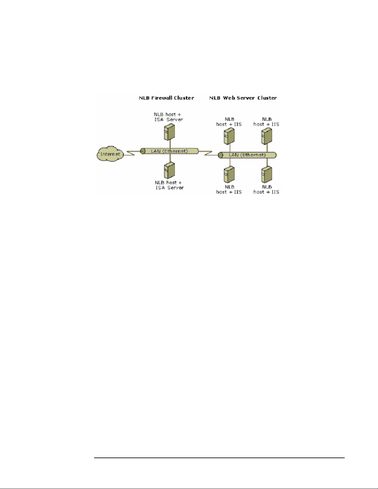
For a detailed discussion of the key features of this technology, as well as its internal
architecture and performance characteristics, see
http://www.microsoft.com/windows2000/docs/NLBtech2.doc.
Figure 1-1 Network Load Balancing example
Introduction
Server Cluster vs. Network Load Balancing
Chapter 1
11
Page 12

Introduction
Cluster terminology
Cluster terminology
A working knowledge of clustering begins with the definition of some common terms.
The following terms are used throughout this document.
Nodes
Individual servers, or members of a cluster, are referred to as nodes or systems (the
terms are used interchangeably). A node can be an active or inactive member of a cluster,
depending on whether or not it is currently online and in communication with the other
cluster nodes. An active node can act as host to one or more cluster groups.
Cluster service
Cluster service refers to the collection of clustering software on each node that manages
all cluster-specific activity.
Shared disks
The shared disks are devices (normally hard drives) that the cluster nodes are attached
to by way of a shared bus. Applications, file shares, and other resources that will be
managed by the cluster are stored on the shared disks.
Resources
Resources are physical or logical entities (such as a file share) managed by the cluster
software. Resources may provide a service to clients or be an integral part of the cluster.
Examples of resources would be physical hardware devices such as disk drives, or logical
items such as IP addresses, network names, applications, and services. Resources are the
basic unit of management by the Cluster service. A resource can only run on a single
node in a cluster at a time, and is said to be online on a node when it is providing its
service on that specific node.
At any given time, a resource can exhibit only one of the following states:
• Offline
• Offline pending
•Online
• Online pending
•Failed
When a resource is offline, it is unavailable for use by a client or another resource. When
a resource is online, it is available for use. The initial state of any resource is offline.
When a resource is in one of the pending states, it is in the process of either being
brought online or taken offline. If the resource cannot be brought online or taken offline
after a specified amount of time, and the resource is set to the failed state, you can
specify the amount of time that Cluster service waits before failing the resource by
setting its pending timeout value in Cluster Administrator.
12
Chapter 1
Page 13

Introduction
Cluster terminology
Resource state changes can occur either manually (when you use Cluster Administrator
to make a state transition) or automatically (during the failover process). When a group
is failed over, the states of each resource are altered according to their dependencies on
the other resources in the group.
Resource dependencies
A dependency is a reliance between two resources that makes it necessary for both
resources to run on the same node (for example, a Network Name resource depending on
an IP address). The only dependency relationships that Cluster service recognizes are
relationships between resources. Cluster service cannot be told, for example, that a
resource depends on a Windows 2003 service; the resource can only be dependent on a
resource representing that service.
Groups
Groups are a collection of resources to be managed as a single unit for configuration and
recovery purposes. Operations performed on a group, such as taking it offline or moving
it to another node, affect all resources contained within that group. Usually a group
contains all the elements needed to run a specific application, and for client systems to
connect to the service provided by the application.
If a resource depends on another resource, each of the resources must be a member of the
same group. In the example of the file share resource, the group containing the file share
must also contain the disk resource and network resources such as the IP address and
NetBIOS name to which clients connect to access the share. All resources within a group
must be online on the same node in the cluster.
NOTE During failover, entire groups are moved from one node to another in the cluster. A single
resource cannot fail from one node to another.
Quorums
Each cluster has a special resource known as the quorum resource. The quorum
provides a means for arbitration leading to node membership and cluster state decisions.
Only one node at a time may own the quorum. That node is designated as the primary
node. When a primary node fails over to a backup node, the backup node takes
ownership of the quorum.
The quorum resource also provides physical storage to maintain the configuration
information for the cluster. This information is kept in the quorum log, which is simply a
configuration database for the cluster. The log holds cluster configuration information
such as which servers are part of the cluster, what resources are installed in the cluster,
and what state those resources are in (for example, online or offline). By default the
quorum log is located at \MSCS\quolog.log.
NOTE Quorums are only used in the Microsoft Cluster Service known as Server Cluster (they
are not used in Network Load Balancing). Therefore, references to quorums throughout
the remainder of this document apply to Server Clusters only.
Chapter 1
13
Page 14

Introduction
Cluster terminology
There are two main reasons why the quorum resource is important in a cluster:
• Consistency—Because the basic idea of a cluster is multiple physical servers acting
as a single virtual server, it is critical that each physical server have a consistent
view of how the cluster is configured. The quorum acts as the definitive repository for
all configuration information relating to the cluster. In the event that the Cluster
Service is unable to read the quorum log, it will not start, since it is unable to
guarantee that the cluster is in a consistent state, which is one of the primary
requirements for a cluster.
• Arbitration—The quorum is used as the tie-breaker to avoid “split-brain” scenarios.
A split-brain scenario occurs when all of the network communication links between
two or more cluster nodes fail. In these cases, the cluster may split into two or more
partitions that cannot communicate with each other. The quorum then guarantees
that any cluster resource is only brought online on one node only. It does this by
allowing the partition that “owns” the quorum to continue, while the other partitions
are evicted from the cluster.
There are two types quorums: the single quorum, and the Majority Node Set (MNS)
quorum. Given the differences in the way that single quorum clusters behave compared
to MNS quorum clusters, care must be taken when deciding which model to choose.
For example, if you only have two nodes in your cluster, the MNS model is not
recommended, as failure of one node will lead to failure of the entire cluster (since a
majority of nodes is impossible). Also, once the cluster is created, you cannot change the
quorum from one type to another. Your decision about the quorum type must be made
during creation of the cluster, and cannot be changed later by simply switching the
cluster quorum resource.
A description of the two quorum types follows.
Single quorum
As mentioned previously, a quorum is basically a configuration database for the cluster,
and is stored in the quorum log file. A single quorum uses a quorum log file that is
located on a single disk hosted on a shared storage interconnect that is accessible by all
nodes in the cluster. Single quorums are available in Windows Server 2003 Enterprise
Edition and Windows Server 2003 Datacenter Edition.
NOTE It is possible to configure clusters to use the local hard disk on one node to store the
quorum, but this is only supported for testing and development purposes, and should not
be used in a production environment. Each node connects to the shared storage through
some type of interconnect, with the storage consisting of either external hard disks
(usually configured as RAID disks), or a storage area network (SAN), where logical slices
of the SAN are presented as physical disks. Also, it is important that the quorum uses a
physical disk resource, as opposed to a disk partition, as the entire physical disk
resource is moved during failover.
14
Chapter 1
Page 15

The following is a sample diagram of a single quorum in a four-node cluster:
Figure 1-2 Single quorum example
Single quorums are sufficient for the majority of situations that most users encounter.
Typical situations include:
Introduction
Cluster terminology
• Highly available data in a single location—Most customers that require their
data to be highly available only need this on a per site basis. If they have multiple
sites, each site has its own cluster. Typical applications that use this type of cluster
include Microsoft SQL Server, file shares, printer queues, and network services (for
example, DHCP & WINS).
• Stateful applications—Applications or Windows NT services that require only a
single instance at any time and require some sort of state to be stored, typically use
single quorums, as they already have some sort of shared storage for maintaining the
state.
Connecting all nodes to a single storage device simplifies the challenge of transferring
control of the data to a backup node. Another advantage to this type is that only one
node needs to remain active in order for the cluster to continue to function.
However, this architecture does have several weaknesses. If the storage device fails, the
entire cluster fails. If the storage area network (SAN) fails, the entire cluster fails. And
while the storage device and SAN can be designed with complete redundancy to
eliminate those possibilities, there is one component in this architecture that can never
be truly redundant — the facility itself.
Floods, fires, earthquakes, extended power failures, and other serious problems will
cause the entire cluster to fail. If your business continuity requirements require that
work continue even if the facility is taken offline, a single quorum cluster solution alone
will not meet your needs.
Chapter 1
15
Page 16

Introduction
Cluster terminology
Majority node set (MNS) quorum
A majority node set quorum appears as a single quorum resource from the perspective of
the server cluster. However, the data is actually stored by default on the system disk of
each node of the cluster. The clustering software ensures that the configuration data
stored on the MNS is kept consistent across the different disks. Majority node set
quorums are available in Windows Server 2003 Enterprise Edition and Windows Server
2003 Datacenter Edition.
As Figure 1-3 shows, majority node set clusters require only that the cluster nodes be
connected by a network. That network doesn't need to be a local area network (LAN),
either. It can be a wide area network (WAN) or a virtual private network (VPN)
connecting cluster nodes in different buildings or even cities. This allows the cluster to
overcome the geographic restrictions imposed by its storage connections.
The following is a sample diagram of an MNS quorum in a four-node cluster:
Figure 1-3 MNS quorum example
While the disks that make up the MNS could in theory be disks on a shared storage
fabric, the MNS implementation provided as part of Windows Server 2003 uses a
directory on each node's local system disk to store the quorum data. If the configuration
of the cluster changes, that change is reflected across the different disks. The change is
only considered to have been committed, or made persistent, if that change is made to:
(<Number of nodes configured in the cluster>/2) + 1
This ensures that a majority of the nodes have an up-to-date copy of the data. The
cluster service itself will only start up and therefore bring resources online if a majority
of the nodes configured as part of the cluster are up and running the cluster service. If
there are fewer nodes, the cluster is said not to have quorum and therefore the cluster
service waits (trying to restart) until more nodes try to join. Only when a majority or
quorum of nodes are available, will the cluster service start up, and bring the resources
online. In this way, because the up-to-date configuration is written to a majority of the
nodes regardless of node failures, the cluster will always guarantee that it starts up with
the latest and most up-to-date configuration.
In the case of a failure or split-brain, all partitions that do not contain a majority of
nodes are terminated. This ensures that if there is a partition running that contains a
majority of the nodes, it can safely start up any resources that are not running on that
partition, safe in the knowledge that it can be the only partition in the cluster that is
running resources (because all other partitions are terminated).
16
Chapter 1
Page 17

Introduction
Cluster terminology
MNS quorums have very strict requirements to ensure they work correctly, and
therefore should only be considered by administrators who fully understand the issues
involved in using MNS-based clusters. Their use should be limited to the following
situations:
• Geographically dispersed clusters—Involves a single MSCS cluster that has
members in multiple geographic sites. While geographic clusters are possible using a
standard quorum, a number of issues arise in terms of presenting the quorum as a
single, logical shared drive among all sites. Majority Node Set quorums solve these
issues by allowing the quorum to be stored on the local hard disk.
NOTE HP does, however, support geographically dispersed clusters with shared quorums
through the use of Cluster Extension XP (CLX) and Continuous Access (CA)
technology on XP storage products.
• Clusters with no shared disks—Some specialized configurations exist that need
tightly consistent cluster features without having shared disks. For example:
— Clusters that host applications that can failover, but where there is some other,
application-specific way to keep data consistent between nodes (for example,
database log shipping for keeping database state up-to-date; file replication for
relatively static data, etc.).
— Clusters that host applications having no persistent data, but need to cooperate in
a tightly coupled way to provide consistent volatile state.
— Independent Software Vendors: by abstracting storage from the Cluster Service, it
provides independent software vendors with much greater flexibility in how they
design sophisticated cluster scenarios.
Heartbeats
Heartbeats are network packets periodically broadcast by each node over the private
network of the cluster. Their purpose is to inform other nodes of its health, configuration,
and network connection status. When heartbeat messages are not received among the
other nodes as expected, the Cluster service interprets it as node failure, and a failover is
initiated.
Virtual servers
Groups that contain an IP address resource and a network name resource (along with
other resources) are published to clients on the network under a unique server name.
Because these groups appear as individual servers to clients, they are called virtual
servers. Users access applications or services on a virtual server in the same way they
would if the application or service were on a physical server. They do not even need to
know that they are connecting to a cluster and have no knowledge of which node they are
really connected to.
Chapter 1
Failover
Failover is the process of moving a group of resources from one node to another in the
case of a failure. For example, in a cluster where Microsoft Internet Information Server
(IIS) is running on node A and node A fails, IIS will failover to node B of the cluster.
17
Page 18

Introduction
Cluster terminology
Failback
Failback is the process of returning a resource or group of resources to the node on which
it was running before a failover occurred. Extending the preceding example, when node
A comes back online, IIS can failback to node A.
18
Chapter 1
Page 19

2 Setup, configuration, validation, and
maintenance of the cluster
The procedures described in this chapter provide step-by-step installation and
configuration directions for the HP Integrity clustered systems running Microsoft
Windows Server 2003, 64-bit Edition.
Chapter 2
19
Page 20

Setup, configuration, validation, and maintenance of the cluster
Verifying minimum software and hardware requirements
Verifying minimum software and hardware
requirements
Use the following procedure to verify that you have all of the required software and
firmware, and have completed all the necessary setup tasks before beginning your
cluster installation.
Step 1. Before installation, see the HP Cluster Configuration Support website for details about
the components that make up a valid cluster configuration. On the website you will find
a support matrix for each clustering solution. Each matrix lists all of the components
necessary to provide a quality-tested and supported solution.
View these support matrices at
http://h18004.www1.hp.com/solutions/enterprise/highavailability/answercenter/configur
ation-all-list.html#03ei. Select the operating system and storage platform of the desired
clustering solution. View the support matrix and verify that you have two or more
supported HP Integrity servers, supported Fibre Channel Adapters (FCA), two or more
supported network adapters, two supported Fibre Channel switches, and one or more
supported shared storage enclosures. Also verify that you have the required drivers for
these components.
Step 2. This step applies only to servers running non-preloaded, Enterprise versions of the OS.
Locate your Microsoft Windows Server 2003, 64-bit Enterprise Edition CD. Use this CD
to install the operating system on each of the nodes that will make up the clustered
system. If you need help with this step, see the appropriate “Windows on Integrity:
Smart Setup Guide” document at http://docs.hp.com/en/windows.html.
NOTE Datacenter versions of Windows Server 2003 always come preloaded on HP Integrity
servers, so this step does not apply to those systems (or to systems on which the
Enterprise edition comes preloaded per the purchase agreement).
Step 3. Locate your Smart Setup CD. Use this CD to install the Support Pack on each node. This
installs or updates your system firmware and operating system drivers. Insert the Smart
Setup CD, click the
Step 4. Locate your Smart Update CD (if shipped with your system). On each node, use this CD
to install any Microsoft quick fix engineering (QFE) updates or security patches that
have been published for the operating system.
Step 5. Locate your HP Storage Enclosure configuration software CD.
Step 6. Locate your HP Storage Enclosure Controller firmware, and verify you have the latest
supported version installed.
Step 7. Locate your HP StorageWorks MultiPath for Windows software.
Support Pack tab, and follow the onscreen instructions.
NOTE You must use MultiPath software if you have redundant paths connected to your Fibre
Channel storage. The reason for installing more than one HBA per cluster is to provide
multiple connections between the clusters and your shared storage (see Figure 2-1).
Multiple HBAs, along with MultiPath software, are highly recommended because they
provide continuous access to your storage system and eliminate single points of failure.
20
Chapter 2
Page 21

Setup, configuration, validation, and maintenance of the cluster
Verifying minimum software and hardware requirements
If you are using single connections between nodes and storage (or one HBA per node),
MultiPath software is not required. However, this option is not recommended.
Step 8. Locate your HP Fibre Channel switch firmware, and verify you have the latest supported
version installed.
Step 9. Verify that you have sufficient administrative rights to install the operating system and
other software onto each node.
Step 10. Verify that all of the required hardware is properly installed and cabled (see Figure 2-1).
For information about best practices for this step, see
http://www.microsoft.com/technet/prodtechnol/windowsserver2003/library/ServerHelp/f5
abf1f9-1d84-4088-ae54-06da05ac9cb4.mspx.
NOTE Figure 2-1 is an example only. It may not represent the actual cabling required by your
system.
Step 11. Determine all of the input parameters required to install your clustered system, and
record them in the table found in the next section (“Gathering all required installation
information” on page 23). Also see the Microsoft discussion of this topic at
http://www.microsoft.com/technet/prodtechnol/windowsserver2003/library/DepKit/64392
d1a-dfe4-41af-a25f-a8ac8a1eda92.mspx.
Step 12. After you have completed all of the previous steps, proceed to the next chapter (“Setup,
configuration, validation, and maintenance of the cluster” on page 19) and begin the
installation.
Chapter 2
21
Page 22

Setup, configuration, validation, and maintenance of the cluster
Verifying minimum software and hardware requirements
Figure 2-1 Example cluster hardware cabling scheme
PDC
Client
ComputerComputer Computer Wor kst at i on Workst atio n Wor kst at i onComputer
Node 1
Shared Storage
NIC-1
NIC-2
Port -1
FC
HBA
MultiPath
(EVA, XP, MSA)
Cli entClient
Switch-1 Switch-2
Team
Public LAN
Private LAN
FC Switch-1
FC Switch-2
Team
Por t- 1
Por t- 2Port -2
MultiPath
Cli entCli entClientClient
`
NIC-1
NIC-2
FC
HBA
Node “n”
(up to 8 nodes total)
22
Chapter 2
Page 23

Setup, configuration, validation, and maintenance of the cluster
Gathering all required installation information
Gathering all required installation information
The following table provides a means for recording the input parameters you will need to
install the operating system and configure the cluster. Write the information in the
“Value” column next to each description.
Table 2-1 Input parameters needed for OS/cluster installation and configuration
Input Description Value
Name for each node:
(Microsoft Windows
Server 2003
supports up to eight
nodes per cluster)
Public network
connection IP
address and subnet
mask for each node:
Node 1: Node 2:
Node 3: Node 4:
Node 5: Node 6:
Node 7: Node 8:
Node 1 Node 2:
IP address:
Subnet mask:
Node 3 Node 4:
IP address:
Subnet mask:
Node 5: Node 6:
IP address:
Subnet mask:
Node 7: Node 8:
IP address:
IP address:
Subnet mask:
IP address:
Subnet mask:
IP address:
Subnet mask:
IP address:
Chapter 2
Subnet mask:
Subnet mask:
23
Page 24

Setup, configuration, validation, and maintenance of the cluster
Gathering all required installation information
Table 2-1 Input parameters needed for OS/cluster installation and configuration
Input Description Value
Private network
connection (cluster
heartbeat) IP
address and subnet
mask for each node:
WWID, slot number,
and bus of each FCA
for each node:
Node 1 Node 2:
IP address:
Subnet mask:
Node 3 Node 4:
IP address:
Subnet mask:
Node 5: Node 6:
IP address:
Subnet mask:
Node 7: Node 8:
IP address:
Subnet mask:
Node 1 Node 2:
FCA 1 WWID:
FCA 1 slot and bus:
FCA 2 WWID:
IP address:
Subnet mask:
IP address:
Subnet mask:
IP address:
Subnet mask:
IP address:
Subnet mask:
FCA 1 WWID:
FCA 1 slot and bus:
FCA 2 WWID:
FCA 2 slot and bus:
Node 3 Node 4:
FCA 1 WWID:
FCA 1 slot and bus:
FCA 2 WWID:
FCA 2 slot and bus:
Node 5: Node 6:
FCA 1 WWID:
FCA 1 slot and bus:
FCA 2 WWID:
FCA 2 slot and bus:
Node 7: Node 8:
FCA 1 WWID:
FCA 1 slot and bus:
FCA 2 WWID:
FCA 2 slot and bus:
FCA 2 slot and bus:
FCA 1 WWID:
FCA 1 slot and bus:
FCA 2 WWID:
FCA 2 slot and bus:
FCA 1 WWID:
FCA 1 slot and bus:
FCA 2 WWID:
FCA 2 slot and bus:
FCA 1 WWID:
FCA 1 slot and bus:
FCA 2 WWID:
FCA 2 slot and bus:
24
Chapter 2
Page 25

Setup, configuration, validation, and maintenance of the cluster
Gathering all required installation information
Table 2-1 Input parameters needed for OS/cluster installation and configuration
Input Description Value
Cluster name:
Cluster IP address
and subnet mask:
Default gateway IP
address:
WINS server IP
address:
DNS IP address:
Local machine
Admin password
(used during OS
installation):
Domain name:
Domain admin user
name and password
(used during OS
installation for
machine to join
domain):
Domain account
user name and
password for cluster
service (this account
has special
privileges on each
cluster node):
IP address:
Subnet mask:
NOTE: For security reasons, do not write the password here!
NOTE: For security reasons, do not write the password here!
NOTE: For security reasons, do not write the password here!
Chapter 2
25
Page 26

Setup, configuration, validation, and maintenance of the cluster
Creating and configuring the cluster
Creating and configuring the cluster
The following sections describe the main steps needed to create and configure your
cluster.
Configuring the public and private networks
NOTE Your private and public NICs must be configured in different subnets, otherwise the
Cluster Service and Cluster Administrator utility will not be able to detect the second
NIC.
In clustered systems, node-to-node communication occurs across a private network,
while client-to-cluster communication occurs across one or more public networks. To
review the Microsoft recommendations and best practices for securing your private and
public networks, see
http://www.microsoft.com/technet/prodtechnol/windowsserver2003/library/ServerHelp/8
7f23f24-474b-4dea-bfb5-cfecb3dc5f1d.mspx.
When configuring your networks, remember the following general guidelines:
• Set your private network IP address to a unique, non-routable value on each cluster,
as discussed in Microsoft Knowledge Base Article Number 142863, “Valid IP
Addressing for a Private Network,” at
http://support.microsoft.com/default.aspx?scid=kb;EN-US;142863.
For example, a valid private IP address of 10.1.1.1 with subnet mask of 255.0.0.0
could be used for node A, while an IP address of 10.1.1.2 with subnet mask of
255.0.0.0 could be used for node B, and so on.
• It is good practice (if possible) to install your private/public NICs in the same slots of
each node in the cluster (private NICs in same slot, public NICs in same slot, etc.)
• It is good practice to use NIC Teaming to provide redundancy of your public network
(see “NIC teaming” on page 28)
NOTE You cannot use NIC Teaming to provide redundancy for your private network. However,
you can provide redundancy for your private network without having it fail over to the
public network by configuring an additional NIC on each cluster member in a different,
non-routable subnet, and setting it for “Internal Cluster communication only”. This
method is described in the Microsoft Knowledge Base Article Number 258750,
“Recommended private "Heartbeat" configuration on a cluster server,” at
http://support.microsoft.com/default.aspx?scid=kb;EN-US;258750.
Private network
Before configuring the private network for your cluster, see the following Microsoft
Knowledge Base articles for Microsoft recommendations and best practices:
• Article number 258750, “Recommended private “Heartbeat” configuration on a
cluster server,” at http://support.microsoft.com/default.aspx?scid=kb;EN-US;258750
• Article Number 193890, “Recommended WINS Configuration for Microsoft Cluster
Server,” at http://support.microsoft.com/default.aspx?scid=kb;EN-US;193890
26
Chapter 2
Page 27

Setup, configuration, validation, and maintenance of the cluster
Creating and configuring the cluster
• Article Number 142863, “Valid IP Addressing for a Private Network,” at
http://support.microsoft.com/default.aspx?scid=kb;EN-US;142863
To configure your private network:
Step 1. Right-click the
My Network Places icon on your desktop, and select Properties.
Step 2. Determine which Local Area Connection icon in the Network Connections window
represents your private network. Right-click that icon, select
Rename, and change its
name to “Private”.
Step 3. Right-click the
Step 4. Click the
Private icon and select Properties.
General tab. Be sure that only the Internet Protocol (TCP/IP) checkbox is selected.
Clear any other checkboxes.
Step 5. If you have a network adapter capable of transmitting at multiple speeds, manually
specify a speed and duplex mode. Do not use an auto-select setting for speed, because
some adapters might drop packets while determining the speed. The speed for the
network adapters must be hard set to the same speed on all nodes according to the card
manufacturer specification.
If you are not sure of the supported speed of your card and connecting devices, Microsoft
recommends setting all devices on that path to 10 Mbs per second and Half Duplex. The
amount of information traveling across the heartbeat network is small, but latency is
critical for communication. This configuration provides adequate bandwidth for reliable
communication. All network adapters in a cluster attached to the same network must be
configured identically to use the same Duplex Mode, Link Speed, Flow Control, and so
on. Contact your adapter manufacturer for specific information about appropriate speed
and duplex settings for your network adapters.
Step 6. Click the
Internet Protocol (TCP/IP) to highlight, and click Properties.
Step 7. Click the
General tab, verify that you have selected a static IP address that is not on the
same subnet or network as any other public network adapter.
For example, suitable IP addresses to use for the private adapters are 10.10.10.10 on
node 1 and 10.10.10.11 on node 2 with a subnet mask of 255.0.0.0. Be sure to use a
different IP address scheme than that used for the public network.
Step 8. Verify that no values are defined in the
addresses
Step 9. Click the
Register this connection’s address in DNS and the Use this connection’s DNS suffix in DNS
registration
Step 10. Click the
NetBIOS over TCP/IP
Step 11. Close the dialog box, and click
This connection has an empty primary WINS address. Do you want to continue?
fields, and click Advanced.
DNS tab, and verify that no values are defined in this field. Be sure that the
checkboxes are cleared.
WINS tab, and verify that no values are defined in this field. Click Disable
.
Yes if the following message appears:
Default Gateway or Use the following DNS server
Step 12. Repeat Step 1 through Step 11 for all remaining nodes in the cluster, using different
static IP addresses.
Chapter 2
27
Page 28

Setup, configuration, validation, and maintenance of the cluster
Creating and configuring the cluster
Public networks
To configure your public networks:
Step 1. Right-click the
My Network Places icon on your desktop, and select Properties.
Step 2. Determine which Local Area Connection icon in the Network Connections window
represents your public network. Right-click that icon, select
Rename, and change the
name to “Public”. If you have more than one public network (recommended), you can
name them “Public-1”, “Public-2”, etc. Repeat for each of your public network connection
icons.
Step 3. Right-click the
Step 4. Click the
Step 5. Click the
Public icon and select Properties.
General tab, click Internet Protocol (TCP/IP) to highlight it, then click Properties.
General tab, and assign the IP Address and Subnet Mask values determined by
your network administrator.
Step 6. Click
OK several times to implement the changes and exit the connection properties
window.
Step 7. Click
Start->Settings->Control Panel and double-click Network Connections. In the Network
Connections Advanced dropdown menu, select
Advanced Settings. In the Connections
box, verify that your connections are listed in the following order:
(1) external public network, (2) internal private network/heartbeat, (3) remote access
connections.
NOTE If your public network paths are teamed, you must put your “teamed” connection at the
top of the list (instead of “external public network”).
Step 8. Repeat Step 1 through Step 7 for each node in the cluster. Be sure to assign a unique IP
address to each node while keeping the subnet mask the same for each.
If you are running a single public network (not recommended), this completes its
configuration. Proceed directly to “Preparing node 1 for clustering” on page 29.
Step 9. If you are running multiple public networks (for example: Public-1, Public-2, etc.), repeat
Step 1 through Step 8 for each network, until all are configured.
Step 10. When all your public networks are configured, continue to the next section (NIC
teaming) to tie them together.
NIC teaming
To configure NIC teaming of your multiple public networks:
Step 1. Double-click the
Network Configuration Utility (NCU) icon in the lower right corner of your
taskbar.
Step 2. In the list that displays in the NCU main window, click each of your public network NICs
to highlight them (there should be one per network), and then click
Team->Properties.
Step 3. The Team Properties window appears. Accept the default settings or change them as
determined by your network administrator, and then click
Step 4. Right-click the
My Network Places desktop icon, and select Properties.
OK to create the NIC team.
28
Chapter 2
Page 29

Setup, configuration, validation, and maintenance of the cluster
Creating and configuring the cluster
Step 5. A new connection icon now appears in the Network Connections window. This is the
single “teamed” connection that now represents (to the outside world) the multiple
networks you just teamed together. You must assign this new teamed network an IP
address, subnet mask, etc.
Step 6. Right-click the new icon, select
Step 7. Right-click the
Step 8. Click the
Properties.
click
Step 9. Click the
TEAM icon and select Properties.
General tab, click the Internet Protocol (TCP/IP) item to highlight it, and then
General tab, and assign the IP Address and Subnet Mask values determined by
Rename, and change the name to “TEAM”.
your network administrator.
Step 10. Click
OK several times to implement the changes and exit the connection properties
window.
NOTE Microsoft does not recommend the use of NIC Teaming for the private network.
Preparing node 1 for clustering
To prepare node 1 for clustering:
Step 1. Power on and boot node 1.
Step 2. Click
Step 3. Click the
Start->Settings->Control Panel->HP Management Agents.
Services tab, select Cluster Information on the right side, and then click Add to
move it to the left side. This action starts the Cluster Agent service on the node, which
forwards cluster status information and makes it accessible from the System
Management Homepage. Click
OK.
Step 4. Right-click the
Step 5. Click the
My Computer desktop icon, and select Properties.
Computer Name tab, and click Change. Select the Domain Name radio button, and
enter the domain name determined by your network administrator. Reboot when
prompted and log into the new domain.
Configuring the shared storage
To review the Microsoft recommendations and best practices for securing the shared
data in your cluster, see
http://www.microsoft.com/technet/prodtechnol/windowsserver2003/library/ServerHelp/b
7f1f826-5fe9-4c96-bb24-7b2d053db992.mspx.
To configure the shared storage:
Step 1. Power on node 1 and log into the domain.
Step 2. Install and configure your HP StorageWorks MultiPath for Windows software.
For an overview and general discussion of the MultiPath software, see
http://h18006.www1.hp.com/products/sanworks/secure-path/spwin.html.
Chapter 2
29
Page 30

Setup, configuration, validation, and maintenance of the cluster
Creating and configuring the cluster
For technical documentation regarding the installation, configuration, or
troubleshooting of the MultiPath software, see
http://h20000.www2.hp.com/bizsupport/TechSupport/Home.jsp?locale=en_US&prodType
Id=12169&prodSeriesId=315586.
HP Multi-Pathing IO (MPIO) Device Specific Module software can be used as an
alternative to HP StorageWorks Secure Path to provide multipath support. For
information and to download the MPIO Device Specific Module software, see
http://h20000.www2.hp.com/bizsupport/TechSupport/SoftwareIndex.jsp?lang=en&cc=us
&prodNameId=421495&prodTypeId=18964&prodSeriesId=421492&swLang=13&taskId
=135&swEnvOID=1113.
NOTE You must use MultiPath software if more than one host bus adapter (HBA) is installed in
each cluster. The reason for installing more than one HBA per cluster is to provide
multiple connections between the clusters and your shared storage (see Figure 2-1).
Multiple HBAs, along with MultiPath software, are highly recommended because they
provide continuous access to your storage system and eliminate single points of failure.
If you are using single connections between nodes and storage (or one HBA per node),
MultiPath software is not required. However this option is not recommended.
Step 3. Connect your node to the shared storage.
Step 4. For details about creating logical drives, see your storage system user guide. Using those
directions, create a logical drive with at least 510 MB of space.
NOTE While the absolute minimum allowable size is 50 MB, Microsoft recommends at least 500
MB for the cluster Quorum drive (specifying 510 MB ensures that the disk size is at least
500 MB of formatted space). The extra space in the logical drive is used for internal disk
size calculations by your Storage Array Configuration Utility. For information about this
topic, see the Microsoft Knowledge Base article EN-US280345, “Quorum Drive
Configuration Information,” at
http://support.microsoft.com/default.aspx?scid=kb;EN-US;280345. Information about
disk sizes is also available in the cluster node Help documentation.
Server clusters do not support GPT shared disks. For information about this topic, see
the Knowledge Base article EN-US284134, “Server clusters do not support GPT shared
disks,” at http://support.microsoft.com/default.aspx?scid=kb;en-us;284134.
Step 5. After the shared storage drives are configured, select
Tools
->Computer Management, and then select Disk Management. Use this tool to create
Start->Programs->Administrative
the NTFS partitions (make them the MBR type).
When running Disk Management, complete all of the following tasks:
• Allow Disk Management to write a disk signature when initializing the disk.
• Establish unique drive letters for all shared disks, typically starting in the middle of
the alphabet to avoid local and network drive letters.
• Establish meaningful volume label name on shared disks, such as: “Quorum Disk Q”
or “SQL Disk S.”
30
Chapter 2
Page 31

Setup, configuration, validation, and maintenance of the cluster
Creating and configuring the cluster
NOTE Do not upgrade the logical drives from Basic to Dynamic. Microsoft Cluster Services do
not support Dynamic disks.
Step 6. Close Disk Management for Microsoft Windows Server 2003, 64-bit Edition.
Preparing node 2+ for clustering
To prepare node 2 (or more) for clustering:
Step 1. Power on and boot node 2.
Step 2. Click
Step 3. Click the
Start->Control Panel->HP Management Agents.
Services tab, select Cluster Information on the right side, and then click Add to
move it to the left side. This action starts the Cluster Agent service on the node, which
forwards cluster status information and makes it accessible from the System
Management Homepage.
Step 4. Right-click the
Step 5. Click the
My Computer desktop icon, and select Properties.
Computer Name tab, and click Change. Select the Domain Name radio button and
enter the domain name determined by your network administrator. Reboot when
prompted and log into the new domain.
Step 6. Install the MultiPath software on this node.
Step 7. All other nodes should be powered Off before completing this step. Click
Start->Programs->Administrative Tools->Computer Management, and select Disk
Management
. Use this tool to confirm that consistent drive letters and volume labels have
been established by the first node.
Step 8. Repeat Step 1 through Step 7 for each of the remaining nodes in the cluster (Microsoft
Windows Server 2003, 64-bit Edition supports a maximum of 8 cluster nodes).
Creating the cluster
To create the cluster using node 1:
Chapter 2
Step 1. Power all the nodes off except node 1, and log into the domain.
Step 2. On node 1, select
Step 3. In the “Action” dropdown list, select
Start->Programs->Administrative Tools->Cluster Administrator.
Create New Cluster, click OK, and click Next. The
Cluster Creation wizard begins.
Step 4. Assign a
Step 5. Be sure the computer name appears in the Server Name list box and click
Cluster Name, keep the default value for Domain, and click Next.
Next. Cluster
analysis begins.
Step 6. The Tasks Completed bar grows longer during this process. The color of the bar should
be blue. It should stay blue right up until the end, until the bar is full, and then it will
turn green. Click
Next.
31
Page 32

Setup, configuration, validation, and maintenance of the cluster
Creating and configuring the cluster
NOTE If the Tasks Completed bar turns red at any time during this process, this indicates
there was an error and cluster analysis was aborted. See the log file to locate the source
of the problem. Debug or reconfigure as necessary and try again.
Step 7. Enter the cluster IP address and click
Next. The cluster IP address must be on the same
subnet as the public network.
Step 8. Enter the
Cluster User Account Name and Password and click Next.
Step 9. A detailed summary of the proposed cluster displays. Review this information, then click
Next to begin the cluster creation process.
Step 10. The Tasks Completed bar grows longer during this process. The color of the bar should
be blue. It should stay blue right up until the end, until the bar is full, and then it will
turn green. Click
Next.
NOTE If the Tasks Completed bar turns red at any time during this process, this indicates
there was an error and cluster creation was aborted. See the log file to locate the source
of the problem. Debug or reconfigure as necessary and try again.
Step 11. When the wizard finishes creating the cluster, click
Next->Finish.
Joining node 2+ to the cluster
NOTE Microsoft Windows Server 2003 supports a maximum of 8 cluster nodes. Repeat the
following steps for each additional node. These steps can be completed from node 1 or
node 2+.
To join node 2+ to the cluster:
Step 1. Power on node 2, and log into the domain.
Step 2. Select
Step 3. Select
Step 4. In the “Action” dropdown list, select
Step 5. In the Welcome to Add Nodes wizard, click
Step 6. Enter the name of the node you want to add under
Start->Programs->Administrative Tools->Cluster Administrator.
File->Open Connection.
Add Nodes to Cluster and click OK.
Next.
Computer Name, click Add, then click
Next. Cluster analysis begins.
NOTE At this point you could list all of your nodes at the same time by entering the name of
each one and clicking
Add. This action would add all of them to the cluster in a single
step. However, there is a risk with this method. If there is any kind of problem during
the “add” process that causes it to abort mid-stream, it will be much more difficult to
determine which node caused the problem. For this reason, HP recommends that you
add the nodes one at a time, as described here.
Step 7. The Tasks Complete bar grows longer during this process. The color of the bar should be
blue. It should stay blue right up until the end, until the bar is full, and then it will turn
green. Click
Next.
32
Chapter 2
Page 33

Setup, configuration, validation, and maintenance of the cluster
Creating and configuring the cluster
NOTE If the Tasks Completed bar turns red at any time during this process, this indicates
there was an error and cluster analysis was aborted. See the log file to locate the source
of the problem. Debug or reconfigure as necessary and try again.
Step 8. Enter the
Password for the cluster service account and click Next.
Step 9. A detailed summary of the proposed cluster displays. Review this information, then click
Next to begin the node addition process.
Step 10. The Tasks Completed bar grows longer during this process. The color of the bar should
be blue. It should stay blue right up until the end, until the bar is full, and then it will
turn green. Click
Next.
NOTE If the Tasks Completed bar turns red at any time during this process, this indicates
there was an error and node addition was aborted. See the log file to locate the source of
the problem. Debug or reconfigure as necessary and try again.
Step 11. When the wizard finishes adding the node, click
Next and then click Finish.
Step 12. Repeat Step 1 through Step 11 for each node you want to add to the cluster.
Configuring private/public network role and priority settings
To configure the private and public network Role settings:
Step 1. Select
Step 2. In the left pane under
Start->Programs->Administrative Tools->Cluster Administrator.
Cluster Configuration->Networks, right-click Private and select
Properties.
Step 3. Click the
activate it. Click
Step 4. In the same network folder (Cluster Configuration->Networks), right-click
select
Step 5. Click the
Apply and OK to apply the changes.
General tab, and click Internal Cluster Communications only (private network) to
Apply->OK.
Public and
Properties.
General tab, and click All communications (mixed network) to activate it. Click
To configure the network Priority settings:
Step 1. Select
Step 2. In the left pane, right-click the cluster name and select
Start->Programs->Administrative Tools->Cluster Administrator.
Properties.
Step 3. In the Network Priority tab, locate the “Networks used” list. Be sure the line labeled
“Private” is at the top of this list. “Private” must be at the top, above the line labeled
“Public”. If you need to change the order, select “Private” and click
upward. Click
Apply and OK to apply the changes.
Move Up to move it
Chapter 2
33
Page 34

Setup, configuration, validation, and maintenance of the cluster
Validating cluster operation
Validating cluster operation
To validate your cluster installation, use one or both of the following methods from any
node in the cluster:
Method 1
Step 1. Select Start->Programs->Administrative Tools->Cluster Administrator and connect to the
cluster.
Step 2. If your cluster has only 2 nodes, right-click one of the cluster groups and select
Group
. If there are more than 2 nodes in your cluster, select Move Group, and then choose
which node you want to fail over to.
Step 3. Verify the group fails over and all resources come online.
Step 4. Right-click the same cluster group and select
Step 5. Verify the group fails over to the previous node and all resources come online.
Step 6. Repeat Step 1 through Step 5 for each resource group in the cluster, if desired.
Move Group.
Move
Method 2
This method of cluster validation is optional and not required.
The Cluster Diagnostics and Verification tool (ClusDiag.exe) is a GUI utility that helps
system administrators perform diagnostic tests on pre-production or production clusters,
and then view the resulting log files to debug any problems or failures discovered.You
can also use it to generate various cluster-related reports from the information gathered
during the diagnostic process.
Step 1. Install the Microsoft cluster diagnostics tool (ClusDiag.exe). Download this tool from
http://www.microsoft.com/downloads/details.aspx?displaylang=en&familyid=B898F58788C3-4602-84DE-B9BC63F02825.
Step 2. Select
Start->Programs->Cluster Diagnostics Tool to launch the utility.
Step 3. Select
Step 4. Click
Step 5. Testing begins. Upon completion, click
Step 6. If desired, see the log file for more detailed information.
NOTE If you experience problems validating your cluster using either of the methods listed
Online, select a cluster name from the dropdown list, and click OK.
Too ls->Run Test, and in the Run Test dialog box select the type of test you want to
run from the dropdown list. Click
• Basic: tests for a fixed period of time
• Regular: tests for a user-defined period of time
above, see the Microsoft “MS Cluster Server Troubleshooting and Maintenance”
information at
http://www.microsoft.com/technet/archive/winntas/support/mscstswp.mspx.
34
Launch. The two test types are:
OK to see the results.
Chapter 2
Page 35

Setup, configuration, validation, and maintenance of the cluster
Validating cluster operation
Also see the “Troubleshooting cluster node installations” section at
http://www.microsoft.com/technet/prodtechnol/windowsserver2003/library/ServerHelp/7
9c8164e-ee17-4e6d-a46f-f3db9869d9ea.mspx.
Chapter 2
35
Page 36

Setup, configuration, validation, and maintenance of the cluster
Upgrading individual nodes in the future
Upgrading individual nodes in the future
At some point after your initial installation and configuration you will want to upgrade
the software and drivers installed on each node in your cluster, as well as add the latest
system updates and security fixes. This is an inevitable system administration chore
that must be done regularly if you want to keep your Integrity servers up-to-date and
secure.
With clustered systems you no longer have to do all of your maintenance during those
rare times when all of your users are off-line. Instead, you simply wait until a
convenient, off-peak time when one of the nodes in the cluster can be taken off-line for
maintenance and its workload distributed among the remaining nodes. Before the
upgrade, however, you must evaluate the entire system to verify that the remaining
nodes can handle the increased capacity (while the node being upgraded is taken
off-line).
Basically, you pick the node you want to upgrade, then use the Cluster Administrator to
move all of the clustered resources onto one or more of the remaining nodes. This can
also be accomplished using scripts. Once all of the resources have been failed-over to the
other nodes, the first node is free and ready for upgrading. For more information about
how to upgrade your Integrity servers with the latest drivers and QFEs, see the latest
Smart Setup Guide for Integrity servers at http://docs.hp.com/en/windows.html, under
the section, “Windows 64-bit on HP Integrity Servers”.
Once the upgrade to the first node is complete, reboot it if necessary and move the
resources back to it. As soon as possible you should repeat this process to upgrade the
other nodes in the cluster. This minimizes the amount of time the nodes are operating
with different versions of software or drivers.
36
Chapter 2
 Loading...