

Page 1
User Service Guide
HP Integrity rx4640 Server
Manufacturing Part Number: A6961-96013
First Edition
August 2006
© Copyright 2006 Hewlett-Packard Development Company, L.P.
Page 2

Legal Notices
Copyright Notices. © Copyright 2006 Hewlett-Packard Development Company, L.P.
The information contained herein is subject to change without notice.
The only warranties for HP products and services are set forth in the express warranty statements
accompanying such products and services. Nothing herein should be construed as constituting an additional
warranty. HP shall not be liable for technical or editorial errors or omissions contained herein.
Printed in U.S.A.
Intel, Intel Inside, Itanium, and the Intel Inside logo are trademarks or registered trademarks of Intel
Corporation or its subsidiaries in the United States and other countries.
Linux is a U.S. registered trademark of Linus Torvalds.
Microsoft and Windows are U.S. registered trademarks of Microsoft Corporation.
2
Page 3

About This Document
Intended Audience . . . . . . . . . . . . . . . . . . . . . . . . . . . . . . . . . . . . . . . . . . . . . . . . . . . . . . . . . . . . . . . . . . . 15
New and Changed Information in This Edition . . . . . . . . . . . . . . . . . . . . . . . . . . . . . . . . . . . . . . . . . . . . 15
Publishing History . . . . . . . . . . . . . . . . . . . . . . . . . . . . . . . . . . . . . . . . . . . . . . . . . . . . . . . . . . . . . . . . . . . 15
Document Organization. . . . . . . . . . . . . . . . . . . . . . . . . . . . . . . . . . . . . . . . . . . . . . . . . . . . . . . . . . . . . . . 16
Typographic Conventions . . . . . . . . . . . . . . . . . . . . . . . . . . . . . . . . . . . . . . . . . . . . . . . . . . . . . . . . . . . . . 16
HP-UX Release Name and Release Identifier . . . . . . . . . . . . . . . . . . . . . . . . . . . . . . . . . . . . . . . . . . . . . 17
Related Documents . . . . . . . . . . . . . . . . . . . . . . . . . . . . . . . . . . . . . . . . . . . . . . . . . . . . . . . . . . . . . . . . . . 17
HP Encourages Your Comments . . . . . . . . . . . . . . . . . . . . . . . . . . . . . . . . . . . . . . . . . . . . . . . . . . . . . . . . 18
1. Introduction
Server Overview . . . . . . . . . . . . . . . . . . . . . . . . . . . . . . . . . . . . . . . . . . . . . . . . . . . . . . . . . . . . . . . . . . . . . 20
Server Dimensions and Weight . . . . . . . . . . . . . . . . . . . . . . . . . . . . . . . . . . . . . . . . . . . . . . . . . . . . . . . . . 21
Server Components . . . . . . . . . . . . . . . . . . . . . . . . . . . . . . . . . . . . . . . . . . . . . . . . . . . . . . . . . . . . . . . . . . 22
Processors . . . . . . . . . . . . . . . . . . . . . . . . . . . . . . . . . . . . . . . . . . . . . . . . . . . . . . . . . . . . . . . . . . . . . . . . 22
Memory . . . . . . . . . . . . . . . . . . . . . . . . . . . . . . . . . . . . . . . . . . . . . . . . . . . . . . . . . . . . . . . . . . . . . . . . . . 22
PCI Riser . . . . . . . . . . . . . . . . . . . . . . . . . . . . . . . . . . . . . . . . . . . . . . . . . . . . . . . . . . . . . . . . . . . . . . . . . 22
Internal Core I/O. . . . . . . . . . . . . . . . . . . . . . . . . . . . . . . . . . . . . . . . . . . . . . . . . . . . . . . . . . . . . . . . . . . 22
External Core I/O . . . . . . . . . . . . . . . . . . . . . . . . . . . . . . . . . . . . . . . . . . . . . . . . . . . . . . . . . . . . . . . . . . 22
Power Supply Unit . . . . . . . . . . . . . . . . . . . . . . . . . . . . . . . . . . . . . . . . . . . . . . . . . . . . . . . . . . . . . . . . . 23
Motherboard Manageability. . . . . . . . . . . . . . . . . . . . . . . . . . . . . . . . . . . . . . . . . . . . . . . . . . . . . . . . . . 23
Enhanced Server Manageability Using Management Processor . . . . . . . . . . . . . . . . . . . . . . . . . . . . . 23
Hard Disk Drives . . . . . . . . . . . . . . . . . . . . . . . . . . . . . . . . . . . . . . . . . . . . . . . . . . . . . . . . . . . . . . . . . . 23
Supported Operating Systems. . . . . . . . . . . . . . . . . . . . . . . . . . . . . . . . . . . . . . . . . . . . . . . . . . . . . . . . . . 24
Contents
2. Controls, Ports, and LEDs
Front Panel Controls, Ports, and LEDs . . . . . . . . . . . . . . . . . . . . . . . . . . . . . . . . . . . . . . . . . . . . . . . . . . 26
Hard Disk Drive LED Indicators . . . . . . . . . . . . . . . . . . . . . . . . . . . . . . . . . . . . . . . . . . . . . . . . . . . . . . 27
DVD/DVD-R/DVD-RW Drives . . . . . . . . . . . . . . . . . . . . . . . . . . . . . . . . . . . . . . . . . . . . . . . . . . . . . . . . 28
Rear Panel Controls, Ports, and LEDs . . . . . . . . . . . . . . . . . . . . . . . . . . . . . . . . . . . . . . . . . . . . . . . . . . . 28
Power Supply Status LEDs . . . . . . . . . . . . . . . . . . . . . . . . . . . . . . . . . . . . . . . . . . . . . . . . . . . . . . . . . . 29
Management Processor LAN LEDs . . . . . . . . . . . . . . . . . . . . . . . . . . . . . . . . . . . . . . . . . . . . . . . . . . . . 29
Locator LED and Button . . . . . . . . . . . . . . . . . . . . . . . . . . . . . . . . . . . . . . . . . . . . . . . . . . . . . . . . . . . . 30
Gigabit Ethernet Card LAN Ports (Core I/O) . . . . . . . . . . . . . . . . . . . . . . . . . . . . . . . . . . . . . . . . . . . . 30
Internal Controls, Ports, and LEDs . . . . . . . . . . . . . . . . . . . . . . . . . . . . . . . . . . . . . . . . . . . . . . . . . . . . . 31
QuickFind Diagnostic Panel. . . . . . . . . . . . . . . . . . . . . . . . . . . . . . . . . . . . . . . . . . . . . . . . . . . . . . . . . . 31
I/O Baseboard LED Indicators . . . . . . . . . . . . . . . . . . . . . . . . . . . . . . . . . . . . . . . . . . . . . . . . . . . . . . . . 32
3. Powering Off and Powering On the Server
Power States. . . . . . . . . . . . . . . . . . . . . . . . . . . . . . . . . . . . . . . . . . . . . . . . . . . . . . . . . . . . . . . . . . . . . . . . 34
Powering Off the Server. . . . . . . . . . . . . . . . . . . . . . . . . . . . . . . . . . . . . . . . . . . . . . . . . . . . . . . . . . . . . . . 34
Powering Off the Server Using the iLO MP . . . . . . . . . . . . . . . . . . . . . . . . . . . . . . . . . . . . . . . . . . . . . 34
Powering Off the Server Manually . . . . . . . . . . . . . . . . . . . . . . . . . . . . . . . . . . . . . . . . . . . . . . . . . . . . 35
Powering On the Server. . . . . . . . . . . . . . . . . . . . . . . . . . . . . . . . . . . . . . . . . . . . . . . . . . . . . . . . . . . . . . . 35
Powering On the Server Using the iLO MP . . . . . . . . . . . . . . . . . . . . . . . . . . . . . . . . . . . . . . . . . . . . . 35
Powering On the Server Manually . . . . . . . . . . . . . . . . . . . . . . . . . . . . . . . . . . . . . . . . . . . . . . . . . . . . 36
3
Page 4

Contents
4. Removing and Replacing Components
Safety Information . . . . . . . . . . . . . . . . . . . . . . . . . . . . . . . . . . . . . . . . . . . . . . . . . . . . . . . . . . . . . . . . . . . 38
Service Tools Required. . . . . . . . . . . . . . . . . . . . . . . . . . . . . . . . . . . . . . . . . . . . . . . . . . . . . . . . . . . . . . . . 38
Accessing a Rack Mounted Server . . . . . . . . . . . . . . . . . . . . . . . . . . . . . . . . . . . . . . . . . . . . . . . . . . . . . . 38
Extending the Server from the Rack . . . . . . . . . . . . . . . . . . . . . . . . . . . . . . . . . . . . . . . . . . . . . . . . . . . 39
Inserting the Server into the Rack . . . . . . . . . . . . . . . . . . . . . . . . . . . . . . . . . . . . . . . . . . . . . . . . . . . . 39
Accessing a Pedestal Mounted Server . . . . . . . . . . . . . . . . . . . . . . . . . . . . . . . . . . . . . . . . . . . . . . . . . . . 40
Removing and Replacing the Front Bezel. . . . . . . . . . . . . . . . . . . . . . . . . . . . . . . . . . . . . . . . . . . . . . . . . 41
Removing the Front Bezel . . . . . . . . . . . . . . . . . . . . . . . . . . . . . . . . . . . . . . . . . . . . . . . . . . . . . . . . . . . 41
Replacing the Front Bezel . . . . . . . . . . . . . . . . . . . . . . . . . . . . . . . . . . . . . . . . . . . . . . . . . . . . . . . . . . . 41
Removing and Replacing the Front and Top Covers . . . . . . . . . . . . . . . . . . . . . . . . . . . . . . . . . . . . . . . . 42
Removing the Front Cover . . . . . . . . . . . . . . . . . . . . . . . . . . . . . . . . . . . . . . . . . . . . . . . . . . . . . . . . . . . 42
Replacing the Front Cover . . . . . . . . . . . . . . . . . . . . . . . . . . . . . . . . . . . . . . . . . . . . . . . . . . . . . . . . . . . 43
Removing the Top Cover. . . . . . . . . . . . . . . . . . . . . . . . . . . . . . . . . . . . . . . . . . . . . . . . . . . . . . . . . . . . . 43
Replacing the Top Cover. . . . . . . . . . . . . . . . . . . . . . . . . . . . . . . . . . . . . . . . . . . . . . . . . . . . . . . . . . . . . 44
Removing and Replacing the Memory Extender Board. . . . . . . . . . . . . . . . . . . . . . . . . . . . . . . . . . . . . . 44
Removing the Memory Extender Board . . . . . . . . . . . . . . . . . . . . . . . . . . . . . . . . . . . . . . . . . . . . . . . . 44
Replacing the Memory Extender Board . . . . . . . . . . . . . . . . . . . . . . . . . . . . . . . . . . . . . . . . . . . . . . . . 46
Removing and Replacing Server Memory DIMMs. . . . . . . . . . . . . . . . . . . . . . . . . . . . . . . . . . . . . . . . . . 46
Removing Server Memory DIMMs . . . . . . . . . . . . . . . . . . . . . . . . . . . . . . . . . . . . . . . . . . . . . . . . . . . . 46
Installing Memory DIMMs. . . . . . . . . . . . . . . . . . . . . . . . . . . . . . . . . . . . . . . . . . . . . . . . . . . . . . . . . . . 47
16 DIMM Memory Extender Board Layout . . . . . . . . . . . . . . . . . . . . . . . . . . . . . . . . . . . . . . . . . . . . . 49
32 DIMM Memory Extender Board Layout . . . . . . . . . . . . . . . . . . . . . . . . . . . . . . . . . . . . . . . . . . . . . 50
Removing and Replacing the Processor Extender Board. . . . . . . . . . . . . . . . . . . . . . . . . . . . . . . . . . . . . 52
Removing the Processor Extender Board . . . . . . . . . . . . . . . . . . . . . . . . . . . . . . . . . . . . . . . . . . . . . . . 52
Replacing the Processor Extender Board . . . . . . . . . . . . . . . . . . . . . . . . . . . . . . . . . . . . . . . . . . . . . . . 54
Removing and Replacing a Processor . . . . . . . . . . . . . . . . . . . . . . . . . . . . . . . . . . . . . . . . . . . . . . . . . . . . 55
Processor Load Order . . . . . . . . . . . . . . . . . . . . . . . . . . . . . . . . . . . . . . . . . . . . . . . . . . . . . . . . . . . . . . . 55
Removing a Processor . . . . . . . . . . . . . . . . . . . . . . . . . . . . . . . . . . . . . . . . . . . . . . . . . . . . . . . . . . . . . . . 56
Replacing a Processor . . . . . . . . . . . . . . . . . . . . . . . . . . . . . . . . . . . . . . . . . . . . . . . . . . . . . . . . . . . . . . . 58
Removing and Replacing Hot-Swap Chassis Fans. . . . . . . . . . . . . . . . . . . . . . . . . . . . . . . . . . . . . . . . . . 63
Removing a Hot-Swap Chassis Fan Unit . . . . . . . . . . . . . . . . . . . . . . . . . . . . . . . . . . . . . . . . . . . . . . . 63
Replacing a Hot-Swap Chassis Fan Unit. . . . . . . . . . . . . . . . . . . . . . . . . . . . . . . . . . . . . . . . . . . . . . . . 65
Removing and Replacing the I/O Baseboard . . . . . . . . . . . . . . . . . . . . . . . . . . . . . . . . . . . . . . . . . . . . . . 66
Removing the I/O Baseboard . . . . . . . . . . . . . . . . . . . . . . . . . . . . . . . . . . . . . . . . . . . . . . . . . . . . . . . . . 66
Replacing the I/O Baseboard . . . . . . . . . . . . . . . . . . . . . . . . . . . . . . . . . . . . . . . . . . . . . . . . . . . . . . . . . 69
Removing and Replacing Hot-Plug PCI-X Cards . . . . . . . . . . . . . . . . . . . . . . . . . . . . . . . . . . . . . . . . . . . 71
PCI-X Specifications . . . . . . . . . . . . . . . . . . . . . . . . . . . . . . . . . . . . . . . . . . . . . . . . . . . . . . . . . . . . . . . . 71
Operating System Support for Hot-Plug PCI-X Operations. . . . . . . . . . . . . . . . . . . . . . . . . . . . . . . . . 72
PCI-X Hardware and Software Interfaces. . . . . . . . . . . . . . . . . . . . . . . . . . . . . . . . . . . . . . . . . . . . . . . 73
PCI-X Slot Locations and Configurations . . . . . . . . . . . . . . . . . . . . . . . . . . . . . . . . . . . . . . . . . . . . . . . 74
Hot-Plug Operation Procedures . . . . . . . . . . . . . . . . . . . . . . . . . . . . . . . . . . . . . . . . . . . . . . . . . . . . . . . 77
Removing and Replacing OLX Dividers . . . . . . . . . . . . . . . . . . . . . . . . . . . . . . . . . . . . . . . . . . . . . . . . . . 81
Removing an OLX Divider . . . . . . . . . . . . . . . . . . . . . . . . . . . . . . . . . . . . . . . . . . . . . . . . . . . . . . . . . . . 81
Replacing an OLX Divider . . . . . . . . . . . . . . . . . . . . . . . . . . . . . . . . . . . . . . . . . . . . . . . . . . . . . . . . . . . 84
Removing and Replacing Core I/O Cards . . . . . . . . . . . . . . . . . . . . . . . . . . . . . . . . . . . . . . . . . . . . . . . . . 85
4
Page 5

Contents
PCI Slot Locations and Configurations . . . . . . . . . . . . . . . . . . . . . . . . . . . . . . . . . . . . . . . . . . . . . . . . . 85
Removing and Replacing the SCSI Core I/O Card . . . . . . . . . . . . . . . . . . . . . . . . . . . . . . . . . . . . . . . . 86
Removing and Replacing the LAN Core I/O Card . . . . . . . . . . . . . . . . . . . . . . . . . . . . . . . . . . . . . . . . 88
Removing and Replacing the Server Battery . . . . . . . . . . . . . . . . . . . . . . . . . . . . . . . . . . . . . . . . . . . . . . 89
Removing and Replacing Hard Disk Drives . . . . . . . . . . . . . . . . . . . . . . . . . . . . . . . . . . . . . . . . . . . . . . . 90
Removing a Hard Disk Drive . . . . . . . . . . . . . . . . . . . . . . . . . . . . . . . . . . . . . . . . . . . . . . . . . . . . . . . . . 90
Replacing a Hard Disk Drive . . . . . . . . . . . . . . . . . . . . . . . . . . . . . . . . . . . . . . . . . . . . . . . . . . . . . . . . . 90
Removing and Replacing the SCSI Backplane Board . . . . . . . . . . . . . . . . . . . . . . . . . . . . . . . . . . . . . . . 93
Removing the SCSI Backplane Board . . . . . . . . . . . . . . . . . . . . . . . . . . . . . . . . . . . . . . . . . . . . . . . . . . 93
Replacing the SCSI Backplane Board . . . . . . . . . . . . . . . . . . . . . . . . . . . . . . . . . . . . . . . . . . . . . . . . . . 94
Removing and Replacing the Midplane Riser Board . . . . . . . . . . . . . . . . . . . . . . . . . . . . . . . . . . . . . . . . 95
Removing the Midplane Riser Board . . . . . . . . . . . . . . . . . . . . . . . . . . . . . . . . . . . . . . . . . . . . . . . . . . . 95
Replacing the Midplane Riser Board . . . . . . . . . . . . . . . . . . . . . . . . . . . . . . . . . . . . . . . . . . . . . . . . . . . 97
Removing and Replacing the Power Supplies . . . . . . . . . . . . . . . . . . . . . . . . . . . . . . . . . . . . . . . . . . . . . 98
Power Supply Load Order . . . . . . . . . . . . . . . . . . . . . . . . . . . . . . . . . . . . . . . . . . . . . . . . . . . . . . . . . . . 98
Removing a Hot-Swap Power Supply . . . . . . . . . . . . . . . . . . . . . . . . . . . . . . . . . . . . . . . . . . . . . . . . . . 98
Replacing a Hot-Swap Power Supply. . . . . . . . . . . . . . . . . . . . . . . . . . . . . . . . . . . . . . . . . . . . . . . . . . . 99
Removing and Replacing the Power Distribution Board . . . . . . . . . . . . . . . . . . . . . . . . . . . . . . . . . . . . 100
Removing the Power Distribution Board. . . . . . . . . . . . . . . . . . . . . . . . . . . . . . . . . . . . . . . . . . . . . . . 100
Replacing the Power Distribution Board. . . . . . . . . . . . . . . . . . . . . . . . . . . . . . . . . . . . . . . . . . . . . . . 101
Removing and Replacing the DVD Drive . . . . . . . . . . . . . . . . . . . . . . . . . . . . . . . . . . . . . . . . . . . . . . . . 102
Removing the DVD Drive . . . . . . . . . . . . . . . . . . . . . . . . . . . . . . . . . . . . . . . . . . . . . . . . . . . . . . . . . . . 102
Replacing the DVD Drive . . . . . . . . . . . . . . . . . . . . . . . . . . . . . . . . . . . . . . . . . . . . . . . . . . . . . . . . . . . 103
Removing and Replacing the DVD I/O Board . . . . . . . . . . . . . . . . . . . . . . . . . . . . . . . . . . . . . . . . . . . . 104
Removing the DVD I/O Board . . . . . . . . . . . . . . . . . . . . . . . . . . . . . . . . . . . . . . . . . . . . . . . . . . . . . . . 104
Replacing the DVD I/O Board . . . . . . . . . . . . . . . . . . . . . . . . . . . . . . . . . . . . . . . . . . . . . . . . . . . . . . . 106
Removing and Replacing the Display Board . . . . . . . . . . . . . . . . . . . . . . . . . . . . . . . . . . . . . . . . . . . . . 107
Removing the Display Board . . . . . . . . . . . . . . . . . . . . . . . . . . . . . . . . . . . . . . . . . . . . . . . . . . . . . . . . 107
Replacing the Display Board . . . . . . . . . . . . . . . . . . . . . . . . . . . . . . . . . . . . . . . . . . . . . . . . . . . . . . . . 108
Removing and Replacing the QuickFind Diagnostic Board. . . . . . . . . . . . . . . . . . . . . . . . . . . . . . . . . . 109
Removing the QuickFind Diagnostic Board . . . . . . . . . . . . . . . . . . . . . . . . . . . . . . . . . . . . . . . . . . . . 109
Replacing the QuickFind Diagnostic Board . . . . . . . . . . . . . . . . . . . . . . . . . . . . . . . . . . . . . . . . . . . . 110
5. Troubleshooting
Troubleshooting Tips . . . . . . . . . . . . . . . . . . . . . . . . . . . . . . . . . . . . . . . . . . . . . . . . . . . . . . . . . . . . . . . . 112
Troubleshooting Methodology . . . . . . . . . . . . . . . . . . . . . . . . . . . . . . . . . . . . . . . . . . . . . . . . . . . . . . . 112
Possible Problems. . . . . . . . . . . . . . . . . . . . . . . . . . . . . . . . . . . . . . . . . . . . . . . . . . . . . . . . . . . . . . . . . . . 113
The Server Does Not Power Up . . . . . . . . . . . . . . . . . . . . . . . . . . . . . . . . . . . . . . . . . . . . . . . . . . . . . . 113
The Server Does Not Boot . . . . . . . . . . . . . . . . . . . . . . . . . . . . . . . . . . . . . . . . . . . . . . . . . . . . . . . . . . 113
The Server Has Intermittent Failures. . . . . . . . . . . . . . . . . . . . . . . . . . . . . . . . . . . . . . . . . . . . . . . . . 114
The Server LED or Diagnostic LEDs Are Not On and No Error Messages Appear . . . . . . . . . . . . . 115
Power Shuts Off and Does Not Come Back On . . . . . . . . . . . . . . . . . . . . . . . . . . . . . . . . . . . . . . . . . . 115
Troubleshooting Using LED Indicators . . . . . . . . . . . . . . . . . . . . . . . . . . . . . . . . . . . . . . . . . . . . . . . . . 116
Front Control Panel LED Indicators . . . . . . . . . . . . . . . . . . . . . . . . . . . . . . . . . . . . . . . . . . . . . . . . . . 117
Hard Disk Drive LED Indicators . . . . . . . . . . . . . . . . . . . . . . . . . . . . . . . . . . . . . . . . . . . . . . . . . . . . . 118
DVD/DVD-R/DVD-RW Drive LED Indicators . . . . . . . . . . . . . . . . . . . . . . . . . . . . . . . . . . . . . . . . . . . 118
5
Page 6

Contents
QuickFind Diagnostic Panel LED Indicators . . . . . . . . . . . . . . . . . . . . . . . . . . . . . . . . . . . . . . . . . . . 119
I/O Baseboard LED Indicators . . . . . . . . . . . . . . . . . . . . . . . . . . . . . . . . . . . . . . . . . . . . . . . . . . . . . . . 121
Power Supply Status LED Indicators . . . . . . . . . . . . . . . . . . . . . . . . . . . . . . . . . . . . . . . . . . . . . . . . . 123
iLO MP LAN LED Indicators. . . . . . . . . . . . . . . . . . . . . . . . . . . . . . . . . . . . . . . . . . . . . . . . . . . . . . . . 124
Locator LED and Button . . . . . . . . . . . . . . . . . . . . . . . . . . . . . . . . . . . . . . . . . . . . . . . . . . . . . . . . . . . 124
PCI-X LEDs and Hardware Errors . . . . . . . . . . . . . . . . . . . . . . . . . . . . . . . . . . . . . . . . . . . . . . . . . . . 125
Diagnostics . . . . . . . . . . . . . . . . . . . . . . . . . . . . . . . . . . . . . . . . . . . . . . . . . . . . . . . . . . . . . . . . . . . . . . . . 127
Online Diagnostics/Exercisers . . . . . . . . . . . . . . . . . . . . . . . . . . . . . . . . . . . . . . . . . . . . . . . . . . . . . . . 127
Offline Support Tool Availability . . . . . . . . . . . . . . . . . . . . . . . . . . . . . . . . . . . . . . . . . . . . . . . . . . . . . 128
Offline Support Tools List . . . . . . . . . . . . . . . . . . . . . . . . . . . . . . . . . . . . . . . . . . . . . . . . . . . . . . . . . . 128
General Diagnostic Tools . . . . . . . . . . . . . . . . . . . . . . . . . . . . . . . . . . . . . . . . . . . . . . . . . . . . . . . . . . . 129
Fault Management Overview. . . . . . . . . . . . . . . . . . . . . . . . . . . . . . . . . . . . . . . . . . . . . . . . . . . . . . . . 129
HP-UX Fault Management. . . . . . . . . . . . . . . . . . . . . . . . . . . . . . . . . . . . . . . . . . . . . . . . . . . . . . . . . . 129
Recommended Cleaning Procedures . . . . . . . . . . . . . . . . . . . . . . . . . . . . . . . . . . . . . . . . . . . . . . . . . . . . 130
Where to Get Help . . . . . . . . . . . . . . . . . . . . . . . . . . . . . . . . . . . . . . . . . . . . . . . . . . . . . . . . . . . . . . . . . . 131
Information to Collect Before you Contact Support . . . . . . . . . . . . . . . . . . . . . . . . . . . . . . . . . . . . . . 131
Online Support . . . . . . . . . . . . . . . . . . . . . . . . . . . . . . . . . . . . . . . . . . . . . . . . . . . . . . . . . . . . . . . . . . . 131
Phone Support. . . . . . . . . . . . . . . . . . . . . . . . . . . . . . . . . . . . . . . . . . . . . . . . . . . . . . . . . . . . . . . . . . . . 132
A. Parts Information
Field Replaceable Parts List . . . . . . . . . . . . . . . . . . . . . . . . . . . . . . . . . . . . . . . . . . . . . . . . . . . . . . . . . . 134
B. Booting the Operating System
Operating Systems Supported on HP Integrity Servers . . . . . . . . . . . . . . . . . . . . . . . . . . . . . . . . . . . . 140
Configuring System Boot Options . . . . . . . . . . . . . . . . . . . . . . . . . . . . . . . . . . . . . . . . . . . . . . . . . . . . . . 140
Booting and Shutting Down HP-UX . . . . . . . . . . . . . . . . . . . . . . . . . . . . . . . . . . . . . . . . . . . . . . . . . . . . 141
Adding HP-UX to the Boot Options List . . . . . . . . . . . . . . . . . . . . . . . . . . . . . . . . . . . . . . . . . . . . . . . 142
Standard HP-UX Booting . . . . . . . . . . . . . . . . . . . . . . . . . . . . . . . . . . . . . . . . . . . . . . . . . . . . . . . . . . . 143
Single-User Mode HP-UX Booting . . . . . . . . . . . . . . . . . . . . . . . . . . . . . . . . . . . . . . . . . . . . . . . . . . . . 144
LVM Maintenance Mode HP-UX Booting . . . . . . . . . . . . . . . . . . . . . . . . . . . . . . . . . . . . . . . . . . . . . . 146
Shutting Down HP-UX . . . . . . . . . . . . . . . . . . . . . . . . . . . . . . . . . . . . . . . . . . . . . . . . . . . . . . . . . . . . . 146
Booting and Shutting Down HP OpenVMS . . . . . . . . . . . . . . . . . . . . . . . . . . . . . . . . . . . . . . . . . . . . . . 147
Adding HP OpenVMS to the Boot Options List . . . . . . . . . . . . . . . . . . . . . . . . . . . . . . . . . . . . . . . . . 147
Booting HP OpenVMS . . . . . . . . . . . . . . . . . . . . . . . . . . . . . . . . . . . . . . . . . . . . . . . . . . . . . . . . . . . . . 148
Shutting Down HP OpenVMS . . . . . . . . . . . . . . . . . . . . . . . . . . . . . . . . . . . . . . . . . . . . . . . . . . . . . . . 150
Booting and Shutting Down Microsoft Windows . . . . . . . . . . . . . . . . . . . . . . . . . . . . . . . . . . . . . . . . . . 151
Adding Microsoft Windows to the Boot Options List . . . . . . . . . . . . . . . . . . . . . . . . . . . . . . . . . . . . . 151
Booting the Microsoft Windows Operating System . . . . . . . . . . . . . . . . . . . . . . . . . . . . . . . . . . . . . . 152
Shutting Down Microsoft Windows . . . . . . . . . . . . . . . . . . . . . . . . . . . . . . . . . . . . . . . . . . . . . . . . . . . 153
Booting and Shutting Down Linux . . . . . . . . . . . . . . . . . . . . . . . . . . . . . . . . . . . . . . . . . . . . . . . . . . . . . 155
Adding Linux to the Boot Options List . . . . . . . . . . . . . . . . . . . . . . . . . . . . . . . . . . . . . . . . . . . . . . . . 155
Booting the Red Hat Enterprise Linux Operating System . . . . . . . . . . . . . . . . . . . . . . . . . . . . . . . . 156
Booting the SuSE Linux Enterprise Server Operating System. . . . . . . . . . . . . . . . . . . . . . . . . . . . . 157
Shutting Down Linux . . . . . . . . . . . . . . . . . . . . . . . . . . . . . . . . . . . . . . . . . . . . . . . . . . . . . . . . . . . . . . 158
C. Utilities
6
Page 7

Contents
Extensible Firmware Interface Boot Manager . . . . . . . . . . . . . . . . . . . . . . . . . . . . . . . . . . . . . . . . . . . . 160
EFI Commands . . . . . . . . . . . . . . . . . . . . . . . . . . . . . . . . . . . . . . . . . . . . . . . . . . . . . . . . . . . . . . . . . . . 162
EFI/POSSE Commands . . . . . . . . . . . . . . . . . . . . . . . . . . . . . . . . . . . . . . . . . . . . . . . . . . . . . . . . . . . . . . 164
help . . . . . . . . . . . . . . . . . . . . . . . . . . . . . . . . . . . . . . . . . . . . . . . . . . . . . . . . . . . . . . . . . . . . . . . . . . . . 164
baud . . . . . . . . . . . . . . . . . . . . . . . . . . . . . . . . . . . . . . . . . . . . . . . . . . . . . . . . . . . . . . . . . . . . . . . . . . . . 166
boottest . . . . . . . . . . . . . . . . . . . . . . . . . . . . . . . . . . . . . . . . . . . . . . . . . . . . . . . . . . . . . . . . . . . . . . . . . 166
cpuconfig . . . . . . . . . . . . . . . . . . . . . . . . . . . . . . . . . . . . . . . . . . . . . . . . . . . . . . . . . . . . . . . . . . . . . . . . 167
ioconfig. . . . . . . . . . . . . . . . . . . . . . . . . . . . . . . . . . . . . . . . . . . . . . . . . . . . . . . . . . . . . . . . . . . . . . . . . . 168
default . . . . . . . . . . . . . . . . . . . . . . . . . . . . . . . . . . . . . . . . . . . . . . . . . . . . . . . . . . . . . . . . . . . . . . . . . . 169
errdump. . . . . . . . . . . . . . . . . . . . . . . . . . . . . . . . . . . . . . . . . . . . . . . . . . . . . . . . . . . . . . . . . . . . . . . . . 169
info . . . . . . . . . . . . . . . . . . . . . . . . . . . . . . . . . . . . . . . . . . . . . . . . . . . . . . . . . . . . . . . . . . . . . . . . . . . . . 170
lanaddress . . . . . . . . . . . . . . . . . . . . . . . . . . . . . . . . . . . . . . . . . . . . . . . . . . . . . . . . . . . . . . . . . . . . . . . 175
monarch. . . . . . . . . . . . . . . . . . . . . . . . . . . . . . . . . . . . . . . . . . . . . . . . . . . . . . . . . . . . . . . . . . . . . . . . . 176
pdt . . . . . . . . . . . . . . . . . . . . . . . . . . . . . . . . . . . . . . . . . . . . . . . . . . . . . . . . . . . . . . . . . . . . . . . . . . . . . 176
sysmode . . . . . . . . . . . . . . . . . . . . . . . . . . . . . . . . . . . . . . . . . . . . . . . . . . . . . . . . . . . . . . . . . . . . . . . . . 177
Specifying SCSI Parameters . . . . . . . . . . . . . . . . . . . . . . . . . . . . . . . . . . . . . . . . . . . . . . . . . . . . . . . . . . 178
Using the SCSI Setup Utility. . . . . . . . . . . . . . . . . . . . . . . . . . . . . . . . . . . . . . . . . . . . . . . . . . . . . . . . 178
Using the Boot Configuration Menu . . . . . . . . . . . . . . . . . . . . . . . . . . . . . . . . . . . . . . . . . . . . . . . . . . . . 184
Boot From File . . . . . . . . . . . . . . . . . . . . . . . . . . . . . . . . . . . . . . . . . . . . . . . . . . . . . . . . . . . . . . . . . . . 184
Add Boot Entry . . . . . . . . . . . . . . . . . . . . . . . . . . . . . . . . . . . . . . . . . . . . . . . . . . . . . . . . . . . . . . . . . . . 185
Edit Boot Entry . . . . . . . . . . . . . . . . . . . . . . . . . . . . . . . . . . . . . . . . . . . . . . . . . . . . . . . . . . . . . . . . . . . 185
Remove Boot Entry . . . . . . . . . . . . . . . . . . . . . . . . . . . . . . . . . . . . . . . . . . . . . . . . . . . . . . . . . . . . . . . . 186
BootNext Configuration . . . . . . . . . . . . . . . . . . . . . . . . . . . . . . . . . . . . . . . . . . . . . . . . . . . . . . . . . . . . 186
AutoBoot Configuration . . . . . . . . . . . . . . . . . . . . . . . . . . . . . . . . . . . . . . . . . . . . . . . . . . . . . . . . . . . . 187
Driver Configuration . . . . . . . . . . . . . . . . . . . . . . . . . . . . . . . . . . . . . . . . . . . . . . . . . . . . . . . . . . . . . . 187
Driver Configuration . . . . . . . . . . . . . . . . . . . . . . . . . . . . . . . . . . . . . . . . . . . . . . . . . . . . . . . . . . . . . . 188
Console Configuration . . . . . . . . . . . . . . . . . . . . . . . . . . . . . . . . . . . . . . . . . . . . . . . . . . . . . . . . . . . . . 189
System Reset . . . . . . . . . . . . . . . . . . . . . . . . . . . . . . . . . . . . . . . . . . . . . . . . . . . . . . . . . . . . . . . . . . . . . 190
Using the System Configuration Menu . . . . . . . . . . . . . . . . . . . . . . . . . . . . . . . . . . . . . . . . . . . . . . . . 191
Using the Security Configuration Menu . . . . . . . . . . . . . . . . . . . . . . . . . . . . . . . . . . . . . . . . . . . . . . . 192
Index . . . . . . . . . . . . . . . . . . . . . . . . . . . . . . . . . . . . . . . . . . . . . . . . . . . . . . . . . . . . . . . . . . . . . . 193
7
Page 8

Contents
8
Page 9

Tables
Table 1. Publishing History Details . . . . . . . . . . . . . . . . . . . . . . . . . . . . . . . . . . . . . . . . . . . . . . . . . . 15
Table 2. HP-UX 11i Releases. . . . . . . . . . . . . . . . . . . . . . . . . . . . . . . . . . . . . . . . . . . . . . . . . . . . . . . . 17
Table 1-1. Server Dimensions . . . . . . . . . . . . . . . . . . . . . . . . . . . . . . . . . . . . . . . . . . . . . . . . . . . . . . . 21
Table 3-1. Power States . . . . . . . . . . . . . . . . . . . . . . . . . . . . . . . . . . . . . . . . . . . . . . . . . . . . . . . . . . . . 34
Table 4-1. Quads on the 16 DIMM Memory Extender Board . . . . . . . . . . . . . . . . . . . . . . . . . . . . . . 49
Table 4-2. DIMM Filler Requirements for 16 DIMM Extender Board . . . . . . . . . . . . . . . . . . . . . . . 50
Table 4-3. Quads on the Optional 32 DIMM Memory Extender Board. . . . . . . . . . . . . . . . . . . . . . . 51
Table 4-4. DIMM Filler Requirements for 32 DIMM Extender Board . . . . . . . . . . . . . . . . . . . . . . . 51
Table 4-5. Processor Load Order . . . . . . . . . . . . . . . . . . . . . . . . . . . . . . . . . . . . . . . . . . . . . . . . . . . . . 55
Table 4-6. Hot-Plug Operation and OS Compatibility . . . . . . . . . . . . . . . . . . . . . . . . . . . . . . . . . . . . 72
Table 4-7. Hot-Plug Hardware and Software Interfaces and OS Availability . . . . . . . . . . . . . . . . . 73
Table 4-8. PCI-X Card vs. Slot Frequency/Bus Mode Compatibility for Shared Slots . . . . . . . . . . . 75
Table 5-1. Front Control Panel LED Definitions . . . . . . . . . . . . . . . . . . . . . . . . . . . . . . . . . . . . . . . 117
Table 5-2. Hot-Swap Disk Drive LED Definitions . . . . . . . . . . . . . . . . . . . . . . . . . . . . . . . . . . . . . . 118
Table 5-3. DVD Drive LED Definitions. . . . . . . . . . . . . . . . . . . . . . . . . . . . . . . . . . . . . . . . . . . . . . . 118
Table 5-4. QuickFind Diagnostic Panel LED Definitions. . . . . . . . . . . . . . . . . . . . . . . . . . . . . . . . . 119
Table 5-5. I/O Baseboard LEDs, Buttons and Sensors. . . . . . . . . . . . . . . . . . . . . . . . . . . . . . . . . . . 122
Table 5-6. Power Supply Status LED . . . . . . . . . . . . . . . . . . . . . . . . . . . . . . . . . . . . . . . . . . . . . . . . 123
Table 5-7. iLO MP LED Status Descriptions . . . . . . . . . . . . . . . . . . . . . . . . . . . . . . . . . . . . . . . . . . 124
Table 5-8. PCI-X LED Descriptions. . . . . . . . . . . . . . . . . . . . . . . . . . . . . . . . . . . . . . . . . . . . . . . . . . 125
Table 5-9. Online Support Tools List. . . . . . . . . . . . . . . . . . . . . . . . . . . . . . . . . . . . . . . . . . . . . . . . . 128
Table 5-10. Offline Support Tools List . . . . . . . . . . . . . . . . . . . . . . . . . . . . . . . . . . . . . . . . . . . . . . . 128
Table 5-11. General Diagnostic Tools List . . . . . . . . . . . . . . . . . . . . . . . . . . . . . . . . . . . . . . . . . . . . 129
Table 5-12. Cleaning . . . . . . . . . . . . . . . . . . . . . . . . . . . . . . . . . . . . . . . . . . . . . . . . . . . . . . . . . . . . . 130
Table A-1. Parts List . . . . . . . . . . . . . . . . . . . . . . . . . . . . . . . . . . . . . . . . . . . . . . . . . . . . . . . . . . . . . 134
Table C-1. EFI Commands. . . . . . . . . . . . . . . . . . . . . . . . . . . . . . . . . . . . . . . . . . . . . . . . . . . . . . . . . 162
Table C-2. Communications Parameters . . . . . . . . . . . . . . . . . . . . . . . . . . . . . . . . . . . . . . . . . . . . . 166
Table C-3. Console Output Devices. . . . . . . . . . . . . . . . . . . . . . . . . . . . . . . . . . . . . . . . . . . . . . . . . . 188
Table C-4. Console Output Devices. . . . . . . . . . . . . . . . . . . . . . . . . . . . . . . . . . . . . . . . . . . . . . . . . . 189
Table C-5. Console Output Devices. . . . . . . . . . . . . . . . . . . . . . . . . . . . . . . . . . . . . . . . . . . . . . . . . . 190
Table C-6. Console Output Devices. . . . . . . . . . . . . . . . . . . . . . . . . . . . . . . . . . . . . . . . . . . . . . . . . . 191
9
Page 10

Tables
10
Page 11

Figures
Figure 1-1. HP Integrity rx4640 Server with Front Bezel. . . . . . . . . . . . . . . . . . . . . . . . . . . . . . . . . 20
Figure 1-2. HP Integrity rx4640 Server (front view with bezel removed) . . . . . . . . . . . . . . . . . . . . 21
Figure 1-3. HP Integrity rx4640 Server (rear view). . . . . . . . . . . . . . . . . . . . . . . . . . . . . . . . . . . . . . 21
Figure 2-1. Front View with Bezel . . . . . . . . . . . . . . . . . . . . . . . . . . . . . . . . . . . . . . . . . . . . . . . . . . . 26
Figure 2-2. Accessing the Control Panel. . . . . . . . . . . . . . . . . . . . . . . . . . . . . . . . . . . . . . . . . . . . . . . 26
Figure 2-3. Control Panel LEDs . . . . . . . . . . . . . . . . . . . . . . . . . . . . . . . . . . . . . . . . . . . . . . . . . . . . . 27
Figure 2-4. Hard Disk Drive LED Indicators . . . . . . . . . . . . . . . . . . . . . . . . . . . . . . . . . . . . . . . . . . . 27
Figure 2-5. DVD–ROM Drive . . . . . . . . . . . . . . . . . . . . . . . . . . . . . . . . . . . . . . . . . . . . . . . . . . . . . . . 28
Figure 2-6. Rack Mount and Pedestal Rear View. . . . . . . . . . . . . . . . . . . . . . . . . . . . . . . . . . . . . . . . 28
Figure 2-7. Power Supply Status LEDs . . . . . . . . . . . . . . . . . . . . . . . . . . . . . . . . . . . . . . . . . . . . . . . 29
Figure 2-8. MP LAN LEDs . . . . . . . . . . . . . . . . . . . . . . . . . . . . . . . . . . . . . . . . . . . . . . . . . . . . . . . . . 29
Figure 2-9. Core I/O LAN Port LEDs . . . . . . . . . . . . . . . . . . . . . . . . . . . . . . . . . . . . . . . . . . . . . . . . . 30
Figure 2-10. QuickFind Diagnostic Panel. . . . . . . . . . . . . . . . . . . . . . . . . . . . . . . . . . . . . . . . . . . . . . 31
Figure 2-11. I/O Baseboard LEDs, Buttons, and Sensors . . . . . . . . . . . . . . . . . . . . . . . . . . . . . . . . . 32
Figure 4-1. Accessing 25MM Torx Screws . . . . . . . . . . . . . . . . . . . . . . . . . . . . . . . . . . . . . . . . . . . . . 39
Figure 4-2. Pedestal Mounted HP Integrity rx4640 Server. . . . . . . . . . . . . . . . . . . . . . . . . . . . . . . . 40
Figure 4-3. Removing and Replacing the Front Bezel . . . . . . . . . . . . . . . . . . . . . . . . . . . . . . . . . . . . 41
Figure 4-4. Removing and Replacing the Front Cover. . . . . . . . . . . . . . . . . . . . . . . . . . . . . . . . . . . . 42
Figure 4-5. Removing and Replacing the Top Cover . . . . . . . . . . . . . . . . . . . . . . . . . . . . . . . . . . . . . 43
Figure 4-6. Opening the Memory Extender Board Latches . . . . . . . . . . . . . . . . . . . . . . . . . . . . . . . 45
Figure 4-7. Removing and Replacing the Memory Extender Board. . . . . . . . . . . . . . . . . . . . . . . . . 45
Figure 4-8. Inserting DIMM into Extender Board Slot . . . . . . . . . . . . . . . . . . . . . . . . . . . . . . . . . . . 48
Figure 4-9. 16 DIMM Extender Board Slot IDs . . . . . . . . . . . . . . . . . . . . . . . . . . . . . . . . . . . . . . . . . 49
Figure 4-10. 32 DIMM Extender Board Slot IDs . . . . . . . . . . . . . . . . . . . . . . . . . . . . . . . . . . . . . . . . 50
Figure 4-11. Opening the Processor Extender Board Latches . . . . . . . . . . . . . . . . . . . . . . . . . . . . . 53
Figure 4-12. Removing and Replacing the Processor Extender Board. . . . . . . . . . . . . . . . . . . . . . . 53
Figure 4-13. Processor Slot Locations on the Processor Extender Board . . . . . . . . . . . . . . . . . . . . . 56
Figure 4-14. Removing the Processor Sequencer . . . . . . . . . . . . . . . . . . . . . . . . . . . . . . . . . . . . . . . 57
Figure 4-15. Unlocking the Processor from the Processor Extender Board. . . . . . . . . . . . . . . . . . . 58
Figure 4-16. CPU 1 Socket Unlocked . . . . . . . . . . . . . . . . . . . . . . . . . . . . . . . . . . . . . . . . . . . . . . . . . 59
Figure 4-17. Processor Cable Routed Correctly. . . . . . . . . . . . . . . . . . . . . . . . . . . . . . . . . . . . . . . . . 60
Figure 4-18. Locking the Processor to the Processor Extender Board . . . . . . . . . . . . . . . . . . . . . . . 61
Figure 4-19. Installing Sequencer on Extender Board . . . . . . . . . . . . . . . . . . . . . . . . . . . . . . . . . . . 62
Figure 4-20. Removing and Replacing the Chassis Fans 0 and 1. . . . . . . . . . . . . . . . . . . . . . . . . . . 64
Figure 4-21. Removing and Replacing the Chassis Fan 2 . . . . . . . . . . . . . . . . . . . . . . . . . . . . . . . . . 65
Figure 4-22. I/O Baseboard Locking Lever . . . . . . . . . . . . . . . . . . . . . . . . . . . . . . . . . . . . . . . . . . . . 67
Figure 4-23. Removing the I/O Baseboard . . . . . . . . . . . . . . . . . . . . . . . . . . . . . . . . . . . . . . . . . . . . . 68
Figure 4-24. I/O Baseboard Switches. . . . . . . . . . . . . . . . . . . . . . . . . . . . . . . . . . . . . . . . . . . . . . . . . 69
Figure 4-25. Slot ID Numbering . . . . . . . . . . . . . . . . . . . . . . . . . . . . . . . . . . . . . . . . . . . . . . . . . . . . . 76
Figure 4-26. PCI-X OLX Divider Layout . . . . . . . . . . . . . . . . . . . . . . . . . . . . . . . . . . . . . . . . . . . . . . 78
Figure 4-27. Inserting PCI-X Card . . . . . . . . . . . . . . . . . . . . . . . . . . . . . . . . . . . . . . . . . . . . . . . . . . . 79
Figure 4-28. Opening and Closing the OLX Divider Latch. . . . . . . . . . . . . . . . . . . . . . . . . . . . . . . . 82
Figure 4-29. Removing and Replacing the OLX Divider. . . . . . . . . . . . . . . . . . . . . . . . . . . . . . . . . . 83
11
Page 12

Figures
Figure 4-30. Slot ID Numbering . . . . . . . . . . . . . . . . . . . . . . . . . . . . . . . . . . . . . . . . . . . . . . . . . . . . . 85
Figure 4-31. SCSI I/O Card Latch Location. . . . . . . . . . . . . . . . . . . . . . . . . . . . . . . . . . . . . . . . . . . . 86
Figure 4-32. Inserting SCSI I/O Card . . . . . . . . . . . . . . . . . . . . . . . . . . . . . . . . . . . . . . . . . . . . . . . . 87
Figure 4-33. LAN I/O Card Latch Location . . . . . . . . . . . . . . . . . . . . . . . . . . . . . . . . . . . . . . . . . . . . 88
Figure 4-34. Battery Location on the I/O Baseboard . . . . . . . . . . . . . . . . . . . . . . . . . . . . . . . . . . . . 89
Figure 4-35. Hard Disk Drive and Slot Locations on the Front of the Server . . . . . . . . . . . . . . . . . 91
Figure 4-36. Removing and Replacing a Hard Disk Drive in Slot 2 . . . . . . . . . . . . . . . . . . . . . . . . . 91
Figure 4-37. Installing a Volume Filler in Slot 2 . . . . . . . . . . . . . . . . . . . . . . . . . . . . . . . . . . . . . . . . 92
Figure 4-38. Removing and Replacing the SCSI Backplane Board . . . . . . . . . . . . . . . . . . . . . . . . . 94
Figure 4-39. Removing and Replacing the Midplane Riser Board . . . . . . . . . . . . . . . . . . . . . . . . . . 96
Figure 4-40. Removing and Replacing the Hot-Swap Power Supply. . . . . . . . . . . . . . . . . . . . . . . . . 99
Figure 4-41. Removing and Replacing the Power Distribution Board . . . . . . . . . . . . . . . . . . . . . . 101
Figure 4-42. Removing and Replacing the DVD Drive. . . . . . . . . . . . . . . . . . . . . . . . . . . . . . . . . . . 103
Figure 4-43. Removing and Replacing the DVD I/O Board . . . . . . . . . . . . . . . . . . . . . . . . . . . . . . 105
Figure 4-44. Removing and Replacing the Display Board . . . . . . . . . . . . . . . . . . . . . . . . . . . . . . . . 108
Figure 4-45. Removing and Replacing the QuickFind Diagnostic Board. . . . . . . . . . . . . . . . . . . . 110
Figure 5-1. Front Control Panel . . . . . . . . . . . . . . . . . . . . . . . . . . . . . . . . . . . . . . . . . . . . . . . . . . . . 117
Figure 5-2. Hot-Swap Disk Drive LED Indicators . . . . . . . . . . . . . . . . . . . . . . . . . . . . . . . . . . . . . . 118
Figure 5-3. DVD–ROM Drive . . . . . . . . . . . . . . . . . . . . . . . . . . . . . . . . . . . . . . . . . . . . . . . . . . . . . . 118
Figure 5-4. QuickFind Diagnostic Label. . . . . . . . . . . . . . . . . . . . . . . . . . . . . . . . . . . . . . . . . . . . . . 119
Figure 5-5. I/O Baseboard LEDs, Buttons and Sensors. . . . . . . . . . . . . . . . . . . . . . . . . . . . . . . . . . 121
Figure 5-6. Power Supply Status LED . . . . . . . . . . . . . . . . . . . . . . . . . . . . . . . . . . . . . . . . . . . . . . . 123
Figure 5-7. iLO MP LAN LEDs . . . . . . . . . . . . . . . . . . . . . . . . . . . . . . . . . . . . . . . . . . . . . . . . . . . . . 124
Figure C-1. EFI Boot Sequence . . . . . . . . . . . . . . . . . . . . . . . . . . . . . . . . . . . . . . . . . . . . . . . . . . . . . 160
12
Page 13

Figures
13
Page 14

Figures
14
Page 15
About This Document
This document provides information and instructions on servicing and troubleshooting the HP Integrity
rx4640 server.
The document printing date and part number indicate the document’s current edition. The printing date
changes when a new edition is printed. Minor changes may be made at reprint without changing the printing
date. The document part number changes when extensive changes are made.
Document updates may be issued between editions to correct errors or document product changes. To ensure
that you receive the updated or new editions, you should subscribe to the appropriate product support service.
See your HP sales representative for details.
The latest version of this document can be found on line at http://www.docs.hp.com.
Intended Audience
This document is intended to provide technical product and support information for authorized service
providers, system administrators, and HP support personnel.
This document is not a tutorial.
New and Changed Information in This Edition
This guide has been updated with:
• This document is being updated as part of the continuous product improvement (CPE) initiative to
enhance the current HP Integrity BL60p server blade documentation.
Publishing History
The publishing history below identifies the edition dates of this manual. Updates are made to this publication
on an unscheduled, as needed, basis. The updates will consist of a complete replacement manual and
pertinent on-line or CD documentation.
Table 1 Publishing History Details
Document
Manufacturing
Part Number
A6961-96013 HP-UX, Windows®,
Operating Systems
Supported
Linux®, OpenVMS®
Supported Product Versions
rx4640 August 2006
Publication
Date
15
Page 16

Document Organization
This guide is divided into the following chapters.
Chapter 1 Introduction Use this chapter to learn about the features and specifications of the HP
Integrity rx4640 server.
Chapter 2 Controls, Ports, and LEDs Use this chapter to learn about the locations of the external
controls, ports, and LEDs on the server.
Chapter 3 Powering Off and Powering On the Server Use this chapter to learn about powering
the server off and on.
Chapter 4 Removing and Replacing Components Use this chapter to learn how to remove and
replace the field replaceable components (FRUs) on the server.
Chapter 5 Troubleshooting Use this chapter to learn about troubleshooting problems you may
encounter with the server.
Appendix A Parts Information Use this appendix to learn the location and part numbers of the server
components.
Appendix B Operating System Boot and Shutdown Use this appendix to learn about booting and
shutting down the operating system on the server.
Appendix C Utilities Use this appendix for information regarding the utilities available for the server.
Appendix D Console Setup and Connection Use this appendix to learn about the process for setting
up a console session and connecting to the server.
Typographic Conventions
This document uses the following conventions.
WAR NING A warning lists requirements that you must meet to avoid personal injury.
CAUTION A caution provides information required to avoid losing data or avoid losing system
functionality.
NOTE A note highlights useful information such as restrictions, recommendations, or important
details about HP product features.
Book Title The title of a book. On the Web and on the Instant Information CD, it may be a hot link to
the book itself.
KeyCap The name of a keyboard key or graphical interface item (such as buttons, tabs, and menu
items). Note that
Emphasis Text that is emphasized.
Bold Text that is strongly emphasized.
Bold The defined use of an important word or phrase.
Return and Enter both refer to the same key.
ComputerOut Text displayed by the computer.
UserInput Commands and other text that you type.
16
Page 17
Command A command name or qualified command phrase.
Option An available option.
Screen Output Example of computer screen output.
[] The contents are optional in formats and command descriptions. If the contents are a list
separated by |, you must select one of the items.
{} The contents are required in formats and command descriptions. If the contents are a list
separated by |, you must select one of the items.
... The preceding element may be repeated an arbitrary number of times.
| Separates items in a list of choices.
HP-UX Release Name and Release Identifier
Each HP-UX 11i release has an associated release name and release identifier. The uname (1) command with
the -r option returns the release identifier. This table shows the releases available for HP-UX 11i.
Table 2 HP-U X 1 1i Rel ea se s
Release Identifier Release Name Supported Processor Architecture
B.11.11 HP-UX 11i v1 PA-RISC
B.11.20 HP-UX 11i v1.5 Intel® Itanium®
B.11.22 HP-UX 11i v1.6 Intel Itanium
B.11.23 HP-UX 11i v2.0 Intel Itanium
Related Documents
You can find other information on HP server hardware management, Microsoft® Windows®, and diagnostic
support tools in the following publications.
Web Site for HP Technical Documentation:
http://docs.hp.com
Server Hardware Information:
http://docs.hp.com/hpux/hw/
Windows Operating System Information
You can find information about administration of the Microsoft Windows operating system at the following
Web sites, among others:
• http://docs.hp.com/windows_nt/
• http://www.microsoft.com/technet/
Diagnostics and Event Monitoring: Hardware Support Tools
Complete information about HP’s hardware support tools, including online and offline diagnostics and event
monitoring tools, is at the http://docs.hp.com/hpux/diag/ Web site. This site has manuals, tutorials,
FAQs, and other reference material.
17
Page 18

Web Site for HP Technical Support:
http://us-support2.external.hp.com/
Books about HP-UX Published by Prentice Hall
The http://www.hp.com/hpbooks/ Web site lists the HP books that Prentice Hall currently publishes, such
as HP-UX books including:
• HP-UX 11i System Administration Handbook
http://www.hp.com/hpbooks/prentice/ptr_0130600814.html
• HP-UX Virtual Partitions
http://www.hp.com/hpbooks/prentice/ptr_0130352128.html
HP Books are available worldwide through bookstores, online booksellers, and office and computer stores.
HP Encourages Your Comments
HP encourages your comments concerning this document. We are truly committed to providing
documentation that meets your needs.
Please send comments to: netinfo_feedback@cup.hp.com.
Please include title, manufacturing part number, and any comment, error found, or suggestion for
improvement you have concerning this document. Also, please include what we did right so we can
incorporate it into other documents.
18
Page 19

1 Introduction
The HP Integrity rx4640 server is a 4-processor/8-core IPF rack-mount server based on the Itanium2
processor family architecture. The supported operating systems include HP-UX, Windows, Linux, and
OpenVMS. The server accommodates up to 32 DIMMs and internal peripherals; including two hard disk
drives, and a DVD. Its high availability features include hot-swap fans and 200-240 VAC power supplies,
hot-plug disk drives, and hot-plug PCI-X cards.
This chapter addresses the following topics:
• “Server Overview” on page 20.
• “Server Dimensions and Weight” on page 21.
• “Server Components” on page 22.
• “Supported Operating Systems” on page 24.
Chapter 1
19
Page 20
Introduction
Server Overview
Server Overview
The HP Integrity rx4640 server is a 4U high Electronics Industry Association (EIA) enclosure, which mounts
in any standard 19” EIA rack. All external cabling enters and exits from the rear of the enclosure. With the
server installed in the rack, service access is enhanced by the use of chassis slides. It has bays to
accommodate 1 + 1 redundant, hot-swappable power supplies, accessible from the rear of the enclosure. There
are two low-profile hot swappable hard disk drives accessible from the front, as well as a slim-line optical
drive for a CD-R, CD-RW, DVD-R or DVD+RW. There are N + 1 redundant, hot-swappable server fans, all
clearly identified and easily accessible. Server status indication, a power switch, server locator switch and
LED are located in the front within the control panel access door on the bezel. There is also a server locator
switch and LED located on the front and back of the server for easy identification in the rack. Refer to the HP
Integrity rx4640 Site Preparation Guide for more detailed server specifications and requirements. Figure 1-1,
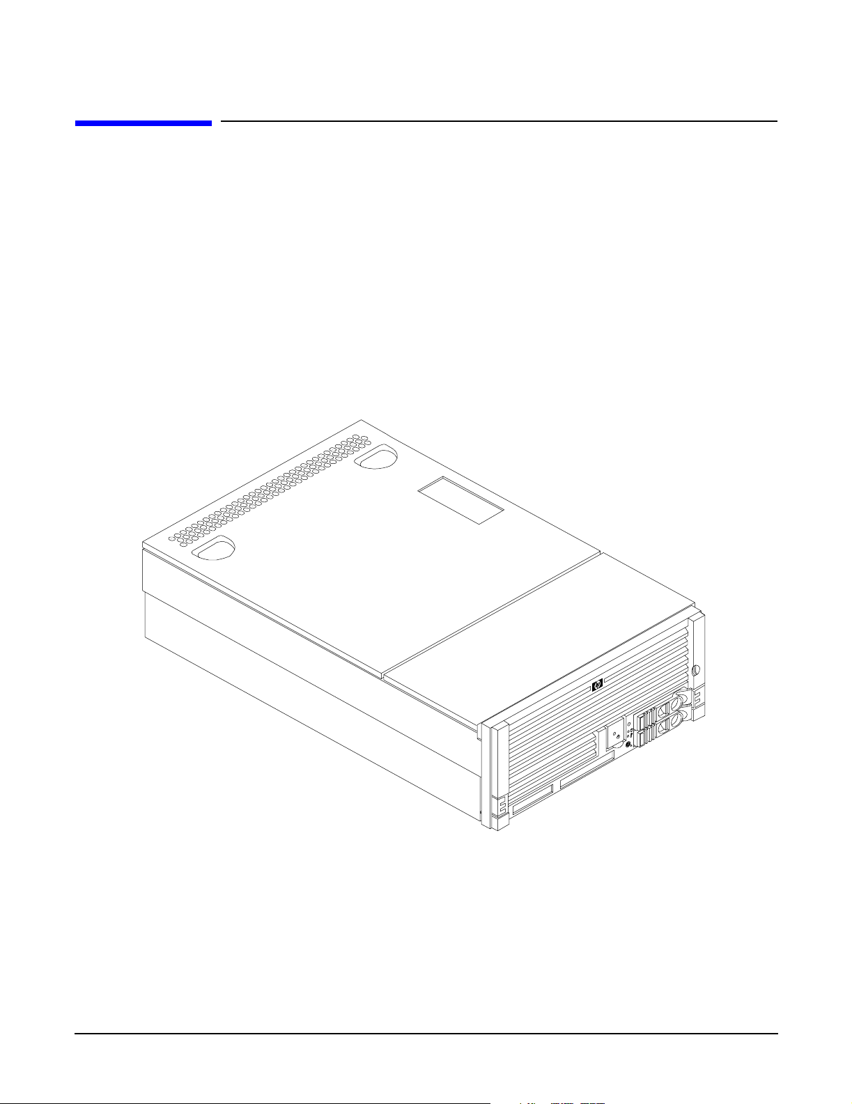
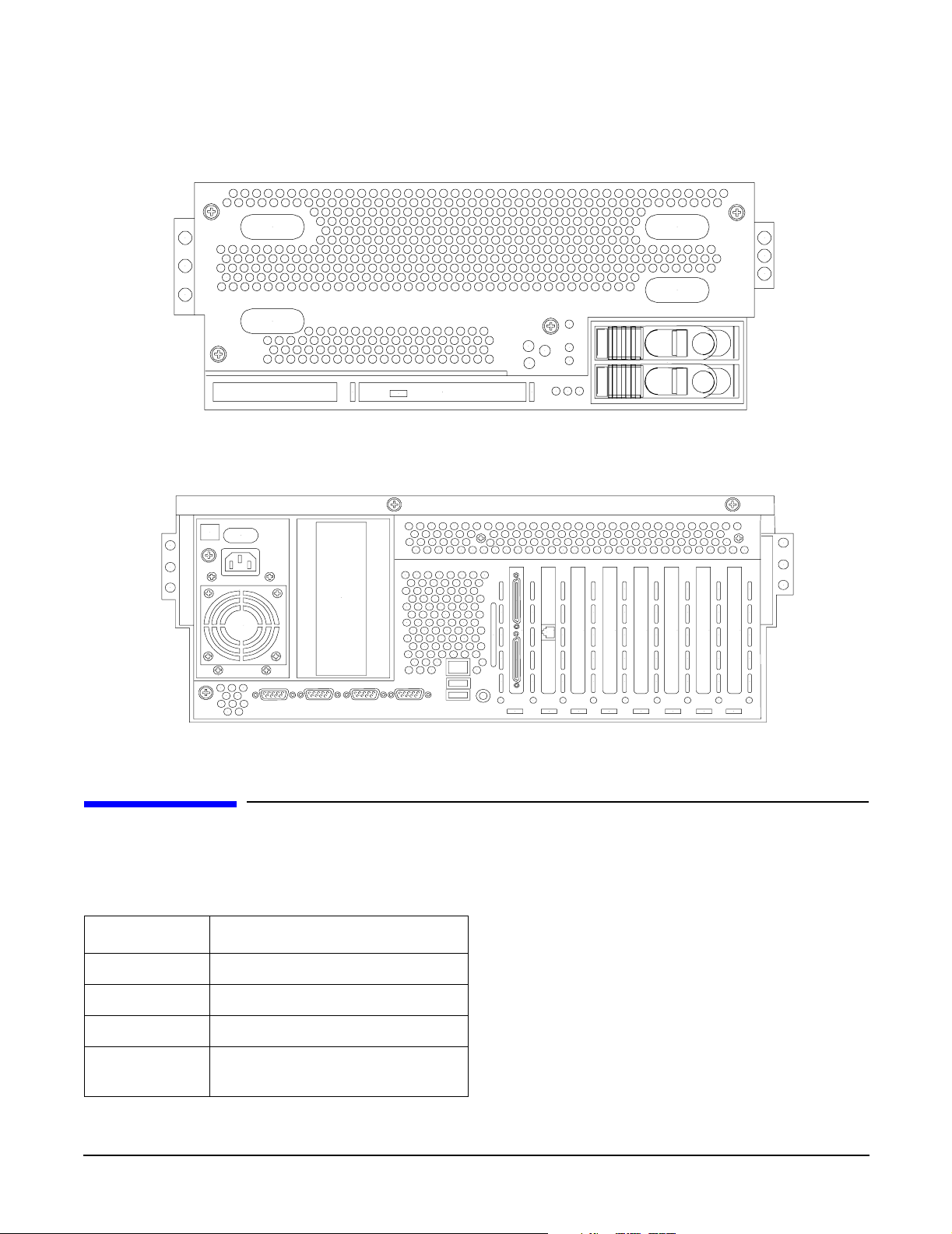
Figure 1-2, and Figure 1-3 show the top, front, and rear views of the server.
Figure 1-1 HP Integrity rx4640 Server with Front Bezel
20
Chapter 1
Page 21
Server Dimensions and Weight
Figure 1-2 HP Integrity rx4640 Server (front view with bezel removed)
Figure 1-3 HP Integrity rx4640 Server (rear view)
Introduction
Server Dimensions and Weight
Table 1-1 shows the dimensions and weight of the HP Integrity rx4640 server.
Table 1-1 Serv e r Dime ns ions
Dimensions Value
Height 17.46 cm (6.87 in.)
Width 44 cm (17.32 in.)
Depth (63.8 cm (25.1 in.)
Weight Unloaded - 40 kg (95 lb)
Fully loaded - 100 kg (220 lb)
Chapter 1
21
Page 22

Introduction
Server Components
Server Components
The following components comprise the HP Integrity rx4640 server.
Processors
The following processors are available for the rx4640 server:
• 1.6 GHz / 18 MB cache
• 1.6 GHz / 24 MB cache
These processors are dual core processors. The processor configuration options are 1-processor/2-core (1p/2c),
2p/4c, 3p/6c, or 4p/8c.
Memory
• 16 DIMM slots on standard memory extender board
• 32 DIMM slots on optional memory extender board
• Minimum memory size of 1 GB (four 256 MB DIMMs in
• Maximum memory size of 128 GB (4 GB DIMMs on 32-slot memory extender board)
• 256 MB, 512 MB, 1 GB, 2 GB, and 4 GB standard 184 pins 2.5V DDR 200, CL2, registered, ECC
• 200 MHz memory bus frequency, 400 MTransfers/s data, 12.8 GB/s peak data bandwidth
• DIMMs loaded by quads enable interleaved mode and chip spare
PCI Riser
• Two dedicated PCI slots (LAN and SCSI)
• Four hot-plug PCI-X 66 MHz, 64-bit, 3.3V, 25W slots with shared busses and I/O. Slots 3 and 4 share a
PCI-X bus and slots 5 and 6 share a PCI-X bus
• Two hot-plug PCI-X 133 MHz 64-bit 3.3V 25W slots
Internal Core I/O
• Dual channel SCSI U320 interface, two internal 68-pin connectors, two 68-pin external connectors
• The SCSI backplane is configured as either one or two channels
• One internal IDE connector for a slim-line optical device (CD and DVD)
• No floppy connector
External Core I/O
• Three external DB-9 ports (MP local, auxiliary, remote)
• Two external USB 2.0 ports
• Two SCSI Ultra320 68-pin connectors
22
Chapter 1
Page 23

• Two 10/100/1000Base-T ethernet LAN port
• One 10/100 integrated Lights Out Management Processor (iLO MP) LAN port
• One VGA port
Power Supply Unit
• 1200 W output power
• Redundant and hot-swap power supplies
Motherboard Manageability
• Baseboard Management Controller (BMC)
• Temperature monitoring and fans regulation by BMC
• Includes diagnostic panel LED display that shows server health
• Hardware diagnostics by BMC displayed by diagnostic panel LED
• IPMI protocol for communication between BMC/server/MP card
Introduction
Server Components
• Locator front/rear LEDs
• Field replacement units monitoring by BMC
Enhanced Server Manageability Using Management Processor
• LAN, telnet, and SSH console
•Web GUI
• Serial port for local console
• Serial port for modem console
• Duplication of console screen content across all consoles
Hard Disk Drives
• Two low-profile, hot-pluggable Ultra320 SCSI disk bays
• Disk options:
— 36 GB 15K RPM SCSI disk
— 73 GB 15K RPM SCSI disk
— 146 GB, 10K RPM SCSI disk
— 300 GB, 10K RPM SCSI disk
• Minimum server configuration includes one hard disk drive
Chapter 1
23
Page 24

Introduction
Supported Operating Systems
Supported Operating Systems
The following operating systems are supported on the entry-class HP Integrity servers:
• HP-UX 11i Version 2 (B.11.23)
• HP OpenVMS I64
• Microsoft® Windows® Server 2003
• Red Hat Enterprise Linux 4
• SuSE Linux Enterprise Server 10
For more operating system information, see Appendix B, “Booting the Operating System,” on page 139.
24
Chapter 1
Page 25

2 Controls, Ports, and LEDs
This chapter describes the controls, ports, and indicators found on the front panel, rear panel, and internal
locations of the HP Integrity rx4640 server.
This chapter addresses the following topics:
• “Front Panel Controls, Ports, and LEDs” on page 26.
• “Rear Panel Controls, Ports, and LEDs” on page 28.
• “Internal Controls, Ports, and LEDs” on page 31.
Chapter 2
25
Page 26
Controls, Ports, and LEDs
Front Panel Controls, Ports, and LEDs
Front Panel Controls, Ports, and LEDs
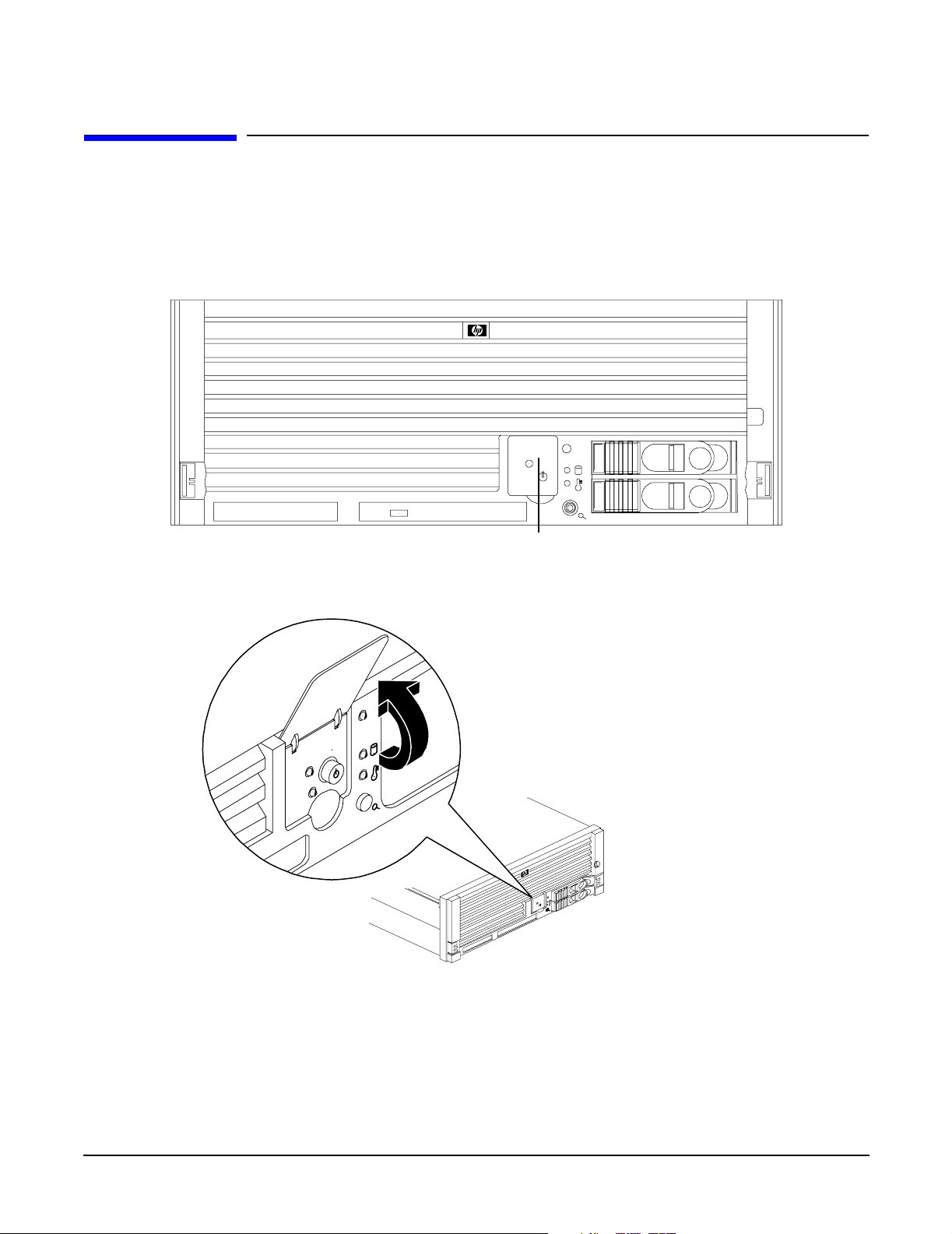
The front panel of the HP Integrity rx4640 server provides the controls and indicators commonly used for
operation. Figure 2-1, Figure 2-2, and Figure 2-3 show the controls, ports, and LEDs on the front panel and
control panel.
Figure 2-1 Front View with Bezel
Figure 2-2 Accessing the Control Panel
Control Panel
26
Chapter 2
Page 27
Controls, Ports, and LEDs
Front Panel Controls, Ports, and LEDs
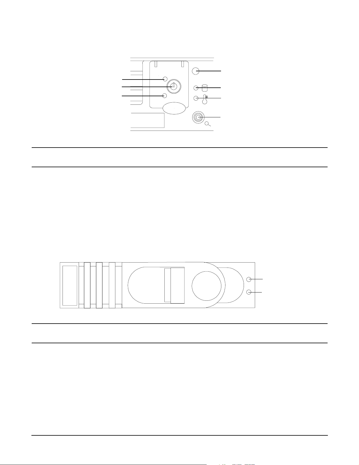
Figure 2-3 Control Panel LEDs
Server LED
Power LED
Power button
ToC/NMI button
NOTE For troubleshooting information regarding control panel LEDs, see “Front Control Panel LED
Indicators” on page 117.
Disk LED
Thermal LED
Locator
button/LED
Hard Disk Drive LED Indicators
The hot-swap disk drives have two LEDs per drive, as described below. Figure 2-4 shows the hard disk drive
LEDs.
• Status LED - The drive status LED displays green when disk power is on, and is off when disk power is
off.
• Activity LED - The drive activity LED is green and indicates disk drive activity. This LED is controlled by
the disk drive directly and turns on when a drive is accessed.
Figure 2-4 Hard Disk Drive LED Indicators
Status LED
Activity LED
NOTE For troubleshooting information regarding the hard disk drive LEDs, see “Hard Disk Drive
LED Indicators” on page 118.
Chapter 2
27
Page 28
Controls, Ports, and LEDs
Rear Panel Controls, Ports, and LEDs
DVD/DVD-R/DVD-RW Drives
The HP server is delivered with one DVD drive (DVD-R and DVD-RW optional). Each of these devices has one
activity LED. Figure 2-5 shows the location of the DVD LEDs.
Figure 2-5 DVD–ROM Drive
Eject Button Activity LED Emergency Eject
NOTE For troubleshooting information regarding the DVD LEDs, see “DVD/DVD-R/DVD-RW Drive
LED Indicators” on page 118.
Rear Panel Controls, Ports, and LEDs
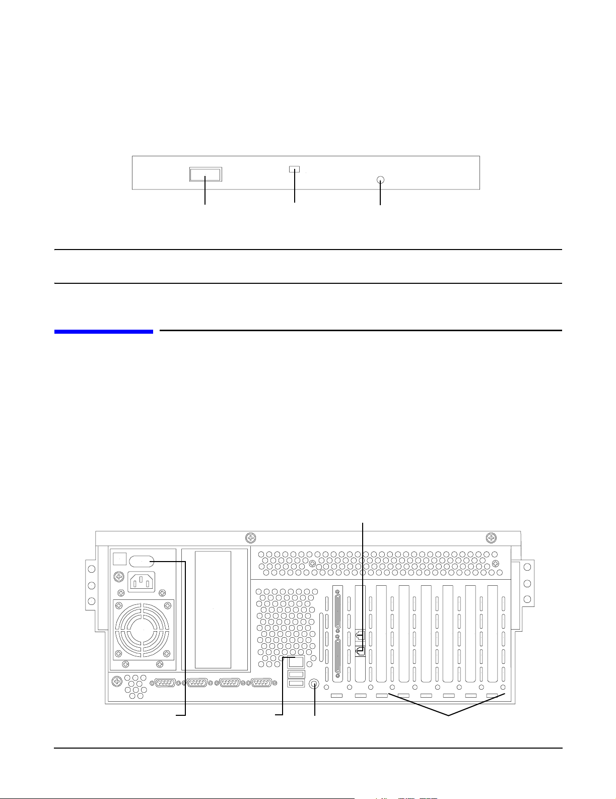
The HP server rear panel includes communication ports, I/O ports, AC power connectors, two power supply
bays, attention LED indicators for the hot-plug PCI boards, and the locator LED/button. Figure 2-6 shows the
LEDs located on the rear panel of the HP server. They include the:
• Power supplies
• Management Processor LAN
• 2 port Gigabit ethernet card LAN
• PCI slots 3-8
Figure 2-6 Rack Mount and Pedestal Rear View
Gigabit Ethernet LAN ports
Power supply LEDs
28
MP LAN LEDs
Locator button/LED
6 PCI attention LEDs
Chapter 2
Page 29
Controls, Ports, and LEDs
Rear Panel Controls, Ports, and LEDs
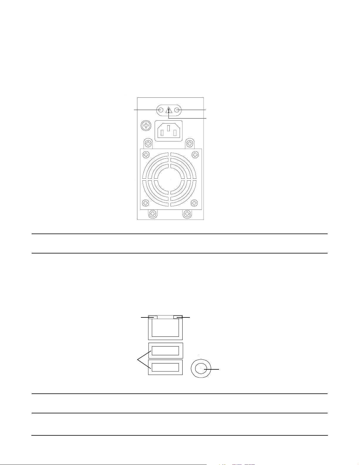
Power Supply Status LEDs
Each 200-240 VAC power supply unit has three status LEDs located on the power supply accessible from the
rear panel. Consolidated status of all power supplies is reported by the front control panel by the power status
LED. Figure 2-7 shows the location of the power supply status LEDs on the rear of the enclosure.
Figure 2-7 Power Supply Status LEDs
Predict fail
LED-amber
NOTE For troubleshooting information regarding the power supply status LEDs, see “Power Supply
Status LED Indicators” on page 123.
Power LED-green
Fail LED-amber
Management Processor LAN LEDs
The internal Management Processor (MP) LAN uses an RJ-45 type connector. This connector has two LEDs
(LAN link and LAN activity) that signal status and activity. Figure 2-8 shows the MP LAN LEDs and USB
ports on the rear panel of the server.
Figure 2-8 MP LAN LEDs
10M Link/Activity, Amber LED
USB Ports
NOTE For troubleshooting information regarding the iLO MP LAN LEDs, see “iLO MP LAN LED
Indicators” on page 124.
Chapter 2
100M Link/Activity, Green LED
Locator Button and LED
29
Page 30
Controls, Ports, and LEDs
Rear Panel Controls, Ports, and LEDs
Locator LED and Button
An LED and button is provided on the rear panel of the server. Another single blue LED and button is on the
front control panel that enables/disables the locator function. See Figure 2-8 for the location of the locator
button.
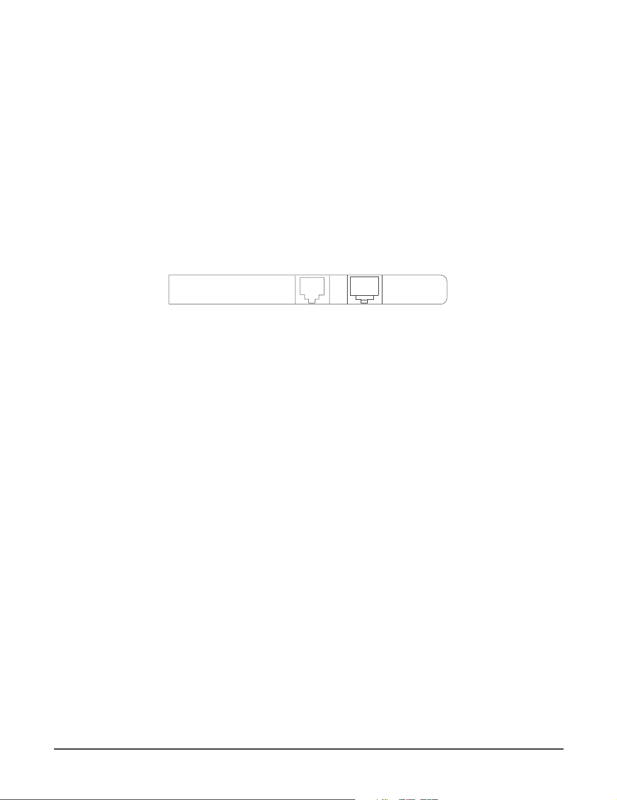
Gigabit Ethernet Card LAN Ports (Core I/O)
The 2-Port core I/O Gigabit ethernet card uses two RJ-45 LAN connectors. These connectors have no LEDs.
Figure 2-9 shows the two core I/O LAN ports.
Figure 2-9 Core I/O LAN Port LEDs
RJ-45 Connectors
30
Chapter 2
Page 31

Controls, Ports, and LEDs
Internal Controls, Ports, and LEDs
Internal Controls, Ports, and LEDs
The HP Integrity rx4640 server contains internal controls, switches, and LEDs inside the server. This
includes a diagnostic LED panel located under the top panel; and reset buttons, switches, and LEDs located
on the I/O baseboard.
QuickFind Diagnostic Panel
The QuickFind diagnostic panel has 58 single color LEDs and one multi-color LED for temperature. The
LEDs are normally off. The appropriate LED is turned on when an error is detected or a replacement part is
required. You can access the QuickFind diagnostic panel by removing the top cover. See “Removing the Top
Cover” on page 43. Figure 2-10 shows the QickFind diagnostic panel LEDs.
Figure 2-10 QuickFind Diagnostic Panel
NOTE For a complete description of QuickFind diagnostic LED states, see “QuickFind Diagnostic
Panel LED Indicators” on page 119.
Chapter 2
31
Page 32

Controls, Ports, and LEDs
Internal Controls, Ports, and LEDs
I/O Baseboard LED Indicators
There are various LEDs, sensors, reset, and attention buttons located on the HP Integrity rx4640 server I/O
baseboard. They are shown in Figure 2-11.
Figure 2-11 I/O Baseboard LEDs, Buttons, and Sensors
Battery
3.3VSB
power
LED
BMC
reset
button
5V VRM
LED
MP soft
reset
button
MP self-test
LED
MP heartbeat LED
BMC heartbeat LED
3.3V VRM LED
locator button/LED
12V VRM LED
PCI attention
LED
6X
PCI attention
button (doorbell)
6X
PCI power LED
6X
PCI attention LED
6X
NOTE For a complete description of the baseboard LEDs, see “I/O Baseboard LED Indicators” on
page 121.
32
Chapter 2
Page 33

3 Powering Off and Powering On the Server
This chapter provides information and procedures for powering off and powering on the server.
This chapter addresses the following topics:
• “Power States” on page 34.
• “Powering Off the Server” on page 34.
• “Powering On the Server” on page 35.
Chapter 3
33
Page 34

Powering Off and Powering On the Server
Power States
Power States
The server has three power states:
• Standby power
• Full power
•Off
Plug the power cord into the appropriate receptacle on the rear of the chassis to achieve the standby power
state; the front panel power button is not turned on. Full power occurs when the power cord is plugged into
the appropriate receptacle, and either the power is activated through the iLO MP PC command, or the power
button is activated. In the off state, the power cords are not plugged in. Table 3-1 lists the server power states.
Table 3-1 Powe r Stat e s
Power Cable
Power S tates
Standby power Yes No Yes No
Fu l l po wer Ye s Yes Yes Yes
Off No No No No
NOTE If the power restore feature is set to Always On through the iLO MP PR command, the server
automatically powers on to the full power state.
Plugged Into
Receptacle?
Power Activated through the
iLO MP PC Command; or
Front Panel Power Button
Activated?
AC Voltage
Applied
DC Voltage
Applied
Powering Off the Server
Power off the server using the following methods if the server is in either the standby or full power state:
•iLO MP PC command
• Power button
Powering Off the Server Using the iLO MP
To power off the server through the iLO MP, follow these steps:
Step 1. Gracefully shut down the operating system. See Appendix B, “Booting the Operating System,” on
page 139, or your operating system documentation for more information.
Step 2. Initiate a console session, and access the
Step 3. Enter CM to access the
34
Command Menu.
iLO MP Main Menu.
Chapter 3
Page 35

Powering Off and Powering On the Server
Powering On the Server
Step 4. Enter PC to use the remote power control command.
Step 5. Enter OFF to power off the server, and enter YES when prompted to confirm the action.
IMPORTANT The main DC voltage is now removed from the server; however, AC voltage for
standby power is still present in the server.
Step 6. Unplug all power cables from the receptacles on the rear panel of the server.
Powering Off the Server Manually
Manually power off the server through the power button by following these steps:
Step 1. Gracefully shut down the operating system. See Appendix B, “Booting the Operating System,” on
page 139, or your operating system documentation for more information.
Step 2. Press the power button to power off the server.
IMPORTANT The main DC voltage is now removed from the server; however, AC voltage for
standby power is still present in the server.
Step 3. Unplug all power cables from the receptacles on the rear panel of the server.
Powering On the Server
Power on the server to full power using the following methods if the server is in the standby power state:
•iLO MP PC command
• Power button
Powering On the Server Using the iLO MP
NOTE If the power restore feature is set to Always On through the iLO MP PR command, the server
may automatically power on to the full power state.
To power on the server through the iLO MP, follow these steps:
Step 1. Plug all power cables into the receptacles on the rear panel of the server.
Step 2. Initiate a console session, and access the iLO MP Main Menu.
Step 3. Enter CM. to enable command mode.
Step 4. Enter PC to use the remote power control command.
Step 5. Enter ON to power on the server, and enter YES when prompted to confirm the action.
Chapter 3
35
Page 36

Powering Off and Powering On the Server
Powering On the Server
Step 6. Start the operating system. See Appendix B, “Booting the Operating System,” on page 139, or your
operating system documentation for more information.
Powering On the Server Manually
NOTE If the power restore feature is set to Always On through the iLO MP PR command, the server
may automatically power on to the full power state.
To manually power on the server, follow these steps:
Step 1. Plug all power cables into the receptacles on the rear panel of the server.
Step 2. Press the power button to start the server.
Step 3. Start the operating system. See Appendix B, “Booting the Operating System,” on page 139, or your
operating system documentation for more information.
36
Chapter 3
Page 37

4 Removing and Replacing Components
This chapter describes the procedure for removing and replacing the different components in the HP Integrity
rx4640 server.
This chapter addresses the following topics:
• “Safety Information” on page 38
• “Service Tools Required” on page 38
• “Accessing a Rack Mounted Server” on page 38
• “Accessing a Pedestal Mounted Server” on page 40
• “Removing and Replacing the Front Bezel” on page 41
• “Removing and Replacing the Front and Top Covers” on page 42
• “Removing and Replacing the Memory Extender Board” on page 44
• “Removing and Replacing Server Memory DIMMs” on page 46
• “Removing and Replacing the Processor Extender Board” on page 52
• “Removing and Replacing a Processor” on page 55
• “Removing and Replacing Hot-Swap Chassis Fans” on page 63
• “Removing and Replacing the I/O Baseboard” on page 66
• “Removing and Replacing Hot-Plug PCI-X Cards” on page 71
• “Removing and Replacing OLX Dividers” on page 81
• “Removing and Replacing Core I/O Cards” on page 85
• “Removing and Replacing the Server Battery” on page 89
• “Removing and Replacing Hard Disk Drives” on page 90
• “Removing and Replacing the SCSI Backplane Board” on page 93
• “Removing and Replacing the Midplane Riser Board” on page 95
• “Removing and Replacing the Power Supplies” on page 98
• “Removing and Replacing the Power Distribution Board” on page 100
• “Removing and Replacing the DVD Drive” on page 102
• “Removing and Replacing the DVD I/O Board” on page 104
• “Removing and Replacing the Display Board” on page 107
• “Removing and Replacing the QuickFind Diagnostic Board” on page 109
Chapter 4
37
Page 38

Removing and Replacing Components
Safety Information
Safety Information
Follow the procedures listed below to ensure safe handling of components and to prevent harm to both you
and the HP server:
• Use an antistatic wrist strap and a grounding mat, such as those included in the Electrically Conductive
Field Service Grounding Kit (HP 9300-1155).
• Handle accessory boards and components by the edges only. Do not touch any metal-edge connectors or
any electrical components on accessory boards.
• Do not wear clothing subject to static charge build-up, such as wool or synthetic materials.
WAR NING Hazardous voltages are present inside the HP server. Always remove AC power
from the server and associated assemblies while working inside the unit. Serious
injury may result if this warning is not observed.
Service Tools Required
Service of this product may require one or more of the following tools:
• Electrically conductive field service kit (P/N 9300-1155)
• 1/4 inch flat blade screwdriver
• ACX-15 torx screwdriver
• ACX-25 torx screwdriver
Accessing a Rack Mounted Server
The HP Integrity rx4640 server is designed to be rack mounted. The following procedure explains how to gain
access to your HP Integrity rx4640 server that is mounted in an approved rack. For rack installation
instructions, review the document titled Installation Guide, Mid-Weight Slide Kit, 5065-7291. This document
can be accessed at: http://www.hp.com/racksolutions.
WAR NING Ensure that all anti-tip features (front and rear anti-tip feet installed; adequate
ballast properly placed; and so on) are employed prior to extending the server.
38
Chapter 4
Page 39

Removing and Replacing Components
Accessing a Rack Mounted Server
Extending the Server from the Rack
NOTE Ensure that there is enough area (Approximately 1.5 meters [4.5 ft.]) to fully extend the server
out the front and work on it.
To extend the server from the rack, perform the following steps:
Step 1. Remove the T-25 screws that fasten the server to the rack. See Figure 4-1, “Accessing 25MM Torx
Screws.”
Step 2. Flip out the two pull handles at either end of the front bezel and slowly pull the unit forward by the
handles. The server is fully extended when the rail clips are locked in place. When fully extended,
the front and top covers are fully accessible.
Figure 4-1 Accessing 25MM Torx Screws
25MM Torx
screw 2X
Inserting the Server into the Rack
To insert the server into the rack, perform the following steps:
Step 1. Press the rail clips on either side of the server inward and push the server into the rack until it
stops.
Step 2. Replace the T-25 screws that fasten the server to the rack.
Chapter 4
39
Page 40

Removing and Replacing Components
Accessing a Pedestal Mounted Server
Accessing a Pedestal Mounted Server
The HP Integrity rx4640 server is also designed to be pedestal mounted. You do not need to remove the
pedestal from the HP server to gain access to internal components. The front bezel, front cover, and top cover
may be removed with the pedestal attached to the HP server.
WAR NING Ensure that the HP server is properly grounded when performing
remove-and-replace procedures. Use an antistatic wrist strap and grounding mat
similar to those found in the HP Electrically Conductive Field Service Kit.
Figure 4-2 Pedestal Mounted HP Integrity rx4640 Server
40
Chapter 4
Page 41

Removing and Replacing Components
Removing and Replacing the Front Bezel
Removing and Replacing the Front Bezel
The server does not have to be turned off to remove the front bezel. Figure 4-3 shows how to remove the front
bezel.
Figure 4-3 Removing and Replacing the Front Bezel
Removing the Front Bezel
To remove the front bezel, perform the following step:
Step 1. Grasp the front bezel at the outer edges and pull straight out.
Replacing the Front Bezel
To replace the front bezel, perform the following step:
Step 1. Push the front bezel straight into the chassis until it snaps into place.
Chapter 4
41
Page 42

Removing and Replacing Components
Removing and Replacing the Front and Top Covers
Removing and Replacing the Front and Top Covers
The following procedures detail how to remove and replace the front and top covers of the HP Integrity
rx4640 server. Figure 4-4 shows how to remove the front cover.
NOTE When the front or top cover is removed the chassis fan units increase to high speed to assist
cooling. When the top cover is replaced at the end of the operation, the chassis fans return to
normal speed.
Figure 4-4 Removing and Replacing the Front Cover
Slots
Slots
Thumbscrews
Removing the Front Cover
To remove the front cover, perform the following steps:
Step 1. If rack mounted, slide the HP server out from the rack until it stops. See “Extending the Server
from the Rack” on page 39.
Step 2. Remove the front bezel. See “Removing the Front Bezel” on page 41.
Step 3. Using a torx T15 driver, loosen the four captive thumbscrews that hold the front cover in place.
Step 4. Raise the cover slightly, and pull the cover toward the front of the server to free the tabs from the
slots in the chassis.
42
Chapter 4
Page 43

Removing and Replacing Components
Removing and Replacing the Front and Top Covers
Replacing the Front Cover
To replace the front cover, perform the following steps:
Step 1. Align the tabs at the rear of the front cover with the corresponding slots in the chassis and fully
seat the tabs into the slots. Figure 4-4 shows how to install the front cover.
Step 2. Tighten the four thumbscrews securely.
Step 3. Replace the front bezel. See “Replacing the Front Bezel” on page 41.
Step 4. If rack mounted, slide the HP server into the rack until it stops. See “Inserting the Server into the
Rack” on page 39.
Removing the Top Cover
To remove the top cover, perform the following steps:
Step 1. If rack mounted, slide the HP server out from the rack until it stops. See “Extending the Server
from the Rack” on page 39.
Figure 4-5 Removing and Replacing the Top Cover
Thumbscrews
Step 2. Loosen the two captive thumbscrews that hold the top cover in place.
Step 3. Pull the cover toward the rear of the server to free the tabs from the slots in the chassis and lift it
straight up.
Chapter 4
43
Page 44

Removing and Replacing Components
Removing and Replacing the Memory Extender Board
Replacing the Top Cover
To replace the top cover, perform the following steps:
Step 1. Align the tabs at the rear of the top cover with the corresponding slots in the chassis, fully seat the
tabs into the slots, and push forward until it seats.
Step 2. Using a torx T15 driver, tighten the two thumbscrews securely.
Step 3. If rack mounted, slide the HP server into the rack until it stops. See “Inserting the Server into the
Rack” on page 39.
Removing and Replacing the Memory Extender Board
The memory extender board is located directly under the front cover of the chassis. The standard memory
extender board can hold up to 16 DIMMs. The high capacity memory extender board can hold up to 32
DIMMs.
WAR NING Ensure that the server is powered down and all power sources have been
disconnected from the server prior to removing or replacing a memory extender
board.
Voltages are present at various locations within the server whenever an AC power
source is connected. This voltage is present even when the main power switch is in
the off position.
Failure to observe this warning could result in personal injury or damage to
equipment.
CAUTION Observe all ESD safety precautions before attempting this procedure. Failure to follow ESD
safety precautions could result in damage to the server.
Removing the Memory Extender Board
To remove a memory extender board, perform the following steps:
Step 1. If rack mounted, slide the HP server out from the rack until it stops. See “Extending the Server
from the Rack” on page 39.
NOTE If desired, the memory extender board may be removed without removing the HP
server from the rack.
Step 2. Remove the front bezel from the chassis. See “Removing the Front Bezel” on page 41.
Step 3. Remove the front cover from the chassis. See “Removing the Front Cover” on page 42.
44
Chapter 4
Page 45

Removing and Replacing Components
Removing and Replacing the Memory Extender Board
Step 4. Press each latch on the two extraction levers located on each side of the memory extender board.
Figure 4-6 shows how to unlatch the memory extender board.
Figure 4-6 Opening the Memory Extender Board Latches
Step 5. Pull on the extraction levers to unplug the memory extender board from the socket located on the
midplane riser board and remove the memory extender board from the chassis. Figure 4-7 shows
how to remove the memory extender board from the server.
Figure 4-7 Removing and Replacing the Memory Extender Board
Chapter 4
45
Page 46

Removing and Replacing Components
Removing and Replacing Server Memory DIMMs
Replacing the Memory Extender Board
To replace the memory extender board, perform the following steps:
Step 1. Ensure the extraction levers are positioned in the outward, unlocked position. Figure 4-7 shows
how to install the memory extender board.
Step 2. Align the memory extender board with the front and rear chassis guide slots.
Step 3. Slide the memory extender board in until it begins to seat in the socket located on the midplane
board.
Step 4. Push the extraction levers inward to the locked position in order to plug in the memory extender
board into the midplane riser board.
Step 5. Replace the front cover. See “Replacing the Front Cover” on page 43.
Step 6. Replace the front bezel. See “Replacing the Front Bezel” on page 41.
Step 7. If rack mounted, slide the HP server into the rack until it stops. See “Inserting the Server into the
Rack” on page 39.
Removing and Replacing Server Memory DIMMs
Use these procedures to remove and replace server memory DIMMs. server memory DIMMs are located on
the memory extender board.
WAR NING Ensure that the server is powered down and all power sources have been
disconnected from the server prior to removing or replacing server memory DIMMs.
Voltages are present at various locations within the server whenever an AC power
source is connected. This voltage is present even when the main power switch is in
the off position.
Failure to observe this warning could result in personal injury or damage to
equipment.
CAUTION Observe all ESD safety precautions before attempting this procedure. Failure to follow ESD
safety precautions could result in damage to the server.
Removing Server Memory DIMMs
To remove server memory, perform the following steps:
Step 1. If rack mounted, slide the HP server out from the rack until it stops. See “Extending the Server
from the Rack” on page 39.
46
Chapter 4
Page 47

Removing and Replacing Components
Removing and Replacing Server Memory DIMMs
NOTE If desired, the processor extender board may be removed without removing the HP
server from the rack.
Step 2. Remove the front bezel. See “Removing the Front Bezel” on page 41.
Step 3. Remove the front cover. See “Removing the Front Cover” on page 42.
Step 4. Remove the memory extender board. See “Removing the Memory Extender Board” on page 44.
Step 5. Identify the DIMM to be removed and push the appropriate extraction levers found on either side of
the DIMM slot outward to the open position. The DIMM ejects from the slot.
Step 6. Remove the DIMM from the socket.
Installing Memory DIMMs
Your HP Integrity rx4640 comes with a 16 DIMM memory extender board that is minimally configured with
1GB of memory (four 256 Mb DIMMs loaded in quad 0 [slots 0A, 0B, 0C, and 0D]). See Figure 4-9 for the slot
locations on the 16 DIMM memory extender board.
An optional 32 DIMM memory extender board is available to replace the 16 DIMM memory extender board
and must also be minimally configured with 1 GB in quad 0. See Figure 4-10 for the slot locations on the 32
DIMM memory extender board.
You may insert additional DIMMs into both 16 and 32 DIMM boards. When adding DIMMs, you must use a
minimum of four like sized DIMMs in the next available quad. DIMMs must be loaded in quads with qualified
modules. Memory is protected by data ECC, and the hardware implementation supports chip-spare.
Supported DIMM Sizes
Supported DIMM sizes are 256 MB, 512 MB, 1 GB, 2 GB, or 4 GB. Dissimilar DIMM sizes may be used across
the entire extender board but all four DIMMs in each quad must match. For cooling purposes, DIMM fillers
must be used in some unused slots.
DIMM Slot Fillers
Both the 16 and 32 DIMM extender boards have DIMM slot filler boards placed over all unfilled DIMM slots.
As you fill DIMM quads with additional memory you must remove the DIMM slot fillers covering the affected
slots. All remaining DIMM fillers in unused slots must remain in place to maximize internal cooling. See
Table 4-2 and Table 4-4 for slot filler requirements for the 16 and 32 DIMM memory extender boards.
NOTE One DIMM filler board covers two adjacent DIMM slots. As a general rule, only remove DIMM
slot fillers as you add memory and the correct configuration will always remain.
Installing DIMMs
Perform the following steps to install DIMMs:
Step 1. Align the DIMM with the socket located on the memory extender board.
Step 2. Gently and evenly push on each side of the DIMM until it seats in the socket. Ensure that the
extraction levers are in the closed position. Repeat as needed until all additional DIMMs are
installed.
Step 3. Replace the memory extender board. See “Replacing the Memory Extender Board” on page 46.
Chapter 4
47
Page 48

Removing and Replacing Components
Removing and Replacing Server Memory DIMMs
Step 4. Replace the front cover. See “Replacing the Front Cover” on page 43.
Step 5. Replace the front bezel. See “Replacing the Front Bezel” on page 41.
Step 6. If rack mounted, slide the HP server into the rack until it stops. See “Inserting the Server into the
Rack” on page 39.
Figure 4-8 Inserting DIMM into Extender Board Slot
48
Chapter 4
Page 49

Removing and Replacing Components
Removing and Replacing Server Memory DIMMs
16 DIMM Memory Extender Board Layout
The following details the slot locations, quads, and slot filler requirements on the 16 DIMM memory extender
board.
Figure 4-9 shows the slot locations on the 16 DIMM extender board.
Figure 4-9 16 DIMM Extender Board Slot IDs
1D
1C
3C
3D
3A
3B
1B
1A
0D
0C
2C
2D
2A
2B
0B
0A
Table 4-1 details the quads on the 16 DIMM memory extender board.
Table 4-1 Quads on the 16 DIMM Memory Extender Board
Quad Slots
Quad 0 Slots 0A, 0B, 0C, 0D
Quad 1 Slots 1A, 1B, 1C, 1D
Quad 2 Slots 2A, 2B, 2C, 2D
Quad 3 Slots 3A, 3B, 3C, 3D
Chapter 4
49
Page 50
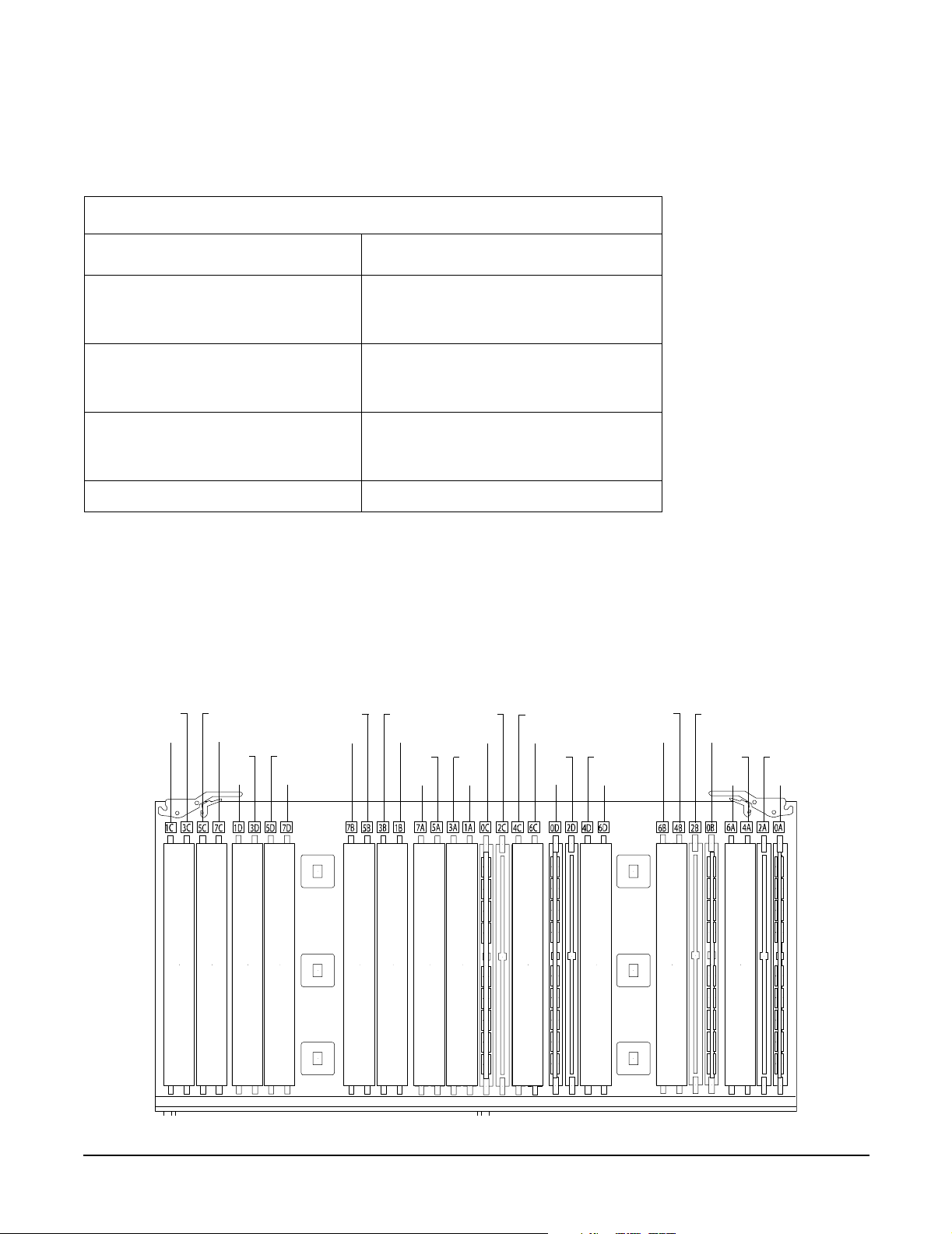
Removing and Replacing Components
Removing and Replacing Server Memory DIMMs
Table 4-2 details the slot filler requirements when installing DIMMs on the 16 DIMM memory extender
board.
Table 4-2 DIMM Filler Requirements for 16 DIMM Extender Board
16 DIMM Extender Board
DIMMs Loaded
4 DIMMs in quad 0 6 fillers total:
2 fillers in quads 1, 2, and 3
(all quads filled)
8 DIMMs in quads 0 and 1 4 fillers total:
2 fillers in quads 2 and 3
(all quads filled)
12 DIMMs in quads 0, 1, and 2 2 fillers total:
2 fillers in quads 3
(all quads filled)
16 DIMMs in quads 0, 1, 2, and 3 No fillers required
a. One DIMM filler board covers two adjacent DIMM slots.
Fillers Required
a
32 DIMM Memory Extender Board Layout
The following details the slot locations, quads, and slot filler requirements on the optional 32 DIMM memory
extender board.
Figure 4-10 shows the slot locations on the optional 32 DIMM extender board.
Figure 4-10 32 DIMM Extender Board Slot IDs
3C
1C
5C
7C
3D
1D
5D
7D
5B
7B
3B
1B
5A
7A
3A
1A
2C
0C
4C
6C
2D
0D
4D
6D
4B
6B
2B
0B
4A
6A
2A
0A
50
Chapter 4
Page 51

Removing and Replacing Components
Removing and Replacing Server Memory DIMMs
Table 4-3 details the quads on the 32 DIMM memory extender board.
Table 4-3 Quads on the Optional 32 DIMM Memory Extender Board
Quad Slots
Quad 0 Slots 0A, 0B, 0C, 0D
Quad 1 Slots 1A, 1B, 1C, 1D
Quad 2 Slots 2A, 2B, 2C, 2D
Quad 3 Slots 3A, 3B, 3C, 3D
Quad 4 Slots 4A, 4B, 4C, 4D
Quad 5 Slots 5A, 5B, 5C, 5D
Quad 6 Slots 6A, 6B, 6C, 6D
Quad 7 Slots 7A, 7B, 7C, 7D
Table 4-4 details the slot filler requirements when installing DIMMs on the optional 23 DIMM memory
extender board.
Table 4-4 DIMM Filler Requirements for 32 DIMM Extender Board
32 DIMM Extender Board
DIMMs Loaded
4 DIMMs in quad 0 12 fillers total:
2 fillers in quads 1, 3, 4, 5, 6, and 7
(quad 2 remains unfilled)
8 DIMMs in quads 0 and 1 8 fillers total:
2 fillers in quads 4, 5, 6, and 7
(quads 2 and 3 remain unfilled)
12 DIMMs in quads 0, 1, and 2 8 fillers total:
2 fillers in quads 4, 5, 6, and 7
(quad 3 remains unfilled)
16 DIMMs in quads 0, 1, 2, and 3 8 fillers total:
2 fillers in quads 4, 5, 6, and 7
(all quads filled)
20 DIMMs in quads 0, 1, 2, 3, and 4 4 fillers total:
2 fillers in quads 5, 7
quad 6 remains unfilled
24 DIMMs in quads 0, 1, 2, 3, 4, and 5 No fillers required
28 DIMMs in quads 0, 1, 2, 3, 4, 5, and 6 No fillers required
Fillers required
a
32 DIMMs in quads 0, 1, 2, 3, 4, 5, 6, and 7 No fillers required
a. One DIMM filler board covers two DIMM adjacent slots.
Chapter 4
51
Page 52

Removing and Replacing Components
Removing and Replacing the Processor Extender Board
Removing and Replacing the Processor Extender Board
The processor extender board is located directly under the memory extender board. The processor extender
board can hold between one and four processors.
WAR NING Ensure that the server is powered down and all power sources have been
disconnected from the server prior to removing or replacing the processor extender
board.
Voltages are present at various locations within the server whenever an AC power
source is connected. This voltage is present even when the main power switch is in
the off position.
Failure to observe this warning could result in personal injury or damage to
equipment.
CAUTION Failure to properly complete the steps in this procedure will result in erratic server behavior or
server failure. For assistance with this procedure contact your local HP Authorized Service
Provider.
Observe all ESD safety precautions before attempting this procedure. Failure to follow ESD
safety precautions could result in damage to the server.
Removing the Processor Extender Board
To remove the processor extender board, perform the following steps:
Step 1. If rack mounted, slide the HP server out from the rack until it stops. See “Extending the Server
from the Rack” on page 39.
NOTE If desired, the processor extender board may be removed without removing the HP
server from the rack.
Step 2. Remove the front bezel. See “Removing the Front Bezel” on page 41.
Step 3. Remove the front cover. See “Removing the Front Cover” on page 42.
52
Chapter 4
Page 53

Removing and Replacing Components
Removing and Replacing the Processor Extender Board
Step 4. Press the latch on the extraction levers located on each side of the processor extender board.
Figure 4-11 shows how to open the processor extender board latches.
Figure 4-11 Opening the Processor Extender Board Latches
Step 5. Pull out on the extraction levers to unplug the processor extender board from the socket located on
the midplane riser board. Figure 4-12 shows how to remove the extender board from the server.
Figure 4-12 Removing and Replacing the Processor Extender Board
Chapter 4
53
Page 54

Removing and Replacing Components
Removing and Replacing the Processor Extender Board
Replacing the Processor Extender Board
To replace the processor extender board, perform the following steps:
Step 1. Ensure the extraction levers are positioned in the outward, unlocked position.
Step 2. Align the processor extender board with the front and rear card guides.
Step 3. Slide the processor extender board down until it begins to seat in the socket located on the
midplane riser board.
Step 4. Push the extraction levers inward to the locked position in order to fully seat the processor
extender board into the socket on the midplane riser board.
Step 5. Replace the front cover. See “Replacing the Front Cover” on page 43.
Step 6. Replace the front bezel. See “Replacing the Front Bezel” on page 41.
Step 7. If rack mounted, slide the HP server into the rack until it stops. See “Inserting the Server into the
Rack” on page 39.
54
Chapter 4
Page 55

Removing and Replacing Components
Removing and Replacing a Processor
Removing and Replacing a Processor
Us the following procedures to remove and replace a processor on the processor extender board. Processors
are located on the top and bottom surfaces of the processor extender board.
WAR NING Ensure that the server is powered down and all power sources have been
disconnected from the server prior to removing or replacing a processor.
Voltages are present at various locations within the server whenever an AC power
source is connected. This voltage is present even when the main power switch is in
the off position.
Failure to observe this warning could result in personal injury or damage to
equipment.
Processor Load Order
Processor modules are housed on the processor extender board located under the top cover in the top service
bay. The processor extender board can hold between one and four processor modules. CPU 0 and CPU 1 are
located on the top of the processor extender board and CPU 2 and CPU 3 are located on the bottom.
Processors must be installed in a specific order as detailed in Table 4-5. Figure 4-13 shows the processor slot
locations on the processor extender board.
Table 4-5 Processor Load Order
Processor
Modules
First CPU 0
Second CPU 1
Third CPU 2
Fourth CPU 3
Socket
Chapter 4
55
Page 56

Removing and Replacing Components
Removing and Replacing a Processor
Figure 4-13 Processor Slot Locations on the Processor Extender Board
CPU 1
CPU 0
CPU 3 (under)
CPU 2 (under
CAUTION Do not modify the settings of the DIP switches located on the processor extender board. These
switches are for factory use only. Failure to observe this caution will result in server failure.
Removing a Processor
To remove a processor on the processor extender board, perform the following steps:
NOTE The processor being removed in this procedure is CPU 1. This procedure applies to all the
processors on the processor extender board.
Step 1. If rack mounted, slide the HP server out from the rack until it stops. See “Extending the Server
from the Rack” on page 39.
Step 2. Remove the front bezel. See “Removing the Front Bezel” on page 41.
Step 3. Remove the front cover. See “Removing the Front Cover” on page 42.
Step 4. Remove the processor extender board. See “Removing the Processor Extender Board” on page 52.
56
Chapter 4
Page 57

Removing and Replacing Components
Removing and Replacing a Processor
Step 5. Using a torx T15 driver, loosen the six captive T15 shoulder screws that attach the sequencer frame
on the heatsink in the order specified in Figure 4-14 until the sequencer frame is free.
Figure 4-14 Removing the Processor Sequencer
Sequencer
Shoulder
screws
5
3
1
4
6
2
Processor
power cable
Step 6. Remove the sequencer frame from the heatsink.
Step 7. Unplug the processor power cable from its socket on the extender board.
Chapter 4
57
Page 58

Removing and Replacing Components
Removing and Replacing a Processor
Step 8. Unlock the processor from the processor extender board by inserting the 2 mm hex end of the
processor installation tool through the processor into the ZIF socket lock and turning it 180 degrees
counterclockwise. Figure 4-15 shows the location of the ZIF socket lock.
Figure 4-15 Unlocking the Processor from the Processor Extender Board
Processor ZIF Socket Lock
Step 9. Carefully remove the processor from the processor extender board, and place in an antistatic bag.
Replacing a Processor
To install a processor on the extender board, perform the following steps. If you have already removed the
processor extender board from the server, proceed to step 6.
CAUTION Ensure that the cache size is identical for all processors. Failure to observe this caution will
result in server failure.
Ensure that all processors are rated for use at the same speed. Failure to observe this caution
will result in performance degradation.
Observe all ESD safety precautions before attempting this procedure. Failure to follow ESD
safety precautions could result in damage to the server.
58
Chapter 4
Page 59

Removing and Replacing Components
Removing and Replacing a Processor
Step 1. If rack mounted, slide the HP server out from the rack until it stops. See “Accessing a Rack
Mounted Server” on page 38.
Step 2. Remove the front bezel. See “Removing the Front Bezel” on page 41.
Step 3. Remove the front cover. See “Removing the Front Cover” on page 42.
Step 4. Remove the processor extender board. See “Removing the Processor Extender Board” on page 52.
Step 5. Using an antistatic wrist strap place the extender board on a grounding mat (Electrically
Conductive Field Service Grounding Kit-HP 9300-1155).
Step 6. Ensure the cam on the processor socket lock is in the unlocked, counterclockwise position.
Figure 4-16 shows the CPU 1 ZIF socket in the unlocked position.
Figure 4-16 CPU 1 Socket Unlocked
Alignment holes
Processor ZIF socket
lock in unlocked
position
Alignment holes
Step 7. Carefully lower the processor, without the sequencer clamp, onto the processor socket. Align the
pins on the bottom of the heatsink to the slots in the retention frame on the extender board.
Figure 4-16 shows the alignment holes on the processor extender board.
Chapter 4
59
Page 60

Removing and Replacing Components
Removing and Replacing a Processor
Step 8. Make sure the processor power cable is not pinched underneath the processor before locking the
processor onto the processor extender board. Figure 4-17 shows the correct placement of the
processor power cable.
Figure 4-17 Processor Cable Routed Correctly
Correct routing of CPU 1 power cable
CAUTION Test the alignment of the assembly to the socket by gently moving the assembly back
and forth with the palm of your hand—you should feel little or no sideplay. However,
because the assembly is not yet tightened, it may tilt slightly towards the center of
the extender board—this is acceptable.
CAUTION Before locking the processor assembly into its socket, ensure that the power cable is
not pinched between the heatsink and sheet metal frame of the extender board. See
Figure 4-17 for the correct placement of the processor power cable.
Step 9. Insert the 2 mm hex end of the processor installation tool through the processor into the ZIF socket
lock. Rotate the socket 180 degrees clockwise to lock the processor to the processor extender board.
CPU 1
60
Chapter 4
Page 61

Removing and Replacing Components
Removing and Replacing a Processor
CAUTION When rotating the locking cam, hold the palm of your hand on top of the assembly
and exert light pressure. This ensures that the assembly stays flush and level to the
socket while it is being tightened.
Figure 4-18 Locking the Processor to the Processor Extender Board
Processor ZIF Socket Lock
Step 10. Plug in the processor cable to its socket on the extender board.
Step 11. Place the sequencer frame over the processor.
Step 12. Using the ACX-15 torx screwdriver, tighten the six shoulder screws until they just bottom out.
Follow the tightening sequence shown in Figure 4-19.
Chapter 4
61
Page 62
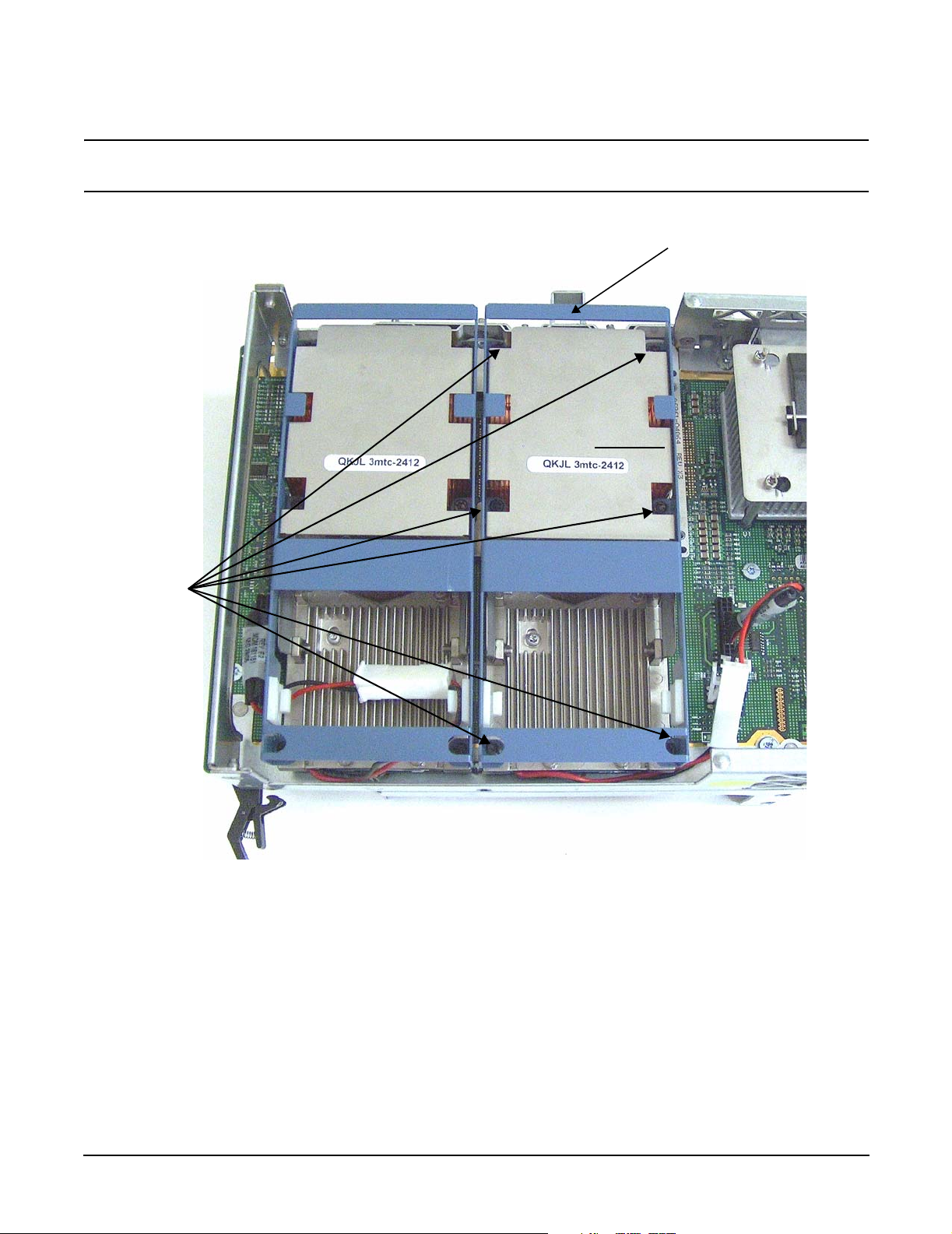
Removing and Replacing Components
Removing and Replacing a Processor
CAUTION Do not overtighten the six shoulder screws—they may shear off if overtightened.
Stop tightening the shoulder screws when you feel them just bottom out.
Figure 4-19 Installing Sequencer on Extender Board
Sequencer
Shoulder
screws
3
1
5
2
4
6
62
Chapter 4
Page 63

Removing and Replacing Components
Removing and Replacing Hot-Swap Chassis Fans
Removing and Replacing Hot-Swap Chassis Fans
There are three hot-swap chassis fan units in the HP server. Fan units 0, 1, and 2 are in the center of the
chassis, spanning the full chassis width. Fan units 0 and 1 are interchangeable and are in the left and center
positions. Fan unit 2 is smaller and only fits into the right-most position (behind the power supply).
CAUTION Observe all ESD safety precautions before attempting this procedure. Failure to follow ESD
safety precautions could result in damage to the server.
CAUTION When the server is running, the top cover must be replaced within two minutes to prevent
components from overheating. If the top metal cover is not replaced within five minutes, the
server automatically shuts down.
NOTE A hot-swap device does not require interaction with the operating system before the device is
removed from or installed into the server.
The AC power to the server does not have to be off to remove or replace a hot-swap chassis fan.
Removing a Hot-Swap Chassis Fan Unit
To remove a hot-swap chassis fan unit, perform the following steps:
Step 1. If rack mounted, slide the HP server out from the rack until it stops. See “Extending the Server
from the Rack” on page 39.
Step 2. Remove the top cover. See “Removing the Top Cover” on page 43.
Chapter 4
63
Page 64

Removing and Replacing Components
Removing and Replacing Hot-Swap Chassis Fans
Step 3. Grasp the fan unit locking handle, tilt it up, and pull out the fan from the chassis.
Figure 4-20 Removing and Replacing the Chassis Fans 0 and 1
64
NOTE When one fan unit is removed from the server, the remaining fan units operate at
full speed for two minutes. After two minutes the server goes into soft-shutdown
mode.
Chapter 4
Page 65

Removing and Replacing Hot-Swap Chassis Fans
Figure 4-21 Removing and Replacing the Chassis Fan 2
Removing and Replacing Components
Replacing a Hot-Swap Chassis Fan Unit
To replace a hot-swap chassis fan unit, perform the following steps:
Step 1. Orient the fan units by aligning the appropriate icon on the fan unit handle to the identical icon on
the chassis wall. Fan units 0 and 1 have “triangle” icons and fan unit 2 has a “square” icon.
Step 2. Push the fan unit firmly into the housing and close the handle until flush to the top of the
chassis—the fan unit plugs into the power outlet on the I/O baseboard.
CAUTION If the fan unit handle does not close completely, it is misaligned. Remove the fan unit
and check that the alignment icons are oriented correctly.
Chapter 4
65
Page 66

Removing and Replacing Components
Removing and Replacing the I/O Baseboard
Step 3. Check the QuickFind diagnostic board LED indicating the replaced fan unit.
• When the fan is functioning normally, the LED is off.
• When the fan fails, the LED is lit.
Step 4. Replace the top cover. “Replacing the Top Cover” on page 44.
Step 5. If rack mounted, slide the HP server into the rack until it stops. “Inserting the Server into the
Rack” on page 39.
Removing and Replacing the I/O Baseboard
These procedures detail how to remove the I/O baseboard from the server. The I/O baseboard is removed from
the rear of the server.
WAR NING Ensure that the server is powered down and all power sources have been
disconnected from the server prior to removing or replacing the I/O baseboard
assembly.
Voltages are present at various locations within the server whenever an AC power
source is connected. This voltage is present even when the main power switch is in
the off position.
Failure to observe this warning could result in personal injury or damage to
equipment.
CAUTION Failure to properly complete the steps in this procedure results in erratic server behavior or
server failure. For assistance with this procedure contact your local HP Authorized Service
Provider.
Observe all ESD safety precautions before attempting this procedure. Failure to follow ESD
safety precautions could result in damage to the server.
Removing the I/O Baseboard
To remove the I/O baseboard, perform the following steps:
Step 1. If rack mounted, slide the HP server out from the rack until it stops. See “Extending the Server
from the Rack” on page 39.
Step 2. Remove the top cover. See “Removing the Top Cover” on page 43.
Step 3. Remove the three chassis fan units. See “Removing a Hot-Swap Chassis Fan Unit” on page 63.
Step 4. Unplug all external cabling attached to ports at the rear of the I/O baseboard.
Step 5. Unplug the SCSI cables attached to the HBA board in PCI slot 1.
66
Chapter 4
Page 67

Removing and Replacing Components
Removing and Replacing the I/O Baseboard
CAUTION When unplugging the SCSI cables, note the labeling on the SCSI A and SCSI B
channel cables. When plugging in these cables, you must match each cable with its
appropriate socket on the SCSI HBA. If the cables are mismatched your server may
not reboot. Both cables and sockets are clearly marked with the correct channel.
Step 6. Lift up on the locking lever attached to the side of the Power Supply cage to unplug the I/O
baseboard from the socket on the midplane riser board. Figure 4-22 shows the locking lever.
Figure 4-22 I/O Baseboard Locking Lever
OPEN
CLOSE
Chapter 4
67
Page 68

Removing and Replacing Components
Removing and Replacing the I/O Baseboard
Step 7. Grasp the handle on the rear of the server and slide the I/O baseboard assembly all the way to the
rear until removed from chassis. Figure 4-23 shows how to remove the I/O baseboard.
NOTE The I/O baseboard assembly is large, so be careful when lifting it out of the server.
Figure 4-23 Removing the I/O Baseboard
68
Chapter 4
Page 69

Replacing the I/O Baseboard
To replace the I/O baseboard, perform the following steps:
Step 1. Set the I/O baseboard switches as shown in Figure 4-24.
Figure 4-24 I/O Baseboard Switches
I/O baseboard switches
Removing and Replacing Components
Removing and Replacing the I/O Baseboard
NOTE The I/O baseboard is large, so use care when sliding it into the server chassis.
Step 2. Align the I/O baseboard assembly rails with the chassis slots and slide the assembly into the
chassis until it stops against the midplane riser board socket.
CAUTION Ensure the I/O baseboard locking lever is in the “up” position or the I/O baseboard
hangs up before engaging the midplane riser board socket.
Step 3. With the I/O baseboard flush against the midplane riser board socket, push down firmly on the
locking lever until the I/O baseboard plugs all the way into the midplane riser board socket.
Step 4. Replace the three chassis fan units. “Replacing a Hot-Swap Chassis Fan Unit” on page 65.
Step 5. Plug in all external cabling the rear ports of the I/O baseboard.
Chapter 4
69
Page 70

Removing and Replacing Components
Removing and Replacing the I/O Baseboard
CAUTION When plugging the SCSI cables, note the labeling on the SCSI A and SCSI B channel
cables. You must match each cable with its appropriate socket on the SCSI HBA. If
the cables are mismatched your server may not reboot. Both cables and sockets are
clearly marked with the correct channel.
Step 6. Plug in the internal SCSI cable(s) to the HBA board in PCI slot 1.
Step 7. Replace the top cover. See “Replacing the Top Cover” on page 44
Step 8. If rack mounted, slide the HP server into the rack until it stops. See “Inserting the Server into the
Rack” on page 39.
Step 9. Power up and boot to EFI.
Step 10. Respond YES to prompts regarding copying information onto the new I/O baseboard.
Step 11. Enter SERVICE mode.
Shell> sysmode service
Current System Mode: ADMIN
You are now in SERVICE mode.
Step 12. Use the 'sysset' command to enter the product data:
Shell> sysset prodname "server rx4640"
Step 13. Use the sysset command to verify all values are set:
Shell> sysset
System Information:
Manufacturer: hp
Product Name: server rx4640
Product Number: A6961A
Secondary Product Number is Identical
Serial number: SGH43442VB
Secondary Serial Number is Identical
UUID: 3C33C58E-2E5A-11D8-A33B-4188C0AEFAE2 (Valid)
Secondary UUID is Identical
Product ID: 0x305
Step 14. Use the EFI date and time commands to set the correct local date and time.
Step 15. Boot the server and resume normal operation.
70
Chapter 4
Page 71

Removing and Replacing Components
Removing and Replacing Hot-Plug PCI-X Cards
Removing and Replacing Hot-Plug PCI-X Cards
The HP Integrity rx4640 server supports PCI-X hot-plug technology and offers six PCI-X, hot-plug capable
slots.
CAUTION There are restrictions on the number of PCI-X cards that can be installed in the rx4640 server
at any given time, depending on the cards being used.
Maximum quantity for any I/O configuration using 337972-B21, AB287A, or A9890A cards:
• Three 337972-B21 cards maximum plus three unpopulated slots
• Two AB287A cards maximum plus four unpopulated slots
• Three A9890A cards maximum plus three unpopulated slots
Failure to observe this caution will result in server degradation, or server failure.
PCI-X Specifications
PCI-X technology enables the following hot-plug operations. For procedures with step-by-step instructions
describing how to add, replace, delete, and locate PCI-X cards see “Hot-Plug Operation Procedures” on
page 77.
• Online Addition (OL-A)
You can install new PCI-X expansion cards in previously empty slots without powering down the server.
• Online Replacement (OL-R)
You can replace a previously occupied slot with a new PCI-X expansion card by suspending the driver.
This operation combines removing an active card and replacing it with an equivalent capability card. The
existing driver for the old card must be compatible with the new card.
CAUTION A special OL-R requirement for HP-UX 11i v2 is that the card to be inserted (replaced)
must be exactly the same as the removed card. This is also known as like-for-like
replacement.
NOTE Windows Server 2003 Enterprise Edition does not support OL-R. Instead, you can do a
combination of an OL-D operation followed by an OL-A operation. This is the equivalent of
an OL-R operation.
• Online Deletion (OL-D)
You can remove an existing PCI-X expansion card. This operation is different from OL-R because there
are no restrictions placed on the type of replacement card that you can use. In this operation, the drivers
are also completely removed from the slot.
NOTE HP-UX 11i v2 does not support OL-D. It does support OL-R.
• PCI-X Slot Locate (Locate)
Chapter 4
71
Page 72

Removing and Replacing Components
Removing and Replacing Hot-Plug PCI-X Cards
To easily locate the PCI-X slot at which you wish to perform a hot-plug operation, you can command the
attention LEDs, on the OLX divider and the I/O baseboard, to blink and act as visual cues to the active slot
location. This operation is always initiated through a software or web interface and is optional to the
operating system on your HP server.
Operating System Support for Hot-Plug PCI-X Operations
The capability of each operating system to support hot-plug PCI-X operations is different. The following
explanation details the capabilities of each operating system.
NOTE Open VMS does not support hot-plug PCI-X operations.
• HP-UX 11i v2
HP-UX 11i v2 supports only OL-A, OL-R, and Locate hot-plug PCI-X operations.
In OL-R, it is a requirement that the card to be inserted (replaced) be exactly the same as the card being
removed. During this OL-R operation, HP-UX 11i v2 suspends the device driver and re-enables it upon
completion of the OL-R operation.
In HP-UX 11i v2, the Locate function is only available through the command line or web interface.
• Windows Server 2003 Enterprise Edition
Windows Server 2003 Enterprise Edition supports only OL-A and OL-D hot-plug PCI-X operations.
In OL-D, Windows Server 2003 Enterprise Edition will delete the device object, after the card’s successful
removal from the slot. You do not have to re-install drivers for the deleted device on subsequent insertions
or reboots
To perform a card replacement hot-plug PCI-X operation in Windows Server 2003, you must first perform
an OL-D operation followed by an OL-A operation.
• Linux Red Hat Advanced Server 2.1
At this time Linux RHEL4 U3 does not support hot-plug PCI-X technology.
Table 4-6 shows hot-plug operations that are available in HP-UX 11i v2, Windows Server 2003 Enterprise
Edition, and Linux Red Hat Advanced Server 2.1 operating systems.
Table 4-6 Hot-Plug Operation and OS Compatibility
Linux Red Hat
Hot-Plug
Operation
OL-A Yes Yes No
OL-R Yes. HP-UX 11i v2 demands
like-for-like replacement. A like-for-like
card means that the new card is exactly
the same as the card being replaced.
HP-UX 11i v2
Windows Server 2003
Enterprise Edition
No. But, you can perform a
combination of OL-D and
OL-A to replace a card.
Enterprise
Advanced Server
4 Update 3
No
OL-D Not supported by HP-UX 11i v2. Yes No
72
Chapter 4
Page 73

Removing and Replacing Components
Removing and Replacing Hot-Plug PCI-X Cards
Table 4-6 Hot-Plug Operation and OS Compatibility (Continued)
Hot-Plug
Operation
HP-UX 11i v2
Windows Server 2003
Enterprise Edition
Linux Red Hat
Enterprise
Advanced Server
4 Update 3
Locate Yes. Only supported through the
command line interface or the web
interface.
No No
PCI-X Hardware and Software Interfaces
Table 4-7 shows what hot-plug hardware and software interfaces are available on HP-UX 11i v2, Windows
Server 2003 Enterprise Edition, and Linux Red Hat Advanced Server 2.1 operating systems.
Table 4-7 Hot-Plug Hardware and Software Interfaces and OS Availability
Windows Server
Hot-Plug PCI-X Interface HP-UX 11i v2
Hardware interface comprised of:
—Attention Button
—Manual Retention Latch
—Power LED
—Attention LED
—PCI-X card lock
Graphical User Interface Yes Yes. You can use the
Yes Yes No
2003 Enterprise
Edition
Safely Remove
Hardware icon in
the tool tray or
device manager to
remove a device
(OL-D).
OL-A is only
possible through the
hardware interface.
Linux Red Hat
Enterprise
Advanced Server
4 Update 3
No
Command Line Interface (CLI) Yes -olrad command.
Read Interface Card OL*
Support for HP-UX Servers
and Workstations, olrad
Command Line Interface
at http://docs.hp.com.
Chapter 4
No No
73
Page 74

Removing and Replacing Components
Removing and Replacing Hot-Plug PCI-X Cards
Table 4-7 Hot-Plug Hardware and Software Interfaces and OS Availability
Linux Red Hat
Enterprise
Advanced Server
4 Update 3
Hot-Plug PCI-X Interface HP-UX 11i v2
Web Interface Yes- pdweb command.
Read Interface Card OL*
Support for HP-UX Servers
and Workstations,
pdweb-Peripheral Device
tool Web Interface, at
http://docs.hp.com.
Windows Server
2003 Enterprise
Edition
No No
PCI-X Slot Locations and Configurations
PCI-X slots are numbered from 1 through 8 in your HP server. Figure 4-25 shows the slot locations on the I/O
baseboard.
The following describes configuration requirements for slots 1 through 8 (see Table 4-8 for configuration
requirements):
• PCI slots 1 and 2 are dedicated for use by the core I/O cards—SCSI HBA card in slot 1 and Gigabit
Ethernet LAN card in slot 2. Slots 1 and 2 are not hot-plug capable. Additional PCI-X expansion cards
may not be placed in slots 1 or 2.
• Slots 3 and 4 share a PCI-X bus, and slots 5 and 6 share a PCI-X bus. The maximum capability of each
slot sharing a PCI-X bus is PCI-X 66 MHz. If a PCI-X 133 MHz card is placed in a slot sharing a bus, the
maximum capability the PCI-X 133 MHz card can run at is PCI-X 66 MHz. If different modes (PCI vs.
PCI-X) or slower speeds (33 MHz) are used, then the slot automatically downgrades to accept the change.
Shared slots have card compatibility restrictions. If one of the shared slots is occupied then the card being
added to the second slot is limited by the configuration of the occupied slot. If the new card has a slower
capability than the current bus configuration, it will be rejected. If the new card has a faster capability
than the current bus configuration, it will only run at the bus mode and frequency of the current bus
configuration (slower).
1. If you have a 66 MHz card in slot 3, and you hot-plug insert a 33 Mhz card into slot 4, then the
operation will not succeed. The new 33 MHz card will not initialize and the slot will power down
because you cannot change bus speed during hot-plug operations.
NOTE If the server is rebooted in the new configuration, then both cards re-initialize to run at
33 MHz. This is because the server firmware can only change the bus capability from
66 MHz down to 33 MHz.
2. If you have a 33 MHz card in slot 3, and you hot-plug insert a 66 Mhz card into slot 4, it will work but
the new card will run at 33 MHz. This also applies to slots 5 and 6, as they are shared (both use a
common bus).
3. If your unit is powered down and you insert a 33 MHz card into slot 4 (that shares a 66 MHz card in
slot 3), then both cards will run at 33 MHz when the unit is powered up. This also applies to slots 5
and 6, as they are shared (both use a common bus).
74
Chapter 4
Page 75

Removing and Replacing Components
Removing and Replacing Hot-Plug PCI-X Cards
• Slots 7 and 8 are single slots, they do not share a PCI-X bus. The maximum capability of each slot is
PCI-X 133 MHz. Only slots 7 and 8 allow 133 Mhz, PCI-X cards to run at full speed. These two slots are
not limited by bus mode frequency related incompatibilities.
Table 4-8 PCI-X Card vs. Slot Frequency/Bus Mode Compatibility for Shared
a
Slots
Current PCI Bus
Mode and
Frequency for
the Shared Slot
PCI 33 MHz
PCI 33 PCI 66 PCI-X 66 PCI-X 133
Compatible
PCI 66 MHz Incompatible
-Frequency
c
PCI-X 66 MHz Incompatible
-Frequency
(note c)
e
PCI-X 133 MHz
Incompatible
-Frequency
(note c)
b
Compatible
(note b)
New card
running at
PCI 33
Compatible
(note b)
IncompatibleBus
IncompatibleFrequency
(note c)
Cards to be installed
Compatible
(note b)
New card
running at
PCI 33
Compatible
(note b)
New card
running at
PCI 66
Compatible
d
(note b)
Compatible
(note b)
New card
Compatible
(note b)
New card
running at
PCI 33
Compatible
(note b)
New card
running at
PCI 66
Compatible
(note b)
New card
running at
PCI-X 66
Compatible
(note b)
New card
running at
PCI-X 66
a. The conditions described in this table apply only to shared slots (slots 3,4-bus
2 and 5,6-bus 3). Slots 7 and 8 are not shared slots.
b. Compatible: card is accepted and runs at frequency shown.
c. Incompatible-Frequency: card is rejected. The new card will not initialized and
will power down due to frequency mismatch.
d. Incompatible-Bus: Card is rejected. The new card will not initialize and will
power down due to bus mode mismatch.
e. Maximum bus mode and frequency supported on shared slots is PCI-X 66
MHz.
CAUTION If you are using Linux Red Hat Enterprise Advanced Server 4 Update 3 operating system and
you want to install a 1000b-Sx GigE card, do not install it into a slot that shares a bus with a 33
MHz card. In this configuration the Linux driver will not initialize the new card.
Chapter 4
75
Page 76

Removing and Replacing Components
Removing and Replacing Hot-Plug PCI-X Cards
CAUTION Do not use more than 3 RAID cards in any of the slots on your HP Integrity rx4640 server.
Server power limitations restrict the use of more than 3 RAID cards per server.
Figure 4-25 Slot ID Numbering
PCI-X Bus 1
PCI-X Bus 2
PCI-X Bus 3
PCI-X Bus 4
PCI-X Bus 5
1 23456 78
Core I/O
PCI-X
Public I/O
PCI-X, Hot-Plug
Slot ID Number
Amber attention LEDs, 6x
Green power LEDs, 6x
Amber attention LEDs, 6x
76
Chapter 4
Page 77

Removing and Replacing Components
Removing and Replacing Hot-Plug PCI-X Cards
Hot-Plug Operation Procedures
The hot-plug procedures described in this section will use the hardware interface only. Software interface
procedures are described in Table 4-7, “Hot-Plug Hardware and Software Interfaces and OS Availability.” For
a complete understanding of all HP-UX 11i v2 hot-plug techniques and concepts, it is recommended that you
refer to Interface Card OL* Support for HP-UX Servers and Workstations at http://docs.hp.com.
CAUTION Before adding or replacing a PCI-X card, determine if that card is critical to your servers
operation. If you replace a card that is still operating and it is a critical resource to your server,
you may cause undesired server downtime. Read Interface Card OL* Support for HP-UX
Servers and Workstations, Critical Resources at http://docs.hp.com, prior to performing a
hot-plug operation.
Online Addition-(OL-A)
Before installing a PCI-X card, ensure that the proper drivers for that PCI-X card are installed.
To add a PCI-X card into an empty slot, perform the following steps:
Step 1. If rack mounted, slide the HP server out from the rack until it stops. See “Extending the Server
from the Rack” on page 39.
Step 2. Remove the top cover from the chassis. See “Removing the Top Cover” on page 43.
Step 3. If the power LED is steady-on (power to slot is on), go to step 4. If the power LED is steady-off
(power to slot is off), go to step 5.
Step 4. To turn off power to the slot, pull up on the manual retention latch (MRL) located on the OLX
divider. The power LED goes to steady-off. Figure 4-26 shows the layout of the card divider.
CAUTION Do not pull up on the MRL of a powered-on, occupied slot or your server will crash.
This OL-A procedure is for powering down a powered-on, unoccupied slot only. For a
detailed procedure on how to power down an occupied slot see “Online
Replacement-(OL-R)” or “Online Deletion (OL-D)”.
Step 5. Ensure that the MRL is already open and insert the PCI-X card to be added into the powered down
slot. Figure 4-27 shows how to correctly install a PCI-X card.
CAUTION When inserting the PCI-X card, be careful you do not accidentally touch an attention
button on the other OLX dividers—this will initiate an undesired shutdown of
another PCI-X card/slot.
Also, ensure that you fully seat the card into the slot or undesired results may occur
after power is re-applied to the slot.
Step 6. Push the manual retention latch down until it seats against the chassis wall.
Step 7. Turn the PCI-X card lock to the closed position to capture the PCI-X card and manual retention
latch into the closed position.
Step 8. Press the attention button and the power LED starts to blink. Wait until the power LED goes from
blinking to steady-on.
Chapter 4
77
Page 78

Removing and Replacing Components
Removing and Replacing Hot-Plug PCI-X Cards
NOTE After pushing the attention button, you have 5 seconds to cancel the operation by
pushing the attention button again.
Step 9. Replace the top cover.
Step 10. Push the HP server all the way back into the rack until it stops.
Figure 4-26 PCI-X OLX Divider Layout
PCI-X card latch
closed position
Manual retention
latch—closed
PCI-X card latch
open position
Manual retention
latch—open
Power LED
light pipe
Attention button
Attention LED
light pipe
78
Chapter 4
Page 79

Figure 4-27 Inserting PCI-X Card
Removing and Replacing Components
Removing and Replacing Hot-Plug PCI-X Cards
Online Deletion (OL-D)
To delete a PCI-X card from an occupied slot, perform the following steps:
Step 1. If rack mounted, slide the HP server out from the rack until it stops. See “Extending the Server
from the Rack” on page 39.
Step 2. Remove the top cover from the chassis. See “Removing the Top Cover” on page 43.
Step 3. Press the attention button located on the OLX divider that controls the affected slot—the power
LED starts to blink. Wait until the power LED goes from blinking to steady-off.
NOTE After pushing the attention button, you have 5 seconds to cancel the operation by
pushing the attention button again.
Chapter 4
79
Page 80

Removing and Replacing Components
Removing and Replacing Hot-Plug PCI-X Cards
Step 4. Turn the PCI-X card lock on the chassis until the manual retention latch (MRL) is free to pull up.
Step 5. At this point, the power to the slot is off; pull up on the manual retention latch located on the OLX
divider. Figure 4-26 shows the layout of the PCI-X card divider.
Step 6. Remove the existing PCI-X card from the slot.
Step 7. Push the manual retention latch down until it seats against the chassis wall.
Step 8. Replace the top cover. See“Replacing the Top Cover” on page 44.
Step 9. Push the HP server all the way back into the rack until it stops. See “Inserting the Server into the
Rack” on page 39.
Online Replacement-(OL-R)
As discussed earlier, OL-R is a combination of an OL-D procedure followed by an OL-A procedure.
CAUTION For HP-UX 11i v2 only. You can only replace an existing card with a like card.
To remove and replace a PCI-X card into a populated slot, perform the following steps:
Step 1. If rack mounted, slide the HP server out from the rack until it stops. See “Extending the Server
from the Rack” on page 39.
Step 2. Remove the top cover from the chassis. See “Removing the Top Cover” on page 43.
Step 3. Press the attention button located on the OLX divider controls the affected slot—the power LED
starts to blink. Wait until the power LED goes from blinking to steady-off.
NOTE After pushing the attention button, you have 5 seconds to cancel the operation by
pushing the attention button again.
Step 4. Turn the PCI-X card lock on the chassis until the manual retention latch (MRL) is free to pull up.
Step 5. At this point, the power to the slot is off; pull up on the manual retention latch located on the OLX
divider. Figure 4-26 shows the layout of the PCI-X card divider.
Step 6. Remove the existing PCI-X card from the slot.
Step 7. Insert the new PCI-X card into the powered down slot. Figure 4-27 shows how to correctly install a
PCI-X card.
CAUTION When inserting the PCI-X card, be careful you do not accidentally touch an attention
button on the other OLX dividers—this will initiate an undesired shutdown of
another PCI-X card/slot. If you accidentally press the wrong attention button, you
have five seconds to push the attention button again to cancel the action.
Also, ensure that you fully seat the card into the slot or undesired results may occur
after power is re-applied to the slot.
Step 8. Push the manual retention latch down until it seats against the chassis wall.
80
Chapter 4
Page 81

Removing and Replacing Components
Removing and Replacing OLX Dividers
Step 9. Turn the PCI-X card lock on the chassis to the closed position. This locks the PCI-X card into its slot
and the manual retention latch into the closed position.
Step 10. Press the attention button—the power LED starts to blink.
Step 11. Wait for the power LED to stop blinking—the PCI-X card is now active.
Step 12. Replace the top cover. “Replacing the Top Cover” on page 44.
Step 13. Push the HP server all the way back into the rack until it stops. See “Inserting the Server into the
Rack” on page 39.
Removing and Replacing OLX Dividers
OLX dividers are located on the I/O baseboard, between the PCI cards. Six OLX dividers provide short circuit
protection to the hot-plug PCI accessory boards by preventing inadvertent contact between boards during the
replacement or addition of a board.
Additionally, each OLX divider has two light pipes that transfer illumination from one green power LED and
one amber attention LED, mounted on the I/O board, to the top of the divider. The light pipes allow the LED
status to be easily viewed when the top cover is removed.
WAR NING Ensure that the server is powered down and all power sources have been
disconnected from the server prior to removing or replacing a PCI card divider.
Voltages are present at various locations within the server whenever an AC power
source is connected. This voltage is present even when the main power switch is in
the off position.
Failure to observe this warning could result in personal injury or damage to
equipment.
CAUTION Observe all ESD safety precautions before attempting this procedure. Failure to follow ESD
safety precautions could result in damage to the server.
Removing an OLX Divider
To remove an OLX divider, perform the following steps:
NOTE An alternative method of removing OLX dividers individually is to remove all OLX dividers at
once by removing the rack they are mounted in from the I/O baseboard, then removing or
replacing the individual OLX divider, and then replacing the rack back on the I/O baseboard.
The OLX divider rack is attached to the I/O baseboard with 4 torx T15 fasteners.
Step 1. If rack mounted, slide the HP server out from the rack until it stops. See “Extending the Server
from the Rack” on page 39.
Step 2. Remove the front bezel. See “Removing the Front Bezel” on page 41.
Chapter 4
81
Page 82

Removing and Replacing Components
Removing and Replacing OLX Dividers
Step 3. Remove the top cover. See “Removing the Top Cover” on page 43.
Step 4. Slide open the latch on the rear PCI cage wall to unlock the rear edge of the PCI divider.
Figure 4-28 shows how to open the OLX divider latch.
Figure 4-28 Opening and Closing the OLX Divider Latch
CLOSED
OPEN
82
Chapter 4
Page 83

Removing and Replacing Components
Removing and Replacing OLX Dividers
Step 5. Pull up on the manual retention latch to unlock it from the chassis wall. Figure 4-29 shows where
the manual retention latch is on the OLX divider.
Figure 4-29 Removing and Replacing the OLX Divider
Manual retention latch
Locking tabs
Step 6. If you are removing the entire OLX divider rack, remove the four T15 fasteners holding the rack to
the I/O baseboard.
Step 7. Using your fingers, push the two tabs that attach the OLX divider to the I/O baseboard and pull the
OLX divider up sharply to disengage it from the I/O baseboard.
CAUTION When extracting the OLX divider, ensure that you release the locking tabs
completely or you may damage them. If you damage the tabs, the OLX divider may
not seat properly when you reinsert it.
Chapter 4
83
Page 84

Removing and Replacing Components
Removing and Replacing OLX Dividers
Replacing an OLX Divider
To replace an OLX divider, perform the following steps:
Step 1. Insert the OLX divider into the available slots on the I/O baseboard and push down firmly to seat it
into the slots.
Step 2. At this point, if you are replacing the entire OLX divider rack on to the I/O baseboard, replace the
four torx T15 fasteners.
Step 3. Slide the latch on the rear OLX divider wall closed, to lock the rear edge of the PCI divider.
Figure 4-28 shows how to close the OLX divider latch.
Step 4. Push down on the manual retention latch until it locks into the chassis wall.
Step 5. Replace the top cover. See “Replacing the Top Cover” on page 44.
Step 6. Replace the front bezel. See “Replacing the Front Bezel” on page 41.
Step 7. If rack mounted, slide the HP server into the rack until it stops. See “Inserting the Server into the
Rack” on page 39.
84
Chapter 4
Page 85

Removing and Replacing Components
Removing and Replacing Core I/O Cards
Removing and Replacing Core I/O Cards
The HP Integrity rx4640 server has two I/O card slots that are dedicated for core I/O cards. They are labelled
slots 1 and 2 on the I/O baseboard. Figure 4-30 shows the location of the core I/O slots on the I/O baseboard.
PCI Slot Locations and Configurations
The following describes configuration requirements for slots 1 and 2:
• PCI slot 1 is dedicated for use by a SCSI HBA card. Slot 1 is not hot-plug capable. Additional PCI
expansion cards may not be placed in slot 1.
• PCI slot 2 is dedicated for use by a LAN card. Slot 2 is not hot-plug capable. Additional PCI expansion
cards may not be placed in slot 2.
Figure 4-30 Slot ID Numbering
Chapter 4
Back of Server
1 2 345 678
Core I/O
PCI slots
Public I/O PCI slots
Slot ID Number
85
Page 86

Removing and Replacing Components
Removing and Replacing Core I/O Cards
Removing and Replacing the SCSI Core I/O Card
The HP Integrity rx4640 server has two I/O card slots that are dedicated for core I/O cards.
PCI Slot Locations and Configurations
PCI slots are numbered from 1 through 8 in your HP server. Figure 4-30 shows the core I/O card locations on
the I/O baseboard. The dedicated core I/O card slots are slots 1 and 2.
The following describes configuration requirements for slots 1 and 2:
• PCI slot 1 is dedicated for use by a SCSI HBA card. Slot 1 is not hot-plug capable. Additional PCI
expansion cards may not be placed in slot 1.
• PCI slot 2 is dedicated for use a LAN card. Slot 2 is not hot-plug capable. Additional PCI expansion cards
may not be placed in slot 2.
Removing the SCSI Core I/O Card
To remove the SCSI core I/O card in slot 1, perform the following steps:
Step 1. If rack mounted, slide the HP server out from the rack until it stops. See “Extending the Server
from the Rack” on page 39.
Step 2. Remove the top cover from the chassis. See “Removing the Top Cover” on page 43.
Step 3. Disconnect any internal and external SCSI cables connected to the SCSI core I/O card.
Step 4. Open the blue PCI card latch for slot 1 by twisting it clockwise.
Figure 4-31 SCSI I/O Card Latch Location
SCSI PCI I/O card latch
for slot 1 (closed)
SCSI cables
SCSI card
Step 5. Remove SCSI I/O card by pulling up carefully on the SCSI I/O card.
86
Chapter 4
Page 87

Removing and Replacing Components
Removing and Replacing Core I/O Cards
Step 6. Install replacement SCSI I/O card. Figure 4-32 shows the correct way to install the SCSI I/O card.
CAUTION Always handle I/O cards by their edges. Failure to comply with this precaution may
result in damage to the card.
Ensure that you fully seat the card into the slot or the card may be damaged when
power is re-applied to the slot.
Figure 4-32 Inserting SCSI I/O Card
Back of server
Step 7. Close the blue PCI card latch for slot 1 by twisting it counter-clockwise.
Step 8. Reconnect the internal and external SCSI cable(s) to the SCSI core I/O card.
Step 9. Replace the top cover. See “Replacing the Top Cover” on page 44.
Step 10. Push the HP server back into the rack until it stops. “Inserting the Server into the Rack” on
page 39.
Chapter 4
87
Page 88

Removing and Replacing Components
Removing and Replacing Core I/O Cards
Removing and Replacing the LAN Core I/O Card
Removing the LAN Core I/O Card
To remove the LAN core I/O card in slot 2, perform the following steps:
Step 1. If rack mounted, slide the HP server out from the rack until it stops. See “Extending the Server
from the Rack” on page 39.
Step 2. Remove the top cover from the chassis. See “Removing the Top Cover” on page 43.
Step 3. Disconnect any LAN cables connected to the LAN core I/O card.
Step 4. Open the blue PCI card latch for slot 2 by twisting it clockwise.
Figure 4-33 LAN I/O Card Latch Location
LAN PCI I/O card latch
for slot 2 (closed)
LAN PCI Card
Step 5. Remove LAN I/O card by pulling up carefully on the LAN I/O card.
Step 6. Install replacement LAN I/O card. Figure 4-32 shows how to install the LAN I/O card correctly.
CAUTION Always handle I/O cards by their edges. Failure to comply with this precaution may
result in damage to the card.
Ensure that you fully seat the card into the slot or the card may be damaged when
power is re-applied to the slot.
Step 7. Close the blue PCI card latch for slot 2 by twisting it counter-clockwise.
Step 8. Reconnect the LAN cable(s) to the LAN core I/O card.
Step 9. Replace the top cover. “Replacing the Top Cover” on page 44.
Step 10. Push the HP server back into the rack until it stops. “Inserting the Server into the Rack” on
page 39.
88
Chapter 4
Page 89

Removing and Replacing Components
Removing and Replacing the Server Battery
Removing and Replacing the Server Battery
The server battery may be replaced by removing the top cover and accessing the I/O baseboard.
To remove and replace the server battery, perform the following steps:
Step 1. If rack mounted, slide the HP server out from the rack until it stops. See “Extending the Server
from the Rack” on page 39.
Step 2. Remove the top cover from the chassis. See “Removing the Top Cover” on page 43.
Step 3. Remove the I/O baseboard assembly from the chassis. See “Removing the I/O Baseboard” on
page 66.
Step 4. Locate the battery on the I/O baseboard. Remove the battery by lifting the retaining clip and pull
the battery from its socket.
Figure 4-34 Battery Location on the I/O Baseboard
Battery
Step 5. Install the new battery.
Chapter 4
89
Page 90

Removing and Replacing Components
Removing and Replacing Hard Disk Drives
NOTE The positive terminal of the battery is designated by the “+” sign. The battery is installed with the
“+” sign facing up.
Step 6. Replace the I/O baseboard assembly. See “Replacing the I/O Baseboard” on page 69.
Step 7. Replace the top cover. See “Replacing the Top Cover” on page 44.
Step 8. If rack mounted, slide the HP server all the way in until it stops. See “Inserting the Server into the
Rack” on page 39.
Removing and Replacing Hard Disk Drives
Use these procedures to remove and replace the hot-plug hard disk drives in your HP Integrity rx4640 server.
The two hot-plug hard disk drives are located in the front of the server. Figure 4-35
CAUTION A hot-plug device may require interaction with the operating system before the device can be
safely removed from or installed into the server. Verify that the operating system supports
removing/replacing disk drives while the operating system is running. If the operating system
does not support this feature, shut down the operating system before attempting this
procedure. Failure to observe this caution results in server failure.
NOTE The replacement disk drive must be the same product ID as the disk drive that is being
replaced.
HP often uses different manufacturers for disks that have the same product number. Since
they have the same product number, the replacement disk drive has the same capacity and
block size as the defective disk.
Removing a Hard Disk Drive
To remove a hot-plug disk drive, perform the following steps:
Step 1. Place your finger in the lever on the latch of the selected disk drive.
Step 2. Push the tab to the right with your thumb to unlock the lever.
Step 3. Pull the lever out until the hard disk drive slides out of the server. Figure 4-36 shows how to
remove a hard disk drive.
Replacing a Hard Disk Drive
One additional hot-plug disk drive may be added to your HP server in slot 2. Always use low profile disk
drives (1.0” height) in your server. Figure 4-35 shows the slot locations on the from of the server.
To install a hot-plug disk drive, perform the following steps:
Step 1. Slide the hot-plug hard disk into slot 1 until it is seated. Figure 4-36 shows how to install the hard
disk drive.
90
Chapter 4
Page 91

Removing and Replacing Components
Removing and Replacing Hard Disk Drives
Step 2. Close the drive-ejector handle by pushing it down until it clicks.
Step 3. The hot-plug disk drive is now correctly installed.
Figure 4-35 Hard Disk Drive and Slot Locations on the Front of the Server
Slot 2-SCSI ID 1
Slot 1-SCSI ID 0
Figure 4-36 Removing and Replacing a Hard Disk Drive in Slot 2
Chapter 4
91
Page 92

Removing and Replacing Components
Removing and Replacing Hard Disk Drives
NOTE If you are only removing a hard disk drive and not replacing it with another one, you must
install a volume filler into the empty slot. Figure 4-37 shows how to install a volume filler in
slot 2 of the server.
Figure 4-37 Installing a Volume Filler in Slot 2
92
Chapter 4
Page 93

Removing and Replacing Components
Removing and Replacing the SCSI Backplane Board
Removing and Replacing the SCSI Backplane Board
Use these procedures to remove and replace the SCSI backplane board. The SCSI backplane board is
attached to the rear of the disk media housing at the front, right side of the chassis.
WAR NING Ensure that the server is powered down and all power sources have been
disconnected from the server prior to removing or replacing the SCSI backplane.
Voltages are present at various locations within the server whenever an AC power
source is connected. This voltage is present even when the main power switch is in
the off position.
Failure to observe this warning could result in personal injury or damage to
equipment.
CAUTION Failure to properly complete the steps in this procedure may result in erratic server behavior or
server failure. For assistance with this procedure contact your local HP Authorized Service
Provider.
Observe all ESD safety precautions before attempting this procedure. Failure to follow ESD
safety precautions could result in damage to the server.
Removing the SCSI Backplane Board
To remove the SCSI backplane, perform the following steps:
Step 1. If rack mounted, slide the HP server out from the rack until it stops. See “Extending the Server
from the Rack” on page 39.
Step 2. Remove the front bezel. See “Removing the Front Bezel” on page 41.
Step 3. Remove the front cover. See “Removing the Front Cover” on page 42.
Step 4. Remove the top cover. See “Removing the Top Cover” on page 43.
Step 5. Remove the memory extender board. See “Removing the Memory Extender Board” on page 44.
Step 6. Remove the processor extender board. See “Removing the Processor Extender Board” on page 52.
Step 7. Remove the two hot-plug disk drives. See “Removing a Hard Disk Drive” on page 90.
Step 8. Unplug the internal SCSI cable(s) from the SCSI backplane board.
Step 9. Unplug the SCSI backplane-to-midplane riser cable from the SCSI backplane.
Step 10. Using your finger, turn the swivel latch on top of the hot-plug hard disk drive cage to unlatch the
SCSI backplane board from the hard disk cage.
Step 11. Grasp the top edge of the SCSI backplane board and pull up until it releases from the keyway slots
on the back of the hot-plug disk drive cage.
Chapter 4
93
Page 94

Removing and Replacing Components
Removing and Replacing the SCSI Backplane Board
Step 12. Push the SCSI backplane board away from the disk drive cage and lift it up and out of the chassis.
Figure 4-38 shows how to remove the SCSI backplane.
Figure 4-38 Removing and Replacing the SCSI Backplane Board
Replacing the SCSI Backplane Board
To replace the SCSI backplane, perform the following steps:
Step 1. Replace the SCSI backplane to the rear of the disk drive cage.
Step 2. Replace the two hot-plug disk drives into the disk drive cage. See “Replacing a Hard Disk Drive” on
page 90.
Step 3. Plug in the SCSI backplane-to-midplane cable back into the SCSI backplane.
Step 4. Plug in the internal SCSI cable into the SCSI back plane.
Step 5. Replace the processor extender board. See “Replacing the Processor Extender Board” on page 54.
Step 6. Replace the memory extender board. See “Replacing the Memory Extender Board” on page 46.
Step 7. Replace the top cover. See “Replacing the Top Cover” on page 44.
Step 8. Replace the front cover. See “Replacing the Front Cover” on page 43.
Step 9. Replace the front bezel. See “Replacing the Front Bezel” on page 41.
Step 10. If rack mounted, slide the HP server back into the rack until it stops. See “Inserting the Server into
the Rack” on page 39.
94
Chapter 4
Page 95

Removing and Replacing Components
Removing and Replacing the Midplane Riser Board
Removing and Replacing the Midplane Riser Board
The midplane riser board is attached to the main bulkhead in the center of the chassis.
WAR NING Ensure that the server is powered down and all power sources have been
disconnected from the server prior to removing or replacing the midplane riser
backplane.
Voltages are present at various locations within the server whenever an AC power
source is connected. This voltage is present even when the main power switch is in
the off position.
Failure to observe this warning could result in personal injury or damage to
equipment.
CAUTION Failure to properly complete the steps in this procedure will result in erratic server behavior or
server failure. For assistance with this procedure contact your local HP Authorized Service
Provider.
Observe all ESD safety precautions before attempting this procedure. Failure to follow ESD
safety precautions could result in damage to the server.
Removing the Midplane Riser Board
To remove the midplane riser board, perform the following steps:
Step 1. If rack mounted, slide the HP server out from the rack until it stops. See “Extending the Server
from the Rack” on page 39.
Step 2. Remove the front bezel. See “Removing the Front Bezel” on page 41.
Step 3. Remove the front cover. See “Removing the Front Cover” on page 42.
Step 4. Remove the top cover. See “Removing the Top Cover” on page 43.
Step 5. Remove the memory extender board. See “Removing the Memory Extender Board” on page 44.
Step 6. Remove the processor extender board. See “Removing the Processor Extender Board” on page 52.
Step 7. Remove the 3 chassis hot-swap fan units. See “Removing a Hot-Swap Chassis Fan Unit” on page 63.
Step 8. Remove the I/O baseboard assembly. See “Removing the I/O Baseboard” on page 66.
Step 9. Remove the SCSI backplane board. See “Removing the SCSI Backplane Board” on page 93.
Step 10. Unplug the power distribution board power cable and signal cable from the midplane riser board.
Step 11. Unplug the DVD relay board and front panel display board cable from the midplane riser board.
Step 12. Unplug the QuickFind diagnostic board cable from the midplane riser board.
Chapter 4
95
Page 96

Removing and Replacing Components
Removing and Replacing the Midplane Riser Board
NOTE At this point, all cables and connectors should be unplugged from the midplane riser
board.
Step 13. Using a torx #15 driver, remove the five torx screws attaching the midplane riser board to the
chassis.
Step 14. Grasp the top edge of the midplane riser board and lift straight up to release it from the keyway
slots on the chassis. Then pull straight out and up to remove the midplane riser board from the
chassis. Figure 4-39 shows how to remove the midplane riser board.
Figure 4-39 Removing and Replacing the Midplane Riser Board
3
2
5
1
4
1-5
Attaching screw
locations
Midplane riser
board
96
Chapter 4
Page 97

Removing and Replacing Components
Removing and Replacing the Midplane Riser Board
Replacing the Midplane Riser Board
To replace the midplane riser board, perform the following steps:
Step 1. Replace the midplane riser board onto the keyway slots on the chassis wall. Then push straight
down until it seats onto the locking studs. Figure 4-39 shows how to install the midplane riser
board.
Step 2. Using a torx #15 driver, replace and tighten the 5 torx screws attaching the midplane riser board to
the chassis.
Step 3. Plug in the QuickFind diagnostic board cable to the midplane riser board.
Step 4. Plug in the DVD relay board and front panel display board cable to the midplane riser board.
Step 5. Plug in the power distribution board power cable and signal cable to the midplane riser board.
Step 6. Replace the SCSI backplane board. See “Replacing the SCSI Backplane Board” on page 94.
Step 7. Replace the I/O baseboard assembly. See “Replacing the I/O Baseboard” on page 69.
Step 8. Replace the three chassis hot-swap fan units. See “Replacing a Hot-Swap Chassis Fan Unit” on
page 65.
Step 9. Replace the processor extender board. See “Replacing the Processor Extender Board” on page 54.
Step 10. Replace the memory extender board. See “Replacing the Memory Extender Board” on page 46.
Step 11. Replace the top cover. See “Replacing the Top Cover” on page 44.
Step 12. Replace the front cover. See “Replacing the Front Cover” on page 43.
Step 13. Replace the front bezel. See “Replacing the Front Bezel” on page 41.
Step 14. If rack mounted, slide the HP server back into the rack until it stops. See “Inserting the Server into
the Rack” on page 39.
Chapter 4
97
Page 98

Removing and Replacing Components
Removing and Replacing the Power Supplies
Removing and Replacing the Power Supplies
The HP Integrity rx4640 server has two 200-240 VAC hot-swap power supply units (PSU). These PSUs are
located at the rear of the HP server. The supported configuration of the HP Integrity rx4640 server requires a
minimum of one PSU installed.
CAUTION Observe all ESD safety precautions before attempting this procedure. Failure to follow ESD
safety precautions could result in damage to the server.
NOTE A hot-swap device does not require interaction with the operating system before the device is
removed from or installed into the server.
The AC power to the server does not have to be off to remove or replace a hot-swap power
supply.
Power Supply Load Order
The supported configuration of your HP Integrity rx4640 server requires a minimum of one 200-240 VAC
PSU. A second, optional hot-swap PSU, may be installed to provide N+1 capability. Each PSU requires a
separate power cord.
The left side (viewing from the rear) hot-swap PSU is identified as P 0, the second hot-swap power supply is
identified as P 1. Each hot-swap PSU requires a separate power cord be installed in the appropriate power
cord receptacle and attached to a power cord support bracket.
CAUTION The empty hot-swap PSU slot P 1 must remain closed with the supplied metal cover when a
second PSU is not used. Your server may be damaged due to overheating if the cover does not
remain in place.
WAR NING Be careful when installing a hot-swap power supply. It is heavier than it appears.
CAUTION If the server is powered down, install the hot-swap PSU into the server before attaching the
new power cord at the rear of the server. Failure to observe this caution results in damage to
the server.
Removing a Hot-Swap Power Supply
To remove a hot-swap PSU, perform the following steps:
CAUTION Be careful when removing the hot-swap power supply. It is heavier than it appears.
Step 1. If rack mounted, slide the HP server back out of the rack until it stops. See “Extending the Server
from the Rack” on page 39.
98
Chapter 4
Page 99

Removing and Replacing Components
Removing and Replacing the Power Supplies
Step 2. Remove the power cord plug from the power receptacle.
Step 3. Loosen the captive thumbscrew located at the top left of the PSU.
Step 4. Grasp the handle and pull the PSU out of the server. Figure 4-40 shows how to remove a PSU.
Replacing a Hot-Swap Power Supply
Step 1. Supporting the PSU with both hands, slide it into the empty slot until it plugs into the socket on
the internal power distribution board. Tighten the thumbscrew hand-tight.
Step 2. Install the power cord into the PSU socket.
Step 3. Apply power to the new PSU and the LED should immediately turn on.
Step 4. If rack mounted, slide the HP server back into the rack until it stops. “Inserting the Server into the
Rack” on page 39.
Figure 4-40 Removing and Replacing the Hot-Swap Power Supply
Chapter 4
99
Page 100

Removing and Replacing Components
Removing and Replacing the Power Distribution Board
Removing and Replacing the Power Distribution Board
These procedures detail how to remove and replace the power distribution board in the server. The power
distribution board is attached to the rear power supply cage, underneath the hot-swap power supply fan unit.
WAR NING Ensure that the server is powered down and all power sources have been
disconnected from the server prior to removing or replacing the power distribution
board.
Voltages are present at various locations within the server whenever an AC power
source is connected. This voltage is present even when the main power switch is in
the off position.
Failure to observe this warning could result in personal injury or damage to
equipment.
CAUTION Failure to properly complete the steps in this procedure results in erratic server behavior or
server failure. For assistance with this procedure contact your local HP Authorized Service
Provider.
Observe all ESD safety precautions before attempting this procedure. Failure to follow ESD
safety precautions could result in damage to the server.
Removing the Power Distribution Board
To remove the power distribution board, perform the following steps:
Step 1. If rack mounted, slide the HP server out from the rack until it stops. See “Extending the Server
from the Rack” on page 39.
Step 2. Remove the top cover. See “Removing the Top Cover” on page 43.
Step 3. Remove the power supply fan unit from the chassis. See “Removing a Hot-Swap Chassis Fan Unit”
on page 63.
Step 4. Remove the hot-swap power supply(s) from the chassis. See “Removing a Hot-Swap Power Supply”
on page 98.
Step 5. Unplug the power cable and the signal cable from the midplane riser board.
Step 6. Using a torx #15 driver, loosen the one torx screw attaching the power distribution board to the
chassis.
100
Chapter 4
 Loading...