

Page 1

HPE Integrity rx2800 i6 & rx2900 i6
Installation Guide
Abstract
This document provides installation procedures for the HPE Integrity rx2800 i6 and rx2900 i6
Servers.
Part Number: 881360-001a
Published: August 2017
Edition: 2
Page 2

©
Copyright 2017 Hewlett Packard Enterprise Development LP
Notices
The information contained herein is subject to change without notice. The only warranties for Hewlett
Packard Enterprise products and services are set forth in the express warranty statements accompanying
such products and services. Nothing herein should be construed as constituting an additional warranty.
Hewlett Packard Enterprise shall not be liable for technical or editorial errors or omissions contained
herein.
Confidential computer software. Valid license from Hewlett Packard Enterprise required for possession,
use, or copying. Consistent with FAR 12.211 and 12.212, Commercial Computer Software, Computer
Software Documentation, and Technical Data for Commercial Items are licensed to the U.S. Government
under vendor's standard commercial license.
Links to third-party websites take you outside the Hewlett Packard Enterprise website. Hewlett Packard
Enterprise has no control over and is not responsible for information outside the Hewlett Packard
Enterprise website.
Acknowledgements
Intel®, Itanium®, Pentium®, Intel Inside®, and the Intel Inside logo are trademarks of Intel Corporation in
the United States and other countries.
Microsoft® and Windows® are either registered trademarks or trademarks of Microsoft Corporation in the
United States and/or other countries.
Revision history
The latest version of this document can be found online at:
http://www.hpe.com/info/Integrity_Servers-docs
Document
manufacturing
part number
881360-001 • HP-UX 11iv3 • rx2800 i6
881360-001a • HP-UX 11iv3 • rx2800 i6
Operating
systems
supported
Supported
product versions
• rx2900 i6
• rx2900 i6
Edition number Publication date
First June 2017
Second August 2017
Page 3

Contents
Installing the server................................................................................ 4
Safety information......................................................................................................................... 4
Preventing electrostatic discharge................................................................................................ 4
Installation sequence and checklist.............................................................................................. 5
Installing the server into a rack or pedestal.................................................................................. 5
Rack installation................................................................................................................. 5
Pedestal kit installation.......................................................................................................5
Connecting server cables........................................................................................................... 12
AC input power.................................................................................................................12
Connecting to the LAN..................................................................................................... 13
Setting up the system................................................................................................................. 13
Setup checklist................................................................................................................. 13
Accessing UEFI or the OS from iLO MP.....................................................................................14
UEFI Front Page.............................................................................................................. 15
Booting and installing the operating system.....................................................................18
Operating system is loaded onto the server.....................................................................18
Operating system is not loaded onto the server...............................................................18
OS login prompt............................................................................................................... 19
Powering on and powering off the server....................................................................................19
Power states.....................................................................................................................19
Powering on the server.................................................................................................... 19
Powering off the server.................................................................................................... 20
Installing the latest firmware using Smart Update Manager (SUM)............................................ 21
Support and other resources...............................................................22
Accessing Hewlett Packard Enterprise Support......................................................................... 22
Accessing updates......................................................................................................................22
Customer self repair....................................................................................................................23
Remote support.......................................................................................................................... 23
Warranty information...................................................................................................................23
Regulatory information................................................................................................................24
Documentation feedback............................................................................................................ 24
Contents 3
Page 4

Installing the server
Safety information
Follow the instructions carefully to prevent injury and equipment damage when performing removal and
replacement procedures. Voltage might be present within the server. Many assemblies are sensitive to
damage by ESD.
Follow the safety considerations listed to ensure safe handling of components, to prevent injury, and to
prevent damage to the server:
• If installing a hot-swappable or hot-pluggable component when power is applied (fans are running),
reinstall the server cover immediately to prevent overheating.
If installing a hot-pluggable component, complete the required software intervention prior to removing
the component.
• If installing an assembly that is neither hot-swappable nor hot-pluggable, disconnect the power cable
from the external server power receptacle before starting the installation.
WARNING:
Ensure that the system is powered off and all power sources are disconnected from the server
before removing or installing server hardware (unless you are removing or installing a hotswappable or hot-pluggable component). Voltage is present at various locations within the server
whenever an AC power source is connected. This voltage is present even when the main power
switch is off. Failure to observe this warning might result in personal injury or equipment
damage.
• Do not wear loose clothing that might snag or catch on the server or on other components.
• Do not wear clothing subject to static charge buildup, such as wool or synthetic materials
• If installing an internal assembly, wear an antistatic wrist strap and use a grounding mat, such as those
included in the Electrically Conductive Field Service Grounding Kit.
• Handle accessory boards and components by the edges only. Do not touch any metal edge
connectors or any electrical components on accessory boards.
Preventing electrostatic discharge
To prevent damaging the system, be aware of the precautions you need to follow when setting up the
system or handling parts. A discharge of static electricity from a finger or other conductor might damage
system boards or other static-sensitive devices. This type of damage might reduce the life expectancy of
the device.
To prevent electrostatic damage:
• Avoid hand contact by transporting and storing products in static-safe containers.
• Keep electrostatic-sensitive parts in their containers until they arrive at static-free workstations.
• Place parts on a grounded surface before removing them from their containers.
• Avoid touching pins, leads, or circuitry.
• Always be properly grounded when touching a static-sensitive component or assembly.
4 Installing the server
Page 5

Installation sequence and checklist
Step Description Completed
1 Perform site preparation.
2 Install the server into a rack or pedestal.
3 Connect cables to the server.
a. Connect the AC input power cable.
b. Connect LAN core I/O cable.
c. Connect the iLO 3 MP LAN cable.
4 Connect and set up the console for access.
5 Power on the server.
6 From iLO MP, access UEFI.
7 Boot the operating system.
8 Using Smart Update Manager (HPSUM), download the latest firmware.
Installing the server into a rack or pedestal
Rack installation
HPE rack
HPE servers that are installed into racks are shipped with equipment-mounting slides. The HPE 2U Quick
Deploy Rail System Installation Instructions for HPE Products ships with each set of slides. Follow the
steps in this installation guide to determine where and how to install the server into the rack.
For more information on rack deployment, stabilization and transportation, see the 10000 Series G2
Rack Best Practices Guide.
Non-HPE rack
For information on installing a rx2800 i6 server in a third party rack, see the QuickSpecs located on the
HPE Integrity rx2800 i6 Server product page at
http://h41370.www4.hpe.com/quickspecs/overview.html
To view the QuickSpecs, click the HTML or PDF link under Quick Specs.
Pedestal kit installation
If you order the rackless configuration option, the server ships with a pedestal mount. The pedestal mount
is packaged in a separate carton that is attached to the server carton.
Remove the rails from the server
I If your server has rails when you receive it, you need to remove the rails before mounting it in the
pedestal kit. To remove the component:
Installation sequence and checklist 5
Page 6
Procedure
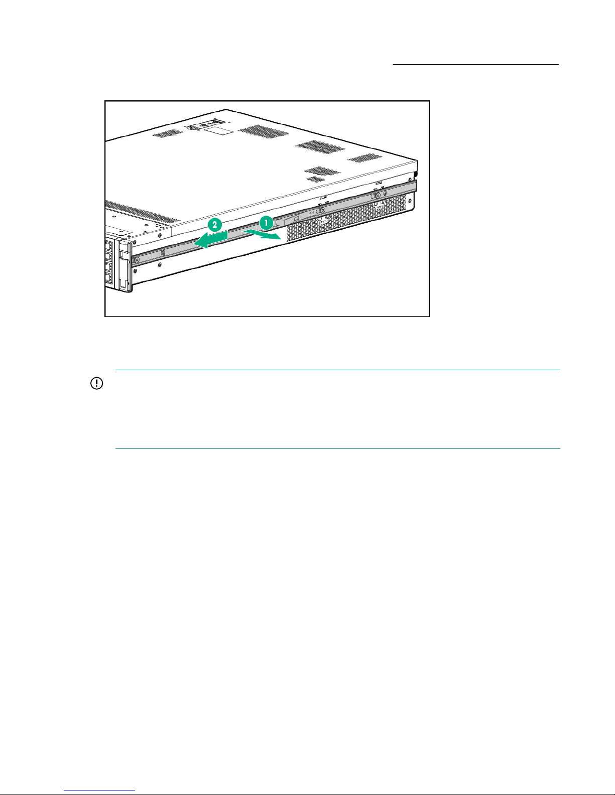
1. Slightly pull the rail lock away from the rail to unlock the rail. See Removing the rails from the server
2. Slide the rail toward the front of the server to disengage the rail from the posts on the server.
3. Repeat these steps for the rail on the other side of the server.
Figure 1: Removing the rails from the server
Attaching the pedestal kit top and bottom
IMPORTANT:
In this document the server top, bottom, right and left refer to the server as faced from the front with
the server in a horizontal orientation. The pedestal kit components are referred to by the final
position with the server in a vertical orientation. For example, the pedestal kit bottom attaches to the
server right side
6 Attaching the pedestal kit top and bottom
Page 7
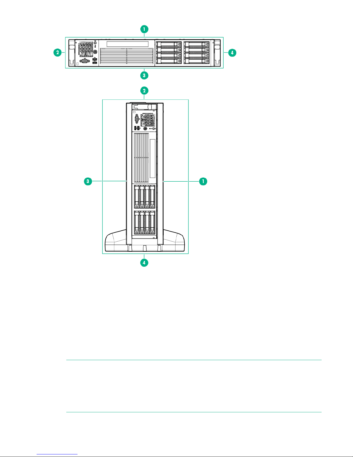
Figure 2: Front of server
1. Server top/pedestal right
2. Server left/pedestal top
3. Server bottom/pedestal left
4. Server right/pedestal bottom
The pedestal kit bottom attaches to the right side of the server when the server is in the horizontal
position. The pedestal kit top attaches to the left side of the server when in the server is in the horizontal
position. The pedestal bottom can be distinguished from the pedestal top by the pedestal feet slots.
Procedure
NOTE:
The bottom piece of the pedestal is taller than the server, so try to position the server so the right
side (in the horizontal position) of the server hangs off the edge of the work surface by a few inches
to allow the bottom piece to be attached to the server chassis. If that is not possible, then raise up
the server approximately three inches from the work surface to enable the pedestal kit bottom piece
to be attached to the server right side.
Installing the server 7
Page 8
To attach the components.
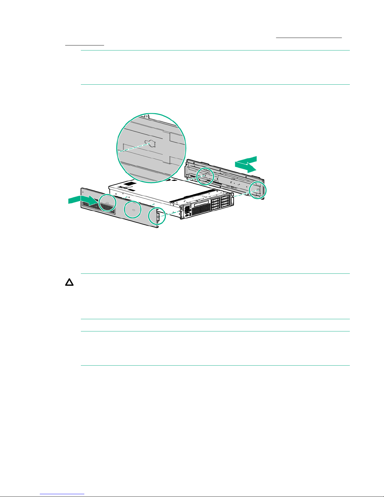
1. Align the holes in the pedestal component with the posts on the server. See Installing the pedestal
bottom piece.
NOTE:
One of the holes in the pedestal component contains the locking mechanism. This makes the
hole appear partially blocked.
2. Hold the pedestal component flush against the server.
3. Slide the pedestal component forward until it locks into place.
Figure 3: Installing the pedestal bottom piece
4. Stand the server up on the bottom piece of the pedestal kit that was just installed so the server is in
the vertical position.
CAUTION:
The server is heavy. Be careful when lifting it to the vertical position.
Without the feet installed, the server might tip over easily. Be careful when working near the
server to avoid tipping it over.
5. Align the holes in the pedestal top piece with the posts on the server
NOTE:
One of the holes in the pedestal component contains the locking mechanism. This makes the
hole appear partially blocked.
6. Hold the pedestal top piece flush against the server.
7. Slide the pedestal top piece forward until it locks into place.
8. The top and bottom pedestal kit pieces are now in place.
Attaching the bezel cover
To attach the bezel cover:
8 Attaching the bezel cover
Page 9

Procedure
1. Apply the rx2800 i6 product label provided in the pedestal kit to the bottom front of the bezel cover
2. Attach the bezel cover to the front of the server starting from the bottom of the pedestal kit.
3. Push the bezel cover into place against the pedestal kit top piece until the tabs on the bezel cover
(label can be seen in the figure below.)
snap into place.
Figure 4: Attaching the bezel cover
Attaching the pedestal kit side pieces
The pedestal kit right side piece attaches to the top of the server. The top cover of the server might have
ventilation holes in it to enable proper air flow and cooling. The right side piece of the pedestal kit also
has ventilation holes in it to enable the proper cooling and air flow. Follow these steps to attach the
pedestal kit right side piece.
CAUTION:
The ventilation holes in the pedestal kit right side piece must be matched up with the ventilation
holes on the top cover of the Integrity rx2800 i6 Server to enable proper cooling and air flow. Failure
to heed this warning causes the server to shut down with an overtemp condition.
To attach the component:
Procedure
1. Align the posts on the pedestal kit right side piece with the slots in the pedestal kit top and bottom.
2. Hold the pedestal side flush against the server and slide it toward the front of the server.
Attaching the pedestal kit side pieces 9
Page 10

Figure 5: Attaching the pedestal kit side piece
3. Secure the pedestal side by hand tightening the captive thumb screws on the rear of the server.
10 Installing the server
Page 11

Figure 6: Thumb screw locations
Repeat these steps to install the left side piece.
Attaching the pedestal feet
The pedestal feet slide into the slots on the pedestal bottom, two on each side. The feet are all the same
and can be mounted in any slot on the bottom piece of the pedestal kit.
Attaching the pedestal feet 11
Page 12

Figure 7: Attaching the feet
Connecting server cables
AC input power
The server can receive AC input from two different AC power sources. The power receptacles are located
at the rear of the server.
A maximum of two power supplies can be installed in the server. Installing two power supplies in the
server provides 1+1 redundancy, meaning that if one power supply fails, there is still enough power
supplied to the server to operate. You must promptly replace the failed power supply to restore 1+1
functionality.
All high-line (220 V) configurations are capable of 1+1 redundancy. Low-line (110 V) configurations can
maintain 1+1 redundancy as long as the total power consumed does not exceed 800 W.
A minimum of one power supply is required to power the server. If only one power supply is installed in
the server, there is no 1+1 capability.
Power states
The server has the following power states:
• Standby power
• Full power
• Off
12 Connecting server cables
Page 13

Table 1: Power states
Power states Power cable
plugged into
receptacle?
Standby power Yes No Yes No
Full power Yes Yes Yes Yes
Off No No No No
NOTE:
If the power restore feature is set to Always On through the iLO 3 MP PR command, the server
automatically powers on to the full power state when the power cord is plugged in to the server.
Ports and power supplies are located on the rear panel of the server.
Power activated through the iLO 3
PC
command; or front panel power
button activated?
Applying standby power to the server
Procedure
1. Plug the power cord into the receptacle in power supply.
2. Plug the other end of the power cord into an AC outlet.
Standby DC
voltage
applied?
DC voltage
applied?
NOTE:
The LED on the power supply does not illuminate in the standby power state. The LED is green
when the server is powered on to full power.
If the power restore feature is set to Always On through the iLO 3 MP PR command, the server
automatically powers on to the full power state when the power cord is plugged into the server.
3. If the server has two power supplies, plug the second power cord into the power supply.
4. Plug the other end of the power cord into an AC outlet.
Connecting to the LAN
The server has four LAN ports that provide network connectivity. The HPE Integrity rx2800 i6 Server User
Service Guide shows the available LAN ports for the server.
Procedure
1. Obtain valid IP addresses for each LAN port you plan to activate.
2. Connect the LAN cable from an available LAN port into a live connection on the network.
Setting up the system
For more information on using the iLO 3 MP, see the HPE Integrity iLO 3 Operations Guide.
Setup checklist
Use the checklist in Setup checklist while setting up the Integrity iLO 3.
Applying standby power to the server 13
Page 14

Table 2: Setup checklist
Step Action Procedure Status
Standard setup
1 Preparation
2 Configure the iLO 3 MP
LAN
3 Log on to the iLO 3 MP
4 Change default user
name and password
5 Set up user accounts
6 Set up security access
1. Determine an access method to select and connect
the cables.
2. Determine a LAN configuration method and assign
an IP address if necessary.
Select one of the three methods to configure the LAN
for iLO 3 MP access:
• DHCP with DNS
• RS-232 serial port
• Static IP address
Log on to the iLO 3 MP from a supported web browser
or command line using the default user name and
password.
Change the default user name and password on the
administrator account to your predefined selections.
Set up the user accounts if you are using the local
accounts feature.
Set up the security access settings.
Accessing UEFI or the OS from iLO MP
The Unified Extensible Firmware Interface is an architecture that provides an interface between the
server OS and the server firmware. UEFI provides a standard environment for booting an OS and running
preboot applications.
Use this procedure to access UEFI or the OS from the iLO MP. Your security parameters were set
regarding remote access.
NOTE:
Commands are case-insensitive.
Procedure
1. From the MP Main Menu, enter the commandco to access the Console.
NOTE:
Terminal windows must be set to a window size of 80 columns x 25 rows for optimal viewing of
the console at UEFI
2. After memory test and CPU late self test the following message appears:
Press Ctrl-C now to bypass loading option ROM UEFI drivers.
14 Accessing UEFI or the OS from iLO MP
Page 15

• Bypass loading from I/O slots.
• Bypass loading from I/O slots and core I/O.
The Bypass loading from I/O slots and core I/O option may be useful if a bad core I/O UEFI driver
is preventing system boot. USB drives can still be used at the UEFI shell to update core I/O drivers.
CAUTION:
Pressing Ctrl-C before the prompt does not work and might disable this feature. Therefore, be
sure to wait for the prompt before pressing Ctrl-C.
NOTE:
The prompt might take several minutes to appear, and the period that you can press Ctrl-C is
very short. For typical boots, Hewlett Packard Enterprise recommends that you let the prompt
time out.
After selecting an option, the boot proceeds.
NOTE:
If no option is selected, the boot proceeds after a few seconds.
3. Depending on how the server was configured from the factory and if the OS is installed at the time of
purchase, you are taken to:
a. UEFI shell prompt
b. OS login prompt
If the server has a factory-installed OS, you can interrupt the boot process to configure your specific
UEFI parameters.
If you are at the UEFI shell prompt, go to "UEFI Front Page"
If you are at the OS login prompt, go to "OS login prompt"
UEFI Front Page
If you are at the UEFI shell prompt, enter the command exit to navigate to the UEFI Front Page
UEFI Front Page 15
Page 16

Figure 8: Shell map page
Figure 9: UEFI front page
To view boot options, or launch a specific boot option, press B to launch the Boot Manager.
16 Installing the server
Page 17

Figure 10: Boot Manager screen
To configure specific devices, press D to launch the Device Manager. This is an advanced feature and
must only be performed when directed.
Figure 11: Device Manager screen
To perform maintenance on the system such as adding, deleting, or reordering boot options, press M to
launch the Boot Maintenance Manager.
Installing the server 17
Page 18

Figure 12: Boot Maintenance Manager screen
To perform more advanced operations, press S to launch the UEFI Shell.
To view the iLO LAN configuration, press I to launch the iLO Setup Tool.
Saving UEFI configuration settings
You can configure other UEFI settings at this time. For more UEFI configuration options, see the HPE
Integrity rx2800 i6 Server User Service Guide.
Booting and installing the operating system
From the UEFI Front Page prompt, you can boot and install in either of two manners:
• If your OS is loaded onto your server, see Operating System Is loaded onto the server.
.
• If the OS is not installed onto your server, see Operating system is not loaded onto the server
.
Operating system is loaded onto the server
If the OS is loaded on your server, normally UEFI automatically boots to the OS. If the UEFI Front Page is
loaded, press ENTER t to start auto boot, or B to select a specific boot option for your OS.
• Use your standard OS login procedures, or see your OS documentation to log in to your OS.
Operating system is not loaded onto the server
If the OS is not already on the server, the three installation options are: using Ignite UX or vMedia, or
loading from a DVD.
18 Saving UEFI configuration settings
Page 19

OS login prompt
If your server is at the OS login prompt after you establish a connection to the server, use your standard
OS log in procedures, or see your OS documentation for the next steps.
Powering on and powering off the server
Power states
The server has the following power states:
• Standby power
• Full power
• Off
Table 3: Power states
Power states Power cable
plugged into
receptacle?
Standby power Yes No Yes No
Full power Yes Yes Yes Yes
Off No No No No
NOTE:
If the power restore feature is set to Always On through the iLO 3 MP PR command, the server
automatically powers on to the full power state when the power cord is plugged in to the server.
Ports and power supplies are located on the rear panel of the server.
Powering on the server
Power on the server to full power using the following methods if the server is in the standby power state:
• iLO 3 MP PC command
• Power button
Power activated through the iLO 3
PC
command; or front panel power
button activated?
Standby DC
voltage
applied?
DC voltage
applied?
Powering on the server using the iLO 3 MP
NOTE:
If the power restore feature is set to Always On through the iLO 3 MP PR command, the server
automatically powers on to the full power state when the power cord is plugged in to the server.
Procedure
1. Plug all power cables into the receptacles on the rear panel of the server.
2. Initiate a console session, and access the MP Main Menu.
3. Enter the commandCM to enable command mode.
OS login prompt 19
Page 20

4. Enter the commandPC to use the remote power control command. A command output similar to the
one shown below will appear:
NOTE:
Your display may not match the display shown.
Figure 13: Power Control Menu screen
5. Enter the command ON to power on the server, and enter YES when prompted to confirm the action.
6. Boot the operating system.
For more information, see the operating system documentation.
Powering on the server manually
NOTE: If the power restore feature is set to Always On through the iLO 3 MP PR command, the
server automatically powers on to the full power state when the power cord is plugged in to the
server.
Procedure
1. Plug all power cables into the receptacles on the rear panel of the server.
2. Press the power button to start the server.
3. Start the operating system. For more information, see the operating system documentation.
Powering off the server
If the server is in the standby or full power state, power off the server by using either of the following
methods:
• iLO 3 MP PC command
• Power button
Powering off the server using the iLO 3 MP
Procedure
1. Gracefully shut down the operating system. See the operating system documentation for more
information.
2. Initiate a console session, and access the MP Main Menu.
20 Powering on the server manually
Page 21

3. Enter CM to enable command mode.
4. Enter PC to use the remote power control command.
5. Enter OFF to power off the server, and enter YES when prompted to confirm the action.
CAUTION:
The main DC voltage is now removed from the system However, AC voltage for standby power
is still present in the server.
6. Unplug all power cables from the receptacles on the rear panel of the server.
Powering off the server manually
Procedure
1. Gracefully shut down the operating system. For more information, see the operating system
documentation.
2. To power off the server, press the power button.
CAUTION:
The main DC voltage is now removed from the system. However, AC voltage for standby power
is still present in the server.
3. Unplug all power cables from the receptacles on the rear panel of the server.
Installing the latest firmware using Smart Update Manager
(SUM)
The Smart Update Manager utility enables you to deploy firmware components from either an easy-to-use
interface or a command line. It has an integrated hardware discovery engine that discovers the installed
hardware and the current versions of firmware in use on target servers. This prevents extraneous network
traffic by only sending the required components to the target. SUM also has logic to install updates in the
correct order and ensure all dependencies are met before deployment of a firmware update. It also
contains logic to prevent version-based dependencies from preventing a successful installation and
ensures updates are handled in a manner that reduces any downtime required for the update process.
Smart Update Manager does not require an agent for remote installations. After the installation is
complete, Smart Update Manager also removes all remote files associated with the installation.
Key features of Smart Update Manager are:
• GUI and CLI
• Dependency checking, which ensures appropriate installation order and dependency checking
between components
• Intelligent deployment of only required updates
• Improved deployment performance
• Remote command-line deployment
At this time, firmware updates on Integrity systems through SUM are done remotely. For example, SUM
runs on an x86 Linux or Windows management system and updates targeted Integrity systems through
the network. SUM supports firmware updates on rx2800 i6 servers. Firmware bundles for these servers
are available and can be downloaded from the Hewlett Packard Enterprise website at http://
www.hpe.com.
For more information about SUM, see the Smart Update Manager User Guide (http://www.hpe.com/
info/hpsum/documentation).
Powering off the server manually 21
Page 22

Support and other resources
Accessing Hewlett Packard Enterprise Support
• For live assistance, go to the Contact Hewlett Packard Enterprise Worldwide website:
http://www.hpe.com/assistance
• To access documentation and support services, go to the Hewlett Packard Enterprise Support Center
website:
http://www.hpe.com/support/hpesc
Information to collect
• Technical support registration number (if applicable)
• Product name, model or version, and serial number
• Operating system name and version
• Firmware version
• Error messages
• Product-specific reports and logs
• Add-on products or components
• Third-party products or components
Accessing updates
• Some software products provide a mechanism for accessing software updates through the product
interface. Review your product documentation to identify the recommended software update method.
• To download product updates:
Hewlett Packard Enterprise Support Center
www.hpe.com/support/hpesc
Hewlett Packard Enterprise Support Center: Software downloads
www.hpe.com/support/downloads
Software Depot
www.hpe.com/support/softwaredepot
• To subscribe to eNewsletters and alerts:
www.hpe.com/support/e-updates
• To view and update your entitlements, and to link your contracts and warranties with your profile, go to
the Hewlett Packard Enterprise Support Center More Information on Access to Support Materials
page:
www.hpe.com/support/AccessToSupportMaterials
IMPORTANT:
Access to some updates might require product entitlement when accessed through the Hewlett
Packard Enterprise Support Center. You must have an HPE Passport set up with relevant
entitlements.
22 Support and other resources
Page 23

Customer self repair
Hewlett Packard Enterprise customer self repair (CSR) programs allow you to repair your product. If a
CSR part needs to be replaced, it will be shipped directly to you so that you can install it at your
convenience. Some parts do not qualify for CSR. Your Hewlett Packard Enterprise authorized service
provider will determine whether a repair can be accomplished by CSR.
For more information about CSR, contact your local service provider or go to the CSR website:
http://www.hpe.com/support/selfrepair
Remote support
Remote support is available with supported devices as part of your warranty or contractual support
agreement. It provides intelligent event diagnosis, and automatic, secure submission of hardware event
notifications to Hewlett Packard Enterprise, which will initiate a fast and accurate resolution based on your
product's service level. Hewlett Packard Enterprise strongly recommends that you register your device for
remote support.
If your product includes additional remote support details, use search to locate that information.
Remote support and Proactive Care information
HPE Get Connected
www.hpe.com/services/getconnected
HPE Proactive Care services
www.hpe.com/services/proactivecare
HPE Proactive Care service: Supported products list
www.hpe.com/services/proactivecaresupportedproducts
HPE Proactive Care advanced service: Supported products list
www.hpe.com/services/proactivecareadvancedsupportedproducts
Proactive Care customer information
Proactive Care central
www.hpe.com/services/proactivecarecentral
Proactive Care service activation
www.hpe.com/services/proactivecarecentralgetstarted
Warranty information
To view the warranty for your product or to view the Safety and Compliance Information for Server,
Storage, Power, Networking, and Rack Products reference document, go to the Enterprise Safety and
Compliance website:
www.hpe.com/support/Safety-Compliance-EnterpriseProducts
Additional warranty information
HPE ProLiant and x86 Servers and Options
www.hpe.com/support/ProLiantServers-Warranties
HPE Enterprise Servers
www.hpe.com/support/EnterpriseServers-Warranties
HPE Storage Products
www.hpe.com/support/Storage-Warranties
Customer self repair 23
Page 24

HPE Networking Products
www.hpe.com/support/Networking-Warranties
Regulatory information
To view the regulatory information for your product, view the Safety and Compliance Information for
Server, Storage, Power, Networking, and Rack Products, available at the Hewlett Packard Enterprise
Support Center:
www.hpe.com/support/Safety-Compliance-EnterpriseProducts
Additional regulatory information
Hewlett Packard Enterprise is committed to providing our customers with information about the chemical
substances in our products as needed to comply with legal requirements such as REACH (Regulation EC
No 1907/2006 of the European Parliament and the Council). A chemical information report for this product
can be found at:
www.hpe.com/info/reach
For Hewlett Packard Enterprise product environmental and safety information and compliance data,
including RoHS and REACH, see:
www.hpe.com/info/ecodata
For Hewlett Packard Enterprise environmental information, including company programs, product
recycling, and energy efficiency, see:
www.hpe.com/info/environment
Documentation feedback
Hewlett Packard Enterprise is committed to providing documentation that meets your needs. To help us
improve the documentation, send any errors, suggestions, or comments to Documentation Feedback
(docsfeedback@hpe.com). When submitting your feedback, include the document title, part number,
edition, and publication date located on the front cover of the document. For online help content, include
the product name, product version, help edition, and publication date located on the legal notices page.
24 Regulatory information
 Loading...