

Page 1

HP Integrity rx2800 i4 Server
nl
User Service Guide
Abstract
This document contains specific information that is intended for users of this HP product.
This document provides system information, server specifications, and installation procedures for the HP Integrity rx2800 i4
Server. It also provides information on parts, troubleshooting, diagnosing server issues, and how to remove and replace server
components.
HP Part Number: AT101-9014A
Published: November 2012
Edition: 1
HP Confidential
Page 2

© Copyright 2012 Hewlett-Packard Development Company, L. P.
Legal notices
The information contained herein is subject to change without notice.
The only warranties for HP products and services are set forth in the express warranty statements accompanying such products and services. Nothing
herein should be construed as constituting an additional warranty. HP shall not be liable for technical or editorial errors or omissions contained
herein.
Acknowledgements
Intel® Itanium® is a trademark of Intel Corporation in the U.S. and other countries.
Windows® is a U.S. registered trademark of Microsoft Corporation.
Revision history
The publishing history table identifies the publication dates of this manual. Updates are made to this publication on an unscheduled, as needed,
basis. The updates will consist of a complete replacement manual and pertinent online or CD documentation.
The document printing date and part number indicate the current edition. The printing date changes when a new edition is printed. Minor changes
might be made at reprint without changing the printing date. The document part number changes when extensive changes are made. The latest
version of this document can be found online at:
http://www.hp.com/go/Integrity_Servers-docs
Table 1 Publishing history details
Document manufacturing
part number
AT101-9014A
Operating systems
supported
• HP-UX
Publication dateEdition numberSupported product
versions
November 2012Firstrx2800 i4
Page 3

Contents
1 Overview..................................................................................................8
Server subsystems.....................................................................................................................9
Internal components.............................................................................................................9
I/O subsystem...................................................................................................................11
RAID support.....................................................................................................................11
Controls and ports..................................................................................................................12
Front panel controls and ports.............................................................................................12
Storage and media devices............................................................................................12
Rear panel controls and ports..............................................................................................13
2 Site preparation.......................................................................................14
Server dimensions and weight..................................................................................................14
Grounding.............................................................................................................................14
Server electrical specifications..................................................................................................14
System power specifications................................................................................................14
Power consumption and cooling..........................................................................................15
Server physical and environmental specifications........................................................................16
Unpacking and inspecting the server....................................................................................16
Verifying site preparation...............................................................................................16
Inspecting the shipping containers for damage.................................................................17
Unpacking the server.....................................................................................................17
Verifying the inventory...................................................................................................17
Returning damaged equipment.......................................................................................17
Unloading the server with a lifter.....................................................................................17
3 Installing the server...................................................................................18
Safety information..................................................................................................................18
Preventing electrostatic discharge..............................................................................................18
Installation sequence and checklist............................................................................................19
Installing the server into a rack or pedestal.................................................................................19
Rack installation.................................................................................................................19
HP rack.......................................................................................................................19
Non-HP rack.................................................................................................................19
Pedestal kit installation........................................................................................................19
Remove the rails from the server......................................................................................19
Attaching the pedestal kit top and bottom........................................................................20
Attaching the bezel cover...............................................................................................22
Attaching the pedestal kit side pieces..............................................................................23
Attaching the pedestal feet.............................................................................................25
Connecting server cables.........................................................................................................25
AC input power.................................................................................................................25
Power states.................................................................................................................26
Applying standby power to the server..............................................................................26
Connecting to the LAN.......................................................................................................26
Setting up the system...............................................................................................................26
Setup checklist...................................................................................................................27
Accessing UEFI or the OS from iLO MP......................................................................................27
UEFI Front Page.................................................................................................................28
Saving UEFI configuration settings...................................................................................30
Booting and installing the operating system...........................................................................30
Operating system is loaded onto the server...........................................................................31
Operating system is not loaded onto the server......................................................................31
HP Confidential Contents 3
Page 4

OS login prompt................................................................................................................31
Powering on and powering off the server...................................................................................31
Power states......................................................................................................................31
Powering on the server.......................................................................................................31
Powering on the server using the iLO 3 MP.......................................................................31
Powering on the server manually.....................................................................................32
Powering off the server.......................................................................................................32
Powering off the server using the iLO 3 MP.......................................................................32
Powering off the server manually.....................................................................................33
Installing the latest firmware using HP Smart Update Manager (HPSUM)........................................33
Troubleshooting installation issues.............................................................................................33
4 Operating system procedures.....................................................................34
Operating system supported on the server..................................................................................34
Installing the operating system onto the server............................................................................34
Installing the operating system from the DVD drive or tape drive...............................................34
Installing the operating system using HP Ignite-UX..................................................................35
Installing the operating system with Virtual Media.......................................................................35
Configuring system boot options...............................................................................................36
Booting and shutting down HP-UX.............................................................................................36
Adding HP-UX to the boot options list...................................................................................37
HP-UX standard boot..........................................................................................................37
Booting HP-UX from the UEFI Boot Manager.....................................................................38
Booting HP-UX from the UEFI Shell...................................................................................38
Booting HP-UX in single-user mode.......................................................................................38
Booting HP-UX in LVM-maintenance mode.............................................................................39
Shutting down HP-UX..........................................................................................................39
5 Optional components................................................................................40
Installing a hot-pluggable SAS hard drive..................................................................................40
Installing a hot-swappable power supply....................................................................................41
Removing the access panel......................................................................................................42
Removing the PCI riser cage.....................................................................................................43
Removing expansion slot covers................................................................................................44
Installing expansion boards.....................................................................................................45
Installing a half-length expansion board................................................................................45
Installing a full-length expansion board.................................................................................45
Installing DIMMs....................................................................................................................46
Memory configurations.......................................................................................................46
Memory riser locations and slot IDs.................................................................................46
Supported DIMM sizes...................................................................................................47
Memory loading rules and guidelines..............................................................................48
Installing DIMMs................................................................................................................48
Installing a processor..............................................................................................................50
Processor load order..........................................................................................................50
Installing a processor and heat sink module..........................................................................51
HP Trusted Platform Module (TPM).............................................................................................56
Verifying installed components in the server...............................................................................57
Completing installation............................................................................................................58
6 Troubleshooting........................................................................................59
How to contact HP..................................................................................................................59
Methodology.........................................................................................................................59
General troubleshooting methodology..................................................................................59
Recommended troubleshooting methodology ........................................................................60
Basic and advanced troubleshooting tables...........................................................................61
HP Confidential4 Contents
Page 5

Troubleshooting tools..............................................................................................................64
LEDs ................................................................................................................................65
Front panel LEDs...........................................................................................................65
System health LED.....................................................................................................66
Locator Switch/LED (UID)...........................................................................................66
SID LEDs.................................................................................................................66
FRU and CRU health LEDs.........................................................................................68
System Event Log LED................................................................................................68
Hard drive LEDs.......................................................................................................68
Optical drive...........................................................................................................70
Rear panel LEDs............................................................................................................70
Power supply...........................................................................................................71
Diagnostics.......................................................................................................................71
Online diagnostics and exercisers........................................................................................71
Online support tool availability.......................................................................................72
Online support tools list.................................................................................................72
Offline support tools list......................................................................................................73
Fault management overview................................................................................................73
HP-UX fault management.....................................................................................................73
WBEM indication providers............................................................................................73
Errors and reading error logs...................................................................................................73
Event log definitions...........................................................................................................73
Using event logs................................................................................................................74
iLO 3 MP event logs...........................................................................................................74
System event log review......................................................................................................75
Supported configurations.........................................................................................................75
System build-up troubleshooting procedure............................................................................75
Installation troubleshooting.......................................................................................................77
Installation troubleshooting methodology...............................................................................77
Installation troubleshooting using the server power button........................................................77
Server does not power on...................................................................................................77
UEFI menu is not available..................................................................................................78
Operating system does not boot..........................................................................................78
Operating system boots with issues......................................................................................78
Intermittent server issues......................................................................................................78
SATA DVD+RW drive issues................................................................................................78
SAS disk drive issues..........................................................................................................79
Console issues...................................................................................................................79
Troubleshooting the processor and memory................................................................................79
Troubleshooting the server processor....................................................................................79
Processor load order......................................................................................................79
Processor module behaviors............................................................................................79
Customer messaging policy............................................................................................80
Troubleshooting the server memory.......................................................................................82
Memory DIMM load order.............................................................................................82
Memory subsystem behaviors..........................................................................................82
Customer messaging policy............................................................................................82
Troubleshooting the power subsystem .......................................................................................83
Power subsystem behavior...................................................................................................83
Power LED button...............................................................................................................83
Troubleshooting the cooling subsystem.......................................................................................84
Cooling subsystem behavior................................................................................................84
Troubleshooting the iLO 3 MP subsystem....................................................................................85
iLO 3 MP LAN LED on the rear panel...................................................................................85
Troubleshooting the I/O subsystem ...........................................................................................85
HP Confidential Contents 5
Page 6

I/O subsystem behaviors....................................................................................................85
Customer messaging policy.................................................................................................86
Verifying SAS hard drive operation.......................................................................................87
System LAN LEDs...............................................................................................................88
Troubleshooting the boot process..............................................................................................88
Troubleshooting the firmware....................................................................................................89
Identifying and troubleshooting firmware issues......................................................................89
Updating firmware.............................................................................................................90
Troubleshooting the system console...........................................................................................90
Troubleshooting the server environment .....................................................................................91
7 Removal and replacement procedures.........................................................92
Server components list.............................................................................................................92
Required tools........................................................................................................................94
Safety considerations..............................................................................................................94
Server warnings and cautions..............................................................................................94
Preparation procedures...........................................................................................................94
Extending the server from the rack........................................................................................95
Accessing internal components for a pedestal-mounted server..................................................96
Powering off the server.......................................................................................................99
Removing the server from the rack........................................................................................99
Removing the server from the pedestal kit............................................................................100
Required tools.............................................................................................................100
Power off the server and remove cables..........................................................................100
Removing the pedestal kit..................................................................................................100
Accessing the product rear panel.......................................................................................103
Cable management arm with left-hand swing..................................................................103
Cable management arm with right-hand swing................................................................103
Removing and replacing a SAS hard drive blank......................................................................104
Removing and replacing a hot-plug SAS hard drive...................................................................104
Removing and replacing a power supply blank.........................................................................105
Removing and replacing a hot-swap power supply....................................................................105
Removing and replacing the access panel................................................................................106
Removing and replacing the optical drive filler..........................................................................107
Removing and replacing the optical drive................................................................................107
Removing and replacing a hot-swap fan..................................................................................108
Removing and replacing the power supply backplane...............................................................109
Removing and replacing the hard drive backplane....................................................................110
Removing and replacing the PCI riser cage..............................................................................111
Removing and replacing expansion slot covers.........................................................................111
Removing and replacing expansion boards..............................................................................111
Removing and replacing a half-length expansion board........................................................112
Removing and replacing a full-length expansion board.........................................................113
Removing and replacing the cache module..............................................................................114
Removing and replacing the super capacitor pack....................................................................115
Removing and replacing the processor baffle...........................................................................116
Removing and replacing a processor and heat sink module.......................................................117
Removing and replacing DIMMs.............................................................................................120
Removing and replacing the PDH battery (system battery)..........................................................122
Removing and replacing the SID.............................................................................................122
Removing and replacing the intrusion switch cable....................................................................125
Removing and replacing the system board...............................................................................126
8 Support and other resources....................................................................132
Contacting HP......................................................................................................................132
Information to collect before you contact HP........................................................................132
HP Confidential6 Contents
Page 7

HP contact information.....................................................................................................133
Online support...........................................................................................................133
Phone support............................................................................................................133
Subscription service..........................................................................................................133
HP Insight Remote Support Software........................................................................................133
Related information...............................................................................................................134
Documentation feedback..................................................................................................134
Typographic conventions...................................................................................................134
Related documents...........................................................................................................135
Customer self repair..............................................................................................................135
Standard terms, abbreviations and acronyms................................................136
A Utilities.................................................................................................137
SAS disk setup.....................................................................................................................137
Using the saupdate command...........................................................................................137
Get mode..................................................................................................................137
Set mode...................................................................................................................137
Updating the firmware using saupdate................................................................................138
Determining the Driver ID and CTRL ID................................................................................139
Using the ORCA menu-driven interface...............................................................................139
Creating a logical drive...............................................................................................140
Deleting a logical drive................................................................................................140
Adding a RAID Advanced Pack license key....................................................................140
Viewing RAID advanced pack license keys.....................................................................141
UEFI...................................................................................................................................141
UEFI shell and HP POSSE commands..................................................................................142
Drive paths in UEFI...............................................................................................................144
Using the boot maintenance manager.....................................................................................145
Boot options....................................................................................................................146
Add boot option.........................................................................................................146
Delete boot option......................................................................................................147
Change boot order.....................................................................................................147
Driver options..................................................................................................................148
Add driver option........................................................................................................148
Delete driver option.....................................................................................................149
Change driver order....................................................................................................149
Console options...............................................................................................................150
Boot from file...................................................................................................................150
Set boot next value..........................................................................................................150
Set time out value............................................................................................................151
Reset system....................................................................................................................151
iLO MP................................................................................................................................151
Index.......................................................................................................153
HP Confidential Contents 7
Page 8

1 Overview
Table 2 Hardware specifications for the server
ServerComponent
One or two Itanium quad-core or eight-core processors:Processors
• 2.53 / 2.67 GHz eight-core 32-MB cache (170W)
• 2.13 / 2.40 GHz eight-core 24-MB cache (170W)
• 2.40 / 2.67 GHz quad-core 32-MB cache (170W)
• 1.73 / 2.40 GHz quad-core 20-MB cache (130W)
Memory
Management I/O
Supports up to 24 Double Data Rate 3 (DDR3) DIMMs mounted on memory risers that attach
to the system board.
IMPORTANT: DIMMs must be rated for 1.35 volts.
Supported DIMM sizes are as follows:
• 4 GB
• 8 GB
• 16 GB
Minimum memory configuration is 8 GB (2 x 4 GB DIMMs) with a single CPU.
Maximum memory configuration 384 GB (24 x 16 GB DIMMs).
One to eight hot-plug SAS hard drivesDisk drives
I/O riser options:PCI slots
• One full height full length PCIe x8 and two low profile PCIe x4 slots
• One full height full length PCIe x8 and one low profile PCIe x8 slots
Eight port SAS core I/O card or eight port SAS core I/O card with internal RAIDSAS I/O
Four GigE LAN portsLAN I/O
One serial port, four USB 2.0 ports, one 1G/100/10 LAN port, and two VGA ports
NOTE: The serial port is intended primarily for use as a serial console port. It can be
configured through iLO 3 for use with other serial devices (subject to OS and device limitations
and dependencies).
Power supply
One SATA DVD+RW driveOptical drive
One power supply which supports dual range operation (Low-line 100-120 & High-line
200-240). At low-line only 800 watts are available.
IMPORTANT: The 800 W redundancy does not apply to all configurations.
HP Confidential8 Overview
Page 9
Server subsystems
Internal components
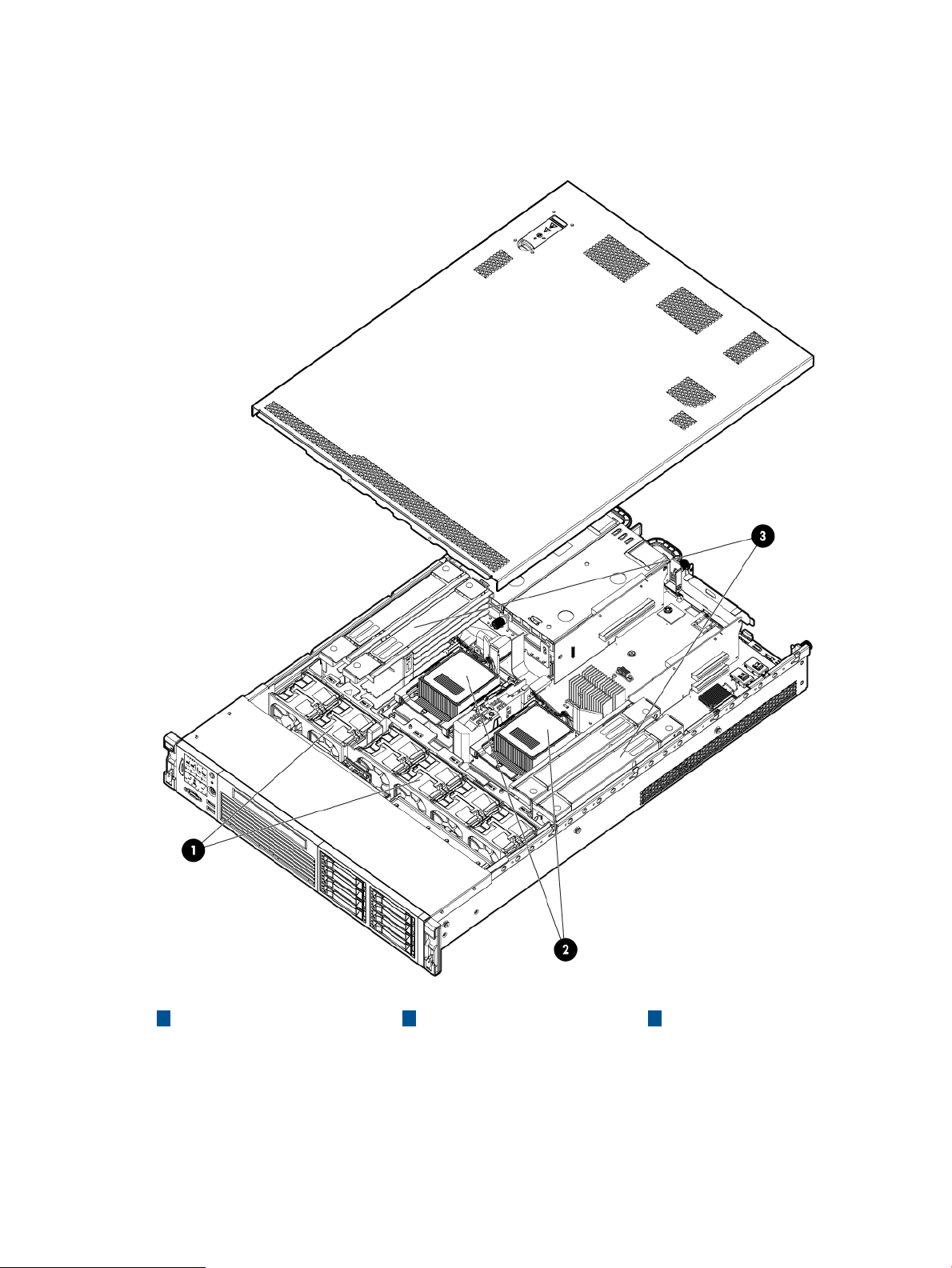
Figure 1 Internal components
321
DIMM risersProcessorsFans
HP Confidential Server subsystems 9
Page 10
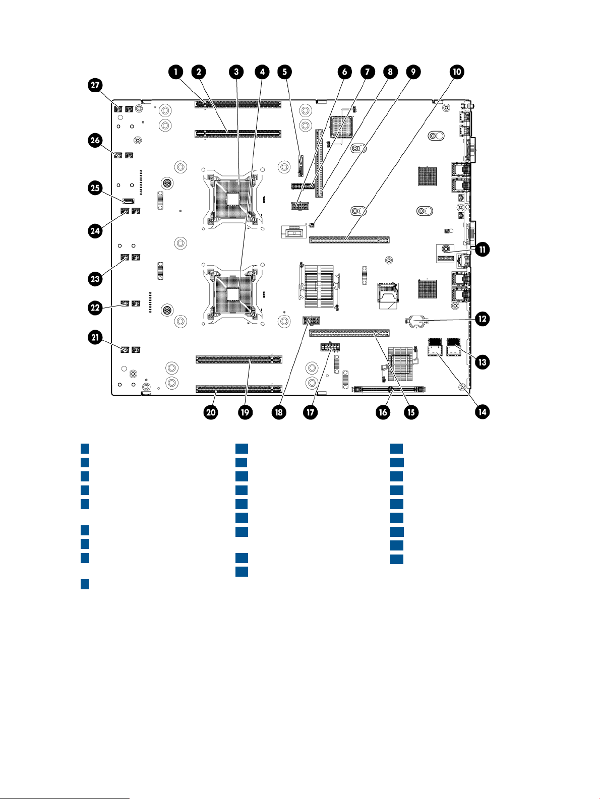
Figure 2 System board components
1
Memory riser connector 1
2
Memory riser connector 2
3
Processor socket 0
4
Processor socket 1
5
SATA optical drive
connector
6
CPU 0 power connector
7
Front I/O connector
8
Power supply backplane
connector
9
Intrusion switch connector
10
Primary riser connector
11
TPM connector
12
System battery
13
SAS B connector
14
SAS A connector
15 24
Secondary riser connector Fan 3 connector
connector
17
SAS power connector
18
CPU 1 power connector
19
Memory riser connector 3
20
Memory riser connector 4
21
Fan 6 connector
22
Fan 5 connector
23
Fan 4 connector
2516
Internal USB connectorSAS cache module
26
Fan 2 connector
27
Fan 1 connector
HP Confidential10 Overview
Page 11
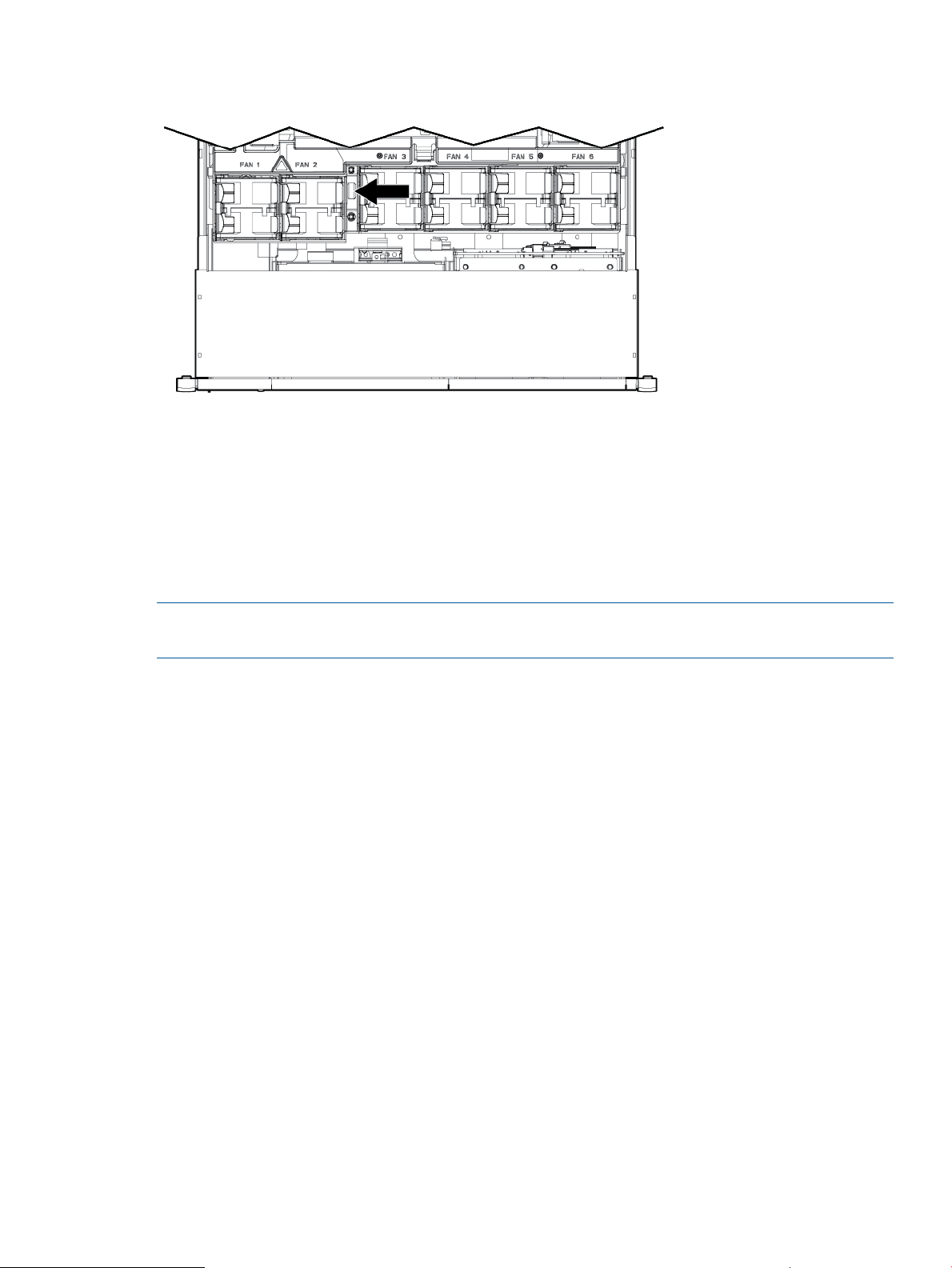
Figure 3 Internal USB location
I/O subsystem
The I/O subsystem consists of the core I/O and two optional I/O riser boards. Wake-on-LAN is
not enabled on any PCIe Public slots. The server does not support PCI Hot Plug (PHP).
The standard I/O Riser supports one full-height, full-length PCIe x8 and two full-height, half-length
PCIe x4 add-in cards. The second riser option supports one full-height, full-length PCIe x8, and one
full-height, half-length PCIe x8 add-in cards.
NOTE: All PCIe x8 slots are electrically connected as x8 slots but are physically loaded with x16
connectors.
The secondary I/O riser position can either be a riser that supports one full-height, full-length PCIe
x8 and two low-profile PCIe x4 add-in cards or a riser that supports one full-height, full-length PCIe
x8 and one low profile PCIe x8.
RAID support
The following levels of RAID support are offered:
• Zero memory
◦ Maximum 8 drives, 2 logical volumes
◦ No cache or super capacitor needed. Performance improved with cache.
• Full feature
◦ Cache needed and installing it automatically enables the full feature firmware stack.
• Advanced pack
RAID 0, 1, 10◦
RAID 0, 10, 5◦
Super capacitor is optional.
RAID 6, 50, 60◦
◦ Cache needed. Advanced Pack license must be entered to enable. Super capacitor is
required.
HP Confidential Server subsystems 11
Page 12
To enable Advanced Pack licensing, see “Adding a RAID Advanced Pack license key” (page 140).
NOTE: To utilize all 8 disks with the zero memory option, the following RAID configurations are
possible:
• RAID 0: 1 or 2 LUNs striped with up to 8 disks
• RAID 10: 1 or 2 LUNs striped & mirrored with even number of up to 8 disks
• RAID 1: 1 LUN using 2 mirrored disks, and one additional LUN in RAID 0 or 10
Example Configurations 8 Disks with Zero Memory
• LUN 1: RAID 1 bays 1 & 2
• LUN 2: RAID 0 bays 3, 4, 5, 6, & 7
• Hot Spare: bay 8
• LUN 1: RAID 10 bays 1, 2, 3, & 4
• LUN 2: RAID 10 bays 5, 6, 7, & 8
• LUN 1: RAID 0 bays 1, 2, & 3
• LUN 2: RAID 10 bays 5, 6, 7, & 8
• Hot Spare: bay 4
Controls and ports
Front panel controls and ports
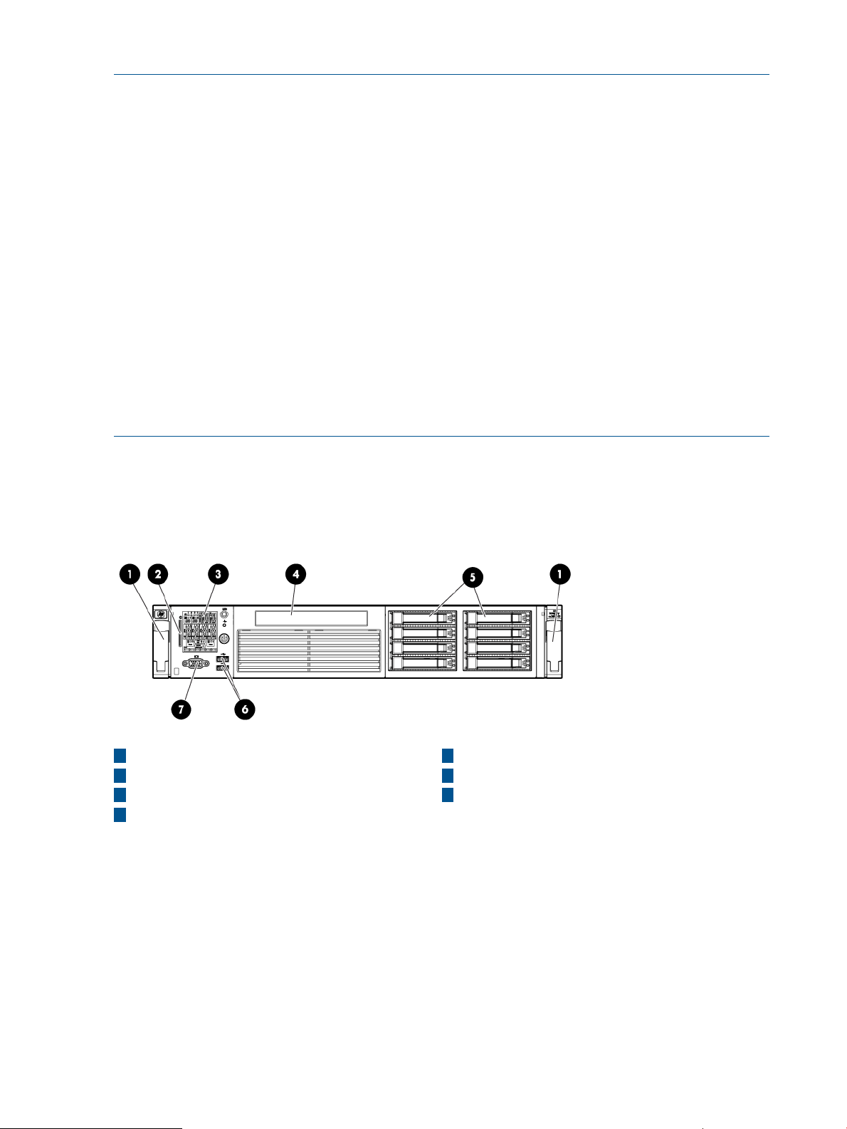
Figure 4 Front panel components
1
Quick release levers
2
iLO 3 information pull tab
SID Video connector
4
Optical drive bay
Storage and media devices
The server supports up to eight hot-plug SAS HDDs, and one optical (SATA DVD+RW) drive, with
LEDs that indicate activity and device statuses.
5
Hard drive bays
6
USB connectors
73
HP Confidential12 Overview
Page 13
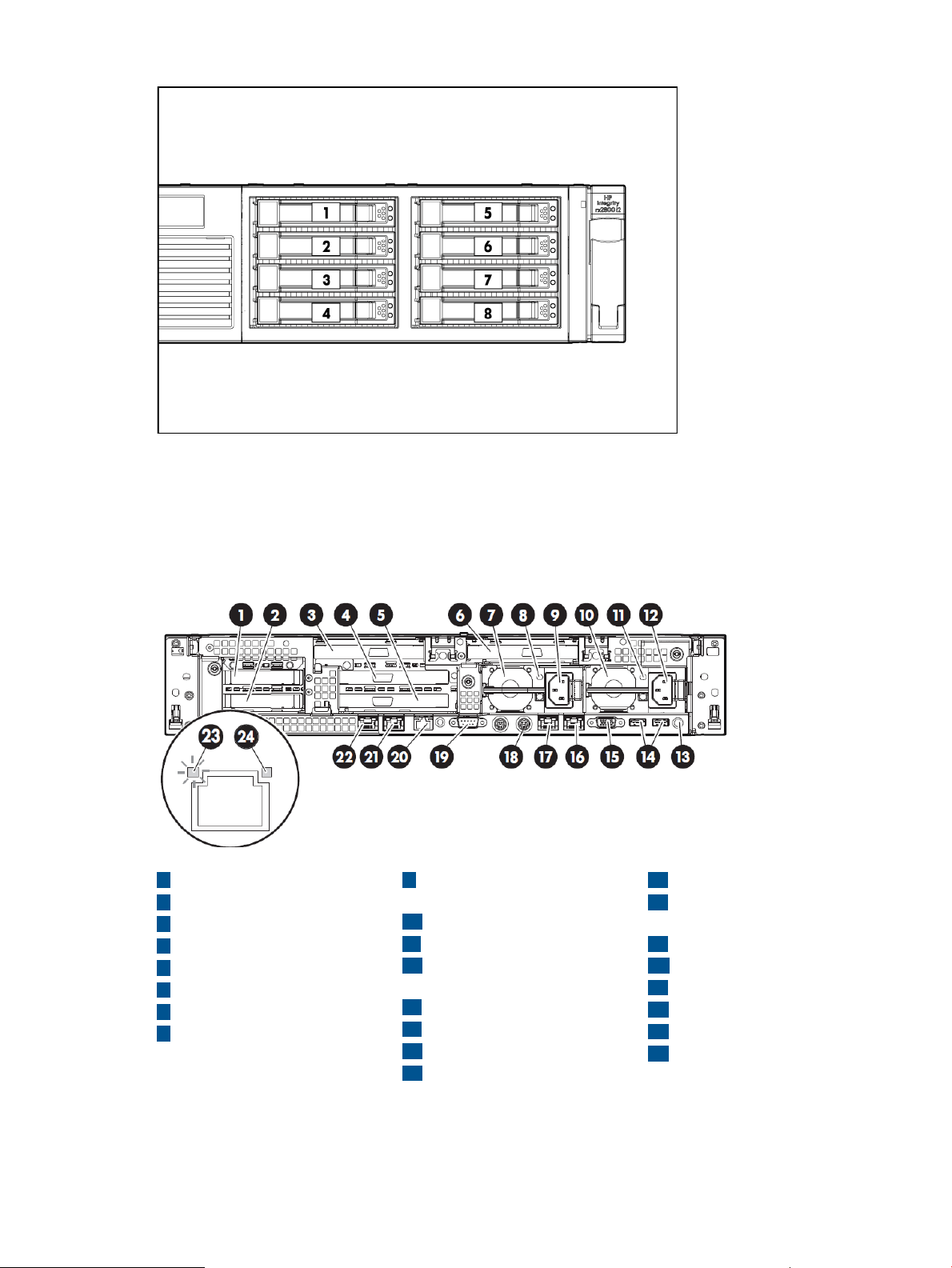
Figure 5 SAS device numbers
Rear panel controls and ports
The server rear panel includes communication ports, I/O ports, USB ports, AC power connectors,
and the locator LED and button. LEDs located on the rear panel of the server signal the operational
status of the rear panel components.
Figure 6 Rear panel components
1
PCI 5
2 18
PCI 6 iLO 3 physical presence
3
PCI 4
4
PCI 2
5
PCI 3
6
PCI 1
7
Power supply 2
8
Power supply 2 LED
9
Power supply 2 power
connector
10
Power supply 1
11
Power supply 1 LED
connector
13
UID LED button
14
USB connectors (2)
15
Video connector
16
NIC 1 connector
17
NIC 2 connector
pinhole button
19
Serial connector
2012
iLO 3 connectorPower supply 1 power
21
NIC 3 connector
22
NIC 4 connector
23
NIC link LED
24
NIC activity LED
HP Confidential Controls and ports 13
Page 14
2 Site preparation
For information on general computer room site preparation, see the HP Generalized Site Preparation
Guide on the HP website:
http://www.hp.com/go/Integrity_Servers-docs
IMPORTANT: To avoid hardware damage, allow the thermal mass of the product to equalize to
the temperature and humidity of the installation facility after removing the shipping materials. A
minimum of one hour per 10° C (50° F) of temperature difference between the shipping facility
and installation facility is required.
Server dimensions and weight
Table 3 Rack or pedestal-mounted server dimensions
Data center server dimensions
ValueDimensions and weight
69.2 cm (27.25 in)Depth
48.3 cm (19 in)Width
8.9 cm (3.5 in)Height
Maximum configuration – 30 kg (66 lb)Weight
Grounding
The site building must provide a safety ground/protective earth for each AC service entrance to
all cabinets.
Install a PE conductor that is identical in size, insulation material, and thickness to the branch-circuit
supply conductors. The PE conductor must be green with yellow stripes. The earthing conductor is
to be connected from the unit to the building installation earth or, if supplied by a separately
derived system, at the supply transformer or motor-generator set grounding point.
Server electrical specifications
System power specifications
Available power (output) is the maximum DC power that the power supply can supply to the system.
Maximum input power is what the power supply requires from the AC line to deliver that maximum
DC output (given worst case efficiency and maximum loading).
Maximum input current is the worst case/highest current given the lowest input voltage and the
maximum input power.
Table 4 System power specifications
2URack unit
Parameter
Power supply maximum output power
800 W (MAX)
+12V /66.7A MAX
900 W (MAX)
+12V /75A MAX
200 - 240 V AC110 - 120 V AC100 V ACInput voltage
6.6 A9.5 A9.3 AInput current (maximum)
57 to 63 Hz47 to 53 Hz47 to 63 HzInput frequency
1200 W (MAX)
+12V /100A MAX
HP Confidential14 Site preparation
Page 15

Table 4 System power specifications (continued)
Parameter
If an overload triggers the power supply overload protection, the system is immediately powered
off. To reset the power supply unit:
1. Disconnect the power cord.
2. Determine what caused the overload by contacting an HP support representative.
3. Reconnect the power cord.
4. Reboot the system.
NOTE: If an overload occurs twice, an undetected short circuit exists.
When you use the front panel power button to turn off the server, power consumption falls below
the low power consumption, but does not reach zero. To reach zero power consumption in "off"
mode, disconnect all power supplies from their power sources.
Power consumption and cooling
The power consumptions listed in Table 5 (page 15) are valid for the configuration shown. Please
use the HP Power Advisor tool to obtain power information for other configurations or utilization
factors.
+12VSB /2.5A MAX+12VSB /2.5A MAX+12VSB /2.5A MAX
Table 5 Standard configuration power consumption
one 1200 W power supply, and one SAS disk drive
Power consumptionStandard configuration
1228 Btu/h (maximum)360 W (maximum)One 1.46 GHz quad-core processor, 4 GB memory,
HP Confidential Server electrical specifications 15
Page 16

Server physical and environmental specifications
NOTE: De-rate maximum allowable dry-bulb temperature 1 °C/175 m above 900 m.
Table 6 Environmental specifications (system processing unit with hard disk)
Parameter
Maximum Airflow
(CFM)
1
Acoustic Noise Emission (ISO 9296)
Sound Power Level
Altitude
1
Maximum operating temperature range up to 3050 m (10000 ft). For higher altitudes, de-rate the maximum temperature
by 1° C/175 m (574 ft) above 900 m (3000 ft)
2
Two eight-core processor modules•
+5° C to +40° C (+41° F to +104° F)Operating temperature (up to 3050 m / 10000 ft)
- 40° C to +80° C (–40° F to 176° F)Non-operating temperature
+51° C (+124° F)Over-temperature shutdown
-12 ˚C DP and 8% RH to 85% RHOperating humidity
8% to 90% RH non-condensingNon-operating humidity
2
0 to 3000 m (10,000 ft) maximumOperating altitude
0 to 4,600 m (15,000 ft) maximumNon-operating altitude
Value
Office Friendly ServerData Center Server
213 CFM193 cubic feet/minute
LwAd = 6.0 BLwAd = 7.0 BMaximum configuration (disk active)
LpAm = 42.4 dBLpAm = 52.7 dBSound Pressure Level
• Twenty-four DIMMs on four memory risers
• Eight hard disk drive
• Six cards on two risers
• Two power supplies
Unpacking and inspecting the server
This section describes pre installation procedures. Ensure that you have adequately prepared your
environment for installing the new server, received the components that you ordered, and verified
that the server and the containers are in good condition after shipment.
Verifying site preparation
• Gather LAN information. The MAC addresses for the iLO 3 MP LAN and the system LAN are
located on the iLO Network Information Tag.
• Establish a method to connect to the server console.
• Verify electrical requirements. Ensure that grounding specifications and power requirements
are met.
• Validate server physical space requirements.
• Confirm environmental requirements.
For server-specific information on electrical, physical space, and environmental requirements, see
the site prep guide. For general site preparation information, see the HP Generalized Site
Preparation Guide on the HP website at http://www.hp.com/go/Integrity_Servers-docs.
HP Confidential16 Site preparation
Page 17
Inspecting the shipping containers for damage
Under normal shipping conditions, HP shipping containers protect the contents. After the equipment
arrives, carefully inspect each carton for signs of shipping damage. Shipping damage constitutes
moderate to severe damage, such as punctures in the corrugated carton, crushed boxes, or large
dents. Normal wear or slight damage to the carton is not considered shipping damage. If you find
shipping damage to the carton, immediately contact your HP customer service representative.
Unpacking the server
1. Follow the instructions printed on the outside top flap of the carton to remove the banding and
the outer carton from the server pallet.
2. Remove all inner accessory cartons and the top foam cushions, leaving only the server.
IMPORTANT: Inspect each carton for shipping damage as you unpack the server.
Verifying the inventory
The sales order packing slip lists all the equipment shipped from HP. Use this packing slip to verify
that all equipment has arrived.
NOTE: To identify each item by part number, see the sales order packing slip.
Returning damaged equipment
If the equipment is damaged, immediately contact your HP customer service representative. The
service representative initiates appropriate action through the transport carrier or the factory and
assists you in returning the equipment.
Unloading the server with a lifter
WARNING!
Use caution when using a lifter. Because of the weight of the server, to avoid injury, you must
center the server on the lifter forks before lifting it off the pallet.
NOTE: HP recommends that you follow your local guidelines when lifting equipment.
1. Unpack the server.
2. Unroll the bottom corrugated tray corresponding to the side on which the lifter is to be placed,
and then slide the server as close to that edge of the pallet as possible.
3. Break off any foam packaging that can prevent the lifter from being fully inserted under the
server. Do not remove the foam packaging from the corners of the server. This foam is required
to elevate the server and to enable the forks of the lifter to be placed under the server.
4. Insert the lifter forks under the server.
5. Carefully roll the lifter forward until it is fully positioned against the side of the server.
6. Slowly raise the server off the pallet until it clears the pallet cushions.
7. Carefully roll the lifter and server away from the pallet. Do not raise the server any higher
than necessary when moving it over to the rack.
HP Confidential Server physical and environmental specifications 17
Page 18

3 Installing the server
Safety information
Follow the instructions carefully to prevent injury and equipment damage when performing removal
and replacement procedures. Voltage might be present within the server. Many assemblies are
sensitive to damage by ESD.
Follow the safety considerations listed to ensure safe handling of components, to prevent injury,
and to prevent damage to the server:
• If installing a hot-swappable or hot-pluggable component when power is applied (fans are
running), reinstall the server cover immediately to prevent overheating.
• If installing a hot-pluggable component, complete the required software intervention prior to
removing the component.
• If installing an assembly that is neither hot-swappable nor hot-pluggable, disconnect the power
cable from the external server power receptacle before starting the installation.
WARNING! Ensure that the system is powered off and all power sources are disconnected
from the server before removing or installing server hardware (unless you are removing or
installing a hot-swappable or hot-pluggable component). Voltage is present at various locations
within the server whenever an AC power source is connected. This voltage is present even
when the main power switch is off. Failure to observe this warning might result in personal
injury or equipment damage.
• Do not wear loose clothing that might snag or catch on the server or on other components.
• Do not wear clothing subject to static charge buildup, such as wool or synthetic materials.
• If installing an internal assembly, wear an antistatic wrist strap and use a grounding mat, such
as those included in the Electrically Conductive Field Service Grounding Kit.
• Handle accessory boards and components by the edges only. Do not touch any metal edge
connectors or any electrical components on accessory boards.
Preventing electrostatic discharge
To prevent damaging the system, be aware of the precautions you need to follow when setting up
the system or handling parts. A discharge of static electricity from a finger or other conductor might
damage system boards or other static-sensitive devices. This type of damage might reduce the life
expectancy of the device.
To prevent electrostatic damage:
• Avoid hand contact by transporting and storing products in static-safe containers.
• Keep electrostatic-sensitive parts in their containers until they arrive at static-free workstations.
• Place parts on a grounded surface before removing them from their containers.
• Avoid touching pins, leads, or circuitry.
• Always be properly grounded when touching a static-sensitive component or assembly.
HP Confidential18 Installing the server
Page 19

Installation sequence and checklist
Perform site preparation (see The HP Integrity rx2800 i4 Server User Service Guide).1
Install the server into a rack or pedestal.2
Connect cables to the server.3
a. Connect the AC input power cable.
b. Connect LAN core I/O cable.
c. Connect the iLO 3 MP LAN cable.
Connect and set up the console for access.4
Power on the server.5
From iLO MP, access UEFI.6
Boot the operating system.7
Using HP Smart Update Manager (HPSUM), download the latest firmware.8
Installing the server into a rack or pedestal
CompletedDescriptionStep
Rack installation
HP rack
HP servers that are installed into racks are shipped with equipment-mounting slides. The HP 2U
Quick Deploy Rail System Installation Instructions for HP Products ships with each set of slides.
Follow the steps in this installation guide to determine where and how to install the server into the
rack.
For more information on rack deployment, stabilization and transportation, see the 10000 Series
G2 Rack Best Practices Guide.
http://www.hp.com/go/rackandpower
Non-HP rack
For information on installing a rx2800 i4 server in a third party rack, see the QuickSpecs located
on the HP Integrity rx2800 i4 Server product page at
http://h18000.www1.hp.com/products/quickspecs/14464_div/14464_div.HTML
To view the QuickSpecs, click the HTML or PDF link under Quick Specs.
Pedestal kit installation
If you order the rackless configuration option, the server ships with a pedestal mount. The pedestal
mount is packaged in a separate carton that is attached to the server carton.
Remove the rails from the server
If your server has rails when you receive it, you need to remove the rails before mounting it in the
pedestal kit. To remove the component:
1. Slightly pull the rail lock away from the rail to unlock the rail. See Figure 7 (page 20).
2. Slide the rail toward the front of the server to disengage the rail from the posts on the server.
HP Confidential Installation sequence and checklist 19
Page 20
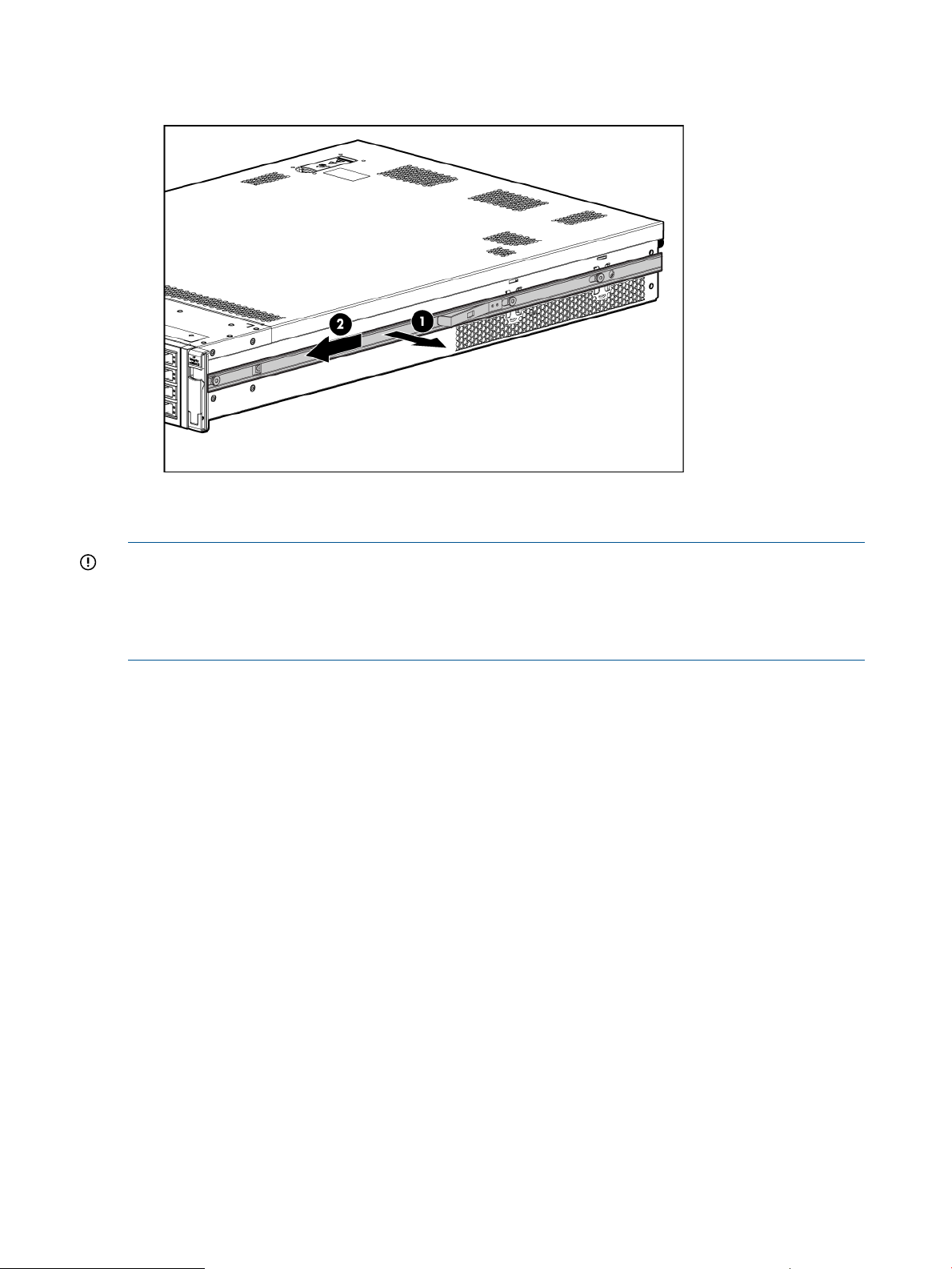
3. Repeat these steps for the rail on the other side of the server.
Figure 7 Removing the rails from the server
Attaching the pedestal kit top and bottom
IMPORTANT:
In this document the server top, bottom, right and left refer to the server as faced from the front
with the server in a horizontal orientation. The pedestal kit components are referred to by the final
position with the server in a vertical orientation. For example, the pedestal kit bottom attaches to
the server right side.
HP Confidential20 Installing the server
Page 21
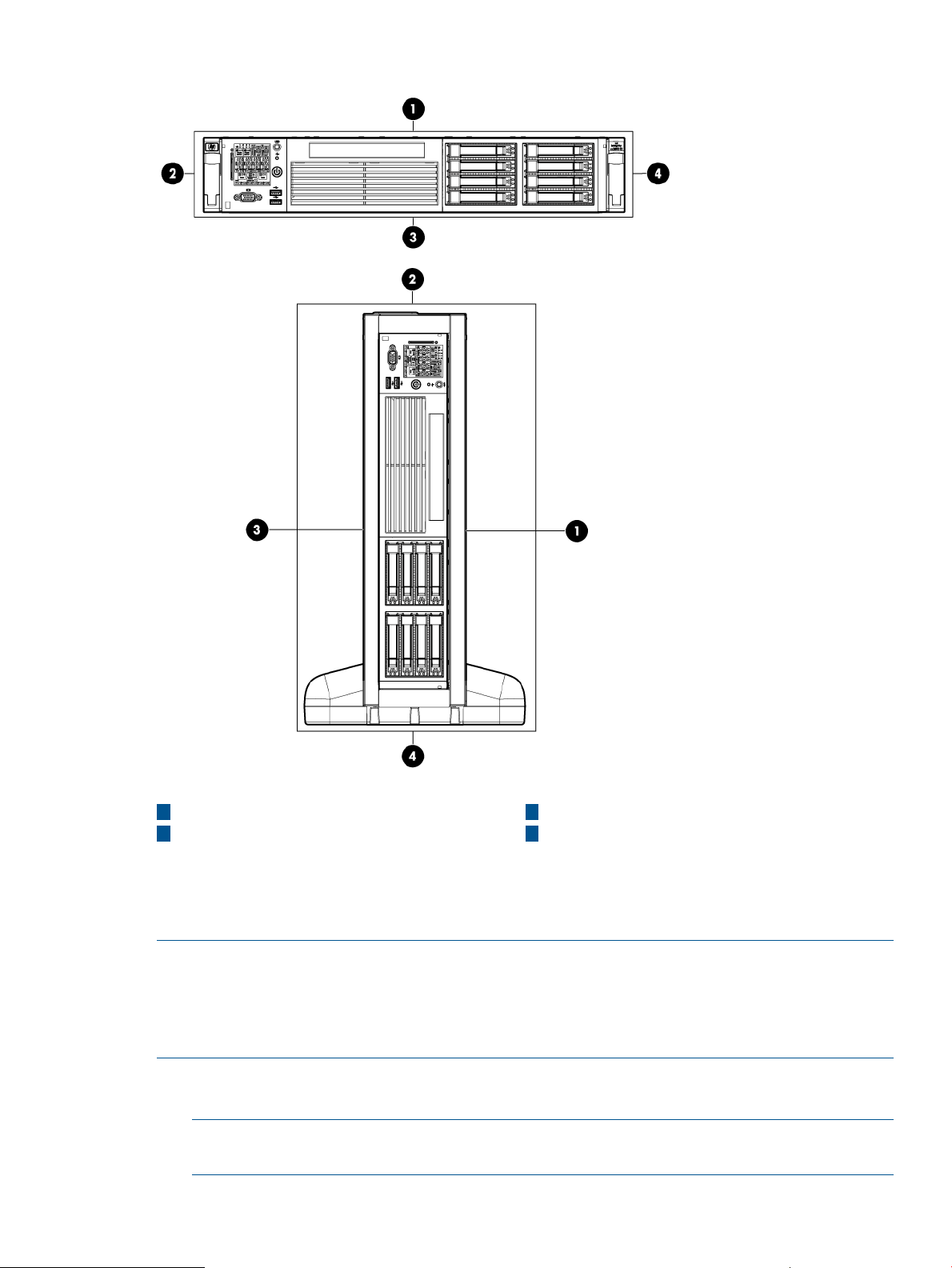
Figure 8 Front of server
1
Server top/pedestal right
2 4
Server left/pedestal top Server right/pedestal bottom
3
Server bottom/pedestal left
The pedestal kit bottom attaches to the right side of the server when the server is in the horizontal
position. The pedestal kit top attaches to the left side of the server when in the server is in the
horizontal position. The pedestal bottom can be distinguished from the pedestal top by the pedestal
feet slots.
NOTE: The bottom piece of the pedestal is taller than the server, so try to position the server so
the right side (in the horizontal position) of the server hangs off the edge of the work surface by a
few inches to allow the bottom piece to be attached to the server chassis. If that is not possible,
then raise up the server approximately three inches from the work surface to enable the pedestal
kit bottom piece to be attached to the server right side.
To attach the components.
1. Align the holes in the pedestal component with the posts on the server. See Figure 9 (page 22).
NOTE: One of the holes in the pedestal component contains the locking mechanism. This
makes the hole appear partially blocked.
HP Confidential Installing the server into a rack or pedestal 21
Page 22
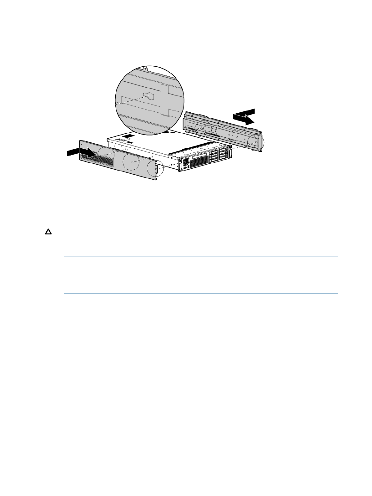
2. Hold the pedestal component flush against the server.
3. Slide the pedestal component forward until it locks into place.
Figure 9 Installing the pedestal bottom piece
4. Stand the server up on the bottom piece of the pedestal kit that was just installed so the server
is in the vertical position.
CAUTION: The server is heavy. Be careful when lifting it to the vertical position.
Without the feet installed, the server might tip over easily. Be careful when working near the
server to avoid tipping it over.
5. Align the holes in the pedestal top piece with the posts on the server.
NOTE: One of the holes in the pedestal component contains the locking mechanism. This
makes the hole appear partially blocked.
6. Hold the pedestal top piece flush against the server.
7. Slide the pedestal top piece forward until it locks into place.
8. The top and bottom pedestal kit pieces are now in place.
Attaching the bezel cover
To attach the bezel cover:
1. Apply the rx2800 i4 product label provided in the pedestal kit to the bottom front of the bezel
cover (label can be seen in the figure below.)
2. Attach the bezel cover to the front of the server starting from the bottom of the pedestal kit.
3. Push the bezel cover into place against the pedestal kit top piece until the tabs on the bezel
cover snap into place.
HP Confidential22 Installing the server
Page 23
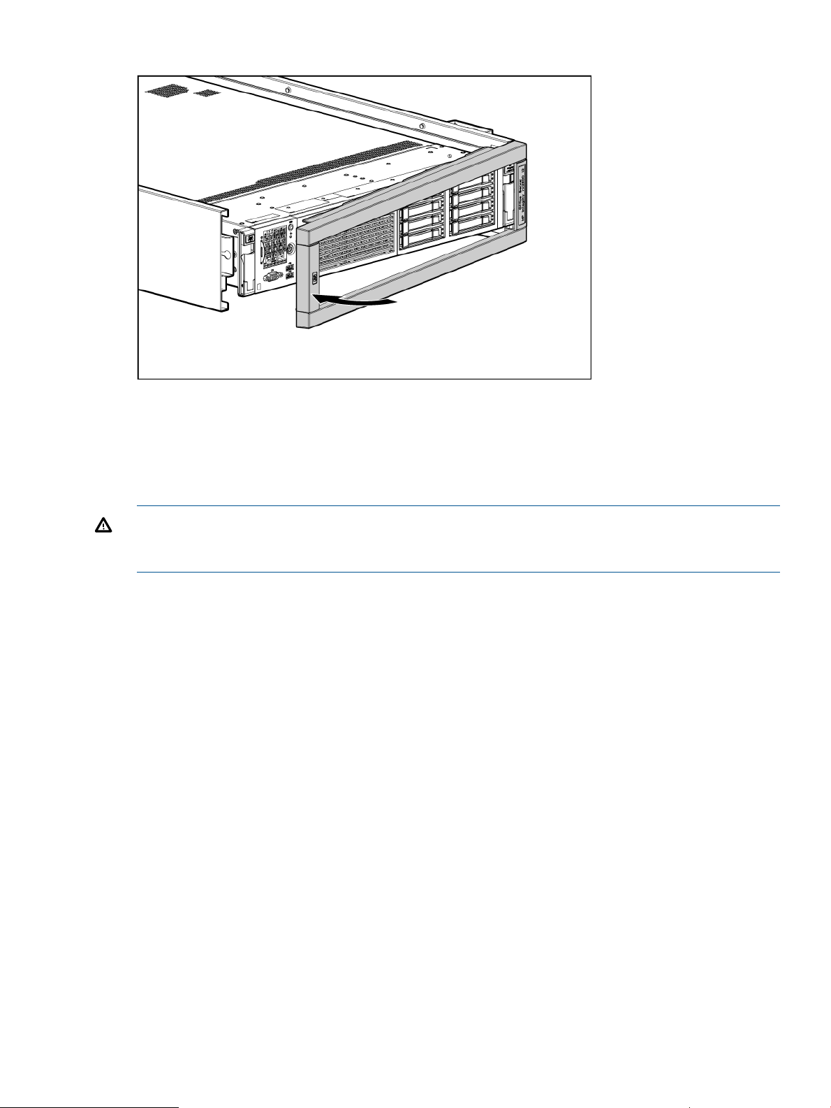
Figure 10 Attaching the bezel cover
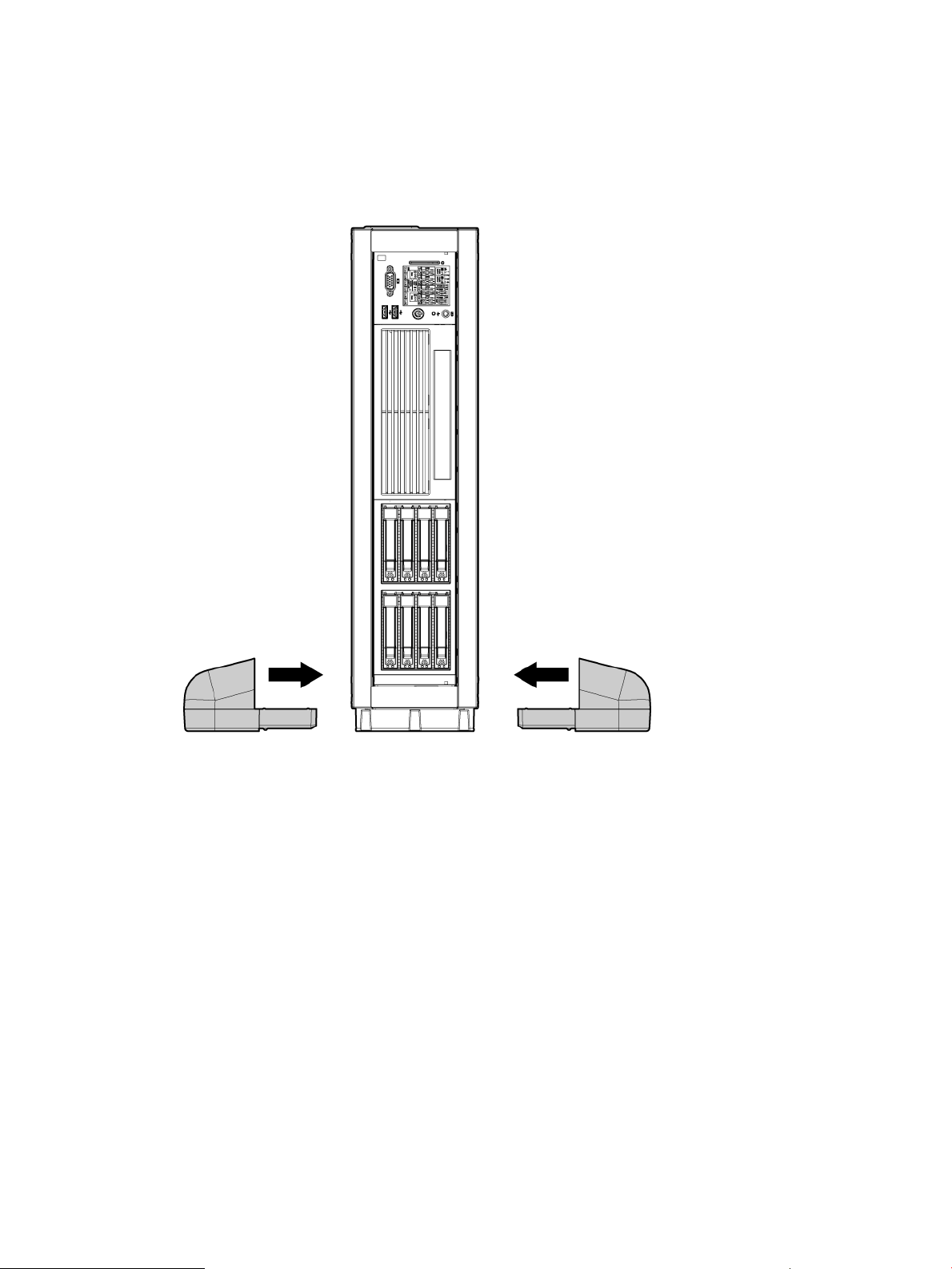
Attaching the pedestal kit side pieces
The pedestal kit right side piece attaches to the top of the server. The top cover of the server might
have ventilation holes in it to enable proper air flow and cooling. The right side piece of the
pedestal kit also has ventilation holes in it to enable the proper cooling and air flow. Follow these
steps to attach the pedestal kit right side piece.
WARNING! The ventilation holes in the pedestal kit right side piece must be matched up with
the ventilation holes on the top cover of the HP Integrity rx2800 i4 Server to enable proper cooling
and air flow. Failure to heed this warning causes the server to shut down with an overtemp condition.
To attach the component:
1. Align the posts on the pedestal kit right side piece with the slots in the pedestal kit top and
bottom.
2. Hold the pedestal side flush against the server and slide it toward the front of the server.
HP Confidential Installing the server into a rack or pedestal 23
Page 24
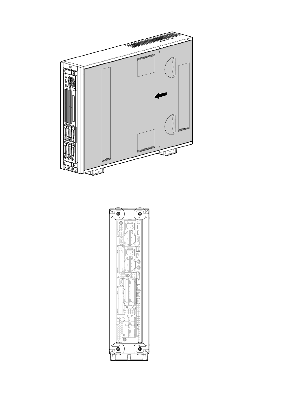
Figure 11 Attaching the pedestal kit side piece
3. Secure the pedestal side by hand tightening the captive thumb screws on the rear of the server.
Figure 12 Thumb screw locations
HP Confidential24 Installing the server
Page 25
Repeat these steps to install the left side piece.
Attaching the pedestal feet
The pedestal feet slide into the slots on the pedestal bottom, two on each side. The feet are all the
same and can be mounted in any slot on the bottom piece of the pedestal kit.
Figure 13 Attaching the feet
Connecting server cables
AC input power
The server can receive AC input from two different AC power sources. The power receptacles are
located at the rear of the server.
A maximum of two power supplies can be installed in the server. Installing two power supplies in
the server provides 1+1 redundancy, meaning that if one power supply fails, there is still enough
power supplied to the server to operate. You must promptly replace the failed power supply to
restore 1+1 functionality.
All high-line (220 V) configurations are capable of 1+1 redundancy. Low-line (110 V) configurations
can maintain 1+1 redundancy as long as the total power consumed does not exceed 800 W.
A minimum of one power supply is required to power the server. If only one power supply is
installed in the server, there is no 1+1 capability.
HP Confidential Connecting server cables 25
Page 26
Power states
The server has the following power states:
• Standby power
• Full power
• Off
Table 7 Power states
Power states
Power cable
plugged into
receptacle?
Power activated through the iLO 3 PC
command; or front panel power button
activated?
Standby DC
voltage applied?
DC voltage
applied?
NoYesNoYesStandby power
YesYesYesYesFull power
NoNoNoNoOff
CAUTION: If the server is expected to remain in standby mode for more than 30 minutes, AC
power should be completely removed from the server. You can do this by switching off the circuit
breakers that are part of the building installation, disconnecting or switching off a power distribution
unit, or by physically removing the power cords from the server.
Be aware that removing AC power from the server for an extended period can drain the system
battery.
NOTE: If the power restore feature is set to Always On through the iLO 3 MP PR command, the
server automatically powers on to the full power state when the power cord is plugged in to the
server.
The HP Integrity rx2800 i4 Server User Service Guide shows the ports and power supplies located
on the rear panel of the server.
Applying standby power to the server
1. Plug the power cord into the receptacle in power supply.
2. Plug the other end of the power cord into an AC outlet.
NOTE: The LED on the power supply does not illuminate in the standby power state. The
LED is green when the server is powered on to full power.
If the power restore feature is set to Always On through the iLO 3 MP PR command, the server
automatically powers on to the full power state when the power cord is plugged into the server.
3. If the server has two power supplies, plug the second power cord into the power supply.
4. Plug the other end of the power cord into an AC outlet.
Connecting to the LAN
The server has four LAN ports that provide network connectivity. The HP Integrity rx2800 i4 Server
User Service Guide shows the available LAN ports for the server.
1. Obtain valid IP addresses for each LAN port you plan to activate.
2. Connect the LAN cable from an available LAN port into a live connection on the network.
Setting up the system
For more information on using the iLO 3 MP, see the HP Integrity iLO 3 Operations Guide.
HP Confidential26 Installing the server
Page 27

Setup checklist
Use the checklist in Table 8 while setting up the Integrity iLO 3.
Table 8 Setup checklist
Standard setup
StatusProcedureActionStep
Preparation1 1. Determine an access method to select and connect the
cables.
2. Determine a LAN configuration method and assign an IP
address if necessary.
Configure the iLO 3 MP LAN2
Log on to the iLO 3 MP3
4
Change default user name and
password
Set up user accounts5
Select one of the three methods to configure the LAN for iLO
3 MP access:
• DHCP with DNS
• RS-232 serial port
• Static IP address
Log on to the iLO 3 MP from a supported web browser or
command line using the default user name and password.
Change the default user name and password on the
administrator account to your predefined selections.
Set up the user accounts if you are using the local accounts
feature.
Set up the security access settings.Set up security access6
Accessing UEFI or the OS from iLO MP
The Unified Extensible Firmware Interface is an architecture that provides an interface between the
server OS and the server firmware. UEFI provides a standard environment for booting an OS and
running preboot applications.
Use this procedure to access UEFI or the OS from the iLO MP. Your security parameters were set
regarding remote access.
NOTE: Commands are case-insensitive.
1. From the MP Main Menu, enter the commandco to access the Console.
NOTE: Terminal windows must be set to a window size of 80 columns x 25 rows for optimal
viewing of the console at UEFI.
2. After memory test and CPU late self test the following message appears:
Press Ctrl-C now to bypass loading option ROM UEFI drivers.
The prompt times out if Ctrl-C is not pressed within a few seconds. If Ctrl-C is pressed, you are
presented with two options:
• Bypass loading from I/O slots.
• Bypass loading from I/O slots and core I/O.
The Bypass loading from I/O slots and core I/O option may be useful if a bad core I/O
UEFI driver is preventing system boot. USB drives can still be used at the UEFI shell to
update core I/O drivers.
CAUTION: Pressing Ctrl-C before the prompt does not work and might disable this
feature. Therefore, be sure to wait for the prompt before pressing Ctrl-C.
HP Confidential Accessing UEFI or the OS from iLO MP 27
Page 28
After selecting an option, the boot proceeds.
NOTE: If no option is selected, the boot proceeds after a few seconds.
3. Depending on how the server was configured from the factory and if the OS is installed at
the time of purchase, you are taken to:
• UEFI shell prompt
• OS login prompt
If the server has a factory-installed OS, you can interrupt the boot process to configure your
specific UEFI parameters.
If you are at the UEFI shell prompt, go to “UEFI Front Page” (page 28).
If you are at the OS login prompt, go to “OS login prompt” (page 31).
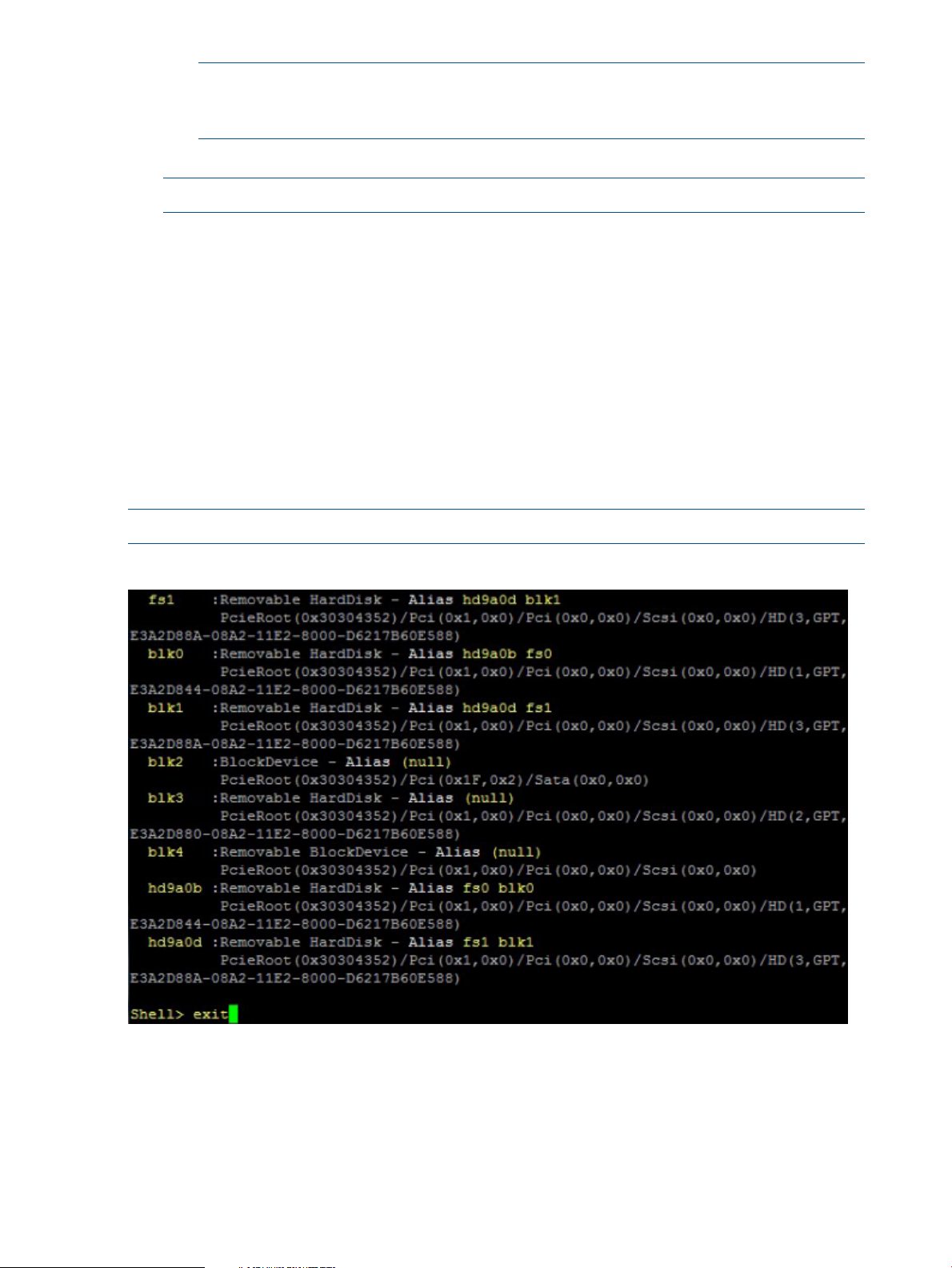
UEFI Front Page
If you are at the UEFI shell prompt, enter the command exit to navigate to the UEFI Front Page.
NOTE: The (0x30304352) means this is in Bay 2.
NOTE: The prompt might take several minutes to appear, and the period that you can
press Ctrl-C is very short. For typical boots, HP recommends that you let the prompt time
out.
Figure 14 Shell map page
HP Confidential28 Installing the server
Page 29
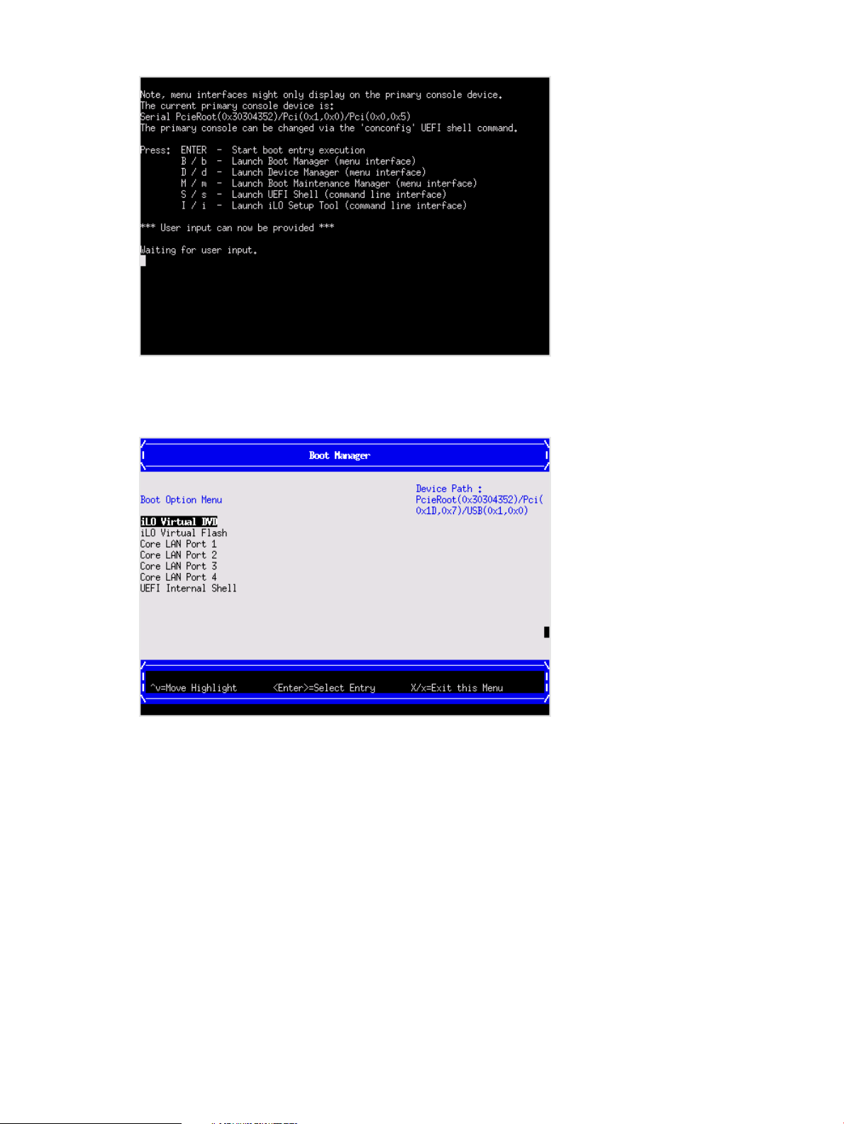
Figure 15 UEFI front page
To view boot options, or launch a specific boot option, press B to launch the Boot Manager.
Figure 16 Boot Manager screen
To configure specific devices, press D to launch the Device Manager. This is an advanced feature
and must only be performed when directed.
HP Confidential Accessing UEFI or the OS from iLO MP 29
Page 30
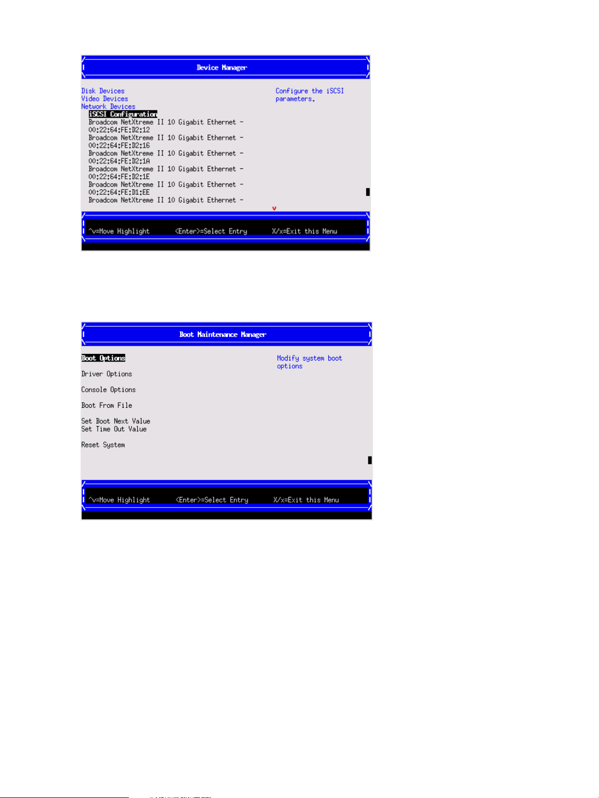
Figure 17 Device Manager screen
To perform maintenance on the system such as adding, deleting, or reordering boot options, press
M to launch the Boot Maintenance Manager.
Figure 18 Boot Maintenance Manager screen
To perform more advanced operations, press S to launch the UEFI Shell.
To view the iLO LAN configuration, press I to launch the iLO Setup Tool.
Saving UEFI configuration settings
You can configure other UEFI settings at this time. For more UEFI configuration options, see the HP
Integrity rx2800 i4 Server User Service Guide.
Booting and installing the operating system
From the UEFI Front Page prompt, you can boot and install in either of two manners:
• If your OS is loaded onto your server, see “Operating system is loaded onto the server”
(page 31).
• If the OS is not installed onto your server, see “Operating system is not loaded onto the server”
(page 31).
HP Confidential30 Installing the server
Page 31

Operating system is loaded onto the server
If the OS is loaded on your server, normally UEFI automatically boots to the OS. If the UEFI Front
Page is loaded, press ENTER to start auto boot, or B to select a specific boot option for your OS.
• Use your standard OS login procedures, or see your OS documentation to log in to your OS.
Operating system is not loaded onto the server
If the OS is not already on the server, the three options are: using Ignite-UX or vMedia, or loading
from a DVD. For details on all of these options, see the HP Integrity rx2800 i4 Server User Service
Guide.
OS login prompt
If your server is at the OS login prompt after you establish a connection to the server, use your
standard OS log in procedures, or see your OS documentation for the next steps.
Powering on and powering off the server
Power states
The server has the following power states:
• Standby power
• Full power
• Off
For details about server power states, see Table 7 (page 26).
NOTE: If the power restore feature is set to Always On through the iLO 3 MP PR command, the
server automatically powers on to the full power state when the power cord is plugged in to the
server.
Powering on the server
Power on the server to full power using the following methods if the server is in the standby power
state:
• iLO 3 MP PC command
• Power button
Powering on the server using the iLO 3 MP
NOTE: If the power restore feature is set to Always On through the iLO 3 MP PR command, the
server automatically powers on to the full power state when the power cord is plugged in to the
server.
1. Plug all power cables into the receptacles on the rear panel of the server.
2. Initiate a console session, and access the MP Main Menu.
3. Enter the commandCM to enable command mode.
4. Enter the commandPC to use the remote power control command. A command output similar
to the one shown below will appear:
NOTE: Your display may not match the display shown.
HP Confidential Powering on and powering off the server 31
Page 32

Figure 19 Power Control Menu screen
5. Enter the command ON to power on the server, and enter YES when prompted to confirm the
action.
6. Boot the operating system.
For more information, see the operating system documentation.
Powering on the server manually
NOTE: If the power restore feature is set to Always On through the iLO 3 MP PR command, the
server automatically powers on to the full power state when the power cord is plugged in to the
server.
1. Plug all power cables into the receptacles on the rear panel of the server.
2. Press the power button to start the server.
3. Start the operating system. For more information, see the operating system documentation.
Powering off the server
If the server is in the standby or full power state, power off the server by using either of the following
methods:
• iLO 3 MP PC command
• Power button
Powering off the server using the iLO 3 MP
1. Gracefully shut down the operating system. See the operating system documentation for more
information.
2. Initiate a console session, and access the MP Main Menu.
3. Enter CM to enable command mode.
4. Enter PC to use the remote power control command.
5. Enter OFF to power off the server, and enter YES when prompted to confirm the action.
CAUTION: The main DC voltage is now removed from the system However, AC voltage for
standby power is still present in the server.
6. Unplug all power cables from the receptacles on the rear panel of the server.
HP Confidential32 Installing the server
Page 33

Powering off the server manually
1. Gracefully shut down the operating system. For more information, see the operating system
documentation.
2. To power off the server, press the power button.
CAUTION: The main DC voltage is now removed from the system. However, AC voltage
for standby power is still present in the server.
3. Unplug all power cables from the receptacles on the rear panel of the server.
Installing the latest firmware using HP Smart Update Manager (HPSUM)
The HP Smart Update Manager utility enables you to deploy firmware components from either an
easy-to-use interface or a command line. It has an integrated hardware discovery engine that
discovers the installed hardware and the current versions of firmware in use on target servers. This
prevents extraneous network traffic by only sending the required components to the target. HPSUM
also has logic to install updates in the correct order and ensure all dependencies are met before
deployment of a firmware update. It also contains logic to prevent version-based dependencies
from preventing a successful installation and ensures updates are handled in a manner that reduces
any downtime required for the update process. HP Smart Update Manager does not require an
agent for remote installations. After the installation is complete, HP Smart Update Manager also
removes all remote files associated with the installation.
Key features of HP Smart Update Manager are:
• GUI and CLI
• Dependency checking, which ensures appropriate installation order and dependency checking
between components
• Intelligent deployment of only required updates
• Improved deployment performance
• Remote command-line deployment
At this time, firmware updates on Integrity systems through HPSUM are done remotely. For example,
HPSUM runs on an x86 Linux or Windows management system and updates targeted Integrity
systems through the network. HPSUM supports firmware updates on rx2800 i4 servers. Firmware
bundles for these servers are available and can be downloaded from the HP website at http://
www.hp.com.
For more information about HPSUM, see the HP Smart Update Manager User Guide (http://
www.hp.com/go/hpsum/documentation).
Troubleshooting installation issues
To troubleshoot issues that might occur during server installation, see the HP Integrity rx2800 i4
Server User Service Guide.
HP Confidential Installing the latest firmware using HP Smart Update Manager (HPSUM) 33
Page 34

4 Operating system procedures
Operating system supported on the server
• HP-UX 11i v3 HWE 1209 or later
NOTE: Wake-On-LAN (WOL) is supported with Integrity rx2800 i4 Servers running HP-UX 11i
v3.
Installing the operating system onto the server
The following procedures describe generalized operating system installation. For more details, see
the operating system documentation.
Installing the operating system from the DVD drive or tape drive
NOTE: Commands are not case-sensitive.
NOTE: Tapeboot requires an add-on AM311A Integrity Smart Array P411/256 HBA running
5.06 firmware or later.
1. Insert the OS Media into the DVD (internal to system) or tape drive (external to system).
2. Power on the server and boot to UEFI. If the server is already powered on, then using the
reset command at the UEFI prompt, reboot to UEFI.
3. From the UEFI Front Page, press S to launch the UEFI Shell.
NOTE: If the device is already selected or you already know the device name, skip the
following step.
If you are using a tape device: When the UEFI shell comes up you should see a message
similar to the following on the console:
HP Smart Array P411 Controller (version 5.06)
Tape Drive(s) Detected:
Port: 2E, box:0, bay: 5 (SAS)
If you do not see a line starting with Port and ending with (SAS), the tape is NOT connected
correctly, or it is not responding.
HP Confidential34 Operating system procedures
Page 35

4. Locate the device you want to boot from.
a. For DVD, locate the device:
fs2:\> map
Device mapping table
fs6: Removable CDRom - Alias cd66d0a blk6
PcieRoot(0x30304352)/Pci(0x1D,0x7)/USB(0x3,0x0)/CDROM(0x0)
i. To list all the device names from the UEFI Shell prompt, use the map command.
ii. From the list generated by the map command, locate the device name (in this example,
fs6).
NOTE: Your DVD drive might not be named fs6. Make sure you verify the ID
appropriate to your DVD device.
Tape will autoboot without the need to select a boot image.
iii. At the UEFI Shell prompt, specify the device name for the DVD-ROM.
iv. Enter the appropriate UEFI install command, as in the following example:
HP-UX
Shell> fs6:
fs6:\> install
b. For tape, locate the device:
• To boot from tape once you are at the UEFI shell:
Shell> tapeboot select
01
PcieRoot(0x30304352)/Pci(0x8,0x0)/Pci(0x0,0x0)/SAS(0x50060B00007F6FFC,0x0,0x1,NoTopology,0,0,0,0x0)
Select Desired Tape: 01 <<input 01
◦ If the correct media is installed, it will boot from tape when you enter the index
number.
◦ If there is no media in the SAS tape drive and you select 1, you will see the
following message:
tapeboot: Could not load tapeboot image
The operating system will start loading onto the server.
5. Follow the on-screen instructions to install the OS fully.
6. Continue with “Configuring system boot options” (page 36)
Installing the operating system using HP Ignite-UX
Ignite-UX is an HP-UX administration toolset that enables:
• Simultaneous installation of HP-UX on multiple clients
• The creation and use of custom installations
• The creation of recovery media
• The remote recovery of clients
To install the OS onto the server using Ignite-UX, go to http://www.hp.com/go/ignite-ux.
Installing the operating system with Virtual Media
NOTE: Installing the OS with Virtual Media (vMedia) might be significantly slower than installing
using other methods.
HP Confidential Installing the operating system with Virtual Media 35
Page 36

Using vMedia enables connections of a DVD physical device or image file from the local client
system to the remote server. The virtual device or image file can be used to boot the server with
an operating system that supports USB devices.
Using vMedia depends on a reliable network with good bandwidth, which is especially important
when you are performing tasks such as large file transfers or OS installations.
For more information regarding loading the OS with vMedia, see the HP Integrity iLO 3 Operations
Guide.
NOTE: After the OS is loaded, to preserve boot entries in case of failure, make sure to save your
nonvolatile memory settings.
Configuring system boot options
• Boot Manager
Contains the list of boot options available. Ordinarily, the boot options list includes the UEFI
Internal Shell and one or more operating system loaders.
To manage the boot options list for each server, use the UEFI Shell, the Boot Maintenance
Manager, or operating system utilities.
• Autoboot setting
The autoboot setting determines whether a server automatically loads the first item in the
boot options list or remains at the UEFI Front Page menu. With autoboot enabled, UEFI loads
the first item in the boot options list after a designated timeout period.
Configure the autoboot setting for an HP Integrity server using either the UEFI Shell autoboot
command or the Set Time Out Value menu item from the Boot Maintenance Manager.
Examples of autoboot commands for HP-UX:
◦ Disable autoboot from the UEFI Shell by issuing autoboot off
◦ Enable autoboot with the default timeout value by issuing autoboot on
◦ Enable autoboot with a timeout of 60 seconds by issuing autoboot 60
◦ Set autoboot from HP-UX using setboot
◦ Enable autoboot from HP-UX using setboot -b on
◦ Disable autoboot from HP-UX using setboot -b off
For more information on the autoboot command, enter help autoboot.
Booting and shutting down HP-UX
• To add an HP-UX entry to the boot options list, see “Adding HP-UX to the boot options list”
(page 37).
• To boot HP-UX, use one of the following procedures:
To boot HP-UX in the standard mode, see “HP-UX standard boot” (page 37). HP-UX boots
◦
in multi-user mode.
◦ To boot HP-UX in single-user mode, see “Booting HP-UX in single-user mode” (page 38).
◦ To boot HP-UX in LVM-maintenance mode, see “Booting HP-UX in LVM-maintenance
mode” (page 39).
• To shut down the HP-UX operating system, see “Shutting down HP-UX” (page 39).
HP Confidential36 Operating system procedures
Page 37

Adding HP-UX to the boot options list
You can add the \EFI\HPUX\HPUX.EFI loader to the boot options list from the UEFI Shell or the
Boot Maintenance Manager. For more information, see “Using the boot maintenance manager”
(page 145).
NOTE: On HP Integrity servers, the operating system installer automatically adds an entry to the
boot options list.
NOTE: To add an HP-UX boot option when logged in to HP-UX, use the setboot command.
For details, see the setboot(1M) manpage.
To add HP-UX to the list:
NOTE: Commands are not case-sensitive.
1. Access the UEFI Shell environment.
a. Log in to iLO for Integrity, and then to access the system console, enter CO.
When accessing the console, confirm that you are at the UEFI Front Page.
If you are at another UEFI menu, then choose the Exit option, or press X to exit the menu.
Exit until you return to the screen that lists the keys that can be pressed to launch various
Managers.
b. To launch the UEFI shell, press S.
2. Access the UEFI System Partition (fsX: where X is the file system number) for the device
from which you want to boot HP-UX.
For example, to access the UEFI System Partition for the bootable file system number 2, enter
fs2:. The UEFI Shell prompt changes to reflect the file system currently accessed.
The full path for the HP-UX loader is \EFI\HPUX\HPUX.EFI and is on the device you are
accessing.
3. At the UEFI Shell environment, use the bcfg command to manage the boot options list.
The bcfg command includes the following options for managing the boot options list:
• bcfg boot dump–Display all items in the boot options list for the server.
• bcfg boot rm #–Remove the item number specified by # from the boot options list.
• bcfg boot mv #a #b–Move the item number specified by #a to the position specified
by #b in the boot options list.
• bcfg boot add # file.EFI "Description"–Add a new boot option to the
position in the boot options list specified by #. The new boot option references file.EFI
and is listed with the title specified by Description.
For example, bcfg boot add 1 \EFI\HPUX\HPUX.EFI "HP-UX 11i v3" adds
an HP-UX 11i v3 item as the first.
For details, see the help bcfg command.
4. Exit the console and iLO MP interfaces.
Press Ctrl-B to exit the system console and return to the iLO 3 MP Main Menu. To exit the MP,
at the Main Menu, enter X.
HP-UX standard boot
Use either of the following procedures to boot HP-UX:
• “Booting HP-UX from the UEFI Boot Manager” (page 38)
• “Booting HP-UX from the UEFI Shell” (page 38)
HP Confidential Booting and shutting down HP-UX 37
Page 38

Booting HP-UX from the UEFI Boot Manager
1. From the UEFI Boot Manager menu, choose an item from the boot options list to boot HP-UX.
2. Access the UEFI Boot Manager menu for the server on which you want to boot HP-UX.
3. Log in to iLO MP, and then to choose the system console, enter CO.
4. Confirm you are at the UEFI Front Page. If you are at another UEFI menu, then to exit the menu,
choose the Exit option or press X. Exit until you return to the screen that lists the keys that can
be pressed to launch various Managers. To launch the Boot Manager, press B.
5. At the UEFI Boot Manager menu, choose an item from the boot options list.
Each item in the boot options list references a specific boot device and provides a specific set
of boot options or arguments you use when booting the device.
6. To initiate booting using your chosen boot option, press Enter.
7. Exit the console and iLO MP interfaces.
8. To exit the system console and return to the MP Main Menu, press Ctrl-B. To exit the MP Main
Menu, enter X at the MP Main Menu.
Booting HP-UX from the UEFI Shell
1. Access the UEFI Shell.
2. From the UEFI Front Page, press S to launch the UEFI shell.
3. Use the map command to list the file systems (fs0, fs1, and so on) that are known and have
been mapped.
4. To select a file system to use, enter the mapped name followed by a colon (:). For example,
to operate with the boot device that is mapped as fs0, at the UEFI Shell prompt, enter fs0:.
5. To launch the HPUX.EFI loader from the currently selected boot device, at the UEFI Shell
command prompt, enter HPUX.
If needed, specify the full path of loader by entering \EFI\HPUX\HPUX at the UEFI Shell
command prompt.
6. Allow the HPUX.EFI loader to proceed with the boot command specified in the AUTO file,
or manually specify the boot command.
By default, the HPUX.EFI loader boots using the loader commands found in the \EFI\HPUX\
AUTO file on the UEFI System Partition of the selected boot device. The AUTO file typically
contains the boot vmunix command.
To interact with the HPUX.EFI loader, interrupt the boot process (for example, enter a space)
within the time-out period provided by the loader. To exit the loader, use the exit command,
which returns you to UEFI.
Booting HP-UX in single-user mode
1. Use steps 1–5 from “Booting HP-UX from the UEFI Shell” (page 38) to access the UEFI shell,
and launch the HPUX.UEFI loader.
2. Access the HP-UX Boot Loader prompt (HPUX>) by pressing any key within the 10 seconds
given for interrupting the HP-UX boot process. Use the HPUX.EFI loader to boot HP-UX in
single-user mode in step 3.
After you press a key, the HPUX.EFI interface (the HP-UX Boot Loader prompt, HPUX>)
launches. For help using the HPUX.EFI loader, enter the help command. To return to the
UEFI Shell, enter exit.
3. At the HPUX.EFI interface (the HP-UX Boot loader prompt, HPUX>) enter the boot -is
vmunix command to boot HP-UX (the /stand/vmunix kernel) in single-user (-is) mode.
HP Confidential38 Operating system procedures
Page 39

Booting HP-UX in LVM-maintenance mode
The procedure for booting HP-UX into LVM Maintenance Mode is the same as for booting into
single user mode (“Booting HP-UX in single-user mode” (page 38)), except use the -lm boot option
instead of the -is boot option:
HPUX> boot -lm vmunix
Shutting down HP-UX
For more information, see the shutdown(1M) manpage.
To shut down HP-UX running on a server:
1. Log in to HP-UX running on the server that you want to shut down, or log in to iLO MP for the
server and use the Console menu to access the system console. Accessing the console through
iLO MP enables you to maintain console access to the server after HP-UX has shut down.
2. Use the shutdown command with the appropriate command-line options.
The command-line options you specify determines the way in which HP-UX shuts down and
whether the server is rebooted.
Choose an HP-UX shutdown option for your server:
• To shut down HP-UX and halt (power off) the server, use the shutdown -h command.
To reboot a halted server, power on the server by using the PC command at the iLO MP
Command menu.
• To shut down HP-UX and reboot the server, use the shutdown -r command.
HP Confidential Booting and shutting down HP-UX 39
Page 40

5 Optional components
This section describes how to install components into the server that are not factory-installed. If you
have additional components to install, be sure to install the additional components before installing
the server into your rack or pedestal configuration. Most servers are pre-configured with all
components installed before shipping from the HP factory.
Externally accessible components:
• SAS hard drives
• Power supplies
Internal components:
• Memory DIMMs
• Processors
• PCIe cards
• SAS cache module and super capacitor pack
WARNING! Ensure that the system is powered off and all power sources are disconnected from
the server prior to removing or installing server hardware (unless you are removing or installing a
hot-swappable or hot-pluggable component). Voltage is present at various locations within the
server whenever an AC power source is connected. This voltage is present even when the main
power switch is turned off. Failure to observe this warning can result in personal injury or damage
to the equipment.
Installing a hot-pluggable SAS hard drive
The front of the server has eight hot-plug SAS hard drive slots. Slots without hard drives installed
have slot fillers installed for cooling purposes.
IMPORTANT: SAS hard drives are loaded in sequence, starting with the top left slot and
proceeding down filling slots 1, 2, 3, 4 in order; and then fill the right side top to bottom 5, 6, 7,
8. See Figure 5 (page 13).
Save the hard drive filler for future use. For airflow purposes, place hard drive fillers in slots that
do not contain hard drives.
1. To remove the hard drive filler, squeeze the tab and then pull out the filler.
HP Confidential40 Optional components
Page 41

2. To install the hard drive, push in the drive and then close the locking lever.
Installing a hot-swappable power supply
The server has at least one hot-swappable power supply installed before shipping. This power
supply is located at the rear of the server. You can install a second, optional power supply to
provide N+1 capability.
Figure 20 Power supply loading guidelines
21
Power supply bay 1Power supply bay 2
CAUTION: Observe all ESD safety precautions before attempting this procedure. Failure to follow
ESD safety precautions might result in damage to the server.
CAUTION: If you do not purchase a second power supply, the empty power supply slot must
remain covered with the supplied power supply blank. Failure to observe this caution might result
in server shutdown due to overheating.
NOTE: The power supply is a hot-swappable device. You do not have to interact with the operating
system to add a power supply to the server.
HP Confidential Installing a hot-swappable power supply 41
Page 42

1. Remove the power supply blank.
2. Install the power supply.
Removing the access panel
1. Use the T-15 Torx screwdriver attached to the rear of the server to loosen the security screw
on the hood latch.
HP Confidential42 Optional components
Page 43

2. Lift the hood latch handle, and then remove the access panel.
To replace the component, reverse the removal procedure.
Removing the PCI riser cage
CAUTION: For proper cooling, do not operate the server without the access panel, baffles,
expansion slot covers, or blanks installed. If the server supports hot-pluggable components, minimize
the amount of time the access panel is open.
1. Disconnect any cables connected to optional I/O cards before removing cage.
2. Remove the PCI riser cage.
To replace the component, reverse the removal procedure. When replacing the PCI riser cage, to
ensure that it has properly seated into the system board, push down on the top of the component
where the riser is located.
HP Confidential Removing the PCI riser cage 43
Page 44

Removing expansion slot covers
CAUTION: To prevent damage to the server or expansion boards, power off the server, and
then remove all AC power cords before removing or installing the PCI riser cage.
CAUTION: For proper cooling, do not operate the server without the access panel, baffles,
expansion slot covers, or blanks installed. If the server supports hot-plug components, minimize the
amount of time the access panel is open.
1. Remove the access panel (“Removing the access panel” (page 42)).
2. Remove the PCI riser cage (“Removing the PCI riser cage” (page 43)).
3. Remove the expansion slot cover.
• To remove slot cover 1 or 4, push the retainer to release it, and then slide out the cover.
• To remove slot covers 2 and 3, lift up and remove the latch, and then remove the cover.
• To remove slot covers 5 and 6, push down on the latch, rotate the latch down, and then
remove the cover.
HP Confidential44 Optional components
Page 45

Installing expansion boards
The server supports up to two PCIe riser boards. Each PCIe riser board holds up to three PCIe
cards. The standard riser board configuration contains one riser board with one full-length, full-height
PCIe x8 slot, and two half-length, full-height PCIe x4 slots. The second board contains one full-length,
full-height PCIe x8 slot, and two half-length, half-height PCIe x4 slots.
Optionally, you can purchase a riser board that contains two full-length PCIe x8 slots.
Installing a half-length expansion board
1. Remove the access panel. See “Removing the access panel” (page 42).
2. Remove the PCI riser cage. See “Removing the PCI riser cage” (page 43).
3. Remove the expansion slot cover. See “Removing expansion slot covers” (page 44).
4. Install the expansion board.
5. Connect any required internal cables to the expansion board.
6. Reinsert the PCI riser cage into the chassis.
7. Connect any required external cables to the expansion board.
Installing a full-length expansion board
1. Remove the access panel. See “Removing the access panel” (page 42).
2. Remove the PCI riser cage. See “Removing the PCI riser cage” (page 43).
3. Remove the expansion slot cover. See “Removing expansion slot covers” (page 44).
4. Install the expansion board.
HP Confidential Installing expansion boards 45
Page 46

5. Connect any required internal cables to the expansion board.
6. Reinsert the PCI riser cage into the chassis.
7. Connect any required external cables to the expansion board.
Installing DIMMs
Memory configurations
The server has 24 system memory DIMM slots located on 4 memory risers (6 DIMMs per riser).
You can access the memory risers without removing the airflow guide or the I/O card cage.
The DIMMs are partitioned by the number of processors installed in the server. If you have only
one processor installed in the system, you can only use 12 of the 24 memory slots.
CAUTION: Observe all ESD safety precautions before attempting this procedure. Failure to follow
ESD safety precautions might result in damage to the server.
Memory riser locations and slot IDs
Install DIMMs into the risers attached to the system board. Each slot has a unique ID. For memory
riser locations, see Figure 2 (page 10).
Figure 21 DIMM slot IDs
HP Confidential46 Optional components
Page 47

Table 9 Memory Load Order
Pair number
1 Processor system (socket 0)2 Processor system (socket 0 and 1)
Memory slotsMemory riserMemory slotsMemory riser
3A and 4AMemory riser 13A and 4AMemory riser 11
3A and 4AMemory riser 23A and 4AMemory riser 32
1B and 6BMemory riser 13A and 4AMemory riser 23
1B and 6BMemory riser 23A and 4AMemory riser 44
2C and 5CMemory riser 11B and 6BMemory riser 15
2C and 5CMemory riser 21B and 6BMemory riser 36
——1B and 6BMemory riser 27
——1B and 6BMemory riser 48
——2C and 5CMemory riser 19
——2C and 5CMemory riser 310
——2C and 5CMemory riser 211
——2C and 5CMemory riser 412
IMPORTANT: A maximum of 8 DIMMs are supported in a configuration with low line AC voltage
and 2 processors.
TIP: You can load DIMM pairs on a single riser at a time, but this option reduces system
performance.
Supported DIMM sizes
DIMMs seat onto the four memory risers that seat on the system board. The minimum server
configuration requires that at least one memory pair (group of two DIMMs) is installed on memory
riser 1.
Supported DIMM sizes:
• 4 GB
• 8 GB
• 16 GB
HP Confidential Installing DIMMs 47
Page 48

Memory loading rules and guidelines
CAUTION: Failure to observe the following cautions results in system degradation or failure:
• Only ECC DIMMs are supported.
• Load DIMM pairs from largest to smallest capacity. For example, if you have a pair of 4 GB
DIMMs and a pair of 8 GB DIMMs, install the pair of 8 GB DIMMs first.
NOTE: Faster DIMMs and slower DIMMs can be installed on different slots within the same
channel, but faster DIMMs operate at the timing of the slowest DIMM populated.
• Alternate loading between installed processors. Do not install DIMMs if the corresponding
processor is not installed.
• Spread DIMMs evenly between processors.
• Load DIMMs in pairs by increasing letter.
• For best performance, install DIMM pairs in the specified sequence shown in Table 9. DIMMs
can be loaded in an economic order, for example, loading the first riser full before loading
DIMMs on other memory risers, but the DIMMs must still follow the basic DIMM load sequence.
◦ Load highest density DIMMs first.
◦ Load DIMMs in pairs by increasing letter.
• Mixed DIMM types are supported with the following qualifications:
◦ DIMMs with x4 and x8 modes can be mixed.
◦ DIMMs with different sizes can be mixed.
◦ DIMMs with different rows, columns, bank, and rank numbers can be mixed.
◦ Do not mix unbuffered DIMMs with registered DIMMs.
◦ A maximum of two unbuffered DIMMs per channel can be installed.
◦ If quad-rank DIMMs are installed for a processor, a maximum of two DIMMs can be
installed on each channel for that processor.
◦ If a channel contains quad-rank DIMMs, the quad-rank DIMM must be installed first on
the channel.
Installing DIMMs
1. Remove the access panel. See “Removing the access panel” (page 42).
2. Lift the memory riser handle and remove the component.
HP Confidential48 Optional components
Page 49

3. Install the DIMM.
HP Confidential Installing DIMMs 49
Page 50

4. Replace the memory riser.
CAUTION: Be sure to align the three stand-offs in the alignment slots.
TIP: If you see abnormal error lights after installing DIMMs, try uninstalling and reinstalling the
DIMMs and the memory riser to make sure the DIMMs and memory riser are correctly seated.
Installing a processor
The server holds one or two quad or eight-core processors that provide the following configuration
options:
Quad-core processors:
• 2.40 P1/2.67 Uncore GHz 32-MB LL cache (170W)
• 1.73 P1/2.40 Uncore GHz 20-MB LL cache (130W)
Eight-core processors:
• 2.53 P1/2.67 Uncore GHz 32-MB LL cache (170W)
• 2.13 P1/2.40 Uncore GHz 24-MB LL cache (170W)
The first processor must be installed in socket 0, and the second processor in socket 1.
CAUTION: Processor speed, number of cores, and cache size must be identical for all the
processors installed in a server. To ensure compatibility, whether upgrading, replacing, or adding
an additional processor, use processors with identical part numbers.
Failure to observe this caution results in performance degradation or server failure.
CAUTION: Observe all ESD safety precautions before attempting this procedure. Failure to follow
ESD safety precautions can result in damage to the server.
Processor load order
The server holds up to two quad-core or eight-core processors on the system board. The sockets
on the system board are labeled Module 0 and Module 1. If the server has only one processor, it
is installed in socket 0. Install the second processor in socket 1.
See Figure 2 (page 10) for the processor socket numbers.
HP Confidential50 Optional components
Page 51

Table 10 Processor load order
SocketProcessor
Module 00
Module 11
Installing a processor and heat sink module
CAUTION: The pins on the processor socket are very fragile. Any damage to them might require
replacing the system board.
CAUTION: To avoid damage to the processor, verify that the plastic tabs on the processor are
pulled fully out before installation.
CAUTION: To avoid damage to the processor, handle the processor only by the edges. Do not
touch the bottom of the processor, especially the contact area.
CAUTION: To prevent possible server malfunction and damage to the equipment, multiprocessor
configurations must contain processors with the same part number.
CAUTION: To prevent thermal instability and damage to the server, do not separate the processor
from the heat sink after assembling.
The processor and heat sink ship as separate units and are coupled during installation into the
server.
1. Open the processor cage.
HP Confidential Installing a processor 51
Page 52

2. Transfer the duplicate part/serial numbers label from the processor module to the processor
heat sink:
a. Remove the duplicate tear-away label that lists the part and serial numbers from the
processor module.
b. Place the label on the top of the heat sink.
3. Remove the processor airflow baffle.
4. Install the processor over the load posts.
NOTE: Ensure pin 1, indicated on the empty socket with an embossed triangle, matches the
pin 1 marker on the processor module, the chamfered corner of its attached voltage regulator
heat sink.
5. Remove the heat sink cover.
HP Confidential52 Optional components
Page 53

CAUTION: During installation, after removing the protective cover from the heat sink:
• Do not touch or come into contact with the thermal interface material.
• Immediately install the heat sink.
CAUTION: To avoid damage to the server and processor, ensure the processor heat sink
locking handle is fully back against the stops, rotated approximately 120° back. Also, verify
that the plastic tabs on the processor heat sink are fully pulled out before installation.
6. Install the heat sink over the load posts.
CAUTION: Do not lower the heat sink locking handle before pushing the plastic locking tabs
into place.
HP Confidential Installing a processor 53
Page 54

CAUTION: To prevent thermal instability and damage to the server, do not separate the
processor module from the processor heat sink after they have been coupled.
NOTE: Positive engagement clicking must occur during engaging of the processor heat sink
and processor module onto the socket to ensure proper seating.
HP Confidential54 Optional components
Page 55

7. Secure the heat sink to the processor.
a. Slide both plastic locking tabs into place. See callout 1 in the following figure.
b. Flip the latch down. See callout 2 in the following figure.
WARNING! The heat sink locking lever can constitute a pinch hazard. Keep your hands
on top of the lever during installation to avoid personal injury.
CAUTION: To prevent thermal instability and damage to the server, do not separate
the processor module from the processor heat sink after they have been coupled.
HP Confidential Installing a processor 55
Page 56

8. Route and connect the power cord.
CAUTION: When the processor is installed, dress all slack in the power cable to the connector
end of the cable. Failure to do so can result in pinched or damaged processor power cables.
NOTE: If you are adding an additional processor to your server, the DIMMs in the server must
be reconfigured to support both processors. For more information, see “Memory configurations”
(page 46).
HP Trusted Platform Module (TPM)
CAUTION: The TPM is not a customer-serviceable part. Once the TPM is installed on your system
board, it cannot be removed. If the TPM fails, the system board needs to be replaced by an
HP-authorized service provider. Attempting to remove the TPM from the system board will void any
existing HP service contract and cause the server to fail.
CAUTION: Any attempt to remove an installed TPM from the system board breaks or disfigures
the TPM security rivet. Upon locating a broken or disfigured rivet on an installed TPM, administrators
should consider the system compromised and take appropriate measures to ensure the integrity of
the system data.
If you suspect a TPM board failure, leave the TPM installed and remove the system board (“Removing
and replacing the system board” (page 126)). Contact an HP authorized service provider for a
replacement system board and TPM board.
HP Confidential56 Optional components
Page 57

Verifying installed components in the server
Use the following procedure to verify that the components you have installed into the server are
recognized by the server:
1. Press S to enter the UEFI shell.
2. Wait for the UEFI Shell prompt to appear.
3. Enter info all from the UEFI Shell prompt. The following appears:
NOTE: Your display might not match the display shown.
info all
SYSTEM INFORMATION
[Details omitted]
CPU INFORMATION
[Details omitted]
BOOT PROCESSOR INFORMATION
[Details omitted]
MEMORY INFORMATION
[Details omitted]
I/O INFORMATION
[Details omitted]
PCI DEVICE INFORMATION
[Details omitted]
CONSOLE CONFIGURATION
[Details omitted]
BOOT INFORMATION
[Details omitted]
FIRMWARE INFORMATION
[Details omitted]
SYSTEM SECURITY CONFIGURATION
[Details omitted]
Shell>
HP Confidential Verifying installed components in the server 57
Page 58

Completing installation
After all components are installed:
1. Close the processor cage.
2. Install the PCI riser cage.
3. Install the access panel.
4. Install the server into the rack or pedestal.
5. Connect all cables.
6. Power on the server.
HP Confidential58 Optional components
Page 59

6 Troubleshooting
The purpose of this chapter is to provide a preferred methodology (strategies and procedures) and
tools for troubleshooting the server error and fault conditions.
How to contact HP
For information on how to contact HP, see “Contacting HP” (page 132).
Methodology
General troubleshooting methodology
There are multiple entry points to the troubleshooting process, dependent upon your level of
troubleshooting expertise, the tools/processes/procedures which you have at your disposal, and
the nature of the system fault or failure.
Typically, you select from a set of symptoms, ranging from very simple (system LED is blinking) to
the most difficult (Machine Check Abort (MCA) has occurred. The following is a list of symptom
examples:
NOTE: Your output might differ from the output in the examples in this book depending on your
server and its configuration.
• Front panel LED blinking
• System alert present on console
• System will not power-up
• System will not boot
• Error/Event Message received
• Machine Check Abort (MCA) occurred
Narrow down the observed issue to the specific troubleshooting procedure required. Isolate the
failure to a specific part of the server, so you can perform more detailed troubleshooting. For
example:
• Issue- Front panel LED blinking
NOTE: The front panel health LEDs flash amber with a warning indication, or flash red with
a fault indication.
◦ System Alert on console?
Analyze the alert by using the system event log (SEL) and forward progress log (FPL), to
identify the last error logged by the server. Use the iLO 3 MP commands to view the SEL
and FPL, either through the iLO 3 MP serial text interface, or through Secure Shell, or
through the web GUI on the iLO 3 MP LAN.
You can now determine which area of the system requires further analysis. For example, if the
symptom was "system will not power-up", the initial troubleshooting procedure might indicate a
issue with the DC power rail not coming up after the power switch was turned on.
You have now reached the point where the failed CRU has been identified and needs to be
replaced. Perform the specific removal and replacement procedure, and verification steps.
NOTE: If multiple CRUs are identified as part of the solution, a fix cannot be guaranteed unless
all identified failed CRUs are replaced.
HP Confidential How to contact HP 59
Page 60

You might have to perform specific recovery procedures to finish the repair. For example, if the
system board is replaced, you need to restore customer specific information.
Should a failure occur, the System Insight Display LEDs, SEL and FPL help you identify the issue or
CRU:
• LEDs. The front panel LEDs and LAN LEDs of the server change color and blink to help identify
specific issues.
• The System Event Log (SEL) provides detailed information about the errors identified by the
LEDs.
• The Forward Progress Log (FPL) provides details about the boot progress of the server.
The System Insight Display LEDs are cleared after the issue is corrected or the CRU is replaced and
by cycling AC power.
If the LEDs, SEL and FPL do not give you enough information to identify the issue, HP also provides
diagnostic tools with each operating system (see “Troubleshooting tools” (page 64) for more
details).
NOTE: Always check the iLO 3 MP SEL in the case of a blinking yellow or red front panel LED,
before replacing any hardware. The default display mode is Keyword mode. You can also view
the error messages in Text mode.
Recommended troubleshooting methodology
The recommended methodology for troubleshooting a server error or fault is as follows:
1. Consult the system console for any messages, emails, etc., pertaining to a server error or fault.
2. View the front panel LEDs (power, SID, and system health), either locally, or remotely through
the iLO 3 MP vfp command.
3. Compare the state of the server LEDs (off; flashing or steady; red, green, or amber) with the
LED states listed in the LED Panel State Table in this section.
4. Go to the step number of the Basic Low End Troubleshooting Table, as specified in the right
column of the LED Panel State Table, located in the row which corresponds to your front panel
LED display state.
5. Read the symptom/condition information in the left column of the Basic Low End Troubleshooting
Table.
6. Perform the actions specified in the Action column.
7. If you need more details, see the appropriate subsection of this chapter, where this information
is provided in the Action column. You might be directed to access and read one or more error
logs (SEL and/or FPL).
While HP suggests that all users follow the recommended troubleshooting methodology and use
the Basic and Advanced Troubleshooting Tables in the next subsection, as a more experienced
troubleshooter, you might elect to go directly to the subsection which corresponds to your own
entry point of choice.
Table 11 provides the corresponding subsection or location title for these different entry points (for
example, if you would prefer to start by examining the logs, you can go directly to the subsection
entitled “Errors and reading error logs” (page 73)):
Table 11 Troubleshooting entry points
Front panel/System Insight Display LEDs
Subsection or locationEntry point
“Basic and advanced troubleshooting tables” (page 61) and
“Troubleshooting tools” (page 64)
“Errors and reading error logs” (page 73)System Event Log and Forward Progress Logs
HP Confidential60 Troubleshooting
Page 61

Table 11 Troubleshooting entry points (continued)
Subsection or locationEntry point
“Troubleshooting tools” (page 64)Offline and Online Diagnostics/INIT button
System Event Analyzer
“Troubleshooting tools” (page 64) (see also http://www.compaq.com/
support/svctools/webes/ for more information about this tool)
Basic and advanced troubleshooting tables
The following troubleshooting tables are designed for use by both trained and untrained support
personnel. The tables are the first tools used to determine the symptoms or condition of a suspect
server. Be aware that the state of the front panel LEDs can be viewed locally or remotely (using
the vfp command from the iLO 3 MP).
The tables are designed to cover troubleshooting symptoms from AC power-on up to booting the
operating system (OS), specifically in Steps 1-5. In most cases begin with Step 1 in Table 12,
sequencing through the table steps to locate the symptom/condition most descriptive of your current
server status; this becomes the first step in your troubleshooting procedure. Where appropriate,
an action or actions prescribed in the "Action" column of Table 12 is followed by a reference to
the corresponding subsection of this chapter for further information.
Table 12 Basic low end troubleshooting
1
Server appears "dead" -- no front panel LEDs are on,
and no fans are running.
ActionConditionStep
Nothing is logged for this condition.
1. For new server installations, review the install
procedures.
2. Verify that the power cords are connected to
both the power supplies and to the AC receptacles.
3. Verify that AC power, at the proper AC voltage
levels, is available to the receptacles.
4. Check the front panel connector and the cable
to the rest of the system.
5. If the integrated power button LED on front
panel remains off, then re-seat the power supplies,
replace the power cords, and replace the bulk
power supplies, in that order (see “Troubleshooting
the power subsystem ” (page 83)for details).
The preceding issue is fixed when the front panel
LED states are as follows: system health LED is off;
and power is steady amber.
2a
HP Confidential Methodology 61
Server does not power on after front panel power
button is momentarily pressed (less than four
seconds).
NOTE: This step assumes iLO 3 is running. If iLO
3 is not running, proceed to step 4a.
System health LED is flashing amber.2b
A fatal fault has been detected and logged,
attempting to power on the server (system health
is off, and power is steady amber).
1. Examine each power supply LED -- if not solid
green, then replace power supply (see
“Troubleshooting the power subsystem ” (page 83)
for more details).
2. Examine the iLO 3 MP logs for events related
to bulk power supplies (see “Troubleshooting the
power subsystem ” (page 83) for details).
The preceding issue is fixed when the front panel
LEDs are as follows: system health is off, and
power is solid green.
A warning or critical failure has been detected
and logged after server powers on (system health
is flashing amber, and power is steady green).
Examine each power supply LED. If not solid
Page 62

Table 12 Basic low end troubleshooting (continued)
ActionConditionStep
green, replace power supply (see “Troubleshooting
the power subsystem ” (page 83)for details).
The preceding issue is fixed when the failure
condition is corrected, and the front panel LED
states are as follows: system health is steady green,
and power is steady green.
4a
System health LED is flashing red.3
Cannot see iLO 3 MP prompt on system console -server power is off/on.
A fatal fault has been detected and logged after
attempting to power on the server (system health
is flashing red, SEL is red, and power is steady
green).
1. Examine each power supply LED. If not solid
green, replace power supply (see “Troubleshooting
the power subsystem ” (page 83)for details).
2. Check SID LED panel to identify failed or faulty
internal CRU (see “Troubleshooting tools”
(page 64) for details).
The preceding issue is fixed when a redundant,
internal CRU is replaced, and the front panel LED
states are as follows: system health is off, SEL is
off and power is steady green.
Front panel LEDs indicate that the server is either
booting or running system firmware, or is booting
or running the OS (system health is steady green,
and power is steady green). Nothing might be
logged for this condition.
1. The most common reasons for this are local
console device cabling issues, local console device
configuration issues, etc. Check these issues first.
2. Be sure that that the RS–232 configuration
matches between the server and the local console
(see “Troubleshooting the system console”
(page 90) for more details).
3. Reset iLO 3 MP, by using the iLO 3 physical
presence pinhole button on the rear panel of the
server.
4. If no change, replace the system board (see
“Removing and replacing the system board”
(page 126) for details).
The preceding issue is fixed when the iLO 3
prompt can be seen and the system health LED is
steady green.
Still no iLO 3 MP prompt on system console.4a (cont.)
Nothing might be logged for this condition (NOTE:
if the iLO 3 MP is off, the system health LED is off
as well).
Front panel LEDs indicate that the server is either
booting or running the OS (see “Troubleshooting
the boot process” (page 88) for details).
1. Verify that the proper terminal type is set:
Supported settings are hpterm, VT100+ (default),
and VTUTF8.
2. Verify that the RS-232C configuration matches
between the server and the local console or
modem (see “Troubleshooting the system console”
(page 90) for details).
3. Look for loose, damaged, or disconnected
power and signal cables on the I/O riser.
HP Confidential62 Troubleshooting
Page 63

Table 12 Basic low end troubleshooting (continued)
ActionConditionStep
The preceding issue is fixed when iLO 3 MP menu
appears on the system console, and the system
health is steady green.
Cannot see UEFI prompt on system console.4b
Cannot find a boot disk or removable media drive.4c
Nothing might be logged for this condition (system
health is steady green, and power is steady
green).
1. Examine the SID LEDs for any faults.
2. Examine the iLO 3 MP logs for entries related
to processors, processor power modules (PPMs),
shared memory, and core I/O devices (see “Errors
and reading error logs” (page 73) for details).
3. As a last resort, restart the server by cycling AC
power.
The preceding issue is fixed when UEFI menu
appears on the system console, and system
firmware booting completes.
Nothing might be logged for this condition (system
health is green, and power is steady green).
1. Examine the boot device, to determine if it is
plugged into its drive bay properly.
2. Examine the drive cabling for any issues.
3. Examine the boot path settings.
4. Examine the iLO 3 MP logs for entries related
to processors, processor power modules (PPMs),
shared memory, and core I/O devices (see “Errors
and reading error logs” (page 73) for more
details).
The preceding issue is fixed when all boot devices
are found.
There are RAID channel redundancy failures.4d
Cannot see OS prompt on system console.5
Nothing is logged for this condition (system health
is off or steady green, and power is steady green).
Examine the LED next to each RAID connector,
and replace the RAID HBA (if this LED is either
steady amber or steady red, it indicates RAID
drives are degraded or corrupted, respectively).
The preceding issue is fixed when all of these LEDs
remain off, after next power on.
Front panel LEDs indicate that the server power is
turned on, and that the server is either booting or
running the OS. Nothing might be logged for this
condition (system health is steady green, and
power is steady green). Examine the iLO 3 MP
logs for entries related to processors, processor
power modules (PPMs), shared memory, and core
I/O devices (see “Errors and reading error logs”
(page 73) for details).
NOTE: Be sure to check the console settings from
the Boot Manager for your OS.
The preceding issue is fixed when OS prompt
appears on the system console.
HP Confidential Methodology 63
Page 64

Table 13 Advanced low end troubleshooting
ActionSymptom/ConditionStep
6
8a
Cannot read System Event Log
from the iLO console.
OS is non-responsive (hung).7
MCA occurs during server
operation; the server reboots the
OS. (NOTE: Server reboots OS,
if enabled)
System event logging has stopped and a iLO MP malfunction is assumed
(system health is steady green, and power is steady green).
1. Examine console messages for any UEFI errors or warnings about iLO
operation or communications.
2. Test the operation of the iLO MP by toggling the UID locator switch
LED on the front panel -- the blue LED is turned on/off by the iLO, when
this switch is toggled.
3. Reset iLO 3 MP, by using the iLO 3 physical presence pinhole button
on the rear panel of the server.
The preceding issue is fixed when the SEL resumes logging.
Front panel LEDs indicate that the server power is turned on, and it is
either booting or running the OS (system health is steady green, and
power is steady green). Nothing might be logged for this condition.
1. Use the iLO 3 MP Command Menu to initiate a ToC, using the tc
command.
2. Reboot the OS and escalate.
3. Obtain the system hardware status dump for root cause analysis.
4. Examine the iLO 3 MP logs for entries related to processors, processor
power modules (PPMs), shared memory, and core I/O devices (see “Errors
and reading error logs” (page 73) for details).
The preceding issue is fixed when the root cause has been determined.
Front panel LEDs indicate that the server detected a fatal error that it
cannot recover from through OS recovery routines (system health is
flashing red, SEL is red, and power is steady green).
1. Capture the MCA dump with the UEFI errdump mca command. If
the system can boot the OS, you can capture binary MCA dump files
online.
2. Examine the iLO 3 MP logs for entries related to processors, processor
power modules (PPMs), shared memory, and core I/O devices (see “Errors
and reading error logs” (page 73) for more details).
The preceding issue is fixed when the MCA does not repeat, or the source
of the MCA has been determined and dealt with.
8b
MCA occurs during server
operation; server reboot of OS
troubleshooting actions for this
step are identical to those in
Step 8a, except that the server
in this step must be hard reset
to begin the booting process
You must hard reset the server
to clear the fatal condition and
boot the OS
Troubleshooting tools
Use the following tools to aid in troubleshooting the server.
Front panel LEDs indicate that the server detected a fatal, front side bus
error, caused by DIMMs; or by any parity in the I/O path between SBA,
LBA, or HBA (system health is flashing red, SEL is red, power is steadyis prevented. NOTE: The
green). System firmware is running to gather and log all error data for
this MCA event.
1. Examine the iLO 3 MP logs for entries related to processors, processor
power modules (PPMs), shared memory, and core I/O devices (See
“Errors and reading error logs” (page 73) for details).
The preceding issue is fixed when the MCA does not repeat.
HP Confidential64 Troubleshooting
Page 65

LEDs
Front panel LEDs
Figure 22 Front panel LEDs and buttons
Table 14 Front panel controls
UID button
System
health LED
This button helps locate a particular server within
a rack of servers. You can remotely activate this
function through various system utilities.
This LED provides information about the system
status.
321
Power buttonSystem health LEDUID LED and button
StatusFunctionName
• Blue = Identification
• Flashing blue = Remote iLO session or a
firmware flash update is in progress
• Off = Off
• Green = Health good on all internal FRUs and
system firmware has passed "BOOT_START"
• Flashing Amber = A FRU or subsystem has failed,
or a fatal fault has occurred (system is on or in
standby mode).
• Flashing Red = A fatal fault has been detected
and a FRU or subsystem has failed. View the
SID, other LEDs, and the logs for information.
• Off = Health good on all internal FRUs and
system off
NOTE: The System Health LED does not change
status if AC power is removed from a single power
supply in a system with power redundancy.
This button manually powers the server on and off.Power
button
• Green = System on
• Amber = System is powered off, but standby
power is on
• Off = System power and standby power is off
The front panel of the system contains the power button/system power LED, health LED, System
Event Log LED, and locator switch/LED. The server use flashing states (for example, flashing amber
or red) on these LEDs to indicate a warning or an error.
HP Confidential Troubleshooting tools 65
Page 66

There are a total of three LEDs, arranged vertically, with the UID button and the power button each
having an integrated LED. In addition to the two integrated button/LEDs, there is a health LED.
System health LED
The front panel health LED indicates the status of the components that are externally serviceable.
Whenever the system health LED illuminates, the corresponding CRU illuminates for the failed
component.
Table 15 System health LED states
LED ColorFlash RateDefinition
OffLED OffHealth good on all CRUs and system power is off.
GreenSteadySystem power is on and serviceable components (usually
accessible from front or back, such as fans and power
supplies) are okay.
AmberFlash 1 HzAn accessible CRU failed (system is on or in standby
mode). Usually, this is a power supply or fan failure. Check
SID LEDs for failed component.
RedFlash 1 HzA fatal fault has been detected and logged. View the SID,
other LEDs, and the logs for information.
Red supersedes green. This LED is cleared when all failed externally accessible entities are repaired
and report that they are good, or on any AC or standby power cycle.
The iLO 3 MP displays the following strings in its Virtual Front Panel for the three states of this LED:
Table 16 VFP health description
VFP StatusLED Status
<none>Off
External parts, including fans and power supplies, okayOn green
A redundant, externally accessible CRU failed (check SID LEDs)Flashing red
Locator Switch/LED (UID)
The locator switch/LED enables a specific system to be identified in a rack or data center
environment. One locator switch/LED is located in the front panel, and a second is located in the
rear of the server. LEDs are incorporated inside the push-button to minimize space. Both switches
are toggle switches, meaning you push it once to turn on the LED, and you push it again to turn
off the LED. Pressing the front panel Switch/LED, or entering the iLO 3 MP and LOC commands,
illuminates the rear panel LED, and vice versa.
• Off = Off
• Blue (Not flashing) = Identification
SID LEDs
The SID consists of several LEDs that can be lit to show the health or failure of various server
components. The layout mimics the physical placement of components as viewed from the top of
the server.
HP Confidential66 Troubleshooting
Page 67

Figure 23 System Insight Display LEDs
Table 17 SID LED states
StateLED
NICs
Power Cap
Over Temp
System Event Log
Component LEDs
• Off = No link to network
• Flashing green = Network link and activity
• Green = Network link
LEDPowerCapping
GreenOnOn
OffOffOn
OffOnOff
OffOffOff
NOTE: Power capping operation can be observed
through iLO 3 also. For more information, see the HP
Integrity iLO 3 Operations Guide.
• Off = Server temperature good
• Amber = Server temperature too high, attention required
• Green = Normal
• Red = System fatal
• Off = Component health is assumed good
• Amber = Component health last known to be bad
NOTE: The Power Supply LED is lit only when a failure
or fault is detected in a power supply. Loss of AC power
to a power supply generates a SEL entry, but does not
result in the Power Supply LED becoming lit.
The System Insight Display improves serviceability by enabling you to look in a single location for
the LEDs that provide failing CRU locating/mapping information. These amber LEDs are only lit
when a failure occurs; otherwise, they are off. The System Insight Display is located on the front
HP Confidential Troubleshooting tools 67
Page 68

panel of the server. A diagnostic LED exists for each CRU in the system, including all DIMMs.
Figure 23 shows the System Insight Display LEDs.
Table 18 SID LED States
LED ColorFlash RateDefinition
OffLED OffCRU health is assumed good.
AmberSteadyCRU health last known to be bad.
NOTE: The Power Supply LED illuminates only when a failure or fault is detected in a power
supply. Loss of AC power to a power supply will generate a SEL entry, but does not result in the
Power Supply LED illuminating.
FRU and CRU health LEDs
In addition to the front panel diagnostic LEDs, CRUs provide additional diagnostic capability
through LEDs, whose order or layout is product dependent.
NOTE: If multiple error conditions occur, all applicable CRU lights are activated. In such a case,
the most critical error determines the front panel color.
System Event Log LED
The server has this LED for the following reasons:
• To carry forward the ATTENTION functionality of legacy Integrity and HP9000 front panel
designs
• To give the customer an indication of whether the system is up or down (the health LED does
not tell the user if the system is booted.)
• To cover the wide range of faults for which software/firmware is not 100% sure that a CRU
must be re-seated/replaced. (The system health LED does not illuminate unless
software/firmware can make a solid determination that a CRU must be re-seated/replaced.)
This LED indicates the overall health state of the system, including the state of system firmware and
the OS. If the LED is red, the system needs attention, and the event logs must be examined for
details of the issue.
Table 19 SEL LED states
LED ColorFlash RateDefinition
LED OffSystem is off, or system is booting firmware with no failures, since SEL logs
last examined.
GreenSteadySystem has left the firmware boot, and an OS is booting or running with no
failures, since SEL logs last examined.
RedFlash 2 HzA fatal fault has been detected and logged.
The iLO 3 MP displays the following strings in its Virtual Front Panel for the states of this LED:
Table 20 VFP health description
<none>Off
OS booting or runningOn green
Fatal fault -- system crashed or cannot boot: check logs for detailsFlashing red
Hard drive LEDs
The hard drives have two LEDs per drive. See Figure 24:
HP Confidential68 Troubleshooting
Page 69

Drive activity LED The drive activity LED is solid green during normal operation and
flashes green when a drive is accessed.
Drive status LED The drive status LED can appear amber or blue.
• Amber indicates a warning, or failure condition.
• Blue is a locator LED that identifies a particular disk drive.
Various software utilities, such as online diagnostics or SAS disk drive
configuration tools, can activate the locator LED.
Figure 24 Hot-plug SAS disk drive LEDs
21
Drive status LEDDrive activity LED
Table 21 SAS disk drive LEDs
IndicationDrive status LED statusDrive activity LED status
On, off, or flashing
On
Flashing regularly (1 Hz)
Flashing irregularly
Alternating amber and
blue
BlueOn, off, or flashing
Regularly flashing amber
(1 Hz)
Regularly flashing amber
(1 Hz)
OffFlashing regularly (1 Hz)
Regularly flashing amber
(1 Hz)
The drive has failed, or a predictive failure alert has been
received for this drive; it also has been selected by a
management application.
The drive is operating normally, and it has been selected
by a management application.
A predictive failure alert has been received for this drive.
IMPORTANT: Replace the drive as soon as possible.
The drive is online, but it is not active currently.OffOn
CAUTION: Do not remove the drive. Removing a drive
might terminate the current operation and cause data loss.
The drive is part of an array that is undergoing capacity
expansion or stripe migration, but a predictive failure alert
has been received for this drive. To minimize the risk of data
loss, do not replace the drive until the expansion or
migration is complete.
CAUTION: Do not remove the drive. Removing a drive
might terminate the current operation and cause data loss.
The drive is rebuilding, erasing, or it is part of an array that
is undergoing capacity expansion or stripe migration.
The drive is active, but a predictive failure alert has been
received for this drive. Replace the drive as soon as possible.
The drive is active, and it is operating normally.OffFlashing irregularly
AmberOff
HP Confidential Troubleshooting tools 69
A critical fault condition has been identified for this drive,
and the controller has placed it offline. Replace the drive as
soon as possible.
Page 70

Table 21 SAS disk drive LEDs (continued)
IndicationDrive status LED statusDrive activity LED status
Off
Optical drive
The server has one SATA DVD+RW drive. This device has one activity LED.
Rear panel LEDs
Figure 25 Rear panel LEDs and buttons
Regularly flashing amber
(1 Hz)
OffOff
A predictive failure alert has been received for this drive.
Replace the drive as soon as possible.
The drive is offline, a spare, or not configured as part of an
array.
1
Power supply LED NIC/iLO 3 link LED
2
UID LED/button
iLO 3 physical presence
pinhole button
4
NIC/iLO 3 activity LED
53
Table 22 Rear panel LEDs and buttons
StatusName
Power supply LED
UID LED/button
NIC/iLO 3 activity LED
NIC/iLO 3 link LED
iLO 3 physical presence
pinhole button
• Green = Normal
• Off = System is off or power supply has failed
• Blue = Identification
• Flashing blue = Remote iLO session or a firmware flash update is in progress
• Off = Off
• Green = Network activity
• Flashing green = Network activity
• Off = No network activity
• Green = Network link
• Off = No network link
The iLO 3 physical presence button enables you to reset iLO 3 and gain access to the system
if all iLO passwords are lost. A momentary press causes a soft reset of iLO 3 when the button
HP Confidential70 Troubleshooting
Page 71

Table 22 Rear panel LEDs and buttons (continued)
StatusName
is released. The iLO 3 Physical Presence button enables you to reset iLO, enter TPM physical
presence mode, and enter security override mode.
• A momentary press of the button resets iLO, clears any security override or TPM physical
presence mode that were initiated by this button, and returns the serial port to iLO mode.
• A greater than 4-second and less than 8-second press of the button places the system in
physical presence mode for up to 15 minutes.
• A greater than 8-second and less than 12-second press of this button places iLO into
security override mode for up to 15 minutes. Security override mode enables you to enter
iLO without being challenged for a password enabling you to set up users.
• The UID LED blinks once after holding the button for 4 seconds and once after holding
the button for 8 seconds to help you gauge how long the button press has been held.
NOTE: The iLO 3 physical presence pinhole button is located behind the sheet metal grill
and the circular punch-out in the rear panel.
Power supply
The server is equipped with one or two power supplies, labeled PS1 and PS2. Each power supply
has an AC power input receptacle and an LED that indicates the power state of the server.
The server has the following power states: standby power, full power, and off. To achieve the
standby power state, plug the power cord into the appropriate receptacle at the rear of the server.
To achieve full power, plug the power cord into the appropriate receptacle, and either push the
power button or enter the iLO 3 MP PC command. In the off state, the power cords are not connected
to a power source.
Table 23 Power supply LED states
Diagnostics
A suite of offline and online support tools are available to enable manufacturing, field support
personnel, and the customer to troubleshoot system issues. In general, if the operating system is
already running, then HP recommends that you do not shut it down and instead, use the online
support tools.
If the operating system cannot be booted, then use the offline support tools to help resolve the
issue. The offline support tools are available either from the UEFI partition, or from the IPF Offline
Diagnostics and Utilities CD (IPF systems only). After the issue preventing booting has been resolved,
boot the operating system, and then use the online support tools for any further testing.
If you cannot reach UEFI from either the main disk or from a CD, you must troubleshoot, using the
visual fault indicators, console messages, and system error logs that are available.
Online diagnostics and exercisers
Online support tools are available which permit centralized error archiving, and which provide
hardware inventory tools, as long as the agents/providers that support them are installed on the
managed server.
On HP-UX systems, the legacy tools within OnlineDiag are supported. The online support tools, on
the HP-UX 11.23 and greater operating systems, include the WBEM features added by
SysFaultMgmt.
IndicationLED state
No AC powerOff
Full power on; normal operationGreen
HP Confidential Troubleshooting tools 71
Page 72

Verifiers quickly determine whether or not a specific device is operational by performing tasks
similar in nature to the way applications use the device. No license is required to run the verifiers.
Diagnostics are tools designed to identify faulty or failed CRUs.
Exercisers stress devices in order to facilitate the reproduction of intermittent issues.
Information modules create a log of information specific to one device, including:
• The product identifier
• A description of the device
• The hardware path to the device
• The vendor
• Onboard log information (if applicable)
• Miscellaneous information associated with the device
• The firmware revision code, if firmware is present in the device, is also displayed
Expert tools are device-specific troubleshooting utilities for use by sophisticated users. Their
functionality varies from tool to tool, but they are intended to be interactive, and rely on users to
provide information necessary to perform a particular task. These tools require users to have the
appropriate license, if they wish to run them.
Online support tool availability
Online diagnostics are included in the HP-UX OE media, and are installed by default.
Online support tools list
The following online support tools are available on HP-UX 11.31 hosted systems. In some cases,
a tool, such as a disk exerciser, is generic to many types of hardware; in other cases, a tool, such
as a tape diagnostic, is specific to a particular technology or type of tape drive.
Table 24 Online Support Tools List
Cards
ExpertDiagnoseExerciseVerifyInformationFunctional Area
NoNoNoNoYesSystem
YesNoYesNoNoProcessor/FPU
NoNoYesNoYesMemory
NoNoYesYesYesGraphics
NoYesYesYesYesCore I/O LAN
NoNoYesYesYesDisk/Arrays
YesYesYesYesYesTape
YesNoNoNoYesM/O
YesNoYesYesYesAdd-On Network I/O
I/O Cards
NoNoNoNoYesAdd-On Mass Storage
HP Confidential72 Troubleshooting
Page 73

Offline support tools list
Table 25 Offline Support Tools List
Fault management overview
The goal of fault management and monitoring is to increase system availability, by moving from
a reactive fault detection, diagnosis, and repair strategy to a proactive fault detection, diagnosis,
and repair strategy. The objectives are as follows:
• To detect issues automatically, as nearly as possible to when they actually occur.
• To diagnose issues automatically, at the time of detection.
• To automatically report in understandable text a description of the issue, the likely causes of
the issue, the recommended actions to resolve the issue, and detailed information about the
issue.
• To ensure that tools are available to repair or recover from the fault.
HP-UX fault management
Functional AreaOffline Tool
SAS/SCSI Disk Firmware Update UtilityDFDUTIL
Data Copy UtilityCOPYUTIL
Proactive fault prediction and notification is provided on HP-UX by SysFaultMgmt WBEM indication
providers. WBEM provides frameworks for monitoring and reporting events.
SysFaultMgmt WBEM indication providers enable users to monitor the operation of a wide variety
of hardware products, and alert them immediately if any failure or other unusual event occurs. By
using hardware event monitoring, users can virtually eliminate undetected hardware failures that
could interrupt system operation or cause data loss.
WBEM indication providers
Hardware monitors are available to monitor the following components (These monitors are distributed
free on the OE media):
• Server/fans/environment
• CPU monitor
• UPS monitor*
• FC hub monitor*
• FC switch monitor*
• Memory monitor
• Core electronics components
• Disk drives
• Ha_disk_array
* No SysFaultMgmt WBEM indication provider is currently available for the above-listed components
followed by an asterisk.
Errors and reading error logs
Event log definitions
Often the underlying root cause of an MCA event is captured by system or iLO MP firmware in
both the System Event and Forward Progress Logs (SEL and FPL, respectively). These errors are
HP Confidential Errors and reading error logs 73
Page 74

easily matched with MCA events by their timestamps. For example, the loss of a processor VRM
might cause a processor fault. Decoding the MCA error logs would only identify the failed processor
as the most likely faulty FRU. Following are some important points to remember about events and
event logs:
• Event logs are the equivalent of the old server logs for status or error information output.
• Symbolic names are used in the source code; for example, MC_CACHE_CHECK.
• The hex code for each event log is 128 bits long with an architected format:
Some enumerated fields can be mapped to defined text strings.◦
◦ All can be displayed in hex, keyword, or text mode.
• Events are created by firmware or OS code, and are sent over the PDH bus to the iLO MP for
storage in either or both of the SEL and FPL logs (HP-UX shows an I/O path for the iLO MP).
• The iLO 3 MP can display event logs: SEL events are sent over the IPMB.
• Event logs can also be read back over the PDH bus by software (for example, the IPMI driver
or agent) for storage on disk.
Using event logs
To consult the event logs:
1. Connect to the system console.
2. Use Ctrl-B to access the iLO 3 MP menu.
3. Use the sl command to view event logs: System Event (E) and Forward Progress (F) logs are
very useful in determining the context of an error (see the following figure for an example):
NOTE: Remember that:
• E shows only event logs for Warning, Critical, or Fatal faults by default; F shows all event log
outputs.
• System Event Logs are never overwritten, unless they are first manually cleared. When the SEL
is filled, no more events are logged. Forward Progress Logs (FPL) are circular and contain
additional, non-critical information.
• The alert threshold can be changed.
iLO 3 MP event logs
The iLO 3 MP provides diagnostic and configuration capabilities. See the HP Integrity iLO 3
Operations Guide for details on the iLO 3 MP commands.
http://www.hp.com/go/integrity_servers-docs
To access the iLO 3 MP:
NOTE: The iLO 3 MP must be accessed from a terminal console which has access to the iLO 3
MP.
1. Log in with proper username and password.
2. Press cl to display the console history log. This log displays console history from oldest to
newest.
3. Press sl to display the status logs. The status logs consist of:
• System Event
• Forward Progress
• iLO Event
HP Confidential74 Troubleshooting
Page 75

• Clear SEL and FPL
• Live Events
4. For a more information on configuring the iLO 3 MP and using the iLO 3 MP commands, see
the HP Integrity iLO 3 MP Operations Guides.
System event log review
See the HP Integrity iLO 3 Operations Guide for this procedure.
http://www.hp.com/go/integrity_servers-docs
Supported configurations
This subsection provides a system build-up procedure.
System build-up troubleshooting procedure
Use this procedure only when the system powers on and remain powered on but does not enter
into or pass power-on self test (POST) or does not boot to the UEFI menu.
1. Remove the AC power cord from each power supply and extend the server, if racked.
2. Remove all of the SAS disk drives from the front of the server.
3. Remove the top cover to gain access to, and remove all CRUs See Table 40 (page 92)except
the system board.
NOTE: In the following steps, CRU and FRU are used interchangeably.
4. Plug in the AC power cords. The iLO 3 MP and system console appears. At the console,
execute the MP DF command. The following CRU IDs appear. Your display might not exactly
match the display shown:
FRU IDs:
-------00-System Board 02-Display Board 04-Power Supply 1
42-Virtual Connect
NOTE: Your display might not exactly match the display shown.
5. Remove the AC power. Add CPU 0, memory expansion board 1, 2 DIMMs 4A and 3A slots.
Plug in AC power, and check to ensure the CPU, memory riser and DIMMs FRU IDs are
detected, as described in Step
FRU IDs:
-------00-System Board 02-Display Board 04-Power Supply 1
0C-Memory Riser 1 20-Processor 0 24-Processor 0 RAM
42-Virtual Connect 82-DIMM CPU0-R1 3A 83-DIMM CPU0-R1 4A
6. Power on system, go to SL system event and check if there is CPU IPMI event. If you see an
event message below, it means your CPU cannot fetch code. Check your CPU or replace your
CPU.
FRU IDs:
-------Log Entry 4: 01 Aug 2012 17:22:00
Alert Level 7: Fatal
Keyword: BOOT_NOT_DETECTED
No events were received from system firmware
Logged by: integrated Lights Out
Sensor: Processor
Data1: FRB2/Hang in POST failure
20501965B8020006 FFFF036F00070400
7. With a good CPU installed and the power on, you should see this message:
HP Confidential Supported configurations 75
Page 76

FRU IDs:
-------Log Entry 3: 02 Aug 2012 11:28:16
Alert Level 2: Informational
Keyword: BOOT_START
CPU starting boot
Logged by: System Firmware located in socket 0,cpu 2,thread 0
Data: Major change in system state - Boot Start
5480006309E10005 0000000000000000
8. Go to SL system event and check if there is Memory IPMI event. If you see the event text
messages such as the ones shown below, it means that the system cannot find the DIMMs.
Check your memory riser expansion and DIMMs, or replace your memory riser expansion
and DIMMs.
FRU IDs:
-------Log Entry 1: 01 Aug 2012 17:20:38
Alert Level 5: Critical
Keyword: INSUFFICIENT_SYSTEM_MEMORY
This HW configuration does not have enough memory for the OS to boot.
Logged by: integrated Lights Out
Data: Data field unused
A080274200E10001 0000000000000000
Log Entry 11: 02 Aug 2012 11:28:38
Alert Level 7: Fatal
Keyword: MEM_NO_MEM_FOUND
No memory found
Logged by: System Firmware located in socket 0,cpu 2,thread 0
Data: Location - Blade (Blade Board)
E48000D109E10010 FFFFFFFFFFFFFF94
9. If you still see the above alert level 5 and 7 messages after CPU, memory expansion and
DIMMs change, then you must replace the system board. With a good CPU, memory expansion
and DIMMs, your system will boot to UEFI and will display the following event text messages
NOTE: Your display might not exactly match the display shown.
FRU IDs
------Log Entry 11: 03 Aug 2012 11:04:58
Alert Level 2: Informational
Keyword: EFI_START
CPU starting to boot EFI
Logged by: System Firmware located in socket 0,cpu 2,thread 0
Data: Major change in system state - State Change
5480020709E1000F 000000000011000C
Log Entry 12: 03 Aug 2012 11:05:20
Alert Level 2: Informational
Keyword: EFI_LAUNCH_BOOT_MANAGER
Launching EFI boot manager
Logged by: System Firmware located in socket 0,cpu 2,thread 0
Data: Major change in system state - EFI
5480020B09E10011 0000000000000006
If the installed CRUs are all functional, then the system initiates POST on all processors. HP
recommends that you observe the system console output through Live Logs to ensure that POST
is initiated and completes without error.
If POST does not start after a few seconds then suspect some sort of system board or processor
issue. Typical issues appear in the SEL or FPL. If the IPMI event logs do not point to a root
cause, then seek assistance.
HP Confidential76 Troubleshooting
Page 77

Installation troubleshooting
Installation troubleshooting methodology
A server is tested before shipping. Failures encountered during installation can be due to damage
that occurred in transit. Re-seating connectors can resolve issues that result from rough handling.
If you are installing components or assemblies, you might encounter compatibility issues or incorrect
installations. If you are installing components or assemblies, verify that items are correctly installed
and that all connectors are fully engaged. If the unit does not power on, verify the power source
before proceeding.
If an issue is encountered during initial operation, remove any add-in or optional components, and
then retest the server before continuing. Verify basic server operation before installing additional
cards, and configuring software and hardware for the server requirements.
Troubleshooting is based on observation of server status indications and error messages, and by
reviewing system event logs. You can observe the LED indicators on the front and rear of the server.
Error messages appear on local and remote consoles. System history (console, event, and history
logs) is available through the iLO 3 MP, and is accessed through the console. Additional information
about troubleshooting is available on the CD provided with the server.
Installation troubleshooting using the server power button
The server power button on the front panel operates differently depending on how long the button
is pressed, and on what the system is doing when the button is pressed. You must be aware of the
uses to properly troubleshoot the system.
Table 26 Server power button functions when server is on and at UEFI
ReactionAction
System power turns off immediately (hard power off)1-3 seconds
System power turns off immediately (hard power off)5 seconds or longer
Table 27 Server power button functions when server is on and OS is running
ReactionAction
System power turns off (software-controlled power off)1-3 seconds
System power turns off immediately (hard power off)5 seconds or longer
If the server is off, and power is not connected to the server power supplies, pressing the power
button has no effect.
If the server is off, and power is connected to server power supplies, the front panel power LED
flashes at a 1 Hz rate. In this state, standby power is available to server circuits, but main power
is off.
Table 28 Server power button functions when server is off
ReactionAction
System power turns on1-3 seconds
Server does not power on
The server power button on the front panel operates differently depending on how long the button
is pressed, and on what the system is doing when the button is pressed. You must be aware of its
uses to properly troubleshoot the system.
NOTE: If the server is off, and power is not connected to server power supplies, pressing the
power button has no effect.
HP Confidential Installation troubleshooting 77
Page 78

Power issues during installation are usually related to the installation process. If the server does
not power on, view the LED indicators on the power supply rear panels and perform the following:
• If the AC power LED on the power supply on the rear panel of the server is lit, power is
available to the server.
• If the AC power LED is not lit, the server is either in standby power mode, or an issue may
have occurred. Re-seat the power supply. If the issue persists, remove and re-seat the board
within the server. If the issue still persists, replace the power supply or the power supply
interface board.
UEFI menu is not available
If you cannot access the UEFI from either the main disk partition or the CD, use the following tools
to resolve the issue:
• Front panel LEDs
• iLO 3 MP
Console messages◦
◦ SEL
◦ FPL
Operating system does not boot
If the operating system does not boot, boot to UEFI, and use the following tools to view the system
logs. Analyze any error messages to resolve the issue.
• UEFI Shell
• iLO 3
Operating system boots with issues
If the operating system is running and you are experiencing issues, use the following tools to resolve
the issue:
• LEDs
• Error Messages and event logs
Intermittent server issues
You can usually trace intermittent issues that occur during installation to power source issues, a
loose connector, or some other hardware issue. If you are experiencing intermittent issues:
1. View iLO 3 MP logs and analyze the issue. Determine if there is more than one symptom and
if the issue is random.
2. Verify that the AC power source is stable.
3. Re-seat all rear panel connectors.
4. Re-seat all hot-swap fans and power supplies.
5. Re-seat all main memory DIMMs.
6. Re-seat all cable harnesses and board connectors.
SATA DVD+RW drive issues
SATA DVD+RW drive issues that occur during installation are usually related to faulty connections.
If you are experiencing DVD drive issues:
1. Remove and reinsert the media.
2. Replace the disk.
HP Confidential78 Troubleshooting
Page 79

3. Remove and reinstall the DVD drive. Verify that connectors are fully engaged.
4. Replace the DVD drive.
5. Re-seat cables.
SAS disk drive issues
Hard drive issues that occur during installation are usually due to rough handling. The drive may
not be correctly seated or may have been damaged in transit. If you are experiencing hard drive
issues:
1. Remove and reinsert the faulty hard drive.
2. Swap the hard drive with one from another slot or with a known good spare.
3. Remove and reinstall the hard drive backplane. Verify that connectors are fully engaged.
4. Replace the hard drive backplane.
5. Re-seat cables.
Console issues
Console issues during installations can be caused by faulty interconnections. If you are experiencing
monitor, keyboard, or mouse issues:
1. View the monitor controls. Adjust contrast and brightness as required.
2. Inspect all power and interconnecting cables. Verify that all console connectors are fully
engaged.
3. Verify that all iLO 3 MP board connectors are fully engaged.
4. Exercise the appropriate self-test features of the console software.
Troubleshooting the processor and memory
All of the processor functions reside on the system board. DIMMs reside on the memory riser. PCIe
bus controller chips reside on the I/O riser and the system board. This section discusses the roles
of logical processors, and physical memory ranks.
Troubleshooting the server processor
The server supports both quad-core and octo-core processors. Each server supports one or two
processor modules. The quad-core processor module contains four individual processor cores. When
two quad-core processors are installed in the server, the server contains eight physical
processors. Similarly, the octo-core processor module contain eight individual processor cores.
When two octo-core processors are installed in the server, the server contains sixteen physical
processors.
Furthermore, each physical processor core contains logic to support two physical threads. When
two quad-core processor modules are installed and enabled in the server, the server supports up
to sixteen threads, or the equivalent of sixteen logical processors.
Processor load order
For a minimally loaded server, one processor module must be installed in processor socket 0 on
the system board. Additional processor modules of the same revision are installed in processor
socket 1 for the server.
Processor module behaviors
Local MCA events can cause the physical processor core and one or both of the logical processors
within that processor module to fail while all other physical and their logical processors continue
operating. Double-bit data cache errors in any physical processor core causes a Global MCA
event, which, in turn, causes all logical and physical processors in the server to fail and reboot the
operating system.
HP Confidential Troubleshooting the processor and memory 79
Page 80

Customer messaging policy
• A diagnostic LED only illuminates for physical processor core errors, when isolation is to a
specific IPF processor module. If there is any uncertainty about a specific processor, then the
customer is pointed to the SEL for any action, and the suspect IPF processor module CRU LED
on the System Insight Display does not illuminate.
• For configuration-type errors (for example, when no IPF processor module is installed in
processor slot 0) all of the CRU LEDs on the diagnostic LED panel illuminate for all of the IPF
processors that are missing.
• No diagnostic messages are reported for single-bit errors that are corrected in both instruction
and data caches, during CMC events to any physical processor core. Diagnostic messages
are reported for CMC events when thresholds are exceeded for single-bit errors; fatal processor
errors cause global / local MCA events.
Table 29 Processor events that illuminate SID LEDs
LEDs
NotesSourceCauseSample IPMI EventsDiagnostic
Processors
Processors
Processors
Processors
Type E0h, 39d:04d
BOOT_DECONFIG_CPU
Type E0h, 5823d:26d
PFM_CACHE_ERR_PROC
Type E0h, 5824d:26d
PFM_CORR_ERROR_MEM
Type 02h, 02h:07h:03h
VOLTAGE_DEGRADES_TO_NON_RECOVERABLE
Table 30 Processor events that might illuminate SID LEDs
LEDs
SFWProcessor
failed and
deconfigured
WIN AgentToo many
cache errors
processor errors on
WIN AgentToo many
corrected
by platform from
iLO MPVoltage on
CRU is
inadequate
This event
follows other
failed
processors
Threshold
exceeded for
cache paritydetected by
processor
Threshold
exceeded for
cache errorserrors detected
processor
corrected by
ICH10
Power Pod
voltage is out
of range
(likely too
low)
NotesSourceCauseSample IPMI EventsDiagnostic
Processors
Processors
Processors
Processors
Type E0h, 734d:26d
BOOT_CPU_LOADING_ERROR
Type E0h, 2953d:26d
BOOT_CPU_LOADING_ERROR
Type E0h, 36d:26d
BOOT_CPU_LATE_TEST_FAIL
Type E0h, 677d:26d
MC_RENDEZVOUS_SLAVES_FAIL
SFWInstalled
processors are
not compatible
SFWProcessors
and/or
termination out
of order
SFWA logical
processor
(thread) failed
late self test
SFWA logical
processor
(thread) slave
HP Confidential80 Troubleshooting
Page 81

Table 30 Processor events that might illuminate SID LEDs (continued)
LEDs
failed to
rendezvous
NotesSourceCauseSample IPMI EventsDiagnostic
Processors
Processor
Processor
Processors
Processors
Type E0h, 30d:26d
BOOT_CPU_CONFIG_FAIL
Type E0h, 790d:26d
BOOT_CPU_BAD_CORE_FIXED_RATIO
Type E0h, 745d:26d
BOOT_FINAL_RENDEZ_WATCHDOG_FAIL
Type E0h, 83d:26d
BOOT_RENDEZ_FAILURE
Type E0h, 67d:26d
BOOT_MONARCH_TIMEOUT
core failed the
configuration
process
fixed core
frequency ratio
is incompatible
with bus
frequency
timer expired
and determined
that a monarch
processor is not
responding.
processor
(thread)
rendezvous
failure
monarch
processor
(thread) has
timed out
SFWA processor
SFWA processor
SFWA watchdog
SFWA logical
SFWThe logical
Bad or slow
processor
Processors
Processor
Processors
Processors
Processors
Type E0h, 57d:26d
BOOT_INCOMPATIBLE_SLAVE
Type E0h, 56d:26d
BOOT_INCOMPATIBLE_ PAL
Type E0h, 34d:26d
BOOT_CPU_FAILED
Type E0h, 33d:26d
BOOT_CPU_EARLY_TEST_FAIL
Type 02h, 25h:71h:80h
MISSING_FRU_DEVICE
processor
(thread) is
incompatible
with logical
monarch
processor
incompatible
with processor
failed
processor
(thread) failed
early self test
processor cores
present
SFWA logical slave
SFWProcessor PAL
SFWA processor
SFWA logical
iLO MPNo physical
Possible
seating or
failed
processor
HP Confidential Troubleshooting the processor and memory 81
Page 82

Troubleshooting the server memory
Memory DIMM load order
For a minimally loaded server, two equal-size DIMMs must be installed in the DIMM slots. For more
information, see Table 9 (page 47).
Memory subsystem behaviors
Corrective action, such as DIMM/memory expander replacement, is required when:
• a threshold is reached for multiple double-byte errors from one or more DRAM chips in the
same rank
• any uncorrectable memory error (more than 2 bytes) occurs
• no pair of like DIMMs is loaded in rank 0 of side 0
All other causes of memory DIMM errors are corrected by the processor and reported in CMC
and CPE error logs.
Customer messaging policy
• The diagnostic LED illuminates only for memory DIMM errors when isolated to a specific DIMM.
If there is uncertainty about a specific DIMM, then the customer is pointed to the SEL for any
actions, and the DIMM CRU LED for the suspect DIMM on the System Insight Display is not
lit.
• For configuration-type errors, for example, if DIMMs are not installed, the CRU LEDs on the
SID LED panel illuminate for the missing DIMMs.
• No diagnostic messages are reported for single-byte errors that are corrected in both ICH10
caches and DIMMs during CPE events. Diagnostic messages are reported for CPE events when
thresholds are exceeded for both single-byte and double byte errors; all fatal memory subsystem
errors cause global MCA events.
Table 31 Memory subsystem events that illuminate SID LEDs
NotesSourceCauseSample IPMI EventsDiagnostic
LEDs
DIMMs
DIMMs
DIMMs
Type E0h, 208d:04d
MEM_NO_DIMMS_INSTALLED
Type E0h, 172d:04d
MEM_DIMM_SPD_CHECKSUM
Type E0h, 4652d:26d
WIN_AGT_PREDICT_MEM_FAIL
one or more sockets)
presence detect (SPD)
EEPROM with a bad
checksum
This memory DIMM is
correcting too many
single-bit errors
SFWA DIMM has a serial
WIN
Agent
N/ASFWNo DIMMs installed (on
Either EEPROM is
misprogrammed or
this DIMM is
incompatible
Memory DIMM is
about to fail or
environmental
conditions are
causing more
errors than usual
HP Confidential82 Troubleshooting
Page 83

Table 32 Memory subsystem events that might illuminate SID LEDs
LEDs
NotesSourceCauseSample IPMI EventsDiagnostic
DIMMs
DIMMs
DIMMs
Type E0h, 4000d:26d
MEM_CHIPSPARE_DEALLOC_RANK
Type E0h, 174d:26d
MEM_DIMM_TYPE_INCOMPATIBLE
Type E0h, 173d:26d
MEM_DIMM_SPD_FATAL
Troubleshooting the power subsystem
The two power supply CRUs for the server provides N+1 redundancy for the server. Each power
supply CRU is identified by the server as 1 and 2 for logging purposes. The power supplies have
corresponding LEDs on the diagnostic LED panel.
Power supply CRU failures are identified visually by a single green LED that is turned off when one
or both of the power supplies fail; logged as an IPMI event by voltage sensor logic; and identified
as a power supply CRU failure by iLO3 turning on the appropriate LEDs on the front LED panel.
NOTE: The Power Supply LED on the SID panel illuminates only when a failure or fault is detected
in a power supply. Loss of AC power to a power supply generates an SEL entry, but does not result
in the Power Supply LED becoming illuminated.
The System Health LED does not change status if AC power is removed from a single power supply
in a system with power redundancy.
is failing on the DIMM
compatible with current
DIMMs for this platform
DIMM serial presence
detect (SPD)
SFWDetected that an SDRAM
SFWDIMM type is not
SFWDetected a fatal error in
The failing DIMM
rank is deallocated
Power subsystem behavior
For the server, each bulk power supply CRU provides 800 watts of DC power from a nominal 120
VAC, 50-60 Hz; and 1200 watts from a nominal 240 VAC, 50-60 Hz. The iLO MP chip located
on the system board controls the flow of +12 V DC power to the server CRUs. You can control and
display power supply status remotely with the iLO 3 MP pc and ps commands, respectively.
Typical power up sequence of the server is as follows:
1. Power LED on front panel glows steady amber when one or two bulk power supplies are
plugged into nominal AC voltage and the +3.3 VDC housekeeping voltage comes on and
stays on whenever AC power is present.
2. The iLO 3 MP, Flash memory, and server intrusion circuits are reset after the +3.3 V DC
housekeeping voltage stabilizes.
3. The iLO 3 MP monitors the power button on the front panel.
4. When the power button is pressed, iLO3 signals the bulk power supplies to fully power up.
5. The +12 V DC rail comes up and all of the cooling fans and the various Voltage Regulators
come up sequentially.
6. The iLO 3 MP signals when the server is ready to come out of reset (clocks are programmed
and stable, etc.).
7. The server is brought out of reset, and begins the boot process.
Power LED button
The front panel system power LED indicates the status of system power. The LED is incorporated
inside the power button itself.
HP Confidential Troubleshooting the power subsystem 83
Page 84

The power button has a momentary switch (as opposed to a latching switch) that is recessed or
covered to prevent accidental activation or deactivation.
If the OS is up, pressing the power button for less than four seconds results in a graceful shutdown
of the operating system and a subsequent removal of system power. Pressing the power button for
greater than five seconds results in a hard shutdown (system power removed). While the server is
booting (before the system has passed UEFI_EXIT_BOOT_SERVICES), the iLO MP immediately
powers the server off on a button press, since there is no concept of soft shutdown in this state.
In the event that the OS is absent or hung, or that the manageability subsystem (specifically the
iLO MP) in the server is not responding, a greater than five-second press of the power button is
required to power off the system (a less than five second press on the power button has no effect
in this event).
To ensure that the system powers up in a deterministic fashion, the power button must be masked
for five seconds after a power-down.
Table 33 Power LED States
LED colorFlash rateDefinition
LED OffNo AC power to the system
GreenSteadySystem power is turned on
AmberSteadySystem is shut down, but AC and housekeeping (standby) power are
active.
For high availability and safety reasons, this LED runs off the power rails, rather than under firmware
control.
Troubleshooting the cooling subsystem
The fans located within the server provide N+1 redundancy for the server using six identical dual
fan assembly CRUs. In turn, each dual fan assembly CRU provides additional N+1 redundancy
for the fan cooling zone it controls. Each dual fan assembly CRU is identified by the server as fans
1 through 6 both for logging purposes and for fault identification on the diagnostic LED panel.
Cooling fan CRU failures are identified visually by a single green LED on the dual fan assembly
CRU that is turned on when one or both of the fans fail; logged as an IPMI event by fan sensor
logic; and identified as a fan assembly CRU failure by iLO 3 turning on the appropriate LEDs on
the System Insight Display panel.
Cooling subsystem behavior
The iLO 3 MP controls fan speed on ambient air temperatures, chip temperatures, server
configuration, and fan operation or failure. Air is drawn through the front of the server and pushed
out the rear by the cooling fans. You can display fan status remotely with the iLO 3 MP ps command.
Within the server, temperature sensors report server temperatures to iLO 3, which controls fan
speed based on this information.
Table 34 Cooling subsystem events that illuminate SID LEDs
LEDs
Fans (1-6)
Fans (1-6)
Type 02h, 0Ah:07h:01h
COOLING_UNIT_WARNING
Type 02h, 0Ah:07h:02h
COOLING_UNIT_FAILURE
previously failed or
is degrading
no longer meets
minimum
requirements
NotesSourceCauseSample IPMI EventsDiagnostic
iLO 3Fan has either
iLO 3Fan has failed and
Cleared when fan is
replaced
Cleared when fan is
replaced
HP Confidential84 Troubleshooting
Page 85

Troubleshooting the iLO 3 MP subsystem
This subsection provides information on troubleshooting issues with the iLO 3 MP subsystem.
iLO 3 MP LAN LED on the rear panel
The iLO 3 MP LAN supports two LEDs, viewable from the rear of the system:
• iLO 3 LAN link LED, which indicates link speed
• iLO 3 LAN activity, which indicates link activity
Table 35 iLO 3 MP LAN Activity LED states
NOTE: For information on the LAN LED, see “System LAN LEDs” (page 88).
Troubleshooting the I/O subsystem
This subsection provides information on troubleshooting issues with the I/O subsystem and public
PCIe slots.
LED stateLink status
Flashing greenActivity
Steady greenLink with no activity
OffNo link
I/O subsystem behaviors
The main role of the I/O subsystem is to transfer blocks of data and instruction words between
physical shared memory and virtual memory (system disks or disk array). The system boot is the
first time blocks of data and instructions are transferred into physical memory from a local disk or
DVD or over the network. This process is referred to as Direct Memory Access (DMA) and is initiated
by I/O devices located in I/O or on Host Bus Adapter (HBA) I/O cards and does not involve any
logical processors.
In addition, system firmware performs the following tasks to configure the I/O subsystem:
1. Sets up the PCIe Root Complex.
Initialize and configure all root ports.
Initialize and configure all I/O devices, including memory space and I/O port space allocation.
2. Performs a depth-first PCI bus walk to discover all PCI/PCIe devices.
NOTE: Device drivers should not require legacy I/O port space, so devices that don’t get
any should still be functional. System firmware will also produce the appropriate EFI protocols
for PCI/PCIe devices which are found. System firmware will provide data to ACPI for devices
that cannot be discovered by PCI bus walk.
3. Allocates MMIO resources, including I/O port space, LMMIO and GMMIO resources to each
device found.
Resources are allocated first to core devices which require it (SAS, UHCI, Gromit, VGA), and
then to any other devices that may need it.
4. Handles I/O configuration errors.
Firmware uses the memory address table to determine the location and size of the MMCFG,
LMMIO, and GMMIO regions.
5. Programs APICs.
HP Confidential Troubleshooting the iLO 3 MP subsystem 85
Page 86

Both Boxboro and ICH have an IOxAPIC, and both are used for the PCI devices underneath
Boxboro. The ICH’s IOxAPIC range begins at 0xFEC00000, and Boxboro’s begins at
0xFEC40000.
6. Hides unused devices from the OS by setting the appropriate ICH registers.
Customer messaging policy
• See the SEL for any action from low level I/O subsystem faults, because the System Insight
Display may not have any illuminated LEDs.
• For configuration-type errors, for example, no iLO 3 MP or core I/O HBAs installed or working,
see “Supported configurations” (page 75) for actions.
• Some diagnostic messages are reported for high level I/O subsystem errors. All fatal I/O
subsystem errors cause global MCAs.
Table 36 I/O subsystem events that light SID LEDs
LEDs
NotesSourceCauseSample IPMI eventsDiagnostic
I/O Card
CURRENT_LIMIT_EXCEEDED
I/O Riser
Disk Backplane
Type 02h, 02h:07h:03h
VOLTAGE_DEGRADES_TO_NON_RECOVERABLE
Type 02h, 02h:07h:03h
VOLTAGE_DEGRADES_TO_NON_RECOVERABLE
inadequate
inadequate
Table 37 I/O card events that might illuminate SID LEDs
LEDs
I/O Card
I/O Card
Type E0h, 4658d:26d
IO_PCI_POWER_OVERLOAD_ERR
Type E0h, 137d:26d
IO_NOT_ENOUGH_POWER_ERROR
power consumption
limit configuration
power on a hot-plug
PCI-X slot
iLO MPOver-current on PCI slotType 02h, 03h:05h:01h
iLO MPVoltage on CRU is
iLO MPVoltage on CRU is
SFWA non hot plug I/O slot
SFWInsufficient power to
Likely a short on
I/O card or I/O
slot.
A voltage on the
I/O riser is out of
range (likely too
low)
A voltage on the
disk backplane is
out of range
(likely too low)
NotesSourceCauseSample IPMI EventsDiagnostic
Disallow O/S
boot and display
the followingincreases the total I/O
UEFI errorpower consumption
message, "I/Obeyond the supported
exceed"
Display UEFI
warning message
"Failed I/O slots
deconfigured"
I/O Card
I/O Card
I/O Card
Type E0h, 147d:26d
IO_SLOT_STANDBY_POWER_ERROR
Type E0h, 131d:26d
IO_HOT_PLUG_CTRL_FAILED
Type E0h, 139d:26d
IO_PCI_MAPPING_TOO_BIG
failed
failed
discovery) resources
exceeded
SFWPCI slot standby power
SFWPCI-X hot-plug controller
SFWPCI bus walk (I/O
Either a card /
slot issue. Re-seat
card first.
Either a card /
slot issue. Re-seat
card first.
Remove any
unsupported I/O
cards. Move I/O
card to an
unused PCI slot
HP Confidential86 Troubleshooting
Page 87

Table 37 I/O card events that might illuminate SID LEDs (continued)
LEDs
NotesSourceCauseSample IPMI EventsDiagnostic
I/O Card
I/O Card
I/O Card
I/O Card
I/O Card
I/O Card
I/O Card
Type E0h, 148d:26d
IO_UNKNOWN_PCIXCAP_VAL
IO_PCIXCAP_SAMPLE_ERROR
Type E0h, 123d:26d
IO_CHECK_LBA_MISSING_ERR
Type E0h, 619d:26d
IO_CHECK_LBA_DECONFIG_ERR
Type E0h, 133d:26d
IO_LBA_CLEAR_ERR_FAILED
Type E0h, 144d:26d
IO_SBA_CLEAR_ERR_FAILED
IO_SLOT_POWER_ON_ERROR
Type E0h, 145d:26d
IO_SLOT_POWER_DEFAULT_ERROR
Type E0h, 136d:26d
IO_LBA_RESET_ERROR
SFWFound invalid PCIXCAP
value
SFWPCIXCAP sampling errorType E0h, 141d:26dI/O Card
SFWExpected I/O host
bridge (Lower Bus
Adapter) is missing
SFWExpected I/O host
bridge (Lower Bus
Adapter) is deconfigured
SFWI/O LBA clear error
failed
SFWI/O SBA clear error
failed
SFWPCI-X slot power on errorType E0h, 146d:26dI/O Card
SFWPCI-X slot has incorrect
default power state
SFWI/O host bridge (Lower
Bus Adapter) is
inaccessible because
rope reset failed to
complete
IO_DLL_ERROR
I/O Card
I/O Card
Type E0h, 143d:26d
IO_ROPE_RESET_ERROR
CC_IODISC_LBA_LINK_TRAIN_ERR
Type E0h, 7356d
IO_PCIE_LINK_SUBOPTIMAL
Verifying SAS hard drive operation
Each SAS disk drive has an activity LED indicator on the front of the drive.
NOTE: On the server, only the activity LED is used. The status LED is not monitored by the OS.
Verify that the LED shows the correct activity indication for all disk drives that you installed:
1. Turn on power to the server and display monitor.
2. During the boot sequence, watch the activity LED on each SAS disk drive.
The LED quickly cycles from amber to green. The LED stays steady green until the drive spins
up.
SFWPCI clock DLL errorType E0h, 130d:26dI/O Card
SFWI/O rope reset failed to
complete
SFWPCIe link failed to trainType E0h, 7346dI/O Card
SFWPCIe link is not running
at max capable
bandwidth
HP Confidential Troubleshooting the I/O subsystem 87
Page 88

3. If the activity LED stays illuminated steady green on any SAS disk drives (after the drive spins
up), the drive might not be seated correctly. Check installation as follows:
a. Turn off the server power button and unplug the AC power cords and any cables.
b. Re-seat all of the SAS disk drives installed in the server.
c. Reconnect the AC power cords and any cables. Restart the server to determine whether
the LEDs now become illuminated during the boot. If not, contact your reseller.
4. Use the UEFI Shell map -r command to check the SAS drives.
System LAN LEDs
Four system LANs are located on the rear bulkhead of the server. These LANs are connected to
the system board.
Table 38 Gb LAN connector LEDs
DescriptionLED
Green: linkLink (left)
Off: no link
Green: linkActivity (right)
Off: No link
Troubleshooting the boot process
Table 39 Normal boot process LED states
Step
Log
NOTE: In the standard boot process, shown in the preceding table, even though the iLO MP is
running while the system is shut down (power LED is steady amber), it does not drive the system
health LED to steady green until +12 V DC power from the Bulk Power Supplies is applied.
Normal power-up through OS bootSIDPowerHealthSystem Event
No AC power to the system.OffOffOffOff1
OffSteady amberOffOff2
OffSteady greenOffOff3
OffSteady greenSteady greenOff4
OffSteady greenSteady greenOff5
OffSteady greenSteady greenSteady green6
System is shut down, but AC
power and standby power is
active.
System power rails are on when
power switch is toggled.
System power rails are on; iLO MP
drives system health LED.
System is booting firmware (has
passed BOOT_START in firmware).
System has finished booting
firmware and an OS is either
booting or running.
The following list itemizes the steps that characterize basic platform boot flow. Step numbers
provided correspond to the steps in Table 39 (page 88).
3. System power switch turns on bulk power supplies and fans, and releases RESET on all processors
simultaneously, when toggled on.
5. Initial processor firmware code fetch is PAL code from EEPROM connected directly to the CPU,
retrieved 4 bytes at a time by DMDC in ICH10 (No shared memory or I/O devices are available
at this time; for example they are not initially configured).
HP Confidential88 Troubleshooting
Page 89

5. Firmware code stack is initially in BBRAM in PDH, retrieved 4 bytes at a time, through PDH and
DMD buses.
5. PAL code configures all processors.
5. SAL code configures all platform ICH10 chips, including shared memory and all responding
I/O devices.
5. Firmware code and stack are relocated to shared memory, after all x4 DIMM ranks in shared
memory are configured and tested.
5. UEFI Shell is launched from shared memory, and cache lines are retrieved 128 bytes at a time
by MEMC in ICH10.
6. OS loader is launched using the UEFI device driver.
6. OS boots and starts its own device drivers.
6. OS can use runtime PAL and SAL calls, and ACPI features (these abstraction layers enable
platform independence).
Troubleshooting the firmware
The server has the following sets of firmware installed:
• System firmware
• iLO 3 firmware
• I/O card firmware
Fibre Channel cards◦
◦ SAS HBA cards
◦ LAN cards
• SAS controller firmware
• SAS HDD firmware
• LOM firmware
System firmware and iLO 3 firmware must be from the same release. Independent updates are not
supported. Details about a specific release are available in the associated Release Notes.
Firmware updates are available from the HP website at http://www.hp.com under "Support and
Drivers".
Identifying and troubleshooting firmware issues
Erratic system operation, or the fact that the server might not boot successfully to the UEFI Boot
Manager or to the UEFI Shell, are symptoms of possible firmware issues.
Firmware issues are relatively rare, and, therefore, look for other causes first.
If you are attempting to resolve a firmware issue, the possible failure areas are as follows:
• Unsupported firmware installation
• Corrupt firmware installation
To troubleshoot firmware issues:
1. Verify that all system and iLO firmware components are from the same release (use the iLO 3
sr command).
2. Reinstall all firmware.
IMPORTANT: If firmware reinstallation does not resolve the issue, processor or system board
replacement might be required.
HP Confidential Troubleshooting the firmware 89
Page 90

Updating firmware
System firmware updates are available from the HP Business Support Center:
http://www.hp.com/go/bizsupport
To update your firmware:
1. Start up the system.
2. To determine the current system firmware version:
• When the system is shut down, you can use the iLO “sr” command at the command menu
to determine the current system firmware version as well as the current iLO firmware
version.
• When the system is online, you can use either iLO “sr” command at the command menu
or UEFI “info fw” command at the UEFI shell prompt to determine the current system
firmware version.
Figure 26 sr command at the command menu
Figure 27 info fw command at the shell prompt
3. Choose the appropriate firmware package from the choices available on the HP Support
Center web page at http://www.hp.com/go/bizsupport. To verify the firmware version, see
the Release Notes or Installation Instructions.
To update firmware by using HP Smart Update Manager, see “Installing the latest firmware using
HP Smart Update Manager (HPSUM)” (page 33).
Troubleshooting the system console
All system console connections (VGA, USB, local RS-232 and iLO 3 MP LAN) are located on the
rear panel of the server.
HP Confidential90 Troubleshooting
Page 91

HP-UX uses the RS-232 serial text connection to a terminal or terminal emulator software to control
server operations locally.
HP-UX alternatively uses the iLO 3 LAN connection over a network to control server operations
remotely through Secure Shell or through a web GUI.
NOTE: RS-232 connection: If a dummy terminal/PC running terminal emulation software is
attached to the iLO MP local port and does not respond to a CTRL-B key sequence then it is possible
that the iLO MP is not operational/functional.
Troubleshooting the server environment
Ambient intake air temperature is often different from ambient room temperature. Measure the
operating temperature and humidity directly in front of the cabinet cooling air intakes, rather than
measuring ambient room conditions only.
Within the server, temperature sensors report server temperature to the iLO, which controls fan
speed, based on this information.
Temperature sensors are found on:
• Display panel, where a thermal sensor detects the ambient room temperature. This sensor
reading is the main parameter used to regulate fan speed, under normal conditions.
See “Server physical and environmental specifications” (page 16) for server environmental
specifications.
HP Confidential Troubleshooting the server environment 91
Page 92

7 Removal and replacement procedures
Server components list
IMPORTANT: Part numbers are found by using the part nomenclature from this list to select the
correct part from HP Partsurfer (http://www.partsurfer.hp.com/search.aspx).
To select a replacement part from the full component list, enter the product number for your system.
Table 40 CRU list
Processors
1
Memory (DIMMs)
Spare part numberDescription
AT085-69026SPS-Processor 2.53GHz, 32M, 170W 8 core
AT085-69025SPS-Processor 2.13GHz, 24M, 170W 8 core
AT085-69024SPS-Processor 2.40GHz, 32M, 4 core
AT085-69023SPS-Processor 1.73GHz, 20M, 4 core
AH395-67004Replacmnt, CPU heat sink
708393-001DIMM,4GB PC3L-10600R, 512Mx4, RoHS
Power supply
Internal disks and removable media
708394-001DIMM,8GB PC3L-10600R, 512Mx4, RoHS
708395-001DIMM,16GB PC3L-10600R, 1Gx4, RoHS
660185-001SPS-POWER SUPPLY 1200W 1U HEPB
512743-001SPS-DRV,HD,72G,SAS,2.5DP,15K,6
507283-001SPS-DRV,HD,146GB,10K 2.5" DP H
512744-001SPS-DRV,HD,146G,SAS,2.5DP,15K,
507284-001SPS-DRV HD 450GB 10K 2.5 6G SAS HP
581310-001SPS-DRV HD 450GB 10K 2.5 6G SAS HP
581311-001SPS-DRV HD 600GB 10K 2.5 6G SAS HP
619463–001SPS-DRV 900GB 6G SAS 2.5 10K HP DP ENT
632630–001SPS-DRV SSD 400GB 2.5 SAS HP SLC
632627–001SPS-DRV SSD 200GB 2.5 SAS HP SLC
AM242-6700ASPS - DVD-ROM Drive, Slimline
AM243-6700ASPS - DVD+RW Drive, Slimline
Risers
Boards
496057-001SPS-CARD, RISER
507688-001SPS-BD,RISER,DUAL PORT
AT101–69002SPS- Mem Exp Board, rx2800 i4 6-Slot
HP Confidential92 Removal and replacement procedures
Page 93

Table 40 CRU list (continued)
Fans
Cables
I/O
Spare part numberDescription
AT101-69001SPS- PCA, rx2800 i4 System Board
AH395-69003SPS, PCA, Diagnostic and Front IO Brd
507690-001SPS-BACKPLANE,SAS
578882-001SPS-BD,FLSHBK,WB CACHE,512MB
496062-001SPS-BACKPLANE, PS
AH395-67003Replacmnt, Assy Fan Module
AH395-67002Replcmnt, CBLE,TWISTED PRS,2POS,150mm,I,SWITCH
496071-001SPS-CABLE, SATA DVD PWR
587324-001SPS-SUPER CAP MOD ASSY MB
498425-001SPS-CA ASSY MINISAS 28 IN
AD337-60001HP PCle, 1000BASE-T 2P adapter
Miscellaneous
AD338-60001HP PCle, 1000BASE-SX 2P adapter
AD339-67101PS-BD, PCIe, 1000Base-T, 4p Adptr
AD221-67102RPL,HP PCIe 1p 4GB FC & 1P 100
AD222-67102SPS PCA I/O, PCIe 2p 4Gb FC + 2p 1000BT
AD393-67001RPL,HP PCIe 2p 4GB FC & 2P 1000SX Adptr
489190-001HP AH400A 1-port 8 Gb PCIe FC SR QLogic HBA
489191-001HP AH401A 2-port 8 Gb PCIe FC SR QLogic HBA
489192-001PCIe single-port Fiber Channel (FC) 81e Host Bus Adapter (HBA) board
489193-001SPS-BD, HBA, 82e DP FC PCIe
AH423-67001SPS-BD, PCA,PCIe 2D FireMV2250 Graphics
462918-001SPS-BD CONTROLLER SAS RA
587224-001SPS-BD CNTRL SMART ARRAY
593412-001SPS-BD MEZZ 4X QDR IB CX-2 G2 DUAL PORT
574765-001SPS-HARDWARE MTG KIT
AH395-67001Replacement, Air Baffle
AH395-67005Replacement, Cover, Air Blocker
496058-001SPS-KIT, MISC HARDWARE
496074-001SPS-CAGE, HD, SFF
456978–001SPS-BD,MEZZ,8Gb BL
455869-001SPS-BD,BLc 8GB,MEZZ
HP Confidential Server components list 93
Page 94

Table 40 CRU list (continued)
1
Must be replaced together with a new processor.
CAUTION: FRU components are not customer-serviceable. You must contact an HP authorized
service provider to install or replace these components.
Table 41 FRU list
Boards
Required tools
• T-10/T-15 wrench (attached to the outside of the server)
Safety considerations
Spare part numberDescription
456096–001SPS-SFP+,10G BLc,SR
319603-001System battery (CR2032)
Spare part numberDescription
505836-001HP Integrity TPM Security Chip
Before performing service procedures, review all the safety information.
Server warnings and cautions
Before installing a server, be sure that you understand the following warnings and cautions.
WARNING! To reduce the risk of electric shock or damage to the equipment:
• Do not disable the power cord grounding plug. The grounding plug is an important safety
feature.
• Plug the power cord into a grounded (earthed) electrical outlet that is easily accessible at all
times.
• Unplug the power cord from the power supply to disconnect power to the equipment.
• Do not route the power cord where it can be walked on or pinched by items placed against
it. Pay particular attention to the plug, electrical outlet, and the point where the cord extends
from the server.
WARNING! To reduce the risk of personal injury from hot surfaces, allow the drives and the
internal system components to cool before touching them.
CAUTION: Do not operate the server for long periods with the access panel open or removed.
Operating the server in this manner results in improper airflow and improper cooling that can lead
to thermal damage.
Preparation procedures
To access some components and perform certain service procedures, you must perform one or
more of the following procedures:
• Extend the server from the rack (“Extending the server from the rack” (page 95)).
If you are performing service procedures in an HP, Compaq branded, Telco, or third-party
rack cabinet, you can use the locking feature of the rack rails to support the server and gain
access to internal components.
HP Confidential94 Removal and replacement procedures
Page 95

For more information about Telco rack solutions, see the HP infrastructure website (http://
h18004.www1.hp.com/products/servers/platforms/rackandpower.html).
• Power off the server (“Powering off the server” (page 99)).
If you must remove a server from a rack or a non-hot-plug component from a server, power
off the server.
• Remove the server from the rack (“Removing the server from the rack” (page 99)).
If the rack environment, cabling configuration, or the server location in the rack creates
awkward conditions, remove the server from the rack.
Extending the server from the rack
1. Pull down the quick release levers on each side of the server.
2. Extend the server from the rack.
WARNING! To reduce the risk of personal injury or equipment damage, be sure that the
rack is adequately stabilized before extending a component from the rack.
HP Confidential Preparation procedures 95
Page 96

3. After performing the installation or maintenance procedure, slide the server back into the rack,
and then press the server firmly into the rack to secure it in place.
WARNING! To reduce the risk of personal injury, be careful when pressing the server
rail-release latches and sliding the server into the rack. The sliding rails might pinch your
fingers.
Accessing internal components for a pedestal-mounted server
1. Power off the server and remove all cables.
2. Remove the pedestal kit feet.
HP Confidential96 Removal and replacement procedures
Page 97

Figure 28 Removing the pedestal kit feet
3. Lay the server on the left side (facing the front of the server). The right side of the pedestal kit
(with the ventilation holes) must face up.
4. Unscrew the captive thumbscrews on the rear of the pedestal kit for the right side pedestal kit
piece.
HP Confidential Preparation procedures 97
Page 98

Figure 29 Thumbscrew locations
5. To remove the pedestal kit piece from the pedestal, slide the right side piece toward the back
of the server, and then lift it.
Figure 30 Removing the side piece
HP Confidential98 Removal and replacement procedures
Page 99

6. Remove the server access panel.
Figure 31 Access panel removal
Powering off the server
WARNING! To reduce the risk of personal injury, electric shock, or damage to the equipment,
remove the power cord to remove power from the server. The front panel Power On/Standby
button does not completely shut off system power. Portions of the power supply and some internal
circuitry remain active until AC power is removed.
NOTE: If installing a hot-plug device, you do not have to power off the server.
1. Back up the server data.
2. Shut down the operating system as directed by the operating system documentation.
NOTE: If the operating system automatically places the server in Standby mode, omit the
next step.
3. Press the Power On/Standby button to place the server in Standby mode. When the server
activates Standby power mode, the system power LED changes to amber.
NOTE: Pressing the UID button illuminates the blue UID LEDs on the front and rear panels.
In a rack environment, this feature facilitates locating a server when moving between the front
and rear of the rack.
4. Disconnect the power cords.
The system is now without power.
Removing the server from the rack
To remove the server from an HP, Compaq branded, Telco, or third-party rack:
1. Power off the server (“Powering off the server” (page 99)).
2. Extend the server from the rack (“Extending the server from the rack” (page 95)).
3. Disconnect the cabling and remove the server from the rack. For more information, see the
documentation that ships with the rack mounting option.
4. Place the server on a sturdy, level surface.
HP Confidential Preparation procedures 99
Page 100

Removing the server from the pedestal kit
Required tools
No tools are required for disassembling the pedestal kit.
Power off the server and remove cables
1. Power down the server using the instructions provided in the server service guide.
2. Disconnect the power and LAN cables connected to the server.
Removing the pedestal kit
1. Remove pedestal feet.
Figure 32 Removing the pedestal kit feet
2. Remove the pedestal side pieces by unscrewing the captive thumbscrews on the rear of the
pedestal kit, and sliding the side pedestal kit pieces toward the back of the server.
HP Confidential100 Removal and replacement procedures
 Loading...