

HP Integrity rx2800 i2, AH395-9013J User's & Service Manual

HPE Integrity rx2800 i2 Server User Service Guide
Abstract
This document contains specific information that is intended for users of this Hewlett Packard
Enterprise product.
Part Number: AH395-9013J
Published: September 2017
Edition: 13

Contents
Overview................................................................................................ 11
Site preparation.....................................................................................20
Server subsystems......................................................................................................................12
Internal components.........................................................................................................13
I/O subsystem.................................................................................................................. 15
RAID support....................................................................................................................15
Controls and ports.......................................................................................................................16
Front panel controls and ports......................................................................................... 17
Storage and media devices...................................................................................17
Rear panel controls and ports.......................................................................................... 18
Server dimensions and weight....................................................................................................20
Grounding................................................................................................................................... 20
Server electrical specifications....................................................................................................20
System power specifications............................................................................................20
Power consumption and cooling...................................................................................... 21
Server physical and environmental specifications...................................................................... 22
Unpacking and inspecting the server............................................................................... 23
Verifying site preparation.......................................................................................23
Inspecting the shipping containers for damage.....................................................23
Unpacking the server.............................................................................................23
Verifying the inventory...........................................................................................23
Returning damaged equipment............................................................................. 24
Unloading the server with a lifter........................................................................... 24
Installing the server.............................................................................. 25
Safety information....................................................................................................................... 25
Preventing electrostatic discharge.............................................................................................. 25
Installation sequence and checklist............................................................................................ 26
Installing the server into a rack or pedestal................................................................................ 26
Rack installation............................................................................................................... 26
Hewlett Packard Enterprise rack........................................................................... 26
Non-Hewlett Packard Enterprise rack................................................................... 26
Pedestal kit installation.....................................................................................................27
Remove the rails from the server.......................................................................... 27
Attaching the pedestal kit top and bottom............................................................. 27
Attaching the bezel cover...................................................................................... 30
Attaching the pedestal kit side pieces................................................................... 30
Attaching the pedestal feet....................................................................................32
Connecting server cables........................................................................................................... 33
AC input power.................................................................................................................33
Power states..........................................................................................................33
Applying standby power to the server................................................................... 34
Connecting to the LAN..................................................................................................... 34
Setting up the system................................................................................................................. 35
Setup checklist................................................................................................................. 35
Accessing UEFI or the OS from iLO MP.....................................................................................35
UEFI Front Page.............................................................................................................. 37
2 Contents

Saving UEFI configuration settings....................................................................... 39
Booting and installing the operating system.....................................................................39
Operating system is loaded onto the server.....................................................................39
Operating system is not loaded onto the server...............................................................39
OS login prompt............................................................................................................... 40
Powering on and powering off the server....................................................................................40
Power states.....................................................................................................................40
Powering on the server.................................................................................................... 40
Powering on the server using the iLO 3 MP..........................................................40
Powering on the server manually.......................................................................... 41
Powering off the server.................................................................................................... 41
Powering off the server using the iLO 3 MP..........................................................41
Powering off the server manually.......................................................................... 41
Installing the latest firmware using Smart Update Manager....................................................... 42
Troubleshooting installation issues............................................................................................. 42
Operating system procedures............................................................. 43
Operating systems supported on the server............................................................................... 43
Installing the operating system onto the server.......................................................................... 43
Installing the operating system from the DVD drive or tape drive.................................... 43
Installing the operating system using HP Ignite-UX......................................................... 45
Installing HPE OpenVMS with Infoserver Utility...............................................................45
Installing the operating system with Virtual Media........................................................... 45
Configuring system boot options.................................................................................................45
Booting and shutting down HP-UX............................................................................................. 46
Adding HP-UX to the boot options list..............................................................................46
HP-UX standard boot....................................................................................................... 47
Booting HP-UX from the UEFI Boot Manager....................................................... 48
Booting HP-UX from the UEFI Shell......................................................................48
Booting HP-UX in single-user mode................................................................................ 49
Booting HP-UX in LVM-maintenance mode..................................................................... 49
Shutting down HP-UX...................................................................................................... 49
Booting and shutting down OpenVMS........................................................................................ 49
Adding OpenVMS to the Boot Options list....................................................................... 50
Booting OpenVMS........................................................................................................... 51
Booting OpenVMS from the UEFI Boot Manager..................................................51
Booting OpenVMS from the UEFI Shell................................................................ 51
Shutting down OpenVMS.................................................................................................52
Booting and shutting down Microsoft Windows operating systems............................................ 52
Adding Microsoft Windows operating systems to the boot options list.............................53
Booting the Microsoft Windows operating system........................................................... 54
Shutting down Microsoft Windows................................................................................... 55
Shutting down Windows operating systems from the command line.................... 56
Optional components........................................................................... 57
Installing a hot-pluggable SAS hard drive...................................................................................57
Installing a hot-swappable power supply.................................................................................... 58
Removing the access panel........................................................................................................60
Removing the PCI riser cage...................................................................................................... 60
Removing expansion slot covers................................................................................................ 61
Installing expansion boards........................................................................................................ 62
Installing a half-length expansion board...........................................................................63
Installing a full-length expansion board............................................................................63
Installing DIMMs..........................................................................................................................64
Contents 3

Memory configurations.....................................................................................................64
Supported DIMM sizes.......................................................................................... 64
Memory expansion board locations and slot IDs...................................................65
Memory loading rules and guidelines....................................................................66
Installing DIMMs...............................................................................................................67
Installing a processor.................................................................................................................. 68
Processor load order........................................................................................................69
Installing a processor and heat sink module.................................................................... 69
HPE Trusted Platform Module (TPM)......................................................................................... 75
Installing a Trusted Platform Module (TPM) and TPM security rivet................................76
Verifying installed components in the server...............................................................................79
Completing installation................................................................................................................81
Troubleshooting.................................................................................... 82
How to contact Hewlett Packard Enterprise................................................................................82
Methodology............................................................................................................................... 82
General troubleshooting methodology............................................................................. 82
Recommended troubleshooting methodology .................................................................83
Basic and advanced troubleshooting tables.....................................................................84
Troubleshooting tools..................................................................................................................91
LEDs ................................................................................................................................91
Front panel LEDs...................................................................................................92
Rear panel LEDs................................................................................................. 100
Diagnostics.....................................................................................................................101
Online diagnostics and exercisers................................................................................. 102
Online support tool availability.............................................................................102
Online support tools list....................................................................................... 102
Offline support tools list..................................................................................................103
Fault management overview.......................................................................................... 104
HP-UX fault management.............................................................................................. 104
WBEM indication providers................................................................................. 105
OpenVMS fault management and monitoring................................................................ 105
Errors and reading error logs.................................................................................................... 105
Event log definitions....................................................................................................... 105
Using event logs.............................................................................................................106
iLO 3 MP event logs.......................................................................................................106
System event log review................................................................................................ 107
Supported configurations.......................................................................................................... 107
Server block diagram..................................................................................................... 108
System build-up troubleshooting procedure...................................................................108
Installation troubleshooting........................................................................................................110
Installation troubleshooting methodology....................................................................... 110
Installation troubleshooting using the server power button.............................................111
Server does not power on...............................................................................................111
UEFI menu is not available.............................................................................................112
Operating system does not boot.....................................................................................112
Operating system boots with issues...............................................................................112
Intermittent server issues............................................................................................... 112
SATA DVD+RW drive issues..........................................................................................113
SAS disk drive issues.....................................................................................................113
Console issues............................................................................................................... 113
Troubleshooting the processor and memory.............................................................................114
Troubleshooting the server processor............................................................................114
Processor load order........................................................................................... 114
Processor module behaviors............................................................................... 114
4 Contents

Customer messaging policy.................................................................................114
Troubleshooting the server memory...............................................................................117
Memory DIMM load order.................................................................................... 117
Memory subsystem behaviors............................................................................. 117
Customer messaging policy.................................................................................118
Troubleshooting the power subsystem......................................................................................118
Power subsystem behavior............................................................................................ 119
Power LED button.......................................................................................................... 119
Troubleshooting the cooling subsystem....................................................................................120
Cooling subsystem behavior.......................................................................................... 120
Troubleshooting the I/O.............................................................................................................121
I/O subsystem behaviors................................................................................................121
Customer messaging policy........................................................................................... 121
Troubleshooting the iLO 3 MP subsystem................................................................................ 123
iLO 3 MP LAN LED on the rear panel............................................................................ 123
Troubleshooting the I/O subsystem ......................................................................................... 124
Verifying SAS hard drive operation................................................................................ 124
System LAN LEDs..........................................................................................................124
Troubleshooting the boot process.............................................................................................125
Troubleshooting the firmware....................................................................................................126
Identifying and troubleshooting firmware issues............................................................ 126
Updating firmware.......................................................................................................... 127
Troubleshooting the system console.........................................................................................127
Troubleshooting the server environment ..................................................................................128
Removal and replacement procedures............................................. 129
Server components list............................................................................................................. 129
Required tools...........................................................................................................................132
Safety considerations................................................................................................................132
Server warnings and cautions........................................................................................132
Preparation procedures............................................................................................................ 133
Extending the server from the rack................................................................................ 134
Accessing internal components for a pedestal-mounted server.................................... 135
Powering off the server.................................................................................................. 138
Removing the server from the rack................................................................................ 139
Removing the server from the pedestal kit.....................................................................139
Required tools..................................................................................................... 139
Power off the server and remove cables.............................................................139
Removing the pedestal kit..............................................................................................139
Access the product rear panel....................................................................................... 143
Cable management arm with left-hand swing..................................................... 143
Cable management arm with right-hand swing................................................... 144
Removing and replacing a power supply blank........................................................................ 144
Removing and replacing a hot-plug SAS hard drive................................................................. 145
Removing and replacing a power supply blank........................................................................ 146
Removing and replacing a hot-swap power supply.................................................................. 146
Removing and replacing the access panel............................................................................... 148
Removing and replacing the optical drive filler......................................................................... 148
Removing and replacing the optical drive................................................................................. 148
Removing and replacing a hot-swap fan...................................................................................150
Removing and replacing the power supply backplane..............................................................151
Removing and replacing the hard drive backplane...................................................................152
Removing and replacing the PCI riser cage............................................................................. 153
Removing and replacing expansion slot covers........................................................................153
Removing and replacing expansion boards..............................................................................153
Contents 5

Removing and replacing a half-length expansion board................................................ 154
Removing and replacing a full-length expansion board................................................. 155
Removing and replacing the cache module..............................................................................156
Removing and replacing the super capacitor pack................................................................... 157
Removing and replacing the processor baffle...........................................................................159
Removing and replacing a processor and heat sink module.................................................... 160
Removing and replacing DIMMs...............................................................................................164
Removing and replacing the PDH battery (system battery)......................................................166
Removing and replacing the SID.............................................................................................. 167
Removing and replacing the intrusion switch cable.................................................................. 170
Removing and replacing the system board...............................................................................171
Support and other resources.............................................................177
Accessing Hewlett Packard Enterprise Support....................................................................... 177
Accessing updates....................................................................................................................177
Websites................................................................................................................................... 178
Customer self repair..................................................................................................................178
Documentation feedback.......................................................................................................... 178
Standard terms, abbreviations and acronyms................................. 179
Utilities................................................................................................. 181
SAS disk setup..........................................................................................................................181
Using the saupdate command .................................................................................... 181
Get mode.............................................................................................................181
Set mode............................................................................................................. 182
Updating the firmware using saupdate ....................................................................... 183
Determining the Driver ID and CTRL ID.........................................................................184
Using the ORCA menu-driven interface.........................................................................184
Creating a logical drive........................................................................................185
Deleting a logical drive........................................................................................ 185
Adding a RAID Advanced Pack license key........................................................185
Viewing RAID advanced pack license keys.........................................................187
UEFI..........................................................................................................................................187
UEFI shell and HPE POSSE commands....................................................................... 188
Drive paths in UEFI...................................................................................................................191
Using the boot maintenance manager...................................................................................... 192
Boot options................................................................................................................... 193
Add boot option................................................................................................... 194
Delete boot option............................................................................................... 195
Change boot order.............................................................................................. 196
Driver options................................................................................................................. 197
Add driver option................................................................................................. 198
Delete driver option............................................................................................. 199
Change driver order............................................................................................ 199
Console options............................................................................................................. 200
Boot from file.................................................................................................................. 200
Set boot next value........................................................................................................ 200
Set time out value.......................................................................................................... 201
Reset system..................................................................................................................201
iLO MP...................................................................................................................................... 202
6 Contents

Warranty and regulatory information................................................203
Warranty information.................................................................................................................203
Regulatory information..............................................................................................................203
Belarus Kazakhstan Russia marking............................................................................. 203
Turkey RoHS material content declaration.....................................................................204
Ukraine RoHS material content declaration................................................................... 204
Contents 7

Notices
The information contained herein is subject to change without notice. The only warranties for Hewlett
Packard Enterprise products and services are set forth in the express warranty statements accompanying
such products and services. Nothing herein should be construed as constituting an additional warranty.
Hewlett Packard Enterprise shall not be liable for technical or editorial errors or omissions contained
herein.
Confidential computer software. Valid license from Hewlett Packard Enterprise required for possession,
use, or copying. Consistent with FAR 12.211 and 12.212, Commercial Computer Software, Computer
Software Documentation, and Technical Data for Commercial Items are licensed to the U.S. Government
under vendor's standard commercial license.
Links to third-party websites take you outside the Hewlett Packard Enterprise website. Hewlett Packard
Enterprise has no control over and is not responsible for information outside the Hewlett Packard
Enterprise website.
Acknowledgments
Intel® and Itanium® are trademarks of Intel Corporation in the United States and other countries.
Microsoft®, Windows®, and Windows Server® are trademarks of the Microsoft group of companies.
Revision history
The publishing history table identifies the publication dates of this manual. Updates are made to this
publication on an unscheduled, as needed, basis. The updates will consist of a complete replacement
manual and pertinent online or CD documentation.
The document printing date and part number indicate the current edition. The printing date changes when
a new edition is printed. Minor changes might be made at reprint without changing the printing date. The
document part number changes when extensive changes are made. The latest version of this document
can be found online at:
http://www.hpe.com/info/Integrity Servers-docs
Document
manufacturing
Operating systems
supported
Supported product
versions
Edition number Publication date
part number
AH395-9004A
AH395-9013A
• HP-UX
• Microsoft
Windows
• HP-UX
®
®
rx2800 i2 First November 2010
rx2800 i2 Second February 2011
• OpenVMS
• Microsoft
Windows
Table Continued

Document
manufacturing
part number
Operating systems
supported
Supported product
versions
Edition number Publication date
AH395-9013A_
ed3
AH395-9013B
AH395-9013C
AH395-9013D
• HP-UX
• OpenVMS
• Microsoft
Windows
• HP-UX
• OpenVMS
• Microsoft
Windows
• HP-UX
• OpenVMS
• Microsoft
Windows
• HP-UX
rx2800 i2 Third March 2011
rx2800 i2 Fourth May 2011
rx2800 i2 Fifth August 2011
rx2800 i2 Sixth November 2011
AH395-9013E
AH395-9013F
• OpenVMS
• Microsoft
Windows
• HP-UX
• OpenVMS
• Microsoft
Windows
• HP-UX
• OpenVMS
• Microsoft
Windows
rx2800 i2 Seventh February 2012
rx2800 i2 Eighth August 2012
Table Continued

Document
manufacturing
part number
Operating systems
supported
Supported product
versions
Edition number Publication date
AH395-9013G
AH395-9013J
• HP-UX
• OpenVMS
• Microsoft
Windows
• HP-UX
• OpenVMS
• Microsoft
Windows
rx2800 i2 Ninth February 2013
rx2800 i2 Tenth September 2017

Overview
Table 1: Hardware specifications for the server
Component Server
Processors One or two Itanium dual-core or quad-core processors:
Memory Supports up to twenty-four Double Data Rate 3 (DDR3) DIMMs mounted on
• 1.6-GHz Dual-core Processor 10-MB cache
• 1.46-GHz Quad-core Processor 16-MB cache
• 1.73-GHz Quad-core Processor 20-MB cache
expansion boards that attach to the system board.
Supported DIMM sizes are as follows:
• 2 GB
• 4 GB
• 8 GB
• 16 GB
Minimum memory configuration is 4 GB (2 x 2-GB DIMMs).
Maximum memory configuration is 384 GB (24 x 16 GB DIMMs).
NOTE:
For additional restrictions on memory configuration, see Installing DIMMS
Installing DIMMs on page 67.
Disk drives One to eight hot-plug SAS hard drives
PCI slots I/O riser options:
• One full height full length PCIe x8 and two low profile PCIe x4 slots
• One full height full length PCIe x8 and one low profile PCIe x8 slots
SAS controller Eight port SAS controller or eight port SAS controller with internal RAID
LAN ports Four GigE LAN ports
Table Continued
Overview 11
Component Server
Management ports One serial port, four USB 2.0 ports, one 1G/100/10 LAN port, and two VGA ports
NOTE:
The serial port is intended primarily for use as a serial console port. It can be
configured through iLO 3 for use with other serial devices (subject to OS and
device limitations and dependencies). The serial port reverts to console
mode settings if the server is disconnected from AC power or if the iLO is
reset by the iLO Physical Presence button.
Optical drive
Power supply One (AH395A) or two power supplies (AH396A) are standard. Supplies are dual
One SATA DVD+RW drive
range input: 100-120VAC & 200-240VAC capable. 1+1 redundancy is possible with
the second supply.
Server subsystems
IMPORTANT:
100-120 VAC input limits configuration and redundancy options. For details,
see Removing and replacing a hot-swap power supply on page 146.
12 Server subsystems
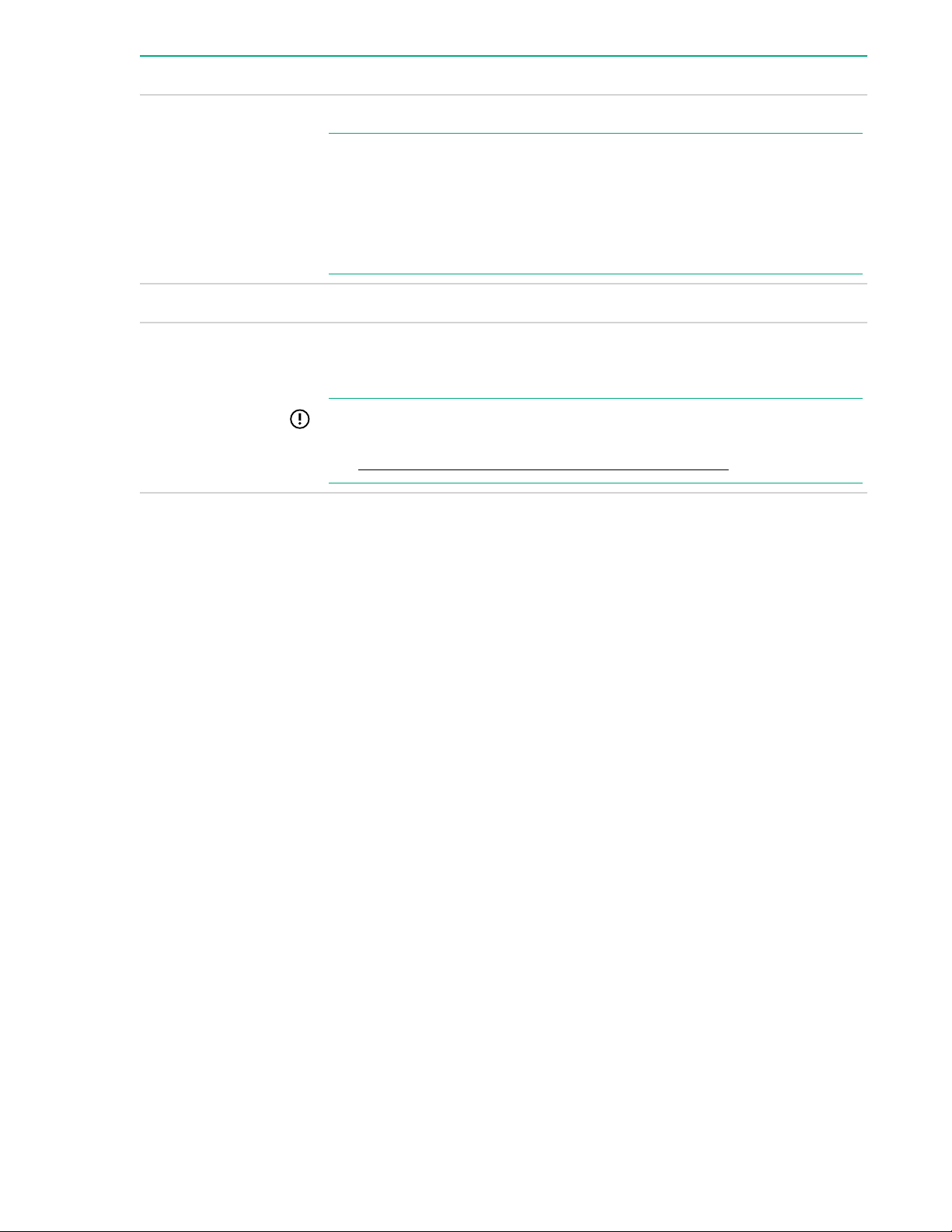
Internal components
Figure 1: Internal components
• Fans
• Processors
• DIMM expansion boards
Internal components 13
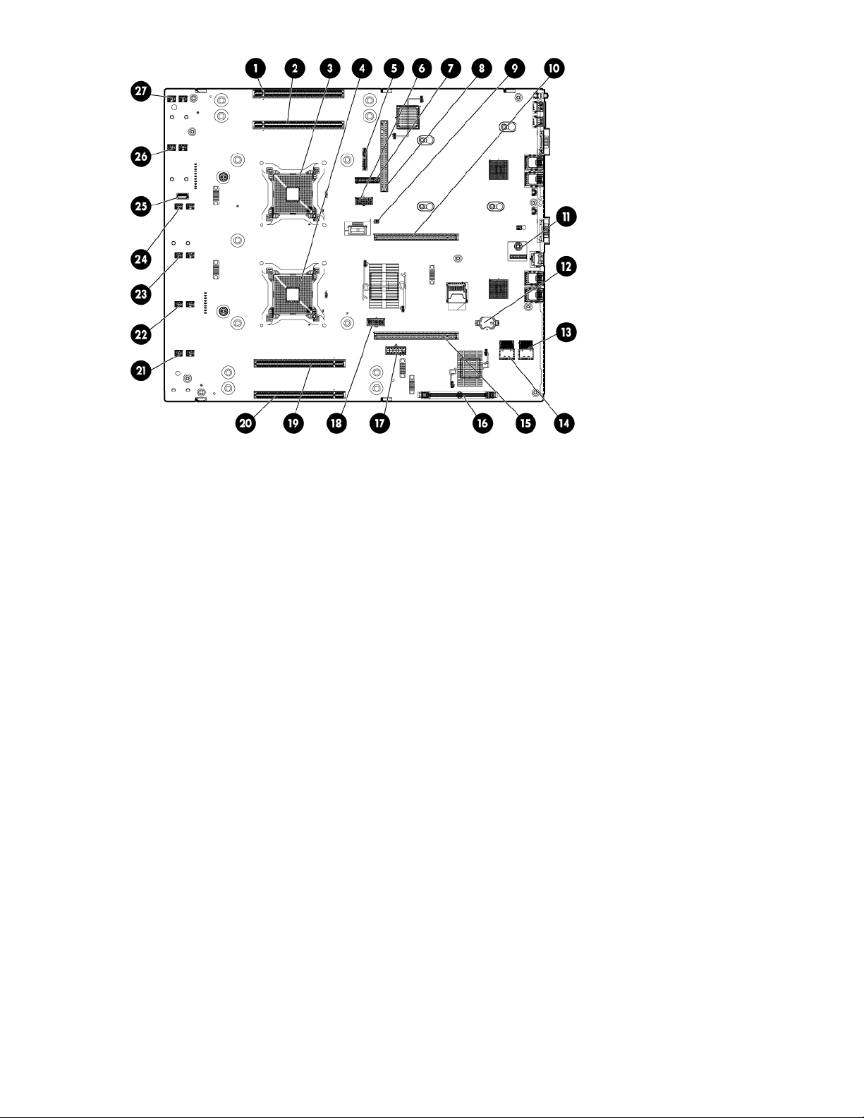
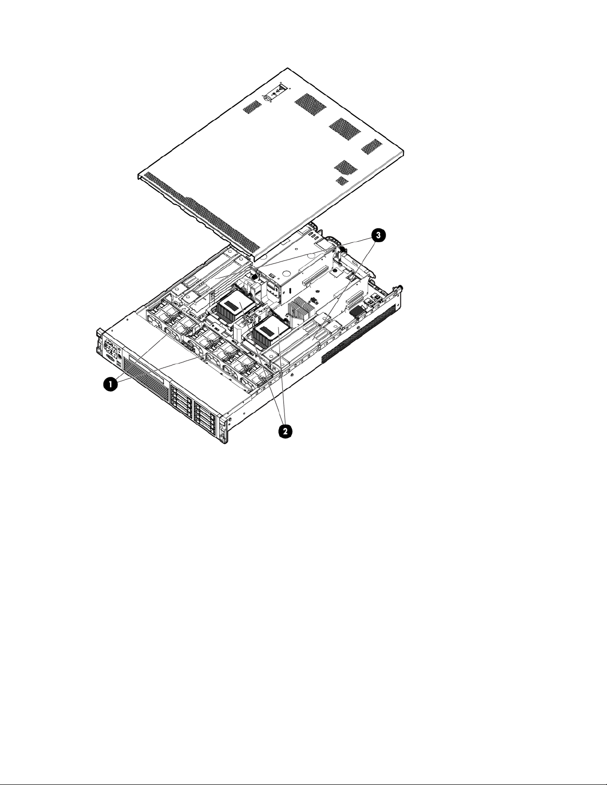
Figure 2: System board components
• Memory expansion board connector 1
• Memory expansion board connector 2
• Processor socket 0
• Processor socket 1
• SATA optical drive connector
• CPU 0 power connector
• Front I/O connector
• Power supply backplane connector
• Intrusion switch connector
• Primary riser connector
• TPM connector
• System battery
• SAS B connector
• SAS A connector
• Secondary riser connector
• SAS cache module connector
• SAS power connector
• CPU 1 power connector
• Memory expansion board connector 3
14 Overview
• Memory expansion board connector 4
• Fan 6 connector
• Fan 5 connector
• Fan 4 connector
• Fan 3 connector
• Internal USB connector
• Fan 2 connector
• Fan 1 connector
Figure 3: Internal USB location
I/O subsystem
The I/O subsystem consists of the core I/O and two optional I/O riser boards. Wake-on-LAN is not
enabled on any PCIe Public slots. The server does not support PCI Hot Plug (PHP).
The standard I/O Riser supports one full-height, full-length PCIe x8 and two full-height, half-length PCIe
x4 add-in cards. The second riser option supports one full-height, full-length PCIe x8, and one full-height,
half-length PCIe x8 add-in cards.
NOTE:
All PCIe x8 slots are electrically connected as x8 slots but are physically loaded with x16
connectors.
The secondary I/O riser position can either be a riser that supports one full-height, full-length PCIe x8 and
two low-profile PCIe x4 add-in cards or a riser that supports one full-height, full-length PCIe x8 and one
low profile PCIe x8.
RAID support
The following levels of RAID support are offered:
• Zero memory
I/O subsystem 15

◦ RAID 0, 1, 10
◦ Maximum 8 drives, 2 logical volumes
◦ No cache or super capacitor needed. Performance improved with cache.
NOTE:
To use all 8 disks with the zero memory option, the following RAID configurations are
supported:
– RAID 0: 1 or 2 LUNs striped with up to 8 disks
– RAID 10: 1 or 2 LUNs striped and mirrored with even number of up to 8 disks
– RAID 1: 1 LUN using 2 mirrored disks, and one additional LUN in RAID 0 or 10
Example configurations of eight disks with zero memory
– LUN 1: RAID 1 bays 1 and 2
– LUN 2: RAID 0 bays 3, 4, 5, 6, and 7
– Hot Spare: bay 8
– LUN 1: RAID 10 bays 1, 2, 3, and 4
– LUN 2: RAID 10 bays 5, 6, 7, and 8
– LUN 1: RAID 0 bays 1, 2, and 3
– LUN 2: RAID 10 bays 5, 6, 7, and 8
– Hot Spare: bay 4
• Full feature
◦ RAID 0, 10, 5
◦ Cache needed and installing it automatically enables the full feature firmware stack. Super
capacitor is optional.
• Advanced pack
◦ RAID 6, 50, 60
◦ Cache needed. Advanced Pack license must be entered to enable. Super capacitor is required.
To enable Advanced Pack licensing, see Adding a RAID Advanced Pack license key on page 185.
Controls and ports
16 Controls and ports
Front panel controls and ports
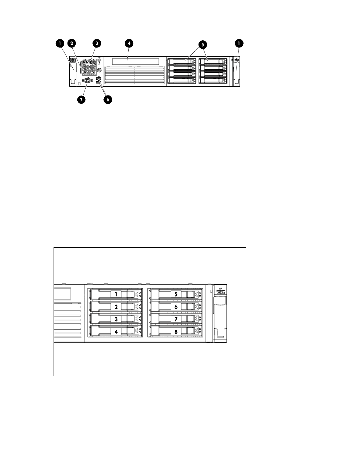
Figure 4: Front panel components
1. Quick release levers
2. iLO 3 information pull tab
3. SID
4. Optical drive bay
5. Hard drive bays
6. USB connectors
7. Video connector
Storage and media devices
The server supports up to eight hot-plug SAS HDDs, and one optical (SATA DVD+RW) drive, with LEDs
that indicate activity and device statuses.
Figure 5: SAS device numbers
Front panel controls and ports 17

Rear panel controls and ports
The server rear panel includes communication ports, I/O ports, USB ports, AC power connectors, and the
locator LED and button. LEDs located on the rear panel of the server signal the operational status of the
rear panel components.
Figure 6: Rear panel components
1. PCI 5
2. PCI 6
3. PCI 4
4. PCI 2
5. PCI 3
6. PCI 1
7. Power supply 2
8. Power supply 2 LED
9. Power supply 2 power connector
10. Power supply 1
11. Power supply 1 LED
12. Power supply 1 power connector
13. UID LED button
14. USB connectors (2)
15. Video connector
16. NIC 1 connector
17. NIC 2 connector
18. iLO 3 physical presence pinhole button
19. Serial connector
20. iLO 3 connector
18 Rear panel controls and ports

21. NIC 3 connector
22. NIC 4 connector
23. NIC link LED
24. NIC activity LED
Overview 19
Site preparation
For information on general computer room site preparation, see the HPE Generalized Site Preparation
Guide on the Hewlett Packard Enterprise website:
http://www.hpe.com/info/Integrity_Servers-docs
IMPORTANT:
To avoid hardware damage, allow the thermal mass of the product to equalize to the temperature
and humidity of the installation facility after removing the shipping materials. A minimum of one hour
per 10° C (50° F) of temperature difference between the shipping facility and installation facility is
required.
Server dimensions and weight
Table 2: Rack or pedestal-mounted server dimensions
Dimensions and weight Value
Data center server dimensions
Depth 69.2 cm (27.25 in)
Width 48.3 cm (19 in)
Height 8.9 cm (3.5 in)
Weight Maximum configuration – 30 kg (66 lb)
Rack unit 2U
Grounding
The site building must provide a safety ground/protective earth for each AC service entrance to all
cabinets.
Install a PE conductor that is identical in size, insulation material, and thickness to the branch-circuit
supply conductors. The PE conductor must be green with yellow stripes. The earthing conductor is to be
connected from the unit to the building installation earth or, if supplied by a separately derived system, at
the supply transformer or motor-generator set grounding point.
Server electrical specifications
System power specifications
Available power (output) is the maximum DC power that the power supply can supply to the system.
Maximum input power is what the power supply requires from the AC line to deliver that maximum DC
output (given worst case efficiency and maximum loading).
Maximum input current is the worst case/highest current given the lowest input voltage and the maximum
input power.
20 Site preparation

Table 3: System power specifications
Parameter
Input voltage 100 V AC 110 - 120 V AC 200 - 240 V AC
Input current (maximum) 9.3 A 9.5 A 6.6 A
Input frequency 47 to 63 Hz 47 to 53 Hz 57 to 63 Hz
Power supply maximum output power 800 W (MAX)
If an overload triggers the power supply overload protection, the system is immediately powered off. To
reset the power supply unit:
Procedure
1. Disconnect the power cord.
2. Determine what caused the overload by contacting a Hewlett Packard Enterprise support
3. Reconnect the power cord.
4. Reboot the system.
When you use the front panel power button to turn off the server, power consumption falls below the low
power consumption, but does not reach zero. To reach zero power consumption in "off" mode, either
unplug the server or use a power block with a switch.
+12V /66.7A MAX
+12VSB /2.5A
MAX
representative.
NOTE:
If an overload occurs twice, an undetected short circuit exists.
900 W (MAX)
+12V /75A MAX
+12VSB /2.5A
MAX
1200 W (MAX)
+12V /100A MAX
+12VSB /2.5A
MAX
Power consumption and cooling
The power consumptions listed in Standard configuration power consumption are valid for a standard
configuration as shipped.
All information in this section is based on primary power consumptions with one power supply installed.
Table 4: Standard configuration power consumption
Standard configuration Power consumption
One 1.46 GHz quad-core processor, 4 GB
memory, one 1200 W power supply, and one SAS
disk drive
360 W (maximum) 1228 Btu/h (maximum)
Power consumption and cooling 21

Table 5: Additional component power consumption
Additional component Power consumption
Processor 130 W 443.6 Btu/h
SAS disk drive (with I/O access) 23 W 78.4 Btu/h
SAS disk (idle) 16 W 54.5 Btu/h
PCIe card 10 to 25 W 34.12 Btu/h to 85.30 Btu/h
Server physical and environmental specifications
Operating temperature and humidity ranges might vary, depending on the installed mass storage devices.
High humidity levels can cause improper disk operation. Low humidity levels can aggravate static
electricity issues and cause excessive wear of the disk surface.
NOTE:
De-rate maximum dry bulb temperature 1°/300 m (1000 ft) above 900 m (3000 ft).
Table 6: Environmental specifications (system processing unit with hard disk)
Parameter Value
Data Center Server Office Friendly Server
Operating temperature (up to 1524 m/5000 ft) +5° C to +35° C (+41° F to +95° F)
Non-operating temperature - 40° C to +70° C (40° F to 158° F)
Over-temperature shutdown +38° C (+100° F)
Operating humidity 15% to 80% RH noncondensing
Non-operating humidity 8% to 90% RH at 65° C noncondensing
Acoustic Noise Emission (ISO 9296)
Sound Power
Level
Sound Pressure Level LpAm = 52.7 dB LpAm = 42.4 dB
Altitude
Operating altitude 0 to 3000 m (10,000 ft) maximum
Maximum configuration (disk
active)
LwAd = 7.0 B LwAd = 6.0 B
Non-operating altitude 0 to 4,600 m (15,000 ft) maximum
22 Server physical and environmental specifications

Unpacking and inspecting the server
This section describes pre installation procedures. Ensure that you have adequately prepared your
environment for installing the new server, received the components that you ordered, and verified that the
server and the containers are in good condition after shipment.
Verifying site preparation
• Gather LAN information. The MAC addresses for the iLO 3 MP LAN and the system LAN are located
on the iLO Network Information Tag.
• Establish a method to connect to the server console.
• Verify electrical requirements. Ensure that grounding specifications and power requirements are met.
• Validate server physical space requirements.
• Confirm environmental requirements.
For server-specific information on electrical, physical space, and environmental requirements, see the site
prep guide. For general site preparation information, see the HPE Generalized Site Preparation Guide
on the Hewlett Packard Enterprise website.
Inspecting the shipping containers for damage
Under normal shipping conditions, Hewlett Packard Enterprise shipping containers protect the contents.
After the equipment arrives, carefully inspect each carton for signs of shipping damage. Shipping damage
constitutes moderate to severe damage, such as punctures in the corrugated carton, crushed boxes, or
large dents. Normal wear or slight damage to the carton is not considered shipping damage. If you find
shipping damage to the carton, immediately contact your Hewlett Packard Enterprise customer service
representative.
Unpacking the server
Procedure
1. Follow the instructions printed on the outside top flap of the carton to remove the banding and the
outer carton from the server pallet.
2. Remove all inner accessory cartons and the top foam cushions, leaving only the server.
IMPORTANT:
Inspect each carton for shipping damage as you unpack the server.
Verifying the inventory
The sales order packing slip lists all the equipment shipped from Hewlett Packard Enterprise. Use this
packing slip to verify that all equipment has arrived.
NOTE:
To identify each item by part number, see the sales order packing slip.
Unpacking and inspecting the server 23

Returning damaged equipment
If the equipment is damaged, immediately contact your Hewlett Packard Enterprise customer service
representative. The service representative initiates appropriate action through the transport carrier or the
factory and assists you in returning the equipment.
Unloading the server with a lifter
WARNING:
Use caution when using a lifter. Because of the weight of the server, to avoid injury, you must center
the server on the lifter forks before lifting it off the pallet.
NOTE:
Hewlett Packard Enterprise recommends that you follow your local guidelines when lifting
equipment.
Procedure
1. Unpack the server.
2. Unroll the bottom corrugated tray corresponding to the side on which the lifter is to be placed, and then
slide the server as close to that edge of the pallet as possible.
3. Break off any foam packaging that can prevent the lifter from being fully inserted under the server. Do
not remove the foam packaging from the corners of the server. This foam is required to elevate the
server and to enable the forks of the lifter to be placed under the server.
4. Insert the lifter forks under the server.
5. Carefully roll the lifter forward until it is fully positioned against the side of the server.
6. Slowly raise the server off the pallet until it clears the pallet cushions.
7. Carefully roll the lifter and server away from the pallet. Do not raise the server any higher than
necessary when moving it over to the rack.
24 Returning damaged equipment

Installing the server
Safety information
Follow the instructions carefully to prevent injury and equipment damage when performing removal and
replacement procedures. Voltage might be present within the server. Many assemblies are sensitive to
damage by ESD.
Follow the safety considerations listed to ensure safe handling of components, to prevent injury, and to
prevent damage to the server:
• If installing a hot-swappable or hot-pluggable component when power is applied (fans are running),
reinstall the server cover immediately to prevent overheating.
If installing a hot-pluggable component, complete the required software intervention prior to removing
the component.
• If installing an assembly that is neither hot-swappable nor hot-pluggable, disconnect the power cable
from the external server power receptacle before starting the installation.
WARNING:
Ensure that the system is powered off and all power sources are disconnected from the server
before removing or installing server hardware (unless you are removing or installing a hotswappable or hot-pluggable component). Voltage is present at various locations within the server
whenever an AC power source is connected. This voltage is present even when the main power
switch is off. Failure to observe this warning might result in personal injury or equipment
damage.
• Do not wear loose clothing that might snag or catch on the server or on other components.
• Do not wear clothing subject to static charge buildup, such as wool or synthetic materials
• If installing an internal assembly, wear an antistatic wrist strap and use a grounding mat, such as those
included in the Electrically Conductive Field Service Grounding Kit.
• Handle accessory boards and components by the edges only. Do not touch any metal edge
connectors or any electrical components on accessory boards.
Preventing electrostatic discharge
To prevent damaging the system, be aware of the precautions you need to follow when setting up the
system or handling parts. A discharge of static electricity from a finger or other conductor might damage
system boards or other static-sensitive devices. This type of damage might reduce the life expectancy of
the device.
To prevent electrostatic damage:
• Avoid hand contact by transporting and storing products in static-safe containers.
• Keep electrostatic-sensitive parts in their containers until they arrive at static-free workstations.
• Place parts on a grounded surface before removing them from their containers.
Installing the server 25

• Avoid touching pins, leads, or circuitry.
• Always be properly grounded when touching a static-sensitive component or assembly.
Installation sequence and checklist
Step Description Completed
1 Perform site preparation (see Site preparation on page 20).
2 Install the server into a rack or pedestal.
3 Connect cables to the server.
a. Connect the AC input power cable.
b. Connect LAN core I/O cable.
c. Connect the iLO 3 MP LAN cable.
4 Connect and set up the console for access.
5 Power on the server.
6 From iLO MP, access UEFI.
7 Boot the operating system.
8 Using Smart Update Manager, download the latest firmware.
Installing the server into a rack or pedestal
Rack installation
Hewlett Packard Enterprise rack
Hewlett Packard Enterprise servers that are installed into racks are shipped with equipment-mounting
slides. The HPE 2U Quick Deploy Rail System Installation Instructions for HPE Products ships with each
set of slides. Follow the steps in this installation guide to determine where and how to install the server
into the rack.
For more information on rack deployment, stabilization and transportation, see the 10000 Series G2 Rack
Best Practices Guide.
http://www.hpe.com/info/rackandpower
Non-Hewlett Packard Enterprise rack
For information on installing a HPE Integrity rx2800 i2 server in a third party rack, see the QuickSpecs
located on the rx2800 i2 server product page.
http://www.hpe.com
26 Installation sequence and checklist
Search for "Integrity rx2800 i2 server" and click the product link for more information and
QuickSpecs.
Pedestal kit installation
If you order the rackless configuration option, the server ships with a pedestal mount. The pedestal mount
is packaged in a separate carton that is attached to the server carton.
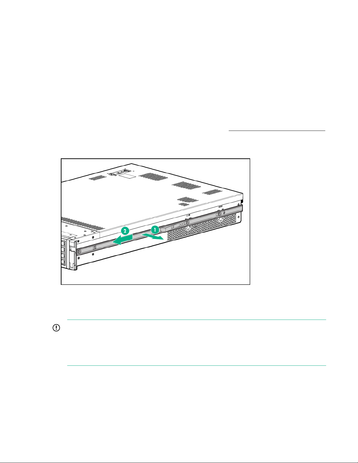
Remove the rails from the server
I If your server has rails when you receive it, you need to remove the rails before mounting it in the
pedestal kit. To remove the component:
Procedure
1. Slightly pull the rail lock away from the rail to unlock the rail. See Removing the rails from the server
2. Slide the rail toward the front of the server to disengage the rail from the posts on the server.
3. Repeat these steps for the rail on the other side of the server.
Figure 7: Removing the rails from the server
Attaching the pedestal kit top and bottom
IMPORTANT:
In this document the server top, bottom, right and left refer to the server as faced from the front with
the server in a horizontal orientation. The pedestal kit components are referred to by the final
position with the server in a vertical orientation. For example, the pedestal kit bottom attaches to the
server right side
Pedestal kit installation 27
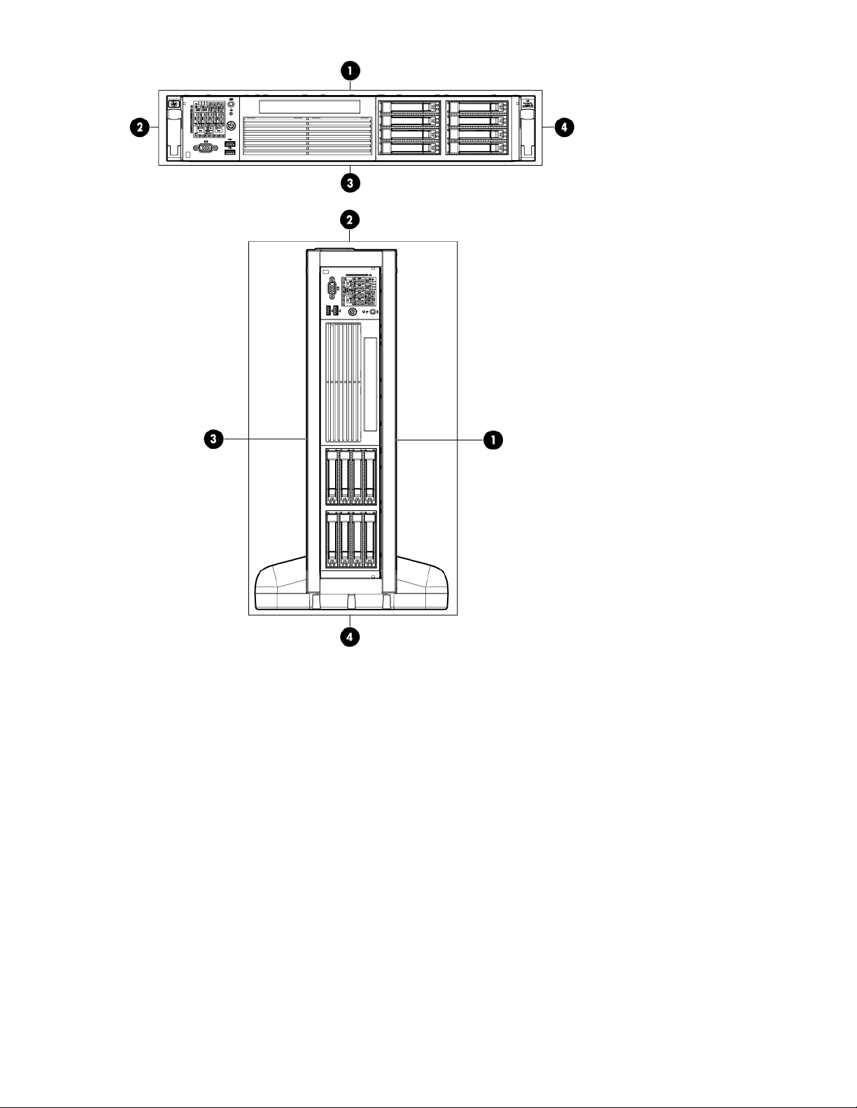
Figure 8: Front of server
1. Server top/pedestal right
2. Server left/pedestal top
3. Server bottom/pedestal left
4. Server right/pedestal bottom
The pedestal kit bottom attaches to the right side of the server when the server is in the horizontal
position. The pedestal kit top attaches to the left side of the server when in the server is in the horizontal
position. The pedestal bottom can be distinguished from the pedestal top by the pedestal feet slots.
28 Installing the server
Procedure
NOTE:
The bottom piece of the pedestal is taller than the server, so try to position the server so the right side (in the
horizontal position) of the server hangs off the edge of the work surface by a few inches to allow the bottom
piece to be attached to the server chassis. If that is not possible, then raise up the server approximately
three inches from the work surface to enable the pedestal kit bottom piece to be attached to the server right
side.
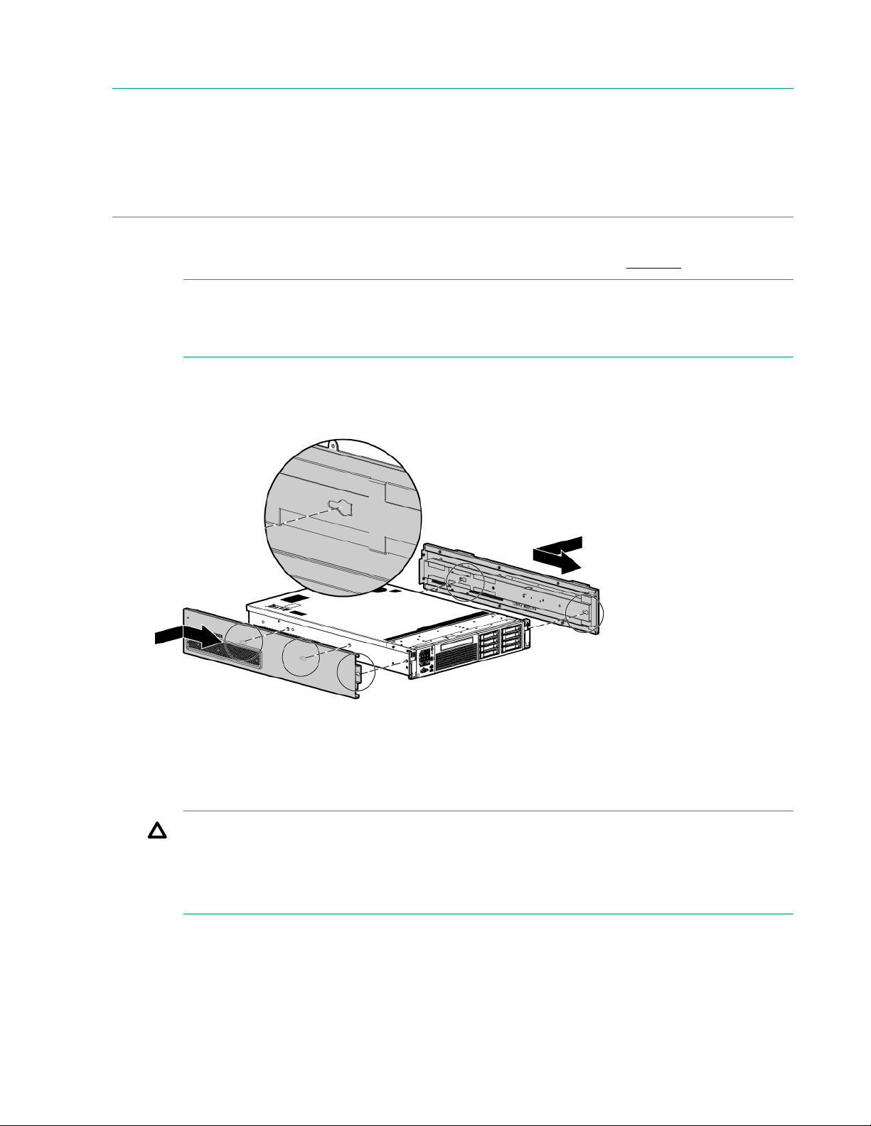
To attach the components.
1. Align the holes in the pedestal component with the posts on the server. See Figure 9.
NOTE:
One of the holes in the pedestal component contains the locking mechanism. This makes the
hole appear partially blocked.
2. Hold the pedestal component flush against the server.
3. Slide the pedestal component forward until it locks into place.
Figure 9: Installing the pedestal bottom piece
4. Stand the server up on the bottom piece of the pedestal kit that was just installed so the server is in
the vertical position.
CAUTION:
The server is heavy. Be careful when lifting it to the vertical position.
Without the feet installed, the server might tip over easily. Be careful when working near the
server to avoid tipping it over.
5. Align the holes in the pedestal top piece with the posts on the server
Installing the server 29

NOTE:
One of the holes in the pedestal component contains the locking mechanism. This makes the
hole appear partially blocked.
6. Hold the pedestal top piece flush against the server.
7. Slide the pedestal top piece forward until it locks into place.
8. The top and bottom pedestal kit pieces are now in place.
Attaching the bezel cover
To attach the bezel cover:
Procedure
1. Attach the bezel cover to the front of the server starting from the bottom of the pedestal kit.
2. Push the bezel cover into place against the pedestal kit top piece until the tabs on the bezel cover
snap into place.
Figure 10: Attaching the bezel Cover
Attaching the pedestal kit side pieces
The pedestal kit right side piece attaches to the top of the server. The top cover of the server might have
ventilation holes in it to enable proper air flow and cooling. The right side piece of the pedestal kit also
has ventilation holes in it to enable the proper cooling and air flow. Follow these steps to attach the
pedestal kit right side piece.
30 Attaching the bezel cover
 Loading...