

Page 1

HP Integrity Servers with Microsoft®
Windows Server™ 2003
Smart Setup Guide
HP Part Number: 5992-0964
Published: October 2007
Page 2

© Copyright 2007 Hewlett-Packard Development Company, L.P.
Legal Notices
Confidential computer software. Valid license from HP required for possession, use or copying. Consistent withFAR 12.211 and 12.212, Commercial
Computer Software, Computer Software Documentation, and Technical Data for Commercial Items are licensed to the U.S. Government under
vendor's standard commercial license.
The information contained herein is subject to changewithoutnotice.The only warranties for HP products and services are set forth in the express
warranty statements accompanying such products and services. Nothing herein should be construed as constituting an additional warranty. HP
shall not be liable for technical or editorial errors or omissions contained herein.
Microsoft and Windows are U.S. registered trademarks of Microsoft Corporation.
Intel and Itanium are registered trademarks of Intel Corporation or its subsidiaries in the United States and other countries.
Java is a U.S. trademark of Sun Microsystems, Inc.
UNIX is a registered trademark of The Open Group.
Page 3

Table of Contents
About This Document.......................................................................................................11
Intended Audience................................................................................................................................11
New and Changed Information in This Edition...................................................................................11
Document Organization.......................................................................................................................11
Typographic Conventions.....................................................................................................................11
Related Information..............................................................................................................................12
Publishing History................................................................................................................................13
HP Encourages Your Comments..........................................................................................................13
1 Preparing for the installation.......................................................................................15
Choosing an installation method..........................................................................................................15
Ensuring platform compatibility..........................................................................................................16
Check hardware compatibility........................................................................................................16
Back up existing data.......................................................................................................................17
Choosing an installation environment.................................................................................................17
Choosing the Installation media......................................................................................................18
Using the Microsoft OS media.........................................................................................................18
Using the HP Reinstallation media.................................................................................................18
Locating the Microsoft Certificate of Authenticity...............................................................................18
Setting up a console..............................................................................................................................22
Set up a headless console.................................................................................................................22
Set up the headless console using a null modem cable.............................................................22
Set up the headless console using a LAN..................................................................................23
Set up the headless console using a Remote Serial Console (rx2660, rx3600, rx6600, BL860c,
and BL870c only)........................................................................................................................23
Set up a GUI console........................................................................................................................23
Set up an Integrated Remote Console (rx2660, rx3600, rx6600, BL860c, and BL870c only)............25
Set up a Virtual Media (vMedia) drive......................................................................................25
Setting up PXE/RIS................................................................................................................................26
Set up a RIS server...........................................................................................................................27
Install RIS...................................................................................................................................28
Configure RIS.............................................................................................................................28
Authorize a RIS server in Active Directory................................................................................29
Use the Client Installation Wizard.............................................................................................29
Preparing the server hardware.............................................................................................................30
Set up the boot drive........................................................................................................................30
Boot to EFI.......................................................................................................................................30
Locate the DVD/CD drive...............................................................................................................31
Set ACPI flag to windows (cell-based servers only).......................................................................32
Set cell local memory to 100% (cell-based servers only).................................................................32
Specify NIC for a network boot.......................................................................................................32
2 Installing the OS...........................................................................................................35
Installing from a headless console........................................................................................................35
Run EBSU........................................................................................................................................36
Run Windows Setup........................................................................................................................38
Enter the product key......................................................................................................................39
Installing from a GUI console...............................................................................................................39
Run EBSU........................................................................................................................................39
Table of Contents 3
Page 4

Run Windows Setup........................................................................................................................42
Specify server settings.....................................................................................................................42
Installing from PXE...............................................................................................................................43
Reinstalling from a headless console....................................................................................................43
Load the system image....................................................................................................................44
Specify server settings.....................................................................................................................45
Reinstalling from a GUI console...........................................................................................................46
Load the system image....................................................................................................................46
Specify server settings.....................................................................................................................47
Applying OS updates............................................................................................................................47
Enabling Windows components...........................................................................................................48
Install TCP/IP...................................................................................................................................48
Install SNMP....................................................................................................................................48
Configure SNMP.............................................................................................................................49
Set IP addresses from a headless console........................................................................................49
Set up and run a Remote Desktop Connection...............................................................................49
Updating firmware, drivers, and software...........................................................................................50
Enable greater than 256 interrupts (cell-based servers only)..........................................................50
Update firmware.............................................................................................................................51
Update device drivers.....................................................................................................................51
Install the Integrity Support Pack (ISP)...........................................................................................52
Install updates from the web...........................................................................................................53
Register for HP support notifications..............................................................................................53
Register for Microsoft security notifications...................................................................................53
Register for Microsoft Windows Update.........................................................................................53
Miscellaneous installation issues..........................................................................................................53
Using Integrated Remote Console to install Windows on rx2660, rx3600, rx6600, BL860c, and
BL870c servers.................................................................................................................................53
Installing a Windows guest on an HP Integrity Virtual Machine host...........................................54
Enabling hyperthreading on HP Integrity servers..........................................................................55
Enable hyperthreading using EFI..............................................................................................55
Enable hyperthreading using Partition Manager......................................................................56
3 Installing the Management Tools................................................................................57
Installing System Management Homepage..........................................................................................57
Configure SMH after Support Pack installation..............................................................................57
Install SMH separately....................................................................................................................57
Initializing SMH .............................................................................................................................59
Installing the management agents........................................................................................................59
Configure management agents after Support Pack installation.....................................................60
Install management agents from Smart Setup media.....................................................................60
Activating and configuring agents..................................................................................................60
Activating agents........................................................................................................................60
Configuring the event notifier....................................................................................................61
Setting the agent SNMP data collection interval.......................................................................63
Monitoring server processes......................................................................................................64
Sending SNMP traps to management applications via IP.........................................................65
Installing partition management tools..................................................................................................66
Install nPartition Commands Bundle from the Smart Setup media...............................................67
Install Partition Manager Bundle from the Smart Setup media......................................................67
Verifying the installation.................................................................................................................68
Verify nPartition commands......................................................................................................68
Verify Partition Manager installation.........................................................................................68
4 Table of Contents
Page 5

4 Performing hot-plug operations...................................................................................71
Before you begin...................................................................................................................................71
Adding a PCI card................................................................................................................................72
Hardware interface for all HP Integrity servers except Superdome...............................................72
Hardware interface for Superdome servers....................................................................................73
Software interface............................................................................................................................74
Removing a PCI card............................................................................................................................74
Software interface for all HP Integrity servers except Superdome.................................................74
Software interface for Superdome servers......................................................................................74
Hardware interface for all HP Integrity servers except Superdome...............................................74
Hardware interface for Superdome servers....................................................................................75
A Preparing the server for Microsoft SQL Server 2005..............................................77
SQL Server 2005 installation.................................................................................................................77
Installing SQL Server from the command prompt..........................................................................77
Installing SQL Server from the GUI................................................................................................78
B EFI Utilities.....................................................................................................................81
Introduction to EFI................................................................................................................................81
EFI Boot Manager............................................................................................................................81
EFI Shell...........................................................................................................................................81
Common EFI Shell commands........................................................................................................82
EFI-Based Setup Utility...................................................................................................................85
Creating a new boot file using the EFI Shell.........................................................................................86
Verify successful boot file creation..................................................................................................87
C Management processor and Special Administration Console...............................89
Management processor.........................................................................................................................89
Accessing the MP.............................................................................................................................89
MP Commands................................................................................................................................89
Special Administration Console...........................................................................................................94
SAC Channel Management Commands.........................................................................................96
Table of Contents 5
Page 6

6
Page 7

List of Figures
1-1 Headless console configurations...................................................................................................22
1-2 GUI console configuration............................................................................................................24
1-3 PXE/RIS configuration...................................................................................................................27
2-1 Enter EBSU....................................................................................................................................36
2-2 Select Express Setup......................................................................................................................36
2-3 Update firmware...........................................................................................................................37
2-4 Partition disk.................................................................................................................................37
2-5 Install diagnostic tools...................................................................................................................38
2-6 Insert the Microsoft Windows Server 2003 CD.............................................................................38
2-7 Enter EBSU....................................................................................................................................39
2-8 Select Express Setup......................................................................................................................40
2-9 Update firmware...........................................................................................................................40
2-10 Partition disk.................................................................................................................................41
2-11 Install diagnostic tools...................................................................................................................41
2-12 Insert the Microsoft Windows Server 2003 CD.............................................................................42
2-13 Enabling hyperthreading in the Partition Manager......................................................................56
3-1 HP System Management Homepage for Windows .....................................................................57
3-2 HP Insight Management Agents for Windows Server 2003 on Itanium-based systems..............60
3-3 Services tab screen.........................................................................................................................61
3-4 Welcome message..........................................................................................................................61
3-5 Mail (SMTP) server information...................................................................................................62
3-6 Event recipients information.........................................................................................................62
3-7 Adding a new user........................................................................................................................62
3-8 Event selection window................................................................................................................63
3-9 SNMP Settings tab.........................................................................................................................64
3-10 Process Monitor tab.......................................................................................................................64
3-11 Component Services window.......................................................................................................65
3-12 SNMP traps tab.............................................................................................................................66
3-13 SNMP service configuration..........................................................................................................66
B-1 EFI Boot Manager..........................................................................................................................81
7
Page 8

8
Page 9

List of Tables
1-1 Installation matrix.........................................................................................................................17
1-2 Locating the Microsoft COA.........................................................................................................19
1-3 Graphics support on server models..............................................................................................24
1-4 EFI device mapping fields.............................................................................................................31
2-1 Integrity servers supporting PXE/RIS installations.......................................................................43
4-1 PCI cards that do not support hot-plug addition..........................................................................72
B-1 EFI Shell Commands and Descriptions.........................................................................................82
C-1 Channel Management commands.................................................................................................96
9
Page 10

10
Page 11

About This Document
This document describes how to install and configure the operating system and HP software on
HP Integrity servers running Windows Server 2003.
The document printing date and part number indicate the document’s current edition. The
printing date changes when a new edition is printed. Minor changes may be made at reprint
without changing the printing date. The document part number changes when extensive changes
are made.
Document updates may be issued between editions to correct errors or document product changes.
To ensure that you receive the updated or new editions, you should subscribe to the appropriate
product support service. See your HP sales representative for details.
The latest version of this document can be found online at http://www.docs.hp.com.
Intended Audience
This document is intended for system administrators and HP support personnel responsible for
installing, configuring, and managing HP Integrity servers.
This document is not a tutorial.
New and Changed Information in This Edition
This document includes the following changes since its last release:
• Added “About This Document” section
• Added introductory/overview content at the beginning of Chapters 1 and 2
• Added additional steps to “Specify server settings” procedures in Chapter 2
• Removed references to Intelligent Networking Pack licensing (INP functionality was
integrated into the core product)
Document Organization
This document is organized as follows:
Chapter 1
Chapter 3
Chapter 4
Appendix A
Appendix B
Appendix C
Chapter 1 “Preparing for the installation”. Describes the steps to prepare the server for
installation of the operating system, SmartSetup, and management software.
Chapter 2 “Installing the OS”. Describes how to install the operating system software.Chapter 2
Chapter 3 “Installing the Management Tools”. Describes how to install the server
management software.
Chapter 4 “Performing hot-plug operations”. Describes how to add and remove server
hardware such as network interface cards (NICs) or RAID cards.
Appendix A “Preparing the server for Microsoft SQL Server 2005”. Describes how to
configure and install Microsoft SQL Server 2005.
Appendix B “EFI Utilities”. Describes the server's Extensible Firmware Interface (EFI) and
EFI-Based Setup Utility (EBSU).
Appendix C “Management processor and Special Administration Console”. Describes
the server's management processor (MP) and Special Administration Console (SAC).
These are tools for monitoring the operating system installation and administering the
server from a headless console.
Typographic Conventions
This document uses the following typographical conventions:
Intended Audience 11
Page 12

WARNING A warning calls attention to important information that if not understood
or followed will result in personal injury or nonrecoverable system
problems.
CAUTION A caution calls attention to important information that if not understood
or followed will result in data loss, data corruption, or damage to
hardware or software.
IMPORTANT This alert provides essential information to explain a concept or to
complete a task
NOTE A note contains additional information to emphasize or supplement
important points of the main text.
KeyCap
Computer output
User input
Command
Ctrl+x A key sequence. A sequence such as Ctrl+x indicates that you must hold
[] The contents are optional in command line syntax. If the contents are a
{} The contents are required in command line syntax. If the contents are a
... The preceding element can be repeated an arbitrary number of times.
Indicates the continuation of a code example.
| Separates items in a list of choices.
The name of a keyboard key or graphical interface item (such as buttons,
tabs, and menu items). Note that Return and Enter both refer to the
same key.
Text displayed by the computer.
Commands and other text that you type.
A command name or qualified command phrase.
down the key labeled Ctrl while you press another key or mouse button.
list separated by |, you must choose one of the items.
list separated by |, you must choose one of the items.
Related Information
You can find more information about HP Integrity servers, server management, and software
in the following locations:
• For an overview of the HP Integrity server family: http://www.hp.com/go/integrity
• For other documents supporting Windows Server 2003 on HP Integrity Servers (see the
section titled “Windows 64–bit on HP Integrity Servers”):
http://docs.hp.com/en/windows.html
• For technical support resources (drivers, patches, upgrades, migration issues, to sign up for
alerts, etc.):
http://h20000.www2.hp.com/bizsupport/TechSupport/Product.jsp?prodTypeId=15351&prodCatId=321933
• For information about HP Integrity Virtual Machines (Integrity VM):
http://h71028.www7.hp.com/enterprise/cache/262803-0-0-0-121.html
12
Page 13

Publishing History
The publishing history below identifies the edition dates of this manual. Updates are made to
this publication on an unscheduled, as needed, basis. The updates will consist of a complete
replacement manual and pertinent online or CD documentation.
Manufacturing Part
Number
5992-0926
Supported Operating
Systems
Server 2003 for
Itanium-based
Systems, 64–bit
HP Encourages Your Comments
HP encourages your comments concerning this document. We are committed to providing
documentation that meets your needs. Send any errors found, suggestions for improvement, or
compliments to:
feedback@fc.hp.com
Please include the document title, manufacturing part number, and any comment, error found,
or suggestion for improvement you have concerning this document.
Supported SmartSetup
Version
Version 5.2Microsoft Windows
Publication DateSupported Products
(Servers)
September, 2007BL860c, BL870c,
rx1620, rx2620,
rx2660, rx3600,
rx4640, rx6600,
rx7620, rx7640,
rx8620, rx8640,
Superdome,
Superdome/sx2000
Publishing History 13
Page 14

14
Page 15

1 Preparing for the installation
Installing Microsoft® Windows® Server 2003 for Itanium®-based systems on an HP Integrity
server involves preparing the hardware for operating system (OS) installation, loading the OS,
and updating the system with the latest OS patches. This chapter helps you plan the installation
based on the server model, the OS edition, the source of the OS media, and your network
environment. Subsequent chapters guide you through the installation process.
NOTE: HP Integrity servers must run Windows Server 2003 with either Service Pack 1 (SP1)
or Service Pack 2 (SP2). If your operating system is already installed and you are running an
earlier version of Windows Server 2003, you must upgrade your operating system to SP1 or SP2.
When updating to SP1 or SP2, perform the update in the following order:
1. Install the latest HP Integrity Support Pack.
2. Reboot the machine.
3. Install the desired Service Pack.
4. Reboot the machine again.
5. Use the Windows Update Service to ensure that you have the latest Microsoft updates.
If the Windows Server 2003 operating system has already been installed on your system, or if it
was pre-installed by HP before your system was delivered, you do not have to perform any of
the steps described in this chapter (Chapter 1 “Preparing for the installation”) or in Chapter 2
(Chapter 2 “Installing the OS”). You can proceed directly to Chapter 3 (Chapter 3 “Installing the
Management Tools”) and begin the installation of your management tools software.
If your Windows Server 2003 operating system is not already installed, or if you wish to reinstall
it for some reason, or if you wish to migrate to Windows Server 2003 from another operating
system, you will need to perform one or more of the following steps described in this chapter,
in the following order:
• Choose an installation method
• Check hardware compatibility
• Back up your existing data
• Choose your installation environment and media
• Locate your Microsoft Certificate of Authenticity
• Choose an installation option:
— Local installation choices (pick one):
◦ Headless console (terminal emulator)
◦ GUI console
— Remote installation choices (pick one):
◦ Integrated Remote Console, or IRC (available on rx2660, rx3600, rx6600, BL860c,
and BL870c servers only)
◦ Preboot execution environment (PXE) + Remote Installation Server (RIS)
Choosing an installation method
When you purchase an HP Integrity server, you can order additional hardware, support options,
and an OS enablement kit (such as the HP Integrity Essentials Foundation Pack for Windows).
You can also order factory installation of the OS. Depending on your order (or subsequent use),
your system is in one of the following states:
• Factory-installed Windows Server 2003
Windows Server 2003, Datacenter Edition, is usually factory-installed. To get the system up
and running, verify that the OS was installed correctly, set up the system, and update it with
Choosing an installation method 15
Page 16

the latest firmware, drivers, and Microsoft patches and fixes (QFEs) available in the latest
HP Integrity Essentials Foundation Pack or from the HP Integrity servers support website:
http://www.hp.com/support/itaniumservers/
• Factory-installed OS other than Windows Server 2003
If you choose to run Windows Server 2003 instead of the factory-installed OS, you can
perform the migration yourself on an entry-level server or engage an HP Customer Engineer
(CE) to perform the migration on a mid-range or high-end server. Contact HP support or
sales to engage the CE.
When you migrate to Windows Server 2003 from another OS, pay close attention to the
differences in supported hardware I/O, in particular, between the two operating systems.
You must replace incompatible components with those supported on Windows Server 2003.
If you want to keep the data residing on the server hard disk, you must back up the data
and verify that you can restore it elsewhere. Then prepare the server hardware for installation.
Use the HP Smart Setup media and the Microsoft Windows Server 2003 media to load the
OS and HP value-added software (drivers, tools, utilities, and agents) on the server. After
installation, set up the system, and update it with the latest firmware, drivers, and Microsoft
patches and fixes (QFEs) on the HP Smart Update media included in the latest HP Integrity
Essentials Foundation Pack or from the HP Integrity servers support website:
http://www.hp.com/support/itaniumservers/
• No operating system installed
Prepare the server hardware for installation. Use the HP Smart Setup media and the Microsoft
Windows Server 2003 media to load the OS on the server. After installation, verify that the
OS was installed correctly, configure the system, and update it with the latest drivers and
Microsoft patches and fixes (QFEs) on the HP Smart Update media included in the latest
HP Integrity Essentials Foundation Pack or from the HP Integrity servers support website:
http://www.hp.com/support/itaniumservers/
• Installed Windows Server 2003 incorrect or inoperable
Prepare the server hardware for installation. Use the HP Reinstallation media to restore the
OS files. After reinstallation, verify that the OS was installed correctly, configure the system,
and update it with the latest firmware, drivers, and Microsoft patches and fixes (QFEs) on
the HP Smart Update media included in the latest HP Integrity Essentials Foundation Pack
or from the HP Integrity servers support website:
http://www.hp.com/support/itaniumservers/
Ensuring platform compatibility
If you are migrating from another operating system to Windows Server 2003, ensure that the
hardware is compatible with Windows Server 2003 and that any data on the server disk is backed
up..
Check hardware compatibility
To verify that your existing hardware is compatible with Windows Server 2003, complete the
following steps:
1. See the Options & Accessories page for each server to check supported hardware
configurations. For example, the Options & Accessories page for the rx8620 server found at
http://h20341.www2.hp.com/integrity/cache/342107-0-0-0-121.html lists the processors,
memory, adapters, cards, and controllers that are available for that server.
2. Verify existing device compatibility at the HP Integrity server connectivity website:
http://www.hp.com/products1/serverconnectivity/index.html
16 Preparing for the installation
Page 17

3. Verify storage compatibility by reviewing the HP Integrity Server-Storage support matrices
at http://www.hp.com/products1/serverconnectivity/support_matrices.html. This list is not
exhaustive because storage vendors can support more configurations than those indicated
at the site. As a general rule, check with your storage vendor and an HP sales representative
for a definitive statement on server and storage compatibility.
Back up existing data
To restore the data on the hard disk of the server after migrating to Windows, you must first
back up the data and verify that you are able to restore it:
1. Perform a complete server backup using your existing backup utilities.
2. Verify the integrity of the backup by restoring samples of data to another server.
3. Store the backup in a safe place.
Choosing an installation environment
The installation environment consists of the server model, the OS edition, a GUI console or a
headless console, and the media you need to perform the installation. In addition to installing
from Smart Setup and Microsoft media or reinstallation media, you can automate the installation
of Windows Server 2003 using a Remote Installation Service (RIS) server on the network and a
preboot execution environment (PXE) client on the HP Integrity server.
Table 1-1 lists the HP Integrity server models, the console options, and relevant media choices.
Table 1-1 Installation matrix
GUI consolerx1620
rx2620
rx2660
rx3600
rx4640
rx6600
BL860c
BL870c
Cell-based servers
rx8620
rx8640
rx7640
Superdome
(sx1000 and
sx2000)
Headless console
Integrated Remote Console
(rx2660, rx3600, rx6600, BL860c,
and BL870c only)
PXE/RIS
GUI consolerx7620
Headless console
PXE/RIS
MediaConsoleServer
HP Smart Setup, HP Smart Update, and Microsoft Windows
Server 2003 with SP2
HP Reinstallation
HP Smart Setup, HP Smart Update, and Microsoft Windows
Server 2003 with SP2
HP Reinstallation
Virtual Media (vMedia) + HP Smart Setup, Smart Update,
Windows Server 2003 with SP2,
or HP Reinstallation
HP Smart Setup, HP Smart Update, and Microsoft Windows
Server 2003 with SP2
HP Reinstallation
HP Smart Setup, HP Smart Update, and Microsoft Windows
Server 2003 with SP2
HP Reinstallation
HP ReinstallationGUI console
HP ReinstallationHeadless console
Choosing an installation environment 17
Page 18

Choosing the Installation media
The HP Integrity Essentials Foundation Pack for Windows includes the HP Smart Setup media.
You can use the HP Smart Setup media both before and after you install the OS.
• Before installing the OS, boot the server with the Smart Setup media in the CD/DVD drive.
The server boots to the EFI-Based Setup Utility (EBSU). EBSU provides an easy-to-use
interface for offline setup and configuration tasks, such as creating hard disk partitions and
updating the firmware. Moreover, EBSU provides a utility called Express Setup, which
guides you through the process of installing the OS. EBSU works in conjunction with the
Microsoft media, which holds the OS image. HP strongly recommends that you use EBSU
to install the OS. For more information about EBSU, see Appendix B.
• After installing the OS, use the Smart Setup media to install drivers, utilities, and important
fixes to ensure the stability and performance of the system. You can also use Smart Setup
to browse the documentation for the server, including an electronic version of this document.
Then use the Smart Update media to update the server with critical operating system and
security QFEs from Microsoft.
Using the Microsoft OS media
You can purchase the Microsoft OS media either with the HP Integrity Essentials Foundation
Pack for Windows from HP or separately from a Windows reseller. Possibly your organization
already has a volume license for Windows Server 2003, Enterprise Edition with SP2 for
Itanium-based servers. You need this media and the license key to install Windows Server 2003
(if Windows is not factory-installed) on HP Integrity servers.
Using the HP Reinstallation media
HP Integrity servers factory-installed with Windows Server 2003 provide the HP Reinstallation
media, which you can use to restore the server to its factory condition if necessary. You must
have the corresponding license key to reinstall Windows Server 2003. The license key is found
on your server’s Certificate of Authenticity (COA).
Locating the Microsoft Certificate of Authenticity
The certificate contains the CD key for Microsoft Windows Server 2003. You must enter this key
as part of the installation procedure. The physical location of the Certificate of Authenticity
(COA) depends on the server model. Table 1–2 identifies the locations of COAs for supported
HP Integrity servers.
18 Preparing for the installation
Page 19
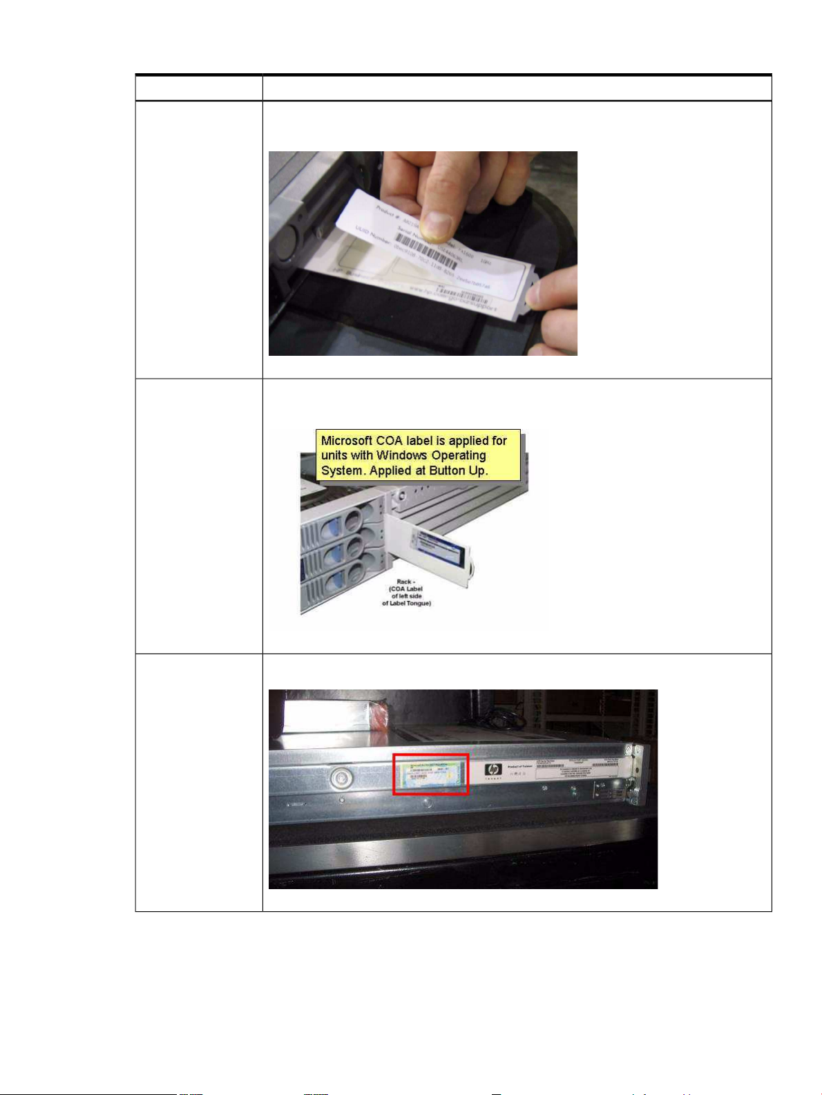
Table 1-2 Locating the Microsoft COA
LocationIntegrity Server
rx1620
rx2620
The COA is on the underside of the pullout strip located near the power switch, as shown
here (server is upside down in the image):
The COA is on a pullout strip located on the front of the system, adjacent to the hard drives,
as shown here:
The COA is located on the left side panel, in the middle, as shown here:rx2660
Locating the Microsoft Certificate of Authenticity 19
Page 20
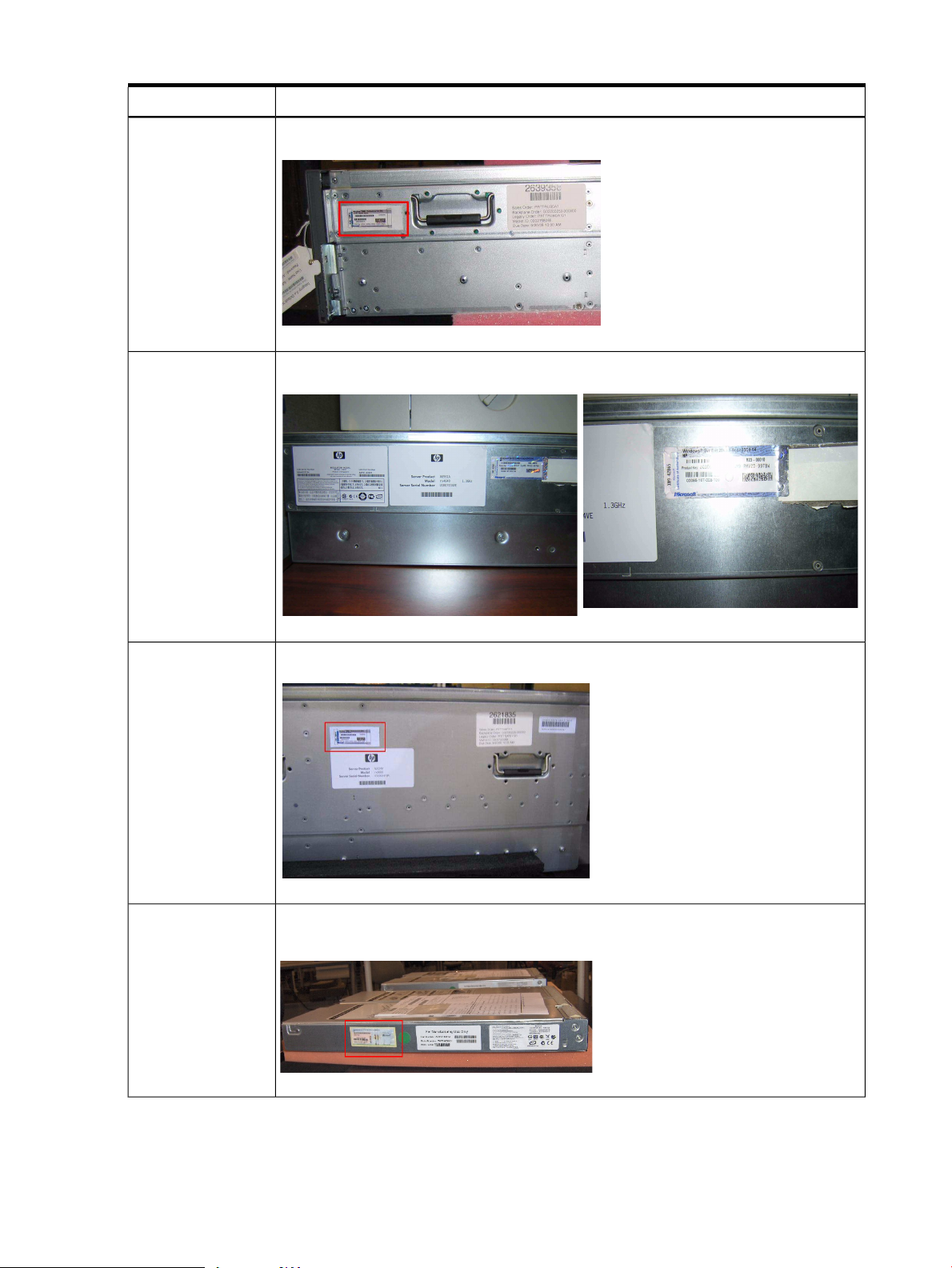
Table 1-2 Locating the Microsoft COA (continued)
LocationIntegrity Server
The COA is located on the left side panel, as shown here:rx3600
The COA is located on the left side panel, as shown here:rx4640
BL860c and BL870c
The COA is located on the left side panel. It as shown here:rx6600
The COA is located on the left side panel. If there is more than one label on the side panel,
the COA is the one farthest left, as shown here:
20 Preparing for the installation
Page 21
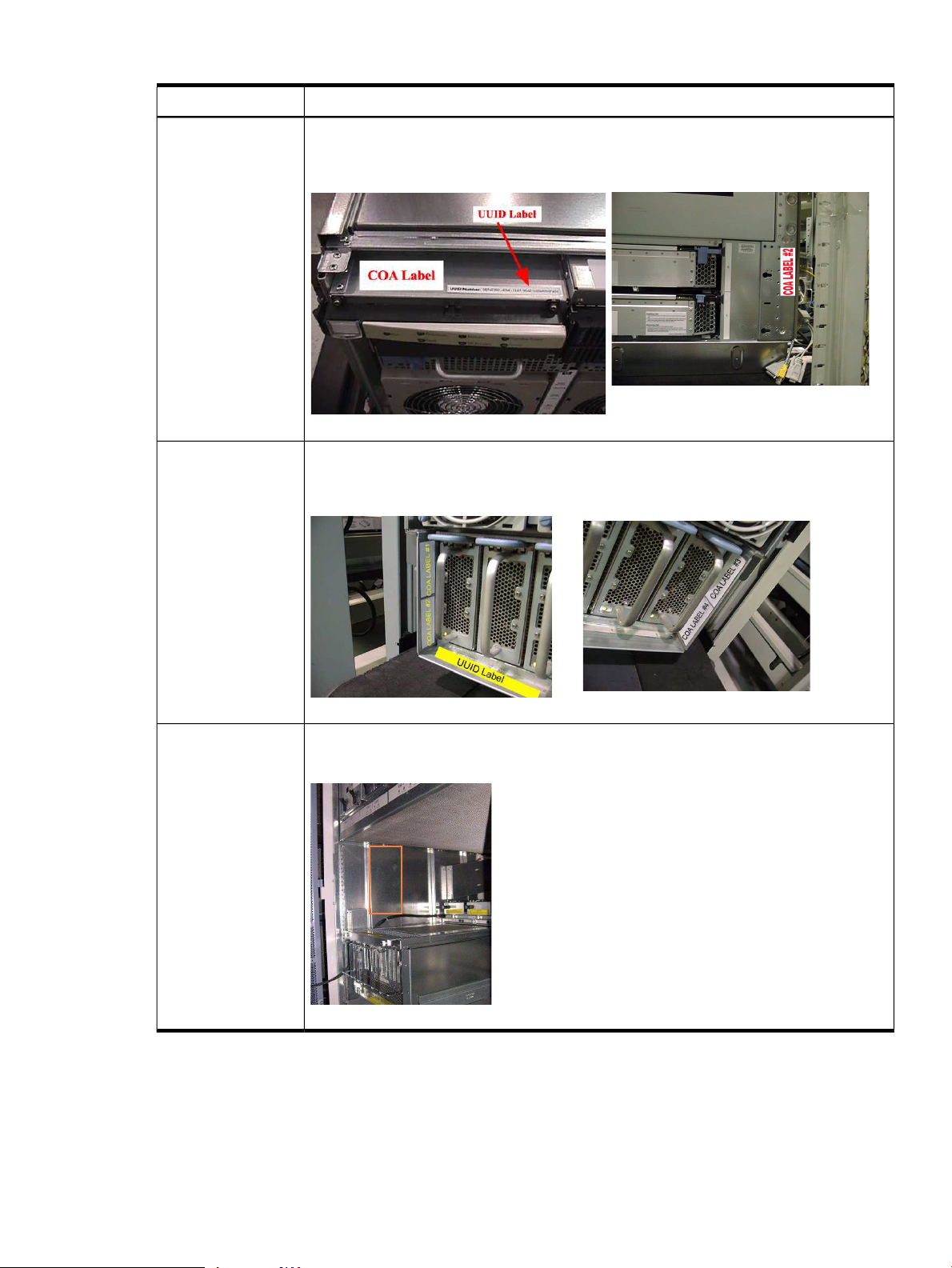
Table 1-2 Locating the Microsoft COA (continued)
LocationIntegrity Server
rx7620 and rx7640
rx8620 and rx8640
The COA is located on the front of the system, above the light panel, next to the UUID label,
as shown in the first illustration that follows. Additional COAs are shown in the second
illustration.
The COA is located in the front of the system, at the bottom, near the power supply as shown
in the first illustration that follows. If additional COAs are required, they are located as shown
in the second illustration.
Superdome (sx1000
and sx2000)
The COA is located inside the unit, on the left, in the open space between the cells and the
extended I/O cabinet (IOX), as shown here:
Locating the Microsoft Certificate of Authenticity 21
Page 22
Setting up a console
If you are installing locally, you must set up your server with either a headless console or a GUI
console.
Set up a headless console
A headless console is a PC running terminal emulation software such as PuTTY (available on
the Smart Setup media or from the web) or HyperTerminal, that connects to the server through
its management processor (MP) serial port or LAN port. The headless console provides a method
for connecting to servers that do not have legacy VGA graphics or PS/2 keyboard and mouse
hardware installed on them. It is good practice to configure servers this way (without legacy
VGA or keyboard/mouse hardware) because they are easier to setup, maintain, and operate.
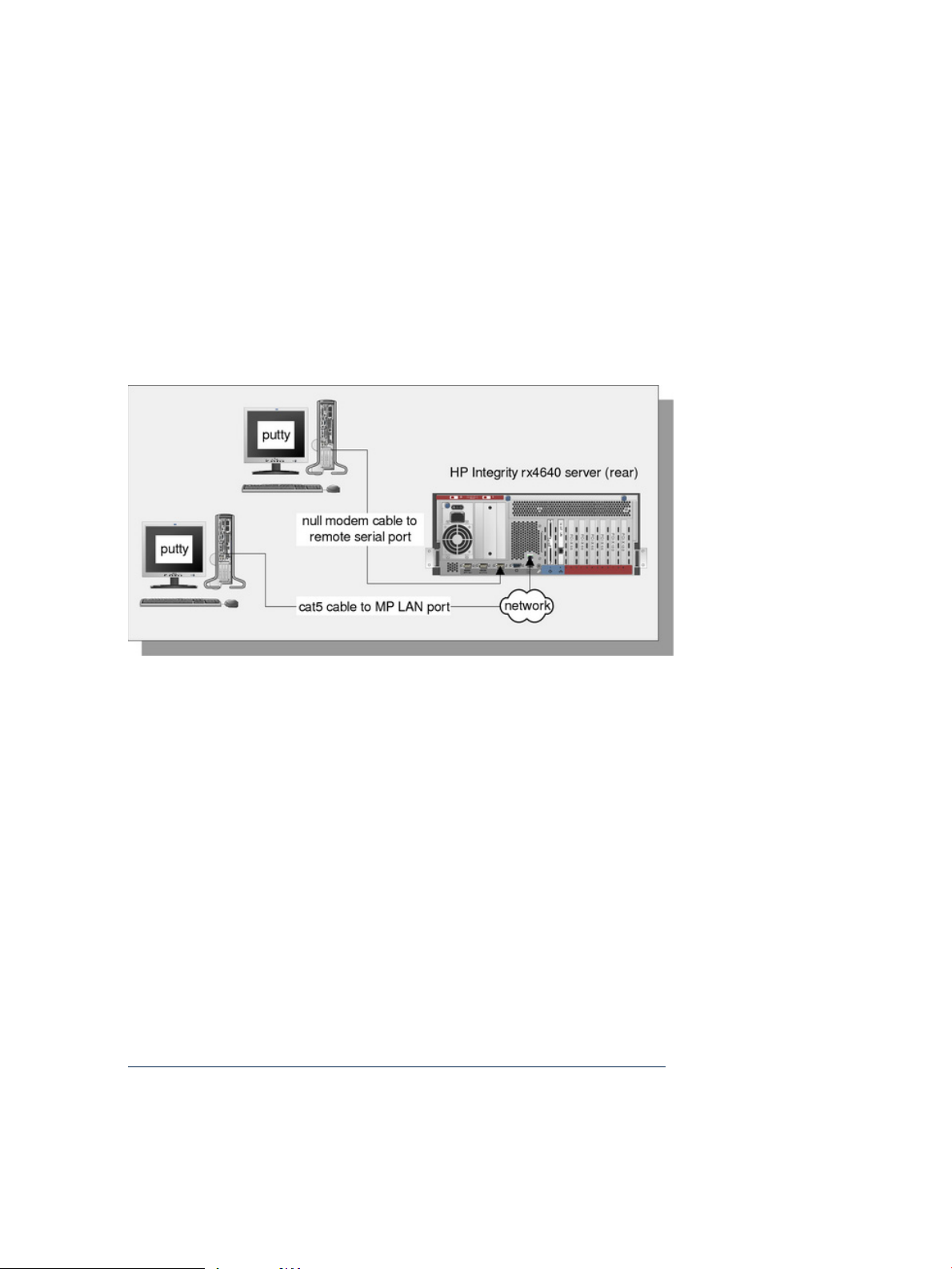
Figure 1-1 shows headless consoles connected to an HP Integrity rx4640 server.
Figure 1-1 Headless console configurations
When you use a headless console to install Windows, you can view detailed installation
information for each component by monitoring the setup log channels. See “Special Administration
Console” (page 94) for more information.
From the headless console, you can access the EFI Shell, the management processor (MP), and
the Microsoft Special Administration Console (SAC). You can use these utilities while installing
and administering Windows Server 2003 on HP Integrity servers. For more information about
the MP and SAC, see “Special Administration Console” (page 94).
You can configure a headless console in one of the following ways:
• Using a null modem cable
• Using a cat5 LAN cable
• Using a Remote Serial Console (applies to rx2660, rx3600, rx6600, BL860c, and BL870c servers
only)
The first two methods require a terminal emulation application such as HyperTerminal or PuTTY.
PuTTY is a free implementation of telnet and SSH for 32-bit Windows and UNIX. PuTTY provides
an X terminal. You must use PuTTY Version 0.59 or higher, available on the Smart Setup media
or from the PuTTY website at:
http://www.chiark.greenend.org.uk/~sgtatham/putty/download.html
Set up the headless console using a null modem cable
To set up the headless console using a null modem cable, complete the following steps:
1. Connect the PC to the server MP serial port with a null modem cable.
22 Preparing for the installation
Page 23

2. Install PuTTY on the client PC and specify these port settings:
• Bits per second: 9600
• Data bits: 8
• Parity: none
• Stop bits: 1
• Flow control: Xon/Xoff
3. Use the Keyboard Configuration Panel to map the backspace key to Control + H.
4. Boot the server.
5. Run PuTTY and press Enter. The MP login prompt appears.
6. Enter your user name and password, and the MP command prompt appears.
7. Enter the CO command to access the headless console.
Set up the headless console using a LAN
To set up the headless console over a LAN, complete the following steps:
1. Connect the PC to the server LAN port with a cat5 cable.
2. Use telnet to access the MP. The MP login prompt appears.
3. Enter your user name and password, and the MP command prompt appears.
4. Enter the CO command to access the headless console.
Set up the headless console using a Remote Serial Console (rx2660, rx3600, rx6600, BL860c, and BL870c only)
To set up the headless console (on rx2660, rx3600, rx6600, BL860c, and BL870c servers only) using
Remote Serial Console, complete the following steps:
1. Point a secure web browser at the name or IP address of the server MP.
2. Enter your user name and password to log in to the System Management Homepage.
3. On the Remote Console tab, and select Remote Serial Console in the left panel.
4. Click the Launch button and a new window appears, providing access to the headless
console.
Set up a GUI console
A GUI console is a VGA monitor, a USB HP keyboard, and a USB mouse connected to the server.
(You can use a USB-to-PS2 converter to connect to a console switch).
NOTE: If a VGA card is not already installed, you must install the HP Graphics and USB Combo
Card to use a GUI console. No other graphics card is supported by HP Integrity servers. Also,
only HP keyboards are supported with this card.
Figure 1-2 shows a GUI console connected to an HP Integrity rx4640 server.
Setting up a console 23
Page 24
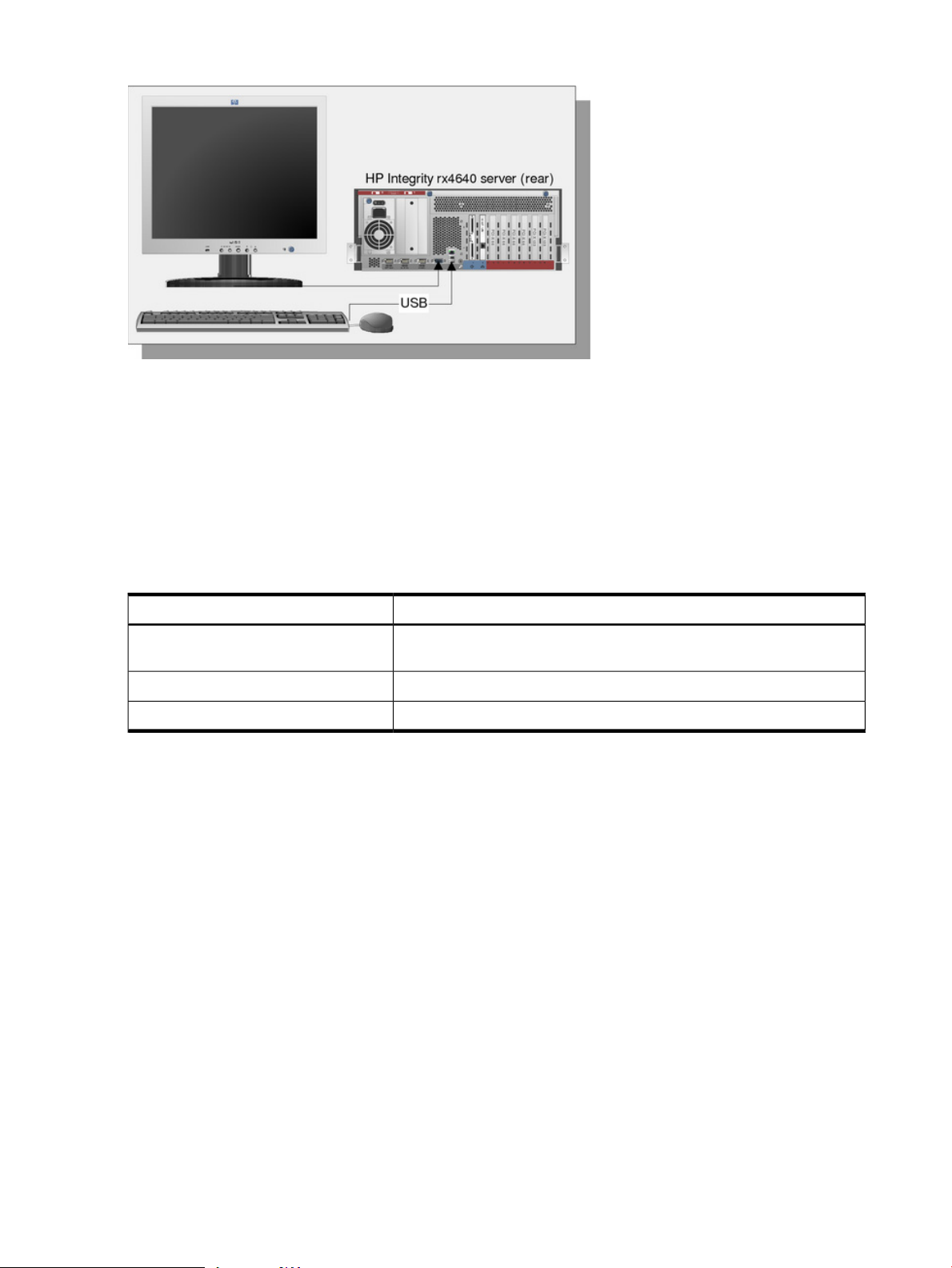
Figure 1-2 GUI console configuration
A GUI console provides complete access to all the installation and administration tasks that you
can perform on the server. You can use the GUI console to prepare the server for installation,
install the OS, and check server status after installation.
On servers configured with an internal graphics card, you can connect a monitor, keyboard, and
mouse directly to the appropriate ports. On servers without an internal graphics card, you must
first install an HP Graphics and USB Combo Card and connect the console to the appropriate
ports. Then, from an existing headless console, modify system configuration to redirect the output
to the GUI console.
Table 1-3 Graphics support on server models
Graphics CardServer Model
Built-in video graphicsrx1620, rx2660, rx3600, rx4640, rx6600,
BL860c, BL870c
Optional HP Graphics and USB Combo Card (HP part number A6968A)rx7620, rx8620, Superdome/sx1000
Optional HP Graphics and US Combo Card (HP part number A6968B)rx7640, rx8640, Superdome/sx2000
To install the HP Graphics and USB Combo Card using the Legacy interface (black background),
complete the following steps:
1. Install the HP Graphics and USB Combo Card in an open PCI slot in the server.
2. Connect a VGA monitor, USB HP keyboard, and USB mouse to the appropriate ports.
3. Boot the server to EFI.
4. At the headless console, from the EFI Boot Manager, select Boot Option Maintenance Menu.
5. Select Select Active Console Output Devices.
6. Highlight the line with the graphics card PCI device.
If the line does not begin with an asterisk, the device is disabled. Use the space bar to toggle
the state of the card from disabled to enabled (as indicated by the asterisk).
7. Select Save Settings to NVRAM and then Exit. The video display is now directed to the
GUI console.
To install the HP Graphics and USB Combo Card using the Enhanced interface (grey background),
complete the following steps:
1. Install the HP Graphics and USB Combo Card in an open PCI slot of the server.
2. Connect a VGA monitor, USB HP keyboard, and USB mouse to the appropriate ports.
3. Boot the server to EFI.
4. From the EFI Boot Manager, select Boot Configuration.
5. Select Console Configuration.
24 Preparing for the installation
Page 25

6. Select Select Output Console.
7. Select the graphics card PCI device and press Enter. The video display is now directed to
the GUI console.
Set up an Integrated Remote Console (rx2660, rx3600, rx6600, BL860c, and BL870c only)
The Integrated Remote Console (IRC) lets you use Windows clients running Internet Explorer
to remotely view and manage HP Integrity servers featuring the iLO 2 management processor.
This functionality is supported on rx2660, rx3600, rx6600, BL860c, and BL870c servers only.
The IRC combines keyboard, video, and mouse into a remote, virtual interface. Use it to view
the server’s display and directly interact with it. When you use IRC in combination with Virtual
Media (See “Set up a Virtual Media (vMedia) drive” (page 25)), you can perform remote GUI
installations of server operating systems and software. You can also use the IRC to perform server
maintenance tasks and run applications remotely that require keyboard and mouse input.
NOTE: You can use the Integrated Remote Console in place of the GUI Console method of
installation anywhere the GUI method is described in this document.
The IRC and vMedia features are enabled only after you have obtained and installed an iLO 2
MP Advanced Pack license (part number AB500A). If you are not licensed and try to use these
features, you see the message: iLO 2 feature not licensed. Free limited-term trial licenses
are also available.
For more information about the iLO 2 MP Advanced Pack licensing, or to obtain a free limited-term
license, go to:
http://h71028.www7.hp.com/enterprise/cache/279991-0-0-0-121.html.
Follow the factory installation or manual installation instructions located on the Integrated
Lights-Out Advanced Pack for HP Integrity Servers; Certificate of License to Use; License Installation
Card to activate your license.
This document is not intended to be a complete description of IRC or vMedia. For more
information about these powerful features, see the HP Integrity rx3600 and HP Integrity rx6600:
Integrated Lights-Out 2 Management Processor Operations Guide at:
http://docs.hp.com/en/AD217-9001A/index.html or
http://docs.hp.com/en/AD217-9001A/AD217-9001A.pdf
To set up an Integrated Remote Console (on rx2660, rx3600, rx6600, BL860c, and BL870c servers
only), complete the following steps:
1. Point a secure web browser at the name or IP address of the server MP.
2. Enter your user name and password to log in to the System Management Homepage.
3. On the Administration tab, select Licensing in the left panel.
4. Enter the license number.
5. On the Remote Console tab, select Integrated Remote Console in the left panel.
6. Click the Launch button. If Launch is greyed out, the license might be invalid or expired.
A new window appears, providing access to the IRC.
Set up a Virtual Media (vMedia) drive
Virtual Media (vMedia) provides you with virtual devices that mimic physical hardware devices
just as if they were physically connected, such as a virtual CD/DVD drive that can connect through
a network to the managed server. The vMedia device can be a physical CD/DVD drive on the
management workstation, or it can be an image file stored on a local disk drive or network drive.
Floppy disk or USB memory devices are not supported.
Setting up a console 25
Page 26

Booting from the iLO 2 MP CD/DVD enables you to upgrade the host system ROM, upgrade
device drivers, deploy an OS from network drives, and perform disaster recovery of failed
operating systems, among other tasks.
The iLO 2 MP device uses a client/server model to perform the vMedia functions. The iLO 2 MP
device streams the vMedia data across a live network connection between the remote management
console and the host server. The vMedia Java™ applet provides data to the iLO 2 MP as required.
NOTE: You can use a vMedia drive in place of a local CD or DVD drive anywhere that a local
CD/DVD drive is described in this document.
To set up a vMedia drive (on rx2660, rx3600, rx6600, BL860c, and BL870c servers only), complete
the following steps:
1. Point a secure web browser at the name or IP address of the server MP.
2. Enter your user name and password to log in to the System Management Homepage.
3. On the Administration tab, select Licensing in the left panel.
4. Enter the license number.
5. On the Virtual Devices tab, select Virtual Media in the left panel.
6. Click the Launch button. If Launch is greyed out, the license might be invalid or expired.
A new window appears, providing access to Virtual Media. Do on of the following actions:
• Select Local Media Drive, specify the CD or DVD drive on your client machine, and
insert the CD or DVD into that drive.
• Select Local Image File, and specify the ISO image of the desired CD or DVD.
7. Click Connect. The server now detects a new USB drive attached to it. This is the vMedia
drive.
Setting up PXE/RIS
A Remote Install Server (RIS) is a specialized Windows server used to perform multiple software
installations across a network. The RIS server, working in conjunction with an agent (the PXE
client) residing on target systems, performs automated installations. This method of installation
offers the following advantages:
• Installations are automated; no user intervention is needed
• You can install multiple servers in one batch job
• Each server receives a standardized image
• You can perform an installation from anywhere on the intranet
Figure 1-3 shows a sample PXE/RIS setup.
26 Preparing for the installation
Page 27
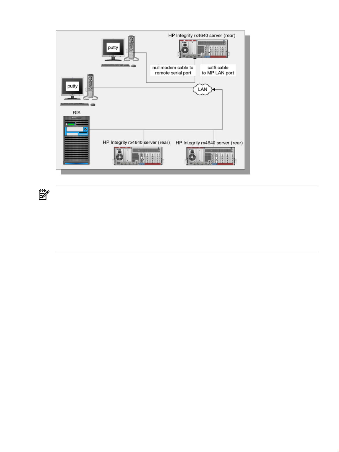
Figure 1-3 PXE/RIS configuration
NOTE: When you perform a PXE/RIS headless installation, note the following:
• Headless installations using PXE/RIS are not supported with Windows Server 2003,
Datacenter Edition. Use the HP Reinstallation media instead.
• Do not connect the RIS server to the Integrity server using your intranet during initial
Windows OS installation. Set up a small private network, populated with the RIS server, a
hub, and the system LAN NIC of the HP Integrity server. This protects the intranet from
errors that might occur during the Windows installation process. When the Windows OS
installation has completed, connect the RIS to the target Integrity servers using your intranet.
Remote Installation Services (RIS) enables you to create, maintain, and quickly install identical
OS and software configurations on multiple headless systems with a predefined level of user
interaction. RIS uses the preboot execution environment (PXE) to enable client computers without
an operating system to boot remotely to a RIS server. The RIS server then installs the operating
system over a TCP/IP network connection. You can create different sets of RIS images for different
groups of client computers. You can also use Group Policy settings to limit the installation options
that RIS presents to clients. In addition, you can configure RIS for either interactive or fully
automated installations.
Set up a RIS server
Setting up one or more RIS servers in your network requires careful planning, design, and
implementation. The following checklist provides an overview of the tasks involved in setting
up a RIS server:
• Ensure that both your RIS server and client (Integrity server) hardware meet the Remote
Installation Services (RIS) hardware requirements. The server hardware must meet the
minimum requirements for the version of Windows Server 2003 that you are installing.
• Ensure that your network is based on TCP/IP, and that a Domain Name System (DNS) server
exists on the network. You do not need to use the Microsoft version of DNS.
• Ensure that a Dynamic Host Configuration Protocol (DHCP) server exists on the network.
You do not need to use the Microsoft version of DHCP.
• Ensure that Active Directory exists on the network.
Setting up PXE/RIS 27
Page 28

Install RIS
• Install the RIS component on the RIS server.
• Run the RIS Setup Wizard.
See Also
For detailed descriptions of the concepts, tasks, best practices, and troubleshooting tips for setting
up a RIS server, see the Microsoft Windows Server 2003 Technical Reference website:
http://www.microsoft.com/windowsserver2003/proddoc/default.mspx.
You can install RIS either using the Control Panel or through an unattended Setup answer file.
To install using Add or Remove Programs, complete the following steps:
1. Go to Start > Settings > Control Panel, then double-click Add or Remove Programs and
select Add/Remove Windows Components to install the RIS component.
2. Open the RIS Setup Wizard and click Next. The RIS Setup wizard prompts you for
information about specific settings used in the RIS installation. The wizard prompts you to
do the following:
1. a. Enter the disk drive and directory to install RIS. The disk must be dedicated to the
RIS server with a recommended minimum 4 GB of space.
2. b. Select Respond to client computer requesting service. The RIS server begins
responding to client computers when the wizard is complete. Select Do not respond
to unknown client computers if you want the RIS server to respond only to prestaged
client computers in Active Directory.
3. c. Enter the location of the client images. This can be either the Windows Server 2003
Enterprise Edition with SP2 CD or a shared folder on the network that contains the
installation files.
4. d. Enter help text that describes the operating system installation choices to users or
clients of RIS.
Configure RIS
After the Remote Installation Services Setup Wizard completes, depending on the settings chosen,
the RIS server either services client computers or pauses while you configure advanced settings
using the RIS administration settings. The following list describes the available configuration
options.
• Specify which RIS servers are allowed to run on your network. This option prevents
• Use the Active Directory Users and Computers snap-in to set properties on individual RIS
• Use Group Policy to specify which installation options are presented to different groups of
• Use security descriptors or discretionary access control lists (ACLs) to specify which users
unauthorized (often referred to as rogue) RIS servers, ensuring that only those RIS servers
authorized by administrators can service clients. If an attempt is made to start an
unauthorized RIS server on the network, it will be shut down automatically and thus unable
to service client computers. A RIS server must be authorized before it can service client
computers.
servers that control how the server supplies RIS to requesting clients. To access the snap-in
go to Start > Programs > Administrative Tools, and then clicking Active Directory Users
and Computers.
users by the Client Installation wizard (CIW). For example, you can choose to allow a group
of users access only to the automatic setup option, and restrict access to all other options to
administrators.
or group of users can have access to the operating system images available on the RIS server.
You can use this method to guide users through the selection of the unattended OS installation
28 Preparing for the installation
Page 29

appropriate for their account privileges. By default, when an operating system image is
added to a RIS server, the image is available to all users serviced by that RIS server.
To configure settings for new clients for RIS, complete the following steps:
1. Open Active Directory Users and Computers.
2. In the console tree, go to Active Directory Users and Computers > Applicable domain
> Applicable organizational unit (such as Computers/Applicable RIS server) and right-click
the applicable RIS server.
3. Click Properties. In the Properties dialog box, go to the Remote Install tab and click
Advanced Settings.
4. In the Advanced Settings dialog box, go to the New Clients tab.
5. Select the client computer naming format you want to use, or click Customize to create a
client computer naming format.
6. To specify where to create the client computer account, click one of the following options:
• Default directory service location
• Same location as the user setting up the client computer
• The following directory service location
7. If you choose the last option, click Browse and specify where to create the computer accounts.
Authorize a RIS server in Active Directory
A RIS server must be authorized in Active Directory to be able to respond to clients requesting
service. If RIS is installed on a server that is not an authorized DHCP server, or added to a DHCP
server that is not authorized in Active Directory, you must complete the following steps:
1. Log in to the domain in which the RIS server resides. (The account you use must be a member
of the Enterprise Admins group.)
2. From the Start menu, point to Programs and Administrative Tools and click DHCP from
the list. This starts the DHCP Management snap-in.
3. Right-click the DHCP root node in the scope pane, and then click Manage Authorized
Servers.
4. Click Authorize, enter the IP address or name of the RIS server, and then click OK. When
prompted to ensure that this is the correct RIS server to authorize, click Yes.
The server will not respond to client requests until the changes to Active Directory have taken
effect. For these rights to apply immediately, on the domain controller on which your rights have
been set, complete the following steps:
1. On the Start menu, click Run.
2. Enter the cmd command.
3. At the command prompt, enter:
secedit /refreshpolicy /MACHINE_POLICY
Use the Client Installation Wizard
The following installation options are included in the Client Installation Wizard (CIW). Automatic
setup is available by default. RIS uses Group Policy settings to allow access to the automatic
setup option only, and to restrict all users and administrators from the rest of the installation
options described in the following list:
• Automatic Setup—This option allows you to select which operating system to install, but it
does not prompt you for specific configuration settings. If only one operating system option
is offered, you are not prompted, and an unattended installation of the operating system
image starts automatically.
• Custom Setup—This option allows you to override the automatic computer naming process
and the default location within the Active Directory where client computer accounts will
Setting up PXE/RIS 29
Page 30

be created. Help desk or administrators can use this option to preinstall a client computer
for someone else within the enterprise.
• Restart a Previous Setup Attempt—This option automatically restarts the operating system
installation process when an installation attempt fails before completion. This option does
not copy files from where the previous installation attempt failed; however, you are not
required to answer any questions answered within the CIW from the previous setup attempt.
• Maintenance and Troubleshooting—This option provides access to third-party maintenance
and troubleshooting tools that you can use before installing the operating system. Examples
of these tools include system flash BIOS updates, computer diagnostic tools, and virus
scanning utilities.
Preparing the server hardware
To set up the server hardware for OS installation, set up the boot drive, set up the CD/DVD drive,
and—if the server is cell-based—verify that the ACPI boot flag is set to ‘windows’ (see “Set ACPI
flag to windows (cell-based servers only)” (page 32)).
Set up the boot drive
The operating system installs through the boot controller detected as adapter zero to the drive
detected as drive zero.
CAUTION: HP strongly recommends that only the target OS drive be connected during
installation. This ensures that the OS is installed on the correct drive. Make sure that the Z: drive
letter is free. Windows Server 2003 with SP1 or SP2 creates the EFI partition here.
To set up the boot drive, complete the following steps:
1. Power off the server.
2. Make a note listing all device connections so you can reconnect them after the installation
3. Disconnect all mass storage devices from all controllers except the boot controller.
4. Configure the boot controller and boot drive. HP recommends that you install the boot
Boot to EFI
To launch the EFI Shell, complete the following steps:
1. Boot the server. The server automatically goes to the EFI Boot Manager Menu.
2. Arrow down to select EFI Shell.
3. Press Enter.
completes.
controller in the root cell.
NOTE: If you are using an HP Smart Array controller, see the controller’s user guide for
more information. You can interrupt the boot process to invoke the EFI-Based Option ROM
Configuration for Arrays (ORCA). To invoke this utility:
1. 1. Press F8 on the GUI console.
2. 2. Press ESC 8 on the headless console.
• If you are using the Enhanced EFI Boot Manager Menu (grey background), select EFI
Boot Manager Menu > EFI Shell
• If you are using the Legacy EFI Boot Manager Menu (black background), select EFI
Boot Manager Menu > EFI Shell [Built-in].
30 Preparing for the installation
Page 31

Locate the DVD/CD drive
When hardware (for example, HDD, a USB device, or a DVD-ROM drive) is added to a system
after it has booted to EFI, the EFI Shell environment does not automatically detect the new device.
You must reconnect the device driver for the EFI Shell to recognize the device.
The EFI Shell environment creates default mappings for all the device handles that support a
recognized file system. After you change the system configuration or add a new device, you
must regenerate these mappings.
To enable the EFI Shell to detect and access the DVD/CD drive, complete the following steps:
1. From the EFI Shell, enter the reconnect –r command.
The reconnect command reconnects one or more drivers from a device, disconnecting all
the drivers from all the devices and then reconnecting them. If you do not specify a device
handle, the reconnect operation is performed on all the handles in the system. If you do
specify a device handle, only the device handle and the devices below it are reconnected.
2. From the EFI Shell, enter the map -r command.
The -r option regenerates all the mappings in a system. The EFI Shell displays the device
mapping table, as follows.
fs0 : Acpi(PNP0A03,0)/Pci(2|0)/Ata(Primary,Master)/CDROM(Entry1)
blk0 : Acpi(PNP0A03,1)/Pci(1|0)/Scsi(Pun0,Lun0)
blk1 : Acpi(PNP0A03,0)/Pci(2|0)/Ata(Primary,Master)
blk2 : Acpi(PNP0A03,0)/Pci(2|0)/Ata(Primary,Master)/CDROM(Entry1
3. Note the device name of the CD device:
fs0
You use this to explore the contents of the CD or DVD.
The map command displays or defines a mapping between a user-defined name and a device
handle. The most common use of this command is to assign drive letters to device handles
that support a file system protocol. When these mappings are created, the drive letters can
be used with all the file manipulation commands.
Use the map command to create new mappings or delete an existing mapping with the -d
option. If you use the map command without any parameters, all the current mappings are
listed. If you use the -v option, the mappings are shown with additional information on
each mapped handle. The following table describes the device mapping fields.
Table 1-4 EFI device mapping fields
DescriptionItem
blkn
Acpi(Device,X)
This indicates a physical drive or a partition on a physical drive. A physical drive can be a
hard disk drive or a removable media drive. A
Partn
(in parentheses) appears when a disk drive contains a partition.
Acpi is Advance Configuration and Power Interface. The device type is the first entry in
parentheses. The second entry, X, is the PCI host number.
Pci(D/F)
Scsi(Pun.Lun)
HD(Part,Sig)
This indicates PCI-related information. D is the PCI device/slot number and F is the PCI
function number.
This denotes the physical characteristic of the SCSI disk. Pun is the SCSI number and Lun
is the LUN number on the physical device.
This indicates the partition Part and EFI signature Sig on the partition.
Preparing the server hardware 31
Page 32

Set ACPI flag to windows (cell-based servers only)
On cell-based servers, you must set the Advanced Configuration and Power Interface (ACPI)
flag to the value appropriate for the operating system it boots. For the server to boot to Windows
Server 2003, set the ACPI flag to windows.
If you purchased your server with a Windows operating system option, this flag is set to windows
in the factory. If you purchased the server with a different OS or no OS, you must set this flag
to windows.
CAUTION: If you boot the server to Windows Server 2003 without setting the ACPI flag to
windows, the OS displays a blue screen error.
To set the ACPI flag, complete the following steps:
1. From the EFI Shell, enter the acpiconfig command.
EFI displays the current ACPI settings. If the flag is set to windows, EFI displays:
acpiconfig: windows
2. If the flag is not set to windows, enter the acpiconfig windows command.
3. Enter the acpiconfig command again to display the settings again and verify that the flag
is set correctly.
Windows Server 2003 implements the ACPI 1.0b specification with some extensions from version
2.0, whereas HP-UX and Linux implement ACPI 2.0. As a result, the firmware has to be prompted
by this flag to recognize that the operating system to be booted is Windows Server 2003.
NOTE: Updating the system firmware can reset this flag to default. Verify that the flag is set
to windows after you flash the system firmware.
Set cell local memory to 100% (cell-based servers only)
HP recommends that you set the cell local memory (CLM) parameter to 100% for optimal server
performance. This setting allocates all available cell local memory for the use of that cell only,
preventing unnecessary reads and writes to physical memory over the server backplane.
Modify CLM settings for each nPartition using the nPartition command (parmodify). You must
first install nPartition tools on the Integrity server or on a remote management station. For detailed
information on the installation of these tools, see the nPartition Guide on your Smart Setup media
or at:
http://docs.hp.com/en/windows.html
To set the CLM parameter, complete the following steps:
1. From the server console, run the parmodify command with -p# and -m# options to modify
each cell’s attributes in each nPar you modify.
For example:
parmodify -p0 m0::::100%
where -p is the partition number and -m is the cell number in that partition sets cell local
memory to 100% in cell 0, partition 0.
2. Restart the server for the changes to take effect.
Specify NIC for a network boot
PXE is built on common Internet protocols and services, including TCP/IP, DHCP, and TFTP.
PXE extensions to the DHCP protocol enable RIS servers to communicate with the
network-bootable HP Integrity servers.
32 Preparing for the installation
Page 33

You can specify the network interface card (NIC) for PXE to use to communicate with the RIS
server. When the HP Integrity server boots from this NIC, it effectively boots from the remote
RIS server. Working in conjunction with the RIS server, PXE installs a new image of the Windows
Server 2003 on the HP Integrity server.
To enable PXE on the HP Integrity server from the EFI Shell, complete the following steps:
1. From the EFI Boot Manager, select EFI Shell. The device mapping table appears.
2. Enter the lanboot select command.
3. At the Select desired LAN: prompt, enter the number of the NIC card connected to
the PXE server.
4. Exit the EFI Shell.
Preparing the server hardware 33
Page 34

34
Page 35

2 Installing the OS
This chapter provides instructions for installing the operating system (OS) using a headless
console, a GUI console, or a PXE-enabled NIC. This chapter also provides reinstallation instructions
for Windows Server 2003. Each method comprises a series of tasks, concluding with two tasks
that verify that the OS was installed correctly. You must install the HP Support Pack after installing
the OS. You must also install any operating system and security updates using the Smart Update
media.
NOTE: HP Integrity servers must run Windows Server 2003 with either Service Pack 1 (SP1)
or Service Pack 2 (SP2). If you are running an earlier version of Windows Server 2003, you must
upgrade your operating system to SP1 or SP2. When updating to SP1 or SP2, perform the update
in the following order:
1. Install the latest HP Integrity Support Pack.
2. Reboot the machine.
3. Install the desired Service Pack.
4. Reboot the machine again.
5. Use the Windows Update Service to ensure that you have the latest Microsoft updates.
If the Windows Server 2003 operating system has already been installed on your system, or if it
was pre-installed by HP before your system was delivered, you do not have to perform any of
the steps described in this chapter. You can proceed directly to Chapter 3 (Chapter 3 “Installing
the Management Tools”) and begin the installation of your management tools software.
If your Windows Server 2003 operating system is not already installed, or if you wish to reinstall
it for some reason, or if you wish to migrate to Windows Server 2003 from another operating
system, you will need to install the OS and OS updates using one or more of the following steps
described in this chapter, in the following order:
• If you are installing your OS for the first time, or migrating from a different operating system:
— Pick one of the following local installation options:
◦ “Installing from a headless console”
◦ “Installing from a GUI console”
— Or, if you are not installing locally, pick one of the following remote installation options:
◦ “Installing from PXE”
◦ “Using Integrated Remote Console to install Windows on rx2660, rx3600, rx6600,
BL860c, and BL870c servers”
• If you are reinstalling your operating system, pick on of the following options:
— “Reinstalling from a headless console”
— “Reinstalling from a GUI console”
• After installing or reinstalling your operating system, perform the following tasks:
— “Applying OS updates”
— “Enabling Windows components”
— “Updating firmware, drivers, and software”
— See if you need to perform any final tasks here: “Miscellaneous installation issues”
Installing from a headless console
Installing from a headless console involves booting from the HP Smart Setup media, running
EBSU, launching Windows Setup, loading OS files to the boot disk, and then booting the server
from the boot disk. You should be connected to the management processor (MP) of the target
server using a terminal emulation application such as HyperTerminal.
Installing from a headless console 35
Page 36

Run EBSU
The EFI-Based Setup Utility (EBSU) provides an easy-to-use interface to flash the firmware,
partition the hard disk, install diagnostic tools, configure storage controllers, and run other EFI
utilities.
NOTE: If you are installing an HP Virtual Machines (HPVM) Windows guest, you do not need
to run EBSU as part of your setup. Skip this section and go directly to the next section (Run
Windows Setup).
To run EBSU, complete the following steps:
1. Power on the server. The server boots to EFI.
2. Load the HP Smart Setup media into the server DVD drive.
3. From the EFI Boot Menu, select Internal Bootable DVD and press Enter.
4. EBSU starts and displays the Welcome screen. Click OK and press Enter to continue.
You can use the EFI Boot Manager from the Enhanced interface (grey background) or the
Legacy interface (black background).
Figure 2-1 Enter EBSU
5. From the Main Menu, select Express Setup and press Enter.
6. EBSU displays the Express Setup introduction. Press Enter to continue.
Figure 2-2 Select Express Setup
36 Installing the OS
Page 37

7. EBSU displays the firmware update screen, listing each device, its installed firmware version,
and the firmware version on the Smart Setup media. Select the devices whose firmware you
want to update. To continue, select Next and press Enter.
Figure 2-3 Update firmware
NOTE: You might be able to use EBSU to flash the firmware of some devices. You cannot
flash the firmware if the installed version is the same or higher than the version on the Smart
Setup media. Also, you cannot use EBSU to flash the MP firmware. You must download the
latest MP firmware from the HP Integrity support site and flash it separately:
http://www.hp.com/support/itaniumservers/
8. To specify the disk partitions you want to create, select either ESP Only or ESP + HPSP +
MSR. HP recommends the default—ESP + HPSP + MSR—as a means to simplify the
maintenance of your server. Also, specify the option to install the Drive Explorer utility,
which enables you to browse a drive in EFI. Select Next and press Enter.
Figure 2-4 Partition disk
9. Specify the option to install offline diagnostic tools (from the HP Itanium Processor Family
offline diagnostics and utilities CD).
10. Also, specify the option to launch the Windows OS installer. Select Setup and press Enter.
Installing from a headless console 37
Page 38

Figure 2-5 Install diagnostic tools
11. EBSU displays the partition confirmation window. Select Continue and press Enter.
12. EBSU prompts you to insert the Microsoft Windows Server 2003 with SP2 CD in the DVD
drive. Insert the CD and press Enter.
Figure 2-6 Insert the Microsoft Windows Server 2003 CD
Run Windows Setup
Windows Setup prompts you to create a system partition on the boot disk if needed, copies the
OS files on to that partition, and attempts to reboot from the boot disk. To run Windows Setup,
complete the following steps:
1. Insert the Microsoft Windows Server 2003 with SP2 CD in the DVD drive, and Windows
Setup launches. Press Enter to start the installation.
NOTE: If you are installing an HP Virtual Machines (HPVM) Windows guest, you also
need to issue an IN command (for “insert”) from the HPVM console menu every time you
insert a disc. If you forget to do this, the server does not recognize the disc and appears to
hang.
2. Windows Setup prompts you to select Express Install. Select Express Install by pressing
Enter.
38 Installing the OS
Page 39

3. If Windows Setup cannot find a system partition, it prompts you to create one. Press Enter
to continue. Windows creates a partition and then prompts you to format it.
4. Select the partition in which you want to install the OS and press Enter. Windows formats
the partition if necessary, checks the partition for errors, and begins to copy the OS files.
5. Monitor the copy process until it completes. You can monitor installation progress from the
SAC command prompt by using these three channels: setuplog.txt, setupact.log,
and setuperrlog. See “Special Administration Console” (page 94) for more information.
Upon completion, Windows Setup counts down to a reboot. Allow the system to reboot.
Enter the product key
To enter the product key, complete the following steps:
1. At the SAC prompt, press Esc+Tab to switch to a new command channel.
2. When prompted, enter the product key (either a volume license key or the key found on the
COA label), and press Enter.
Installing from a GUI console
This sections describes how to install the OS using a GUI console.
Run EBSU
EBSU provides an easy-to-use interface to flash the firmware, partition the hard disk, install
diagnostic tools, configure storage controllers, and run other EFI utilities.
NOTE: If you are installing an HP Virtual Machines (HPVM) Windows guest, you do not need
to run EBSU as part of your setup. Skip this section and go directly to the next section (Run
Windows Setup).
To run EBSU, complete the following steps:
1. Power on the server. The server boots to EFI.
You can use the EFI Boot Manager from the Enhanced interface (grey background) or the
Legacy interface (black background).
2. Load the HP Smart Setup media into the server DVD drive.
3. From the EFI Boot Menu, select Internal Bootable DVD and press Enter.
4. EBSU starts and displays the Welcome screen. Click OK and press Enter to continue.
Figure 2-7 Enter EBSU
5. From the Main Menu, select Express Setup and press Enter.
Installing from a GUI console 39
Page 40
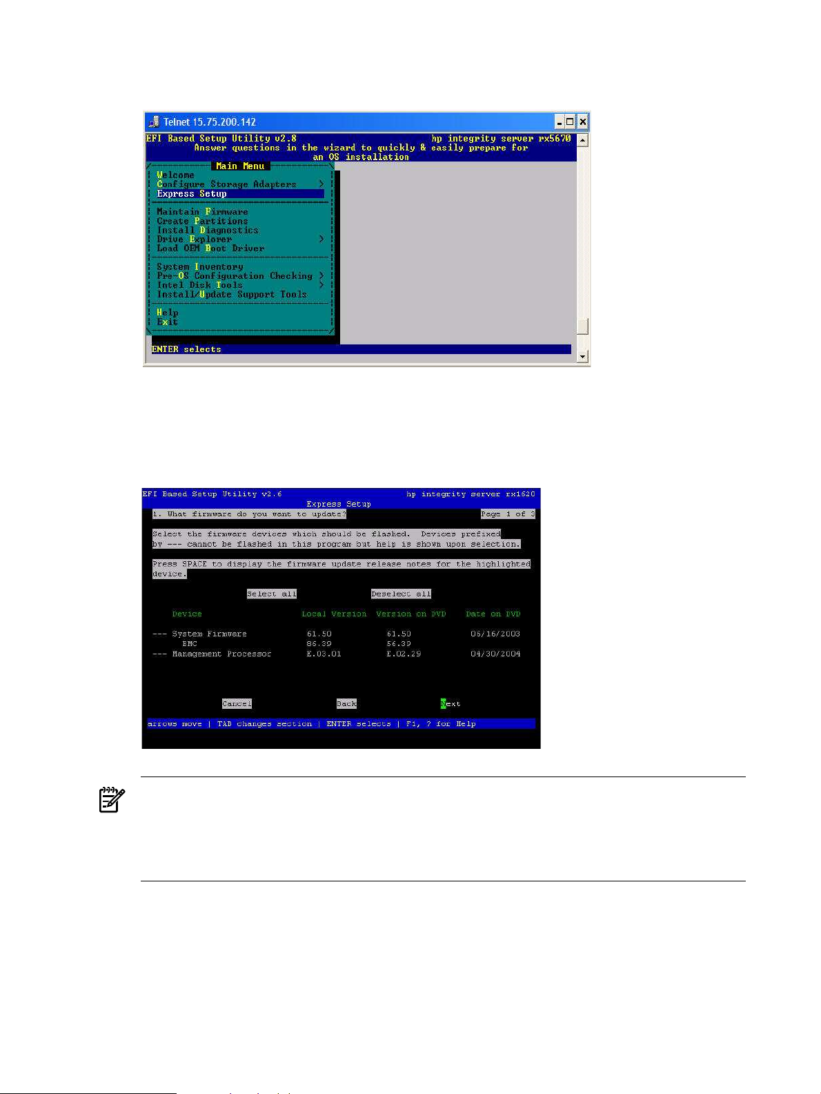
6. EBSU displays the Express Setup introduction. Press Enter to continue.
Figure 2-8 Select Express Setup
7. EBSU displays the firmware update screen, listing each device, its installed firmware version,
and the firmware version on the Smart Setup media. Select the devices whose firmware you
want to update. To continue, select Next and press Enter.
Figure 2-9 Update firmware
NOTE: You might not be able to use EBSU to flash the firmware of some devices. You
cannot flash the firmware if the installed version is the same or higher than the version on
the Smart Setup media. Also, you cannot use EBSU to flash the Management Processor (MP)
firmware. You must download the latest MP firmware from the HP Integrity support site:
http://www.hp.com/support/itaniumservers/ and flash it separately.
8. To specify the disk partitions you want to create, select either ESP Only or ESP + HPSP +
MSR. HP recommends the default—ESP + HPSP + MSR—as a means to simplify the
maintenance of your server. Also, specify the option to install the Drive Explorer utility,
which enables you to browse a drive in EFI. Select Next and press Enter.
40 Installing the OS
Page 41

Figure 2-10 Partition disk
9. Specify the option to install offline diagnostic tools (from the HP Itanium Processor Family
offline diagnostics and utilities CD).
10. Also, specify the option to launch the Windows OS installer. Select Setup and press Enter.
Figure 2-11 Install diagnostic tools
11. EBSU displays the partition confirmation window. Select Continue and press Enter.
Installing from a GUI console 41
Page 42
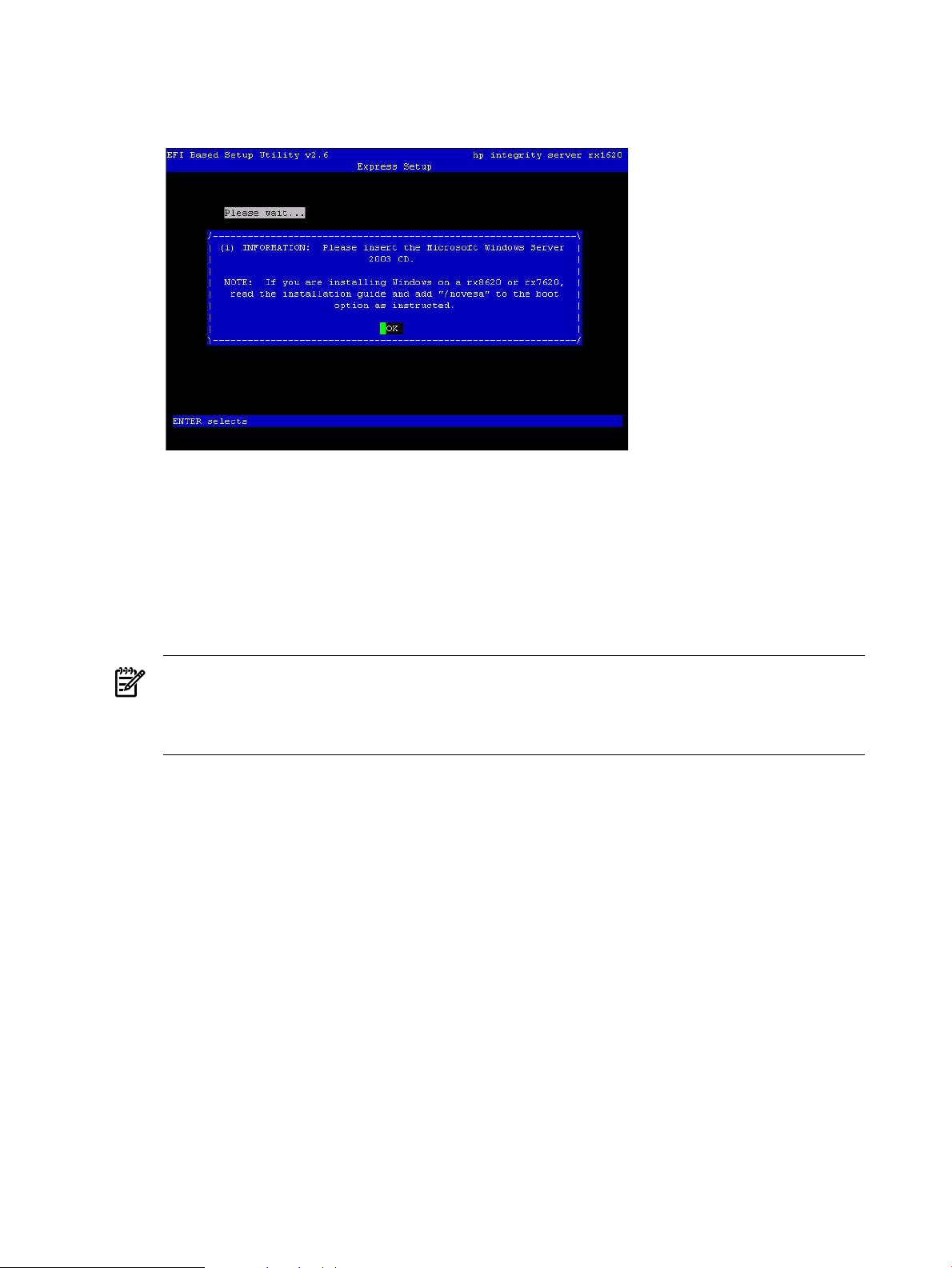
12. EBSU prompts you to insert the Microsoft Windows Server 2003 with SP2 CD in the DVD
drive. Insert the CD and press Enter.
Figure 2-12 Insert the Microsoft Windows Server 2003 CD
Run Windows Setup
Windows Setup prompts you to create a system partition on the boot disk if needed, copies the
OS files on to that partition, and attempts to reboot from the boot disk.
To run Windows Setup, complete the following steps:
1. Insert the Microsoft Windows Server 2003 with SP2 CD in the DVD drive, and Windows
Setup launches. Press Enter to start the installation.
NOTE: If you are installing an HP Virtual Machines (HPVM) Windows guest, you also
need to issue anINcommand (for “insert”) from the HPVM console menu every time you
insert a disc. If you forget to do this, the server does not recognize the disc and appears to
hang.
2. Windows Setup prompts you to select Express Install. Select Express Install by pressing
Enter.
3. If Windows Setup cannot find a system partition, it prompts you to create one. Press Enter
to continue. Windows creates a partition and then prompts you to format it.
4. Select the partition in which you want to install the OS and press Enter. Windows formats
the partition if necessary, checks the partition for errors, and begins to copy the OS files.
5. Monitor the copy process until it completes. You can monitor installation progress from the
SAC command prompt by using these three channels: setuplog.txt, setupact.log,
and setuperrlog. See “Special Administration Console” (page 94) for more information.
Upon completion, Windows Setup counts down to a reboot. Allow the system to reboot.
Specify server settings
When the system boots, Windows displays a screen indicating that an EMS channel (MP remote
port) is present. It can take 2 to 15 minutes for the mouse and keyboard to start operating in this
mode.
To set up Windows Server 2003 after initial boot from the local console, complete the following
steps:
1. When prompted to enter server settings, click OK.
42 Installing the OS
Page 43

2. In the Windows Setup Wizard, enter the following setup information:
a. In the License Agreement window, click Accept and then Next.
b. In the Regional and Language Options window, click Next.
c. In the Your Product Key window, enter the product key. The product key is located on
the label attached to the server.
d. In the Licensing Modes window, select the license you purchased.
e. In the Administrator Password window, enter the server name and a password.
f. In the Date and Time window, select the appropriate time zone, and click Next.
The server reboots to the EFI Boot Manager.
3. From the EFI Boot Menu, select Windows Server 2003. The server boots to Windows.
4. Log in to the system with the administrator password you specified earlier.
5. Install the HP Update CD and the HP Support Pack after installing the OS.
Installing from PXE
When a PXE-enabled client connected to the network boots up, the computer initiates a network
service request. A DHCP discover packet is sent to the network requesting the IP address of an
available RIS server. The DHCP server responds to the request by providing an IP address to
the client. Any available RIS server can respond with its IP address, and the name of the boot
file the client should request if the client selects that RIS server for service.
Support for PXE/RIS installations is limited to the HP Integrity servers listed in the following
table.
Table 2-1 Integrity servers supporting PXE/RIS installations
rx8620, rx8640
To install Windows Server 2003 from PXE, complete the following steps:
1. From EFI, select the Boot Manager.
2. At the Boot Manager, select the Boot Options menu.
3. From the list of available boot sources, select the NIC to boot from and press Enter.
4. At the PXE boot status window, press Enter to continue.
5. At the login screen, enter a valid user name and password, and press Enter.
6. At the OS selection screen, select the OS to be installed and press Enter to start the installation.
7. Complete the installation by following the instructions on the screen.
Reinstalling from a headless console
HP Integrity servers that are factory-installed with Windows Server 2003 are shipped with HP
Reinstallation media, which enables you to restore the system to its factory settings, if necessary.
PXE/RIS supportServer
Yesrx1620, rx2620, rx4640
Yes — Enterprise edition onlyrx2660, rx3600, rx6600, BL860c, BL870c, rx7620, rx7640,
Yes — Enterprise edition onlySuperdome (sx1000 and sx2000)
Installing from PXE 43
Page 44

Reinstalling the operating system involves loading the image from the Reinstallation media onto
the boot disk and, after Windows Server 2003 is loaded, specifying the server settings.
CAUTION: Reinstallation overwrites all files on the boot disk. The boot disk is determined by
bus search order and might not be the disk you expect it to be. HP recommends disconnecting
or unplugging all drives from the server except the boot disk. This includes all SAN storage, too.
Load the system image
To reinstall Windows Server 2003 from a headless console, complete the following steps:
1. From the headless console, log in to the MP using a terminal emulator such as HyperTerminal
or PuTTY.
2. Boot the server to EFI.
3. Because Windows Server 2003 cannot create a boot entry if one already exists, you must
delete the existing boot entry. To delete the boot entry:
a. Do one of the following:
• If you are using the Enhanced EFI Boot Manager Menu (grey background), select
EFI Boot Manager Menu > Boot Configuration > Remove Boot Entry.
• If you are using the Legacy EFI Boot Manager Menu (black background), select
EFI Boot Manager Menu > Boot Option Maintenance Menu > Delete Boot
Option(s).
b. Arrow down to select the Windows Server 2003 boot entry to delete and press Enter.
NOTE: The next step applies to factory-installed systems that require the use of the HP
Reinstallation media only. If the Windows boot entries are not all deleted, the boot file
bootxxx.efi is not created.
4. Insert the HP Reinstallation media in the DVD drive of the target system.
IMPORTANT: If you are installing an HP Virtual Machines (HPVM) Windows guest, you
also need to issue an IN command (for “insert”) from the HPVM console menu every time
you insert a disc. If you forget to do this, the server does not recognize the disc and appears
to hang.
NOTE: With rx2660, rx3600, rx6600, BL860c, and BL870c servers, you can also use Virtual
Media (vMedia) as the source of the reinstallation image.
5. Reboot the server.
6. At the MP> prompt, on the headless console, enter the CO command to launch the live console.
NOTE: With rx2660, rx3600, rx6600, BL860c, and BL870c servers, you can also use Remote
Serial Console to perform this step.
7. Select EFI Boot Manager menu > Internal Bootable DVD and press Enter. The server boots
from the HP Reinstallation media.
8. At the SAC> prompt, enter the cmd command.
9. Switch to a new command channel by pressing Esc+Tab.
10. At the x:\ia64\system32> prompt invoke the installation menu by entering txtrestore.
A Warning message appears stating that all data, including the partition table, will be lost
upon reinstallation.
11. Select Y to continue.
44 Installing the OS
Page 45

12. Select the desired partition size (33 GB is recommended). The maximum partition size is
limited to the size of the drive. Select Y to continue.
NOTE: The installation process copies files to the hard disk. Do not power off the server
during the installation.
13. When the installation process completes, press any key to reboot the server.
14. The local console displays a screen indicating that the EMS was detected. When prompted
to use the local console, do not click OK.
15. Return to the headless console and perform system setup as indicated in the following
section.
Specify server settings
To set up Windows Server 2003 after initial boot from a headless console, complete the following
steps:
1. At the SAC> prompt, switch to channel one by pressing Esc+Tab.
The system displays the following screen:
*****************************************************************
Name: Unattended Setup Channel
Description: Provide parameters to automate Setup
Type: VT-UTF8
Channel GUID: 0cfc0ee2-3a27-11d7-8484-806e6f6e6963
Application Type GUID: 00000000-0000-0000-0000-000000000000
Press <esc><tab> for next channel.
Press <esc><tab>0 to return to the SAC channel.
Use any other key to view this channel.
*****************************************************************
2. Press any key and then press Page Down.
3. Accept the license agreement by pressing F8. On the Windows default terminal emulator,
F8 is <Esc> 8. Press 8 within 2 seconds after pressing Esc. Otherwise, the system registers
only the Esc key and reboots.
4. Enter the product key. The product key is located on the Microsoft Certificate of Authenticity
attached to the server.
5. Enter the administrator password and reenter to confirm. The mini-setup process continues
automatically and after completion, it reboots the system. Wait for the SAC> prompt to
reappear.
6. Open a terminal server client and connect to the IP address of the server. Change the
computer name and IP address, if needed.
7. On the desktop, open the Online Reference page, scroll to the bottom, and click the link to
c:\hputils\usercompanyname.cmd.
8. When prompted, enter company and user name, and click OK.
9. Login as the system administrator.
10. At the prompt, Please mount HP Smart Setup media on the Server's DVD
drive to install utilities, do one of the following:
• If you want to update the drivers and install the online utilities, mount the HP Smart
Setup media shipped with your system and click Yes to continue.
• If you do not want to update the drivers and install the online utilities at this time, click
No to continue.
Reinstalling from a headless console 45
Page 46

NOTE: If you select No, you should inspect the system and proceed to update the
drivers and install the utilities before bringing the system online.
11. At the system reboot prompt, click Yes to reboot the system and implement your changes.
After the reboot, your system is ready to go online.
Reinstalling from a GUI console
HP Integrity servers that are factory-installed with Windows Server 2003 are shipped with the
HP Reinstallation media, which enables you to restore the system to its factory settings, if
necessary. Reinstalling the operating system involves loading the image from the Reinstallation
media on to the boot disk and, after Windows Server 2003 is loaded, specifying the server settings.
CAUTION: Reinstallation overwrites all files on the boot disk. The boot disk is determined by
bus search order and might not be the disk you expect it to be. HP recommends disconnecting
or unplugging all drives from the server except the boot disk. This includes all SAN storage, too.
Load the system image
To install the Windows Server 2003 with SP2 operating system on the server from the local
console, complete the following steps:
1. Boot the server to EFI.
2. Because Windows Server 2003 cannot create a boot entry if one already exists, you must
delete the existing boot entry. To delete the boot entry:
a. Do one of the following:
• If you are using the Enhanced EFI Boot Manager Menu (grey background), select
EFI Boot Manager Menu > Boot Configuration > Remove Boot Entry.
• If you are using the Legacy EFI Boot Manager Menu (black background), select
EFI Boot Manager Menu > Boot Option Maintenance Menu > Delete Boot
Option(s).
b. Arrow down to select the Windows Server 2003 boot entry to delete and press Enter.
NOTE: The next step applies to factory-installed systems that require the use of the HP
Reinstallation media only. If the Windows boot entries are not all deleted, the boot file
bootxxx.efi is not created.
3. Insert the HP Reinstallation media in the DVD drive.
IMPORTANT: If you are installing an HP Virtual Machines (HPVM) Windows guest, you
also need to issue anINcommand (for “insert”) from the HPVM console menu every time
you insert a disc. If you forget to do this, the server does not recognize the disc and appears
to hang.
4. From the EFI Boot Manager, select Internal Bootable DVD, if the entry is present.
If this entry is absent, do the following:
a. Select EFI Shell.
b. In the EFI Shell, select the DVD file system. For example, if the DVD file system is fs1,
enter fs1:
c. Start the boot loader by entering setupldr.
5. Click Re-Install on the HP Recovery Console.
6. Enter Y to continue with the reinstallation.
46 Installing the OS
Page 47

7. Select the desired partition size (33 GB is recommended). The maximum partition size is
limited to the size of the drive. Click OK to continue.
NOTE: The installation process copies files to the hard disk. The progress bar may increase
or decrease throughout this process. Do not power off the server during the installation.
8. When the installation process displays a dialog box, click OK to continue.
9. Click Exit. The server reboots to the Windows Server 2003 operating system. Set up the
system according the instructions in the following section.
Specify server settings
To set up Windows Server 2003 after initial boot from the local console, complete the following
steps:
1. Start the server. Windows displays a pop-up screen indicating that an EMS channel (headless
server MP port) is present. It can take 2 to 15 minutes for the mouse and keyboard to start
operating in this mode.
2. When prompted to enter setup information at the local console, click OK.
3. From the Windows Setup Wizard, enter the following setup information:
a. In the License Agreement window, click Accept and then Next.
b. In the Regional and Language Options window, click Next.
c. In the Your Product Key window, enter the product key. The product key is located on
the label attached to the server.
d. In the Licensing Modes window, select the license you purchased.
e. In the Administrator Password window, enter the server name and a password.
f. In the Date and Time window, select the appropriate timezone, and click Next.
The server reboots to the EFI Boot Manager and then boots up Windows Server 2003. You can
now log in to the server using the administrator password you selected.
After logging in as the system administrator, complete the following steps:
1. At the prompt, Please mount HP Smart Setup media on the Server's DVD
drive to install utilities, do one of the following:
• If you want to update the drivers and install the online utilities, mount the HP Smart
Setup media shipped with your system and click Yes to continue.
• If you do not want to update the drivers and install the online utilities at this time, click
No to continue.
NOTE: If you select No, you should inspect the system and proceed to update the
drivers and install the utilities before bringing the system online.
2. At the system reboot prompt, click Yes to reboot the system and implement your changes.
After the reboot, your system is ready to go online.
Applying OS updates
Install all the OS updates and security updates from the HP Smart Update DVD. You can find
the Smart Update DVD in the Integrity Essentials Foundation Pack kit along with the Smart
Setup CD.
To apply the OS updates using the HP Smart Update DVD, complete the following steps:
1. Insert the HP Smart Update DVD. The Smart Update screen appears. Click the QFEs for
SP1 or QFEs for SP2 tab (whichever applies).
2. Use the links on the left navigation bar to go directly to Operating System Updates, Security
Updates, Clustering Updates, or Documents.
Applying OS updates 47
Page 48

3. To install all operating system updates, click Install... in the Operating System Updates
section. The HP Package Setup screen appears.
4. Click Install. The HP Setup screen appears. Click Install to continue with the installation or
click Close to exit setup. When you click Install, a command window appears, listing each
update as it installs. Sometimes these are very large updates and can take several minutes
each to install.
5. When prompted, click Reboot to complete the installation. HP recommends rebooting after
each QFE bundle installs to ensure correct installation.
6. To install all Security updates, click Install... in the Security Updates section. The HP Package
Setup screen appears.
7. Click Install. The HP Setup screen appears. Click Install to continue with the installation,
or click Close to exit setup. When you click Install, a command window appears, listing
each update as it installs. Sometimes these are very large updates and can take several
minutes each to install.
8. When prompted, click Reboot to complete the installation. HP recommends rebooting after
each QFE bundle installs to ensure correct installation.
9. At any time, if you want to read a more detailed description about a particular update, click
on its Knowledge Base (KB) ID number and you are linked to the relevant article on the
Microsoft website.
10. Install the Clustering Updates in the same manner, but only if your server will function as
a node in a cluster.
11. After installing all desired updates, use the Microsoft Windows Update functionality in the
operating system (Start > Help and Support > Support Tasks > Windows Update) to
check for any updates that have been issued since your Smart Update media was released.
You can also run QFE Check, which is included with each Smart Component (when you
extract the Smart Component bundle).
NOTE: You can also extract Smart Components to your hard drive and install the QFEs
individually, but HP recommends installing them as a group, as described above.
Enabling Windows components
This section describes installation of the Windows components that enable networking.
Install TCP/IP
NOTE: Install TCP/IP before installing the HP management agents.
To install the TCP/IP driver, complete the following steps:
1. Select Start > Settings > Control Panel > Network Connections.
2. Right-click the Local Area Connection icon and select Properties.
3. Select Internet Protocol TCP/IP and click Install.
4. Click OK.
Install SNMP
SNMP support is included in Windows Server 2003. To install the SNMP Protocol, complete the
following steps:
1. Select Start > Settings > Control Panel.
2. Click Add or Remove Programs.
3. Click Add/Remove Windows Components.
48 Installing the OS
Page 49

4. In the Windows Component wizard, clear all components except Management and
Monitoring Tools, then click Next.
5. From the Management and Monitoring Tools window, select Simple Network Management
Protocol, then click OK. The Component Wizard page appears.
6. Click OK to start the installation.
7. Monitor the installation and click Finish to complete it.
Configure SNMP
To configure SNMP, complete the following steps:
1. From the Control Panel select Administrative Tools > Services, right-click SNMP Service,
and select Properties. The SNMP Service Properties (Local Computer) dialog appears.
2. On the Security tab, click Add to add the community string.
3. Select a name for the string and access rights.
4. Click Apply, then click OK.
Set IP addresses from a headless console
To set the MP IP from a headless console, complete the following steps:
1. Use an RS232 cable to connect the target server console port to the COM port of a working
system.
2. Launch a terminal emulation program, such as HyperTerminal.
3. In the Connect Using pull-down list, select the COM port connected to the RS232 cable. Click
OK.
4. When prompted, enter the default baud rate of 9600, and HyperTerminal connects to the
MP.
5. Log in to the MP using the default MP administration user name and password Admin /
Admin.
6. Enter the CM command to access the Command menu.
7. Enter the LC command to configure the network settings. Enter A to configure all the
parameters, or enter the letter designating the parameters you want to modify. Typically, I
= IP address, S = Subnet mask, and G = Gateway address.
To set the server IP address from a headless console, complete the following steps:
1. Use HyperTerminal or PuTTY to log in to the MP.
2. Enter the CO command go to the SAC prompt.
3. At the SAC> prompt, enter the I command to specify the network number, IP address, and
subnet mask. For example:
I<network#><IPaddress><subnet mask>.
Set up and run a Remote Desktop Connection
The remote administration mode is enabled by default on Windows Server 2003 if you use the
HP Reinstall media. If you install or reinstall using Microsoft OS media, the Remote Desktop
functionality is disabled. Users must have unique user names. Windows does not permit two
users with the same name to log on simultaneously.
To set up a remote desktop connection from a GUI console, complete the following steps:
1. Right-click the My Computer icon and click Properties.
2. On the Remote tab, select Enable Remote Desktop on this computer.
3. Click OK.
4. On the Control Panel, double-click Windows Firewall.
5. Go to the Exceptions tab, check Remote Desktop, and click OK.
Enabling Windows components 49
Page 50

To set up a remote desktop connection from a headless server, complete the following steps:
1. Go to the SAC console.
2. At the SAC> prompt, enter cmd.
3. Press Esc+Tab to enter the Command Prompt console (this requires logging in as
Administrator).
4. Enter the following command from the Windows command prompt:
reg add "HKLM\System\CurrentControlSet\Control\Terminal Server" /v
fDenyTSConnections /t REG_DWORD /d 0 /f
5. This step applies only to installations using Windows Server 2003 64-bit for Itanium Release to
Manufacturing (RTM) with SP2 slipstream media:
To enable Remote Desktop traffic through the default Windows Firewall settings, at the
C:\Windows\system32> prompt, enter the following command:
netsh firewall set service remotedesktop enable all
and press the Enter key.
To run Remote Desktop Connection, complete the following steps:
1. Click Start > Programs > Accessories > Communications > Remote Desktop
Connection.
2. Click the Computer drop-down list.
3. Select Browse for more.
4. Select the HP Integrity server with which you want to establish a connection.
5. Click OK.
6. Click Connect.
7. Log in to the remote server. Windows displays the remote server desktop.
Updating firmware, drivers, and software
To update your system after installing the OS, install the Integrity Support Pack from the HP
Smart Setup CD.
IMPORTANT: HP Customer Engineers must perform firmware updates for Superdome, rx8620,
and rx7620 servers in compliance with the support agreement.
You must install the Integrity Support Pack if you did not use the HP Reinstallation media to
install the OS.
Enable greater than 256 interrupts (cell-based servers only)
NOTE: This section (Enabling greater than 256 interrupts) applies only if you are using Windows
Server 2003 with SP1. If you are using Windows Server 2003 with SP2, you can skip this section.
When you use Enterprise Edition on cell-based servers (rx7620, rx7640, rx8620, rx8640, and
Superdome), the system allows a limit of 256 interrupts. To allow greater than 256 interrupts,
apply QFE 900713, and then add /EXTINTVEC to the boot options.
To add the /EXTINTVEC boot option using NVRBOOT, complete the following steps:
1. Select EFI Shell[Built-in] from the EFI Boot Manager, navigate to the MSUTIL directory,
and execute NVRBOOT.EFI as follows:
a. Enter fs0: at the EFI Shell prompt.
b. Enter cd MSUTIL at the fs0:> prompt.
c. Execute the NVRBOOT.EFI boot utility by entering nvrboot at the fs0:\MSUTIL>
prompt.
50 Installing the OS
Page 51

2. Select m(Modify) to modify the OS boot loader.
3. At the prompt, enter the OS boot option to modify. For example, select the first boot option
by entering 1.
4. At the prompt, select the second variable to modify, OsLoadOptions, by entering 2.
5. Retype the OsLoadOptions variable, adding /EXTINTVEC to it, and press Enter.
6. Exit and reboot.
Update firmware
To check the system firmware versionand boot the server to EFI, complete the following steps:
1. Use the arrow key to select EFI Shell. Press Enter.
2. At the EFI Shell prompt, enter info fw.
The EFI Shell lists the firmware version as follows:
FIRMWARE INFORMATION
Firmware Revision:
All CELLS - 1.12 Thu Oct 16 08:10:32 2003
3. Check the installed version against the version present on the HP Smart Setup media or on
the HP Integrity support site at:
http://www.hp.com/support/itaniumservers/
NOTE: For rx7620, rx7640, rx8620, rx8640, and Superdome servers, contact HP support or
an HP Customer Engineer to obtain the latest firmware.
The EBSU on the Smart Setup CD enables you to update the firmware. You can use this procedure
without using Express Setup.
1. Download the latest firmware for your server from the HP website:
http://www.hp.com/support/itaniumservers/.
2. Copy the files to the EFI partition:
a. Open a command prompt window.
b. Enter the mountvol z:/s command to mount the EFI partition, where z is any available
drive letter on your system.
c. Copy the files to the z: drive.
d. Reboot the system to EFI Boot Manager.
3. In the EFI Boot Manager select EFI Shell[Built-in], then press Enter. The device mapping
table appears.
4. Find the files in the EFI Shell.
a. Enter fsX:, where X is a number from the device mapping table, for example, fs0:.
b. At the EFI Shell prompt, change to the directory where the firmware file was copied.
5. Enter the firmware executable file name, and press Enter to begin installation.
Update device drivers
The Windows Device Manager is a comprehensive tool for detecting and evaluating problems
with installed hardware devices and resource conflicts.
NOTE: If you installed the OS from Microsoft OS media, you must also install device drivers
for the HP Integrity server for all devices displaying a yellow “bang (!)” icon in the system device
manager. These drivers are available on the HP Smart Setup CD.
To check server hardware status, complete the following steps:
Updating firmware, drivers, and software 51
Page 52

1. From Windows, right-click the My Computer icon.
2. Click the Properties button, displaying the System Properties window.
3. Go to the Hardware tab.
4. Click Device Manager to display the Device Manager window. Select View > Devices by
Type to list the system devices.
5. Expand the Other Devices entry.
6. Scan the listed devices, verifying that no device displays a yellow bang (!) or a question
mark (?).
• A yellow bang (exclamation mark) indicates a hardware problem, a device driver
problem, a missing .ini file, or a resource conflict with the flagged device.
• A question mark indicates that Windows has received information that the flagged
device is installed but cannot find it or recognize it.
NOTE: A yellow bang might appear under Non-Plug and Play Drivers in the Device
Manager when hidden devices are enabled. The yellow bang appears only if the Show
hidden devices option is enabled under the Non-Plug and Play Drivers in the Device
Manager.
If no serial legacy device is found in the system, the OS generates a yellow bang for the Serial
option. HP Integrity rx8620 and rx7620 servers do not have legacy serial devices, so this
error always occurs. The bang does not indicate faulty hardware in this case.
7. If any device is flagged with either fault indicator (bang or question mark), insert the HP
Smart Setup CD in the CD drive. Accept the End User Licensing Agreement.
8. Right-click the flagged device and select Update Driver from the context menu.
9. In the Hardware Update Wizard screen, select Install the software automatically and click
Next.
10. If you see a warning dialog stating the driver is not digitally signed, ignore it. This is not an
issue, so click Next to continue.
11. When successful installation is indicated, click Finish.
Install the Integrity Support Pack (ISP)
NOTE: This procedure describes how to install the Support Pack locally onto the same system
that the SmartSetup CD is inserted into. If you want to install the Support Pack onto one or more
systems remotely, over a network, refer to the procedures described in the HP Smart Update
Manager (HP-SUM) User Guide found on your SmartSetup CD.
To install the Integrity Support Pack, complete the following steps:
1. Insert the HP Smart Setup CD into the CD or DVD drive of the target machine. The Smart
Setup CD starts running and the License Agreement screen appears.
2. Click Agree to accept the license agreement. The HP Smart Setup Welcome screen appears.
3. Click the Software tab.
4. Click the Integrity Support Pack link at the top of the column on the left.
5. Click the Install the Integrity Support Pack for Windows Server 2003 for Itanium based
Systems link.
6. At the first Security Warning pop-up screen, click Run.
7. At the second Security Warning pop-up screen, click Run again.
8. HP Smart Update Manager (HP-SUM) starts running. In the Select Installation Host(s) screen,
select Local Host and click Next.
9. The Discovery Progress screen appears as HP-SUM checks the local system to see which
items are already installed. When the discovery process finishes, the Select Bundle Filter
52 Installing the OS
Page 53

screen appears and the Integrity Support Pack found on the Smart Setup CD is listed there,
with a check mark next to it. Click OK to proceed.
10. The Select Items to be Installed screen appears next. This screen lists all of the individual
component updates contained in that Integrity Support Pack, with a check mark next to
each. Click Install to proceed. The installation begins.
11. When the installation finishes, the Installation Results screen appears. If indicated, you may
have to reboot the server to finalize the installation of some components.
Install updates from the web
The latest software updates are available on the HP Integrity server website:
http://www.hp.com/support/itaniumservers/
Go to the website and select your server model number.
Register for HP support notifications
HP recommends that you register for alerts and notifications to stay informed of updates to the
drivers, patches, and other components specific to your server. Register at:
http://www.hp.com/united-states/subscribe/gateway/
Register for Microsoft security notifications
HP recommends that you register for Microsoft security notifications to stay informed of patches
that may be applicable to your operating system. Register at:
http://www.microsoft.com/technet/security/bulletin/notify.mspx
Register for Microsoft Windows Update
HP recommends that you use the Microsoft Windows Update feature to download the latest
patches and hot fixes to the operating system. Register at:
http://support.microsoft.com/
Miscellaneous installation issues
This section describes several unique operating system installation issues. They are unique
because they apply only to particular server models or to installations involving certain features
of the Windows-on-Integrity solution.
Using Integrated Remote Console to install Windows on rx2660, rx3600, rx6600, BL860c, and BL870c servers
If you are using the Integrated Remote Console (IRC) to remotely install Windows Server 2003
on rx2660, rx3600, rx6600, BL860c, and BL870c servers with a graphics console attached to the
local VGA port, you must do one of the following:
• Install the OS remotely from a headless console instead (see “Installing from a headless
console” (page 35))
• Disconnect the local graphics console before you install Windows using IRC, and then
reconnect it afterwards.
NOTE: This method is easy and therefore recommended.
• during the Windows installation using IRC, create a new boot entry that includes the/NOVESA
option
If you select the last option, the Windows installation fails during plug-n-play detection of the
system’s monitor and video controller. The failure occurs after you see the message An EMS
Miscellaneous installation issues 53
Page 54

channel is detected. and click OK to continue. Symptoms of the failure include rapid
resizing of the installation window, partial data display, and mouse input failure.
To recover and finish the installation, you must create a new boot entry that includes
the/NOVESAoption. To do this, complete the following steps:
1. From the EFI Shell, go to the MSUTIL directory:
fs1: cd msutil
2. Run the nvrboot.efi utility:
fs1: nvrboot
EFI displays the Boot Options menu:
NVRBOOT: OS Boot Options Maintenance Tool [Version 5.2.3683]
* 1. Windows Server 2003, Enterprise
2. EFI Shell [Built-in]
* = Windows OS boot option
(D)isplay (M)odify (C)opy E(x)port (I)mport (E)rase (P)ush (H)elp (Q)uit
3. Enter c to copy.
EFI prompts you to select which OS boot option to copy.
4. Select the first option, Windows Server 2003, Enterprise, by entering 1. The first boot
option is copied and should appear as a new item at the end of the list.
5. Enter m to modify. EFI prompts you to select which boot option you want to modify.
6. Select the new boot option by typing the number that represents its order in the list (the
exact number can vary from system to system). EFI then prompts you to specify which
loader variable you want to modify:
Enter VAR to modify:LoadIdentifier = Windows Server 2003, EnterpriseOsLoadOptions =
/redirectEfiOsLoaderFilePath = cf5f2ddc-b885-11d7-b831-000000000000 ::
\efi\microsoft\winnt50\ia64ldr.efiOsLoaderFilePath = e605a034-b885-11d7-b831-000000000000 :: \windows
7. Select the second option, OsLoadOptions, by entering 2.
8. Enter the line exactly as it currently appears, then add the /NOVESA option at the end. For
example, for the example shown in step 6, you would enter: OsLoadOptions = /redirect
/novesa then press Enter.
9. The EFI displays the boot loader options again (with the /NOVESA option):
Enter VAR to modify:
LoadIdentifier = Windows Server 2003, Enterprise
OsLoadOptions = /redirect /novesa
EfiOsLoaderFilePath = cf5f2ddc-b885-11d7-b831-000000000000 :: \efi\microsoft\winnt50\ia64ldr.efi
OsLoaderFilePath = e605a034-b885-11d7-b831-000000000000 :: \windows
10. Enter q (to quit) then Exit to return to the Boot Manager.
11. In the new list of boot options, scroll down to the new entry and press Enter to reboot the
system using the modified boot entry.
Installing a Windows guest on an HP Integrity Virtual Machine host
HP Virtual Machines (HPVM) is a soft partitioning and virtualization technology that provides
operating system isolation with CPU allocation and shared I/O. HPVM enables a single Integrity
server to emulate multiple virtual machines running distinct operating systems and environments.
The Virtual Machines solution consists of two components:
• A VM host (the physical system on which the virtual machines reside)
• One or more virtual machines, also known as guests
Virtual machines, or guests, are abstractions of real, physical machines. They are fully loaded,
operational systems, complete with operating system, system management utilities, applications,
and networks, all running in the virtual machine environment that you set up for them. You
boot and manage guests using the same storage media and procedures that you would if the
guest operating system were running on its own dedicated physical hardware platform.
54 Installing the OS
Page 55

It is beyond the scope of this document to describe the installation and use of HPVM on Integrity
servers. These topics are already covered in detail in another document — HP Integrity Virtual
Machines Installation, Configuration, and Administration — found here:
http://docs.hp.com/en/hplex.html#HP%20Integrity%20Virtual%20Machines
If you are interested in implementing HPVM, see this document first. It explains how to install
and configure the host operating system, the HPVM software, and guests.
Be aware of the following peculiarities regarding installation of Windows guests on Integrity
servers serving as HPVM hosts:
• Any time you insert or eject a disc, such as the Smart Setup or Smart Update media, or the
HP Reinstall or Microsoft OS media, you must issue an IN (“insert”) or EJ (“eject”) command
from the HPVM console menu. If you forget to do this, the server does not recognize the
inserted disc and does not eject the disc when you push the Eject button. In addition, if you
do not issue these commands, the server appears to be unresponsive.
• You must create a new boot option for the guest after you insert the Reinstall or Microsoft
OS media to load the Windows operating system by using the option Internal Bootable
DVD.
• You must install the HP Integrity Baseboard Management Controller Device Driver on all
guests in order for HPVM to function correctly on these systems. The Baseboard Management
Controller driver (also known as the HP Health Driver) is automatically installed from the
Support Pack and Reinstall Media. You can also install it manually from the Smart Setup
media. You can verify the installation and status of this driver using the Windows Device
Manager.
Enabling hyperthreading on HP Integrity servers
HP Integrity servers now support Intel® Dual-Core Itanium® 2 processors. These processors,
in addition to providing two CPUs in the space previously occupied by one, support a new
feature called hyperthreading.
Hyperthreading enables each physical processor to present itself to the operating system and
applications as two virtual processors. This means each processor can work on two or more sets
of tasks simultaneously. This feature makes use of resources that would otherwise sit idle,
enabling your HP Integrity server to perform more work in less time.
CAUTION: When installing the operating system using the Microsoft media with Service Pack
1 (SP1), you must disable hyperthreading before installing the OS; otherwise, the installation
will fail. After installing the OS, you must install KB #919385 using the Smart Update media, as
described in the next section. Then you can turn hyperthreading back on.
You do not have to do this when installing Windows Server 2003 with SP2 because the update
is already included.
NOTE: Once enabled, hyperthreading is activated for all CPUs in the system. You cannot apply
hyperthreading to a single CPU, cell, or nPartition.
Enable hyperthreading using EFI
To enable hyperthreading on both partitionable and nonpartitionable HP Integrity servers using
the Extensible Firmware Interface (EFI), complete the following steps:
1. Reboot the system to the EFI Shell.
2. Issue the cpuconfig threads command, and the system indicates whether hyperthreading
is currently turned ON or OFF.
3. If hyperthreading is currently OFF, issue the cpuconfig threads on command to turn
it on.
Miscellaneous installation issues 55
Page 56
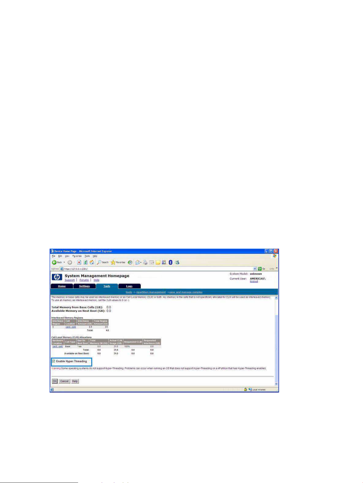
4. Verify success by rebooting to the EFI Shell again and issuing another cpuconfig threads
command, which should indicate ON.
Enable hyperthreading using Partition Manager
Another way to enable hyperthreading (on partitionable servers only), is to use the Partition
Manager partitioning tool. Partition Manager is a Web-based application for system administrators
that provides a convenient GUI for creating, configuring, and managing the hard partitions
(nPartitions) on an HP Integrity server.
To enable hyperthreading on partitionable HP Integrity servers where the OS and system
management tools have already been installed and upgraded to their latest versions, complete
the following steps:
1. On the management station or local nPartition desktop, double-click the HP System
Management Homepage (SMH) icon. This icon is added to the desktop by the SMH installer.
It is a link to the System Management Homepage on the local system. You do not need
administrative access (normal Windows login accounts should allow access to SMH). If the
icon is not on the desktop, or has been deleted somehow, you can also access SMH using
the following URL: https://localhost:2381
2. When you are logged in to SMH, go to the Tools tab and click View and Manage Complex
in the “nPartition Management” category. If Partition Manager is running on the partitionable
system being managed, you are immediately logged into the local complex, and all views
displayed are of that local complex. If Partition Manager is running on a management station
used to access the server remotely, a screen for logging into a remote partition appears, and
you must enter an IP address and password to continue. For context-sensitive help at any
time, click the Help button.
3. In the lower left corner of the screen, select Enable hyperthreading and click OK.
Figure 2-13 Enabling hyperthreading in the Partition Manager
56 Installing the OS
Page 57

3 Installing the Management Tools
This chapter describes the installation of tools and applications used to manage your Integrity
server.
Installing System Management Homepage
This section describes the installation of System Management Homepage (SMH) on Integrity
servers.
Configure SMH after Support Pack installation
When you install SMH using the Support Pack it, is configured using the default security settings.
Use the SMH online help for information on the security settings. To access the help:
1. Click Help on the System Management Homepage.
2. Click System Management Homepage Help.
3. On the left navigation bar, select Settings Tab > Security.
Install SMH separately
If SMH is not installed from the Support Pack, install it using the HP Smart Setup interface and
manually configure the security settings, using the following instructions:
1. Insert the HP Smart Setup media into the CD drive. The Smart Setup media autorun menu
loads and executes.
2. Click Agree to accept the license agreement and display the software and drivers window.
3. Go to the Software tab.
4. Select the server model from the list to display the software available.
5. Select System Management.
6. Click HP System Management Homepage for Windows. The Smart Setup download page
appears.
7. Click download >> to start the installation. The HP Package Setup screen appears.
Figure 3-1 HP System Management Homepage for Windows
8. Click Install.
9. Monitor the installation process as the files are copied to the server hard disk. The HP System
Management Homepage Setup wizard appears.
10. Click Next. The Operating System Groups dialog box appears.
Installing System Management Homepage 57
Page 58

11. To add HP SMH group names:
a. In the Group Name field, enter a name for the operating system group.
b. Select an operating level to include: Administrator, Operator, or User.
12. Click Add. The group name is added. You can add a maximum of five entries for each group
level.
13. Click Next to continue. The User Access dialog box appears. Use it to configure HP SMH
for the following access types:
• Select Anonymous Access to enable anonymous access to unsecured pages.
• Select Local Access Anonymous or Local Access Administrator to set up HP SMH to
automatically grant local IP addresses at the selected access level.
CAUTION: Selecting local access with Administrator privileges provides any users
with access to the local console full access without prompting them for a user name or
password.
14. Click Next. The Trust Mode dialog box appears.
NOTE: Next you must select the level of security you want to provide. There are two trust
modes available: Trust by Certificate or Trust by Name. Trust by Certificate security is
described in step 15. Trust by Name security is described in step 16. You must perform one
of these steps only – not both of them. After completing step 15 or step 16, continue with
step 17.
IMPORTANT: There is another trust mode available called Trust All. HP does not
recommend using this option because it sets up HP SMH to accept certain requests from
any server and leaves your system vulnerable to security attacks.
15. To select the Trust by Certificate security mode from the Trust Mode dialog box, complete
the following steps:
a. Click Next. The Trusted Certificates dialog box appears. The Trusted Certificates dialog
box allows trusted certificate files to be added to the Trusted Certificate List.
b. Click Add File. The Add File dialog box appears. Select any certificates to be included
in the Trusted Certificate List. Click OK to select another file, or click Cancel to close
the dialog box. The Trusted Certificate List appears.
c. Click Next. The IP Binding dialog box appears.
d. Enter the name or IP address of the server whose certificate you want to import.
e. Click Get Cert. The certificate information appears.
f. Verify the certificate information. To add this certificate to the Trusted Certificate List,
click Accept, or click Cancel if you do not want to add it to the Trusted Certificate List.
The Trusted Certificate List appears.
g. Click Next. The IP Binding dialog box appears. Click Back to return to the Trust Mode
dialog box.
h. Go to step 17 and continue from there.
16. To select the Trust by Name security mode from the Trust Mode dialog box, complete the
following steps:
a. Select Trust By Name.
b. Click Next. The Trusted Server dialog box appears.
c. Enter the names of the servers you want to trust and click Add.
d. Click Next. The IP Binding dialog box appears.
58 Installing the Management Tools
Page 59

17. Select IP Binding to enable the subnet IP address and netmask. The IP Binding dialog box
enables you to bind to specific IP addresses that match a specific subnet IP address or
netmask. It restricts the subnet you want to manage.
a. Enter the subnet IP address in the designated field.
b. Enter the netmask in the designated field.
c. Click Add, and the subnet IP address or netmask appears in the dialog box.
d. To delete a subnet IP address or netmask from the dialog box, select it and click Delete.
The subnet IP address or netmask is removed from the dialog box.
18. Click Next. The IP Restricted Login dialog box appears. The IP Restricted Login dialog box
enables you to select specific IP addresses or IP address ranges to include or exclude from
gaining login access. Although optional, HP SMH can restrict login access based on the IP
addresses of the machine attempting to gain access.
19. Select IP Restricted Logins, and click Next. The IP Address to Include dialog box appears.
This dialog box enables you to specify the IP address or IP address ranges to grant login
access permission. If the Inclusion list contains IP addresses, then only those IP addresses
are enabled for login privileges. If no IP addresses are in the Inclusion list, then login
privileges are permitted to all IP addresses that are not in the Exclusion list.
a. In the Include field, enter a beginning IP address to which you want to grant login
access.
b. In the To field, enter an ending IP address to which you want to grant login access. All
IP address that fall between the beginning and ending IP addresses are granted login
access.
c. Click Add. The IP address or IP address range is added to the Inclusion list.
d. To delete an IP address or IP address range, select it and click Delete. The IP address
or IP address range is deleted from the Inclusion list.
20. Click Close at the end of installation.
Initializing SMH
After you install and configure HP SMH, a process to create a private key and corresponding
self-signed Base64-encoded certificate is initiated. This certificate is a Base64-encoded PEM file.
The public and private keys are stored in the \hp\sslshare directory of the system drive. To
protect the key, this subdirectory is only accessible to administrators if the file system allows
such security. For private key security reasons, HP recommends that you install Windows
installations of HP SMH on the NT file system (NTFS).
IMPORTANT: For Windows operating systems, the file system must be NTFS for the private
key to have administrator-only access through the file. If the private key is compromised, the
administrator can delete the \hp\sslshare\cert.pem file and restart the server. This causes
HP SMH to generate a new certificate and private key.
NOTE: Certificate and private key generation only occur the first time HP SMH is started or
when no certificate and key pair exist. You can use a certificate from a certificate authority (CA),
such as Verisign or Entrust, to replace a self-generated certificate. These certificate and key files
are shared with other HP management software, such as HP Systems Insight Manager.
Installing the management agents
Install all of the agents using the automated Windows installer described in this section. If you
already have an earlier version of the management agents installed, this procedure automatically
upgrades the installed agents to the latest version.
Installing the management agents 59
Page 60
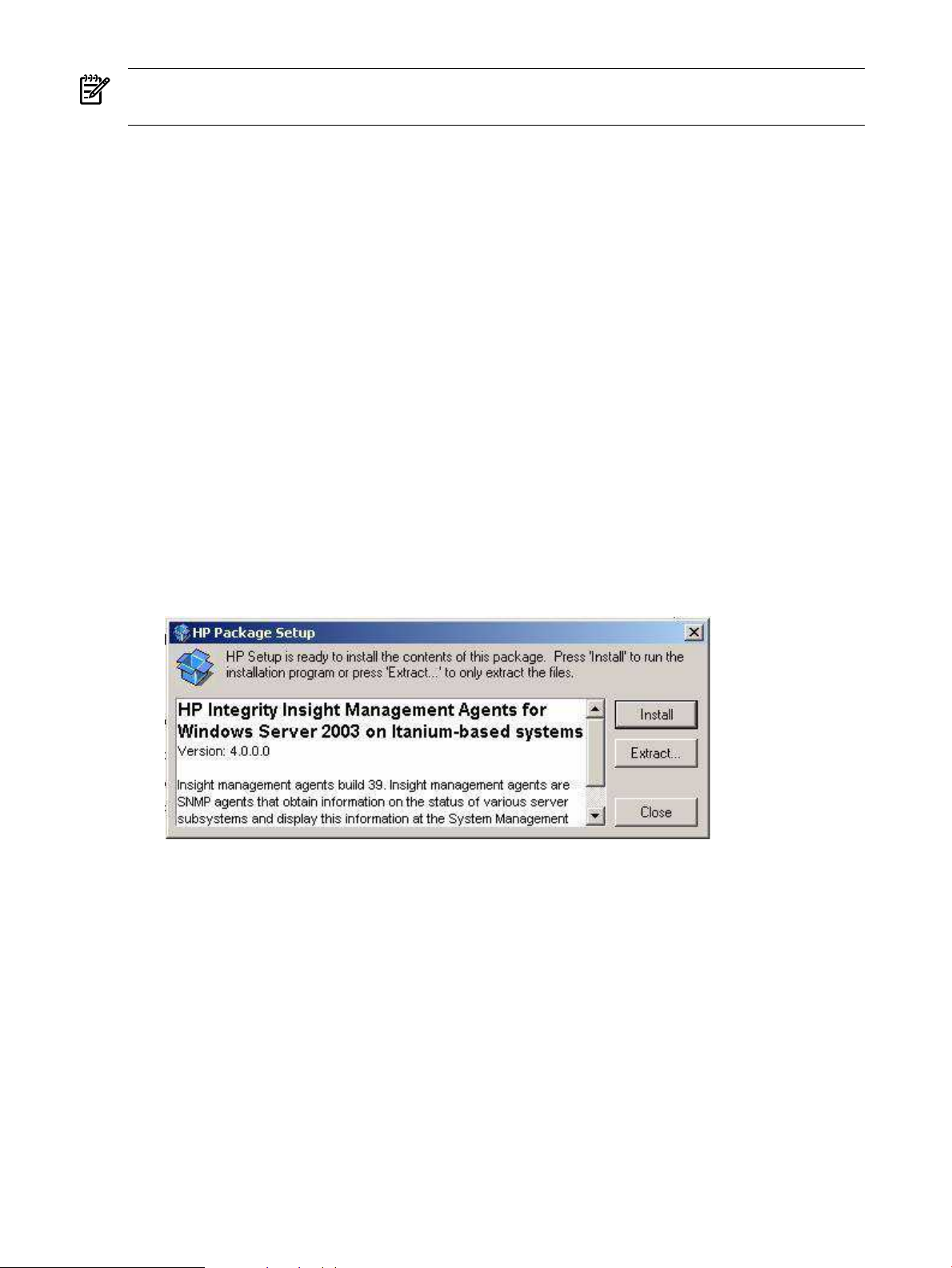
NOTE: Do not install any HP management agents until you have installed and configured the
TCP/IP and SNMP protocols.
Configure management agents after Support Pack installation
Agents are automatically activated when they are installed (except for the Clustering Information
agents). Inactive agents remain installed but are dormant until you activate them again. For
instructions on configuring an agent or making it inactive, see “Activating and configuring
agents” (page 60).
Install management agents from Smart Setup media
To install the HP management agents using the Windows installer, complete the following steps:
1. Insert the HP Smart Setup media into the CD drive. The Smart Setup media autorun menu
loads and executes.
2. Click Agree to accept the license agreement and display the software and drivers window.
3. Go to the Software tab.
4. Select the server model from the list, to display the software available.
5. Select System Management.
6. Click HP Insight Management Agents (Windows Server 2003 on Itanium-based systems.
The Smart Setup download page appears.
7. Click download >> to start the installation. The HP Package Setup page appears.
Figure 3-2 HP Insight Management Agents for Windows Server 2003 on Itanium-based
systems
8. Click Install. The HP Setup screen appears.
9. Monitor the installation process as the files are copied to the server hard disk. After the files
are copied, the installation wizard prompts you to start the agents.
10. Click Close at the end of the installation.
11. Open the Windows Control Panel and verify that the HP management applet has been
installed.
12. Open Windows Services and verify that the agent services are installed and running.
Activating and configuring agents
Configuring and activating agents comprises the following tasks:
Activating agents
Activate and deactivate selected agents from the Windows Control Panel. To activate or deactivate
an agent, complete the following steps:
60 Installing the Management Tools
Page 61
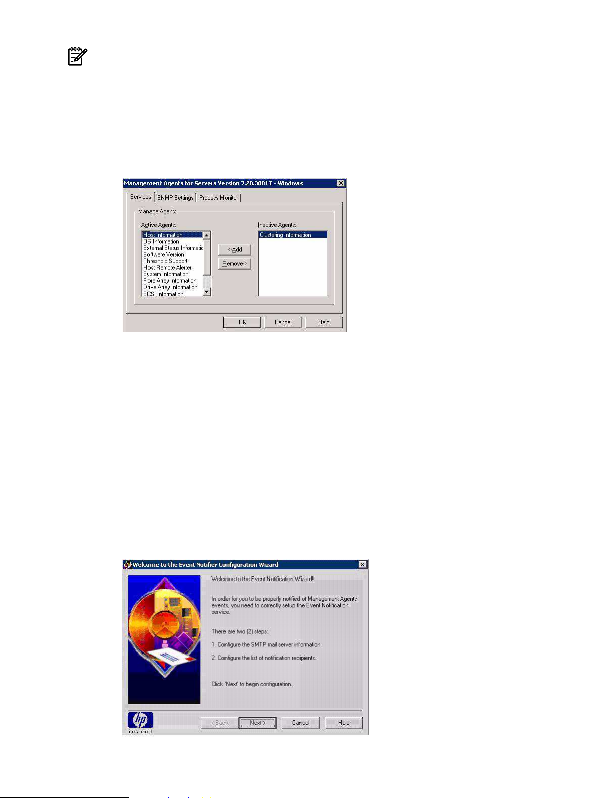
NOTE: You must have Administrator rights to access the management agents from the Windows
Control Panel.
1. Open the Windows Control Panel and select HP Management Agents for Integrity Servers.
The installed agents are listed in the window. All agents except clustering information are
activated at time of installation.
2. Click the Services tab.
Figure 3-3 Services tab screen
3. Select an agent from either column to change the active or inactive status.
4. Click either Add or Remove to change the status of the selected agent.
5. Click OK when you have made all required status changes.
Configuring the event notifier
The event notifier monitors agent events and sends email notifications when designated events
occur. Use the event notifier configuration wizard to configure email addresses, entity types,
and events triggers.
Use the configuration wizard to completely configure the notification service.
To configure the event notifier, complete the following steps:
1. From Windows, select Start > HP Insight Management Agents > Event Notifier
Configuration Wizard. A Welcome screen appears.
Figure 3-4 Welcome message
Installing the management agents 61
Page 62
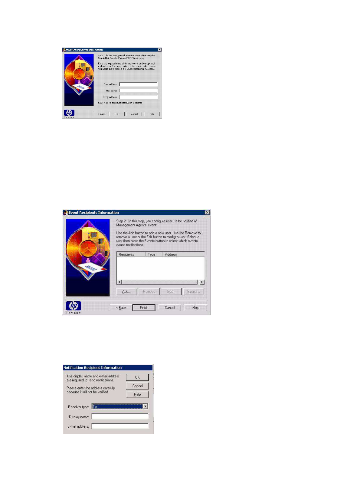
2. Click Next to access the SMTP information window.
Figure 3-5 Mail (SMTP) server information
3. Enter a valid email address in the From address field or leave it blank.
4. Enter the name of the SMTP mail server you are using in the Mail server field.
You must enter a valid server address to continue with the setup process. The wizard checks
the SMTP mail server address you entered to see if it can be accessed. If the wizard cannot
access the mail server address, it displays a warning message and returns you to the SMTP
server address window.
5. Click Next. The Events recipients information window appears.
Figure 3-6 Event recipients information
In this window, add users designated to receive event messages.
6. Click Add to add a new user or click Edit to edit the properties for an existing user.
Figure 3-7 Adding a new user
7. Select the email recipient type from the Receiver type drop-down list.
62 Installing the Management Tools
Page 63
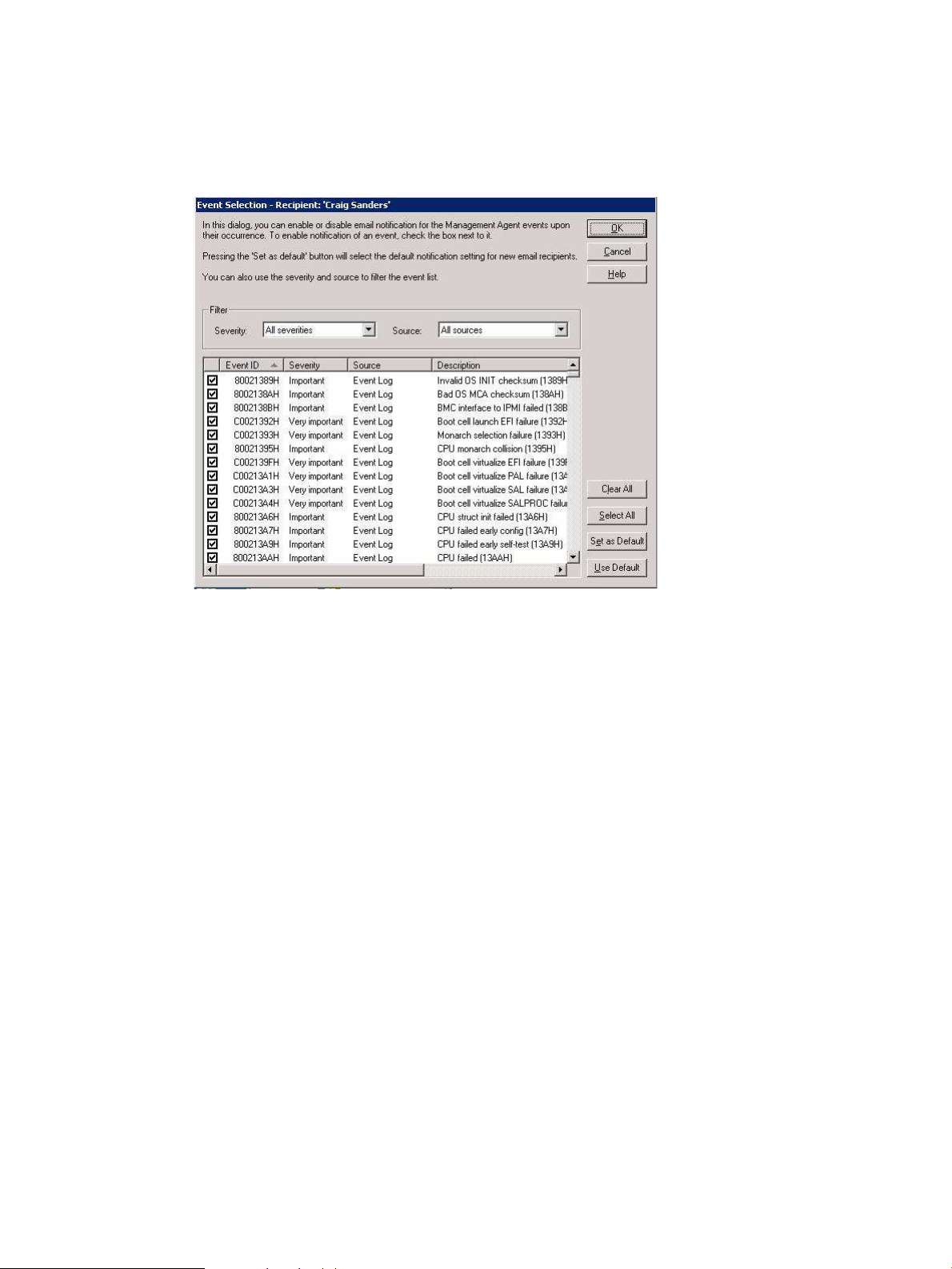
8. Click OK to return to the recipient information window.
9. Select a user name and click Edit to edit user properties, or select a user name and click
Delete to remove a user.
10. Click Events to display the Event Selection window.
Figure 3-8 Event selection window
11. Use the severity and source filter fields to view selected events only. The event severity
levels, source, and message are not user-configurable.
12. Click the check box to enable an event or disable email notification for an event.
13. Click Use Default to load the current default event notification settings.
14. Click Set Default to set and save the current notification settings as the default values.
15. Click OK when you are done, returning to the Event Recipient Information window.
16. Click Finish to close the window.
Setting the agent SNMP data collection interval
Active agents poll server devices at preset intervals, collecting management SNMP data.
To set the agent SNMP data collection interval, complete the following steps:
1. Open the Windows Control Panel and double-click HP Management Agents.
The installed agents are listed in the window. All agents except clustering information are
activated at time of installation.
2. Click the SNMP Settings tab.
Installing the management agents 63
Page 64

Figure 3-9 SNMP Settings tab
3. Select a time interval for SNMP data collection from the Data Collection Interval list box.
4. Click the Send Test Trap button (available only if the HP host agent is active) to send a test
trap.
5. Click Clear All Thresholds to clear all current SNMP trap threshold values.
6. Click OK.
NOTE: Windows Server 2003 on the HP Integrity server does not support the following
SNMP operations:
• Enable Remote Reboot
• Enable the Application Exception Trap
• Disable Telnet Detection
• Disable Rack Infrastructure Traps
Monitoring server processes
Use the Process Monitor tab to set up SNMP traps generated when a process starts, stops, or
both.
To enable agent process monitoring, complete the following steps:
1. Open the Windows Control Panel and select Start Menu > Control Panel > HP Insight
Management Agents. The Management Agents for Servers Version Number window
appears.
2. Click the Process Monitor tab.
Figure 3-10 Process Monitor tab
64 Installing the Management Tools
Page 65
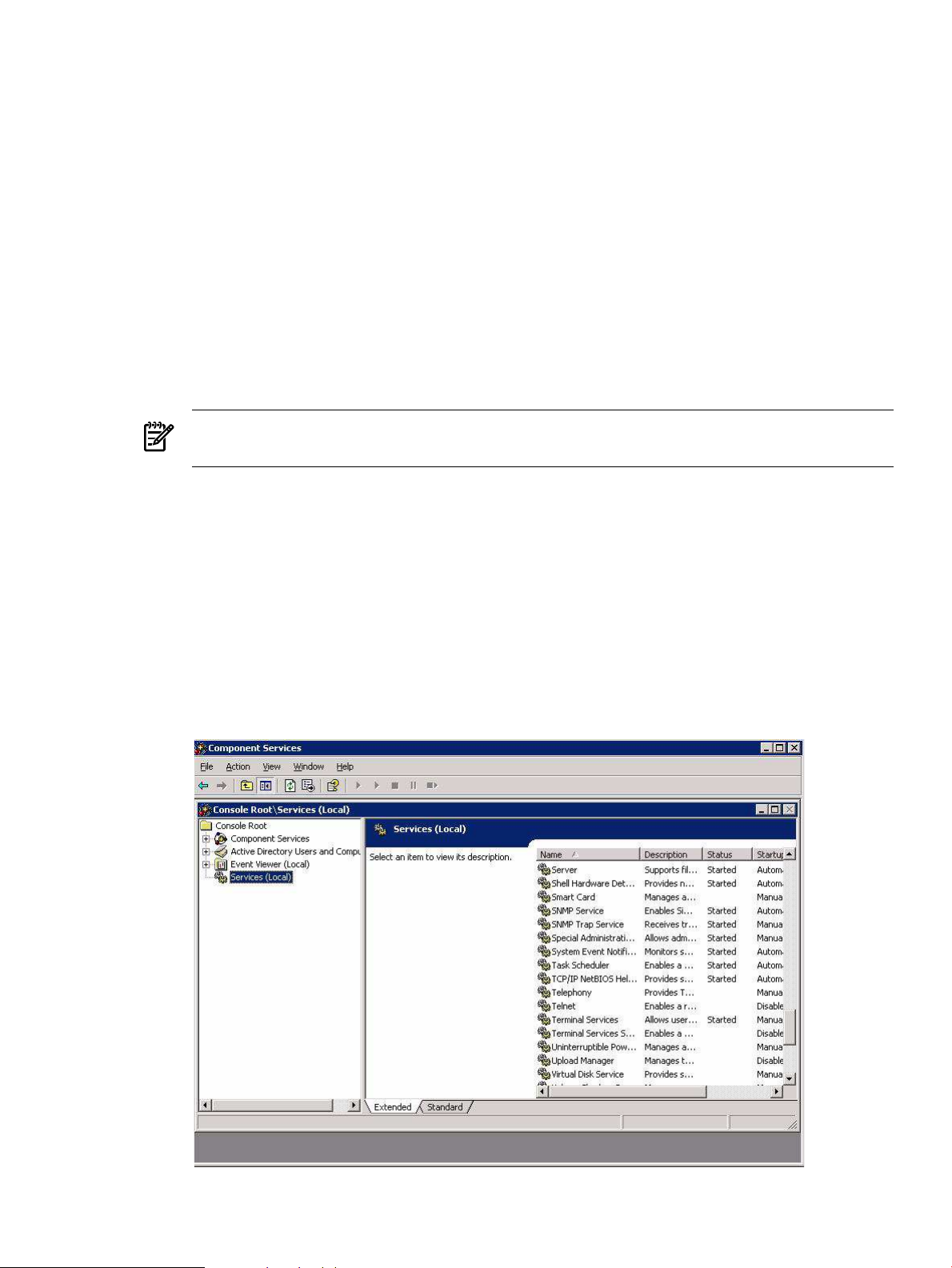
This tab displays all currently active (running) server processes. The Monitor Option column
displays the current monitoring status for each process listed.
3. Select the process you want to change the monitoring status for.
4. Change monitoring status by clicking one of these radio buttons:
• None — No SNMP traps are generated for this process.
• Start — An SNMP trap is generated when this process starts.
• Stop — An SNMP trap is generated when this process stops.
• Start & Stop — An SNMP trap is generated when this process starts or stops.
• Add — Add a new process to the monitor. Enter the name of the new process, then
click Apply to add the process.
• Delete — Highlight a process in the list, and select Delete to delete the process.
5. Click Add to add a new process, then enter the name of the process.
6. Click Delete to delete a process selected from the list.
7. Click OK to confirm.
NOTE: You can only delete processes that a user has created. The Delete button is disabled
for system default processes.
8. Click OK when you are done configuring process monitoring.
Sending SNMP traps to management applications via IP
Configure SNMP services with a specific IP addresses to send SNMP traps to an SNMP
management application with an IP address.
To configure management agents with a management console IP, complete the following steps:
1. From the Start menu, select Start > Settings > Control Panel > Administrative Tools >
Component Services. The Component Services window appears.
2. Click Services (Local).
Figure 3-11 Component Services window
Installing the management agents 65
Page 66

3. From the list of services, double-click SNMP Service. The SNMP Service Properties (Local
Computer) window appears.
4. Click the Security tab.
5. Click the Traps tab.
Figure 3-12 SNMP traps tab
6. In the Community name field, if a community name already exists, select it. If one does not
exist, enter a community name and click Add to List.
NOTE: The default community string for HP Insight Manager is public. If you enter a
different community string here, enter the same string on the management console that is
responsible for the system. HP recommends not using the string public because it is the
default value, commonly used, and can present a security risk.
7. Under the Traps Destinations list, click Add. The SNMP Service Configuration window
appears.
Figure 3-13 SNMP service configuration
8. In the Host name, IP or IPX Address field, enter the IP address of the management console.
This address identifies the management console to receive the alert when the server agents
detect a significant event.
9. Add 127.0.0.1 as a trap destination if it is not already listed. You must do this to enable the
loopback service.
10. Click Add, then OK.
Installing partition management tools
This section is an overview of the installation and use of the nPartition Commands Bundle and
nPartition Manager Bundle. You must install the nPartition Commands Bundle before the
66 Installing the Management Tools
Page 67

nPartition Manager Bundle. For more information about installing and using Partition Manager,
see the nPartition Guide, located on the HP Smart Setup media at:
\contents\doc\en_us\npartition.pdf
Install nPartition Commands Bundle from the Smart Setup media
This section describes the tasks you need to complete before you install the nPartition Commands
Bundle from the Smart Setup media.
1. Install all the OS fixes and security fixes on the Smart Update media. The Smart Update
DVD is part of the Integrity Essentials Foundation Pack kit, along with the Smart Setup CD.
To verify that all fixes were installed, select Control Panel > Add/Remove Programs and
scan the list of installed software.
2. Install the Integrity Support Pack from the Smart Setup CD. The Integrity Support Pack
includes software, drivers, and management agents optimized for Integrity servers. Integrity
Support Pack also installs some of the components needed to run nPartition commands and
starts them as services.
To install the nPartition Commands Bundle, complete the following steps:
1. Insert the Smart Setup CD and click the Software tab.
2. In the left column, click the model number of the target server.
3. In the left column of the next page, click the Partitioning Tools link.
4. In the Partitioning Tools section, click one of the following:
• If you are installing onto a 32-bit client machine that will be used to administer the
target server, click HP nPartition Commands Bundle for Windows XP or Windows
Server 2000/2003.
• If you are installing onto the target server itself, click HP nPartition Commands Bundle
for Windows Server 2003 on Itanium-based systems.
5. At the top of the next page, click the Download button.
6. In the File Download window, click Run.
7. In the Security Warning window, click Run.
8. In the HP Package Setup window, click Install.
9. In the command window, press any key to begin the installation.
10. When the installation finishes, press any key again to exit and close the command window.
Install Partition Manager Bundle from the Smart Setup media
Before installing the Partition Manager Bundle, you must install the nPartition Commands
Bundle, as described in the previous section. See the nPartition Guide for detailed information
on the installation and use of the Partition Manager tools.
To install the nPartition Manager Bundle, complete the following steps:
1. Insert the Smart Setup CD and click the Software tab.
2. In the left column, click the model number of the target server.
3. In the left column of the next page, click on the Partitioning Tools link.
4. In the “Partitioning Tools” section, click on HP Partition Manager Bundle for Windows.
5. At the top of the next page, click on the Download button.
6. In the File Download window, click Run.
7. In the Security Warning window, click Run.
8. In the HP Package Setup window, click Install.
9. In the command window, press any key to begin the installation.
10. In the HP System Management Homepage (SMH) installation wizard screen, click Next.
Installing partition management tools 67
Page 68

11. Through the next several screens, configure SMH administrator and security settings as
prompted, and the SMH installation begins.
12. When the SMH installation finishes, click Next in the HP Servlet Container for SMH wizard
screen. Then click Next two more times to begin the servlet container installation.
13. Click Finish to complete the servlet container installation.
14. The HP Partition Manager installation starts next. When it finishes, press any key in the
command window to exit.
15. Verify that the installation succeeded.
Verifying the installation
To verify correct server configuration and software installation, perform the following simple
tests:
Verify nPartition commands
1. Perform a local management test by opening a command prompt window and issuing the
following command:
C:\Documents and Settings> parstatus -X
If you run this command on an nPartition, it displays information about the local server’s
nPartition configuration. No error messages should be returned. If you run this command
on a non-nPartition, however, the following message should display (which is the expected
response in this situation, and not an error):
Error: unsupported platform
2. To verify access and communication with the server, as well as installation of the nPartition
commands, enter the following command:
C:\Windows> parstatus -X -h <mp> -g <password>
where <mp> is either the IP address or the host name of the server MP, and <password>
is the MP IPMI password. This command should result in the display of approximately 10
server attributes, including the server name, model number, and so on. You might experience
a delay of a few seconds, or even a minute or more, depending on network distance between
the management station and the server.
NOTE: The command in step 2 works only with the IPMI over LAN connection method.
If you are using WBEM/WMI, substitute the -u option for the -g option shown in step 2.
This also requires copying the WBEM certificate for the remote nPartition into the WBEM
trusted certificate store on the system where the command is being run.
Verify Partition Manager installation
Partition Manager depends on the presence of the nPartition commands. Before proceeding, first
check that the commands are installed correctly by following the procedure in the previous
section.
1. Verify the Partition Manager installation by launching a web browser and logging in to
SMH on the system where Partition Manager is installed. For example, if you are testing on
the local server, the URL would be https://localhost:2381.
2. To continue the verification at the SMH, on the Tools tab, click Partition Manager. If Partition
Manager is running, you will go directly to the top-level view of the local complex (no
additional login is required). If Partition Manager is not running on an nPartition, you are
presented with a dialog asking for one of the following:
68 Installing the Management Tools
Page 69

• The host name and IP address and the login/password for a remote nPartition (for
remote WBEM connections)
• The host name and IP address and the IPMI password of an MP (for remote IPMI
connections)
If you are running Partition Manager on an nPartition, skip steps 3 and 4 and go directly to
the step 5 where you verify correct operation of the Partition Manager.
3. In order to test remote WBEM connections, do the following:
a. Copy the remote nPartition WBEM certificate into the local WBEM trusted certificate
store.
b. Enter the host name and IP address of the remote nPartition that you want to connect
to, along with an account and password with administrative privileges on the remote
nPartition in the top half of the Partition Manager login screen.
c. Click OK.
4. In order to test remote IPMI connections, do the following:
a. Enter the host name and IP address of the remote management processor that you want
to connect to, along with the IPMI password for that MP in the bottom half of the
Partition Manager login screen.
b. Click OK.
5. Verify correct operation of Partition Manager.
After you log in to Partition Manager, the following message should appear for several
seconds to a minute or so:
Loading complex information
After that, Partition Manager should display top-level information about the complex,
including all currently configured nPartitions and their associated cells and I/O chassis.
6. When Partition Manager is up and running, verify that the complex information looks correct
and that no error messages are displayed. For example, in the Action menu on the right side
of the screen, click Complex to expand the complex-level submenu. Click Show Complex
Details to display a complete listing of the complex configuration. Verify that this information
is correct, and that no error messages are displayed. Click OK to close the Complex Details
window.
7. In the same Complex menu, click Clear All LEDs. A dialog box should appear, stating that
the command ran successfully. If possible, verify that all server LEDs are now off by looking
at the server.
If these tests do not give the desired results, you can perform additional tests to help pinpoint
the problem. Consult the nPartition Guide, located on the HP Smart Setup media at
\contents\doc\en_us\npartition.pdf, for more information.
Installing partition management tools 69
Page 70

70
Page 71

4 Performing hot-plug operations
This chapter describes adding and removing PCI cards on HP Integrity servers. Adding a card
to your system is called a “hot-plug addition,” and removing a card is called a “hot-plug deletion.”
IMPORTANT: HP Integrity rx1620, rx2620, rx2660, BL860c, and BL870c servers do not support
PCI card hot-plug addition or deletion.
Before you begin
Review the following terms before beginning hot-plug operations:
• Attention button Use the attention button to initiate hot-plug operations. The location of
the attention button varies, depending on the server. For example, HP Integrity rx7620,
rx7640, rx8620, and rx8640 servers have a white bell-shaped image button, located at the
top rear of the PCI slot. To access, remove the button cover. HP Integrity rx3600, rx4640,
rx6600, BL860c, and BL870c servers have a maroon-colored button on the top of the PCI slot
separator, just below the manual retention latch (MRL). HP Integrity Superdome servers do
not have attention buttons.
• MRL latch The MRL sensor is activated by the manual retention latch (MRL). When the
MRL is open, the power is turned off to the slot to prevent electrical damage to the card and
the system. HP Integrity rx7620, rx7640, rx8620, and rx8640 servers have a blue lever at the
top rear of the PCI slot. The HP Integrity rx4640 server has a black lever at the rear of the
PCI slot and a black latch at the rear of the PCI slot separator. HP Integrity rx3600 and rx6600
servers have a black latch on top of the PCI slot that you must press down then pull upward
to activate. HP Integrity Superdome servers do not have MRLs.
• Online replacement Windows does not natively support I/O card online replacement.
Such an action requires two steps: hot-plug deletion first, and then hot-plug addition.
Therefore, some applications will notice the loss of an adapter.
• Power indicator The green power indicator LED is located at the top of the slot separator
on all HP Integrity servers. When this indicator is on (or flashing), the slot is powered and
should not be disturbed. When the indicator is off, you can safely add a PCI card to and
remove it from the slot.
If you perform hot-plug additions or deletions on the HP Integrity server and you do not achieve
the expected results, verify installation of the driver.
To verify driver installation on HP Integrity mid-range or high-end servers, complete the following
steps:
1. Launch the Windows Device Manager and expand the system devices. Right-click HPCSR
OpRegion Driver. Then click Properties and go to the Driver tab. The driver should be
named hpcsr.sys, Version 1.1.0.0, dated 6/13/03. If it is not, you must update the driver.
2. Open the Online Reference page on the desktop.
3. Click OEM Drivers.
4. In the Description column, click HP (Hotplug) Region Driver. This starts the hot-plug driver
update.
5. Click Yes to install the driver.
Whenever you activate a PCI slot that is already powered on, its solid orange attention LED light
turns on, indicating an error. Also, if you try to activate a slot that is not occupied, it flashes the
attention LED to identify that slot. This is expected behavior, and not an error. When the PCI
slot is powered off, the power LED for that slot will be off, and the attention LED will be either
off or blinking.
Before you begin 71
Page 72

NOTE: You cannot perform a hot-plug addition for some cards unless they replace the same
type card in the slot. You cannot hot-add them in a new installation. Although no damage to the
server occurs if you attempt a hot-plug addition with these cards, they will not function until
the next reboot. The following table lists the PCI cards that do not support hot-plug addition.
Table 4-1 PCI cards that do not support hot-plug addition
PCI CARD
Supported
(replace)
In addition, rx3600 and rx6600 PCI Express-based Integrity servers have the following limitations
in hot-plug functionality:
• Hot-plug operations on PCI Express slots 3 and 4 are currently disabled.
• Regarding hot-plug operations on PCI-X slots 7, 8, 9, and 10: Doorbell functionality can be
intermittent. You must press the attention button until the power indicator LED is either
solidly on or off.
Adding a PCI card
This section describes how to add a PCI card (called a hot-plug addition) on HP Integrity servers
running Windows Server 2003.
Before performing hot-plug additions or deletions to HP Integrity servers, ensure the following:
• On HP Integrity rx7620, rx7640, rx8620, rx8640, and Superdome servers, you must install
the latest version of the OpRegion driver. This driver is not required on the rx4640 server.
• HP Integrity rx4640 server slots 2 to 3 and 4 to 5 are shared PCI hot-plug slots. For optimal
hot-plug operation, use the same type of PCI cards in these shared slots. For example, if a
PCI-X 133 MHz card is in slot 4, the insertion of a PCI 66 MHz card in slot 5 will fail because
the slot has been set at 133 MHz. However, if a PCI-X 66 MHz card is in slot 3, the insertion
of a PCI-X 133 MHz in slot 2 will be successful, although both cards will run at 66 MHz. The
rx7620 and rx8620 do not have shared slots and are therefore not subject to these restrictions.
• Ensure that the server has the latest version of the system firmware installed.
SA5300SA6404SA6402Hot-Plug Operation
USB & VGA Graphics Combo Cards I
and II
(A6869A and A6869B)
NoNoYesYesYeshot-plug addition
NoNoNoNoNohot-plug addition (new)
Hardware interface for all HP Integrity servers except Superdome
To perform hot-plug additions using the server hardware interface for all HP Integrity servers
except Superdome, complete the following steps:
1. Locate an empty slot.
2. If the power light is on for the slot, press the attention button to start the power-off sequence.
(If the power light is not on, you do not need to press the attention button.) The power LED
will blink for 5 seconds. While the power LED is flashing, you can cancel the power-off
sequence by pressing the attention button again.
72 Performing hot-plug operations
Page 73

NOTE: HP Integrity rx7620, rx7640, rx8620, and rx8640 servers have a white bell-shaped
image button located at the top rear of the PCI slot. To access, remove the button cover. HP
Integrity rx3600, rx4640, and rx6600 servers have a maroon-colored button on the top of the
PCI slot separator, just below the manual retention latch (MRL). HP Integrity Superdome
servers do not have attention buttons.
3. Wait for the slot to power off (green power LED will turn off).
4. Open the MRL.
NOTE: The MRL sensor is activated by the MRL. When the MRL is open, the power is
turned off to the slot to prevent electrical damage to the card and the system. HP Integrity
rx7620, rx7640, rx8620, and rx8640 servers have a blue lever at the top rear of the PCI slot.
The HP Integrity rx4640 server has a black lever at the rear of the PCI slot and a black latch
at the rear of the PCI slot separator. HP Integrity rx3600 and rx6600 servers have a black
latch on top of the PCI slot that you must press down then pull upward to activate. HP
Integrity Superdome servers do not have MRL latches.
5. Add the PCI card to the slot.
6. Close the MRL.
7. Press the attention button of the slot. The power LED will again blink for 5 seconds. While
the power LED is blinking, you can abort the request by pressing the attention button.
Windows loads and starts the drivers for all functions of the device or prompts you to install
the drivers for the new card. The system should then begin using the device normally.
8. Check the Windows Device Manager for the device just installed. If the device is not present,
the addition failed.
NOTE: When performing hot-plug additions with a Smart Array P600 controller, you might
see the following error generated by the SecurePath Agent in the Application event log:
CreateFileA(\) failed: 3
However, because SecurePath does not actually manage the controller, and because the device
is detected after a couple of minutes and handled properly by the agent, you can safely ignore
this error.
Hardware interface for Superdome servers
To perform hot-plug additions using the Superdome hardware interface, complete the following
steps:
1. Locate an empty slot. Note the cabinet number, I/O bay number, I/O chassis number, and
the PCI slot number. All are marked on the cabinet or I/O chassis.
2. Insert the card into the slot. Power should be off on all unused slots, but check power LED
before making the insertion.
3. From the MP command window, enter the pciolad command. A screen similar to the
following appears:
This command initiates the activation or deactivation of a PCI card.
Note: Activate is equivalent to Add/Insert, and
Deactivate is equivalent to Remove/Eject.
Do you want to Activate or Deactivate a PC card (A,D): a
Enter cabinet number: w
Enter IO bay number: x
Enter IO chassis number: y
Enter PCI slot number: z
Adding a PCI card 73
Page 74

Activate PCI card in Cabinet w, IO Bay x, IO Chassis y,
PCI Slot z? (Y/[N]) y
Request to Activate PCI card sent to system. Check slot power LED.
MP:CM>
4. Check that the slot power LED (found by looking down through top of chassis) is not blinking,
indicating that the slot is powered. If the green LED is not on, the power to the slot is not
on and the addition of the card failed.
5. Check the Windows Device Manager for the device just installed. If the device is not present,
the addition failed.
Software interface
A software interface is not supported because Windows does not have a native interface for HP
hot-plug additions. The Microsoft Add Hardware Wizard and Scan for hardware changes features
are not sufficient to power and enable these cards.
Removing a PCI card
This section describes how to remove a PCI card (called a hot-plug deletion) on HP Integrity
servers running Windows Server 2003.
NOTE: The Windows software interface is the preferred method for hot-plug deletions. Use
this method instead of the hardware interface.
Software interface for all HP Integrity servers except Superdome
To perform hot-plug deletions using the server software interface for all HP Integrity servers
except Superdome, do the following:
1. Request that Windows remove the hardware by clicking the Safely Remove Hardware
launch icon in the bottom right corner of the screen. Windows notifies you when it is safe
to remove the card.
NOTE: If you remove the card before notification from Windows that it is safe to do so, a
machine check abort (MCA) occurs.
2. Open the manual retention latch (MRL).
3. Remove the card.
4. Close the MRL.
Software interface for Superdome servers
To perform hot-plug deletions using the Superdome software interface, do the following:
1. Request that Windows remove the hardware by clicking the Safely Remove Hardware
launch icon in the bottom right corner of the screen. Windows notifies you when it is safe
to remove the card.
NOTE: If you remove the card before notification from Windows that it is safe to do so, a
machine check abort (MCA) occurs.
2. Remove the card.
Hardware interface for all HP Integrity servers except Superdome
To perform hot-plug deletions using the server hardware interface for all HP Integrity servers
except Superdome, do the following:
74 Performing hot-plug operations
Page 75

1. Locate the slot of PCI card to delete.
2. Press the attention button for the slot. The power LED will begin flashing. During the 5
seconds that the power LED is flashing, you can abort the request by pressing the attention
button. When the green LED stops blinking and goes off, it is safe to remove the card.
NOTE: Do not remove the card before the LED stops blinking or a fatal machine check
alert (MCA) error occurs.
3. Open the manual retention latch (MRL).
4. Remove the card.
5. Close the MRL.
Hardware interface for Superdome servers
To perform hot-plug deletions using the Superdome hardware interface, do the following:
1. Locate the slot containing the card to be deleted. Note the cabinet number, I/O bay number,
I/O chassis number, and the PCI slot number. All are marked on the cabinet or I/O chassis.
2. From the MP command window, enter the pciolad command. A screen similar to the
following appears:
This command initiates the activation or deactivation of a PCI card.
Note: Activate is equivalent to Add/Insert, and
Deactivate is equivalent to Remove/Eject.
Do you want to Activate or Deactivate a PC card (A,D): d
Enter cabinet number: w
Enter IO bay number: x
Enter IO chassis number: y
Enter PCI slot number: z
Activate PCI card in Cabinet w, IO Bay x, IO Chassis y,
PCI Slot z? (Y/[N]) y
Request to Activate PCI card sent to system. Check slot power LED.
MP:CM>
3. Check that the slot power LED (found by looking down through top of chassis) is off. The
green LED becomes an orange blinking LED, indicating that the slot is not powered. If the
green LED is not off, the power to the slot is not off and the deletion of the card failed.
4. Remove the card.
Removing a PCI card 75
Page 76

76
Page 77

A Preparing the server for Microsoft SQL Server 2005
This appendix describes the server configuration tasks needed to install Microsoft SQL Server
2005.
SQL Server 2005 installation
This section is an overview of the steps needed to install SQL Server 2005. For further installation
and configuration information, see the SQL Server 2005 documentation.
1. Configure the server
• Set the system ACPI Config Flag to Windows.
• Verify that system nPartitions are set to 100% cell local memory (CLM) by using the
ParCLI parstatus command. Adjust the value to 100%, if necessary, using the
parmodify command (see the nPartition Guide on the Smart Setup media at
\contents\doc\en_us\npartition.pdf).
• Data Warehousing: For decision support and data warehousing, set the number of CPUs
to a higher number, such as four, up to the actual number of CPUs.
2. Configure SQL Server 2005
• Check affinity masks. By default these are set to zero. Set them to actual CPU
configurations for all CPUs using Spconfigure.
• Confirm the degree of parallelism settings:
1. a) If you have a large system (more than four CPUs), do not set this number to zero
using SPconfigure. Also, increase parallelism if you expect highly complex queries.
2. b) Online transaction processing (OLTP): For these workloads, set the level of
parallelism low (one query should not use more than one CPU, so set to 1).
3. Verify networking issues
• Confirm that you have enough network interface cards (NICs). If you have more than
10,000 packets/second on a NIC, add another NIC.
• Enable TCP and IP, and Rx and Tx checksum off-loading.
4. Verify storage/Fibre Channel HBAs:
• Maximum queue depth: Ensure that the Emulex driver options set in LPutil are equal
to or greater than the number of physical drives (default = 20).
• Maximum queue depth: For Qlogic NVRAM, ensure that the Sanblade execution throttle
setting is equal to or greater than the number of physical drives (default = 16).
• Enable write cache: It is important to have a cached log for the database.
Installing SQL Server from the command prompt
To install a standalone instance of SQL Server from the command prompt, do the following:
1. Insert the SQL Server 2005 installation media into the disk drive.
2. For instance-aware components (the Database Engine, SQL Server Agent, Analysis Services,
and Reporting Services) use the following syntax:
Start /wait <CD or DVD Drive>\setup.exe /qb INSTANCENAME=<InstanceName> ADDLOCAL=SQL_Engine,
SQL_Replication PIDKEY=<pidkey value with no "-"> SAPWD=<StrongPassword>
SQLACCOUNT=<DomainName\UserName> SQLPASSWORD=<DomainUserPassword>
AGTACCOUNT=<DomainName\UserName> AGTPASSWORD=<DomainUserPassword>
SQLBROWSERACCOUNT=<DomainName\UserName>
SQLBROWSERPASSWORD=<DomainUserPassword>
To install a clustered instance of SQL Server 2005 from the command prompt, do the following:
1. Insert the SQL Server 2005 installation media into the disk drive.
2. For a new failover cluster, use the following syntax:
Start /wait <DVD Drive>\setup.exe /qn VS=<VSName>
SQL Server 2005 installation 77
Page 78

INSTALLVS=SQL_Engine INSTANCENAME=<InstanceName>
ADDLOCAL=SQL_Engine,Client_Components ADDNODE=<NodeName1,NodeName2>
GROUP=<Diskgroup> IP=<IP,Networkname> ADMINPASSWORD=<StrongPassword>
SAPWD=<StrongPassord> INSTALLSQLDIR=<InstallationPath>
INSTALLSQLDATADIR=<ShareDrivePath> SQLACCOUNT=<domain\user>
SQLPASSWORD=<DomainUserPassword> AGTACCOUNT=<domain\user>
AGTPASSWORD=<DomainUserPassword>
Installing SQL Server from the GUI
To install SQL Server from the GUI, complete the following steps:
1. Insert the SQL Server 2005 DVD into the DVD drive. If the autorun feature does not launch
the installation program, navigate to the root of the DVD and launch the splash.hta file.
If you are installing from a network share, navigate to the network folder and launch
splash.hta.
2. From the autorun dialog, click Run the SQL Ser ver Installation Wizard.
3. On the End User License Agreement page, read the license agreement, and then accept the
licensing terms and conditions. Click Next.
4. On the SQL Server Component Update page, Setup installs software required for SQL Server
2005. To begin the component update process, click Install. To continue after the update
completes, click Finish.
5. On the Welcome page of the SQL Server Installation Wizard, click Next.
6. On the System Configuration Check (SCC) page, the installation computer is scanned for
conditions that may block setup. To interrupt the scan, click Stop. To display a list of check
items grouped by result, click Filter and then select a category from the drop-down list. To
view a report of SCC results, click Report and then select an option from the drop-down
list. To proceed with setup after the SCC scan completes, click Continue.
7. On the Registration Information page, enter the required information, then click Next.
8. On the Components to Install page, select the components to install. When you select SQL
Server or Analysis Services, if setup detects that you are installing to a virtual server, the
Install as a Virtual Server check box is enabled. You must select this option to install a
failover cluster.
9. If you clicked Advanced on the Components to Install page, the Feature Selection page
displays. On the Feature Selection page, select the program features to install using the
drop-down boxes. To install components to a custom directory, select the feature and then
click Browse. For more information about the functionality of this page, click Help.When
your feature selections are complete, click Next.
10. On the Instance Name page, select a default or named instance for the installation. If a default
or named instance is already installed and you select the existing instance for your installation,
setup upgrades it and provides you the option to install additional components. To install
a new default instance, a default instance must not already exist on the computer. To install
a new named instance, click Named Instance and then type a unique instance name in the
space provided.
11. Optionally, specify an individual account for each service. To specify an individual account
for each service, select Customize for each service account, select a service name from the
drop-down box, and then provide login credentials for the service. Then click Next.
12. On the Authentication Mode page, select the authentication mode to use for the SQL Server
installation. You must also enter and confirm a strong password for the system administrator
login. When you are finished, click Next.
13. To set separate collation settings for SQL Server and Analysis Services, select the Customize
for each service account check box. After you select the check box, a drop-down selection
box appears. Select a service from the drop-down selection box and then assign its collation.
Repeat for each service. Click Next.
14. If you selected Reporting Services as a feature to install, the Report Server Virtual Directories
page displays. Accept the default directory names, or specify a location for the directories.
78 Preparing the server for Microsoft SQL Server 2005
Page 79

For more information about this page, click Help at the bottom of the page. When you are
finished, click Next.
15. If you selected SQL Server Authentication, you must provide a user name and password
with administrative privileges for that instance. Confirm the Report Server Database Name.
Click Next.
16. If you selected Reporting Services as a feature, the Report Server Delivery Settings page
displays. Specify an SMTP server address and an email address to be used as the sender of
email messages from Report Server. When you are through, click Next.
17. On the Error Reporting page, optionally clear the check box to disable error reporting. For
more information about error reporting functionality, click Help at the bottom of the page.
When you are through, click Next.
18. On the Ready to Install page, review the summary of features and components for your SQL
Server installation. Click Install.
19. On the Installation Progress page, you can monitor installation progress as setup proceeds.
To view the log file for a component during installation, click the product or status name
on the Installation Progress page.
20. On the Completing the Microsoft SQL Server Installation Wizard page, you can view the
setup summary log by clicking the link provided. To exit the SQL Server Installation Wizard,
click Finish.
21. If prompted, restart the computer. It is important to read the message from the setup program
when you are done with installation. Failure to restart the computer can cause failures when
you run the setup program in the future.
SQL Server 2005 installation 79
Page 80

80
Page 81

B EFI Utilities
This appendix provides an overview of the EFI Extensible Firmware Interface (EFI) and the
EFI-Based Setup Utility (EBSU). The EFI provides access to the server at a pre-operating system
, which enables you to flash the firmware, partition the hard disk, install diagnostic tools, configure
storage controllers, and run other EFI utilities.
Introduction to EFI
The Extensible Firmware Interface (EFI) is an interface between the operating system, the firmware,
and the hardware. EFI serves the same purpose on Itanium-based computers as BIOS does on
x86-based computers. EFI provides a standard environment for running preboot applications
and for booting the OS.
HP Integrity servers use EFI to initialize the platform firmware and load the OS. After the system
is initialized, EFI provides two interfaces with which you can interact:
• EFI Boot Manager
• EFI Shell
EFI Boot Manager
First displayed when you power on the server, the EFI Boot Manager provides a menu-based
interface with options for booting the OS, loading EFI applications, configuring the server, and
other preboot operations. You use arrow keys to traverse menus.
EFI Shell
Figure B-1 EFI Boot Manager
Available as a selection from the EFI Boot Manager, the EFI Shell provides a command-line
interface from which you can get information about the system, install an OS, boot the OS, execute
batch scripts, launch EFI applications, load EFI drivers, and manage files and system variables.
See Also
• EFI documentation:
http://developer.intel.com/technology/efi/help/efidocs.htm
• EFI Shell commands:
From the EFI shell, enter help or ? at the EFI prompt for a list of EFI Shell commands.
Introduction to EFI 81
Page 82

Common EFI Shell commands
The following table lists some commonly used EFI commands.
Table B-1 EFI Shell Commands and Descriptions
Boot Commands
DescriptionCommand
autoboot
bcfg
boottest
dbprofile
lanboot
reconfigreset
reset
search
Configuration Commands
Commands for changing and retrieving system (nPartition) information.
acpiconfig
cellconfig
cpuconfig
date
dimmconfig
Set and view autoboot timeout variable.
Display and modify the driver and boot configuration.
Set and view BootTest bits.
Display and modify direct boot profiles for use by lanboot.
Boot over the LAN.
Reset the system (nPartition) for reconfiguration; the nPartition remains
inactive, in the shutdown for reconfig state.
Reset the system (nPartition).
Connect drivers for bootable devices.
Set and view ACPI configuration mode.
Deconfigure and reconfigure cells. (Set cell use-on-next-boot values.)
Deconfigure and reconfigure CPUs.
Display the current date or set the date of the system (nPartition).
Deconfigure and reconfigure memory (DIMMs).
err
errdump
fru
info
monarch
palproc
romdrivers
rootcell
salproc
tftp
time
variable
ver
Device, Driver, and Handle Commands
Commands for managing devices, drivers, and handles.
Display and change the error level.
View and clear logs.
View FRU data.
Display hardware information.
Set and view a monarch processor.
Make a PAL call.
Enable and disable PCI expansion ROM drivers.
Set/view preferred root cells. (Set nPartition core cell choices.)
Make a SAL call.
Perform TFTP operation to a bootp/DHCP enabled UNIX boot server.
Display the current time or set the time of the system (nPartition). EFI
time is set and presented in GMT (Greenwich mean time).
Save and restore specific EFI variables.
Display the version information.
baud
82 EFI Utilities
View serial port com settings.
Page 83

Table B-1 EFI Shell Commands and Descriptions (continued)
DescriptionCommand
connect
dblk
devices
devtree
dh
disconnect
drivers
drvcfg
drvdiag
guid
lanaddress
load
map
openinfo
pci
reconnect
Bind a driver to a device.
Hex dump – BlkIo devices.
Display devices managed by EFI drivers.
Display tree of devices.
Dump handle information.
Disconnect drivers from devices.
Display list of drivers.
Invoke the Driver Configuration Protocol.
Invoke the Driver Diagnostics Protocol.
Dump known GUID IDs.
Display MAC address.
Load EFI drivers.
Map shortname to device path.
Display the open protocols for a given handle.
Display PCI devices or PCI function configuration space.
Reconnect drivers from a device.
unload
File System Commands
Commands for managing files, directories, and attributes.
attrib
cd
comp
cp
edit
eficompress
efidecompress
hexedit
ls
mkdir
mount
rm
setsize
Unload a protocol image.
Display and change the attributes of files and directories.
Update and view the current directory.
Compare the contents of two files.
Copy one or more files and directories to another location.
Edit an ASCII or UNICODE file in full screen.
Compress infile and write to outfile.
Decompress infile and write to outfile.
Edit a file, block device, or memory region using hex.
Display a list of files and subdirectories in a directory.
Create one or more directories.
Mount a file system on a block device.
Delete one or more files and directories.
Set the size of a file.
touch
type
vol
Update time of a file or directory with the current time.
Display the contents of a file.
Display volume information of the file system.
Introduction to EFI 83
Page 84

Table B-1 EFI Shell Commands and Descriptions (continued)
DescriptionCommand
Memory Commands
Commands for listing and managing memory, EFI variables, and NVRAM details.
default
dmem
dmpstore
memmap
mm
pdt
Shell Navigation and Other Commands
Commands for basic EFI Shell navigation and customization.
alias
cls
exit
getmtc
help or ?
mode
set
xchar
Set the default NVRAM values.
Dump memory or memory-mapped I/O.
Display all EFI variables.
Display the memory map.
Display and modify MEM/IO/PCI.
View and clear nPartition or cell memory page deallocation table (PDT).
Set and get alias settings.
Clear the standard output with an optional background color.
Exit EFI Shell environment.
Display current monotonic counter value.
Display help.
Display the mode of the console output device.
Set and get environment variable.
Turn on and off extended character features.
Shell Script Commands / Programming Constructs
EFI shell script commands.
echo
else
endfor
for
goto
if
input
pause
stall
Echo message to stdout or toggle script echo.
Script-only: Use with IF THEN.
Script-only: Delimiter for FOR loop construct.
Script-only: Loop construct.
Script-only: Jump to label location in script.
Script-only: IF THEN construct.
Take user input and place in EFI variable.
Script-only: Prompt to quit or continue.
Stall the processor for some microseconds.
84 EFI Utilities
Page 85

EFI-Based Setup Utility
The EFI-Based Setup Utility (EBSU) provides an easy-to-use interface to flash the firmware,
partition the hard disk, install diagnostic tools, configure storage controllers, and run other EFI
utilities. The EBSU provides the following functions:
• Express Setup — Guides you through Windows installation and setup. See “Run EBSU”
(page 39) for detailed information on using Express Setup. Express Setup guides you through
the following preselected setup tasks:
— Updating firmware
— Creating disk partitions
— Installing offline diagnostic tools
— Installing Windows
• Maintain Firmware — Maintains the firmware for all the selected devices with flashable
firmware. You can flash all the devices at once or select one or more individually.
NOTE: You might not be able to use EBSU to flash the firmware of some devices. You
cannot flash the firmware if the installed version is the same as or higher than the version
on the Smart Setup media. Also, you cannot use EBSU to flash the management processor
(MP) firmware. You must download the latest MP firmware from the HP Integrity support
site:
http://www.hp.com/support/itaniumservers/
and flash it separately.
• Create Partitions — creates such partitions as the EFI System Partition, the HP Service
Partition, and the Microsoft Reserve Partition (MSR)
— EFI System Partition. This partition is required to boot the OS. Store only the EFI drivers
and the OS system files here. This partition is labeled EFIPART.
— HP Service Partition (HPSP). This is an optional partition. The files from the HP Integrity
Offline Diagnostics and Utilities CD are stored here. This partition is labeled HPPART.
— Microsoft Reserved Partition (MSR). Windows requires this partition on the boot drive
and all data drives. The MSR partition is created by this utility if the HSPS partition has
also been created; otherwise, it is created by the Windows installer.
• Install Diagnostics — Installs a copy of the diagnostics programs from the HP Integrity
Offline Diagnostics CD in the HPSP partition.
Some of the options available from the EBSU main menu are not part of Express Setup, but
you can use them to customize, diagnose problems or fine tune firmware settings.
• Drive Explorer — Offers the following options:
— Launch. Launches the Drive Explorer, which displays the directories present on the
disks in the EFI partition or executes EFI programs.
— Install. Installs the Drive Explorer
• Load OEM Boot Driver — Loads OEM drivers for boot devices into memory. Ordinarily,
boot drivers not on the Windows CD are installed using the floppy drive. Because Integrity
servers do not have floppy drives, the drivers must be loaded into memory and then installed.
EBSU shows the devices that it detects and that have a virtual floppy image available. To
load the virtual floppy image manually, follow these steps:
1. Enter fs0: at the EFI Shell prompt.
2. Navigate to the \efi\io_cards\vfloppy directory.
3. Enter the following:
set -v VirtualFloppySourcePath \efi\io_cards\vfloppy\SA6400.img
4. Enter the following:
set -v VirtualFloppyHandleNumber 0
Introduction to EFI 85
Page 86

5. Enter the following:
load vfloppy.efi
6. Enter the following:
map -r
You cannot unload or change the virtual floppy file system unless you reset the computer.
CAUTION: When Windows installation begins, you are prompted to press F6 to install a
third-party SCSI or RAID driver. Do not press F6. Pressing F6 forces Windows to look for
the driver on a physical floppy drive, which does not exist. The driver is loaded in memory
and installed automatically.
• System Inventory — Retrieves system information and displays a report of the system
hardware.
• Pre-OS Configuration Checking — Performs the following checks on cell-based systems
only and is available only on cell-based systems:
— All. Displays a message stating that these are checks on cell-based systems only and
performs all checks if appropriate.
— ACPI. Checks that the ACPI configuration setting is set to windows. If it is not set to
windows, execute the acpiconfig command in the EFI Shell, and then enter the reset
command to reboot with the configuration set to windows.
— CLM. Checks if a cell has the optimal amount of memory allocated. You can configure
CLM for each cell either as a percentage of the total memory in the cell or as an absolute
number of gigabytes. For Windows, HP recommends assigning 100% CLM for each cell
in the partition. See the nPartition Guide located on the HP Smart Setup media at:
\contents\doc\en_us\npartition.pdf
NOTE: On cell-based HP Integrity servers, to boot the Windows operating system, you
must set the ACPI configuration value of an nPartition to windows.
• Intel Disk Tools
— Access these tools. Displays a message stating that you must enter the EFI shell and
go to the \efi\efi_utils directory to use Diskpart, Efifmt, or Efichk.
— Diskpart. Creates and manages disk partitions.
— Efifmt. Formats the disk for use with EFI.
— Efichk. Checks the disk and displays a status report. This tool fixes some disk errors
and recovers readable information from the disk.
• Install/Update Support Tools — Copies support tools to the HPSP partition and installs a
Python interpreter. These tools are for use only by HP Support.
Creating a new boot file using the EFI Shell
If the boot000x file is missing after you install Windows Server 2003, use the following procedure
to create a new boot file.
1. Remove all media from the DVD drive.
2. Select EFI Shell[Built-in] from the EFI Boot Manager.
3. Enter fs0: at the EFI Shell prompt.
4. Enter cd MSUTIL at the fs0:> prompt.
5. Execute the NVRBOOT.EFI boot utility at the fs0:\MSUTIL> prompt.
6. Enter X to export the current EFI boot content to the boot file.
7. Select the first entry with the text Windows Server 2003.
86 EFI Utilities
Page 87

8. At the prompt, enter the following path:
EFI\Microsoft\Winnt50\boot0001
This creates the Windows boot file boot0001.
Verify successful boot file creation
To verify that the boot file was created successfully, use the following procedure:
1. Select EFI Shell[Built-in] from the EFI Boot Manager.
2. Enter fs0: at the EFI Shell prompt.
3. Enter cd MSUTIL at the fs0:> prompt.
4. Execute the NVRBOOT.EFI boot utility at the fs0:\MSUTIL> prompt.
5. Enter I to Import.
6. Enter the following path:
EFI\Microsoft\Winnt50\boot0001
7. Click Exit to return to the EFI Boot Manager utility.
8. Boot the server using the new Windows entry.
Creating a new boot file using the EFI Shell 87
Page 88

88
Page 89

C Management processor and Special Administration
Console
This appendix describes the management processor (MP) and Special Administration Console
(SAC), which you can use to monitor Windows installations and administer the system using a
headless console.
Management processor
This section describes the management processor (MP). The MP provides access to the SAC
console or the EFI Shell and enables you to configure a machine before installing the operating
system and access the MP using the IP address specific to the MP.
The MP controls power, reset, and Transfer of Control (TOC) capabilities; provides console access
and displays; records system events; and displays detailed information about the internal
subsystems. The MP also provides a Virtual Front Panel you can use to monitor system status
and the state of front panel LEDs. All MP functions are available through the LAN and the local
and remote RS-232 ports.
From the MP Main Menu you can select from the following options:
• Enter management processor command mode
• Enter console
• View event logs
• View console history
• Display Virtual Front Panel
• Enter console session
• Connect to another MP
Accessing the MP
To access the MP, you need to know its unique IP address. Enter the IP address for the MP in a
terminal emulator such as HyperTerminal or PuTTY.
Connect to the MP using any of the following methods:
• The local RS-232C port using a local terminal
• The remote RS-232C port using external modem (dial-up) access if remote modem access is
configured
• The MP LAN port using the Web Console or telnet if login access through the MP LAN is
enabled
MP Commands
This section provides an overview of the commands available through the MP and their function.
BP — Resets BMC passwords. This command resets BMC passwords (both user and administrator
passwords).
CA — Configures local and remote serial port parameters.
The local serial port parameters settings are as follows:
• Baud rates.
• Flow control: Hardware uses RTS/CTS; software uses Xon/Xoff.
• Transmit configuration strings: Disable this setting whenever the modem being used is not
compatible with the supported modem (MT5634ZBA).
IMPORTANT: Do not mix HP and VT100 terminal types.
Set up the remote serial port parameters as follows:
Management processor 89
Page 90

• MODEM PROTOCOL: Bell or CCITT. CCITT is a European standard; RTS/CTS signaling is
used as well as the Ring signal. Bell is a U.S. or simple mode.
• BAUD RATES: Input and output data rates are the same — 300, 1200, 2400, 4800, 9600, 38400,
115200 bit/sec.
• FLOW CONTROL: Hardware uses RTS/CTS; software uses Xon/Xoff.
• TRANSMIT CONFIGURATION STRINGS: Disable this setting whenever the modem being
used is not compatible with the supported modem (MT5634ZBA).
• MODEM PRESENCE: When the modem is not always connected, set this parameter to not
always connected.
CG — Generates an RSA key pair or Self-Signed Certificate. This command generates a new RSA
key pair and self-signed certificate.
CL — Console Log. View the history of the console output. This command displays up to 60 KB
of logged console data (about 60 pages of display in text mode) sent from the system to the
console path.
CM — Command Mode. Enter command mode. This command switches the console terminal
from the MP Main Menu to mirrored command interface mode. If the current mux authority is
administrator and the new login is as an operator, the command mux is denied (remains in MP
Main Menu mode). If a command is in progress, a message is displayed warning the new user
of system status.
CO — Console. Leave command mode and enter console mode. This command switches the
console terminal from the MP Main Menu to mirrored (redirected) console mode. All mirrored
data is displayed. Press CTRL+B to return to the MP command interface.
For VT100 and HPTERM, verify that the MP setting in the CO command is correct and that all
mirrored consoles are of the same terminal type for proper operation.
CSP — Connects to a remote MP over the LAN. This command enables the local or remote port
user to connect over the MP LAN to another MP on the network. The user who launches the
command is given a private connection to the other MP over the LAN. To return to the original
MP, press CTRL+] to disconnect the CSP session.
DATE — Displays the current date, as generated in the MP real-time clock.
DC — Default Configuration. Resets all MP parameters to the default configuration. This command
sets all MP parameters back to their default values. You can reset all or a subset of the following
parameters:
• IP configurations
• Modem configuration
• Paging configuration
• Command interface configuration
• Disable remote access, security configuration
• Session configuration, for example, setting the security configuration to default erases all
users and passwords
You can reset passwords in the MP in the following ways:
— Method 1: Using the SO command, change individual users.
— Method 2: Using the DC command, select Reset Security Configuration.
— Method 3: Reset forgotten passwords by pressing the MP reset button on the back panel
of the HP Server. After the MP reboots, the local console terminal displays a message
for 5 seconds. Responding to this message in time allows a local user to reset the
password.
NOTE: All user information (logins, passwords, and so on) is erased in methods 2 and 3.
DF — Displays FRUID information. This command displays FRUID information from the BMC
for FRU devices. Information provided includes serial number, part number, model designation,
name and version number, and manufacturer.
90 Management processor and Special Administration Console
Page 91

DI — Disconnects remote/modem or LAN/WEB console. This command disconnects (hangs up)
the remote/modem or LAN/WEB users from the MP. It does not disable the ports. The remote
console is no longer mirrored.
FW — Activates MP firmware upgrade mode. This command is available from either the LAN
or a local serial port. This command activates firmware upgrade mode, which loads new firmware
through the MP LAN by FTP (which must be operational). An MP reset is generated after the
upgrade is complete.
HE — Displays help for menu or command. This command displays the MP hardware and
firmware version identity, and the date and time of firmware generation. If executed from the
MP Main Menu, this command displays general information about the MP and those commands
displayed in the MP Main Menu. If executed in command mode, this command displays a list
of command interface commands available to you. It also displays detailed help information in
response to a topic or command at the help prompt.
ID — Displays and modifies system information.
This command enables you to display and modify the following:
• SNMP contact information
• SNMP server information
• SPU host name
IT — Inactivity Timeout settings. The session inactivity timeout is up to 1,440 minutes — the
default is 60 minutes. This timeout prevents sessions from being inadvertently left open. You
can start a session with the SE command. An open session can prevent users from logging into
the MP through a port and can also prevent system applications from initiating an outbound
connection.
The MP inactivity timeout is up to 1,440 minutes — the default is 5 minutes. This timeout prevents
a user from inadvertently keeping the MP locked in an MP command interface mode, and
preventing other users from looking at the console output. You cannot deactivate the MP
command interface inactivity timeout
The flow control timeout is 0 to 60 minutes. If set to 0, no timeout is applied. This timeout prevents
mirrored flow control from blocking other ports when inactive.
LC — LAN configuration (IP address and so on). This command displays and allows modification
of the LAN configuration. Configurable parameters include the following:
• MP IP address
• MP host name
• Subnet mask
• Gateway address
• Web console port number
• Link state
The MP host name set in this command is displayed at the MP command interface prompt.
Typically you enter the DNS name for the LAN IP. You can program this field to any useful
name or phrase. For clarity, it is useful to enter MP-on-SYSTEM as the MP host name, so both
names show up in the prompt (limit 19 characters, no spaces allowed.) Use this command to also
set the web access port number.
LA — LAN Status. This command displays all parameters and the current status of the MP LAN
connections. The LAN parameters are not modified by the execution of this command.
LOC — Locator LED Status. This command displays the current status of the locator LED.
MA — Returns to the MP Main Menu. This command makes the MP return to the nonmirrored
MP Main Menu. This is the same as executing CTRL+B.
MR — Modem Reset. This command makes the MP send an AT Z command to the modem, which
resets it. Any modem connections are lost. You can view the initialization results using the MS
command.
MS — Modem Status. Displays modem status. The MS command displays the state of the modem
lines connected to the remote/modem serial port. Update the display by pressing Enter. This
Management processor 91
Page 92

command displays the current state of the DCD, CTS, DSR, and RI status signals and the last
state of the DTR and RTS control signals set by the firmware.
PC — Power Control. Turns system power on and off. For proper system shut down, shutdown
the OS before issuing this command or use the graceful shutdown option. Use this command to
switch the system power on or off. You can have the action take place immediately or after a
specified delay.
PG — Paging parameter setup. Configures pagers. Use this command to configure the pagers
and set triggering events. A string description of the triggering event is sent with the page.
PS — Power status. Displays the status of the power management module. This command
displays on the console the status of the power management module.
RB — Resets BMC. This command resets the BMC by toggling a GPIO pin.
RS — Resets system through RST signal
IMPORTANT: Under normal operation, shut down the OS before issuing the RS command.
This command causes the system (except the MP) to be reset through the RST signal. Execution
of this command irrecoverably halts all system processing and I/O activity and restarts the
computer system. The effect of this command is similar to cycling the system power. The OS is
not notified, no dump is taken on the way down, and so on.
SA — Sets access options. Configures access for LAN and remote/modem ports. This command
disconnects modem, LAN, and web users if access is disabled.
SE — Logs in to the system on local or remote port.
This command is valid only from the local or remote/modem port. Use this command to leave
the MP command interface and enter a system session. Other mirrored MP users are placed in
console mode. The session user returns to the mirrored MP session on exit. The MP regularly
checks the activity of the session, closes the connection with the system, and, if the timeout period
has elapsed, returns the port to mirroring. Set the timeout period with the IT command. The
modem type, CCITT or Bell, must agree with the remote port settings for the remote session port
and always be Bell mode for the local session port.
If the system and the MP command interface local or remote ports are configured with different
port speeds, the baud rate changes to the rate specified by the OS for the duration of the session.
SL — Displays contents of the system status logs. This command displays the contents of the
event logs that are stored in nonvolatile memory.
• System Event Log (SEL) — Events (filtered by alert level) and errors
• Forward progress — All events
• Current boot log — All events between start of boot and boot complete
• Previous boot log — The events from the previous boot
Reading the system event log turns off the system LED. Accessing this log is the only way to
turn off the system LED when it is flashing and alerts have not been acknowledged at the alert
display level.
Events are encoded data that provide system information to you. Some well-known names for
similar data would be chassis codes or post codes. Events are produced by intelligent hardware
modules, the OS, and system firmware. Use the SL command to view the event log.
Navigate within the logs as follows:
• + — View the next block (forward in time)
• - — View the previous block (backward in time)
• Enter (<CR>) — View the next block in the previously selected direction (forward or backward
in time)
• D — Dump the entire log for capture or analysis
• F — First entry
• L — Last entry
• J — Jump to entry number
92 Management processor and Special Administration Console
Page 93

• V — View mode configuration (text, keyword, hex)
• ? — Display this help menu
• Q — Quit
SMCLP — Server Management Command Line Protocol (rx2660, rx3600, rx6600, BL860c, and
BL870c only). This command switches the console terminal from the MP Main Menu to the Server
Management Command Line Protocol (SMASH) SM CLP interface.
CLP offers the following features:
• Is a user-friendly method to view and manage server information
• Can be used in addition to the existing MP command-line interface (CLI)
• Is available from any text user interface (serial, telnet, and SSH)
• Creates CLP sessions that are independent from each other and are not mirrored
• Provides a subset of MP CLI commands
• Provides access to the MP Main Menu interface and the system console interface
For detailed information about SMASH CLP usage, see:
http://docs.hp.com/en/5971-4292/ch11.html
SO — Configures security options and access control (users, passwords, and so on). This command
modifies the security parameters of the MP, which include login timeouts and allowed password
faults.
If configured, when you access the MP through the modem port, the MP hangs up and dials you
back. This does not work if Modem Presence is set to not always connected with the CA command.
If the mode is single, the state is changed to disabled after the first login. A user whose login is
disabled is not accepted.
SS — Displays the status of the system processors. The SS command displays the status of the
system processors and which processor is the monarch.
SYSREV — Displays the revision status of firmware in the system.
TC — System resets through INIT or Transfer of Control (TOC) signal. Shut down the OS before
issuing this command.
This command causes the system to be reset through the INIT or TOC signal. Execution of this
command irrecoverably halts all system processing and I/O activity and restarts the computer
system. It is different from the RS command in that the processors are signaled to dump state
on the way down.
TE — Tell. Sends a message to other terminals. You can enter up to 80 characters. The message
is broadcast to the other mirrored clients. Users in a session or CSP are not shown the message.
UC — User Configuration. Controls user access. Use this command to add, modify, re-enable, or
delete user logins. You can also enable or disable security warnings and change passwords.
VFP — Displays Virtual Front Panel. The VFP command presents a summary of the system by
using direct console addressing. If the terminal is not recognized by the MP, VFP mode is rejected.
Each individual user gets this summary to avoid issues related to terminal type and screen display
mode.
WHO — Displays a list of MP connected users. This command displays the login name and
operating mode (Main Menu, command, and so on) of the connected console client users, and
the port on which they are connected. For the LAN and WEB console clients, the command also
displays the remote IP address.
If the local console client user did not originate the MP command interface session, there is always
one default user listed for the local serial port: local user i. If the local console operator enters
CTRL+B, then the login name that the local operator used displays instead.
X — Exits MP command interface and disconnect from the system. This command disconnects
the executing user from the system. This command is available from the local port.
Management processor 93
Page 94

XD — Diagnostics or Reset of MP. Use this command to perform some simple checks to confirm
the health and connectivity status of the MP. The following tests are available:
• MP Parameter Checksum
• Verify I2C connection (get BMC Device ID)
• LAN connectivity test using ping
• Modem self-tests
Also, you can reset the MP safely using this command, without affecting the operation of the
server.
Special Administration Console
Special Administration Console (SAC) is the primary Emergency Management Services
command-line environment hosted by Windows Server 2003. It is separate from the command-line
environment and provides different functionality.
SAC runs on top of the EMS. The SAC prompt provides a basic set of commands to manage the
setup, installation, and repair of the OS. Use these commands to examine logs, shut down or
reboot, kill processes, or change process priority, and set network parameters. Access the SAC
prompt through the Integrity iLo console menu.
The connection for the SAC is directly into the kernel and is not dependent on the health of any
user code or of any device driver. This means that you have more tools available to repair an
unhealthy system that might be unresponsive from the GUI. This direct-to-kernel path is similar
to the kernel debugger and is always available.
From the SAC prompt, you can create and use a standard Windows command line. During setup,
the SAC also automatically starts three setup channels so you can monitor installation progress.
A subset of commands is available for use when the system is in distress. This is known as the
!SAC prompt. This change from SAC to !SAC mode is automatic.
The SAC and !SAC prompts are primarily used for setup or to bring a distressed system back to
health so that you can use in-band tools such as Remote Desktop.
Because SAC is available early in the boot process, you can use it to manage the server during
normal system operation and initiation. You can also use it when the system is in safe mode and
during GUI-mode setup. When Emergency Management Services is enabled, SAC remains active
as long as the kernel is running. Access SAC through the MP.
When a server is running normally, you can connect to it over the network and administer it
using such tools as Windows Management Instrumentation (WMI), Terminal Services Remote
Desktop for Administration, Microsoft Management Console (MMC), Telnet, Microsoft Script
Host, and other third-party tools:
• WMI: A management infrastructure in Windows that supports monitoring and controlling
system resources through a common set of interfaces. WMI provides a logically organized,
consistent model of Windows operation, configuration, and status.
• Terminal Services: The underlying technology that enables Remote Desktop, Remote
Assistance, and Terminal Server.
• MMC: A framework for hosting administrative tools called snap-ins. A console can contain
tools, folders or other containers, World Wide Web pages, and other administrative items.
• Telnet: A protocol that enables Internet users to log in to and enter commands on a headless
computer linked to the Internet, as if you were using a text-based terminal directly attached
to that computer. Telnet is part of the TCP/IP suite of protocols. The term telnet also refers
to the software (client or server component) that implements this protocol.
When a server is not functioning normally, you need to access the server without relying on the
network. You must establish a secure connection through a phone line or serial port, or through
an additional network connection (possibly on a secondary network).
For servers equipped with the proper firmware, Emergency Management Services provides
functionality that you can use to administer a server using a headless console. Except for hardware
maintenance and replacement, all administrative functions that you can accomplish using the
94 Management processor and Special Administration Console
Page 95

GUI console are also available using the headless console. This includes starting the system and
performing system-recovery tasks.
Emergency Management Services consists of components that are standard features of Windows
Server 2003, and to which console redirection functionality has been added. Emergency
Management Services also includes a management console that is unique to it: Special
Administration Console (SAC). You access this console from a headless system using terminal
emulation software such as telnet, PuTTY, and HyperTerminal.
When SAC is active, it displays the SAC prompt: SAC>. SAC provides a set of commands you
can use to perform a number of management tasks that help return the system to a normally
functioning state:
• restart — Restarts the server.
• shutdown — Shuts down the server. Do not use this command unless you can be physically
present at the computer when you are ready to restart it.
• T — Lists the processes and threads that are currently running.
• K<PID> — Ends the given process. PID is the process identification number you specify.
• L<PID> — Lowers the priority of a process (and any associated child processes) to the lowest
possible level.
• M<PID><MB-allow> — Limits the memory usage of a process (and any associated child
processes) to a specified number of megabytes. MB is the number of megabytes you specify.
Lowers the priority of a process (and any associated child processes) to the lowest possible
level.
• lock — Restricts access to Emergency Management Services command-prompt channels.
• I — Sets or views the IP address of the server. If no parameters are passed, this command
lists IP information. You can display or set the IP address, subnet mask, and gateway of a
given network interface device by providing the network number, IP address, and subnet
information. To do so, use the following format:
I <network#><IPaddress><subnet>
• crashdump — Manually generates a stop error message and forces a memory dump file to
be created. A stop error is a serious error that affects the operating system and that could
place data at risk. The operating system generates an obvious message, a screen with the
stop error, rather than continuing on and possibly corrupting data. Also called a fatal system
error.
• cmd — Creates Windows command-prompt channels. To use a command-prompt channel,
you must provide valid login credentials. You must log in to each command-prompt instance.
Press ESC+TAB to switch back and forth between the command prompt channels and SAC.
If a command prompt channel becomes unresponsive, use the K (end) command to close it.
You can then open another command-prompt channel.
• D — Dumps the kernel log.
• ch — Lists all channels.
• F — Switches between showing processes only or processes and threads in output from the
t-list command.
• T — Lists the processes and threads currently running.
• P — Pauses t-list command output at a full screen of output.
• R<PID> — Raises the priority of a process and associated child processes.
• reg_add — Allows registry edits from the SAC.
TIP: To list all available SAC commands, enter ? or help at the SAC prompt.
To list the subset of SAC commands available for managing command channels, enter: SAC>
ch -?
SAC also provides access to the setup logs during GUI-mode setup. Press ESC+TAB to switch
between the setup logs and SAC. When accessing the setup logs from Emergency Management
Special Administration Console 95
Page 96

Services, you can see which portions have completed and whether any errors have occurred.
This is a useful way to check the progress of your setup and to diagnose setup failures.
The setup log channels are as follows:
• setuplog.txt: Monitors setup progress.
• setupact.log: Displays any warnings during setup.
• setuperr.log: Displays any errors that might occur during setup.
SAC Channel Management Commands
The following table lists the channel management commands.
Table C-1 Channel Management commands
FunctionCommand
ch
ch -si <n>
ch -sn <name>
ch -cn <name>
Esc + Tab
Esc + Tab + 0
ch -?
Lists all channels.
Changes to the channel with the number, n, which you
specify.
Changes to the channel with the name you specify.
Closes the channel with the number, n, which you specify.ch -ci <name>
Closes the channel with the name given.
Switches channels.
Returns to the SAC channel.
Displays the channel-management commands Help.
96 Management processor and Special Administration Console
 Loading...