

HP Indigo press 3050, Indigo press 3500, Indigo press 5500, Indigo press 5000 Troubleshooting Manual
Page 1

HP Indigo press series 5000 and HP Indigo press series 3000
Banding
Troubleshooting Guide
Page 2

Page 3

HP Indigo Sheet-fed Presses
HP Indigo press 3050, HP Indigo press 3500,
HP Indigo press 5000 and HP Indigo press 5500
Troubleshooting Guide for
Customer Engineers
Banding
Page 4

Copyright
© 2008 Copyright Hewlett-Packard
Development Company, L.P.
Reproduction, adaptation, or translation
without prior written permission is prohibited,
except as allowed under the copyright laws.
The information contained herein is subject
to change without notice.
The only warranties for HP products and
services are set forth in the express warranty
statements accompanying such products and
services. Nothing herein should be construed
as constituting an additional warranty. HP
shall not be liable for technical or editorial
errors or omissions contained herein.
HP, HP Indigo Press, HP Indigo Press RIP,
and HP ElectroInk are trademarks or
registered trademarks of HP.
All other products or name brands are
trademarks of their respective holders.
The HP Indigo press is a Class 1 Laser
Product containing high voltage power
supplies and laser light sources.
There is no danger to persons or equipment
when the system is operated in accordance
with the directions provided by HP in this and
other publications. All high voltage power
supplies and laser sources are located
behind protective covers. Warning labels are
attached to each protective cover. Do not
remove covers.
Confidentiality notice
This troubleshooting guide and any
information contained herein is confidential
and should not be disclosed to any third
party outside of HP Indigo. Do not copy
and/or disseminate any information
contained in this guide. This guide should
be maintained in a manner which shall
ensure compliance with the confidentiality
requirements set forth herein.
This document contains valuable trade
secrets and confidential information of
Hewlett-Packard Company. Nothing herein
may be copied, reproduced or distributed in
any form or medium, or disclosed to any
third party in any manner, without prior
written authorization of Hewlett-Packard
Company. The copyright notice, which
appears in this document, is purely
precautionary and shall not be deemed to
constitute publication or intent to publish, in
whole or in part.
Part Number:
CA293-04200
First Edition:
July 2008
Page 5

Contents
Preface ...................................................................................................................................4
General safety instructions.................................................................................................................. 4
About this troubleshooting guide......................................................................................................... 4
Documentation conventions used in this guide .................................................................................. 4
Introduction.............................................................................................................................5
What is banding .................................................................................................................................. 5
Troubleshooting Methodology............................................................................................................. 6
The banding troubleshooting overview ............................................................................................... 6
Banding troubleshooting road map ..................................................................................................... 7
Banding troubleshooting.........................................................................................................8
Pre-troubleshooting checklist.............................................................................................................. 8
Identifying the banding type ................................................................................................................ 9
Troubleshooting by banding type...................................................................................................... 10
Causes of Banding ...............................................................................................................12
(C) Consumables banding ................................................................................................................ 12
(E) Electrical banding........................................................................................................................ 12
(WH) Writing head banding............................................................................................................... 13
(LUT) Screening and machine LUT artifact banding ........................................................................ 13
(M) Mechanical interferences............................................................................................................ 14
Appendix 1 Banding Types - Samples................................................................................. 15
Constant - Single banding................................................................................................................. 15
Constant - Group banding................................................................................................................. 16
Random banding............................................................................................................................... 16
Periodic banding ............................................................................................................................... 17
Appendix 2 Gear Transmission Schemas ...........................................................................18
Appendix 3 Periodic banding table – caused by gears and rotating parts...........................19
Appendix 4 Constant banding table.....................................................................................21
Appendix 5 Troubleshooting constant banding caused by gear teeth ................................. 22
Locating a defective or dirty tooth on the ITM drum gear or impression drum gear......................... 22
Locate the defective or dirty tooth on the PIP drum gear ................................................................. 22
Appendix 6 Second transfer banding - troubleshooting procedure...................................... 24
Appendix 7 Optional alternative mechanical banding diagnostic method............................ 25
EN Contents 3
Page 6

Preface
Welcome to the HP Indigo Sheet-fed Presses banding troubleshooting guide for customer engineers. The
purpose of this guide is to assist customer engineers in:
• Understanding the causes of banding phenomena,
• Diagnosing banding issues, and
• Systematically applying recommended solutions.
This guide was initiated by members of the manufacturing print quality forum. Recommended solutions have
been collected from manufacturing and R&D engineers. Procedures applicable to the HP Indigo press 3050
are noted.
As this is the first edition of the guide, these recommended solutions may not be exhaustive and we look
forward to more input from the field. Please address feedback and comments to gennady.meltser@hp.com.
General safety instructions
• HP Indigo presses must be operated and maintained only by properly trained personnel.
• All operating safety procedures listed in the online help and in the User Guide should be read and
understood.
• Customer engineers should not perform any actions on the press other than the procedures for which
they have been trained.
About this troubleshooting guide
• Troubleshooting diagnostic jobs must always be deleted from the client press before leaving the client
site.
• Follow the steps described for each possible solution. Some procedures are described in full, others
make reference to appendices at the end of the guide and some refer to other reference manuals.
• The guide assumes that the customer engineer has at least 6 months of experience on the HP Indigo
presses.
Documentation conventions used in this guide
• Keyboard keys to press appear in all capital letters, for example: Press the SHIFT key.
• Menu options are indicated in bold type, for example: On the File menu, click New.
• Menu path notation example: Perform the Adjustments > Suction Cup Margin Adjustment wizard.
• Window names appear in italics, for example: After selecting the options in the Print window, click
OK.
• References to other sections in the guide appear in quotes and bold, for example: See “Appendix 1
Banding Types - Samples” on page 15.
4 Preface EN
Page 7
Introduction
What is banding
• Banding appears as sets of lines across the width of
the page.
• Banding results from interference in the image
production process at sensitive stages:
• Image writing
• Image generation
• First transfer
• Second transfer
• Interference has two effects:
• Changes the rotation speed of the drums. This
interferes with the vertical placement of rows of
dots. When the drums:
• Slow down - several rows of dots are printed
closer together - dark banding.
• Speed up - several rows of dots are printed
further apart - lighter banding.
• Changes in pressure interferes with dot size:
• Too much pressure - dot smearing - dark banding.
• Too little pressure - dot shrinking - lighter banding.
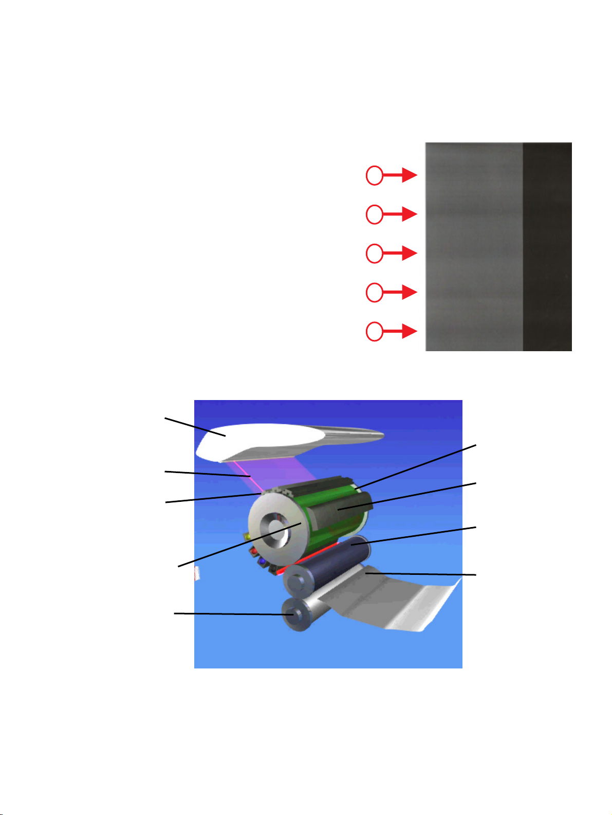
Writing head
Leading edge
5 visible bands
1
2
3
4
5
Figure 1 Banding across page width
Laser beams
Left scorotron
PIP drum sholder
Impression drum
PIP drum gear teeth
Cleaning station
ITM drum
Paper entering the
paper path
Figure 2 Image processing system
EN Introduction 5
Page 8

Troubleshooting Methodology
Perform the following steps:
1. Perform all the steps in the “Pre-troubleshooting checklist” on page 8.
2. “Identifying the banding type” see page 9.
3. Perform all the steps in the relevant troubleshooting topic - “Troubleshooting by banding type” on
page 10.
The banding troubleshooting overview
This is the summary of most of the banding diagnosis steps in this document. There are 3 sections:
Banding Type
Defines banding by its appearance on the print sample job. There are four major types:
Banding type Possible causes
Random banding
Constant banding
Periodic banding
Vibration banding
Electronic, Electrical failures:
• Short circuits
• Faulty or unstable bias contacts
• Static charge breakthrough
• Faulty grounding, etc…
• Local loads
• Faulty consumables
Gear transmission:
• Gear or pully
Most often:
• Constant group banding
• Dynamic mirror / prism
malfunction
• Encoder malfunction
• Main drive / controller
malfunction
• Drum teeth issues
Rotating parts:
• BID unit
• Cleaning station
• Writing head polygon etc.
Can also be:
• Periodic group
• Random group
Troubleshooting Checklists
• These are checklists suspected causes and possible solutions, based on banding type, and are
listed from the most likely to less common.
• Work through the recommended solutions sequentially until the issue is resolved.
• If the issue remains unresolved escalate it to your technical specialist.
Banding Cause (Causes of interference)
Causes are graded from most common to least common.
• Consumables ware and tare.
• Electrical issues.
• Writing head installation and adjustments.
• Screening and LUT calibration artifacts.
• Mechanical pressure, velocity and local loads.
6 EN
Page 9
Banding troubleshooting road map
High-level usage summary:
• Define the banding type and work through the relevant troubleshooting checklist to resolve the issue.
• For details on how to use this table see the “Troubleshooting Methodology” on page 6.
For sample pictures see figures in “Appendix 1 Banding Types - Samples“ on page 15.
ButtonBanding Troubleshooting
Banding
Consistency
Band
grouping
Separations
roubleshooting
Random
banding
E.g. Figure 12
Any
cause
Often:
E
M3
WH2
Constant
In each
Separation
E.g. Figure 9
E
C2
C4
LUT
M1
M2.1
Constant banding
(same position on page)
Constant
Single
Separations
.
E.g. Figure 10
In some
E
C1
LUT
M1
M2.1
Group
E.g. Figure 11
Repeatable
banding
Not shifted
between
Pages
E.g. Figure 13
M1
M3
Periodic banding
(specific frequency on page)
Periodic
Single
Shifted
between
Pages
E.g. Figure 14
LUT
M2.1
M2.2
WH1
C3
Periodic
Group
E.g. Figure 15
Band shifting
between pages
WH2
WH3
M2
M3
Banding
cause
PIP
Blanket
foil
C1
C2
Cause detail
Consumables
C
See page 12
Impression
BID
C3
paper
C4
Electrical
E
See page 12
Focus
WH1
Writing head
WH
See page 13
Dynamic
Mirror/Prism
WH2
Screening / Machine LUT
LUT
See page 13
Other
WH3
Local loads /
Pressure changes
See Appx. 4
M1
Mechanical
See page 14
Gear
Transmission
See Appx. 2 & 3
M2
Teeth
M2.1
M
Vibration
M3
Gear run-out
M2.2
EN 7
Page 10

Banding troubleshooting
Pre-troubleshooting checklist
Before troubleshooting a banding problem, it is imperative that the press is printing properly with all settings
at their nominal or default positions. Banding symptoms will be misleading, amplified or exaggerated if the
press is not set up in this way, not clean or not adjusted properly.
1. Load the banding troubleshooting diagnostic jobs onto the press computer:
• TS_1on_3off horizontal lines.jlt • TS_1on_3off vertical lines.jlt
• TS_Registration 4 pix.jlt • TS_Grey20.jlt
• TS_Banding2_Rev03.jlt
These jobs can be copied from CD or downloaded from the HP Indigo documentation portal:
http://h21021.www2.hp.com/C5/Test%20Jobs/default.aspx
2. Load the recommended paper: 100 - 150 gsm glossy paper, (minimum) size: 320 x 460 long grain.
3. Print a "base point" reference set of prints: TS_Banding2, TS_Gray20, TS_Registration 4 pix.
4. Adjust first transfer.
5. Check that the substrate thickness is defined correctly.
6. Check that the PIP foil age is below 35K impressions and installed correctly.
7. Check that the blanket age is below 25K impressions and installed correctly.
8. Perform a Machine LUT calibration.
9. Check that the impression paper is clean and installed correctly.
10. Check that the PIP break is functioning correctly.
11. Clean all BID units.
12. Check that all press gears are clear of paper, dry ink and other obstructions.
13. Check that all press gears are greased, and oiling points are oiled - daily and monthly routine.
8 Banding troubleshooting EN
Page 11

Identifying the banding type
1. Print 5 copies of the following banding diagnostic jobs:
Print job Diagnostic purpose
TS_Gray20 Defining Banding Consistency
TS_Banding2 Identifying which Separations banding occurs
TS_Registration 4 pix Identify misregistration - banding is accompanied by waves – vertical misregistration
2. Throw away the 1st copy of each job.
3. Inspect copies from 2
1. Arrange the 4 copies of each job side by side on a large surface.
2. Mark major banding on each print sample.
nd
to 5
th
as follows:
Figure 3 TS_Gray20 job Figure 4 TS_Banding2 job
4. If the Banding consistency appears to be Random banding, the cause is probably not mechanical.
Troubleshooting:
Work through the “Random banding - troubleshooting checklist” in the “Banding troubleshooting road
map” on page 7.
5. If the Banding consistency appears to be Repeatable banding (repeated on each page or separation):
Determine if the cause of the banding is mechanical or not:
1. Print 3 copies of the TS_1on_3off horizontal lines job, and the TS_1on_3off vertical lines job.
2. Note: The TS_1on_3off horizontal lines job is extremely sensitive to banding. Ignore any new
bands that may appear. At this stage ONLY focus on the specific banding identified on the
TS_Banding2 job, TS_Gray20 job and customer jobs.
3. Compare the two jobs:
Job comparison Action
Same banding appears at the
same places on both jobs
Horizontal lines job:
•
Has specific banding,
but the vertical lines job:
•
None or much less
Inconclusive
Perform “Troubleshooting Repeatable banding with Nonmechanical causes” on page 10.
•
Perform “Troubleshooting Constant banding with
Mechanical causes” on page 10.
•
Perform “Troubleshooting Periodic banding” on page 11.
Perform “Appendix 7 Optional alternative mechanical banding
diagnostic method” on page 25.
EN Banding troubleshooting 9
Page 12

Troubleshooting by banding type
Troubleshooting Repeatable banding with Non-mechanical causes
• The banding cause is probably not mechanical:
• This is because the TS_1on_3off vertical lines job is not sensitive to mechanical banding.
• But sometimes the cause could still be mechanical, caused by pressure variations. For example
BID pressure, 1
• The same banding appears at the same places on both jobs:
st
or 2nd pressure.
Figure 5 TS_1on_3off horizontal lines Figure 6 TS_1on_3off vertical lines
Troubleshooting:
Work through the “Troubleshooting checklists” in the “Banding troubleshooting road map”
on page 7, for the following banding causes: Electrical, Consumables or LUT.
Troubleshooting Constant banding with Mechanical causes
• The TS_1on_3off horizontal lines job has your specific banding, but the TS_1on_3off vertical
lines job does not at all or has much less:
Figure 7 TS_1on_3off horizontal lines Figure 8 TS_1on_3off vertical lines
(has banding) (has no banding)
The banding cause is probably mechanical
(due to velocity changes or image writing placement problem or image transfer).
Troubleshooting:
1. Measure the distance from the leading edge of the sheet to the banding.
2. Check if the banding is in the “Appendix 4 Constant banding table” on page 21:
• If the banding is in the table, perform the relevant “Diagnostic tips” on page 21.
• If not, the cause is probably defective or dirty gear teeth – see “Appendix 5
Troubleshooting constant banding caused by gear teeth” on page 22.
10 Banding troubleshooting EN
Page 13

N
Troubleshooting Periodic banding
Troubleshooting:
1. Classify the Band grouping: (Single or Group).
2. Mark as many continuous bands as you can on the print sample.
3. Measure banding periods in millimeters (mm).
4. Calculate the banding frequency (in mm or Hz) - see calculation below.
5. Determine if the cause of the banding is mechanical or not:
• Print 3 copies of the TS_1on_3off horizontal lines job, and the TS_1on_3off vertical lines job.
• Note: The TS_1on_3off horizontal lines job is extremely sensitive to banding. Ignore any new
bands that may appear. At this stage ONLY focus on the specific banding identified on the
TS_Banding2 job, TS_Gray20 job and customer jobs.
• Compare the two jobs:
Job comparison Action
Same banding appears at
the same frequency on both
jobs
Horizontal lines job:
•
Has specific banding,
but the vertical lines job:
•
None or much less
Inconclusive
Periodic banding frequency calculation
Notes:
• Marking the bands:
• In general, mark the bottom edge of bands (or group of bands).
• Sometimes there is no clear edge. Mark the center of the bands (or group of bands).
• Measuring the distance between bands (or group of bands).
• Keep consistent - bottom edge to bottom edge, or center to center.
Steps:
1. Measure the distance between 1
2. Count the number of bands (or group of bands)
on the page.
3. Apply the formulas as follows:
Where:
F (mm) = Frequency in mm
F (Hz) = Frequency in Hertz
X = Distance between 1
N = Number of bands (or groups) marked
mmF
)(
HzF =
and measured on the page
=
X
1218
mmF
Determine the cause of the banding as follows:
Locate the banding frequency (that you calculated above) in
“Appendix 3 Periodic banding table – caused by gears and
rotating parts” on page 19.
•
If table shows that the cause is a gear then:
Identify the gear using the “Appendix 2 Gear Transmission
Schemas” on page 18.
•
If the table shows that the cause is not a gear then:
Investigate the relevant component for possible defect or
malfunction.
Perform “Appendix 7 Optional alternative mechanical banding
diagnostic method” on page 25.
st
and last band.
1)(−
)(
st
and last band
X
EN Banding troubleshooting 11
Page 14

Causes of Banding
(C) Consumables banding
There are four major causes:
Press component Possible Causes Appearance / Banding type
Burns, stains, short circuits,
(C1) PIP foil
(C2) Blanket
(C3) BID unit
(C4) Impression paper
mechanical damage and poor
installation.
Mechanical damage after
PSTB jams, stains, electrical /
bias contact issues and poor
installation.
Developer roller stains, voltage
instability.
Impression paper folded. May appear like a single constant banding.
Usually appears like constant banding in some
alternate separations (1
Usually appears like constant banding in each
separation.
Usually appears like periodic banding shifted
between pages.
st
& 3rd or 2nd & 4th).
General solutions for Consumables banding
1. Clean the BID unit.
2. Check that the PIP foil, blanket and impression paper are correctly installed.
3. Replace consumables if necessary.
(E) Electrical banding
Press
component
ITM bias
Scorotrons
BID
ITM bias instability during 1st transfer or short circuits on the PIP foil.
Interferes with the density of dots and / or solid areas.
Low charge creates random background areas around dots.
BID unit voltage instability.
Possible Causes
General solutions for electrical banding
1. Look for faulty bias contacts.
2. Check that the PIP drum is grounded correctly.
3. Check for a faulty BID unit or BID power supply board.
4. Look for short circuits e.g. Blanket on ITM drum has raised areas that touch the anti-dripping tray.
12 Causes of Banding EN
Appearance / Banding
type
Dark and / or light lines
that repeat down the
sheet. Usually appears as
random banding with
sharp edges.
Page 15

(WH) Writing head banding
Press component Possible Causes Appearance / Banding type
(WH1)
Focus adjustment
(WH3)
(WH2)
Dynamic mirror
(WH3) Writing head
press interfaces
Faulty focus adjustment
•
Focus adjustment.
•
Image scaling adjustment.
•
De-skew calibration.
Dynamic mirror malfunction (or
dynamic prism in the HP Indigo
press 3050).
Faulty Writing head installation
on press interfaces.
General solutions for banding caused by the writing head
1. Adjust the writing head focus and leveling.
2. Verify that the writing head parameter files correspond to the writing head serial number.
Reinstall the writing head parameters.
3. Physically unlock the dynamic mirror according to the instruction sticker on the writing head.
4. Adjust image scaling.
5. Check the de-skew calibration.
6. Check the writing head mechanical installation.
7. Check the press installation - press wheels should not touch the floor.
Usually produces 2.25 mm period banding.
0.375 mm period banding.
This can cause any type of banding.
Usually accompanied by random misregistration
issues.
Usually vibration banding 0.7—2.5 mm - constant
groups or periodic groups. (Especially on the HP
Indigo press 3050.)
(LUT) Screening and machine LUT artifact banding
• Screening banding is caused by intrinsic screening artifacts, for example:
• 3.8 mm period banding on Sequin screening.
• Machine LUT banding is caused by faulty machine LUT generation.
Images most affected are screen tints that change from say 5% to 100% in a gradual way:
• Vignettes are light to dark or dark to light areas of a single color.
• Blends are composed of process colors (C, M, Y, and K) that change from one specific color to
another.
• Vignettes and blends may also exhibit some banding if they contain too many steps or if the
machine LUT is not correct.
• For example if the machine LUT was set to the following numbers:
• Step 20 is 20, step 30 is 32, step 40 is 38 and step 50 is 50. (Note that these numbers
are within normal tolerance.)
• If a vignette falls within this range, a band will be created between 30% and 40%.
• The LUT in this example, actually compresses the vignette and generates banding.
General solutions for screening and machine LUT artifact banding
1. Run the Machine LUT generation wizard.
2. Try to print with a different job screen definition for a diagnostic.
3. Replace - blanket. (Run the Machine LUT generation wizard, print again).
4. Replace - PIP (Run the Machine LUT generation wizard, print again).
5. Check the Ink density and conductivity calibration.
Run the Machine LUT generation wizard again.
EN Causes of Banding 13
Page 16

(M) Mechanical interferences
There are two major mechanical interferences: local loads and gear transmission issues:
(M1) Local load
Local loads in the press reduce the velocity of, or cause pressure changes in, the set of image
processing drums, for a moment. This interferes with dot placement at sensitive stages of image
production and transfer:
• Image writing phase - Writing head to PIP drum.
• Image transfer phase - 1
- 2
Local loads occur at:
• Each separation - Example - at the start of 2
• Some separations - Example - during paper input or output.
General solutions for banding caused by local loads – check for:
1. Correct press adjustments - For example 2nd pressure, gripper shaft magnets.
2. Damaged or loose parts in paper path - Gripper shaft assembly, stop station assembly.
3. ITM drum radial freedom - This may produce banding under 2
such cases local loads affect both pressure between drums and drum rotation speed.
4. Parts that vibrate under specific loads that may interfere with the writing head.
- For example on the HP Indigo press 3050 - stop finger noise during paper feed.
(M2) Gear transmission issues interfering with dot placement
Gear transmission issues in the drums and gears, during image writing and transfer, interferes with
dot placement. Banding patterns are created in relation to gear diameter and distance between teeth.
Gear transmission issues are cause by:
Gear transmission issue Possible symptom Possible cause
Periodic banding down
Gear meshing
(M2.1) Defective gear teeth
(M2.2) Gear run out (gear not
centered on its shaft)
the page with tooth to
tooth at a constant
frequency.
Periodic single banding
Periodic groups of
banding
Solutions for gear transmission issues:
1. Clean gears.
2. Grease gears.
3. For Direct Drive presses (HP Indigo press 3500, HP Indigo press 5000, HP Indigo press 5500):
3.1. For banding frequencies: 101.5 mm (12Hz), 50.8 mm (24Hz) and 25.4 mm (48Hz) - This
is related to the main motor, small drive gear (gear 14) and the flywheel - Run the
Harmonic and Torque compensation wizard.
3.2. If the wizard did not correct the issues then - Replace defective gears, main motor or
flywheel where necessary.
4. For non-Direct Drive press (HP Indigo press 3050) -
4.1. Replace defective gears, shafts and bearings where necessary.
There are two other mechanical interferences: pressure and vibration issues:
Pressure issues interfering with dot size
Pressure variations may interfere with dot size and also causes dot smearing.
(M3) Vibration of certain parts
Vibration of certain parts interferes with dot placement or causes dot smearing.
• E.g. 1 - BID unit vibration, 1 separation job can produce groups of 6.8 - 7.0 mm periodic banding.
• E.g. 2 - Writing head vibration usually caused by press operation or local loads. 0.7 - 2.5 mm
frequency range - constant groups or periodic groups - especially for HP Indigo press 3050.
st
transfer - PIP drum to ITM drum.
nd
transfer - ITM drum to impression drum.
nd
transfer pressure.
nd
transfer start or end loads. In
•
Incorrect gear / drum assembly
•
Defective gear (factory error - out of spec)
•
New gear not meshing smoothly with worn gear
•
Defective tooth
•
Incorrect gear assembly
•
Defective bearing (that supports the gear shaft)
14 Causes of Banding EN
Page 17

Appendix 1 Banding Types - Samples
Constant - Single banding
Figure 9 Each separation
Figure 10 Some separations
EN Appendix 1 Banding Types - Samples 15
Page 18

Constant - Group banding
Random banding
Figure 11 Constant group
Figure 12 Random banding
16 Appendix 1 Banding Types - Samples EN
Page 19

Periodic banding
Periodic - Single banding
Figure 13 Not shifted between pages Figure 14 Shifted between pages
Periodic - Group banding
Figure 15 Periodic - Group banding Figure 16 Periodic banding
EN Appendix 1 Banding Types - Samples 17
Page 20

Appendix 2 Gear Transmission Schemas
These schemas are used to locate a gear, when you know the number of teeth in the gear.
How to use these schemas:
1. Identity the gear using the “Appendix 3 Periodic banding table – caused by gears and rotating
parts” on page 19, and get the number of teeth.
2. Locate the gear on the relevant Gear Transmission Schema for your press (see below).
18 Appendix 2 Gear Transmission Schemas EN
Page 21

Appendix 3 Periodic banding table – caused
by gears and rotating parts
This table is used to identity a gear or pulley / other component, when you know the frequency of the banding
or misregistration. How to use this table:
1. Measure the frequency of the banding or misregistration using the “Periodic banding frequency
calculation” on page 11.
2. Identity the gear or pulley / other component in the table below.
• If table shows that the cause is a gear or pulley then:
Identify the gear using the “Appendix 2 Gear Transmission Schemas” on page 18.
• If the table shows that the cause is another component (shown in grey) then:
Investigate the relevant component for possible defect or malfunction.
Vmachine (process) = 1218 [mm/sec]
Gear/Pulley
Banding
Frequency
[mm]
1624.0 0.75 Rotor B pulley 48 Paper feed 3050
Gear/Pulley
Banding
Frequency
[Hz]
Gear or Pulley /
Other component
No. of
teeth
Gear type /
Sub-assembly
Press type
1107.3 1.1 Gear PIP 148 Drive 5000/3050
1072.2 1.136 Rotor A pulley 32 Paper feed 3050
1072.2 1.136 Rotor A pulley 114 Paper feed 3050
529.6 2.3 Helical Gear ITM 74 Drive 5000/3050
529.6 2.3 Gear Impression 114 Drive 5000/3050
529.6 2.3 ITM Spur Gear 114 Drive 5000/3050
133.5 9.07 Developer pulley 34 BID 3050/5000
131 9.3 Developer roller 60 BID 3050/5000
112.8 11 Impression brake gear 24 Paper feed 5000
103.6 11.8 Hand wheel gear 22 Drive 3050/5000
101.5 12 Gear Plastic "frog" 108 Drive 3050
101.5 12 Small drive Gear 14 Drive 3050/5000
99.8 12.2 Timing pulley 24 Cleaning 3050/5000
93.1 13 Impression brake gear 19 Paper feed 5000
89.6 13.6 Gear Imp/Paper feed 19 Paper feed 3050
75.2 16.2 BID motor pulley 19 BID 3050/5000
67.3 18.1 Sponge pulley 17 BID 3050/5000
66.6 18.3 Timing pulley 16 Cleaning 3050/5000
56.4 21.6 Flywheel pulley 44 Drive 3050
56.4 21.6 Flywheel gear 60 Drive 3050
52.4 23.3 Squeegee roller 24 BID 3050/5000
EN Appendix 3 Periodic banding table – caused by gears and rotating parts 19
Page 22

Gear/Pulley
Banding
Frequency
[mm]
Gear/Pulley
Banding
Frequency
[Hz]
Gear or Pulley /
Other component
No. of
teeth
Gear type /
Sub-assembly
Press type
50.8 24 Main motor 14 Drive 5000
34 36 Main motor + controller 14 Drive 5000
33.5 36.4 Rotor A pulley 32 Paper feed 3050
32.7 37.2 Cleaner roller 15 BID 3050/5000
31.5 38.5 Helical Gear ITM 74 Drive 5000
25.4 48 Main motor + controller 14 Drive 5000
9.4 130 Paper feed pulley 31 Paper feed 3050
9.4 130 Rotor A pulley 114 Paper feed 3050
7.3 167.8 Small drive Gear 14 Drive 3050/5000
7.3 167.8 Helical ITM Gear 74 Drive 3050/5000
7.3 167.8 PIP Gear 148 Drive 3050/5000
6.8 179.4 BID unit vibration - BID 3050/5000
4.7 260 Impression Gear 114 Drive 3050/5000
4.7 260 Gear Imp/Paper feed 19 Paper feed 3050
4.7 260 Gear Imp/Paper feed 24 Paper feed 3050
4.7 260 Gear Imp/Paper feed 62 Paper feed 3050
4.7 260 Impression brake gear 24 Paper feed 5000
4.7 260 Impression brake gear 19 Paper feed 5000
4.2 292 Timing pulley 24 Cleaning 3050/5000
4.2 292 Timing pulley 16 Cleaning 3050/5000
3.8 325 De-skew (in Sequin) - S/W screening 3050/5000
3.4 358 Black screen artifact (in HDI-180 lpi) - S/W screening 5000
2.25 542 Polygon - W. Head 3050/5000
2.2 544.2 Developer Gear 40 BID 3050/5000
2.18 558.3 Rear gear mesh - BID 3050/5000
1.8 to 2.5 487-676 General Resonance - W. Head 3050/5000
1.3 949.3 Main Motor Pulley 20 Drive 3050
1.3 949.3 Flywheel pulley 44 Drive 3050
1.15 1,094 Polygon - W. Head 3050/5000
1.0 1,220 Dynamic Prism - W. Head 3050
0.9 1,294.50 Flywheel gear 60 Drive 3050
0.9 1,294.50 Gear Plastic "frog" 108 Drive 3050
0.8 1,627 Polygon - W. Head 3050/5000
0.375 3,253 Scan frequency - W. Head 3050/5000
20 Appendix 3 Periodic banding table – caused by gears and rotating parts EN
Page 23

Appendix 4 Constant banding table
Diagnostic table for constant banding caused by local loads and other causes.
Distance from LE Local loads
mm deg
31-39 65-70
46 75
71-106 95-110
143-155 140-148
173-180 160-165
262 & 350
Couple
220 & 278
Couple
300 245
350 278
350±5 278±5
Gripper
shaft
action
Press
action
Opening Sheet exit 1
st
1
transfer
start
Opening Sheet exit 2
Opening Simplex 1
Opening Simplex 2
nd
2
transfer
start, end
Closing Simplex 1
nd
2
transfer
start
nd
2
transfer
start
Sepr.
num
st
1st transfer
Each
nd
st
1st transfer
nd
Each 1
st
Each 1
Each 1
Occurs Diagnostic tips
Image
writing
Image
writing
Image
writing
st
transfer
st
1
transfer
st
transfer
st
transfer
Print a single proof for diagnostic.
Related to stop stations, gripper shaft,
and magnets adjustment. (SS2 on).
Related to 1st pressure incorrect
adjustment. (too high)
Print a single proof for diagnostic.
Related to stop stations, gripper shaft,
and magnets adjustment. (SS2 on).
Related to stop stations, gripper shaft,
and magnets adjustment. (SS1 on).
Related to stop stations, gripper shaft,
and magnets adjustment. (SS1 on).
Sometimes accompanied by bad
transfer between the banding.
Related to:
st
pressure incorrect adjustment (too
-1
low):
- ITM bearings
- ITM radial freedom
Related to stop stations, gripper shaft,
and magnets adjustment. (SS1 on).
Related to substrate definition and 2
nd
pressure adjustment. Use “Appendix
6 Second transfer banding troubleshooting procedure” on page
24 for troubleshooting.
Electrical banding,
Gripper clamp touches the blanket.
Related to banded gripper clamps,
incorrect gripper shaft adjustments,
and bubbles on blanket.
350-455
Group
355 282
397 310
278-350
Group
Exit roller
"jumps"
Closing Simplex 2
nd
2
transfer
start
Each
nd
Each
Image
writing
Image
writing
Image
writing
Print with no exit roller for diagnostic.
Replace springs.
Related to stop stations, gripper shaft,
and magnets adjustment. (SS1 on).
Related to substrate definition and 2
pressure adjustment. Use “Appendix
6 Second transfer banding troubleshooting procedure” on page
24 for troubleshooting.
EN Appendix 4 Constant banding table 21
nd
Page 24

Appendix 5 Troubleshooting constant
banding caused by gear teeth
• A defective or dirty tooth on one of main gears causes constant banding.
• You will probably not find them it in the Constant banding table.
• Constant banding - Some separations
A defective tooth on the PIP gear usually causes banding on the some separations. This is because
alternate separations are produced on the same side of the PIP drum (MK on one side of the PIP and YC
on the other side).
• Constant banding - Each separation
A defective tooth on the ITM gears or impression drum usually causes banding that appears on each
separation.
Locating a defective or dirty tooth on the ITM drum gear or
impression drum gear
Banding due to a defective or dirty tooth on ITM drum appears on each separation.
1. Mark the banding on your print sample.
2. Press the Inching button and insert the printed page into the grippers.
3. Using the hand wheel, manually rotate the press, and keep your eye on your band.
4. Stop rotating one or two centimeters before your band reaches the ITM drum.
5. Mark the gear tooth (e.g. with a small sticker or with tip-ex) in line with your band. See Figure 17.
6. The defective or dirty tooth will be in a range of 3 to 5 teeth on either side of your mark.
7. Clean and inspect this area.
The banding
Location of problematic tooth
Figure 17 Marking the defective or dirty tooth on the ITM drum
Locate the defective or dirty tooth on the PIP drum gear
Banding appears on some separations: alternate separations (1st & 3rd or 2nd & 4th).
The defective or dirty tooth may be on either half of the PIP drum. Null cycles can occur at any point in
between separations. This makes it difficult to determine which PIP half has the defective tooth. Therefore
we will troubleshoot both halves of the PIP drum at the same time.
22 Appendix 5 Troubleshooting constant banding caused by gear teeth EN
Page 25

Steps
1. Use one of the banding diagnostic jobs. Mark the banding on your print sample.
2. Read the position of the banding on the printed scale from the leading edge of page, in degrees.
3. For example: you have banding at 240 deg.
4. Manually set the machine angle position to: Encoder Half “0”, Current Position “240” see Figure 18:
Figure 18 Troubleshooting both halves of the PIP drum
Shaft with leveling
ring (this is
approximately in
line with the laser
beams).
Mark a point
on the PIP
drum shoulder
Empty location
of the left
scorotron
PIP drum
shoulder
Figure 19 Marking the location on the gear tooth on the PIP drum shoulder
5. Take out the left scorotron unit.
6. Mark the PIP drum shoulder with a sticker or marker directly below the shaft with the leveling ring.
See Figure 19.
7. Manually set the machine angle position to: Encoder Half “1” and the same Current Position “240”.
See Figure 18.
8. Mark the drum shoulder for the other drum half using the same process.
9. These marks are on the front side of the PIP drum. The dirty or damaged tooth is in line with one of
these points.
10. Manually rotate the press until one of the marks is visible from the paper input side.
11. Mark the tooth that is in line with the mark on the PIP shoulder.
12. Manually rotate the press until the second mark is visible from the paper input side.
13. Mark the tooth that is in line with the mark on the PIP shoulder.
14. The defective or dirty tooth will be in a range of 3 to 5 teeth on either side of your mark.
15. Clean and inspect these areas on both halves of the PIP drum.
EN Appendix 5 Troubleshooting constant banding caused by gear teeth 23
Page 26

Appendix 6 Second transfer banding troubleshooting procedure
2nd transfer banding is visible at 278 degrees and 310 degrees. 278 degree banding is a technology issue and
exists on ALL normally calibrated presses. The procedure below reduces this banding to an acceptable level.
Note: Reprint the banding diagnostic job (TS_Banding2 job or TS_Gray20 job) and reevaluate
the banding level for each cycle of troubleshooting in the following procedure.
• After each troubleshooting cycle, keep print samples for your reference.
• Follow the defined troubleshooting step order.
• Contact your technical specialist to make a decision about part replacement.
• Remember, after each part replacement, reprint and reconsider banding levels from the beginning.
Steps
• Prior to troubleshooting, clean, oil and grease the press.
• Perform the procedure described in the “Pre-troubleshooting checklist” on page 8.
1. Check:
1.1. Substrate thickness and glossiness definition.
1.2. Impression paper thickness definition and correct installation.
1.3. Blanket correct installation - especially not overlapping the ITM drum shoulder.
1.4. Reset 2
2. Perform:
2.1. First transfer calibration.
2.2. Machine LUT generation or at least color adjustment.
3. Replace:
3.1. Blanket. (Note: A new blanket will have a high level of 2nd transfer banding. Before printing
the banding diagnostic, print 200-500 impressions to get realistic banding level.)
3.2. PIP foil.
3.3. Impression paper.
4. Check:
4.1. PIP brake correct operation.
4.2. Impression drum brake correct operation.
4.3. All press fans are working correctly.
4.4. All ventilation hoses are firmly connected to the correct places - especially the ITM feed fan.
4.5. Print with no exit roller for diagnostic.
4.6. Run at least 3000 impressions to stabilize IR sensor body temperature.
4.7. Run the ITM IR sensor adjustment wizard.
4.8. Run the Impression drum IR sensor calibration wizard.
Note:
• Temperature changes of more than 5 deg Celsius required 2
• Make sure that your external thermometer is perfectly calibrated.
5. Adjust:
5.1. Run the Impression engage calibration wizard.
5.2. 2
5.2.1. On the Substrate screen, when adjusting the gap, set the Current Position between 310 –
315 deg. (This is the position at which the 2
5.3. Adjust the 2
5.3.1. Run the press. Perform fine tuning according to the Balancing the second transfer pressure
with SPV document (CA293-04790).
Note: For HP Indigo press 5000 with HP Indigo press software version 7.4.3 and higher - The
SPV software tool can be used for adjusting 2
nd
pressure correction in the Blanket MMI screen, or in the Paper Definition.
nd
transfer gap (5000, 3000).
nd
transfer pressure. Run the wizard (5500).
nd
transfer gap readjustment.
nd
transfer begins.)
nd
transfer pressure tuning.
24 Appendix 6 Second transfer banding - troubleshooting procedure EN
Page 27

Appendix 7 Optional alternative mechanical
banding diagnostic method
If a "TS_1on_3off vertical line transparent diagnostic foil" is available, you can check if banding is
mechanical by doing the following:
Note:
You can create this foil for yourself by running the TS_1on_3off vertical line transparent diagnostic
foil job on transparent substrate. You can download the job from the HP Indigo documentation
portal: http://h21021.www2.hp.com/C5/Test%20Jobs/default.aspx
1. Print a TS_1on_3off horizontal lines job.
2. Put the transparency on the TS_1on_3off horizontal lines job. See Figure 20.
3. Rotate the transparency and look for a “wave" appearance at the location of the banding.
4. If there is a “wave”/s appearance, define its period and position – this is a mechanical issue or a
writing head writing issue.
5. If no “wave”/s appear, look for an Electrical, Consumables, Pressure variation or software cause
of the problem.
Extreme interruption
of smooth "Moire
waves” indicates
mechanical cause of
the banding. See the
“Banding
troubleshooting
road map” on page
7 for troubleshooting.
Figure 20 Detecting interruptions in the "Moire waves”
EN Appendix 7 Optional alternative mechanical banding diagnostic method 25
Page 28

Notes
Page
number
Remarks
26 Notes EN
Page 29

Page 30

Copyright © 2008 Hewlett-Packard Company
This is an HP Indigo digital print. Printed in Israel.
www.hp.com/go/indigo
reorder: P/N CA293-04200
 Loading...