

Page 1

Maintenance and Service Guide
HP EliteDesk 705 G1 Microtower
HP EliteDesk 705 G1 Small Form Factor
HP EliteDesk 705 G1 Desktop Mini
Page 2

© Copyright 2014 Hewlett-Packard
Development Company, L.P. The information
contained herein is subject to change without
notice.
Intel and Pentium are trademarks of Intel
Corporation in the U.S. and other countries.
Bluetooth is a trademark owned by its
proprietor and used by Hewlett-Packard
Company under license. Microsoft, Windows,
WIndows 7, and Windows 8.1 are U.S.
registered trademarks of the Microsoft group
of companies. SD Logo is a trademark of its
proprietor.
The only warranties for HP products and
services are set forth in the express warranty
statements accompanying such products and
services. Nothing herein should be construed
as constituting an additional warranty. HP shall
not be liable for technical or editorial errors or
omissions contained herein.
This document contains proprietary
information that is protected by copyright. No
part of this document may be photocopied,
reproduced, or translated to another language
without the prior written consent of HewlettPackard Company.
Product notice
This guide describes features that are common
to most models. Some features may not be
available on your computer.
Not all features are available on all editions of
Windows 8.1. This computer may require
upgraded and/or separately purchased
hardware, drivers, and/or software to take full
advantage of Windows 8.1 functionality. See
http://www.microsoft.com for details.
This computer may require upgraded and/ or
separately purchased hardware and/or a DVD
drive to install the Windows 7 software and
take full advantage of Windows 7 functionality.
See http://windows.microsoft.com/en-us/
windows7/get-know-windows-7 for details.
Second Edition (November 2014)
First Edition (August 2014)
Document Part Number: 762914-002
Page 3

Safety warning notice
WARNING! To reduce the possibility of heat-related injuries or of overheating the device, do not place
the device directly on your lap or obstruct the device air vents. Use the device only on a hard, flat surface. Do
not allow another hard surface, such as an adjoining optional printer, or a soft surface, such as pillows or
rugs or clothing, to block airflow. Also, do not allow the AC adapter to contact the skin or a soft surface, such
as pillows or rugs or clothing, during operation. The device and the AC adapter comply with the useraccessible surface temperature limits defined by the International Standard for Safety of Information
Technology Equipment (IEC 60950).
iii
Page 4

iv Safety warning notice
Page 5

Table of contents
1 Product Features ........................................................................................................................................... 1
Standard Configuration Features .......................................................................................................................... 1
Microtower ........................................................................................................................................... 1
Small form factor ................................................................................................................................ 1
Desktop mini ........................................................................................................................................ 2
Front panel components, microtower .................................................................................................................. 3
Front panel components, small form factor ......................................................................................................... 4
Front panel components, desktop mini ................................................................................................................ 5
Rear panel components, microtower .................................................................................................................... 6
Rear panel components, small form factor .......................................................................................................... 7
Rear panel components, desktop mini ................................................................................................................. 8
Serial Number Location ......................................................................................................................................... 9
2 Illustrated parts catalog .............................................................................................................................. 10
Microtower (MT) chassis spare parts .................................................................................................................. 10
Computer major components ........................................................................................................... 10
Cables ................................................................................................................................................ 12
Misc parts .......................................................................................................................................... 13
Drives ................................................................................................................................................. 15
Misc boards ........................................................................................................................................ 16
Small Form Factor (SFF) chassis spare parts ...................................................................................................... 17
Computer major components ........................................................................................................... 17
Cables ................................................................................................................................................ 19
Misc parts .......................................................................................................................................... 20
Drives ................................................................................................................................................. 22
Misc boards ........................................................................................................................................ 23
Desktop Mini (DM) chassis spare parts ............................................................................................................... 24
Computer major components ........................................................................................................... 24
Cables ................................................................................................................................................ 25
Misc parts .......................................................................................................................................... 26
Drives ................................................................................................................................................. 27
3 Routine care, SATA drive guidelines, and disassembly preparation .................................................................. 28
Electrostatic discharge information ................................................................................................................... 28
Generating static ............................................................................................................................... 28
Preventing electrostatic damage to equipment .............................................................................. 29
v
Page 6

Personal grounding methods and equipment .................................................................................. 29
Grounding the work area .................................................................................................................. 29
Recommended materials and equipment ........................................................................................ 30
Operating guidelines ........................................................................................................................................... 30
Routine care ......................................................................................................................................................... 31
General cleaning safety precautions ................................................................................................ 31
Cleaning the Computer Case ............................................................................................................. 31
Cleaning the keyboard ...................................................................................................................... 31
Cleaning the monitor ......................................................................................................................... 32
Cleaning the mouse ........................................................................................................................... 32
Service considerations ........................................................................................................................................ 32
Power supply fan ............................................................................................................................... 32
Tools and software Requirements ................................................................................................... 32
Screws ............................................................................................................................................... 33
Cables and connectors ...................................................................................................................... 33
Hard Drives ........................................................................................................................................ 33
Lithium coin cell battery ................................................................................................................... 33
SATA hard drives .................................................................................................................................................. 34
SATA hard drive cables ........................................................................................................................................ 34
SATA data cable ................................................................................................................................. 34
SMART ATA drives ................................................................................................................................................ 34
Cable management .............................................................................................................................................. 35
4 Removal and replacement procedures – Microtower (MT) chassis .................................................................... 36
Preparation for disassembly ............................................................................................................................... 36
Access panel ........................................................................................................................................................ 37
Front bezel ........................................................................................................................................................... 38
Optical drive bezel blank ..................................................................................................................................... 39
Battery ................................................................................................................................................................. 40
Memory ................................................................................................................................................................ 42
DIMMs ................................................................................................................................................ 42
DDR3-SDRAM DIMMs ......................................................................................................................... 42
Populating DIMM sockets .................................................................................................................. 42
Installing DIMMs ................................................................................................................................ 43
Expansion cards ................................................................................................................................................... 45
Drives ................................................................................................................................................................... 49
Drive positions ................................................................................................................................... 51
Removing a slim optical drive ........................................................................................................... 51
Installing a slim optical drive ............................................................................................................ 52
Removing a hard drive ...................................................................................................................... 53
Installing a hard drive ....................................................................................................................... 54
vi
Page 7

Drive power cable ................................................................................................................................................ 58
Front I/O and power switch assembly ................................................................................................................. 59
Heat sink .............................................................................................................................................................. 61
Processor ............................................................................................................................................................. 62
Speaker ................................................................................................................................................................ 63
Rear chassis fan ................................................................................................................................................... 65
Power supply ....................................................................................................................................................... 66
System board ....................................................................................................................................................... 68
System board callouts ...................................................................................................................... 70
5 Removal and replacement procedures – small form factor (SFF) chassis .......................................................... 72
Preparation for disassembly ............................................................................................................................... 72
Access panel ........................................................................................................................................................ 73
Front bezel ........................................................................................................................................................... 73
Front bezel security ............................................................................................................................................. 74
Bezel blanks ......................................................................................................................................................... 75
Battery ................................................................................................................................................................. 76
Memory ................................................................................................................................................................ 78
DIMMs ................................................................................................................................................ 78
DDR3-SDRAM DIMMs ......................................................................................................................... 78
Populating DIMM sockets .................................................................................................................. 78
Installing DIMMs ................................................................................................................................ 79
Expansion card .................................................................................................................................................... 81
Drives ................................................................................................................................................................... 85
Drive positions ................................................................................................................................... 86
Installing and Removing Drives ........................................................................................................ 86
Removing a 3.5-inch device ............................................................................................ 88
Installing a 3.5-inch device ............................................................................................. 89
Removing a slim optical drive ........................................................................................ 92
Installing a slim optical drive .......................................................................................... 93
Removing and replacing a 3.5-inch hard drive .............................................................. 95
Removing a 2.5-inch hard drive ..................................................................................... 98
Installing a 2.5-inch hard drive ....................................................................................... 98
Drive power cable .............................................................................................................................................. 100
Baffle ................................................................................................................................................................. 101
Hood sensor ....................................................................................................................................................... 102
Front I/O assembly ............................................................................................................................................ 103
Power switch ..................................................................................................................................................... 106
Speaker .............................................................................................................................................................. 108
Heat sink ............................................................................................................................................................ 109
Processor ........................................................................................................................................................... 112
vii
Page 8

Power supply ..................................................................................................................................................... 114
System board ..................................................................................................................................................... 116
System board callouts .................................................................................................................... 118
Using the Small Form Factor Computer in a Tower Orientation ...................................................................... 120
6 Removal and replacement procedures – desktop mini (DM) chassis ............................................................... 121
Preparation for disassembly ............................................................................................................................. 121
Access panel ...................................................................................................................................................... 122
Hard drive .......................................................................................................................................................... 123
Speaker .............................................................................................................................................................. 126
Front bezel ......................................................................................................................................................... 128
Memory .............................................................................................................................................................. 129
SODIMMs .......................................................................................................................................... 129
DDR3-SDRAM SODIMMs .................................................................................................................. 129
Populating SODIMM sockets ........................................................................................................... 130
Replacing SODIMMs ......................................................................................................................... 131
Replacing the battery ........................................................................................................................................ 133
Heat sink ............................................................................................................................................................ 136
Processor ........................................................................................................................................................... 137
Fan ..................................................................................................................................................................... 138
Drive cage .......................................................................................................................................................... 139
WLAN module .................................................................................................................................................... 141
M.2 solid-state drive ......................................................................................................................................... 143
External antennas (select models only) ........................................................................................................... 145
System board ..................................................................................................................................................... 148
System board callouts .................................................................................................................... 151
WLAN antennas ................................................................................................................................................. 152
Changing from desktop to tower configuration ............................................................................................... 156
7 Computer Setup (F10) Utility ...................................................................................................................... 157
Computer Setup (F10) Utilities .......................................................................................................................... 157
Using Computer Setup (F10) Utilities ............................................................................................. 158
Computer Setup—File .................................................................................................................... 159
Computer Setup—Storage ............................................................................................................. 160
Computer Setup—Security ............................................................................................................. 161
Computer Setup—Power ................................................................................................................ 164
Computer Setup—Advanced .......................................................................................................... 165
Recovering the Configuration Settings ............................................................................................................. 167
viii
Page 9

8 Troubleshooting without diagnostics .......................................................................................................... 168
Safety and comfort ............................................................................................................................................ 168
Before you call for technical support ................................................................................................................ 168
Helpful hints ...................................................................................................................................................... 169
Solving general problems ................................................................................................................................. 170
Solving power problems ................................................................................................................................... 173
Solving hard drive problems ............................................................................................................................. 175
Solving media card reader problems ................................................................................................................ 177
Solving display problems .................................................................................................................................. 178
Solving audio problems ..................................................................................................................................... 182
Solving printer problems ................................................................................................................................... 184
Solving keyboard and mouse problems ........................................................................................................... 185
Solving Hardware Installation Problems .......................................................................................................... 187
Solving Network Problems ................................................................................................................................ 189
Solving memory problems ................................................................................................................................ 192
Solving CD-ROM and DVD problems ................................................................................................................. 194
Solving USB flash drive problems ..................................................................................................................... 196
Solving front panel component problems ........................................................................................................ 197
Solving Internet access problems ..................................................................................................................... 197
Solving software problems ............................................................................................................................... 198
9 POST error messages ................................................................................................................................. 200
POST numeric codes and text messages .......................................................................................................... 200
Interpreting POST diagnostic front panel LEDs and audible codes .................................................................. 205
10 Password security and resetting CMOS ...................................................................................................... 208
Resetting the password jumper ........................................................................................................................ 208
Changing a Setup or Power-On password ........................................................................................................ 209
Deleting a Setup or Power-On password .......................................................................................................... 210
Clearing and resetting the CMOS ....................................................................................................................... 210
11 HP PC Hardware Diagnostics ..................................................................................................................... 212
Why run HP PC Hardware Diagnostics .............................................................................................................. 212
How to access and run HP PC Hardware Diagnostics ....................................................................................... 212
Downloading HP PC Hardware Diagnostics (UEFI) to a USB device .................................................................. 2 12
12 System backup and recovery .................................................................................................................... 214
Backing up, restoring, and recovering in Windows 8.1 or Windows 8 ............................................................. 214
Creating recovery media and backups ........................................................................................... 214
Restoring and recovering using Windows tools ............................................................................. 214
ix
Page 10

Using Reset when the system is not responding ......................................................... 215
Recovery using the Windows recovery USB flash drive ............................................... 215
Recovery using Windows operating system media (purchased separately) .............. 216
Backing up, restoring, and recovering in Windows 7 ........................................................................................ 216
Creating recovery media ................................................................................................................. 217
Creating recovery media using HP Recovery Manager (select models only) .............. 217
Creating recovery discs with HP Recovery Disc Creator (select models only) ............ 218
Creating recovery discs .............................................................................. 218
Backing up your information ........................................................................................ 219
System Restore ............................................................................................................................... 219
System Recovery ............................................................................................................................. 220
System Recovery when Windows is responding .......................................................... 220
System Recovery when Windows is not responding ................................................... 221
System Recovery using recovery media (select models only) .................................... 221
Using HP Recovery Disc operating system discs (select models only) ....................... 222
Appendix A Power Cord Set Requirements ...................................................................................................... 224
General Requirements ....................................................................................................................................... 224
Japanese Power Cord Requirements ................................................................................................................ 224
Country-Specific Requirements ........................................................................................................................ 225
Appendix B Statement of Volatility ................................................................................................................ 226
Appendix C Specifications ............................................................................................................................. 228
MT Specifications ............................................................................................................................................... 228
SFF Specifications .............................................................................................................................................. 230
DM Specifications .............................................................................................................................................. 231
Index ........................................................................................................................................................... 232
x
Page 11
1 Product Features
Standard Configuration Features
Features may vary depending on the model. For support assistance and to learn more about the hardware
and software installed on your computer model, run the HP Support Assistant utility.
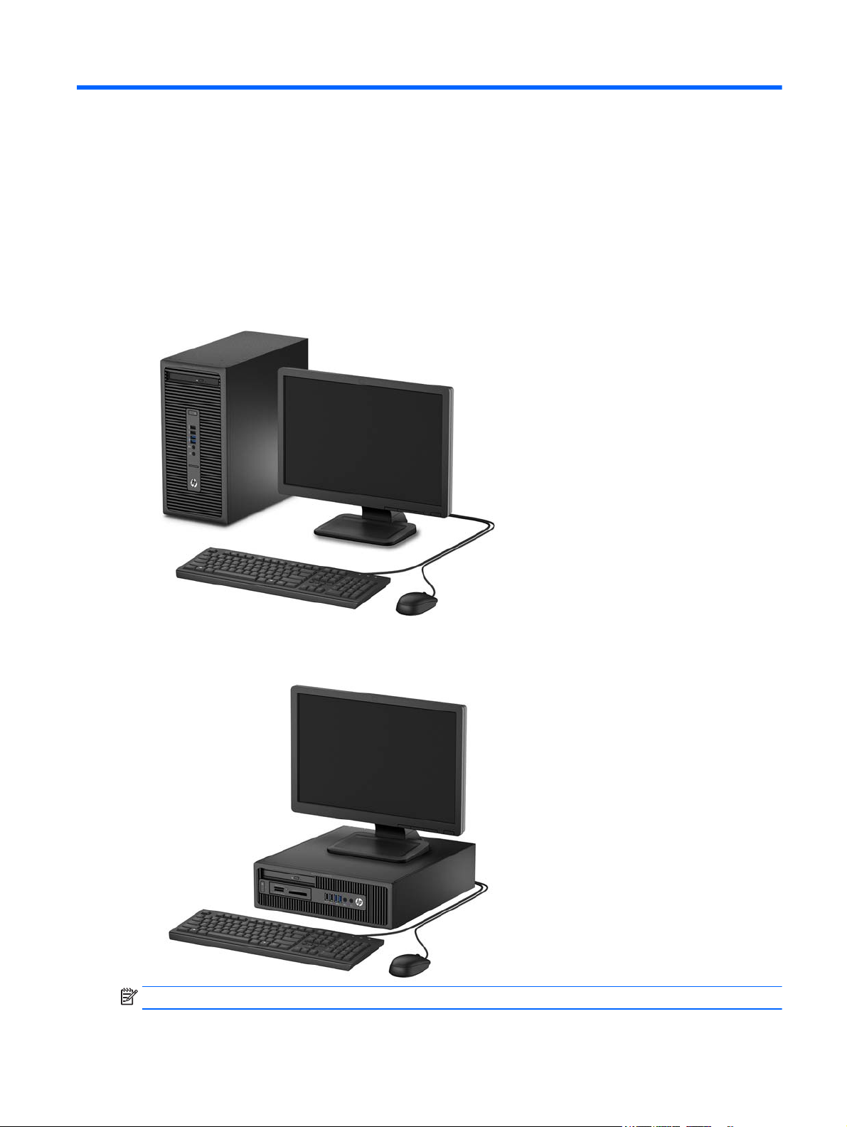
Microtower
Small form factor
NOTE: The small form factor can be used in a tower orientation or a desktop orientation.
Standard Configuration Features 1
Page 12
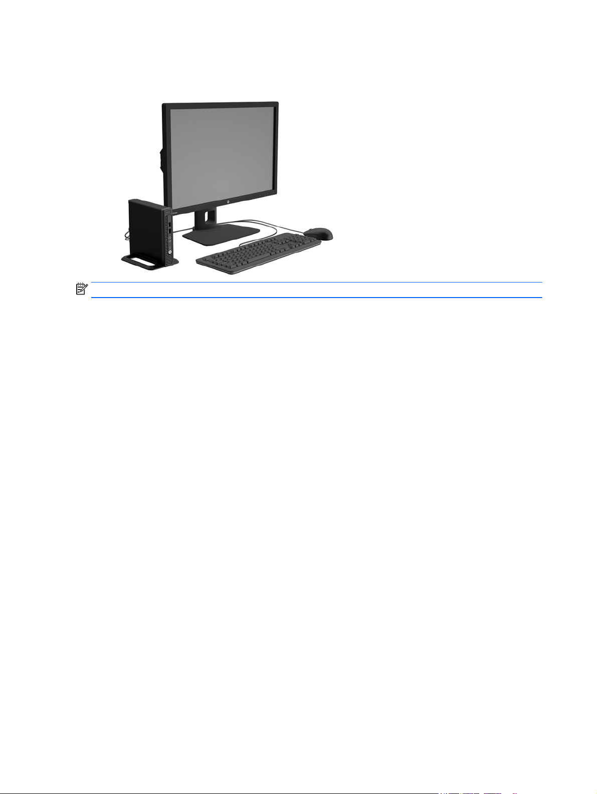
Desktop mini
NOTE: The desktop mini can be used in a tower orientation or a desktop orientation.
2 Chapter 1 Product Features
Page 13
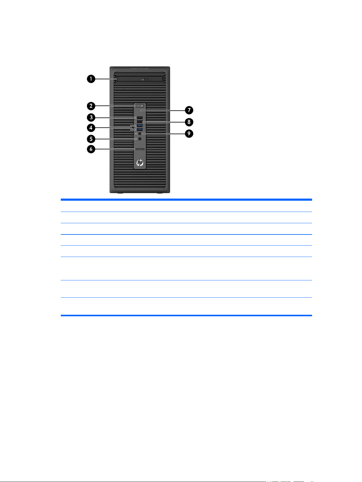
Front panel components, microtower
Drive configuration may vary by model. Some models have a bezel blank covering the optical drive bay.
1 Slim Optical Drive (optional) 6 SD Card Reader
2 Dual-State Power Button 7 Hard Drive Activity Light
3 USB 2.0 Port - Charging (black) 8 USB 2.0 Port (black)
4 USB 3.0 Ports (blue) 9 Microphone/Headphone Connector
5 Headphone Connector
NOTE: When a device is plugged into the Microphone/Headphone Connector, a dialog box will pop up asking if you want
to use the connector for a microphone Line-In device or a headphone. You can reconfigure the connector at any time by
double-clicking the Audio Manager icon in the Windows taskbar.
NOTE: The USB 2.0 Port - Charging also provides current to charge a device such as a Smart Phone. The charging current
is available whenever the power cord is plugged into the system, even when the system is off.
NOTE: The Power On Light is normally white when the power is on. If it is flashing red, there is a problem with the
computer and it is displaying a diagnostic code.
Front panel components, microtower 3
Page 14
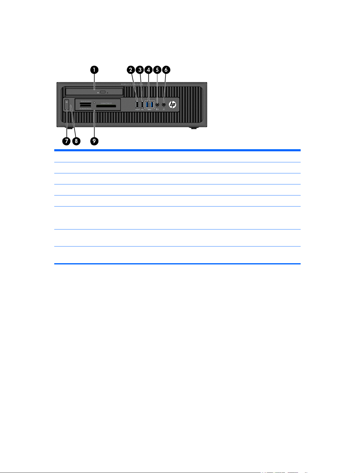
Front panel components, small form factor
Drive configuration may vary by model. Some models have a bezel blank covering one or more drive bays.
1 Slim Optical Drive (optional) 6 Headphone Connector
2 USB 2.0 Port - Charging (black) 7 Dual-State Power Button
3 USB 2.0 Port (black) 8 Hard Drive Activity Light
4 USB 3.0 Ports (blue) 9 3.5-inch Media Card Reader (optional)
5 Microphone/Headphone Connector
NOTE: When a device is plugged into the Microphone/Headphone Connector, a dialog box will pop up asking if you want
to use the connector for a microphone Line-In device or a headphone. You can reconfigure the connector at any time by
double-clicking the Audio Manager icon in the Windows taskbar.
NOTE: The USB 2.0 Port - Charging also provides current to charge a device such as a Smart Phone. The charging current
is available whenever the power cord is plugged into the system, even when the system is off.
NOTE: The Power On Light is normally white when the power is on. If it is flashing red, there is a problem with the
computer and it is displaying a diagnostic code.
4 Chapter 1 Product Features
Page 15
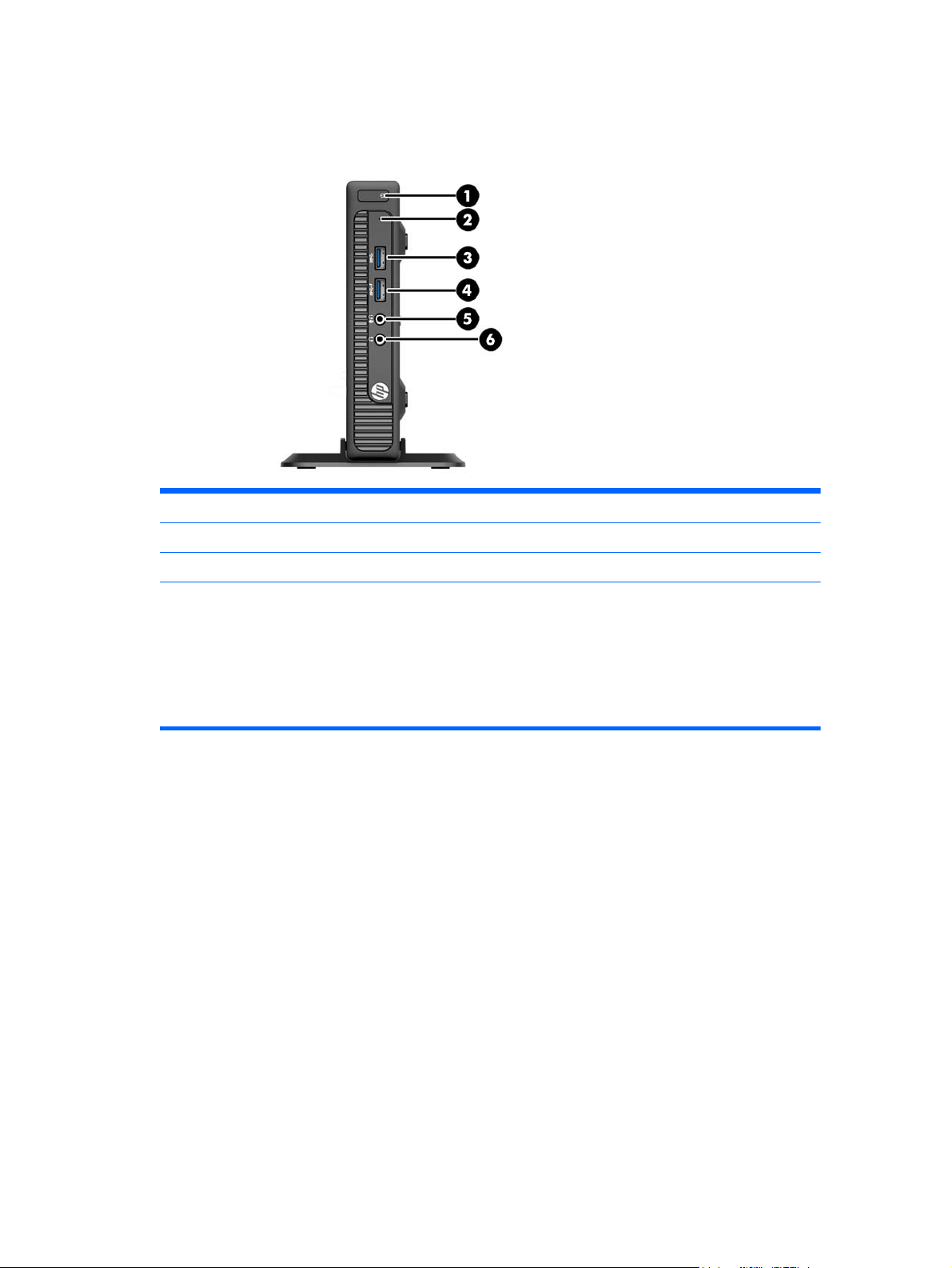
Front panel components, desktop mini
Drive configuration may vary by model. Some models have a bezel blank covering one or more drive bays.
1 Dual-State Power Button 4 USB 3.0 Port - Charging
2 Hard Drive Activity Light 5 Microphone/Headphone Connector
3 USB 3.0 Port 6 Headphone Connector
NOTE: The USB 3.0 Port - Charging also provides current to charge a device such as a Smart Phone. The charging current
is available whenever the power cord is plugged into the system, even when the system is off.
NOTE: When a device is plugged into the Microphone/Headphone Connector, a dialog box will pop up asking if you want
to use the connector for a microphone Line-In device or a headphone. You can reconfigure the connector at any time by
double-clicking the Audio Manager icon in the Windows taskbar.
NOTE: The Power On Light is normally white when the power is on. If it is flashing red, there is a problem with the
computer and it is displaying a diagnostic code. Refer to the Maintenance and Service Guide to interpret the code.
Front panel components, desktop mini 5
Page 16
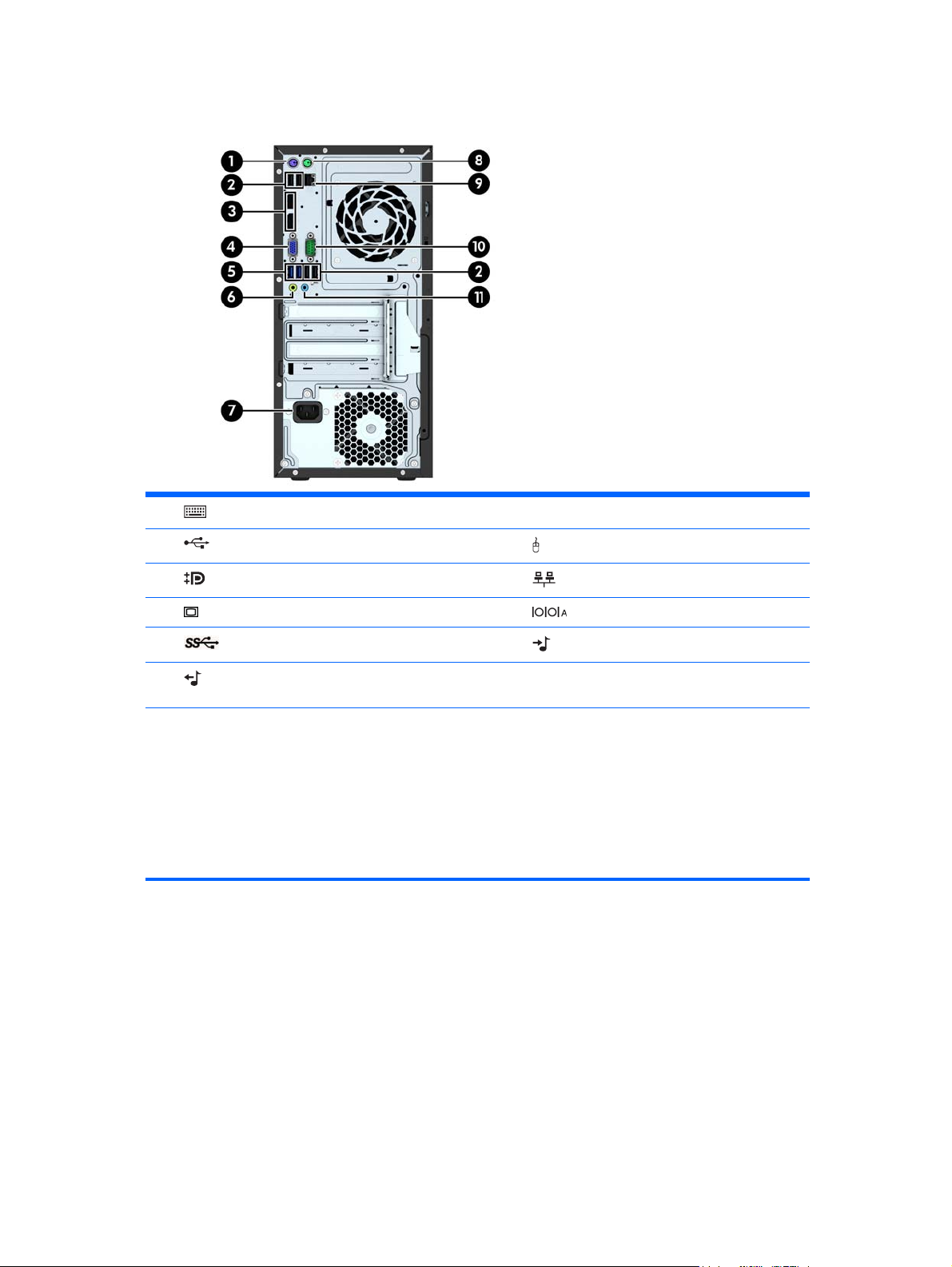
Rear panel components, microtower
1 PS/2 Keyboard Connector (purple) 7 Power Cord Connector
2
3
4
5
6
NOTE: An optional second serial port and an optional parallel port are available from HP.
When a device is plugged into the blue Line-In Audio Connector, a dialog box will pop up asking if you want to use the
connector for a line-in device or a microphone. You can reconfigure the connector at any time by double-clicking the Audio
Manager icon in the Windows taskbar.
When a graphics card is installed in one of the system board slots, the video connectors on the graphics card and/or the
integrated graphics on the system board may be used. The specific graphics card installed and software configuration will
determine the behavior.
The system board graphics can be disabled by changing settings in Computer Setup.
USB 2.0 Ports (black) 8 PS/2 Mouse Connector (green)
DisplayPort Monitor Connectors 9 RJ-45 Network Connector
VGA Monitor Connector 10 Serial Connector
USB 3.0 Ports (blue) 11 Line-In Audio Connector (blue)
Line-Out Connector for powered audio devices
(green)
6 Chapter 1 Product Features
Page 17

Rear panel components, small form factor
1 PS/2 Mouse Connector (green) 7 PS/2 Keyboard Connector (purple)
2
3
4
5
6 Power Cord Connector
NOTE: An optional second serial port and an optional parallel port are available from HP.
When a device is plugged into the blue Line-In Audio Connector, a dialog box will pop up asking if you want to use the
connector for a line-in device or a microphone. You can reconfigure the connector at any time by double-clicking the Audio
Manager icon in the Windows taskbar.
When a graphics card is installed in one of the system board slots, the video connectors on the graphics card and/or the
integrated graphics on the system board may be used. The specific graphics card installed and software configuration will
determine the behavior.
The system board graphics can be disabled by changing settings in Computer Setup.
RJ-45 Network Connector 8 DisplayPort Monitor Connectors
Serial Connector 9 VGA Monitor Connector
USB 2.0 Ports (black) 10 USB 3.0 Ports (blue)
Line-In Audio Connector (blue) 11 Line-Out Connector for powered audio
devices (green)
Rear panel components, small form factor 7
Page 18
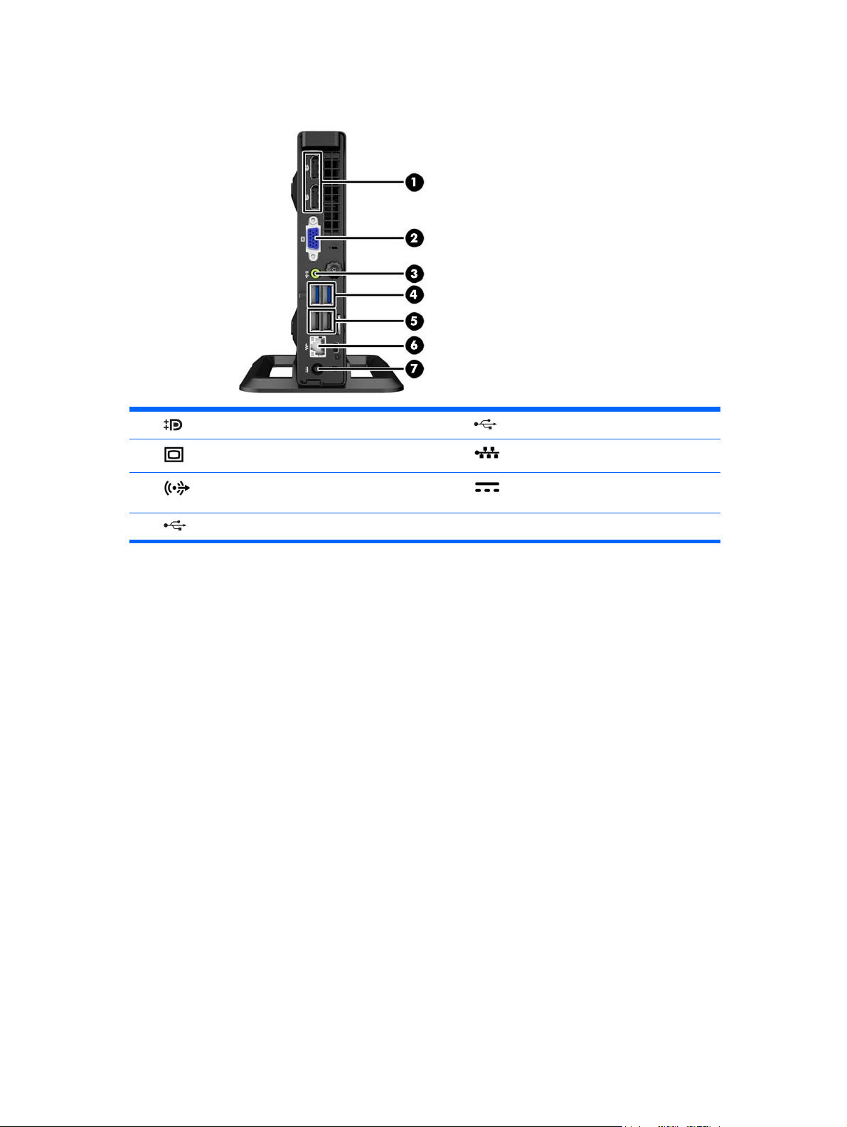
Rear panel components, desktop mini
1 DisplayPort Monitor Connectors 5 USB 2.0 Ports (black)
2
3
4
VGA Monitor Connector 6 RJ-45 Network Connector
Line-Out Connector for powered audio devices
(green)
USB 3.0 Ports (blue)
7 Power Cord Connector
8 Chapter 1 Product Features
Page 19
Serial Number Location
Each computer has a unique serial number and a product ID number that are located on the exterior of the
computer. Keep these numbers available for use when contacting customer service for assistance.
Serial Number Location 9
Page 20
2 Illustrated parts catalog
Microtower (MT) chassis spare parts
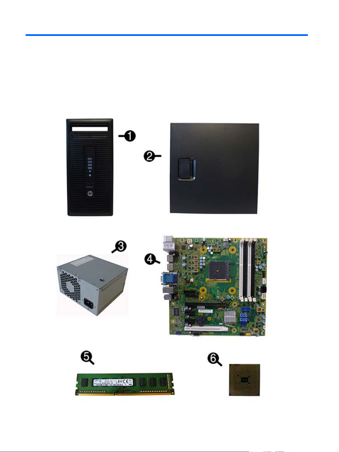
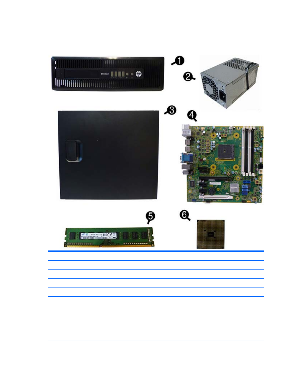
Computer major components
10 Chapter 2 Illustrated parts catalog
Page 21

Item Description
(1) Front bezel
* Slim optical drive bezel blank
(2) Access panel
(3) Power supply
280W, 92% efficient
280W, 90% efficient
280W, 85% efficient (for use only in China)
280W, standard
(4) System board (includes replacement thermal material)
For use in models without Windows 8.1
For use in models with Windows 8.1 Standard
For use in models with Windows 8.1 Professional
For use in NetClone models
(5) Memory modules (PC3-12800, 1600-MHz)
8-GB
4-GB
(6) Processors (include replacement thermal material)
AMD A10-7850B, 3.7 GHz
AMD A10-7800B, 3.57 GHz
AMD A10-6800B, 4.1 GHz
AMD A8-7600B, 3.1 GHz
AMD A8-6500B, 3.5 GHz
AMD A6-7400B, 3.5 GHz
AMD A6-6400B, 3.9 GHz
AMD A4-7350B, 3.9 GHz
AMD A4-6300B, 3.7 GHz
Microtower (MT) chassis spare parts 11
Page 22
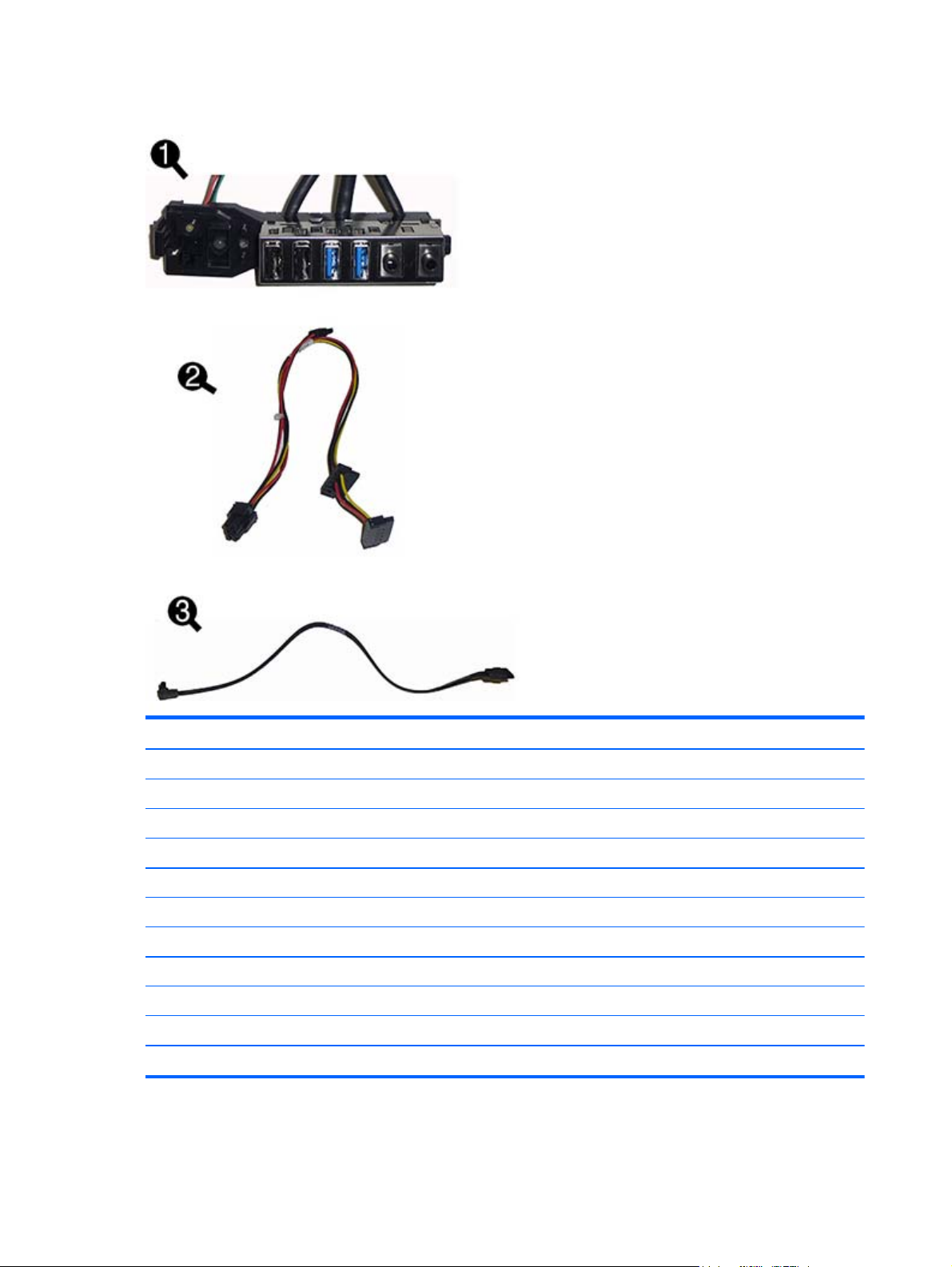
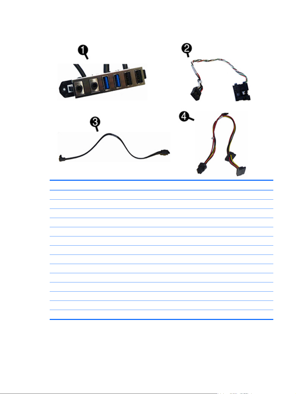
Cables
Item Description
(1) Front I/O assembly
(2) SATA drive power cable
(3) SATA data cable, 14 inch, 1 straight end, 1 angled end
* DMS-59 to dual VGA cable
* DMS-59 to dual DVI cable
* Adapter, DisplayPort to HDMI
* Adapter, DisplayPort to VGA
* Adapter, DisplayPort to DVI
* DisplayPort cable
* Adapter, DVI to VGA
* Adapter, DVI-I to VGA
12 Chapter 2 Illustrated parts catalog
Page 23
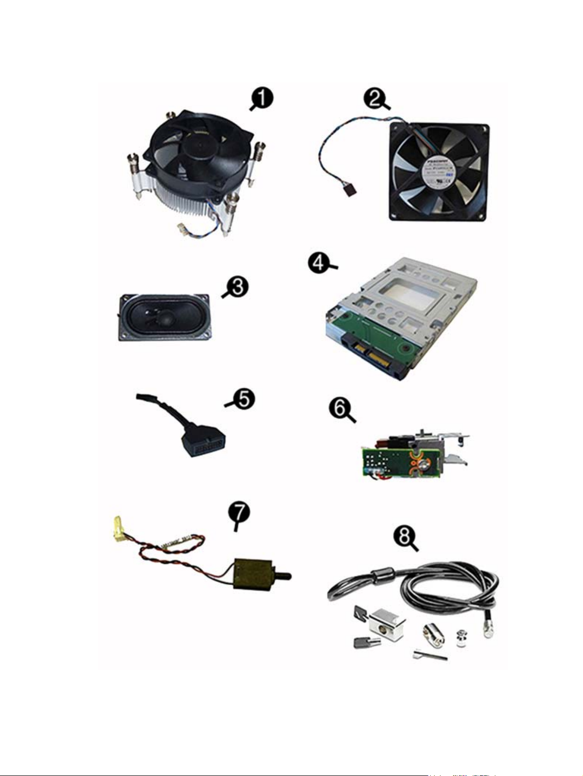
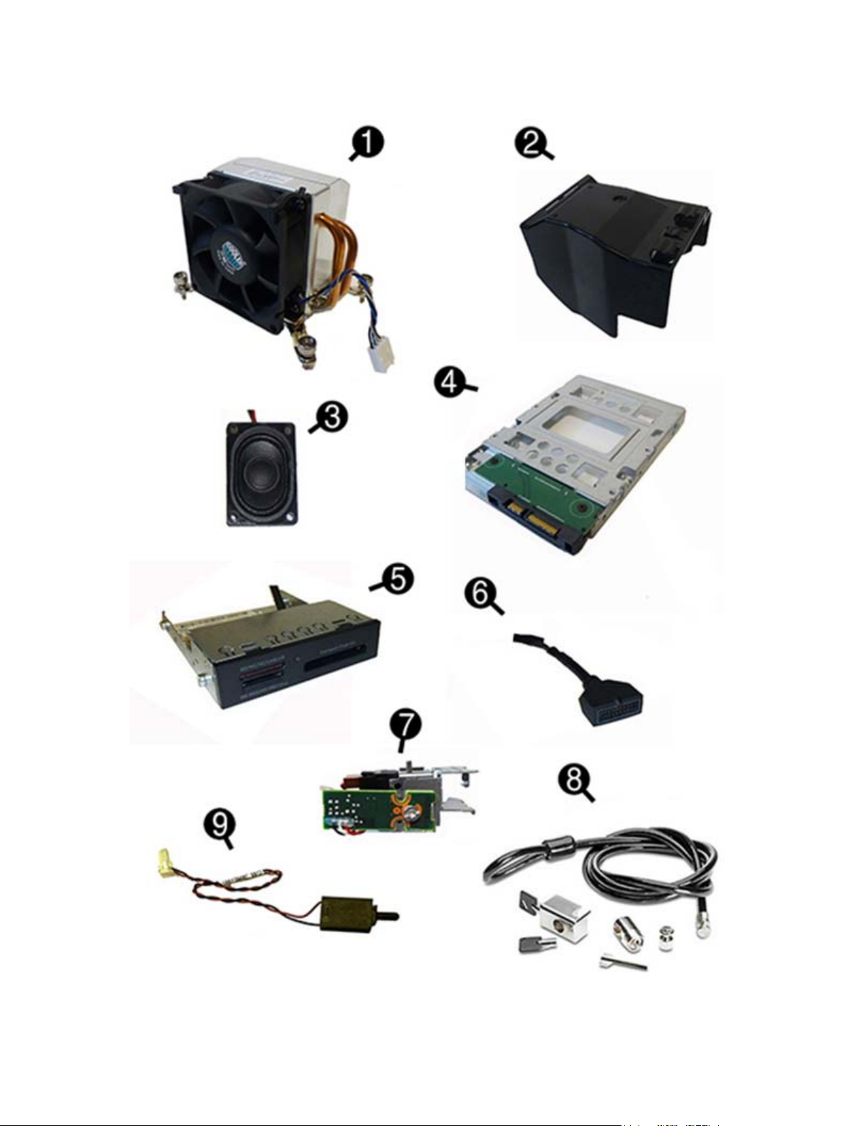
Misc parts
Microtower (MT) chassis spare parts 13
Page 24

Item Description
(1) Fan sink (includes replacement thermal material)
(2) Fan
(3) Speaker
(4) Hard drive conversion bracket, 2.5-inch to 3.5-inch
(5) Adapter, USB 3.0 to USB 2.0 (for use with card reader)
(6) Solenoid lock
(7) Hood sensor
(8) Clamp lock
* Secure Digital (SD) card reader
* Keyed cable lock
* Grommet, hard drive isolation, blue
* Antenna for use with WLAN card
* Antenna cover
* Removable frame carrier (optical drive)
* Mouse
PS2, optical
USB, laser
USB, optical
Washable
Wireless
* Keyboards
PS/2
USB
Wireless
Washable
Smart card
14 Chapter 2 Illustrated parts catalog
Page 25

Drives
Description
Hard drives/Solid-state drives
2-TB, 7200-rpm
1-TB, 10000-rpm, 3.5-inch
1-TB, 7200-rpm, 3.5-inch
1-TB, hybrid SSD, 2.5-inch
500-GB, 10000-rpm
500-GB, 7200-rpm
500 GB, 7200 rpm, 3.5-inch
500-GB, hybrid SSD, 2.5-inch
500-GB, 5400-rpm, 2.5-inch, FIPS
256-GB Solid-state Drive (SSD), self-encrypting (SED)
256-GB Solid-state Drive (SSD)
180 GB Solid-state Drive (SSD)
128-GB Solid-state Drive (SSD), self-encrypting drive (SED)
128-GB Solid-state Drive (SSD)
120-GB Solid-state Drive (SSD)
Optical drives
Blu-ray BD-Writer XL Drive
DVD±RW drive
DVD-ROM drive
Grommet, hard drive isolation, blue
Microtower (MT) chassis spare parts 15
Page 26
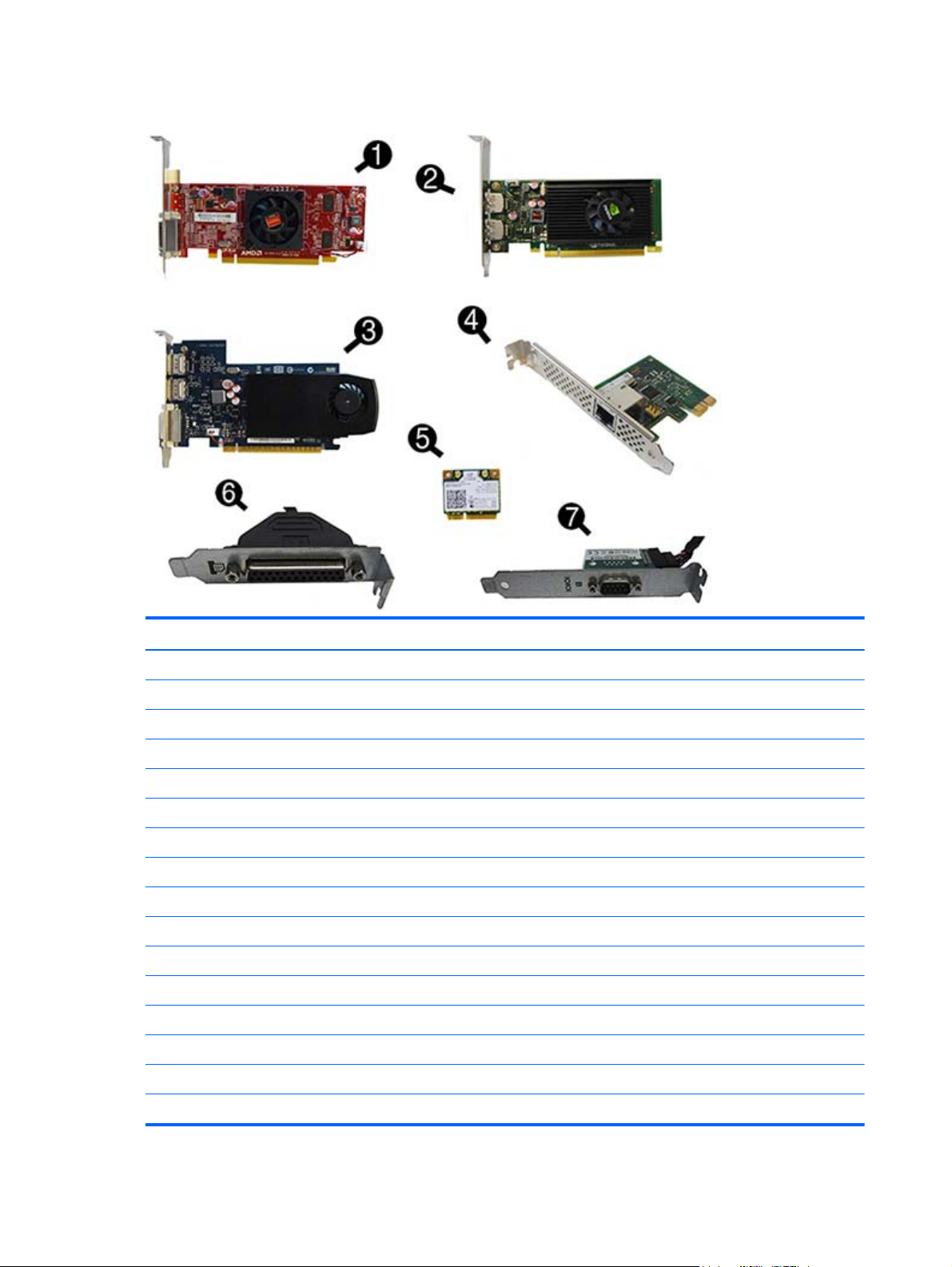
Misc boards
Item Description
(1) AMD Radeon HD8350 DH PCIe x16 graphics card, 1 GB (for use only in China)
* AMD Radeon HD8450 PCIe x16 graphics card, 1 GB
* AMD Radeon HD8470 PCIe x16 graphics card, 1 GB (for use only in China)
* AMD Radeon HD8490 PCIe x16 graphics card, 1 GB
(2) nVidia Quadro NVS310 PCIe x16 graphics card, 512 MB
* nVidia Quadro NVS315 PCIe x16 graphics card, 1 GB
(3) GeForce GT630 PCIe x16 graphics card, 2 GB
* AMD R9 255 graphics processor, 2 GB
* AMD R7 240 graphics processor, 2 GB
(4) Intel PRO/1000 NIC
(5) WLAN 802.11 a/b/g/n + Bluetooth 4.0 module
* HP WLAN 802.11 a/b/g/n 2x2 module
(6) Printer port, PCI card
(7) Serial port, PCI card
* PCIe to M.2 adapter
* 128 GB, M.2 SSD
16 Chapter 2 Illustrated parts catalog
Page 27
Small Form Factor (SFF) chassis spare parts
Computer major components
Item Description
(1) Front bezel
* Bezel blank
(2) Power supply
240W, 92% efficient
240W, 90% efficient
240W, standard
(3) Access panel
(4) System board (includes replacement thermal material)
For use in models without Windows 8.1
Small Form Factor (SFF) chassis spare parts 17
Page 28

Item Description
For use in models with Windows 8.1 Standard
For use in models with Windows 8.1 Professional
For use in NetClone models
(5) Memory modules (PC3-12800, 1600-MHz)
8-GB
4-GB
(6) Processors (include replacement thermal material)
AMD A10-7850B, 3.7 GHz
AMD A10-7800B, 3.57 GHz
AMD A10-6800B, 4.1 GHz
AMD A8-7600B, 3.1 GHz
AMD A8-6500B, 3.5 GHz
AMD A6-7400B, 3.5 GHz
AMD A6-6400B, 3.9 GHz
AMD A4-7300B, 3.9 GHz
AMD A4-6300B, 3.7 GHz
18 Chapter 2 Illustrated parts catalog
Page 29
Cables
Item Description
(1) Front I/O assembly
(2) Power switch assembly
(3) SATA data cable, 14 inch, 1 straight end, 1 angled end
(4) SATA drive power cable
* SATA data cable, 19.5 inch, 2 straight ends
* DMS-59 to dual VGA cable
* DMS-59 to dual DVI cable
* Adapter, DisplayPort to VGA
* Adapter, DisplayPort to DVI
* Adapter, DVI-I to VGA
* Adapter, DVI-D to VGA
* Adapter, DisplayPort to HDMI
* DisplayPort cable
* SATA power extension cable
Small Form Factor (SFF) chassis spare parts 19
Page 30
Misc parts
20 Chapter 2 Illustrated parts catalog
Page 31

Item Description
(1) Fan sink (includes replacement thermal material)
(2) Baffle
(3) Speaker
(4) 2.5-in drive adapter
(5) Card reader, 15-in-1
(6) Adapter, USB 3.0 to USB 2.0 (for use with card reader)
(7) Solenoid lock
(8) Clamp lock, includes universal cable (plate not included)
(9) Hood sensor
* Chassis stand
* Antenna
* Hard drive conversion bracket
* Grommet, hard drive isolation, blue
* Mouse
USB, optical
Washable
Wireless
USB, laser
PS2, optical
* Keyboard
PS/2
USB
USB, mini
Washable
Smart card
Small Form Factor (SFF) chassis spare parts 21
Page 32

Drives
Description
Hard drives/Solid-state drives
2-TB, 7200-rpm
1-TB, 10000-rpm, 3.5-inch
1-TB, hybrid SSD, 2.5-inch
500-GB, 10000-rpm
500-GB, 7200-rpm
500-GB, 7200-rpm, 2.5-inch, self-encrypting (SED)
500-GB, 7200-rpm, 2.5-inch
500-GB, hybrid SSD, 2.5-inch
500-GB, 5400-rpm, 2.5-inch, FIPS
256-GB Solid-state Drive (SSD), self-encrypting (SED)
256-GB Solid-state Drive (SSD)
180 GB Solid-state Drive (SSD)
128-GB Solid-state Drive (SSD), self-encrypting drive (SED)
128-GB Solid-state Drive (SSD)
120-GB Solid-state Drive (SSD)
Optical drives
Blu-ray BD-Writer XL Drive
DVD±RW drive
DVD-ROM drive
Grommet, hard drive isolation, blue
22 Chapter 2 Illustrated parts catalog
Page 33

Misc boards
Item Description
(1) nVidia Quadro NVS310 PCIe x16 graphics card, 512 MB
* nVidia Quadro NVS315 PCIe x16 graphics card, 1 GB
(2) GeForce GT630 PCIe x16 graphics card, 2 GB
* AMD Radeon HD8450 PCIe x16 graphics card, 1 GB
* AMD Radeon HD8490 PCIe x16 graphics card, 1 GB
* AMD R9 255 graphics processor, 2 GB
* AMD R7 240 graphics processor, 2 GB
(3) Intel PRO/1000 NIC
(4) WLAN 802.11 a/b/g/n + Bluetooth 4.0 module
* HP WLAN 802.11 a/b/g/n 2x2 module
(5) Serial port, PCI card
(6) Printer port, PCI card
* PCIe to M.2 adapter
* 128 GB, M.2 SSD (for use with PCIe to M.2 adapter)
Small Form Factor (SFF) chassis spare parts 23
Page 34

Desktop Mini (DM) chassis spare parts
NOTE: HP continually improves and changes product parts. For complete and current information on
supported parts for your computer, go to
follow the on-screen instructions.
Computer major components
http://partsurfer.hp.com, select your country or region, and then
Item Description
(1) Access panel
(2) Front bezel
Stand
Power supply, 120W
(3) System board (includes replacement thermal material)
For use in models without Windows 8.1
For use in models with Windows 8.1 Standard
For use in models with Windows 8.1 Professional
For use in NetClone models
24 Chapter 2 Illustrated parts catalog
Page 35

Cables
Item Description
Memory modules (PC3-12800, 1600-MHz)
8-GB
4-GB
Processors (include replacement thermal material)
AMD A10-7800B, 3.57 GHz
AMD A8-7600B, 3.1 GHz
AMD A6-7400B, 3.5 GHz
AMD A4-7350B, 3.4 GHz
Item Description
(1) SATA power cable
* Wireless antenna cables
* Adapter, DisplayPort to HDMI
* Adapter, DisplayPort to VGA
* Adapter, DisplayPort to DVI
* DisplayPort cable
* USB to serial adapter
Desktop Mini (DM) chassis spare parts 25
Page 36

Misc parts
Item Description
(1) Heat sink
(2) Fan
(3) Speaker
(4) LED cover
* Hood sensor assembly
* Antenna cover
* HP Ultraslim Keyed Cable Lock
* WLAN modules:
* HP WLAN 802.11 a/b/g/n, 2x2
* HP WLAN 802.11 a/b/g/n, for use only in Indonesia
* Mouse
USB, laser
USB, optical
Washable
Wireless
26 Chapter 2 Illustrated parts catalog
Page 37

Drives
Item Description
* Keyboards
USB
Wireless
Washable
Smart card
Description
1 TB, 7200 rpm, hard drive, 2.5-inch, SSHD (hybrid SSD)
500 GB, 7200 rpm hard drive, 2.5-inch
500 GB, 2.5-inch, SSHD (hybrid SSD)
500 GB, 7200 rpm hard drive, 2.5-inch, SED
500 GB, 5400 rpm hard drive, 2.5-inch, FIPS
Solid-state drives
256 GB solid-state drive (SSD), self-encrypting (SED)
180 GB solid-state drive (SSD), SATA 6.0, MLC
128 GB solid-state drive (SSD)
128 GB solid-state drive (SSD), Self-encrypting Drive (SED), SATA 6.0
120 GB solid-state drive (SSD), SATA 6.0, MLC
M.2 drive
128 GB solid-state drive (SSD), M.2
Desktop Mini (DM) chassis spare parts 27
Page 38

3 Routine care, SATA drive guidelines, and
disassembly preparation
This chapter provides general service information for the computer. Adherence to the procedures and
precautions described in this chapter is essential for proper service.
CAUTION: When the computer is plugged into an AC power source, voltage is always applied to the system
board. You must disconnect the power cord from the power source before opening the computer to prevent
system board or component damage.
Electrostatic discharge information
A sudden discharge of static electricity from your finger or other conductor can destroy static-sensitive
devices or microcircuitry. Often the spark is neither felt nor heard, but damage occurs. An electronic device
exposed to electrostatic discharge (ESD) may not appear to be affected at all and can work perfectly
throughout a normal cycle. The device may function normally for a while, but it has been degraded in the
internal layers, reducing its life expectancy.
Networks built into many integrated circuits provide some protection, but in many cases, the discharge
contains enough power to alter device parameters or melt silicon junctions.
Generating static
The following table shows that:
●
Different activities generate different amounts of static electricity.
●
Static electricity increases as humidity decreases.
Relative Humidity
Event 55% 40% 10%
Walking across carpet
Walking across vinyl floor
Motions of bench worker
Removing DIPs from plastic tube
Removing DIPs from vinyl tray
Removing DIPs from Styrofoam
Removing bubble pack from PCB
Packing PCBs in foam-lined box
These are then multi-packaged inside plastic tubes, trays, or Styrofoam.
7,500 V
3,000 V
400 V
400 V
2,000 V
3,500 V
7,000 V
5,000 V
15,000 V
5,000 V
800 V
700 V
4,000 V
5,000 V
20,000 V
11,000 V
35,000 V
12,000 V
6,000 V
2,000 V
11,500 V
14,500 V
26,500 V
21,000 V
NOTE: 700 volts can degrade a product.
28 Chapter 3 Routine care, SATA drive guidelines, and disassembly preparation
Page 39

Preventing electrostatic damage to equipment
Many electronic components are sensitive to ESD. Circuitry design and structure determine the degree of
sensitivity. The following packaging and grounding precautions are necessary to prevent damage to electric
components and accessories.
●
To avoid hand contact, transport products in static-safe containers such as tubes, bags, or boxes.
●
Protect all electrostatic parts and assemblies with conductive or approved containers or packaging.
●
Keep electrostatic sensitive parts in their containers until they arrive at static-free stations.
●
Place items on a grounded surface before removing them from their container.
●
Always be properly grounded when touching a sensitive component or assembly.
●
Avoid contact with pins, leads, or circuitry.
●
Place reusable electrostatic-sensitive parts from assemblies in protective packaging or conductive
foam.
Personal grounding methods and equipment
Use the following equipment to prevent static electricity damage to equipment:
●
Wrist straps are flexible straps with a maximum of one-megohm ± 10% resistance in the ground cords.
To provide proper ground, a strap must be worn snug against bare skin. The ground cord must be
connected and fit snugly into the banana plug connector on the grounding mat or workstation.
●
Heel straps/Toe straps/Boot straps can be used at standing workstations and are compatible with
most types of shoes or boots. On conductive floors or dissipative floor mats, use them on both feet with
a maximum of one-megohm ± 10% resistance between the operator and ground.
Method Voltage
Antistatic plastic
Carbon-loaded plastic
Metallized laminate
Grounding the work area
To prevent static damage at the work area, use the following precautions:
●
Cover the work surface with approved static-dissipative material. Provide a wrist strap connected to the
work surface and properly grounded tools and equipment.
●
Use static-dissipative mats, foot straps, or air ionizers to give added protection.
●
Handle electrostatic sensitive components, parts, and assemblies by the case or PCB laminate. Handle
them only at static-free work areas.
●
Turn off power and input signals before inserting and removing connectors or test equipment.
Static Shielding Protection Levels
1,500
7,500
15,000
●
Use fixtures made of static-safe materials when fixtures must directly contact dissipative surfaces.
●
Keep work area free of nonconductive materials such as ordinary plastic assembly aids and Styrofoam.
●
Use field service tools, such as cutters, screwdrivers, and vacuums, that are conductive.
Electrostatic discharge information 29
Page 40

Recommended materials and equipment
Materials and equipment that are recommended for use in preventing static electricity include:
●
Antistatic tape
●
Antistatic smocks, aprons, or sleeve protectors
●
Conductive bins and other assembly or soldering aids
●
Conductive foam
●
Conductive tabletop workstations with ground cord of one-megohm +/- 10% resistance
●
Static-dissipative table or floor mats with hard tie to ground
●
Field service kits
●
Static awareness labels
●
Wrist straps and footwear straps providing one-megohm +/- 10% resistance
●
Material handling packages
●
Conductive plastic bags
●
Conductive plastic tubes
●
Conductive tote boxes
●
Opaque shielding bags
●
Transparent metallized shielding bags
●
Transparent shielding tubes
Operating guidelines
To prevent overheating and to help prolong the life of the computer:
●
Keep the computer away from excessive moisture, direct sunlight, and extremes of heat and cold.
●
Operate the computer on a sturdy, level surface. Leave a 10.2-cm (4-inch) clearance on all vented sides
of the computer and above the monitor to permit the required airflow.
●
Never restrict the airflow into the computer by blocking any vents or air intakes. Do not place the
keyboard, with the keyboard feet down, directly against the front of the desktop unit as this also
restricts airflow.
●
Occasionally clean the air vents on all vented sides of the computer. Lint, dust, and other foreign matter
can block the vents and limit the airflow. Be sure to unplug the computer before cleaning the air vents.
●
Never operate the computer with the cover or side panel removed.
●
Do not stack computers on top of each other or place computers so near each other that they are
subject to each other’s re-circulated or preheated air.
●
If the computer is to be operated within a separate enclosure, intake and exhaust ventilation must be
provided on the enclosure, and the same operating guidelines listed above will still apply.
●
Keep liquids away from the computer and keyboard.
30 Chapter 3 Routine care, SATA drive guidelines, and disassembly preparation
Page 41

●
Never cover the ventilation slots on the monitor with any type of material.
●
Install or enable power management functions of the operating system or other software, including
sleep states.
Routine care
General cleaning safety precautions
1. Never use solvents or flammable solutions to clean the computer.
2. Never immerse any parts in water or cleaning solutions; apply any liquids to a clean cloth and then use
the cloth on the component.
3. Always unplug the computer when cleaning with liquids or damp cloths.
4. Always unplug the computer before cleaning the keyboard, mouse, or air vents.
5. Disconnect the keyboard before cleaning it.
6. Wear safety glasses equipped with side shields when cleaning the keyboard.
Cleaning the Computer Case
Follow all safety precautions in General cleaning safety precautions on page 31 before cleaning the
computer.
To clean the computer case, follow the procedures described below:
●
To remove light stains or dirt, use plain water with a clean, lint-free cloth or swab.
●
For stronger stains, use a mild dishwashing liquid diluted with water. Rinse well by wiping it with a cloth
or swab dampened with clear water.
●
For stubborn stains, use isopropyl (rubbing) alcohol. No rinsing is needed as the alcohol will evaporate
quickly and not leave a residue.
●
After cleaning, always wipe the unit with a clean, lint-free cloth.
●
Occasionally clean the air vents on the computer. Lint and other foreign matter can block the vents and
limit the airflow.
Cleaning the keyboard
Follow all safety precautions in General cleaning safety precautions on page 31 before cleaning the
keyboard.
To clean the tops of the keys or the keyboard body, follow the procedures described in
Computer Case on page 31.
When cleaning debris from under the keys, review all rules in
before following these procedures:
CAUTION: Use safety glasses equipped with side shields before attempting to clean debris from under the
keys.
Cleaning the
General cleaning safety precautions on page 31
●
Visible debris underneath or between the keys may be removed by vacuuming or shaking.
●
Canned, pressurized air may be used to clean debris from under the keys. Caution should be used as too
much air pressure can dislodge lubricants applied under the wide keys.
Routine care 31
Page 42

●
If you remove a key, use a specially designed key puller to prevent damage to the keys. This tool is
available through many electronic supply outlets.
CAUTION: Never remove a wide leveled key (like the space bar) from the keyboard. If these keys are
improperly removed or installed, the keyboard may not function properly.
●
Cleaning under a key may be done with a swab moistened with isopropyl alcohol and squeezed out. Be
careful not to wipe away lubricants necessary for proper key functions. Use tweezers to remove any
fibers or dirt in confined areas. Allow the parts to air dry before reassembly.
Cleaning the monitor
●
Wipe the monitor screen with a clean cloth moistened with water or with a towelette designed for
cleaning monitors. Do not use sprays or aerosols directly on the screen; the liquid may seep into the
housing and damage a component. Never use solvents or flammable liquids on the monitor.
●
To clean the monitor body follow the procedures in
Cleaning the mouse
Before cleaning the mouse, ensure that the power to the computer is turned off.
●
Clean the mouse ball by first removing the retaining plate and the ball from the housing. Pull out any
debris from the ball socket and wipe the ball with a clean, dry cloth before reassembly.
●
To clean the mouse body, follow the procedures in Cleaning the Computer Case on page 31.
Service considerations
Listed below are some of the considerations that you should keep in mind during the disassembly and
assembly of the computer.
Power supply fan
The power supply fan is a variable-speed fan based on the temperature in the power supply.
CAUTION: The cooling fan is always on when the computer is in the “On” mode. The cooling fan is off when
the computer is in “Standby,” “Suspend,” or “Off” modes.
You must disconnect the power cord from the power source before opening the computer to prevent system
board or component damage.
Cleaning the Computer Case on page 31.
Tools and software Requirements
To service the computer, you need the following:
●
Torx T-15 screwdriver
●
Torx T-15 screwdriver with small diameter shank (for certain front bezel removal)
●
Flat-bladed screwdriver (may sometimes be used in place of the Torx screwdriver)
●
Phillips #2 screwdriver
●
Diagnostics software
●
Tamper-resistant T-15 wrench
32 Chapter 3 Routine care, SATA drive guidelines, and disassembly preparation
Page 43

Screws
The screws used in the computer are not interchangeable. They may have standard or metric threads and
may be of different lengths. If an incorrect screw is used during the reassembly process, it can damage the
unit. HP strongly recommends that all screws removed during disassembly be kept with the part that was
removed, then returned to their proper locations.
CAUTION: Metric screws have a black finish. U.S. screws have a silver finish and are used on hard drives
only.
CAUTION: As each subassembly is removed from the computer, it should be placed away from the work
area to prevent damage.
Cables and connectors
Most cables used throughout the unit are flat, flexible cables. These cables must be handled with care to
avoid damage. Apply only the tension required to seat or unseat the cables during insertion or removal from
the connector. Handle cables by the connector whenever possible. In all cases, avoid bending or twisting the
cables, and ensure that the cables are routed in such a way that they cannot be caught or snagged by parts
being removed or replaced.
CAUTION: When servicing this computer, ensure that cables are placed in their proper location during the
reassembly process. Improper cable placement can damage the computer.
Hard Drives
Handle hard drives as delicate, precision components, avoiding all physical shock and vibration. This applies
to failed drives as well as replacement spares.
●
If a drive must be mailed, place the drive in a bubble-pack mailer or other suitable protective packaging
and label the package “Fragile: Handle With Care.”
●
Do not remove hard drives from the shipping package for storage. Keep hard drives in their protective
packaging until they are actually mounted in the computer.
●
Avoid dropping drives from any height onto any surface.
●
If you are inserting or removing a hard drive, turn off the computer. Do not remove a hard drive while
the computer is on or in standby mode.
●
Before handling a drive, ensure that you are discharged of static electricity. While handling a drive,
avoid touching the connector.
●
Do not use excessive force when inserting a drive.
●
Avoid exposing a hard drive to liquids, temperature extremes, or products that have magnetic fields
such as monitors or speakers.
Lithium coin cell battery
The battery that comes with the computer provides power to the real-time clock and has a minimum lifetime
of about three years.
See the appropriate removal and replacement chapter for the chassis you are working on in this guide for
instructions on the replacement procedures.
WARNING! This computer contains a lithium battery. There is a risk of fire and chemical burn if the battery
is handled improperly. Do not disassemble, crush, puncture, short external contacts, dispose in water or fire,
or expose it to temperatures higher than 140ºF (60ºC). Do not attempt to recharge the battery.
Service considerations 33
Page 44

NOTE: Batteries, battery packs, and accumulators should not be disposed of together with the general
household waste. In order to forward them to recycling or proper disposal, please use the public collection
system or return them to HP, their authorized partners, or their agents.
SATA hard drives
Serial ATA Hard Drive Characteristics
Number of pins/conductors in data cable 7/7
Number of pins in power cable 15
Maximum data cable length 39.37 in (100 cm)
Data interface voltage differential 400-700 mV
Drive voltages 3.3 V, 5 V, 12 V
Jumpers for configuring drive N/A
Data transfer rate 6.0 Gb/s
SATA hard drive cables
SATA data cable
Always use an HP approved SATA 6.0 Gb/s cable as it is fully backwards compatible with the SATA 1.5 Gb/s
drives.
Current HP desktop products ship with SATA 6.0 Gb/s hard drives.
SATA data cables are susceptible to damage if overflexed. Never crease a SATA data cable and never bend it
tighter than a 30 mm (1.18 in) radius.
The SATA data cable is a thin, 7-pin cable designed to transmit data for only a single drive.
SMART ATA drives
The Self Monitoring Analysis and Recording Technology (SMART) ATA drives for the HP Personal Computers
have built-in drive failure prediction that warns the user or network administrator of an impending failure or
crash of the hard drive. The SMART drive tracks fault prediction and failure indication parameters such as
reallocated sector count, spin retry count, and calibration retry count. If the drive determines that a failure is
imminent, it generates a fault alert.
34 Chapter 3 Routine care, SATA drive guidelines, and disassembly preparation
Page 45

Cable management
Always follow good cable management practices when working inside the computer.
●
Keep cables away from major heat sources like the heat sink.
●
Do not jam cables on top of expansion cards or memory modules. Printed circuit cards like these are not
designed to take excessive pressure on them.
●
Keep cables clear of sliding or moveable parts to prevent them from being cut or crimped when the
parts are moved.
●
When folding a flat ribbon cable, never fold to a sharp crease. Sharp creases may damage the wires.
●
Some flat ribbon cables come prefolded. Never change the folds on these cables.
●
Do not bend any cable sharply. A sharp bend can break the internal wires.
●
Never bend a SATA data cable tighter than a 30 mm (1.18 in) radius.
●
Never crease a SATA data cable.
●
Do not rely on components like the drive cage, power supply, or computer cover to push cables down
into the chassis. Always position the cables to lay properly by themselves.
Cable management 35
Page 46

4 Removal and replacement procedures –
Microtower (MT) chassis
Adherence to the procedures and precautions described in this chapter is essential for proper service. After
completing all necessary removal and replacement procedures, run the Diagnostics utility to verify that all
components operate properly.
NOTE: Not all features listed in this guide are available on all computers.
Preparation for disassembly
See Routine care, SATA drive guidelines, and disassembly preparation on page 28 for initial safety
procedures.
1. Remove/disengage any security devices that prohibit opening the computer.
2. Close any open software applications.
3. Exit the operating system.
4. Remove any compact disc or media card from the computer.
5. Turn off the computer and any peripheral devices that are connected to it.
CAUTION: Turn off the computer before disconnecting any cables.
Regardless of the power-on state, voltage is always present on the system board as long as the system
is plugged into an active AC outlet. In some systems the cooling fan is on even when the computer is in
the “Standby,” or “Suspend” modes. The power cord should always be disconnected before servicing a
unit.
6. Disconnect the power cord from the electrical outlet and then from the computer.
7. Disconnect all peripheral device cables from the computer.
8. As applicable, lay the computer down on its side to achieve a safe working position.
NOTE: During disassembly, label each cable as you remove it, noting its position and routing. Keep all
screws with the units removed.
CAUTION: The screws used in the computer are of different thread sizes and lengths; using the wrong
screw in an application may damage the unit.
36 Chapter 4 Removal and replacement procedures – Microtower (MT) chassis
Page 47

Access panel
To access internal components, you must remove the access panel:
1. Prepare the computer for disassembly (
2. Lift up on the access panel handle (1), slide the computer back approximately 12 mm (1/2 inch) (2), and
then lift the access panel off the computer (3).
Preparation for disassembly on page 36)
Access panel 37
Page 48

Front bezel
1. Prepare the computer for disassembly (Preparation for disassembly on page 36)
2. Remove the access panel (
3. Lift up the three tabs on the side of the bezel (1), then rotate the bezel off the chassis (2).
Access panel on page 37)
38 Chapter 4 Removal and replacement procedures – Microtower (MT) chassis
Page 49

Optical drive bezel blank
On some models, there is a bezel blank covering the slim optical drive bay. Remove the bezel blank before
installing an optical drive. To remove the bezel blank:
1. Remove the access panel (
2. Remove the front bezel (
3. To remove the bezel blank, press upward on the bottom tab and press downward on the top tab on the
right side of the blank (1), and then rotate the blank off the front of the bezel (2).
Access panel on page 37)
Front bezel on page 38)
Optical drive bezel blank 39
Page 50

Battery
The battery installed on the computer provides power to the real-time clock. When replacing the battery, use
a battery equivalent to the battery originally installed on the computer. The computer has a 3-volt lithium
coin cell battery installed.
WARNING! The computer contains an internal lithium manganese dioxide battery. There is a risk of fire and
burns if the battery is not handled properly. To reduce the risk of personal injury:
Do not attempt to recharge the battery.
Do not expose to temperatures higher than 60°C (140ºF).
Do not disassemble, crush, puncture, short external contacts, or dispose of in fire or water.
Replace the battery only with the HP spare designated for this product.
CAUTION: Before replacing the battery, it is important to back up the computer CMOS settings. When the
battery is removed or replaced, the CMOS settings will be cleared.
Static electricity can damage the electronic components of the computer or optional equipment. Before
beginning these procedures, ensure that you are discharged of static electricity by briefly touching a
grounded metal object.
NOTE: The lifetime of the lithium battery can be extended by plugging the computer into a live AC wall
socket. The lithium battery is only used when the computer is NOT connected to AC power.
HP encourages customers to recycle used electronic hardware, HP original print cartridges, and rechargeable
batteries. For more information about recycling programs, go to
http://www.hp.com/recycle.
1. Prepare the computer for disassembly (Preparation for disassembly on page 36)
2. Remove the access panel (
3. Locate the battery and battery holder on the system board.
NOTE: On some computer models, it may be necessary to remove an internal component to gain
access to the battery.
4. Depending on the type of battery holder on the system board, complete the following instructions to
replace the battery.
Type 1
a. Lift the battery out of its holder.
Access panel on page 37)
b. Slide the replacement battery into position, positive side up. The battery holder automatically
secures the battery in the proper position.
40 Chapter 4 Removal and replacement procedures – Microtower (MT) chassis
Page 51

Type 2
a. To release the battery from its holder, squeeze the metal clamp that extends above one edge of
the battery. When the battery pops up, lift it out (1).
b. To insert the new battery, slide one edge of the replacement battery under the lip of the holder
with the positive side up. Push the other edge down until the clamp snaps over the other edge of
the battery (2).
Type 3
a. Pull back on the clip (1) that is holding the battery in place, and remove the battery (2).
b. Insert the new battery and position the clip back into place.
NOTE: After the battery has been replaced, use the following steps to complete this procedure.
5. Replace the computer access panel.
6. Plug in the computer and turn on power to the computer.
Battery 41
Page 52

7. Reset the date and time, your passwords, and any special system setups using Computer Setup.
8. Lock any security devices that were disengaged when the computer access panel was removed.
Memory
Description
8-GB, PC3-12800
4-GB, PC3-12800
The computer comes with double data rate 3 synchronous dynamic random access memory (DDR3-SDRAM)
dual inline memory modules (DIMMs).
DIMMs
The memory sockets on the system board can be populated with up to four industry-standard DIMMs. These
memory sockets are populated with at least one preinstalled DIMM. To achieve the maximum memory
support, you can populate the system board with up to 32-GB of memory configured in a high-performing
dual channel mode.
DDR3-SDRAM DIMMs
For proper system operation, the DDR3-SDRAM DIMMs must be:
●
industry-standard 240-pin
●
unbuffered non-ECC PC3-12800 DDR3-1600 MHz-compliant
●
1.5 volt DDR3-SDRAM DIMMs
The DDR3-SDRAM DIMMs must also:
●
support CAS latency 11 DDR3 1600 MHz (11-11-11 timing)
●
contain the mandatory JEDEC SPD information
In addition, the computer supports:
●
512-Mbit, 1-Gbit, and 2-Gbit non-ECC memory technologies
●
single-sided and double-sided DIMMs
●
DIMMs constructed with x8 and x16 DDR devices; DIMMs constructed with x4 SDRAM are not supported
NOTE: The system will not operate properly if you install unsupported DIMMs.
Populating DIMM sockets
There are four DIMM sockets on the system board, with two sockets per channel. The sockets are labeled
DIMM1, DIMM2, DIMM3, and DIMM4. Sockets DIMM1 and DIMM2 operate in memory channel B. Sockets DIMM3
and DIMM4 operate in memory channel A.
The system will automatically operate in single channel mode, dual channel mode, or flex mode, depending
on how the DIMMs are installed.
42 Chapter 4 Removal and replacement procedures – Microtower (MT) chassis
Page 53

NOTE: Single channel and unbalanced dual channel memory configurations will result in inferior graphics
performance.
●
The system will operate in single channel mode if the DIMM sockets are populated in one channel only.
●
The system will operate in a higher-performing dual channel mode if the total memory capacity of the
DIMMs in Channel A is equal to the total memory capacity of the DIMMs in Channel B. The technology
and device width can vary between the channels. For example, if Channel A is populated with two 1-GB
DIMMs and Channel B is populated with one 2-GB DIMM, the system will operate in dual channel mode.
●
The system will operate in flex mode if the total memory capacity of the DIMMs in Channel A is not equal
to the total memory capacity of the DIMMs in Channel B. In flex mode, the channel populated with the
least amount of memory describes the total amount of memory assigned to dual channel and the
remainder is assigned to single channel. For optimal speed, the channels should be balanced so that the
largest amount of memory is spread between the two channels. If one channel will have more memory
than the other, the larger amount should be assigned to Channel A. For example, if you are populating
the sockets with one 2-GB DIMM, and three 1-GB DIMMs, Channel A should be populated with the 2-GB
DIMM and one 1-GB DIMM, and Channel B should be populated with the other two 1-GB DIMMs. With this
configuration, 4-GB will run as dual channel and 1-GB will run as single channel.
●
In any mode, the maximum operational speed is determined by the slowest DIMM in the system.
Installing DIMMs
CAUTION: You must disconnect the power cord and wait approximately 30 seconds for the power to drain
before adding or removing memory modules. Regardless of the power-on state, voltage is always supplied to
the memory modules as long as the computer is plugged into an active AC outlet. Adding or removing
memory modules while voltage is present may cause irreparable damage to the memory modules or system
board.
The memory module sockets have gold-plated metal contacts. When upgrading the memory, it is important
to use memory modules with gold-plated metal contacts to prevent corrosion and/or oxidation resulting
from having incompatible metals in contact with each other.
Static electricity can damage the electronic components of the computer or optional cards. Before beginning
these procedures, ensure that you are discharged of static electricity by briefly touching a grounded metal
object.
When handling a memory module, be careful not to touch any of the contacts. Doing so may damage the
module.
1. Prepare the computer for disassembly (Preparation for disassembly on page 36)
2. Remove the access panel (
Access panel on page 37)
Memory 43
Page 54

3. Open both latches of the memory module socket (1), and insert the memory module into the socket (2).
NOTE: A memory module can be installed in only one way. Match the notch on the module with the tab
on the memory socket.
Populate the black DIMM sockets before the white DIMM sockets.
For maximum performance, populate the sockets so that the memory capacity is spread as equally as
possible between Channel A and Channel B.
4. Push the module down into the socket, ensuring that the module is fully inserted and properly seated.
Make sure the latches are in the closed position (3).
5. Repeat steps 3 and 4 to install any additional modules.
6. Replace the computer access panel.
7. Reconnect the power cord and turn on the computer.
8. Lock any security devices that were disengaged when the access panel was removed.
The computer should automatically recognize the additional memory the next time you turn on the
computer.
44 Chapter 4 Removal and replacement procedures – Microtower (MT) chassis
Page 55

Expansion cards
GeForce GT630 PCIe x16 graphics card, 2 GB
nVidia Quadro NVS315 PCIe x16 graphics card, 1 GB
nVidia Quadro NVS310 PCIe x16 graphics card, 512 MB
AMD Radeon HD8490 PCIe x16 graphics card, 1 GB
AMD Radeon HD8470 PCIe x16 graphics card, 1 GB (for use only in China)
AMD Radeon HD8450 PCIe x16 graphics card, 1 GB
AMD Radeon HD8350 DH PCIe x16 graphics card, 1 GB (for use only in China)
AMD R9 255 graphics processor, 2 GB
AMD R7 240 graphics processor, 2 GB
Intel PRO/1000 NIC
PCIe to M.2 adapter
128 GB, M.2 SSD (for use with PCIe to M.2 adapter)
The computer has two PCI Express x1 expansion slots, one PCI Express x16 expansion slot, and one PCI
Express x16 expansion slot that is downshifted to a x4 slot.
NOTE: You can install a PCI Express x1, x8, or x16 expansion card in the PCI Express x16 slot.
For dual graphics card configurations, the first (primary) card must be installed in the PCI Express x16 slot
that is NOT downshifted to a x4.
To remove, replace, or add an expansion card:
1. Prepare the computer for disassembly (
2. Remove the access panel (
Access panel on page 37)
Preparation for disassembly on page 36)
Expansion cards 45
Page 56

3. Release the slot cover retention latch that secures the slot covers by lifting the tab on the latch and
rotating the latch to the open position.
4. Locate the correct vacant expansion socket on the system board and the corresponding expansion slot
on the back of the computer chassis.
5. Before installing an expansion card, remove the expansion slot cover or the existing expansion card.
NOTE: Before removing an installed expansion card, disconnect any cables that may be attached to
the expansion card.
a. If you are installing an expansion card in a vacant socket, you must slide one of the expansion slot
covers up and out of the chassis or use a flatblade screwdriver to pry out one of the metal shields
on the rear panel that covers the expansion slot. Be sure to remove the appropriate shield for the
expansion card you are installing.
46 Chapter 4 Removal and replacement procedures – Microtower (MT) chassis
Page 57

b. If you are removing a PCI Express x1 card, hold the card at each end and carefully rock it back and
forth until the connectors pull free from the socket. Lift the card straight up (1) then away from
the inside of the chassis (2) to remove it. Be sure not to scrape the card against other components.
c. If you are removing a PCI Express x16 card, pull the retention arm on the back of the expansion
socket away from the card and carefully rock the card back and forth until the connectors pull free
from the socket. Lift the card straight up then away from the inside of the chassis to remove it. Be
sure not to scrape the card against other components.
6. Store the removed card in anti-static packaging.
7. If you are not installing a new expansion card, install an expansion slot cover to close the open slot.
CAUTION: After removing an expansion card, you must replace it with a new card or expansion slot
cover for proper cooling of internal components during operation.
Expansion cards 47
Page 58

8. To install a new expansion card, hold the card just above the expansion socket on the system board
then move the card toward the rear of the chassis (1) so that the bottom of the bracket on the card
slides into the small slot on the chassis. Press the card straight down into the expansion socket on the
system board (2).
NOTE: When installing an expansion card, press firmly on the card so that the whole connector seats
properly in the expansion card slot.
9. Rotate the slot cover retention latch back in place to secure the expansion card.
10. Connect external cables to the installed card, if needed. Connect internal cables to the system board, if
needed.
11. Replace the computer access panel.
12. Reconnect the power cord and turn on the computer.
13. Lock any security devices that were disengaged when the computer access panel was removed.
14. Reconfigure the computer, if necessary.
48 Chapter 4 Removal and replacement procedures – Microtower (MT) chassis
Page 59

Drives
Description
Hard drives/Solid-state drives
2-TB, 7200-rpm
1-TB, 10000-rpm, 3.5-inch
1-TB, 7200-rpm, 3.5-inch
1-TB, hybrid SSD, 2.5-inch
500-GB, 10000-rpm
500-GB, 7200-rpm
500 GB, 7200 rpm, 3.5-inch
500-GB, hybrid SSD, 2.5-inch
500-GB, 5400-rpm, 2.5-inch, FIPS
256-GB Solid-state Drive (SSD), self-encrypting (SED)
256-GB Solid-state Drive (SSD)
180 GB Solid-state Drive (SSD)
128-GB Solid-state Drive (SSD), self-encrypting drive (SED)
128-GB Solid-state Drive (SSD)
120-GB Solid-state Drive (SSD)
Optical drives
DVD±RW drive
DVD-ROM drive
Blu-ray BD-Writer XL Drive
When installing drives, follow these guidelines:
●
The primary Serial ATA (SATA) hard drive must be connected to the dark blue primary SATA connector
on the system board labeled SATA0.
●
Connect secondary hard drives and optical drives to one of the light blue SATA connectors on the
system board (labeled SATA1 and SATA2).
Drives 49
Page 60

●
HP has provided four extra 6-32 silver mounting screws installed next to the hard drive bays (1). The
mounting screws are required for hard drives installed in the upper (secondary) hard drive bay. If you
are replacing a primary hard drive in the lower bay, remove the silver and blue mounting screws from
the old drive and install them in the new drive.
CAUTION: To prevent loss of work and damage to the computer or drive:
If you are inserting or removing a drive, shut down the operating system properly, turn off the computer, and
unplug the power cord. Do not remove a drive while the computer is on or in standby mode.
Before handling a drive, ensure that you are discharged of static electricity. While handling a drive, avoid
touching the connector.
Handle a drive carefully; do not drop it.
Do not use excessive force when inserting a drive.
Avoid exposing a hard drive to liquids, temperature extremes, or products that have magnetic fields such as
monitors or speakers.
If a drive must be mailed, place the drive in a bubble-pack mailer or other protective packaging and label the
package “Fragile: Handle With Care.”
50 Chapter 4 Removal and replacement procedures – Microtower (MT) chassis
Page 61

Drive positions
1 Slim optical drive bay
2 3.5-inch secondary hard drive bay
3 3.5-inch primary hard drive bay
NOTE: The drive configuration on your computer may be different than the drive configuration shown above.
To verify the type and size of the storage devices installed in the computer, run Computer Setup.
Removing a slim optical drive
1. Prepare the computer for disassembly (Preparation for disassembly on page 36)
2. Remove the access panel (
3. Remove the front bezel (
4. Disconnect the power cable and data cable from the back of the optical drive.
CAUTION: When removing the cables, pull the tab or connector instead of the cable itself to avoid
damaging the cable.
Access panel on page 37)
Front bezel on page 38)
Drives 51
Page 62

5. Push inward on the green release latch on the underside of the drive (1) and push the rear of the drive
forward to unlock it (2), and then slide the drive out of the drive bay (3).
Installing a slim optical drive
1. Prepare the computer for disassembly (Preparation for disassembly on page 36).
2. Remove the access panel (
3. Remove the front bezel (
bezel blank, remove the bezel blank. See
4. Follow the instructions for removing the optical drive if one was installed. Refer to
optical drive on page 51.
5. Align the small pins on the release latch with the small holes on the side of the drive and press the latch
firmly onto the drive.
Access panel on page 37).
Front bezel on page 38). If you are installing a device in a bay covered by a
Optical drive bezel blank on page 39 for more information.
Removing a slim
52 Chapter 4 Removal and replacement procedures – Microtower (MT) chassis
Page 63

6. Slide the optical drive all the way into the drive bay (1) until the green latch locks onto the bottom of the
drive bay (2).
7. Connect the power cable and data cable to the back of the optical drive.
8. If installing a new drive, connect the opposite end of the data cable to one of the light blue SATA
connectors (labeled SATA1 and SATA2) on the system board.
9. Replace the front bezel.
10. Replace the computer access panel.
11. Reconnect the power cord and any external devices, then turn on the computer.
12. Lock any security devices that were disengaged when the access panel was removed.
Removing a hard drive
NOTE: Before you remove the old hard drive, be sure to back up the data from the old hard drive so that
you can transfer the data to the new hard drive.
1. Prepare the computer for disassembly (Preparation for disassembly on page 36).
2. Remove the access panel (
3. Disconnect the power cable and data cable from the back of the hard drive.
Access panel on page 37).
Drives 53
Page 64

4. Pull the green latch next to the drive outward (1) and slide the drive out of the bay (2).
Installing a hard drive
1. Prepare the computer for disassembly (Preparation for disassembly on page 36).
2. Remove the access panel (
3. You can install a 3.5-inch hard drive or a 2.5-inch hard drive with a 3.5-inch adapter bracket similar to
the example shown below.
●
Slide the 2.5-inch drive into the bay adapter bracket, ensuring the connector on the drive is fully
inserted into the connector on the adapter bracket.
Access panel on page 37).
54 Chapter 4 Removal and replacement procedures – Microtower (MT) chassis
Page 65

●
Secure the drive to the bay adapter bracket by installing four black M3 adapter bracket screws
through the sides of the bracket into the drive.
4. Install four mounting screws into the sides of the drive (two on each side).
NOTE: The lower hard drive bay requires silver and blue mounting screws. The upper hard drive bay
requires all silver mounting screws. HP has supplied four extra silver mounting screws installed on the
chassis next to the hard drives that are used when installing a hard drive in the upper drive bay. Refer to
Drives on page 49 for an illustration of the location of the extra mounting screws. When replacing a
hard drive in the lower bay, use the four silver and blue mounting screws that were removed from the
old drive to install the new drive.
●
If installing a hard drive in the upper (secondary) drive bay, use the extra silver mounting screws
that can be retrieved from the chassis next to the hard drive bays.
Drives 55
Page 66

●
If installing a hard drive in the lower (primary) drive bay, remove the silver and blue mounting
screws from the old drive and install them in the new drive.
5. Slide the drive into the drive bay, making sure to align the mounting screws with the guide slots, until
the drive snaps into place.
56 Chapter 4 Removal and replacement procedures – Microtower (MT) chassis
Page 67

6. Connect the power cable (1) and data cable (2) to the back of the hard drive.
NOTE: The power cable for the hard drives is a two-headed cable that is routed from the power supply
to the rear of the hard drive bays.
7. If installing a new drive, connect the opposite end of the data cable to the appropriate system board
connector.
NOTE: You must connect the primary hard drive data cable to the dark blue connector labeled SATA0
to avoid any hard drive performance problems. If you are adding a second hard drive, connect the data
cable to one of the light blue SATA connector labeled SATA1 and SATA2.
8. Replace the computer access panel.
9. Reconnect the power cord and any external devices, then turn on the computer.
10. Lock any security devices that were disengaged when the access panel was removed.
Drives 57
Page 68

Drive power cable
1. Prepare the computer for disassembly (Preparation for disassembly on page 36).
2. Remove the computer access panel (
3. Disconnect the cable from the optical drive (1) and the hard drive (2)
4. Remove the cable from the clips on the base pan and on the side of the hard drive cage (3).
5. Disconnect the cable from the system board connector labeled SATAPWR0 (4), and then remove the
cable from the computer.
Access panel on page 37).
To reinstall the drive power cable, reverse the removal procedure.
58 Chapter 4 Removal and replacement procedures – Microtower (MT) chassis
Page 69

Front I/O and power switch assembly
1. Prepare the computer for disassembly (Preparation for disassembly on page 36).
2. Remove the computer access panel (
3. Remove the front bezel (
4. Remove the Torx T15 screw (1) that secures the assembly to the chassis, and then push the tab on the
right side of the assembly (2) to disengage it from the chassis.
Front bezel on page 38).
Access panel on page 37).
5. Remove the cables from the clips on the base pan.
Front I/O and power switch assembly 59
Page 70

6. Rotate the assembly into the chassis (1).
7. Disconnect the four cables from the following system board connectors:
(2): Front USB (yellow)
(3): Front AUD (blue)
(4): Front USB3.0 (blue)
(5): PB/LED (black)
8. Remove the assembly from the inside of the computer.
To reinstall the assembly, reverse the removal procedure.
60 Chapter 4 Removal and replacement procedures – Microtower (MT) chassis
Page 71

Heat sink
CAUTION: The bond between the heat sink and the processor may be very tight.
If the computer will power on, before removing the heat sink, turn on the computer until it warms the heat
sink. Warming the heat sink lessens the bond between the heat sink and the processor, thereby making
separating them easier.
Make sure not to pull the processor out of the socket when you lift the heat sink, especially if you cannot
warm the heat sink prior to removal. Inadvertently removing the processor can damage the pins.
1. Prepare the computer for disassembly (Preparation for disassembly on page 36).
2. Remove the access panel (
3. Disconnect the fan cable from the system board connector labeled CPUFAN (1).
4. Loosen the four silver captive Torx T15 screws (2) that secure the heat sink to the system board.
CAUTION: Remove heat sink retaining screws in diagonally opposite pairs (as in an X) to even the
downward forces on the processor. The pins on the socket are very fragile and any damage to them may
require replacing the system board.
5. Lift the heat sink from atop the processor (3).
Access panel on page 37).
When reinstalling the heat sink, make sure that its bottom has been cleaned with an alcohol wipe and fresh
thermal grease has been applied to the top of the processor.
CAUTION: Heat sink retaining screws should be tightened in diagonally opposite pairs (as in an X) to evenly
seat the heat sink on the processor. This is especially important as the pins on the socket are very fragile and
any damage to them may require replacing the system board.
Heat sink 61
Page 72

Processor
Description
AMD A10-7850B processor, 3.7 GHz
AMD A10-7800B processor, 3.57 GHz
AMD A10-6800B processor, 4.1 GHz
AMD A8-7600B processor, 3.1 GHz
AMD A8-6500B processor, 3.5 GHz
AMD A6-7400B processor, 3.5 GHz
AMD A6-6400B processor, 3.9 GHz
AMD A4-7300B processor, 3.9 GHz
AMD A4-6300B processor, 3.7 GHz
1. Prepare the computer for disassembly (Preparation for disassembly on page 36).
2. Remove the access panel (
3. Remove the heat sink (
Access panel on page 37).
Heat sink on page 61).
4. Rotate the locking lever to its full open position (1).
5. Carefully lift the processor from the socket (2).
CAUTION: Do NOT handle the pins in the processor socket. These pins are very fragile and handling
them could cause irreparable damage. Once pins are damaged it may be necessary to replace the
system board.
The heat sink must be installed within 24 hours of installing the processor to prevent damage to the
processor’s solder connections.
Reverse the removal procedure to install a new processor.
62 Chapter 4 Removal and replacement procedures – Microtower (MT) chassis
Page 73

NOTE: After installing a new processor onto the system board, update the system ROM to ensure that the
latest version of the BIOS is being used on the computer. The latest system BIOS can be found on the Web at:
http://h18000.www1.hp.com/support/files.
Speaker
1. Prepare the computer for disassembly (Preparation for disassembly on page 36).
2. Remove the access panel (
3. Remove the speaker cable from the clip on the base pan.
Access panel on page 37).
4. Disconnect the speaker wire from the system board connector labeled SPKR (1).
5. From the inside of the chassis, remove the silver Torx T15 screw (2) that secures the speaker to the
chassis.
Speaker 63
Page 74

6. Remove the speaker from the chassis (3).
To replace the speaker, reverse the removal procedures.
64 Chapter 4 Removal and replacement procedures – Microtower (MT) chassis
Page 75

Rear chassis fan
1. Prepare the computer for disassembly (Preparation for disassembly on page 36).
2. Remove the access panel (
3. Remove the three silver Phillips screws that secure the fan to the rear of chassis.
4. Disconnect the fan control cable (1) from the system board connector labeled CHFAN2.
5. Lift the fan out of the chassis (2).
Access panel on page 37).
To install the fan assembly, reverse the removal procedure. Be sure to orient the air flow out of the unit.
Rear chassis fan 65
Page 76

Power supply
Description
Power supply, 280W, 92% efficient
Power supply, 280W, 90% efficient
Power supply, 280W, 85% efficient (for use only in China)
Power supply, 280W, standard
1. Prepare the computer for disassembly (Preparation for disassembly on page 36).
2. Remove the access panel (
Access panel on page 37).
3. Remove the four silver Torx T15 screws that connect the power supply to the chassis.
66 Chapter 4 Removal and replacement procedures – Microtower (MT) chassis
Page 77

4. Remove the power cable from the clip on the base pan.
5. Disconnect the power supply cable from the PWR system board connector (1) and the PWRCPU system
board connector (2).
6. Press the tab (3) on the base pan in front of the power supply that holds it in place.
7. Slide the power supply toward the front of the computer, rotate toward the fan so the power supply
clears the lip on the top of the chassis, and then lift the power supply out of the chassis (4).
Power supply 67
Page 78

To install the power supply, reverse the removal procedure.
System board
Description
System board for use in models without Windows 8.1
System board for use in models with Windows 8.1 Standard
System board for use in models with Windows 8.1 Professional
System board for use in NetClone models
1. Prepare the computer for disassembly (Preparation for disassembly on page 36).
2. Remove the access panel (
Access panel on page 37).
3. When replacing the system board, make sure the following components are removed from the defective
system board and installed on the replacement system board:
●
Memory modules (
●
Expansion cards (
●
Heat sink (
●
Processor (
Heat sink on page 61).
Processor on page 62)
Memory on page 42)
Expansion cards on page 45)
4. Disconnect all cables connected to the system board, noting their location for reinstallation.
5. Remove the eight Torx T15 screws that secure the system board to the chassis.
68 Chapter 4 Removal and replacement procedures – Microtower (MT) chassis
Page 79

6. Slide the system board toward the front of the computer to disengage the I/O panel (1), and then lift the
system board out of the computer (2).
When reinstalling the system board, first insert the I/O panel back into the slots in the rear of the chassis, and
then align the board with the chassis screw holes.
NOTE: When replacing the system board, you must change the chassis serial number in the BIOS.
System board 69
Page 80

System board callouts
Sys Bd Label Sys Bd
Connector
CHFAN2 Chassis fan
connector
HSENSE Hood sensor
connector
PWRCPU Processor
power
connector
XU1 Processor Green Processor
CPUFAN Processor fan
connector
DIMM4 DIMM4
(Channel A)
DIMM3 DIMM3
(Channel A)
Color Component Sys Bd Label Sys Bd
Red Fan SPKR Speaker
White Hood sensor FRONT USB Front I/O
White 4-pin processor
power
(soldered on)
White Processor fan FRONT AUD Front I/O
White Memory module X4PCIEXP PCI Express
Black Memory module X1PCIEXP2 PCI Express x1 Black Expansion card
Connector
connector
connector
CMOS CMOS button Yellow Reset CMOS
BAT Battery
socket
connector
x16
downshifted
to x4
Color Component
White Speaker
Yellow Front I/O
Black RTC battery
Blue Front I/O
Black Expansion card
70 Chapter 4 Removal and replacement procedures – Microtower (MT) chassis
Page 81

DIMM2 DIMM2
(Channel B)
White Memory module X1PCIEXP1 PCI Express x1 Black Expansion card
DIMM1 DIMM1
(Channel B)
PSWD Password
jumper
PB/LED Front I/O Black Front I/O/power
PWRCMD Power supply
connector
SATAPWR0 Drive power
connector
PWR Power
connector
FRONT
USB3.0
SATA2 SATA 3.0 Light
SATA1 SATA 3.0 Light
SATA0 SATA 3.0 Dark
Front I/O Blue Front I/O/power
Black Memory module X16PCIEXP PCI Express
Green Clear system
passwords
switch
White Power supply USB USB ports Silver USB ports
Black Drives COMB Serial Port Black Optional second
White 24-pin main
power connector
switch
Optical drive or
blue
blue
blue
second hard drive
Optical drive or
second hard drive
Hard drive PS2 PS/2
White Expansion card
x16
PAR Parallel port Black Optional parallel
port
IN/OUT Input and
output jacks
Serial/VGA Display
connector/
Serial port
connector
DISPLAYPORT DisplayPort Silver DisplayPort
DISPLAYPORT DisplayPort Silver DisplayPort
RJ45/USB Network/USB
port
connector
Silver Headphone and
microphone jacks
serial port
Silver VGA and serial
port connectors
connector
connector
Silver Network
connector and
USB ports
Silver Mouse and
keyboard
System board 71
Page 82

5 Removal and replacement procedures –
small form factor (SFF) chassis
Adherence to the procedures and precautions described in this chapter is essential for proper service. After
completing all necessary removal and replacement procedures, run the Diagnostics utility to verify that all
components operate properly.
NOTE: Not all features listed in this guide are available on all computers.
Preparation for disassembly
See Routine care, SATA drive guidelines, and disassembly preparation on page 28 for initial safety
procedures.
1. Remove/disengage any security devices that prohibit opening the computer.
2. Close any open software applications.
3. Exit the operating system.
4. Remove any compact disc or media card from the computer.
5. Turn off the computer and any peripheral devices that are connected to it.
CAUTION: Turn off the computer before disconnecting any cables.
Regardless of the power-on state, voltage is always present on the system board as long as the system
is plugged into an active AC outlet. In some systems the cooling fan is on even when the computer is in
the “Standby,” or “Suspend” modes. The power cord should always be disconnected before servicing a
unit.
6. Disconnect the power cord from the electrical outlet and then from the computer.
7. Disconnect all peripheral device cables from the computer.
NOTE: During disassembly, label each cable as you remove it, noting its position and routing. Keep all
screws with the units removed.
CAUTION: The screws used in the computer are of different thread sizes and lengths; using the wrong
screw in an application may damage the unit.
8. If the computer is on a stand, remove the computer from the stand.
72 Chapter 5 Removal and replacement procedures – small form factor (SFF) chassis
Page 83

Access panel
1. Prepare the computer for disassembly (Preparation for disassembly on page 72).
2. Lift up on the access panel handle (1) then lift the access panel off the computer (2).
To install the access panel, reverse the removal procedure.
Front bezel
1. Prepare the computer for disassembly (Preparation for disassembly on page 72).
2. Remove the access panel (
3. Lift up the three tabs on the side of the bezel (1), then rotate the bezel off the chassis (2).
To install the front bezel, reverse the removal procedure.
Access panel on page 73).
Access panel 73
Page 84

Front bezel security
The front bezel can be locked in place by installing a security screw provided by HP. To install the security
screw:
1. Prepare the computer for disassembly (
2. Remove the access panel (
3. Remove one of the five silver 6-32 standard screws located on top of the drive cage.
4. Install the security screw through the middle front bezel release tab to secure the front bezel in place.
Access panel on page 73).
Preparation for disassembly on page 72).
5. Replace the access panel.
6. If the computer was on a stand, replace the stand.
7. Reconnect the power cord and turn on the computer.
8. Lock any security devices that were disengaged when the access panel was removed.
74 Chapter 5 Removal and replacement procedures – small form factor (SFF) chassis
Page 85

Bezel blanks
On some models, there are bezel blanks covering the 3.5-inch and slim optical drive bays that need to be
removed before installing a drive. To remove a bezel blank:
1. Prepare the computer for disassembly (
2. Remove the access panel (
3. Remove the front bezel (
4. To remove a slim optical drive bezel blank, press inward on the four retaining tabs (1) and pull the blank
off the front bezel (2).
To remove a 3.5-inch bezel blank, press the two retaining tabs that hold the bezel blank in place
towards the outer right edge of the bezel (3) and slide the bezel blank back and to the right to remove it
(4).
Access panel on page 73).
Front bezel on page 73).
Preparation for disassembly on page 72).
NOTE: After removing the slim optical drive bezel blank and installing a slim optical drive, you can install an
optional bezel trim piece (available from HP) that surrounds the front of the slim optical drive.
Bezel blanks 75
Page 86

Battery
The battery installed on the computer provides power to the real-time clock. When replacing the battery, use
a battery equivalent to the battery originally installed on the computer. The computer has a 3-volt lithium
coin cell battery installed.
WARNING! The computer contains an internal lithium manganese dioxide battery. There is a risk of fire and
burns if the battery is not handled properly. To reduce the risk of personal injury:
Do not attempt to recharge the battery.
Do not expose to temperatures higher than 60°C (140ºF).
Do not disassemble, crush, puncture, short external contacts, or dispose of in fire or water.
Replace the battery only with the HP spare designated for this product.
CAUTION: Before replacing the battery, it is important to back up the computer CMOS settings. When the
battery is removed or replaced, the CMOS settings will be cleared.
Static electricity can damage the electronic components of the computer or optional equipment. Before
beginning these procedures, ensure that you are discharged of static electricity by briefly touching a
grounded metal object.
NOTE: The lifetime of the lithium battery can be extended by plugging the computer into a live AC wall
socket. The lithium battery is only used when the computer is NOT connected to AC power.
HP encourages customers to recycle used electronic hardware, HP original print cartridges, and rechargeable
batteries. For more information about recycling programs, go to
http://www.hp.com/recycle.
1. Prepare the computer for disassembly (Preparation for disassembly on page 72).
2. Remove the access panel (
3. Locate the battery and battery holder on the system board.
NOTE: On some computer models, it may be necessary to remove an internal component to gain
access to the battery.
4. Depending on the type of battery holder on the system board, complete the following instructions to
replace the battery.
Type 1
a. Lift the battery out of its holder.
Access panel on page 73)
b. Slide the replacement battery into position, positive side up. The battery holder automatically
secures the battery in the proper position.
76 Chapter 5 Removal and replacement procedures – small form factor (SFF) chassis
Page 87

Type 2
a. To release the battery from its holder, squeeze the metal clamp that extends above one edge of
the battery. When the battery pops up, lift it out (1).
b. To insert the new battery, slide one edge of the replacement battery under the lip of the holder
with the positive side up. Push the other edge down until the clamp snaps over the other edge of
the battery (2).
Type 3
a. Pull back on the clip (1) that is holding the battery in place, and remove the battery (2).
b. Insert the new battery and position the clip back into place.
NOTE: After the battery has been replaced, use the following steps to complete this procedure.
5. Replace the computer access panel.
6. Plug in the computer and turn on power to the computer.
Battery 77
Page 88

7. Reset the date and time, your passwords, and any special system setups using Computer Setup.
8. Lock any security devices that were disengaged when the computer access panel was removed.
Memory
Description
8-GB, PC3-12800
4-GB, PC3-12800
The computer comes with double data rate 3 synchronous dynamic random access memory (DDR3-SDRAM)
dual inline memory modules (DIMMs).
DIMMs
The memory sockets on the system board can be populated with up to four industry-standard DIMMs. These
memory sockets are populated with at least one preinstalled DIMM. To achieve the maximum memory
support, you can populate the system board with up to 32-GB of memory configured in a high-performing
dual channel mode.
DDR3-SDRAM DIMMs
For proper system operation, the DDR3-SDRAM DIMMs must be:
●
industry-standard 240-pin
●
unbuffered non-ECC PC3-12800 DDR3-1600 MHz-compliant
●
1.5 volt DDR3-SDRAM DIMMs
The DDR3-SDRAM DIMMs must also:
●
support CAS latency 11 DDR3 1600 MHz (11-11-11 timing)
●
contain the mandatory JEDEC SPD information
In addition, the computer supports:
●
512-Mbit, 1-Gbit, and 2-Gbit non-ECC memory technologies
●
single-sided and double-sided DIMMs
●
DIMMs constructed with x8 and x16 DDR devices; DIMMs constructed with x4 SDRAM are not supported
NOTE: The system will not operate properly if you install unsupported DIMMs.
Populating DIMM sockets
There are four DIMM sockets on the system board, with two sockets per channel. The sockets are labeled
DIMM1, DIMM2, DIMM3, and DIMM4. Sockets DIMM1 and DIMM2 operate in memory channel B. Sockets DIMM3
and DIMM4 operate in memory channel A.
The system will automatically operate in single channel mode, dual channel mode, or flex mode, depending
on how the DIMMs are installed.
78 Chapter 5 Removal and replacement procedures – small form factor (SFF) chassis
Page 89

NOTE: Single channel and unbalanced dual channel memory configurations will result in inferior graphics
performance.
●
The system will operate in single channel mode if the DIMM sockets are populated in one channel only.
●
The system will operate in a higher-performing dual channel mode if the total memory capacity of the
DIMMs in Channel A is equal to the total memory capacity of the DIMMs in Channel B. The technology
and device width can vary between the channels. For example, if Channel A is populated with two 1-GB
DIMMs and Channel B is populated with one 2-GB DIMM, the system will operate in dual channel mode.
●
The system will operate in flex mode if the total memory capacity of the DIMMs in Channel A is not equal
to the total memory capacity of the DIMMs in Channel B. In flex mode, the channel populated with the
least amount of memory describes the total amount of memory assigned to dual channel and the
remainder is assigned to single channel. For optimal speed, the channels should be balanced so that the
largest amount of memory is spread between the two channels. If one channel will have more memory
than the other, the larger amount should be assigned to Channel A. For example, if you are populating
the sockets with one 2-GB DIMM, and three 1-GB DIMMs, Channel A should be populated with the 2-GB
DIMM and one 1-GB DIMM, and Channel B should be populated with the other two 1-GB DIMMs. With this
configuration, 4-GB will run as dual channel and 1-GB will run as single channel.
●
In any mode, the maximum operational speed is determined by the slowest DIMM in the system.
Installing DIMMs
CAUTION: You must disconnect the power cord and wait approximately 30 seconds for the power to drain
before adding or removing memory modules. Regardless of the power-on state, voltage is always supplied to
the memory modules as long as the computer is plugged into an active AC outlet. Adding or removing
memory modules while voltage is present may cause irreparable damage to the memory modules or system
board.
The memory module sockets have gold-plated metal contacts. When upgrading the memory, it is important
to use memory modules with gold-plated metal contacts to prevent corrosion and/or oxidation resulting
from having incompatible metals in contact with each other.
Static electricity can damage the electronic components of the computer or optional cards. Before beginning
these procedures, ensure that you are discharged of static electricity by briefly touching a grounded metal
object.
When handling a memory module, be careful not to touch any of the contacts. Doing so may damage the
module.
1. Prepare the computer for disassembly (Preparation for disassembly on page 72).
2. Remove the access panel (
3. Rotate up the internal drive bay housing to access the memory module sockets on the system board.
Access panel on page 73).
Memory 79
Page 90

4. Open both latches of the memory module socket (1), and insert the memory module into the socket (2).
NOTE: A memory module can be installed in only one way. Match the notch on the module with the tab
on the memory socket.
Populate the black DIMM sockets before the white DIMM sockets.
For maximum performance, populate the sockets so that the memory capacity is spread as equally as
possible between Channel A and Channel B. Refer to
information.
5. Push the module down into the socket, ensuring that the module is fully inserted and properly seated.
Make sure the latches are in the closed position (3).
6. Repeat steps 4 and 5 to install any additional modules.
7. Replace the access panel.
8. If the computer was on a stand, replace the stand.
9. Reconnect the power cord and turn on the computer.
10. Lock any security devices that were disengaged when the access panel was removed.
The computer should automatically recognize the additional memory the next time you turn on the
computer.
Populating DIMM sockets on page 78 for more
80 Chapter 5 Removal and replacement procedures – small form factor (SFF) chassis
Page 91

Expansion card
GeForce GT630 PCIe x16 graphics card, 2 GB
nVidia Quadro NVS315 PCIe x16 graphics card, 1 GB
nVidia Quadro NVS310 PCIe x16 graphics card, 512 MB
AMD Radeon HD8490 PCIe x16 graphics card, 1 GB
AMD Radeon HD8450 PCIe x16 graphics card, 1 GB
AMD R9 255 graphics processor, 2 GB
AMD R7 240 graphics processor, 2 GB
Intel PRO/1000 NIC
PCIe to M.2 adapter
128 GB, M.2 SSD (for use with PCIe to M.2 adapter)
The computer has two PCI Express x1 expansion slots, one PCI Express x16 expansion slot, and one PCI
Express x16 expansion slot that is downshifted to a x4 slot.
NOTE: The PCI Express slots support only low profile cards.
You can install a PCI Express x1, x4, x8, or x16 expansion card in the PCI Express x16 slot.
For dual graphics card configurations, the first (primary) card must be installed in the PCI Express x16 slot
that is NOT downshifted to a x4.
To remove, replace, or add an expansion card:
1. Prepare the computer for disassembly (
2. Remove the access panel (
Access panel on page 73).
Preparation for disassembly on page 72).
3. Locate the correct vacant expansion socket on the system board and the corresponding expansion slot
on the back of the computer chassis.
Expansion card 81
Page 92

4. Release the slot cover retention latch that secures the slot covers by lifting the green tab on the latch
and rotating the latch to the open position.
5. Before installing an expansion card, remove the expansion slot cover or the existing expansion card.
NOTE: Before removing an installed expansion card, disconnect any cables that may be attached to
the expansion card.
a. If you are installing an expansion card in a vacant socket, remove the appropriate expansion slot
cover on the back of the chassis. Pull the slot cover straight up then away from the inside of the
chassis.
82 Chapter 5 Removal and replacement procedures – small form factor (SFF) chassis
Page 93

b. If you are removing a PCI Express x1 card, hold the card at each end, and carefully rock it back and
forth until the connectors pull free from the socket. Pull the expansion card straight up from the
socket (1) then away from the inside of the chassis to release it from the chassis frame (2). Be sure
not to scrape the card against the other components.
c. If you are removing a PCI Express x16 card, pull the retention arm on the back of the expansion
socket away from the card and carefully rock the card back and forth until the connectors pull free
from the socket. Pull the expansion card straight up from the socket then away from the inside of
the chassis to release it from the chassis frame. Be sure not to scrape the card against the other
components.
6. Store the removed card in anti-static packaging.
7. If you are not installing a new expansion card, install an expansion slot cover to close the open slot.
CAUTION: After removing an expansion card, you must replace it with a new card or expansion slot
cover for proper cooling of internal components during operation.
Expansion card 83
Page 94

8. To install a new expansion card, hold the card just above the expansion socket on the system board
then move the card toward the rear of the chassis (1) so that the bracket on the card is aligned with the
open slot on the rear of the chassis. Press the card straight down into the expansion socket on the
system board (2).
NOTE: When installing an expansion card, press firmly on the card so that the whole connector seats
properly in the expansion card slot.
9. Rotate the slot cover retention latch back in place to secure the expansion card.
10. Connect external cables to the installed card, if needed. Connect internal cables to the system board, if
needed.
11. Replace the computer access panel.
12. If the computer was on a stand, replace the stand.
13. Reconnect the power cord and turn on the computer.
14. Lock any security devices that were disengaged when the access panel was removed.
15. Reconfigure the computer, if necessary.
84 Chapter 5 Removal and replacement procedures – small form factor (SFF) chassis
Page 95

Drives
Description
Hard drives/Solid-state drives
2-TB, 7200-rpm
1-TB, 10000-rpm, 3.5-inch
1-TB, hybrid SSD, 2.5-inch
500-GB, 10000-rpm
500-GB, 7200-rpm
500-GB, 7200-rpm, 2.5-inch, self-encrypting (SED)
500-GB, 7200-rpm, 2.5-inch
500-GB, hybrid SSD, 2.5-inch
500-GB, 5400-rpm, 2.5-inch, FIPS
256-GB Solid-state Drive (SSD), self-encrypting (SED)
256-GB Solid-state Drive (SSD)
180 GB Solid-state Drive (SSD)
128-GB Solid-state Drive (SSD), self-encrypting drive (SED)
128-GB Solid-state Drive (SSD)
120-GB Solid-state Drive (SSD)
Optical drives
DVD±RW drive
DVD-ROM drive
Blu-ray BD-Writer XL Drive
Drives 85
Page 96

Drive positions
1 Slim optical drive bay
2 3.5-inch internal hard drive bay
3 3.5-inch drive bay for optional drives (media card reader shown)
4 2.5-inch internal hard drive bay
NOTE: The drive configuration on your computer may be different than the drive
configuration shown above.
To verify the type and size of the storage devices installed in the computer, run Computer Setup.
Installing and Removing Drives
When installing drives, follow these guidelines:
●
The primary Serial ATA (SATA) hard drive must be connected to the dark blue primary SATA connector
on the system board labeled SATA0.
●
Connect secondary hard drives and optical drives to one of the light blue SATA connectors on the
system board (labeled SATA1 and SATA2).
●
Connect a media card reader USB 2.0 cable to the USB connector on the system board labeled MEDIA.
●
The power cable for the drives has two branches coming off the system board connector. The first
branch is a dual-headed cable with the first connector (four-wire) routed to the 3.5-inch optional drive
bay and the second connector (two-wire) routed to the slim optical drive bay. The second branch is a
dual-headed cable with the first connector routed to the 3.5-inch hard drive bay and the second
connector routed to the 2.5-inch hard drive bay.
86 Chapter 5 Removal and replacement procedures – small form factor (SFF) chassis
Page 97

●
You must install guide screws to ensure the drive will line up correctly in the drive cage and lock in
place. HP has provided four extra 6-32 standard guide screws installed on the top of the drive bay. The
6-32 standard guide screws are required for a media card reader or a secondary hard drive installed in
the 3.5-inch optional drive bay. M3 isolation mounting guide screws for 2.5-inch hard drives are not
provided. If you are replacing a drive, remove the guide screws from the old drive and install them in the
new drive.
There are a total of five extra silver 6-32 standard screws. One is used for bezel security (1) (see Installing
and Removing Drives on page 86 for more information). The other four are used as guide screws for a media
card reader or a secondary hard drive in the 3.5-inch optional drive bay (2).
CAUTION: To prevent loss of work and damage to the computer or drive:
If you are inserting or removing a drive, shut down the operating system properly, turn off the computer, and
unplug the power cord. Do not remove a drive while the computer is on or in standby mode.
Before handling a drive, ensure that you are discharged of static electricity. While handling a drive, avoid
touching the connector.
Handle a drive carefully; do not drop it.
Do not use excessive force when inserting a drive.
Avoid exposing a hard drive to liquids, temperature extremes, or products that have magnetic fields such as
monitors or speakers.
If a drive must be mailed, place the drive in a bubble-pack mailer or other protective packaging and label the
package “Fragile: Handle With Care.”
Drives 87
Page 98

Removing a 3.5-inch device
CAUTION: All removable media should be taken out of a drive before removing the drive from the
computer.
1. Prepare the computer for disassembly (Preparation for disassembly on page 72).
2. Remove the access panel (
3. Remove the front bezel (
4. Rotate the drive cage to its upright position.
5. Disconnect the drive cables from the rear of the drive, or, if you are removing a media card reader,
disconnect the USB cable from the system board as indicated in the following illustration.
Access panel on page 73).
Front bezel on page 73).
88 Chapter 5 Removal and replacement procedures – small form factor (SFF) chassis
Page 99

6. Press inward on the release lever at the rear of the drive (1) and slide the drive out of the rear of the
drive bay (2).
Installing a 3.5-inch device
1. Prepare the computer for disassembly (Preparation for disassembly on page 72).
2. Remove the access panel (
3. Remove the front bezel (
blank, remove the bezel blank. See
4. Install 6-32 guide screws in the holes on each side of the drive.
NOTE: HP has supplied four extra 6-32 guide screws on top of the drive cage. Refer to
Removing Drives on page 86 for an illustration of the location of the extra guide screws.
When replacing a drive, transfer the four 6-32 guide screws from the old drive to the new one.
Access panel on page 73).
Front bezel on page 73). If you are installing a drive in a bay covered by a bezel
Bezel blanks on page 75 for more information.
Installing and
5. Rotate the drive cage to its upright position.
Drives 89
Page 100

6. Slide the drive into the drive bay, making sure to align the guide screws with the guide slots, until the
drive snaps into place.
7. If installing a USB 3.0 media card reader, you must use the USB 3.0 to USB 2.0 adapter (1) and connect
the adapter cable from the media card reader to the USB 2.0 connector on the system board labeled
MEDIA (2).
NOTE: Refer to System board callouts on page 118 for an illustration of the system board drive
connectors.
90 Chapter 5 Removal and replacement procedures – small form factor (SFF) chassis
 Loading...