

HP Color LaserJet 3000, Color LaserJet 3600, Color LaserJet 3800, Color LaserJet CP3505 Service Manual
Page 1
HP Color LaserJet 3000/3600/
3800/CP3505 Series Printer
Service Manual
Page 2

Page 3

HP Color LaserJet 3000/3600/3800/
CP3505 Series Printer
Service Manual
Page 4

Copyright and license
Trademark credits
© 2007 Copyright Hewlett-Packard
Development Company, L.P.
Reproduction, adaptation, or translation
without prior written permission is
prohibited, except as allowed under the
copyright laws.
The information contained herein is subject
to change without notice.
The only warranties for HP products and
services are set forth in the express
warranty statements accompanying such
products and services. Nothing herein
should be construed as constituting an
additional warranty. HP shall not be liable
for technical or editorial errors or omissions
contained herein.
Edition 1, 6/2007
Part number Q5982-91034
Microsoft® and Windows® are U.S.
registered trademarks of Microsoft
Corporation.
Linux is a U.S. registered trademark of
Linus Torvalds.
PostScript® is a trademarks of Adobe
Systems Incorporated.
UNIX® is a registered trademark of The
Open Group.
Energy Star® and the Energy Star® logo
are U.S. registered marks of the United
States Environmental Protection Agency.
Page 5

Table of contents
1 Product information
Quick access to printer information ....................................................................................................... 2
Printers at a glance ................................................................................................................................ 3
HP Color LaserJet 3000 Series printer ................................................................................. 3
HP Color LaserJet 3600 Series printer ................................................................................. 4
HP Color LaserJet 3800 Series printer ................................................................................. 4
HP Color LaserJet CP3505 Series printer ............................................................................ 5
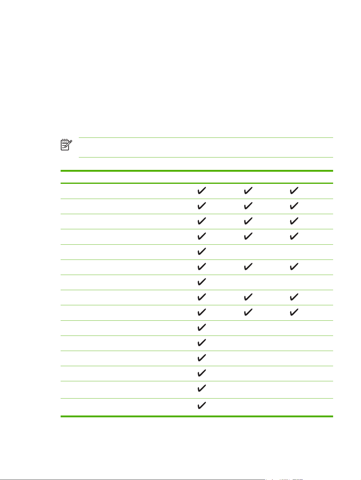
Features at a glance .............................................................................................................................. 6
Walkaround ............................................................................................................................................ 8
Control-panel overview ........................................................................................................................ 10
Control-panel indicator lights .............................................................................................. 11
Display ................................................................................................................................ 11
Printer software .................................................................................................................................... 13
HP Color LaserJet 3000 Series printer, HP Color LaserJet 3800 Series printer, and
HP Color LaserJet CP3505 Series printer drivers .............................................................. 13
HP Color LaserJet 3600 Series printer drivers ................................................................... 14
Additional drivers ................................................................................................................ 15
Software for networks ......................................................................................................... 15
HP Web Jetadmin .............................................................................................. 15
UNIX ................................................................................................................... 15
Linux ................................................................................................................... 15
Utilities ................................................................................................................................. 16
HP Easy Printer Care Software ......................................................................... 16
Embedded Web server ...................................................................................... 16
Other components and utilities .......................................................................... 16
Print-media specifications .................................................................................................................... 17
Supported paper and print media sizes .............................................................................. 17
Media type and tray loading ................................................................................................ 18
2 Installation and configuration
What is in the box ................................................................................................................................ 22
Site requirements ................................................................................................................................ 23
Physical specifications ........................................................................................................ 2 3
Connecting to a network or a computer .............................................................................................. 24
Printer memory .................................................................................................................................... 26
Installing memory DIMMs ................................................................................................... 26
To install memory DIMMs .................................................................................. 26
Enabling memory ............................................................................................... 29
To enable memory for Windows ....................................................... 29
ENWW iii
Page 6

3 Maintenance
Understanding approximate supplies-replacement intervals .............................................................. 32
Replacing supplies .............................................................................................................................. 33
Managing the print cartridge ................................................................................................................ 34
Cleaning the printer ............................................................................................................................. 38
Calibrating the printer .......................................................................................................
Tools for troubleshooting ..................................................................................................................... 40
Checking DIMM installation ............................................................................... 29
To check DIMM installation ............................................................... 29
Locating supplies ................................................................................................................ 33
Supply replacement guidelines ........................................................................................... 33
HP print cartridges .............................................................................................................. 34
Non-HP print cartridges ...................................................................................................... 34
Print-cartridge authentication .............................................................................................. 34
Print-cartridge storage ........................................................................................................ 34
Print-cartridge life expectancy ............................................................................................ 34
Checking the supply level ................................................................................................... 35
Using the control panel ...................................................................................... 35
Using the embedded Web server ...................................................................... 35
Using HP Web Jetadmin .................................................................................... 35
Replacing print cartridges .................................................................................. 35
To replace the print cartridge ............................................................ 36
Cleaning spilled toner ......................................................................................................... 38
Vacuum specifications ....................................................................................... 38
................... 39
Using printer information pages .......................................................................................... 40
Configuring e-mail alerts ..................................................................................................... 41
Using the embedded Web server ....................................................................................... 41
To open the embedded Web server by using a network connection ................ 42
Embedded Web server sections ........................................................................ 43
Using the HP Easy Printer Care Software .......................................................................... 44
Supported operating systems ............................................................................ 44
To use the HP Easy Printer Care Software ....................................................... 45
HP Easy Printer Care Software sections ........................................................... 45
Using the HP Printer Utility for Macintosh .......................................................................... 46
To open the HP Printer Utility in Mac OS X V10.2 ............................................. 46
To open the HP Printer Utility in Mac OS X V10.3 ............................................. 46
HP Printer Utility features ................................................................................... 46
4 Theory of operation
Engine control system ......................................................................................................................... 50
Power-on sequence ............................................................................................................ 51
Motors, fans, and solenoids ................................................................................................ 52
Laser/scanner system ......................................................................................................................... 54
Pickup-and-feed-system ...................................................................................................................... 55
Sensors in the pickup-and-feed system trays (cassettes) .................................................. 56
Cassette pickup mechanism ............................................................................................... 57
Multipurpose-tray pickup mechanism ................................................................................. 58
Feed-speed control ............................................................................................................. 5 8
Sensor jam detection .......................................................................................................... 60
iv ENWW
Page 7

Image-formation system ...................................................................................................................... 63
Image-formation process .................................................................................................... 64
Latent-image formation stage ............................................................................................. 65
Developing stage ................................................................................................................ 66
Transfer stage ..................................................................................................................... 66
Fusing stage ....................................................................................................................... 68
Cleaning stage .................................................................................................................... 68
Print cartridge ...................................................................................................................... 69
Print-cartridge activation ..................................................................................................... 70
5 Removal and replacement
Removal and replacement strategy ..................................................................................................... 72
Introduction ......................................................................................................................... 72
Required tools ..................................................................................................................... 73
Types of screws .................................................................................................................. 74
Service approach ................................................................................................................ 75
Before performing service ................................................................................................... 75
After performing service ...................................................................................................... 75
Print cartridges .................................................................................................................... 76
External doors, covers, and panels ..................................................................................................... 77
Front cover .......................................................................................................................... 77
Upper cover (fuser door) ..................................................................................................... 82
Rear lower cover ................................................................................................................. 85
Left cover ............................................................................................................................ 86
Right cover .......................................................................................................................... 89
Rear upper cover ..............................................................................................................
Internal assemblies .............................................................................................................................. 94
Formatter cage .................................................................................................................... 94
Electrostatic transfer belt (ETB) .......................................................................................... 96
Fuser ................................................................................................................................... 97
Duplex fan ........................................................................................................................... 98
Print-cartridge drive motors .............................................................................................. 101
Duplex-reverse-drive assembly ........................................................................................ 102
Duplex-feed-drive assembly ............................................................................................. 105
Fuser drive assembly ........................................................................................................ 107
Developing separation-drive assembly ............................................................................. 110
Pickup-and-feed assembly ............................................................................................... 113
Pickup-drive assembly ...................................................................................................... 119
Laser/scanner assembly ................................................................................................... 128
Main fan ............................................................................................................................ 132
Step 1: pre-exposure .......................................................................................... 65
Step 2: primary charging .................................................................................... 66
Step 3: laser-beam exposure ............................................................................. 66
Step 4: developing ............................................................................................. 66
Step 5: media feed ............................................................................................. 67
Step 6: image transfer ........................................................................................ 67
Step 7: separation from the drum ...................................................................... 67
Step 8: separation from the ETB ........................................................................ 68
Step 9: fusing ..................................................................................................... 68
Step 10: drum cleaning ...................................................................................... 69
.. 93
ENWW v
Page 8

Printed circuit assemblies (PCAs) ..................................................................................................... 134
Sensors .............................................................................................................................................. 152
500-sheet feeder ............................................................................................................................... 159
6 Troubleshooting
Troubleshooting process ................................................................................................................... 172
Control-panel messages .................................................................................................................... 176
Jams .................................................................................................................................................. 200
Image defects .................................................................................................................................... 215
Low-voltage power-supply PCA ........................................................................................ 134
DC controller PCA ............................................................................................................. 138
High-voltage power supply ............................................................................................... 140
Memory-controller PCA .................................................................................................... 142
Driver PCA ........................................................................................................................ 144
Control panel ..................................................................................................................... 146
Pickup-and-feed driver PCA ............................................................................................. 148
Duplex-driver PCA ............................................................................................................ 150
Cassette media sensor (HP LaserJet 3600/3800/CP3505) ............................................. 152
Temperature sensor ......................................................................................................... 154
Paper and registration sensor covers ............................................................................... 155
Cartridge-sensor PCA ....................................................................................................... 156
500-sheet feeder right cover ............................................................................................. 159
500-sheet feeder left cover ............................................................................................... 161
500-sheet feeder rear cover ............................................................................................. 164
500-sheet feeder driver PCA ............................................................................................ 166
Media sensor (500-sheet feeder) ..................................................................................... 168
Pre-troubleshooting checklist ............................................................................................ 172
Troubleshooting flowchart ................................................................................................. 174
Power-on checks .............................................................................................................. 175
Jam recovery ..................................................................................................................
Avoiding jams .................................................................................................................... 201
Clearing jams .................................................................................................................... 202
Image-formation troubleshooting ...................................................................................... 212
Print-quality problems associated with media .................................................. 212
Defects on overhead transparencies ................................................................................ 213
Print-quality problems that are related to the environment .............................................. 214
Print-quality problems that are related to jams ................................................................. 214
Print-quality problems from toner buildup ......................................................................... 214
Print-quality troubleshooting pages .................................................................................. 214
Light image ....................................................................................................................... 216
Light color ......................................................................................................................... 216
Dark image ........................................................................................................................ 217
Dark color .......................................................................................................................... 218
Completely blank image ................................................................................................... 218
All black or solid color ....................................................................................................... 218
Dots in vertical lines .......................................................................................................... 218
Dirt on back of paper ........................................................................................................ 219
Dirt on front of paper ......................................................................................................... 219
Vertical lines ..................................................................................................................... 220
White vertical lines ............................................................................................................ 220
.. 200
vi ENWW
Page 9

Horizontal line ................................................................................................................... 220
White horizontal line ......................................................................................................... 221
Color missing .................................................................................................................... 221
Blank spots ....................................................................................................................... 222
Poor fusing ........................................................................................................................ 222
Image distortion ................................................................................................................ 222
Color misregistration ......................................................................................................... 223
Smearing ........................................................................................................................... 223
Misplaced image ............................................................................................................... 224
Reversed color .................................................................................................................. 224
Snail tracks ....................................................................................................................... 224
Repetitive-defects troubleshooting .................................................................................................... 225
Interface troubleshooting ................................................................................................................... 227
Communication checks ..................................................................................................... 227
EIO troubleshooting .......................................................................................................... 227
Service menu ..................................................................................................................................... 228
Using the Service menu .................................................................................................... 228
Clear event log .................................................................................................................. 228
Total page count ............................................................................................................... 228
Serial number .................................................................................................................... 228
Diagnostics menu .............................................................................................................................. 229
Diagnostics ........................................................................................................................................ 230
LED diagnostics ................................................................................................................ 230
Diagnostics mode ............................................................................................................. 230
Diagnostics that put the engine into the special diagnostics mode ................. 231
Diagnostic tests ................................................................................................................. 231
Individual diagnostic tests ................................................................................................. 232
Print the event log page ................................................................................... 232
View the event log on the control-panel display .............................................. 232
Print the print-quality (PQ) troubleshooting pages ........................................... 233
Disable cartridge check (special mode test) .................................................... 233
Paper-path sensor test ..................................................................................... 233
Paper-path test ................................................................................................. 233
Manual sensor test (special mode test) ........................................................... 234
Component test (special mode test) ................................................................ 235
Print/Stop test ................................................................................................... 237
Test pages ......................................................................................................................................... 238
Engine test page ............................................................................................................... 238
Formatter test .................................................................................................................... 238
Half-self test ...................................................................................................................... 238
Drum-rotation test ............................................................................................................. 239
Engine resets ..................................................................................................................................... 240
Engine resets .................................................................................................................... 240
Cold reset ......................................................................................................... 240
NVRAM initialization ......................................................................................... 240
Hard-disk initialization ...................................................................................... 241
Service ID .......................................................................................................................................... 242
Converting the Service ID to an actual date ..................................................................... 242
Restoring the Service ID ................................................................................................... 242
Troubleshooting diagrams ................................................................................................ 243
ENWW vii
Page 10

7 Parts and diagrams
Ordering parts and supplies .............................................................................................................. 258
Parts .................................................................................................................................. 258
How to use the parts lists and diagrams ........................................................................... 258
Types of screws ................................................................................................................ 258
Related documentation and software ............................................................................... 259
Accessories and supplies ................................................................................................. 259
External panels and covers ............................................................................................................... 264
Internal components .......................................................................................................................... 272
Paper-pickup drive assembly ............................................................................................................ 282
Duplexing-feed drive assembly (duplex models) .............................................................................. 284
Duplexing reverse-drive assembly (duplex models) ......................................................................... 286
Developing separation-drive assembly ............................................................................................. 288
Fuser drive assembly ........................................................................................................................ 290
Cassette (tray 2) ................................................................................................................................ 292
Paper-pickup assembly (HP CLJ 3600/3800/CP3505) ..................................................................... 294
Paper-pickup assembly (HP CLJ 3000) ............................................................................................ 296
Electronic transfer belt (simplex models) .......................................................................................... 298
Electronic transfer belt (duplex models) ............................................................................................ 300
Multipurpose tray assembly (tray 1) .................................................................................................. 302
Duplex-paper feed assembly (duplex models) .................................................................................. 304
Fuser .................................................................................................................................................. 306
PCAs .................................................................................................................................................. 308
500-sheet feeder cassette (tray 3) .................................................................................................... 310
500-sheet feeder paper-pickup assembly ......................................................................................... 312
500-sheet feeder PCA ....................................................................................................................... 314
Alphabetical parts list ......................................................................................................................... 316
Numerical parts list ............................................................................................................................ 326
Connector locations ......................................................................................... 243
Major assemblies ............................................................................................. 245
DC controller connectors ................................................................................. 250
Timing diagram ................................................................................................ 251
Circuit diagrams ............................................................................................... 253
Appendix A Printer specifications
Electrical specifications ..................................................................................................................... 338
Power-consumption specifications .................................................................................................... 339
Acoustic specifications ...................................................................................................................... 340
Operating-environment specifications ............................................................................................... 341
Appendix B Product warranty statements
Hewlett-Packard Limited Warranty Statement .................................................................................. 344
Availability of support and service ..................................................................................................... 345
HP maintenance agreements ............................................................................................................ 345
Next-Day Onsite Service .................................................................................................. 345
Appendix C Regulatory statements
FCC regulations ................................................................................................................................. 348
viii ENWW
Page 11

Declaration of conformity (HP Color LaserJet 3000 Series printer) .................................................. 349
Declaration of conformity (HP Color LaserJet 3600 Series and HP Color LaserJet 3800 Series
printer) ............................................................................................................................................... 350
Declaration of conformity (HP Color LaserJet CP3505 Series printer) ............................................. 351
Safety statements .............................................................................................................................. 352
Laser safety ...................................................................................................................... 352
Canadian DOC regulations ............................................................................................... 352
EMI statement (Korea) ...................................................................................................... 352
VCCI statement (Japan) ................................................................................................... 352
Power cord statement (Japan) .......................................................................................... 352
Laser statement for Finland .............................................................................................. 353
Index .................................................................................................................................................................. 355
ENWW ix
Page 12

x ENWW
Page 13

1 Product information
Quick access to printer information
●
Printers at a glance
●
Features at a glance
●
Walkaround
●
Control-panel overview
●
Printer software
●
Print-media specifications
●
ENWW 1
Page 14

Quick access to printer information
Several references are available for use with this printer.
HP Color LaserJet 3000 Series printer:
●
HP Color LaserJet 3600 Series printer:
●
HP Color LaserJet 3800 Series printer:
●
HP Color LaserJet CP3505 Series printer:
●
Table 1-1 Printer guides
Guide Description
Getting started guide Provides step-by-step instructions for installing and setting up the printer.
HP Jetdirect Embedded Print
Server Administrators Guide
Accessory and consumable
installation guides
User guide Provides detailed information for using and troubleshooting the printer. Available on the
Online Help Provides information about options that are available in the printer drivers. To view a
Provides instructions to configure and troubleshoot the HP Jetdirect print server.
Provide step-by-step instructions for installing the accessories and supplies. These
guides are supplied with the optional printer accessories and supplies.
printer CD.
Help file, open the online Help through the printer driver.
www.hp.com/support/clj3000.
www.hp.com/support/clj3600.
www.hp.com/support/clj3800.
http://www.hp.com/support/cljcp3505.
2 Chapter 1 Product information ENWW
Page 15
Printers at a glance
The HP Color LaserJet 3000, 3600, 3800, and CP3505 Series printers are available in the following
configurations.
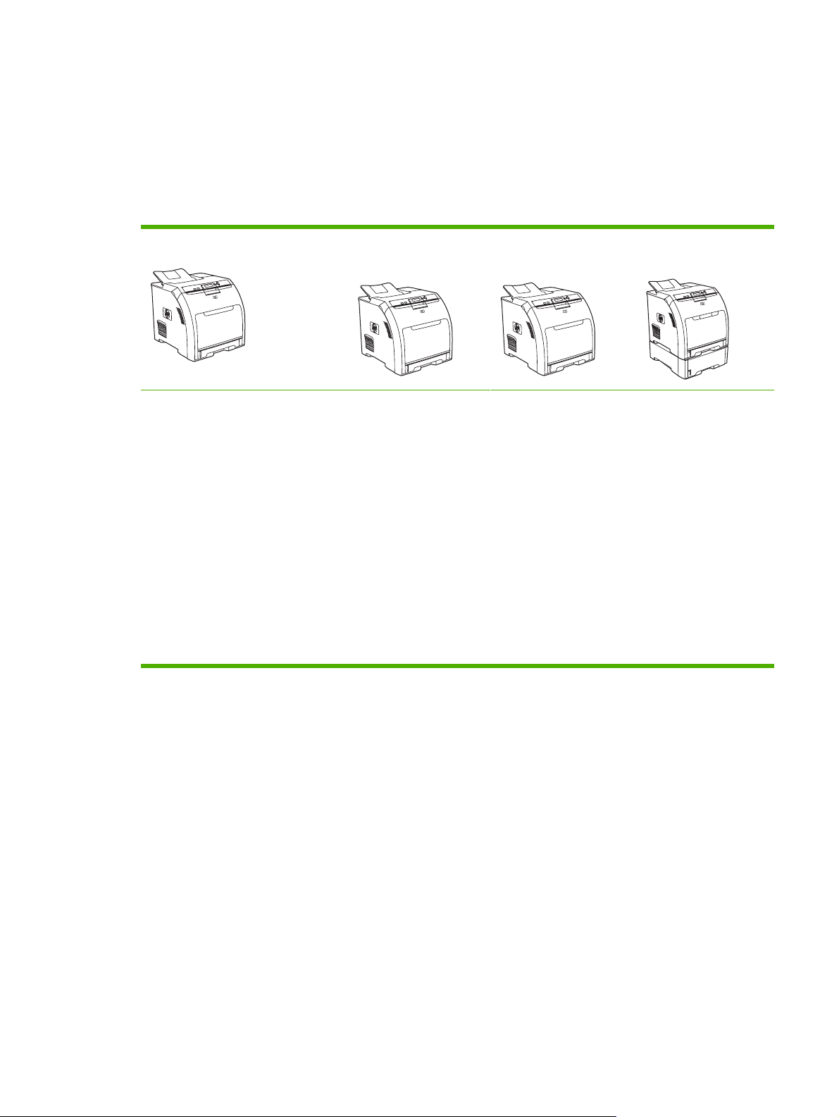
HP Color LaserJet 3000 Series printer
Table 1-2 HP Color LaserJet 3000 Series printer configurations
HP Color LaserJet 3000 printer HP Color LaserJet
Prints up to 30 pages per minute
●
(ppm) on letter-size media or
29 ppm on A4-size media in
monochrome (black and white)
and 15 ppm in color
100-sheet multipurpose tray
●
(tray 1) and 250-sheet input tray
(tray 2)
● Hi-Speed universal serial bus
(USB) 2.0 port and enhanced
input/output (EIO) slot
64 MB RAM
●
3000n printer
The features of the
HP Color LaserJet 3000
printer, plus:
64 MB RAM (128
●
total)
HP Jetdirect full-
●
featured embedded
print server to
connect to 10BaseT/100 Base-TX
networks
HP Color LaserJet
3000dn printer
The features of the
HP Color LaserJet 3000
printer, plus:
192 MB RAM (256
●
total)
HP Jetdirect full-
●
featured embedded
print server to
connect to 10BaseT/100 Base-TX
networks
Automatic 2-sided
●
(duplex) printing
HP Color LaserJet
3000dtn printer
The features of the
HP Color LaserJet 3000
printer, plus:
192 MB RAM (256
●
total)
HP Jetdirect full-
●
featured embedded
print server to
connect to 10BaseT/100 Base-TX
networks
Automatic 2-sided
●
(duplex) printing
● 500-sheet input tray
(tray 3)
ENWW Printers at a glance 3
Page 16
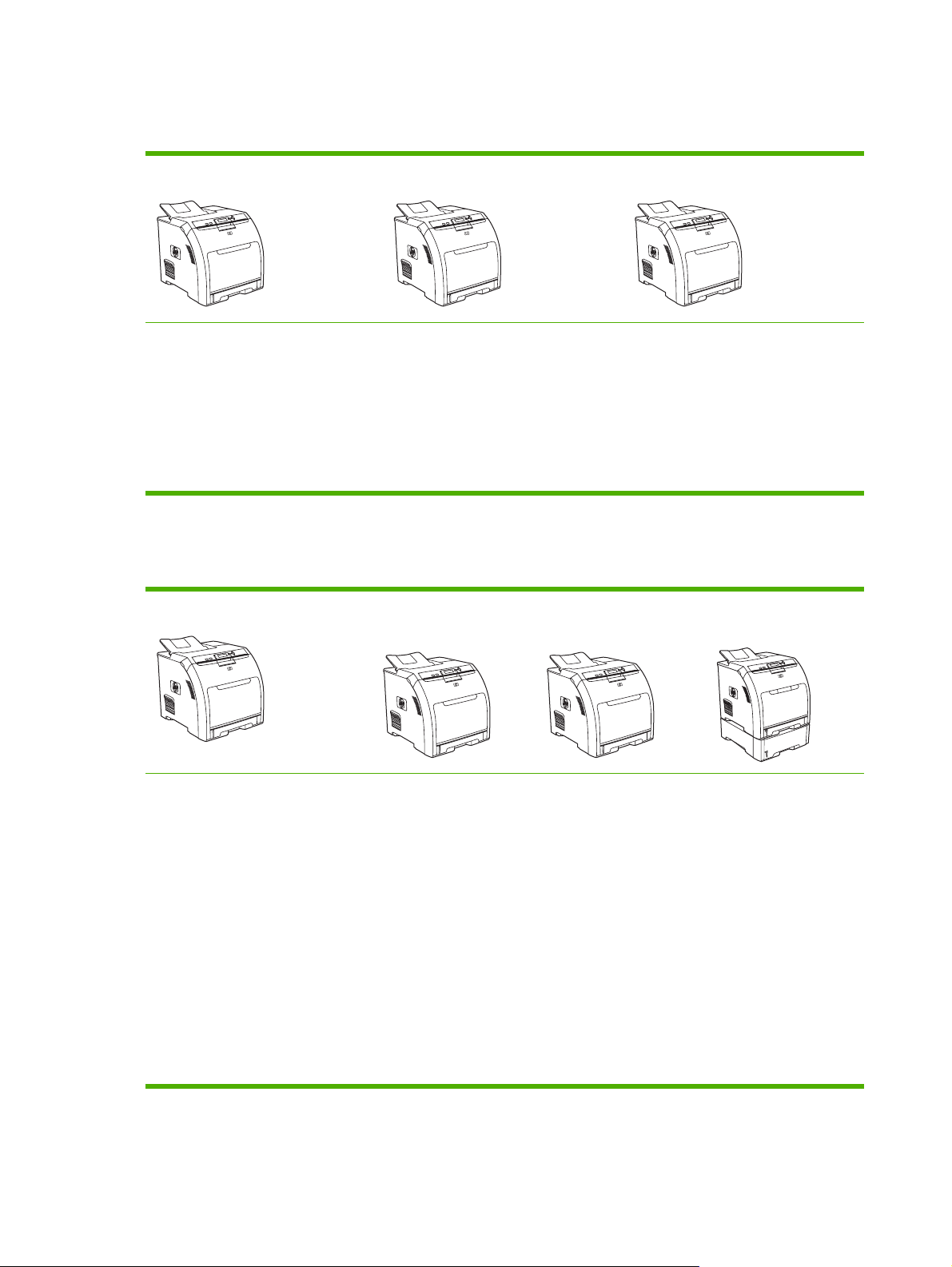
HP Color LaserJet 3600 Series printer
Table 1-3 HP Color LaserJet 3600 Series printer configurations
HP Color LaserJet 3600 printer HP Color LaserJet 3600n printer HP Color LaserJet 3600dn printer
17 ppm print speed
●
100-sheet multipurpose tray
●
(tray 1) and 250-sheet input tray
(tray 2)
Hi-Speed USB 2.0 port
●
64 MB RAM
●
The features of the HP Color LaserJet
3600 printer, plus:
HP Jetdirect value-featured
●
embedded print server to connect
to 10Base-T/100Base-TX networks
64 MB RAM
●
HP Color LaserJet 3800 Series printer
Table 1-4 HP Color LaserJet 3800 Series printer configurations
HP Color LaserJet 3800 printer HP Color LaserJet
3800n printer
22 ppm (letter-size) or 21 ppm
●
(A4) print speed
100-sheet multipurpose tray
●
(tray 1) and 250-sheet input
tray (tray 2)
The features of the
HP Color LaserJet 3800
printer, plus:
64 MB RAM (160
●
total)
The features of the HP Color LaserJet
3600 printer, plus:
64 MB RAM (128 total)
●
Automatic 2-sided (duplex) printing
●
HP Jetdirect value-featured
●
embedded print server to connect
to 10Base-T/100Base-TX networks
HP Color LaserJet
3800dn printer
The features of the
HP Color LaserJet 3800
printer, plus:
192 MB RAM (288
●
total)
HP Color LaserJet
3800dtn printer
The features of the
HP Color LaserJet 3800
printer, plus:
192 MB RAM (288
●
total)
Hi-Speed USB 2.0 port and EIO
●
slot
96 MB RAM
●
HP Jetdirect full-
●
featured embedded
print server to
connect to 10BaseT/100Base-TX
networks
Automatic 2-sided
●
(duplex) printing
HP Jetdirect full-
●
featured embedded
print server to
connect to 10BaseT/100Base-TX
networks
Automatic 2-sided
●
(duplex) printing
HP Jetdirect full-
●
featured embedded
print server to
connect to 10BaseT/100Base-TX
networks
500-sheet input tray
●
(tray 3)
4 Chapter 1 Product information ENWW
Page 17
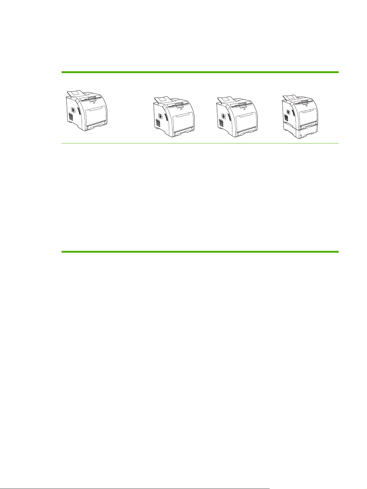
HP Color LaserJet CP3505 Series printer
The HP Color LaserJet CP3505 is available in the configurations described below.
Table 1-5 HP Color LaserJet CP3505 configurations
HP Color LaserJet CP3505 HP Color LaserJet
22 ppm (letter-size) or 21 ppm
●
(A4) print speed
100-sheet multipurpose tray
●
(tray 1) and 250-sheet input
tray (tray 2)
Hi-Speed USB 2.0 port and EIO
●
slot
256 megabytes (MB) of random
●
access memory (RAM)
CP3505n
HP Color LaserJet
CP3505, plus:
256 MB RAM
●
HP Jetdirect full-
●
featured embedded
print server to
connect to 10BaseT/100Base-TX
networks
HP Color LaserJet
CP3505dn
HP Color LaserJet
CP3505, plus:
384 MB RAM
●
Automatic 2-sided
●
(duplex) printing
HP Jetdirect full-
●
featured embedded
print server to
connect to 10BaseT/100Base-TX
networks
HP Color LaserJet
CP3505x
HP Color LaserJet
CP3505, plus:
384 MB RAM
●
Automatic 2-sided
●
(duplex) printing
HP Jetdirect full-
●
featured embedded
print server to
connect to 10BaseT/100Base-TX
networks
● 500-sheet input tray
(tray 3).
ENWW Printers at a glance 5
Page 18

Features at a glance
Table 1-6 Features
Feature HP Color LaserJet 3000 Series
Performance
User interface ● Graphic display
Printer drivers
printer
●
533 MHz processor
Control-panel help
●
HP Easy Printer Care Software
●
(a Windows
based status and
troubleshooting tool)
Windows and Macintosh printer
●
drivers
Embedded Web server to gain
●
access to support and to order
supplies (administrator tool for
network-connected models only)
HP formatter
●
HP PCL 5c
●
HP PCL 6
●
●
PostScript
®
- or Macintosh-
®
3 emulation
HP Color LaserJet 3600 Series
printer
360 MHz processor
●
● Graphic display
Control-panel help
●
HP Easy Printer Care Software
●
(a Windows- or Macintoshbased status and
troubleshooting tool)
Windows and Macintosh printer
●
drivers
Embedded Web server to
●
configure network settings only
(administrator tool for networkconnected models only)
Host formatter
●
HP JetReady 4.2
HP Color LaserJet 3800 Series
printer and HP Color LaserJet
CP3505 Series printer
533 MHz processor
●
● Graphic display
Control-panel help
●
HP Easy Printer Care Software
●
(a Windows- or Macintoshbased status and
troubleshooting tool)
Windows and Macintosh printer
●
drivers
Embedded Web server to gain
●
access to support and to order
supplies (administrator tool for
network-connected models only)
HP formatter
●
HP PCL 5c
●
HP PCL 6
●
PostScript 3 emulation
●
Job storage
Fonts
Expandability
Fonts, forms, and other macros
●
Job retention
●
80 internal fonts available for
●
both PCL and PostScript 3
emulation
80 printer-matching screen
●
fonts in TrueType format
available with the software
solution
Optional 500-sheet input tray
●
(tray 3) (standard on the
HP Color LaserJet 3000dtn
printer)
Dual inline memory modules
●
(DIMMs)
None
None
Optional 500-sheet input tray
●
(tray 3)
Fonts, forms, and other macros
●
Job retention
●
80 internal fonts available for
●
both PCL and PostScript 3
emulation
80 printer-matching screen
●
fonts in TrueType format
available with the software
solution
Optional 500-sheet input tray
●
(tray 3) (standard on the
HP Color LaserJet 3800dtn and
CP3505 printers)
DIMMs
●
6 Chapter 1 Product information ENWW
Page 19

Table 1-6 Features (continued)
Feature HP Color LaserJet 3000 Series
printer
Connectivity
Environmental
features
Hi-Speed USB 2.0 cable
●
interface
HP Jetdirect full-featured
●
embedded print server
(standard on the HP Color
LaserJet 3000n, 3000dn, and
3000dtn printers)
HP Web Jetadmin software
●
(standard on the HP Color
LaserJet 3000n, 3000dn, and
3000dtn printers)
Enhanced input/output (EIO) slot
●
Sleep-mode setting
●
High content of recyclable components and materials
●
●
ENERGY STAR
®
qualified models; see http://www.hp.com/go/energystar
HP Color LaserJet 3600 Series
printer
Hi-Speed USB 2.0 cable
●
interface
HP Jetdirect value-featured
●
embedded print server
(standard on the HP Color
LaserJet 3600n and 3600dn
printers)
HP Web Jetadmin software
●
(standard on the HP Color
LaserJet 3600n and 3600dn
printers)
HP Color LaserJet 3800 Series
printer and HP Color LaserJet
CP3505 Series printer
Hi-Speed USB 2.0 cable
●
interface
HP Jetdirect full-featured
●
embedded print server
(standard on the HP Color
LaserJet 3800n, 3800dn, and
3800dtn printers and the HP
Color LaserJet CP3505n,
CP3505dn, and CP3505x
printers)
HP Web Jetadmin software
●
(standard on the HP Color
LaserJet 3800n, 3800dn, and
3800dtn printers and the HP
Color LaserJet CP3505n,
CP3505dn, and CP3505x
printers)
Enhanced input/output (EIO) slot
●
Paper handling
Supplies
Accessibility
Input
●
Tray 1 (multipurpose tray): A multipurpose tray for paper, transparencies, labels, and envelopes. Holds up
●
to 100 sheets of paper or 20 envelopes.
● Tray 2: 250-sheet tray that automatically detects standard paper sizes up to legal and allows printing on
custom-size paper.
Tray 3: 500-sheet tray that automatically detect standard paper sizes up to legal and allows printing on
●
custom-size paper.
Output
●
Face-up output bin
●
Face-down output bin
●
Supplies status page contains information about toner level, page count, and estimated pages remaining
●
No-shake cartridge design
●
Printer checks for authentic HP print cartridges at cartridge installation
●
●
Internet-enabled supply-ordering capabilities (using HP Easy Printer Care Software)
The online user guide is compatible with text screen-readers.
●
Print cartridges can be installed and removed by using one hand.
●
All doors and covers can be opened by using one hand.
●
●
Media can be loaded in tray 1 by using one hand.
ENWW Features at a glance 7
Page 20
Walkaround
1
2
3
4
5
6
7
8
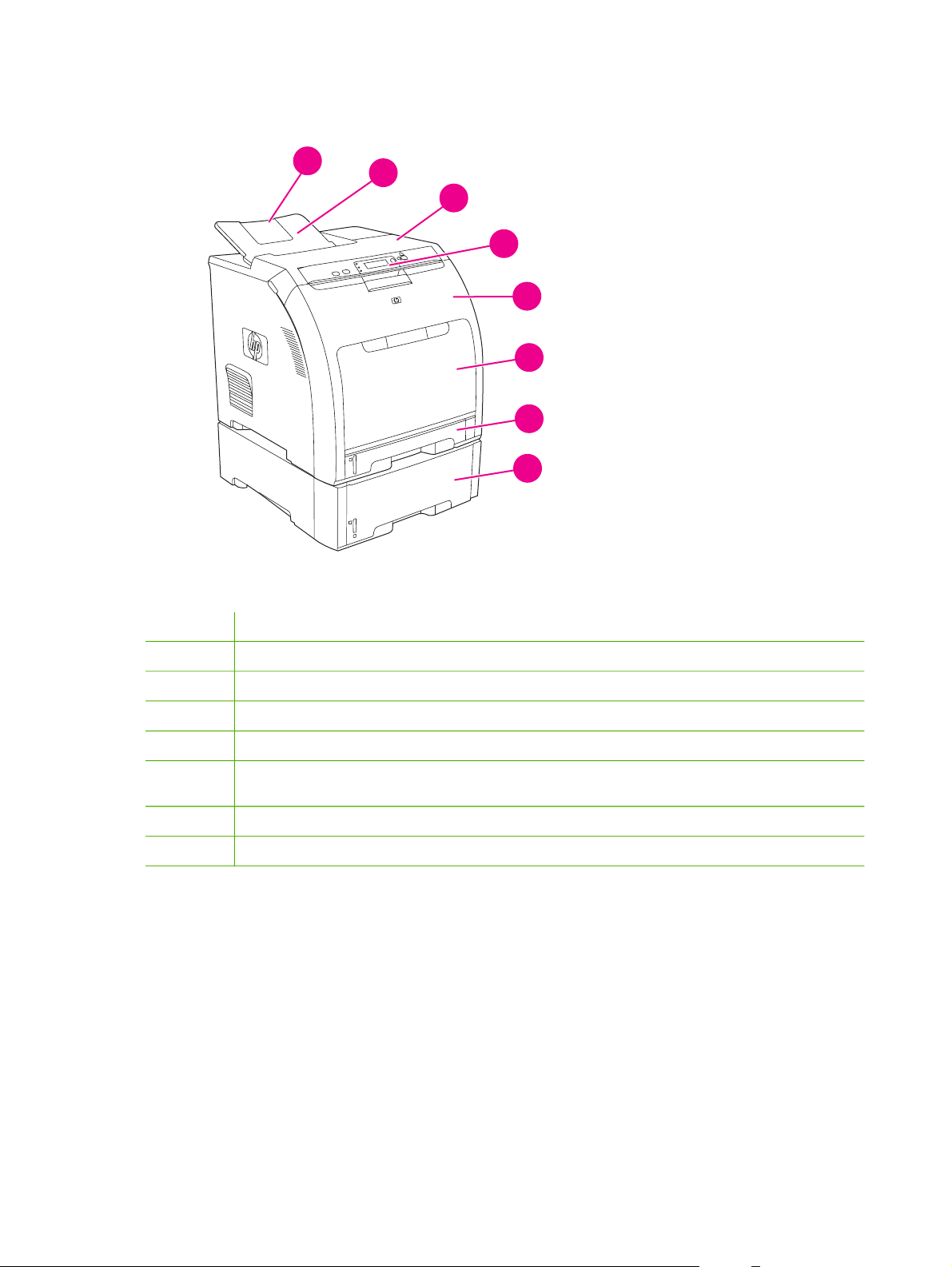
Figure 1-1 Front view (shown with optional 500-sheet paper feeder)
1 Output bin extender
2
3
4
5
6
7
8 Tray 3 cassette (optional; holds 500 sheets of standard paper)
Output bin
Top cover (This part is called the upper cover in this service manual.)
Printer control panel
Front door (This part is called the front cover in this service manual.)
Tray 1 (holds 100 sheets of standard paper) (This part is called the multipurpose-tray assembly in this
service manual.)
Tray 2 cassette (holds 250 sheets of standard paper)
8 Chapter 1 Product information ENWW
Page 21
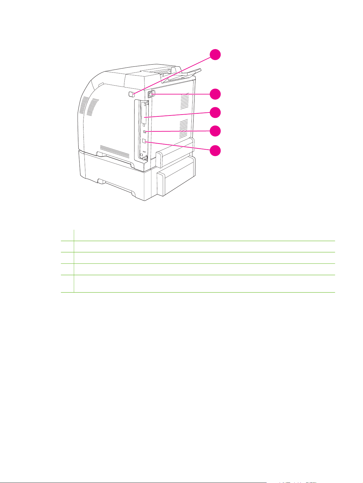
Figure 1-2 Back and side view
1
2
3
4
5
1
On/off switch
2 Power connection
3
EIO slot (available on the HP Color LaserJet 3000, 3800, and CP3505 Series printers)
4
Hi-Speed USB 2.0 port
5 Network port (available on the HP Color LaserJet 3000n, 3000dn, 3000dtn, 3600n, 3600dn, 3800n, 3800dn, and
3800dtn, CP3505n, CP3505dn, and CP3505x printers)
ENWW Walkaround 9
Page 22
Control-panel overview
The control panel provides controls for printer functions and shows messages about the printer, print
jobs, and supplies status.
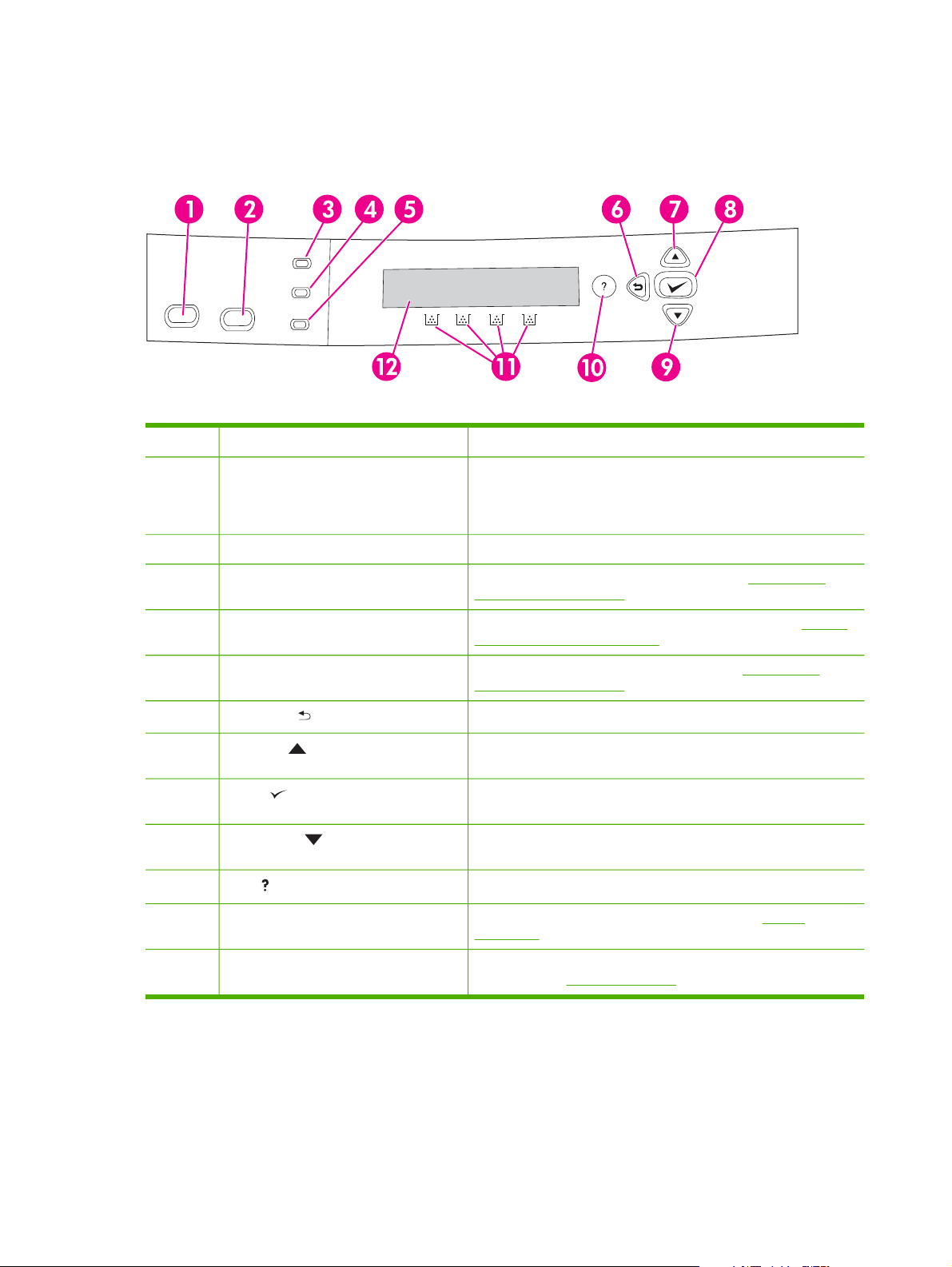
Figure 1-3 Control panel buttons and lights
Number Button or light Function
1 Stop button Halts the current job, presents a choice to resume or cancel the
2 Menu button Opens and closes menus.
current print job, clears media from the printer, and clears any
continuable errors that are associated with the halted job. If the
printer is not printing a job, pressing Stop pauses the printer.
3 Ready light Indicates that the printer is online or offline. See Control-panel
4 Data light Indicates whether or not the printer is receiving data. See Control-
5 Attention light Indicates that a critical error has occurred. See Control-panel
6
7
8
9
10
11 Supplies gauge Shows the print cartridge-consumption levels. See Display
12 Display Shows status information, menus, help information, and error
Back arrow ( ) button
Up arrow ( ) button
Select ( ) button
Down arrow ( ) button
Help ( ) button
indicator lights on page 11.
panel indicator lights on page 11.
indicator lights on page 11.
Navigates backward in nested menus.
Navigates menus and text, and increases the values of numerical
items in the display.
Makes selections, resumes printing after continuable errors, and
overrides a non-HP print cartridge.
Navigates menus and text, and decreases the values of numerical
items in the display.
Provides detailed information about printer messages or menus.
on page 11.
messages. See
Display on page 11.
The printer communicates through the display and the lights on the control panel. The display shows
status information, menus, help information, and error messages. The Ready, Data, and Attention
lights provide at-a-glance information about the printer state.
10 Chapter 1 Product information ENWW
Page 23
You can perform most routine printing tasks from the computer through the printer driver or any
software program. Use the control panel to access printer features that the printer driver or software
program do not support. Any changes that you make from the computer override the printer controlpanel settings. For information about using the printer driver, see
Control-panel indicator lights
Indicator On Off Flashing
Printer software on page 13.
Display
Ready
(green)
Data
(green)
Attention
(amber)
The printer is online (can
accept and process data).
The processed data is
present in the printer, but
more data is needed to
complete the job, or the job
is paused or waiting for
errors to be cleared.
A critical error has occurred.
The printer requires attention.
The printer is offline
(paused), or is turned off.
The printer is not processing
or receiving data.
No conditions exist that
require attention.
The printer is attempting to
stop printing and go offline.
This usually results from a
user's request to pause the
current job.
The printer is processing
and receiving data.
An error has occurred. The
printer requires attention.
The printer display gives you complete, timely information about the printer and print jobs. Graphics
illustrate levels of supplies. Menus provide access to printer functions and detailed information.
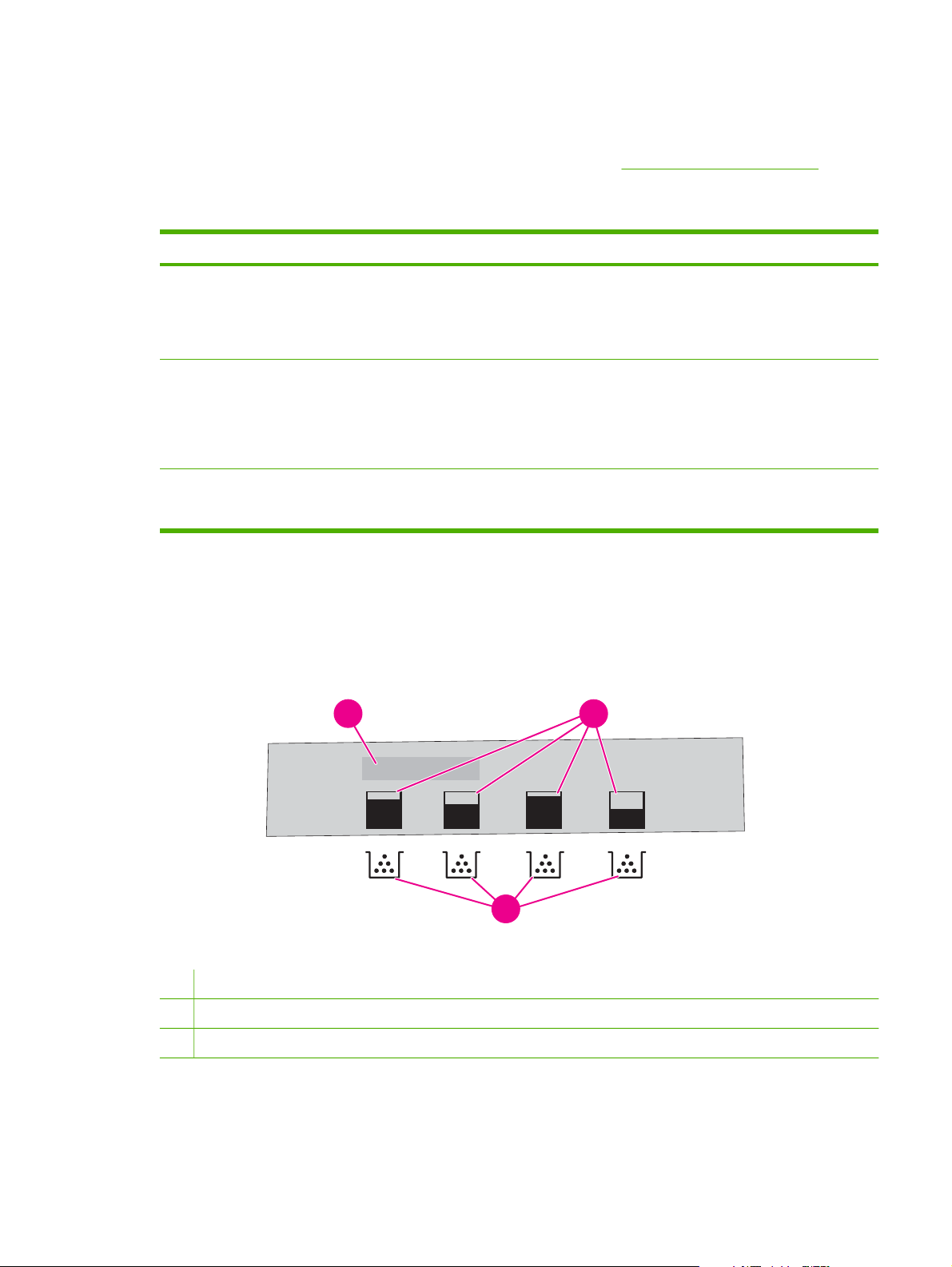
The top-level screen on the display has two areas: message/prompt and supplies gauge.
1
2
3
Figure 1-4 Printer display
1 Message/prompt area
2 Supplies gauge
3 Print cartridge colors from left to right: black, yellow, cyan, and magenta
The message and prompt areas of the display alert you to the state of the printer and tell you how to
respond.
ENWW Control-panel overview 11
Page 24

The supplies gauge shows the consumption levels of print cartridges (black, cyan, magenta, and
yellow). When a non-HP print cartridge is installed, a ? might appear instead of the consumption
level. The supplies gauge appears whenever the printer shows the Ready state, and whenever the
printer shows a warning or error message concerning a cartridge.
12 Chapter 1 Product information ENWW
Page 25

Printer software
The printing-system software is included with the printer. See the getting started guide for installation
instructions.
The printing system includes software for end users and network administrators, and printer drivers
for access to the printer features and communication with the computer.
For a list of printer drivers and updated HP printer software, go to the following Web sites:
HP Color LaserJet 3000 Series printer, go to
●
HP Color LaserJet 3600 Series printer, go to
●
HP Color LaserJet 3800 Series printer, go to
●
HP Color LaserJet CP3505 Series printer, go to
●
http://www.hp.com/go/clj3000_software
http://www.hp.com/go/clj3600_software
http://www.hp.com/go/clj3800_software
http://www.hp.com/go/cljcp3505_software
HP Color LaserJet 3000 Series printer, HP Color LaserJet 3800 Series
printer, and HP Color LaserJet CP3505 Series printer drivers
The HP Color LaserJet 3000, 3800, and CP3505 Series printers use the PCL 5c, PCL 6, and
PostScript 3 emulation PDL drivers.
NOTE: For Windows 2000, Windows XP, and Windows Server 2003, the HP Color LaserJet
3000 and 3800 Series printers include a monochrome PCL 6 driver that can be installed for
users who will be printing only black-and-white print jobs.
ENWW Printer software 13
Page 26

Table 1-7 Available printer drivers
Operating system
Windows 98, Windows Me (HP Color
LaserJet 3000 and 3800 only)
Windows 2000
1
3
PCL 5c
PCL 6
2
PS 3 emulation
Windows XP (32-bit)
Windows Server 2003 (32-bit)
Windows Server 2003 (64-bit)
Windows Vista (32–bit)
Windows Vista (64–bit)
Mac OS V9.2.2 and later, and
OS X V10.2 and later (HP CLJ 3000
and 3800)
Mac OS X V10.2.8 and later (HP CLJ
CP3505)
1
Not all printer features are available from all drivers or operating systems.
2
The HP Color LaserJet 3000 and 3800 Series printers include both a monochrome and color PCL 6 driver for
Windows 2000, Windows XP, and Windows Server 2003 users.
3
For Windows 2000 and Windows XP (32-bit and 64-bit), download the PCL 5 driver from http://www.hp.com/go/
clj3000_software or http://www.hp.com/go/clj3800_software.
4
For Windows XP (64-bit), download the PCL 6 driver from http://www.hp.com/go/clj3000_software or http://www.hp.com/go/
clj3800_software.
4
HP Color LaserJet 3600 Series printer drivers
The HP Color LaserJet 3600 Series printer uses the HP JetReady 4.2 Page Description Language
(PDL), a host-based printer language. HP JetReady 4.2 uses the combined power of the computer
and the printer to render the printed page in a Windows or Macintosh system environment.
HP JetReady 4.2 transfers the prerendered pages from the host computer to the printer and
communicates instructions to the printer about how to convert the pages to data that can be printed.
The HP JetReady 4.2 PDL driver is available on the installation CD for the following operating
systems:
Windows 98, Windows Millennium Edition (Me)
●
Windows 2000
●
Windows XP (32-bit and 64-bit)
●
Windows Server 2003 (32-bit and 64-bit)
●
Macintosh OS X V10.2 and later
●
14 Chapter 1 Product information ENWW
Page 27

NOTE: Not all printer features are available from all drivers or operating systems.
If your system did not automatically check the Internet for the latest drivers during software
installation, download them from
Additional drivers
The following drivers are not included on the CD, but are available from http://www.hp.com/go/
clj3000_software or http://www.hp.com/go/clj3800_software. These drivers are for the HP Color
LaserJet 3000 and 3800 Series printers only.
http://www.hp.com/go/clj3600_software.
●
●
●
®
model scripts
UNIX
Linux drivers
OS/2 PS and PCL printer driver
NOTE: The OS/2 drivers are available from IBM and are packaged with OS/2. They are not
available for Traditional Chinese, Simplified Chinese, Korean, and Japanese languages.
Software for networks
For a summary of available HP network installation and configuration software solutions, see the HP
Jetdirect Print Server Administrators Guide. You can find this guide on the printer CD.
HP Web Jetadmin
HP Web Jetadmin is a browser-based management tool for HP Jetdirect-connected printers within
your intranet, and it should be installed only on the network administrator's computer.
To download a current version of HP Web Jetadmin and for the latest list of supported host systems,
http://www.hp.com/go/webjetadmin.
visit
When HP Web Jetadmin is installed on a host server, any client can gain access to it by using a
supported Web browser (such as Microsoft® Internet Explorer 4.x or Netscape Navigator 4.x or later)
by navigating to the HP Web Jetadmin host.
UNIX
For HP-UX and Solaris networks, go to http://www.hp.com/support/net_printing to download the
HP Jetdirect printer installer for UNIX.
NOTE: The HP Color LaserJet 3600 Series printer does not support UNIX printing.
However, if UNIX is running CUPS and has the HPLIP or HPIJS system on it, the CLJ3600
can be used to print. See
additional information.
http://www.linuxprinting.org and look up the HP CLJ3600 for
Linux
For information, go to http://www.hp.com/go/linuxprinting.
ENWW Printer software 15
Page 28

Utilities
The HP Color LaserJet 3000, 3600, 3800, and CP3505 Series printers are equipped with several
utilities that make it easy to monitor and manage the printer on a network.
HP Easy Printer Care Software
The HP Easy Printer Care Software is a software program that you can use for the following tasks:
Checking the printer status
●
Checking the supplies status
●
Setting up alerts
●
Viewing printer documentation
●
Gaining access to troubleshooting and maintenance tools
●
HP Printer Utility for Mac
●
You can view the HP Easy Printer Care Software when the printer is directly connected to your
computer or when it is connected to a network. Perform a complete software installation in order to
use the HP Easy Printer Care Software.
Embedded Web server
NOTE: The HP Color LaserJet 3600 Series printer embedded Web server provides network
configuration and status information only.
The printers are equipped with an embedded Web server, which provides access to information
about printer and network activities. This information appears in a Web browser, such as Microsoft
Internet Explorer or Netscape Navigator.
The embedded Web server resides on the printer. It is not loaded on a network server.
Using the embedded Web server on page 35 for more information.
See
Other components and utilities
Several software programs are available for Windows and Macintosh users.
Windows Macintosh OS
Software installer automates the printing system
●
installation
Online Web registration
●
PostScript Printer Description files (PPDs) for use with
●
the Apple PostScript drivers that come with the Mac OS
Use the HP Printer Utility to change printer settings,
●
view the current status, and receive printer event
updates from a Macintosh computers. This utility is
supported for Mac OS X V10.2 and V10.3.
16 Chapter 1 Product information ENWW
Page 29
Print-media specifications
For optimum results, HP recommends using HP media that is designed for HP Color LaserJet
printers. Use media with a weight between 75 g/m
printer supports media with weights between 60 g/m
heavier media could impact the paper-jam rate and the optimal print-quality performance.
Always use the correct media-type setting in the printer driver, and configure the trays for the correct
media type. HP recommends testing any paper before buying it in large quantities.
Supported paper and print media sizes
This product supports a number of paper sizes, and it adapts to various media.
NOTE: To obtain best print results, select the appropriate paper size and type in your print
driver before printing.
Table 1-8 Supported paper and print media sizes
Size Dimensions Tray 1 Tray 2 Optional tray 3
Letter 216 x 279 mm (8.5 x 11 inches)
Legal 216 x 356 mm (8.5 x 14 inches)
A4 210 x 297 mm (8.27 x 11.69 inches)
2
to 120 g/m2 (20 to 32 lb bond). Although the
2
to 220 g/m2 (16 to 58 lb bond), using lighter or
Executive 184 x 267 mm (7.24 x 10.51 inches)
A3 297 x 420 mm (11.69 x 16.54 inches)
A5 148 x 210 mm (5.83 x 8.27 inches)
A6 105 x 148 mm (4.13 x 5.83 inches)
B5 (JIS) 182 x 257 mm (7.17 x 10.12 inches)
B5 (ISO) 176 x 250 mm (6.93 x 9.84 inches)
B6 (ISO) 125 x 176 mm (4.92 x 6.93 inches)
16k 197 x 273 mm (7.75 x 10.75 inches)
16k 184 x 260 mm (7.24 x 10.23 inches)
16k 195 x 270 mm (7.68 x 10.63 inches)
8.5 x 13
(custom)
Custom (148 - 216) x (210 - 356) mm ((5.83 - 8.5) x
216 x 330 mm (8.5 x 13 inches)
(8.27 - 14) inches)
ENWW Print-media specifications 17
Page 30

Table 1-9 Supported envelopes and postcards
Size Dimensions Tray 1 Tray 2 Optional tray 3
Envelope #10 105 x 241 mm (4.13 x 9.49 inches)
Envelope DL 110 x 220 mm (4.33 x 8.66 inches)
Envelope C5 162 x 229 mm (6.93 x 9.84 inches)
Envelope B5 176 x 250 mm (6.7 x 9.8 inches)
Envelope
98 x 191 mm (3.9 x 7.5 inches)
Monarch
Media type and tray loading
Minimum media dimensions are 148 x 210 mm (5.83 x 8.27 inches).
Maximum media dimensions are 216 x 356 mm (8.5 x 14 inches).
Table 1-10 Tray 1 media information
Media type Media specifications Media quantity Driver settings Paper orientation
Paper and cardstock,
standard sizes
Envelopes
Labels Maximum 0.23 mm
Range:
2
60 g/m
(16 lb) bond
to 163 g/m
bond
Less than 60 g/m2 (16
lb) bond to 90 g/m
(24 lb) bond
(0.009 in.) thick
2
(43 lb)
Maximum stack
Plain or unspecified N/A
height: 10 mm (0.6
inch)
Equivalent to 100
sheets of 75 g/m
2
(20
lb) bond.
Up to 10 envelopes Envelope Short edge leading,
2
flap on right side
facing up
Maximum stack
height: 10 mm (0.6
Labels Side to be printed on
facing down
inch)
Transparencies Minimum 0.13 mm
(0.005 in.) thick
Maximum stack
height: 10 mm (0.6
Transparencies Side to be printed on
facing down
inch)
Heavy 0.13 mm (0.005 in.)
thick
Glossy Range:
2
75 g/m
(20 lb) bond
to 220 g/m
2
(48 lb)
Maximum stack
height: 10 mm (0.6 in.)
Maximum stack
height: 10 mm (0.6 in.)
Light glossy, glossy,
or heavy glossy
Light glossy, glossy,
or heavy glossy
Side to be printed on
facing down
Side to be printed on
facing down
bond
Cardstock Range:
163 g/m
to 220 g/m
2
(43 lb) bond
2
(48 lb)
60 sheets Cardstock Side to be printed on
facing down
cover
18 Chapter 1 Product information ENWW
Page 31

Table 1-11 Tray 2, tray 3, and tray 4 media information
Media type Media
specifications
Paper and
cardstock,
standard sizes
Range:
60 g/m
2
(16 lb)
bond to 120 g/m
(32 lb) bond
Labels Maximum 0.13
mm (0.005 in.)
thick
Transparencies Minimum 0.13
mm (0.005 in.)
thick
Heavy 0.13 mm (0.005
in.) thick
Glossy Range:
2
106 g/m
(28 lb)
bond to 120 g/m
(32 lb) bond
Media quantity Driver settings Paper orientation Output
Equivalent to 250
sheets (tray 2) or
500 sheets (tray
2
3) of 75 g/m
2
(20
Plain or
unspecified
N/A
lb) bond.
Maximum stack
height: 50 sheets
Labels Side to be printed
on facing up
(tray 2), or 100
sheets (tray 3)
Maximum stack
height: 50 sheets
Transparencies Side to be printed
on facing up
(tray 2), or 100
sheets (tray 3)
Maximum stack
height: 100
sheets (tray 2), or
Light glossy,
glossy, or heavy
glossy
Side to be printed
on facing up
200 sheets (tray 3)
Maximum stack
height: 100
sheets (tray 2), or
2
200 sheets (tray 3)
Light glossy,
glossy, or heavy
glossy
Side to be printed
on facing up
ENWW Print-media specifications 19
Page 32

20 Chapter 1 Product information ENWW
Page 33

2 Installation and configuration
What is in the box
●
Site requirements
●
Connecting to a network or a computer
●
Printer memory
●
ENWW 21
Page 34
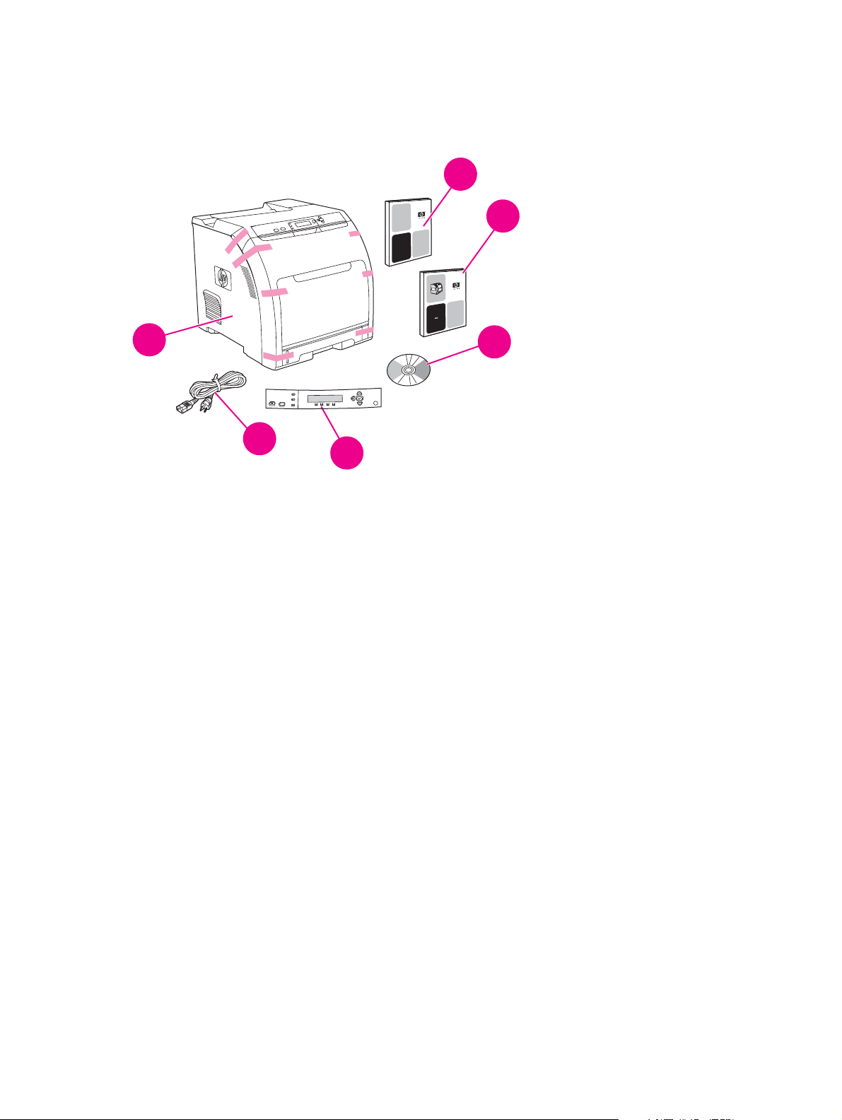
What is in the box
The following items come in the box with the printer.
1
2
4
Ready
Data
Stop
Menu
Attention
6
5
Figure 2-1 What is in the shipping box
1. Getting started guide
2. Warranty booklet
3. User guide on CD
4. Printer
5. Control-panel overlays (optional)
6. Power cord
3
?
22 Chapter 2 Installation and configuration ENWW
Page 35

Site requirements
Select a sturdy, well-ventilated, dust-free area that is away from direct sunlight to position the printer.
Allow enough space around the printer to open the doors and trays.
Physical specifications
Table 2-1 Physical dimensions for the HP Color LaserJet 3000/3600/3800/CP3505 Series printers
Product Height Depth Width
Base model 400 mm (15.7 in) 450 mm (17.7 in) 400 mm (15.7 in)
Weight
20.3 kg
(44.8 lbs)
1
Base model plus duplexer 423 mm (16.7 in) 450 mm (17.7 in) 400 mm (15.7 in)
Base model plus optional tray 3 540 mm (21.3 in) 450 mm (17.7 in) 400 mm (15.7 in) 25.4 kg (56 lbs)
Base model plus duplexer and optional
tray 3
1
Printer weight does not include print cartridges.
563 mm (22.2 in) 450 mm (17.7 in) 400 mm (15.7 in) 26.6 kg
21.5 kg
(47.4 lbs)
(58.6 lbs)
ENWW Site requirements 23
Page 36

Connecting to a network or a computer
To connect to a network
1. Connect the network cable to the printer.
2. Find the IP address. On the control panel, press Menu. Select INFORMATION, and then select
PRINT CONFIGURATION. The IP address is on the embedded Jetdirect page, under “TCP/IP”.
NOTE: You might need to assign an IP address depending on the type of network that
is installed.
3. Configure an IP address (if necessary). On the control panel, press Menu. Select CONFIGURE
DEVICE, select I/O, and then select EMBEDDED JETDIRECT. Select TCP/IP, select CONFIG
METHOD, select MANUAL, and then select MANUAL SETTINGS. Use the control-panel
buttons to specify the IP address.
4. Prepare for software installation. Quit all of the programs (including terminate-and-stay resident
[TSR], antivirus, and firewall programs) on the print server or on each computer that will use the
printer.
5. Install the software. Insert the CD that came with the printer, and then click Install Printer on the
welcome screen. (If the welcome screen does not appear, click Start, and then click Run. Type
X:SETUP, replace X with the CD-ROM drive letter, and then click OK.)
6. Follow the onscreen instructions. When prompted, select Wired Networking. The installer shows
available printers. Select the appropriate IP address.
7. On the Installation Type screen select Full Installation to install the most common drivers and
software, select Basic Installation to install the minimum set of drivers and software
(recommended), or select Custom Installation.
NOTE: See the HP Jetdirect Print Server Administrators Guide for more information. You
can find this guide on the printer CD.
To use Windows with a direct connection (USB)
1. Install the software from the CD before connecting the cable to the printer.
2. On the welcome screen, click Install Printer. The Setup Wizard appears.
NOTE: If the welcome screen does not appear, click Start, and then click Run. Type
X:SETUP, replace X with the CD-ROM drive letter, and then click OK.
3. Follow the onscreen instructions. When prompted, connect a USB cable between the printer
and the computer.
NOTE: HP does not recommend using USB hubs. Use a USB cable that is no longer
than 2 meters (6.5 feet).
4. Click Finish. If prompted, restart the computer.
5. Test the software installation. Print a page from any program to make sure that the software is
correctly installed.
24 Chapter 2 Installation and configuration ENWW
Page 37

NOTE: If the installation failed, reinstall the software.
NOTE: If the New Hardware Found message appears, insert the CD, follow the
onscreen instructions, and accept the default selections.
To connect to a Macintosh computer
NOTE: The HP Color LaserJet CP3505 supports Macintosh OS X V10.28, V10.3, V10.4 or
later. For Macintosh OS X V10.4, PPC and Intel core processor Macintosh are supported.
1. Connect a USB cable between the printer and the computer.
NOTE: HP does not recommend using USB hubs. Use a USB cable that is no longer
than 2 meters (6.5 feet).
2. Place the CD in the CD-ROM drive. For OS V9.1 to V9.2.x, go to step 3. For OS X, go to step 7.
3. Run the Installer and complete a custom install. Select all options, including USB Components
(Classic). When prompted, restart the computer.
4. Run the Apple Desktop Printer Utility from HD/Applications/Utilities. Double-click HP Printer
(USB), and then click OK. Next to the USB Printer Selection, click Change.
5. Select the printer, and then click OK. Next to Postscript Printer Description (PPD) File, click
Auto Setup, and then click Create. Save the printer setup.
6. On the desktop, highlight the printer. Click the Printing menu, and then click Set Default
Printer. Go to step 10.
7. Run the Installer and complete an easy install.
NOTE: If OS X and OS V9.1 (Classic) to V9.2.x (Classic) are installed on the same
computer, the installer shows both the Classic and the OS X installation options.
8. From HD/Applications/Utilities/Print Center, start the Print Center. If the printer appears in the
Printer List, delete the printer. Click Add. On the next page, click the drop-down menu, and
then select USB.
9. From the Printer Model drop-down list, select HP. Under Model Name, select the printer, and
then click Add.
10. Test the software installation. Print a page from any program to make sure that the software is
correctly installed.
NOTE: If the installation failed, reinstall the software.
ENWW Connecting to a network or a computer 25
Page 38

Printer memory
NOTE: This information applies to the HP Color LaserJet 3000, 3800, and CP3505 Series
printers only.
The HP Color LaserJet 3000, 3800, and CP3505 Series printers have one DIMM slot.
More printer memory DIMMs are available in 128, 256, and 512 MB increments.
●
Other DIMM-based printer languages and printer options are available.
●
NOTE: Single in-line memory modules (SIMMs) that are used on previous HP LaserJet
printers are not compatible with these printers.
You might want to add more memory to the printer if you often print complex graphics or PostScript
documents, if you use many downloaded fonts, or if a Jetdirect EIO print server will be installed for
network printing capabilities. Additional memory also allows the printer to print multiple collated
copies at the maximum speed.
Before ordering additional memory, see how much memory is currently installed by printing a
configuration page. See
Installing memory DIMMs
You can install more memory for the printer, and you can also install a font DIMM to print characters
for languages such as Chinese or the Cyrillic alphabet.
Using printer information pages on page 40.
CAUTION: Static electricity can damage DIMMs. When handling DIMMs, either wear an
antistatic wrist strap or frequently touch the surface of the DIMM antistatic package and then
touch bare metal on the printer.
To install memory DIMMs
1. Turn the printer off, and then disconnect all power and interface cables.
26 Chapter 2 Installation and configuration ENWW
Page 39
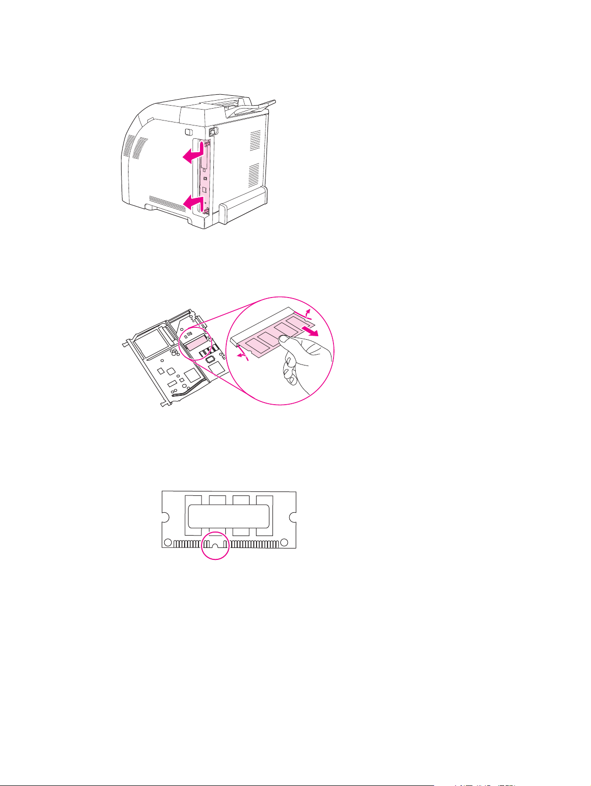
2. On the right side of the printer, gently pull the black tabs together, and then pull the formatter
assembly from the printer.
3. Place the formatter board on a clean, flat, grounded surface.
To replace a DIMM that is currently installed, spread the latches apart on each side of the DIMM
slot, lift the DIMM up at an angle, and pull it out.
4. Remove the new DIMM from the antistatic package, and then locate the alignment notch on the
bottom edge of the DIMM.
ENWW Printer memory 27
Page 40
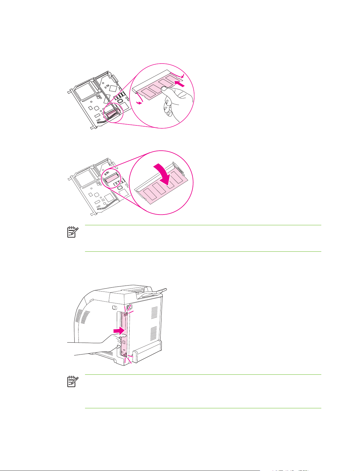
5. Holding the DIMM by the edges, align the notch on the DIMM with the bar in the DIMM slot at an
angle and firmly press the DIMM into the slot until it is fully seated. When installed correctly, the
metal contacts are not visible.
6. Push down on the DIMM until both latches engage the DIMM.
NOTE: If you have difficulty inserting the DIMM, make sure that the notch on the bottom
of the DIMM is aligned with the bar in the slot. If the DIMM still does not go in, make sure
that you are using the correct DIMM type.
7. Align the edge of the formatter board in the tracks at the top and bottom of the slot, and then
slide the board into the printer. Push the formatter firmly until you hear the formatter latches
click into place.
NOTE: After replacing the formatter, make sure that the control panel is functioning. If
the printer fans and motors are operating correctly but the control panel is not, turn the
power off, and then remove the formatter and reinstall it. You might have to repeat this
step several times to seat the formatter correctly.
28 Chapter 2 Installation and configuration ENWW
Page 41

8. Reconnect the power cable and USB or network cable, and then turn on the printer.
9. After installing a memory DIMM, see
Enabling memory
If you installed a memory DIMM, set the printer driver to recognize the newly added memory.
To enable memory for Windows
1. On the Start menu, point to Settings, and click Printers or Printers and Faxes.
2. Select this printer and select Properties.
3. On the Configure tab, click More.
4. In the Total Memory field, type or select the total amount of memory that is now installed.
5. Click OK.
6. Go to
Checking DIMM installation on page 29.
Checking DIMM installation
Check that the DIMMs are installed correctly and working.
To check DIMM installation
1. Turn the printer on. Check that the printer is in the Ready state after it has gone through the
startup sequence. If an error message appears, a DIMM might have been incorrectly installed.
Enabling memory on page 29.
2. Print a configuration page. See
3. Check the Installed Personalities and Options section on the configuration page and compare it
with the configuration page that you printed before the DIMM installation.
4. If the information on the configuration page has not changed, one of the following situations
exists:
The DIMM might not be installed correctly. Repeat the installation procedure.
-or-
The DIMM might be defective. Try a new DIMM.
Using printer information pages on page 40.
ENWW Printer memory 29
Page 42

30 Chapter 2 Installation and configuration ENWW
Page 43

3 Maintenance
Understanding approximate supplies-replacement intervals
●
Replacing supplies
●
Managing the print cartridge
●
Cleaning the printer
●
Calibrating the printer
●
Tools for troubleshooting
●
ENWW 31
Page 44

Understanding approximate supplies-replacement intervals
The following table lists the estimated replacement intervals for supplies and the control-panel
messages that prompt you to replace each item. Usage conditions and print patterns can cause
results to vary.
Item Printer message Page count
Black cartridges REPLACE BLACK
Color cartridges REPLACE <COLOR>
1
Approximate average A4-/letter-size page count based on 5% coverage of individual colors
CARTRIDGE
CARTRIDGE
(HP Color LaserJet
3000)
6,500 pages
3,500 pages
1
1
Page count
(HP Color LaserJet
3600)
6,000 pages
4,000 pages
1
1
Page count
(HP Color LaserJet
3800 and CP3505)
6,000 pages
6,000 pages
1
1
You can use the embedded Web server to order supplies. See Using the embedded Web server
on page 41.
32 Chapter 3 Maintenance ENWW
Page 45

Replacing supplies
When you use genuine HP supplies, the printer automatically notifies you when supplies are nearly
depleted. The notification to order supplies allows ample time to order new supplies before they need
to be replaced.
Locating supplies
Supplies are identified by their labeling and their blue plastic handles.
The following figure illustrates the location of the print cartridges.
Figure 3-1 Supply-item locations
1 Print cartridges
Supply replacement guidelines
To facilitate the replacement of supplies, keep the following guidelines in mind when setting up the
printer.
Allow sufficient space above and in the front of the printer for removing supplies.
●
Place the printer on a flat, sturdy surface.
●
For instructions about installing supplies, see the installation guides that came with each supply item,
or see more information at
http://www.hp.com/support/clj3800, or http://www.hp.com/support/cljcp3505. When you connect,
select Troubleshoot a Problem.
CAUTION: Hewlett-Packard Company recommends the use of genuine HP products in this
printer. Use of non-HP products might cause problems requiring service that is not covered by
the Hewlett-Packard extended warranty or service agreements.
http://www.hp.com/support/clj3000, http://www.hp.com/support/clj3600,
ENWW Replacing supplies 33
Page 46

Managing the print cartridge
This section provides information about HP print cartridges, including their life expectancies, how to
store them, and how to identify genuine HP supplies. Information also appears about non-HP print
cartridges.
HP print cartridges
When you use a genuine HP print cartridge, you can obtain several types of information:
Amount of toner remaining
●
Estimated number of pages remaining
●
Number of pages printed
●
Non-HP print cartridges
Hewlett-Packard Company cannot recommend use of non-HP print cartridges, either new or
remanufactured. Because they are not HP products, HP cannot influence their design or control their
quality. Service or repair that is required as a result of using a non-HP print cartridge will not be
covered under the printer warranty.
When you use a non-HP print cartridge, certain features, such as remaining toner-volume data,
might not be available.
Using genuine HP supplies ensures the availability of all HP printing features.
Print-cartridge authentication
A message appears on the printer control-panel display if you insert a print cartridge that is not a
genuine HP print cartridge. If you believe that you purchased a genuine HP supply, go to
http://www.hp.com/go/anticounterfeit.
Print-cartridge storage
Do not remove the print cartridge from its package until you are ready to use it.
Always store the print cartridge in the correct environment. The storage temperature should be
between -20°C and 40°C (-4°F to 104°F). The relative humidity should be between 10% and 90%.
CAUTION: To prevent damage to the print cartridge, do not expose it to light for more than a
few minutes.
Print-cartridge life expectancy
The life of the print cartridge depends on the amount of toner that print jobs require and the length of
life for the components inside the cartridge. The page-yield specification that HP provides is a
general guideline. Actual yield can vary according to usage conditions.
At any time, you can verify life expectancy by checking the supply level.
34 Chapter 3 Maintenance ENWW
Page 47

Checking the supply level
You can check the toner-supply level by using the control panel, the embedded Web server, or
HP Web Jetadmin.
Using the control panel
1. Press Menu to open the MENUS.
2.
3.
Press
Press
to highlight INFORMATION.
to highlight PRINT SUPPLIES STATUS.
Using the embedded Web server
1. In your browser, type the IP address for the printer home page. This takes you to the printer
status page.
2. On the left side of the screen, click Supplies Status. This takes you to the supplies status page,
which provides print-cartridge information.
Using HP Web Jetadmin
In HP Web Jetadmin, select the printer. The device status page shows print-cartridge information.
Replacing print cartridges
When a print cartridge approaches the end of its useful life, a message to order a replacement
appears on the control-panel display. The printer can continue to print with the current print cartridge
until the control-panel message instructs you to replace the cartridge.
Replace a print cartridge when a REPLACE <COLOR> CARTRIDGE message appears on the
printer control panel. The control-panel display indicates the color that should be replaced (if a
genuine HP cartridge is currently installed).
CAUTION: If toner gets on clothing, wipe it off with a dry cloth and wash the clothes in cold
water. Hot water sets toner into fabric.
NOTE: For information about recycling used print cartridges, visit the HP LaserJet Supplies
Web site at
ENWW Managing the print cartridge 35
http://www.hp.com/go/recycle.
Page 48
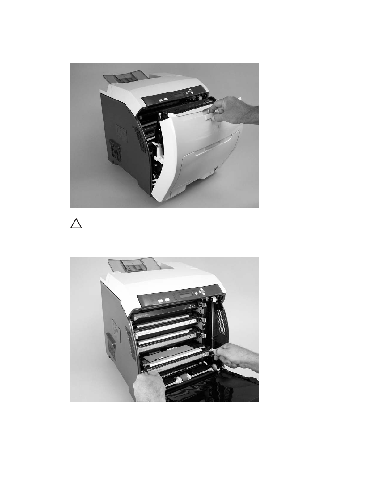
To replace the print cartridge
1. Open the front cover and ETB unit.
CAUTION: Do not place any item on the transfer unit while it is open. If the transfer unit
is punctured, print-quality problems could result.
2. Remove the used print cartridge from the printer.
36 Chapter 3 Maintenance ENWW
Page 49

3. Remove the new print cartridge from the bag, and remove the tape-seal. Place the used print
cartridge in the bag for recycling.
4. Align the print cartridge with the tracks inside the printer and insert the cartridge until it is
completely seated.
NOTE: Use the blue cartridge handles when installing the new cartridge in the printer.
Touching other areas of the print cartridge can damage the image drum and cause printquality defects.
NOTE: If a cartridge is in the wrong slot, the message INCORRECT COLOR
CARTRIDGE appears on the control panel.
5. Close the front cover and then close the top cover. After a short while, Ready appears on the
control panel.
6. Installation is complete. Place the used print cartridge in the box that the new cartridge came in.
See the enclosed recycling guide for recycling instructions.
7. If you are using a non-HP print cartridge, check the control panel for further instructions.
For additional help, go to
http://www.hp.com/support/clj3800, or http://www.hp.com/support/cljcp3505.
http://www.hp.com/support/clj3000, http://www.hp.com/support/clj3600,
ENWW Managing the print cartridge 37
Page 50

Cleaning the printer
Clean the outer surfaces with an HP Toner Cleaning Cloth or a water-dampened cloth.
WARNING! Before you begin these steps, turn the printer off and unplug all power cords to
avoid shock hazard. Be careful when cleaning around the fuser area. It might be hot.
CAUTION: To avoid permanent damage to the print cartridge, do not use ammonia-based
cleaners on or around the printer. If toner gets on your clothes, wipe it off with a dry cloth and
wash your clothes in cold water. Hot water sets toner into fabric.
Component Cleaning Method
Outer covers Use an HP Toner Cleaning Cloth (part number 5090-3379)
Inside, general With a dry, lint-free cloth, wipe any dust, spilled toner, and
or a water-dampened cloth. Do not use solvents or ammoniabased cleaners.
paper particles from the paper path area, the registration
roller, and the print-cartridge cavity.
ETB attaching roller Clean with lint-free paper. If dirt cannot be removed,
Paper-pickup rollers Clean with lint-free paper. If dirt cannot be removed,
Cleaning spilled toner
Defective print cartridges can develop leaks. Also, after a jam has occurred, some toner might
remain on the rollers and guides inside the printer. The pages that print immediately after the jam
can pick up this toner. Use a vacuum that is designed for picking up fine particles. See
specifications on page 38.
CAUTION: When cleaning the printer, do not touch the ETB with the damp cloth or with your
fingers.
Vacuum specifications
Do not use a conventional vacuum to vacuum the printer or any spilled toner. The toner particles
used in this product might be too fine for effective vacuuming and could result in damage to
conventional vacuums.
You can use a vacuum specifically designed for cleaning if it can filter fine particles (5 microns in
diameter).
dampen the paper with alcohol.
dampen the paper with alcohol.
Vacuum
38 Chapter 3 Maintenance ENWW
Page 51

Calibrating the printer
Calibration is a printer function that optimizes print quality. If you experience any print-quality
problems, calibrate the printer.
1. Press Menu.
2.
3.
4.
Press
Press
Press
to highlight CONFIGURE DEVICE, and then press .
to highlight PRINT QUALITY, and then press .
to highlight FULL CALIBRATE NOW, and then press .
ENWW Calibrating the printer 39
Page 52
Tools for troubleshooting
Using printer information pages
NOTE: Printer information pages for the HP Color LaserJet 3600 Series printer are available
in English only.
Page description How to print the page
Menu map
Shows the control-panel menus and
available settings
Configuration page
Shows printer settings and installed
accessories
Supplies status page
Shows print-cartridge toner levels
Usage page
(HP Color LaserJet 3000, 3800, and
CP3505 Series printers only)
Shows a page count for each size of
paper printed, the number of onesided (simplexed) or two-sided
(duplexed) pages, and the average
percentage of coverage for each color
1. Press Menu.
2.
Press
3.
If PRINT MENU MAP is not highlighted, press
highlighted, and then press
The content of the menu map varies, depending on the options currently installed
in the printer.
1. Press Menu.
2.
Press
3.
Press
1. Press Menu.
2.
Press
3.
Press
1. Press Menu.
2.
Press
3.
Press
to highlight INFORMATION, and then press .
or until it is
.
to highlight INFORMATION, and then press .
to highlight PRINT CONFIGURATION, and then press .
NOTE: If the printer contains an HP Jetdirect print server or an optional
hard-disk accessory, an additional configuration page prints that provides
information about those devices.
to highlight INFORMATION, and then press .
to highlight PRINT SUPPLIES STATUS PAGE, and then press .
to highlight INFORMATION, and then press .
to highlight PRINT USAGE PAGE, and then press .
Demo page
Shows a color photograph that allows
you to check print quality
Color usage log
Shows color-use statistics for the
printer
1. Press Menu.
2.
Press
3.
Press
1. Press Menu.
2.
Press
3.
Press
to highlight INFORMATION, and then press .
to highlight PRINT DEMO, and then press .
to highlight INFORMATION, and then press .
to highlight PRINT COLOR USAGE JOB LOG, and then press .
40 Chapter 3 Maintenance ENWW
Page 53

Page description How to print the page
File directory
(HP Color LaserJet 3000, 3800, and
CP3505 Series printers only)
Shows information for all installed
mass-storage devices
PCL or PS font list
(HP Color LaserJet 3000, 3800, and
CP3505 Series printers only)
Shows which fonts are currently
installed in the printer
Configuring e-mail alerts
NOTE: If your host software does not support e-mail, this feature might not be available on
the HP Color LaserJet 3600 Series printer.
1. Press Menu.
2.
Press
3.
Press
1. Press Menu.
2.
Press
3.
Press
then press
to highlight INFORMATION, and then press .
to highlight PRINT FILE DIRECTORY, and then press .
NOTE: This option does not appear if no mass-storage devices are
installed.
to highlight INFORMATION, and then press .
to highlight PRINT PCL FONT LIST or PRINT PS FONT LIST, and
NOTE: The font lists also show which fonts are resident on an optional
hard-disk accessory or flash DIMM.
.
You can use HP Web Jetadmin or the embedded Web server to configure the system to alert you of
problems with the printer. The alerts take the form of e-mail messages to the e-mail account(s) that
you specify.
Configure the following items:
The printer(s) that you want to monitor
●
The alerts that you want to receive (for example, alerts for jams, paper out, supplies status, and
●
cover open)
The e-mail account(s) to which the alerts should be forwarded
●
Software Information location
HP Web Jetadmin See HP Web Jetadmin on page 15 for general information about HP Web Jetadmin.
See the HP Web Jetadmin Help system for details about alerts and how to set them up.
Embedded Web server See Using the embedded Web server on page 41 for general information about the
embedded Web server.
See the embedded Web server Help system for details about alerts and how to set them
up.
Using the embedded Web server
NOTE: The HP Color LaserJet 3600 Series printer embedded Web server provides network
configuration and status information only.
ENWW Tools for troubleshooting 41
Page 54

NOTE: When the printer is directly connected to a computer, use the HP Easy Printer Care
Software to view the printer status.
View printer-control status information.
●
Set the type of media that is loaded in each tray.
●
Determine the remaining life of all supplies and order new ones.
●
View and change tray configurations.
●
View and change the printer control-panel menu configuration.
●
View and print internal pages.
●
Receive notification of printer and supplies events.
●
View and change network configuration.
●
View support content that is specific to the current state of the printer.
●
Restrict access to color printing features (HP Color LaserJet 3000, 3800, and CP3505 Series
●
printers only).
When the printer is connected to the network, the embedded Web server is automatically available.
You can open the embedded Web server from Windows 95 and later.
Use the embedded Web server to view printer and network status and to manage printing functions
from your computer instead of from the printer control panel.
To use the embedded Web server, you must have Microsoft Internet Explorer 4 and later or
Netscape Navigator 4 and later. The embedded Web server works when the printer is connected to
an IP-based network. The embedded Web server does not support IPX-based or AppleTalk printer
connections. You do not need Internet access to open and use the embedded Web server.
To open the embedded Web server by using a network connection
1. In a supported Web browser on your computer, type the IP address for the printer in the URL
field. (To find the IP address, print a configuration page. See
on page 40.)
NOTE: After you open the URL, you can bookmark it so that you can return to it quickly
in the future.
2. The embedded Web server has three tabs that contain settings and information about the
printer: the Information tab, the Settings tab, and the Networking tab. Click the tab that you
want to view.
See the following section for more information about each tab.
Using printer information pages
42 Chapter 3 Maintenance ENWW
Page 55

Embedded Web server sections
Tab or section Description
Information tab
Provides printer, status, and
configuration information
Device Status: Shows the printer status and shows the life remaining of
●
HP supplies, with 0% indicating that a supply is empty. The page also shows the
type and size of print media set for each tray. To change the default settings, click
Change Settings.
Configuration Page: Shows the information that is on the printer configuration
●
page.
Supplies Status: Shows the life remaining of HP supplies, with 0% indicating that
●
a supply is empty. This page also provides supplies part numbers. To order new
supplies, click Order Supplies in the Other Links area on the left side of the
window.
Event log: Shows a list of all printer events and errors.
●
Usage page: Shows a summary of the number of pages the printer has printed,
●
grouped by size and type.
Diagnostics Page: Provides information about printer calibration, color density,
●
and other parameters.
Device Information: Shows the printer network name, address, and model
●
information. To change these entries, click Device Information on the Settings
tab.
● Control Panel: Shows messages from the printer control panel.
Color Usage Job Log: Shows color print jobs on a job-by-job basis.
●
Print: Use to send print jobs to the printer.
●
Settings tab
Provides the ability to configure
the printer from your computer
● Configure Device: Use to configure printer settings. This page contains the
traditional menus found on printers using a control-panel display.
E-mail Server: Network only. Use in conjunction with the Alerts page to set up
●
incoming and outgoing e-mail, as well as to set e-mail alerts.
Alerts: Network only. Use to set up to receive e-mail alerts for various printer and
●
supplies events.
AutoSend: Use to configure the printer to send automated e-mails regarding
●
printer configuration and supplies to specific e-mail addresses.
Security: Use to set a password that must be typed to gain access to the
●
Settings and Networking tabs. Enable and disable certain features of the
embedded Web server.
Edit Other Links: Use to add or customize a link to another Web site. This link is
●
displayed in the Other Links area on all embedded Web server pages.
Device Information: Use to name the printer and assign an asset number to it.
●
Type the name and e-mail address for the primary contact who will receive
information about the printer.
Language: Use to specify the language in which to display the embedded Web
●
server information.
Date & Time: Synchronizes with a network time server.
●
ENWW Tools for troubleshooting 43
Page 56

Tab or section Description
Wake Time: Use to set or edit a wake time for the printer.
●
Restrict Color: Use to set color-print-job user restrictions.
●
NOTE: The Settings tab can be password-protected. If this printer is on a
network, always consult with the printer administrator before changing settings
on this tab.
Networking tab
Provides the ability to change
network settings from your
computer
Other links
Contains links that connect you to
the Internet
Network administrators can use this tab to control network-related settings for the
printer when it is connected to an IP-based network. This tab does not appear if the
printer is directly connected to a computer, or if the printer is connected to a network
using anything other than an HP Jetdirect print server.
NOTE: The Networking tab can be password-protected. If this printer is on a
network, always consult with the printer administrator before changing settings
on this tab.
HP Instant Support™: Connects to the HP Web site to help you find solutions.
●
This service analyzes the printer error log and configuration information to provide
diagnostic and support information specific to your printer.
Order Supplies: Connects to the HP Web site to order genuine HP supplies.
●
Product Support: Connects to the support site for the printer for help regarding
●
general topics.
NOTE: Internet access is necessary in order to use any of these links. If you
use a dial-up connection and did not connect when you first opened the
embedded Web server, you must connect before you can visit these Web
sites. Connecting might require that you close the embedded Web server and
reopen it.
Using the HP Easy Printer Care Software
Use the HP Easy Printer Care Software for the following tasks:
Check the printer status.
●
Check supplies status.
●
Set up alerts.
●
Gain access to troubleshooting and maintenance tools.
●
Use the HP Easy Printer Care Software when the printer is directly connected to your computer or
when it is connected to a network. A complete software installation is necessary in order to use the
HP Easy Printer Care Software.
NOTE: You do not have to have Internet access to open and use the HP Easy Printer Care
Software. However, if you click a Web-based link, you must have Internet access to go to the
site that is associated with the link.
Supported operating systems
The HP Easy Printer Care Software is supported for Windows 2000 and Windows XP.
44 Chapter 3 Maintenance ENWW
Page 57

To use the HP Easy Printer Care Software
Use one of the following methods to open HP Easy Printer Care Software:
On the Start menu, select Programs, select HP, and then select HP Easy Printer Care
●
Software.
In the Windows system tray (in the lower-right corner of the desktop), double-click the HP Easy
●
Printer Care Software icon.
Double-click the desktop icon.
●
HP Easy Printer Care Software sections
Section Description
Overview tab
Contains basic status
information for the printer
Support tab
Provides help
information and links
Supplies Ordering
window
Provides access to
online or e-mail supplies
ordering
Devices list: Shows the printers that you can select.
●
Device Status section: Shows printer status information, including printer alert conditions,
●
such as an empty print cartridge; device-identification information; control-panel messages;
and print-cartridge levels. After correcting a printer problem, click
Supplies Status section: Shows detailed supplies status, such as the percentage of toner
●
remaining in the print cartridges and the status of the media that is loaded in each tray.
Supplies Details link: Opens the supplies status page to view more detailed information
●
about printer supplies, ordering information, and recycling information.
Provides device information, including alerts for items that need attention.
●
Provides links to troubleshooting information and tools.
●
Provides links to the HP Web site for registration and support, and for ordering supplies.
●
NOTE: Connect to the Internet to visit these Web sites.
Ordering list: Shows the supplies that can be ordered for each printer. To order a certain
●
item, click the Order check box for that item in the supplies list.
Shop Online for Supplies: Opens the HP supplies Web site in a new browser window.
●
The information about selected items can be transferred to the Web site.
Print Shopping List: Prints the information about the selected supplies.
●
Email Shopping List: Creates a text list of selected items. The list can be copied into an e-
●
mail message that is sent to a supplier.
to update the section.
NOTE: Connect to the Internet to visit these Web sites.
Alert Settings window
Use to configure the
printer to automatically
notify of printer issues
Activate or deactivate the alerts feature for a certain printer.
●
● Set when you want alerts to appear—either when printing to that particular printer, or
whenever a printer event occurs.
Set alerts for only critical errors or for any error, including continuable errors.
●
Set what type of alert should appear (pop-up message or system tray alert, and e-mail
●
message).
ENWW Tools for troubleshooting 45
Page 58

Section Description
Device List tab
Shows information
about each printer in the
Devices list
Find Other Printers
window
Use to add more
printers to the printer list
Printer information, including printer name, make, and model
●
An icon (if the View as drop-down box is set to Tiles, which is the default setting)
●
Any current alerts for the printer
●
If you click a printer in the list, the HP Easy Printer Care Software opens the Overview tab for
that printer.
Clicking the Find Other Printers link in the Devices list opens the Find Other Printers window.
The window provides a utility that detects other network printers that can be added to the
Devices list and then monitored from a computer.
Using the HP Printer Utility for Macintosh
To open the HP Printer Utility in Mac OS X V10.2
1. Open the Finder and click Applications.
2. Click Library and click Printers.
3. Click hp and click Utilities.
4. Double-click HP Printer Selector to open the HP Printer Selector.
5. Select the printer that you want to configure, and then click Utility.
To open the HP Printer Utility in Mac OS X V10.3
1. In the Dock, click the Printer Setup Utility icon.
NOTE: If the Printer Setup Utility icon does not appear in the Dock, open the Finder,
click Applications, click Utilities, and then double-click Printer Setup Utility.
2. Select the printer that you want to configure, and then click Utility.
HP Printer Utility features
The HP Printer Utility consists of pages that you open by clicking in the Configuration Settings list.
The following table describes the tasks that you can perform from these pages.
Item Description
Color Cleaning Prints a cleaning page.
Configuration Page Prints a configuration page.
Supplies Status Shows the printer supplies status and provides links for online supplies-ordering.
HP Support Provides access to technical assistance, online supplies ordering, online registration,
and recycling and return information.
File Upload Transfers files from the computer to the printer.
Upload Fonts Transfers font files from the computer to the printer.
46 Chapter 3 Maintenance ENWW
Page 59

Item Description
Firmware Update Transfers updated firmware files from the computer to the printer.
Duplex Mode Turns on the automatic two-sided printing mode.
Economode Toner Density Turns on the Economode setting to conserve toner, or adjusts toner density.
Resolution Changes the resolution settings, including the REt setting.
Lock Resources Locks or unlocks storage devices, such as a hard disk.
Stored Jobs Manages print jobs that are stored on the printer hard disk.
Trays Configuration Changes the default printer tray settings.
IP Settings Changes the printer network settings and provides access to the embedded Web server.
Additional Settings Provides access to the embedded Web server.
E-mail Alerts Configures the printer to send e-mail notices for certain events.
ENWW Tools for troubleshooting 47
Page 60

48 Chapter 3 Maintenance ENWW
Page 61

4 Theory of operation
This chapter presents an overview of the major components of the HP Color LaserJet
3000/3600/3800/CP3505 Series printers, and includes a detailed discussion of the image-formation
system.
Engine control system
●
Laser/scanner system
●
Pickup-and-feed-system
●
Image-formation system
●
ENWW 49
Page 62
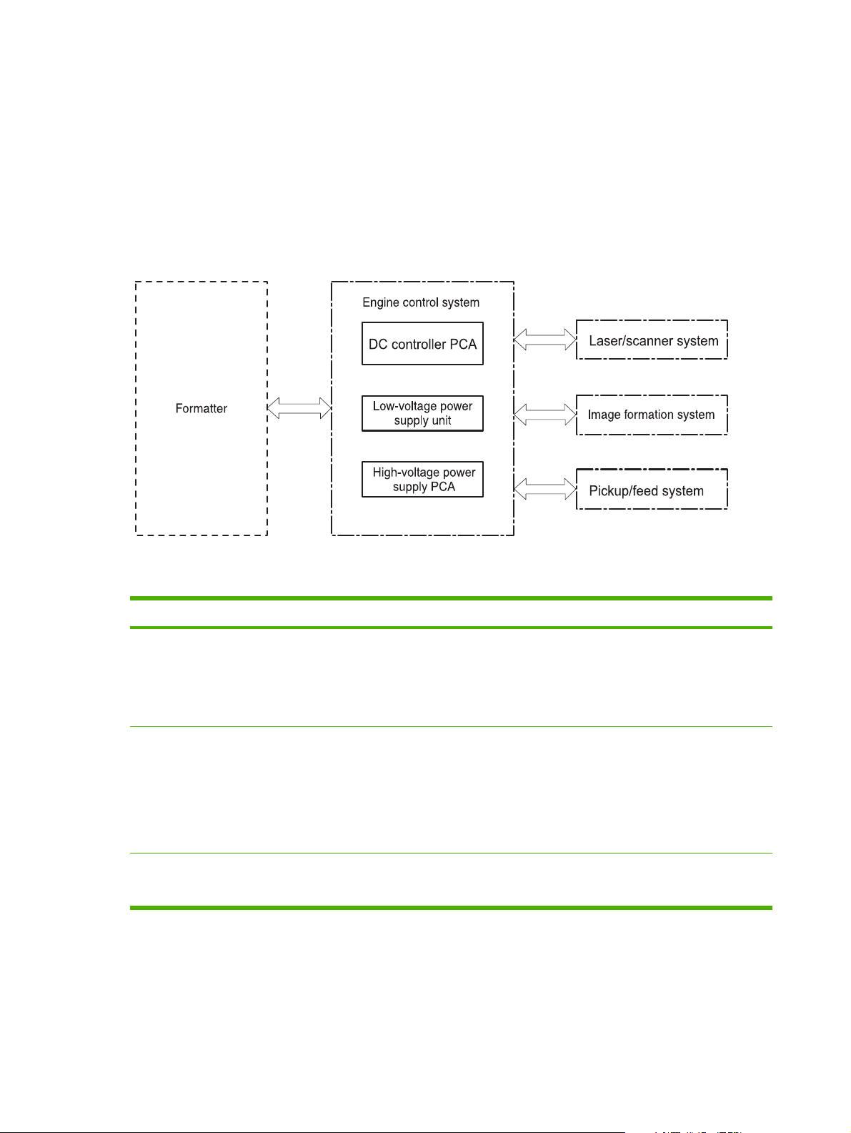
Engine control system
The engine control system coordinates all printer functions and drives the other three systems.
The engine control system contains these components:
DC controller
●
High-voltage power-supply PCB
●
Low-voltage power unit
●
Figure 4-1 Engine control system components
Table 4-1 Sequence of operation
Period Duration Purpose Remarks
WAIT From the time the power is
turned on or the door is
closed until the drum-phase
adjustment is complete
STBY (Standby period) From end of the WAIT or
LSTR period until either the
print command is received
from the formatter or the
power is turned off
INTR (Initial rotation) From the time the print
command is received until
the media is picked up
Clears the potential from the
drum surface, adjusts the
drum phase, and cleans the
ETB
Maintains the printer in
readiness for a print
command
Prepares the photosensitive
drum for printing
Detects the toner level,
cartridge presence, and
environment; completes any
required calibration (color
registration control and
image stability)
The printer enters sleep
mode when the formatter
sends a sleep command,
and performs color
registration and the image
stability control when the
formatter sends those
commands
50 Chapter 4 Theory of operation ENWW
Page 63
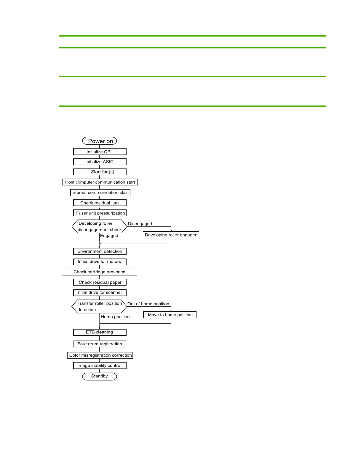
Table 4-1 Sequence of operation (continued)
Period Duration Purpose Remarks
PRINT From the end of INTR period
LSTR (Last rotation) From the end of the PRINT
Power-on sequence
until the fuser paper delivery
sensor detects the trailing
edge of paper
period until the delivery
motor stops rotating
Forms the images on the
photosensitive drum and
transfers the toner image to
the print media
Moves the printed sheet out
of the printer
Performs image stabilization
at a specified print interval or
at specified times
The printer enters the INTR
period as soon as the
formatter sends another
print command
Figure 4-2 Power-on sequence
ENWW Engine control system 51
Page 64
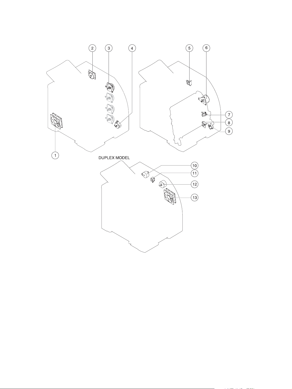
Motors, fans, and solenoids
Figure 4-3 Motors, fans, and solenoids
1. Main fan (FM1)
2. Fuser drive motor (M1)
3. Print-cartridge drive motors (M6, M7, M8, M9))
4. Pickup-and-feed motor (M4)
5. Developing separation solenoids (SL5014, SL5015)
6. ETB drive motor (M5)
7. Developing separation solenoid (SL5011)
8. Cassette pickup solenoid (SL5012)
52 Chapter 4 Theory of operation ENWW
Page 65

9. Multipurpose tray pickup solenoid (SL5013)
NOTE: The following parts are included only on duplexing printer models.
10. Duplex reverse-drive motor (M11)
11. Duplex flapper solenoid (SL10)
12. Duplex-feed-drive motor (M10)
13. Door fan (duplex models only) (FM2)
ENWW Engine control system 53
Page 66
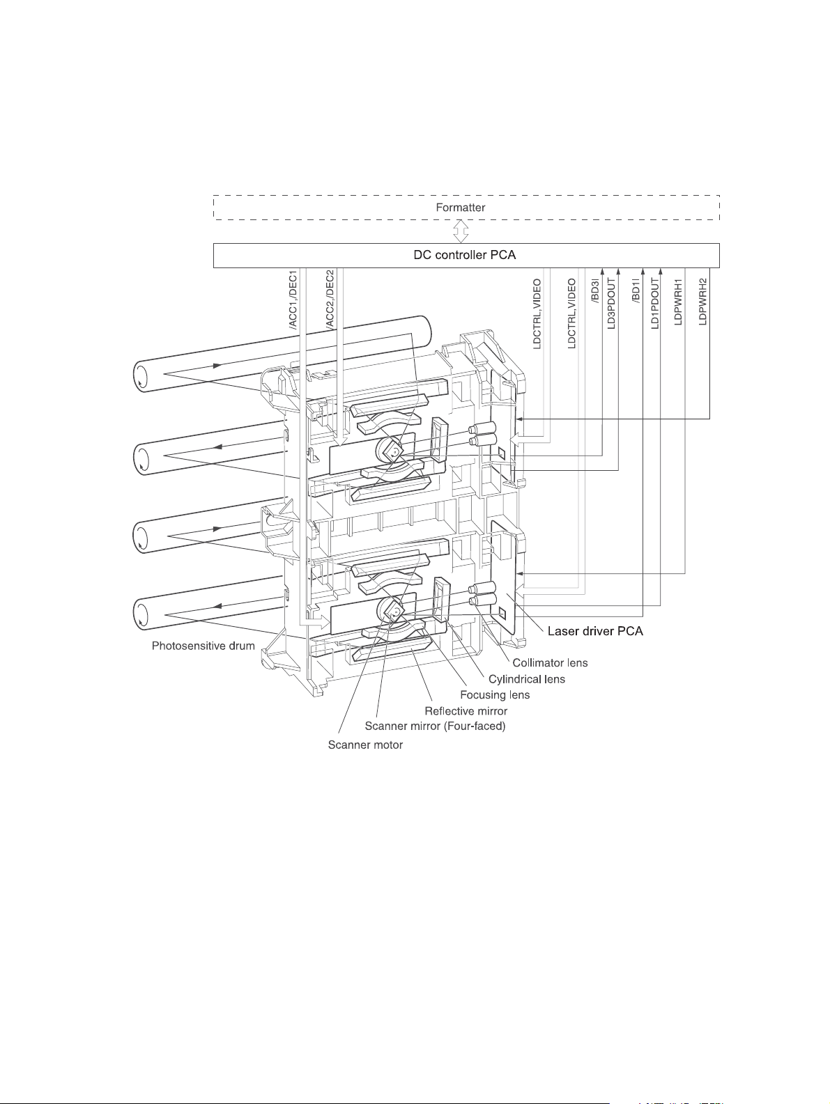
Laser/scanner system
The formatter sends video signals to the DC controller, which controls the laser/scanner. When the
laser/scanner system receives those signals it converts them to latent images on the photosensitive
drum.
Figure 4-4 Laser/scanner system
54 Chapter 4 Theory of operation ENWW
Page 67
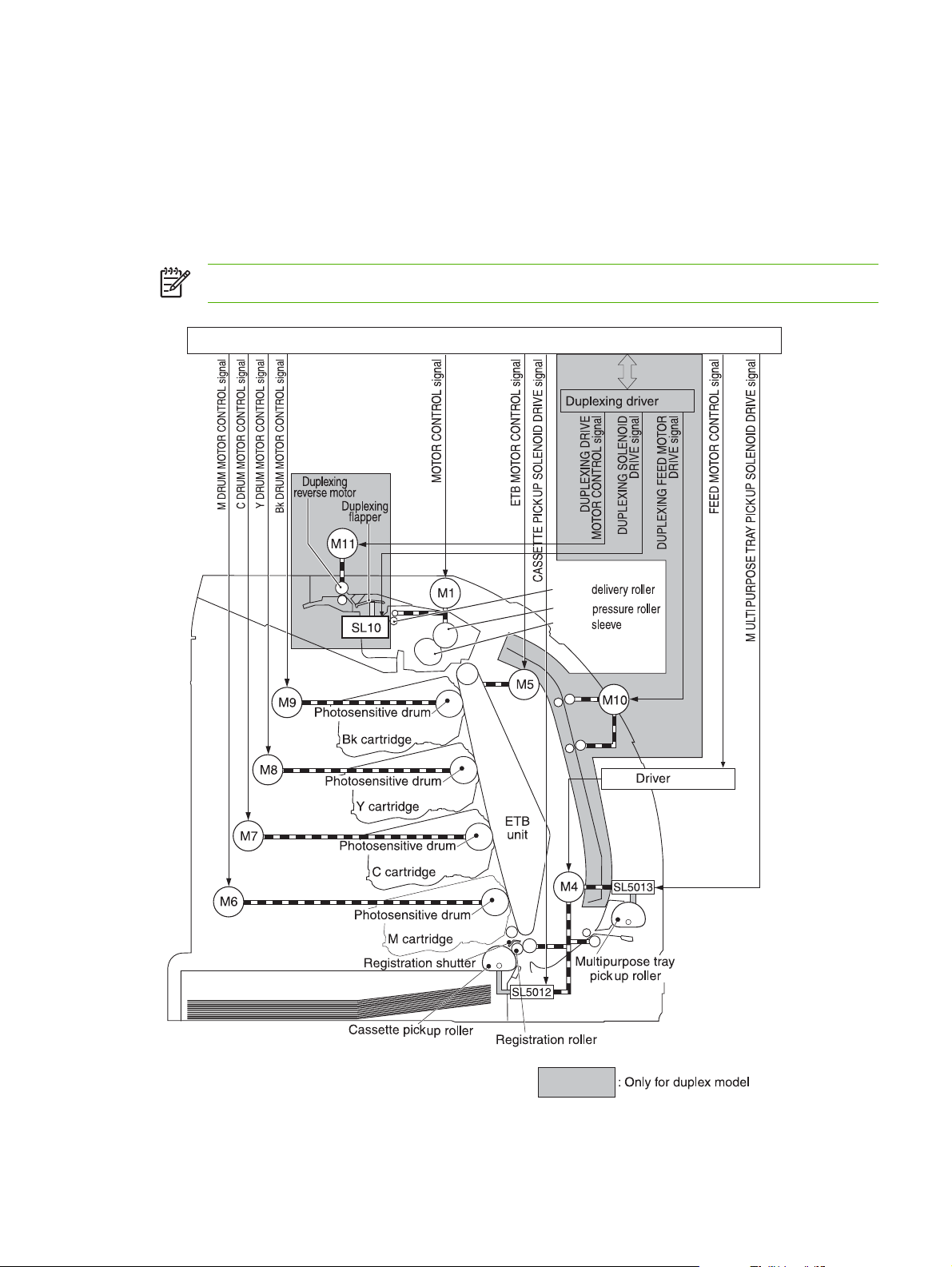
Pickup-and-feed-system
The pickup and feed system consists of several types of feed rollers and sensors.
The DC controller drives the system by controlling the feed motor (M4), ETB motor (M5), and four
drum motors (M6, M7, M8, M9) and the solenoids for the trays. In models that include an automatic
duplex accessory, the duplexing feed motor (M10) and reversing motor (M11) are also part of the
system.
NOTE: Tray 2 must be installed in order to print from tray 1 or tray 3.
DC controller PCA
PCA
Fuser
Fuser
Fuser
Fuser
PCA
Figure 4-5 Pickup-and-feed system
ENWW Pickup-and-feed-system 55
Page 68

Sensors in the pickup-and-feed system trays (cassettes)
Paper sensors detect media in the trays. Other sensors react to the media as it moves through the
paper path. If the media does not reach or pass each sensor within a specified time period, the DC
controller determines that a jam has occurred and alerts the formatter. In models that include an
automatic duplex accessory, the paper path contains additional sensors that detect movement
through the duplex path.
Figure 4-6 Pickup-and-feed system sensors
SR705 Fuser pressure-release sensor
SR706 Output-bin-full sensor
SR707 Multipurpose-tray paper sensor
SR708 Multipurpose-tray paper-position sensor (HP Color LaserJet 3000, 3800, and CP3505 Series printers only)
56 Chapter 4 Theory of operation ENWW
Page 69

SR709 Cassette paper-presence sensor
SR710 Top-of-page sensor
SR714 One-sided paper sensor
SR6001 Paper-loop sensor
SR6005 Fuser paper delivery sensor
SW2 Cassette-presence switch
Cassette pickup mechanism
When the cassette is correctly installed, SW2 detects its presence. The cassette paper sensor
(SR709) detects whether media is present in the cassette, and the cassette media sensor detects
the type of media. When the cassette is correctly installed and the correct media type is present, the
cassette pickup operation begins.
1. The DC controller receives a print command from the formatter, and then begins rotating the
pickup-and-feed motor (M4) at the correct speed for the media type.
2. After the motor reaches the correct speed and the fuser is at the correct temperature, the
cassette pickup solenoid (SL5012) turns on and the cassette pickup roller begins rotating.
3. The cassette lifting plate lifts the paper stack, and the cassette pickup roller picks up one sheet
of media. The separation pad prevents multi-feeds.
Figure 4-7 Cassette pickup mechanism
ENWW Pickup-and-feed-system 57
Page 70
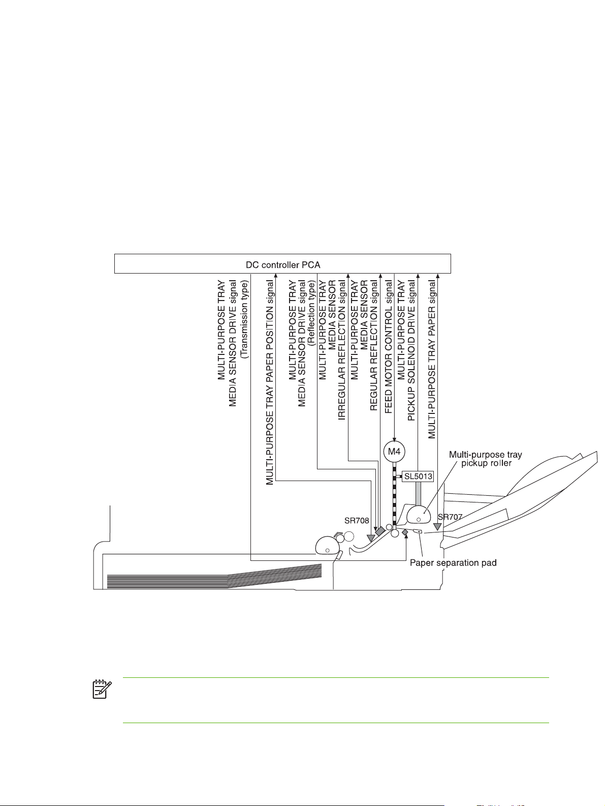
Multipurpose-tray pickup mechanism
The cassette must be installed in order for the multipurpose (MP) tray to operate. The MP tray paper
sensor (SR707) detects whether media is present in the MP tray. When the cassette is correctly
installed and media is present, the MP tray pickup operation begins.
1. The DC controller receives a print command from the formatter, and then begins rotating the
pickup-and-feed motor (M4) at the correct speed for the media type.
2. After the motor reaches the correct speed and the fuser is at the correct temperature, the MP
pickup solenoid (SL5013) turns on and the MP pickup roller begins rotating.
3. The MP pickup roller picks up one sheet of media. The separation pad prevents multi-feeds.
4. When the media reaches SR708, motor M4 stops, the MP tray media sensor detects the media,
and then motor M4 restarts and resumes feeding media into the printer.
Figure 4-8 Multipurpose-tray pickup mechanism
Feed-speed control
To optimize print quality, the pickup-and-feed motor rotates at different speeds depending on the
type of media.
NOTE: In the following table, normal speed is 22 ppm for the HP CLJ 3800 and CP3505
models, and normal speed is 18 ppm for the HP CLJ 3600 models. Normal speed is 30 ppm
for the HP CLJ 3000 model (black mode only).
58 Chapter 4 Theory of operation ENWW
Page 71

Media type HP CLJ 3800 and
CP3505
Plain 22 ppm 17.6 to 18 ppm 15 ppm 30 ppm
Rough 17.6 to 18 ppm 17.6 to 18 ppm 15 ppm 15 ppm
Thin 22 ppm 17.6 to 18 ppm 15 ppm 30 ppm
Thick 17.6 to 18 ppm 17.6 to 18 ppm 15 ppm 15 ppm
Thicker 17.6 to 18 ppm 17.6 to 18 ppm 15 ppm 15 ppm
Postcard 17.6 to 18 ppm 17.6 to 18 ppm 15 ppm 15 ppm
Thicker postcard 11 ppm 11 ppm 15 ppm 15 ppm
Glossy 17.6 to 18 ppm 17.6 to 18 ppm 15 ppm 15 ppm
Heavy Glossy 11 ppm 11 ppm 15 ppm 15 ppm
Extra Heavy glossy 8.8 to 9 ppm 8.8 to 9 ppm 15 ppm 15 ppm
Envelope 17.6 to 18 ppm 17.6 to 18 ppm 15 ppm 15 ppm
Label 17.6 to 18 ppm 17.6 to 18 ppm 15 ppm 15 ppm
Gloss film 3.6 ppm 3.6 ppm 15 ppm 15 ppm
Transparency 3.6 ppm 3.6 ppm 15 ppm 15 ppm
HP CLJ 3600 HP CLJ 3000 (full-
color mode)
HP CLJ 3000
(monochrome mode)
ENWW Pickup-and-feed-system 59
Page 72
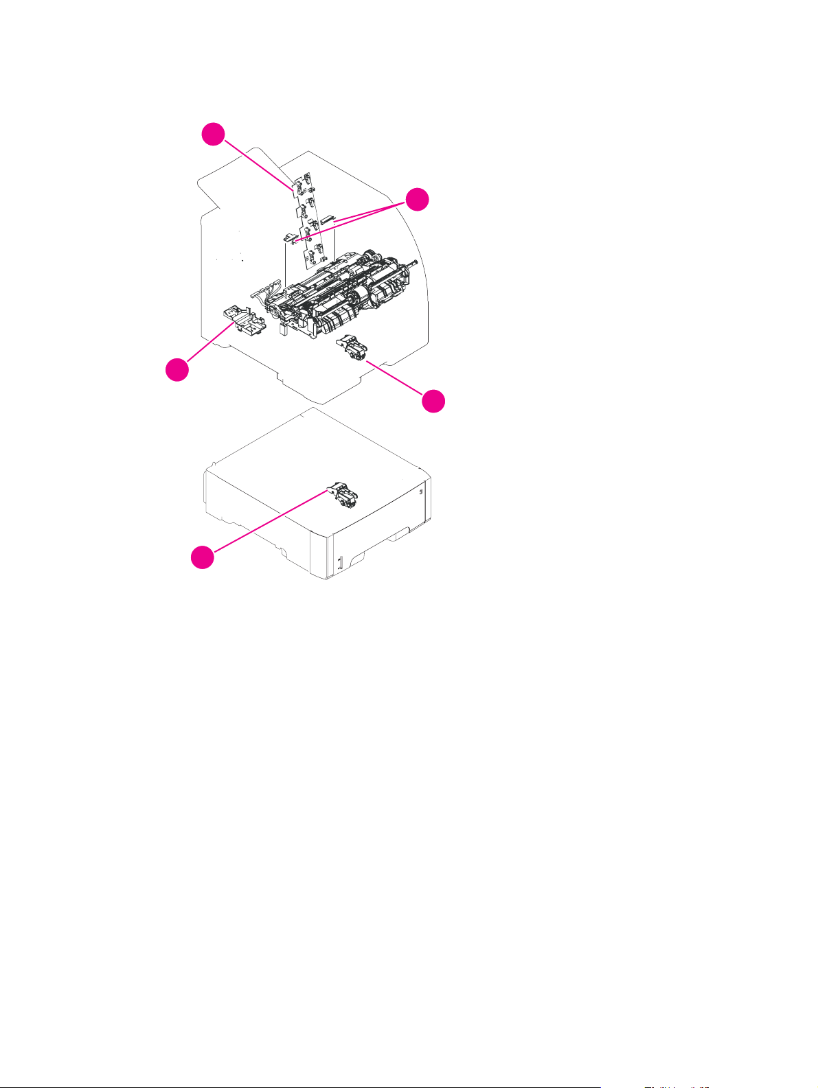
Sensor jam detection
1
4
2
3
55
1. Cartridge sensor assembly
2. Paper and registration sensor covers
3. Cassette media sensor (HP Color LaserJet 3600, 3800, CP3505 only)
4. Temperature sensor
5. Media-sensor assembly (500-sheet feeder)
60 Chapter 4 Theory of operation ENWW
Page 73

The following jams can occur during operation:
Pick-up delay jam. The printer makes three attempts to pick up media from a tray. When the top-
●
of-page sensor (SR710) does not detect the leading edge of a page within a specific time after
the third attempt, the printing operation stops. The time varies depending on the printer model
and the media source, as follows.
HP CLJ 3000: 1.3 seconds from the cassette; 2.2 seconds from the multipurpose tray (tray 1);
2.3 seconds from the paper feeder
HP CLJ 3600: for black printing, 1.0, 1.5, or 1.6 seconds; for color printing, 1.7, 2.7, or 2.9
seconds
HP CLJ 3800 and CP3505: 1.3 seconds from the cassette; 2.2 seconds from the multipurpose
tray (tray 1); 2.3 seconds from the paper feeder
● Pick-up stationary jam. The printing operation stops when the top-of-page sensor (SR710) does
not detect the trailing edge of a page within a specific time after it has detected the leading edge.
HP CLJ 3000: approximately 3.2 seconds
HP CLJ 3600: for black printing in Normal mode, 2.3 seconds; for color printing in Normal mode,
4.6 seconds
HP CLJ 3800 and CP3505: approximately 4.0 seconds
Delivery delay jam. The printing operation stops when the fuser paper delivery sensor (SR6005)
●
does not detect the leading edge of a page within a specific time after it has detected the
leading edge.
HP CLJ 3000: approximately 3.0 seconds (in Normal print mode)
HP CLJ 3600: for black printing in Normal mode, 2.2 seconds; for color printing in Normal mode,
3.8 seconds
HP CLJ 3800 and CP3505: approximately 3.8 seconds (in Normal print mode)
Wrapping jam. The printing operation stops when the fuser paper delivery sensor (SR6005)
●
does not detect any media within a specific time. The time varies depending on the length of the
media that the top-of-page sensor (SR710) detected.
HP CLJ 3000: approximately 1.9 seconds (in Normal print mode with letter-size media)
HP CLJ 3600: for black printing in Normal mode with letter-size media, 1.3 seconds; for color
printing in Normal mode with letter-size media, 2.4 seconds
HP CLJ 3800 and CP3505: approximately 2.4 seconds (in Normal print mode with letter-size
media)
Delivery stationary jam. The printing operation stops when the fuser paper delivery sensor
●
(SR6005) continues to detect paper for a specific time after the top-of-page sensor (SR710)
detected its presence.
HP CLJ 3000: approximately 3.1 seconds (in Normal print mode)
HP CLJ 3600: for black printing in Normal mode, 2.2 seconds; for color printing, 3.9 seconds
HP CLJ 3800 and CP3505: approximately 3.9 seconds (in Normal print mode)
ENWW Pickup-and-feed-system 61
Page 74

Duplexing pickup delay jam (for models that include an automatic duplex accessory). The
●
printing operation stops when the top-of-page sensor (SR710) does not detect the leading edge
of the second side of the paper within a specific time after the duplexing feed motor (M10)
started rotating.
HP CLJ 3000: approximately 2.0 seconds (in Normal print mode)
HP CLJ 3600: for black printing in Normal mode, 1.4 seconds; for color printing, 2.5 seconds
HP CLJ 3800 and CP3505: approximately 2.5 seconds (in Normal print mode)
Residual-paper jam. The printing operation stops when any of the following sensors detects
●
media during the initial sequence period:
Top-of-page sensor (SR710)
Paper-loop sensor (SR6001)
Fuser paper delivery sensor (SR6005)
Duplexing reverse sensor (SR823)
Multipurpose tray (MPT) paper-position sensor (SR708)
Door-open jam. The printing operation stops when the DC controller detects that a printer door
●
is open.
62 Chapter 4 Theory of operation ENWW
Page 75
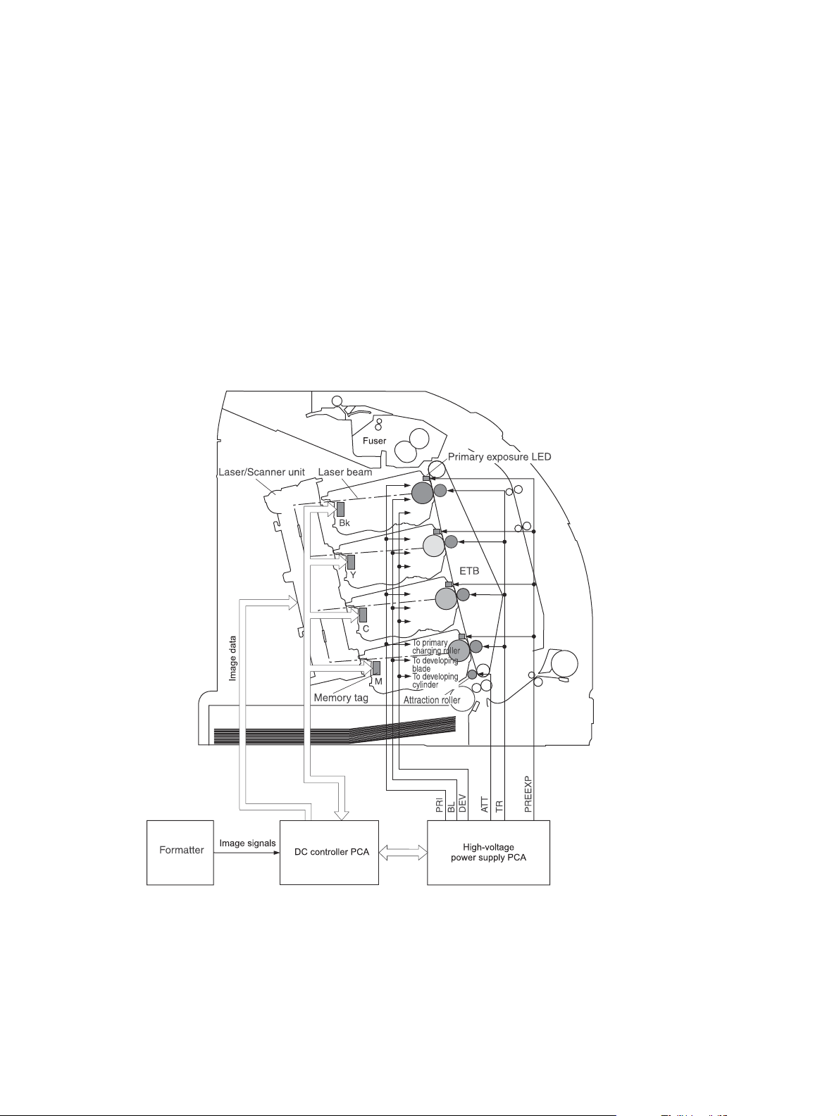
Image-formation system
The image-formation system, which forms a toner image on media, consists of several
interdependent systems:
Electrostatic latent-image-formation
●
● Developing
Transfer
●
Fuser
●
Drum cleaning
●
The printer includes four print cartridges that contain the toner used to create the image on the
media. Toner is applied in the following order, using only the colors necessary for a specific image:
magenta (M), cyan (C), yellow (Y), and black (Bk).
Figure 4-9 Image formation system
ENWW Image-formation system 63
Page 76

Image-formation process
Laser printing requires the interaction of several different technologies including electronics, optics,
and electrographics to provide a printed page. Each process functions independently and must be
coordinated with the other processes. Image formation consists of the following five processes:
1. Latent-image formation
2. Developing
3. Image transfer
4. Fusing
5. Transfer-belt cleaning
These processes are divided into ten steps, which are shown in
on page 65 and described in the following sections.
Figure 4-10 Image-formation steps
64 Chapter 4 Theory of operation ENWW
Page 77

Figure 4-10 Image-formation steps
Latent-image formation stage
During the three steps that comprise this stage, a latent image is formed by applying a negative
charge to the photosensitive drum. You cannot see this image on the drum.
Step 1: pre-exposure
The pre-exposure LED hits the photosensitive drum surface and eliminates any residual charge on
the surface.
ENWW Image-formation system 65
Page 78

Figure 4-11 Pre-exposure
Step 2: primary charging
A high-voltage dc bias is applied to the primary charging roller, which is made of conductive rubber
and is in contact with the drum surface. As the roller moves across the drum, it applies the negative
charge to that surface.
Step 3: laser-beam exposure
The laser beam scans the photosensitive drum to neutralize the negative charge on portions of the
drum surface. An electrostatic latent image is formed where the negative charge was neutralized.
Figure 4-12 Laser-beam exposure
Developing stage
The developing cylinder comes in contact with the photosensitive drum and deposits toner on the
electrostatic latent image.
Step 4: developing
Toner acquires a negative charge as a result of the friction from the developing cylinder rotating
against the developing blade. When the negatively charged toner comes in contact with the drum, it
adheres to the electrostatic latent image. When the toner is on the drum the image becomes visible.
Transfer stage
66 Chapter 4 Theory of operation ENWW
Page 79

Step 5: media feed
The printer generates electrostatic force to pull a sheet of print media to the ETB. The sheet adheres
to the belt and travels between the ETB engaged motor and the attraction roller.
The attraction roller transfer positive dc bias to the media so that the negatively charged toner can be
easily transferred from the drum to the sheet.
Figure 4-13 Media feed
Step 6: image transfer
The ETB carries the positively charged media over the photosensitive drum. As it passes between
the transfer roller and the drum, the transfer roller applies a positive dc bias to the belt. Negatively
charged media attracts negatively charged toner from the drum surface. This process is repeated for
each toner color.
Figure 4-14 Image transfer
Step 7: separation from the drum
The beam strength or stiffness of media combined with the ETB holding force causes the media to
separate from the drum. The sheet remains on the ETB and continues to travel through the printer.
ENWW Image-formation system 67
Page 80

Figure 4-15 Separation from the drum
Step 8: separation from the ETB
The elasticity of the print media causes it to separate from the ETB. The static-charge eliminator is
not involved during this step.
Fusing stage
Until the fusing stage is complete, the image is not permanently affixed to the print media. The toner
can be easily smudged until the heat and pressure of the fusing process fix the image to the sheet.
Step 9: fusing
The printer uses a ceramic heater to accomplish the color-on-demand fusing process. The heater
has a low heat capacity, which results in a short warm-up period and yields energy savings.
Figure 4-16 Fusing
Cleaning stage
Not all of the toner is removed from the photosensitive drum during the transfer stage. During the
cleaning stage, the residual, or waste, toner is cleared from the drum surface to prepare the surface
for the next latent-image formation.
68 Chapter 4 Theory of operation ENWW
Page 81
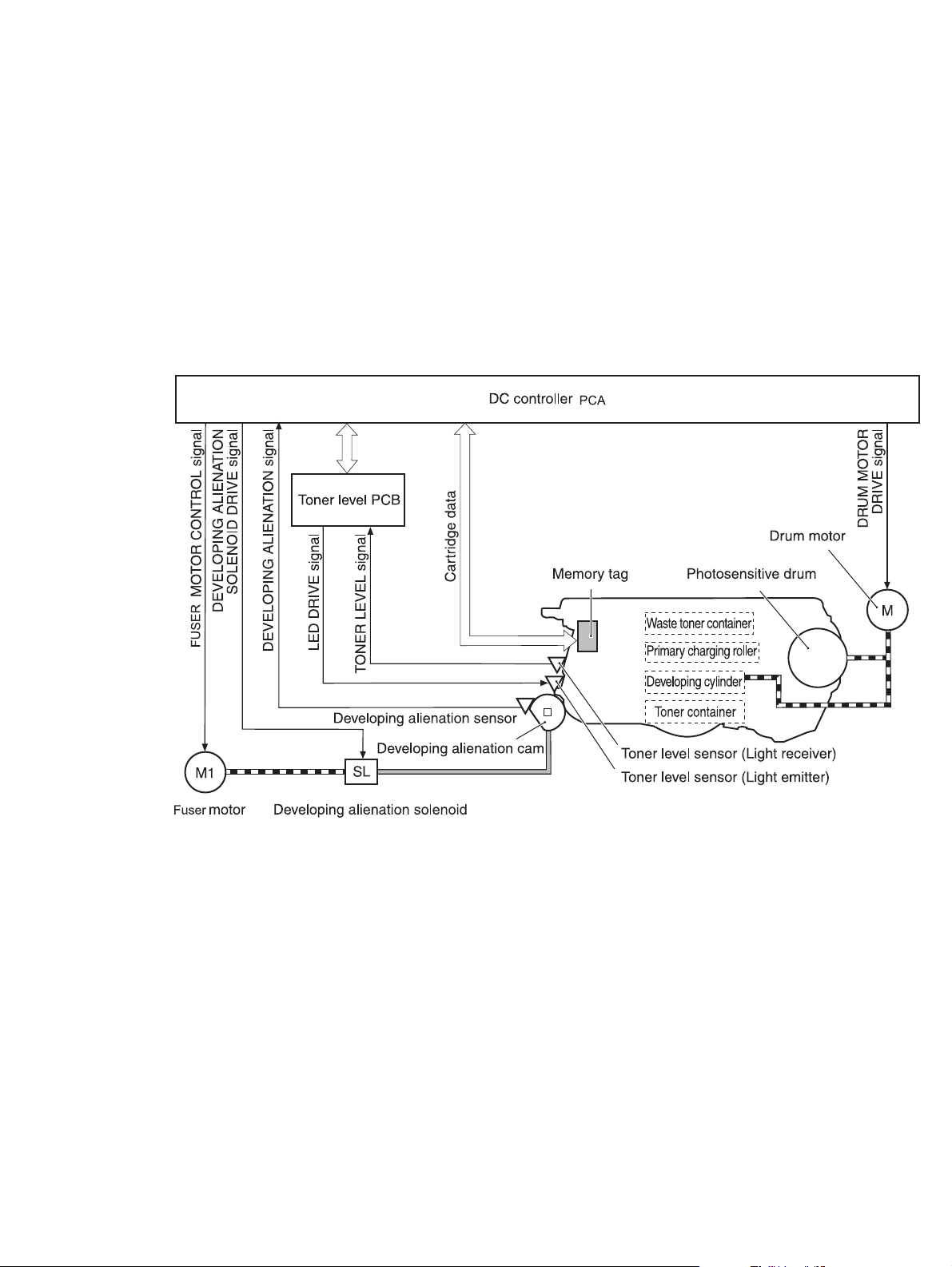
Step 10: drum cleaning
The cleaning blade scrapes the residual toner off the surface of the photosensitive drum and
deposits it in the waste-toner container. The drum is now clear, and is ready for the next imageformation process.
Print cartridge
This printer has four print cartridges: magenta (M), cyan (C), yellow (Y), and black (Bk). Each
cartridge holds non-magnetic, single-component toner that is composed of resins in the four colors.
In addition to the toner, each cartridge contains a developing cylinder, toner-feed roller, and stirrer.
The developer motor rotates these parts so that each print cartridge can deposit toner to form a
visible image on the photosensitive drum.
Figure 4-17 Print cartridge
The cartridges in this printer include the photosensitive drum, the primary charging roller, and the
developing roller. Each cartridge performs these functions:
Memory tag control
●
Cartridge presence detection
●
Developer roller engagement and disengagement control
●
ENWW Image-formation system 69
Page 82

Print-cartridge activation
A memory tag is a nonvolatile memory that is built into the print cartridge. The DC controller reads
and writes data that is stored in the memory tag. The DC controller reads data at the following times:
When the power is turned on
●
When someone closes the front cover
●
When it receives a command from the formatter
●
The DC controller writes information at the following times:
At a specified interval during printing
●
When it receives a command from the formatter
●
When the read/write operation fails or the wrong data is read or written, the DC controller determines
that an error has occurred and notifies the formatter of a cartridge-memory abnormality. Printing then
stops.
Figure 4-18 Print-cartridge activation
70 Chapter 4 Theory of operation ENWW
Page 83

5 Removal and replacement
Removal and replacement strategy
●
External doors, covers, and panels
●
Internal assemblies
●
Printed circuit assemblies (PCAs)
●
Sensors
●
500-sheet feeder
●
ENWW 71
Page 84

Removal and replacement strategy
Introduction
This chapter describes the removal and replacement of field-replaceable units (FRUs) only.
Replacing FRUs is generally the reverse of removal. Occasionally, notes are included to provide
directions for difficult or critical replacement procedures.
HP does not support repairing individual subassemblies or troubleshooting to the component level.
WARNING! Turn the printer off, wait 5 seconds, and then remove the power cord before
attempting to service the printer. If this warning is not followed, severe injury can result, as
well as damage to the device. The power must be on for certain functional checks during
troubleshooting. However, the power supply should be disconnected during parts removal.
Never operate or service the printer with the protective cover removed from the laser/scanner
assembly. The reflected beam, although invisible, can damage your eyes.
The sheet-metal parts can have sharp edges. Be careful when handling sheet-metal parts.
CAUTION: Some parts are sensitive to electrostatic discharge (ESD). Look for
the ESD reminder when removing printer parts. Always perform service work at an ESDprotected workstation or mat. If an ESD workstation or mat is not available, ground yourself by
touching the sheet-metal chassis before touching an ESD-sensitive part.
Protect the ESD-sensitive parts by placing them in ESD pouches when they are out of the
printer.
CAUTION: Do not bend or fold the flat flexible cables (FFCs) during removal or installation.
NOTE: To install a self-tapping screw, first turn it counterclockwise to align it with the
existing thread pattern, and then carefully turn it clockwise to tighten. Do not overtighten. If a
self-tapping screw-hole becomes stripped, repair the screw-hole or replace the affected
assembly.
The printer shown in this chapter is a duplex model. It has a duplex fan mounted to the front
cover, a duplex-feed-drive assembly, and a duplexing-reverse-drive assembly mounted under
the upper (top) cover. Simplex model printers do not have these parts.
The electrostatic transfer belt (ETB) shown in this chapter is for the duplex model printer. The
ETB for the simplex model looks different.
72 Chapter 5 Removal and replacement ENWW
Page 85

Required tools
#2 Phillips screwdriver with a magnetic tip and a 152-mm (6-inch) shaft length
●
Small flatblade screwdriver
●
Needle-nose pliers
●
ESD mat (if one is available)
●
Penlight (optional)
●
CAUTION: Always use a Phillips screwdriver (callout 1). Do not use a pozidrive screwdriver
(callout 2) or any motorized screwdriver. These can damage screws or screw threads.
CAUTION: Do not pull directly on the wires to disconnect them. Always pull on the plastic
body of a connector to avoid damaging the connector wires.
Figure 5-1 Phillips and pozidrive screwdriver comparison
ENWW Removal and replacement strategy 73
Page 86
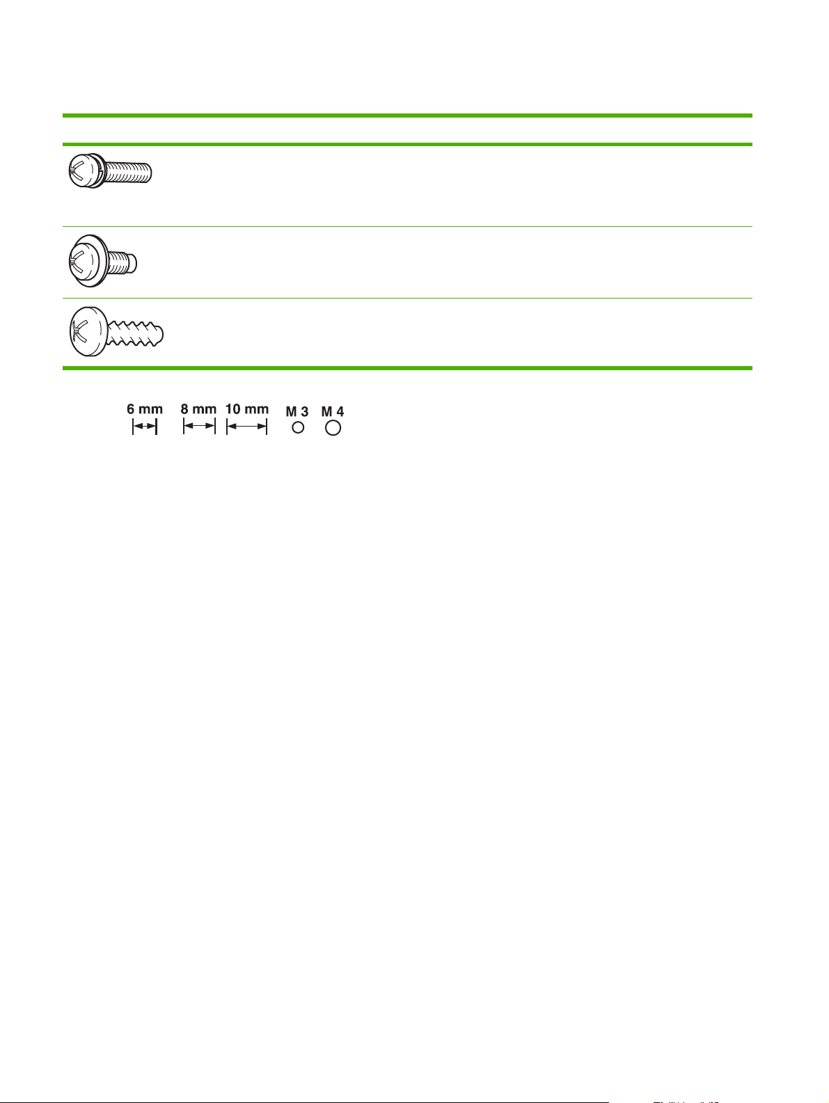
Types of screws
Illustration Description Size Part Number Use
Screw with washer M3X8 XA9–1420–000CN Used to secure metal
Screw, RS M3X6
M3X10
Screw, tapping, truss
head
M4X10 XB4–7401–000CN Used to secure anything
XA9–1499–000CN Used to secure metal to
components to metal
components (for
example, a ground wire
to the frame)
metal
to plastic
74 Chapter 5 Removal and replacement ENWW
Page 87

Service approach
Printer repair normally begins by using the printer internal diagnostics and the following two-step
process:
1. Isolate the problem to the major system (for example, the network or server, or the printer).
2. Troubleshoot the problem by using the procedures in chapter 6.
After a faulty part is located, the printer can usually be repaired at the assembly level by replacing
field-replaceable units (FRUs). Some mechanical assemblies might need to be repaired at the
subassembly level. Hewlett-Packard Company does not support replacement of components on the
printed circuit assembles.
Before performing service
Remove all media.
●
Unplug the power cable.
●
Place the product on an ESD mat (if available).
●
Remove the print cartridges.
●
Remove the tray 2 cassette.
●
After performing service
Return all media to the trays.
●
Plug in the power cable.
●
Reinstall the print cartridges.
●
Reinstall the tray 2 cassette.
●
ENWW Removal and replacement strategy 75
Page 88

Print cartridges
1. Open the front cover.
Figure 5-2 Remove the print cartridges (1 of 2)
2. Grasp the two blue handles on the print cartridge, and pull the cartridge out of the printer.
Figure 5-3 Remove the print cartridges (2 of 2)
76 Chapter 5 Removal and replacement ENWW
Page 89
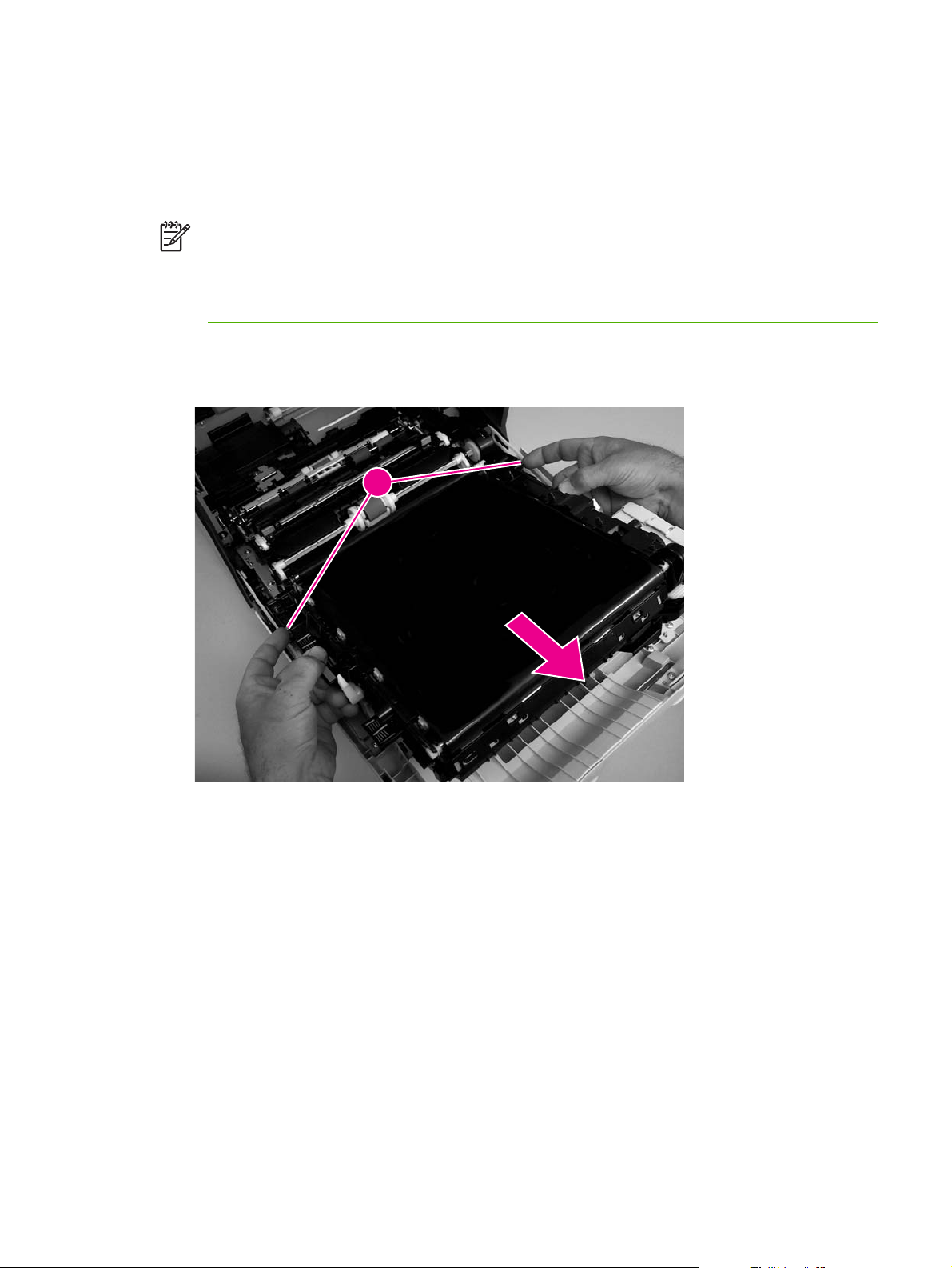
External doors, covers, and panels
Front cover
This part is called the front door in the user documentation and in chapter 1, “Product information.”
NOTE: The printer shown in the following procedure is a duplex model, and has a fan
mounted to the front-cover assembly. Simplex model printers do not have one.
NOTE: The ETB shown in this procedure is for the duplex model printer. The ETB for the
simplex model looks different.
1. Open the front cover.
2. Push in the two blue ETB latch buttons (callout 1) and pull the ETB out of the printer.
1
Figure 5-4 Remove the front cover (1 of 7)
ENWW External doors, covers, and panels 77
Page 90

3. Move the two ETB connectors (callout 2) to the raised position (as when the front cover is
closed).
2
Figure 5-5 Remove the front cover (2 of 7)
4. Lift the front cover slightly, and then gently pry the retainer arms off of the clips.
Figure 5-6 Remove the front cover (3 of 7)
78 Chapter 5 Removal and replacement ENWW
Page 91
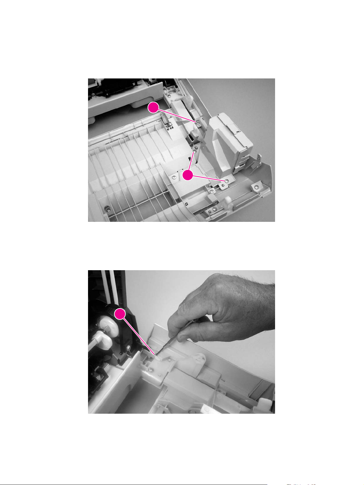
5. For duplex models, use the following procedure to remove the fan. For simplex models, skip to
the next step.
a. Remove two screws (callout 3) that secure the fan to the cover and one screw that secures
the wire-harness cover (callout 4).
4
3
Figure 5-7 Remove the front cover (4 of 7)
b. Use a small flatblade screwdriver to release the wire-harness-cover locking tab (callout 5)
and remove the wire-harness cover.
Remove the fan and set it next to the printer.
55
Figure 5-8 Remove the front cover (5 of 7)
ENWW External doors, covers, and panels 79
Page 92

6. Support the door and remove four screws (callout 6).
6
Figure 5-9 Remove the front cover (6 of 7)
80 Chapter 5 Removal and replacement ENWW
Page 93

7. Pull the front cover forward to remove it.
Figure 5-10 Remove the front cover (7 of 7)
TIP: Duplex model only: When you reinstall the duplex-fan wire-harness, make sure
that the wire-harness is clipped correctly to the door.
ENWW External doors, covers, and panels 81
Page 94
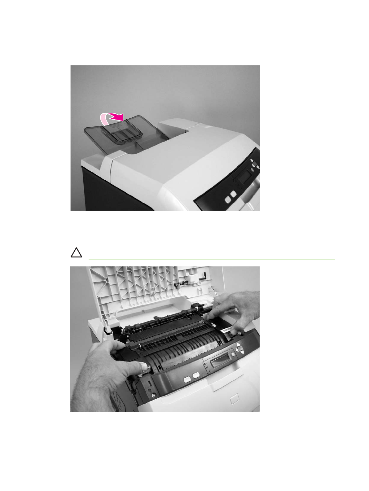
Upper cover (fuser door)
1. Rotate the output bin towards the front of the printer and remove it.
Figure 5-11 Remove the upper cover (1 of 5)
2. Open the upper cover, and then squeeze the two blue fuser-locking levers to release the fuser.
Rotate the fuser up and out of the printer.
CAUTION: The fuser might be hot. Wait for the fuser to cool before you remove it.
Figure 5-12 Remove the upper cover (2 of 5)
82 Chapter 5 Removal and replacement ENWW
Page 95

3. Support the upper cover and remove four screws (callout 1).
NOTE: The screw in the recessed area (see Figure 5-13 Remove the upper cover (3 of
5) on page 83) is longer than the other three mounting screws. Make sure to replace this
screw in the correct location when installing the upper cover.
1
Figure 5-13 Remove the upper cover (3 of 5)
4. Lift up slightly on the right of the upper cover and disconnect one connector (callout 2).
2
Figure 5-14 Remove the upper cover (4 of 5)
ENWW External doors, covers, and panels 83
Page 96

5. Lift the upper cover to remove it.
Figure 5-15 Remove the upper cover (5 of 5)
TIP: Make sure that the upper cover is seated correctly when it is reinstalled. Wire-
harness cables can block the cover alignment pin and become pinched or frayed when
the cover is fastened to the chassis.
84 Chapter 5 Removal and replacement ENWW
Page 97

Rear lower cover
1. Carefully flex the hinge bracket until you can dislodge the hinge pin. Move the rear lower cover
away from the bracket to remove it.
Figure 5-16 Remove the rear lower cover (1 of 2)
NOTE: Step 2 is only necessary if you are removing the rear upper cover or installing a
replacement hinge bracket.
2. Remove one screw (callout 1), and then remove the hinge bracket (callout 2).
1
2
Figure 5-17 Remove the rear lower cover (2 of 2)
ENWW External doors, covers, and panels 85
Page 98
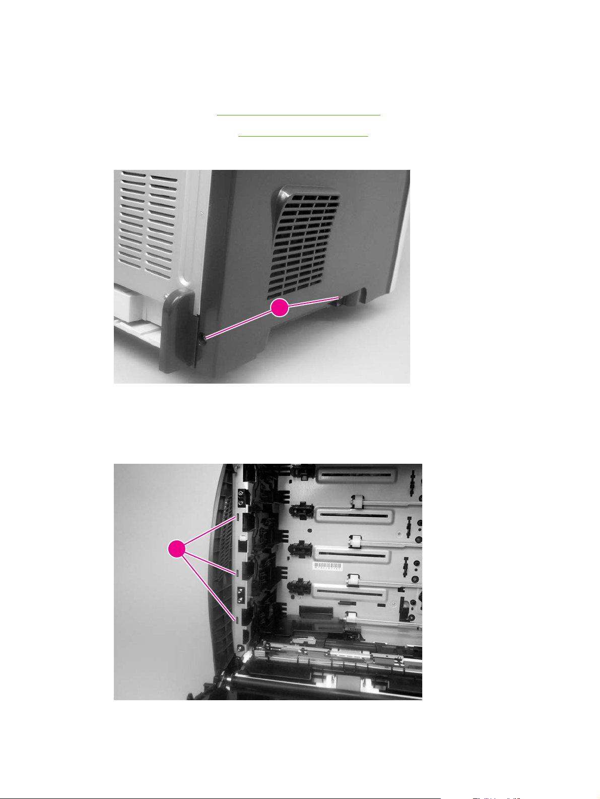
Left cover
1. Remove the following components:
Upper cover. See
●
Rear lower cover. See
●
2. Remove two screws (callout 1).
Figure 5-18 Remove the left cover (1 of 5)
Upper cover (fuser door) on page 82.
Rear lower cover on page 85.
1
3. Open the front cover.
4. Use a flatblade screwdriver to release the three locking tabs (callout 2) at the front of the left
cover.
2
Figure 5-19 Remove the left cover (2 of 5)
86 Chapter 5 Removal and replacement ENWW
Page 99

5. Release the locking tab (callout 3) at the upper front of the left cover.
3
Figure 5-20 Remove the left cover (3 of 5)
6. Release the two locking tabs at the rear of the left cover.
Figure 5-21 Remove the left cover (4 of 5)
ENWW External doors, covers, and panels 87
Page 100
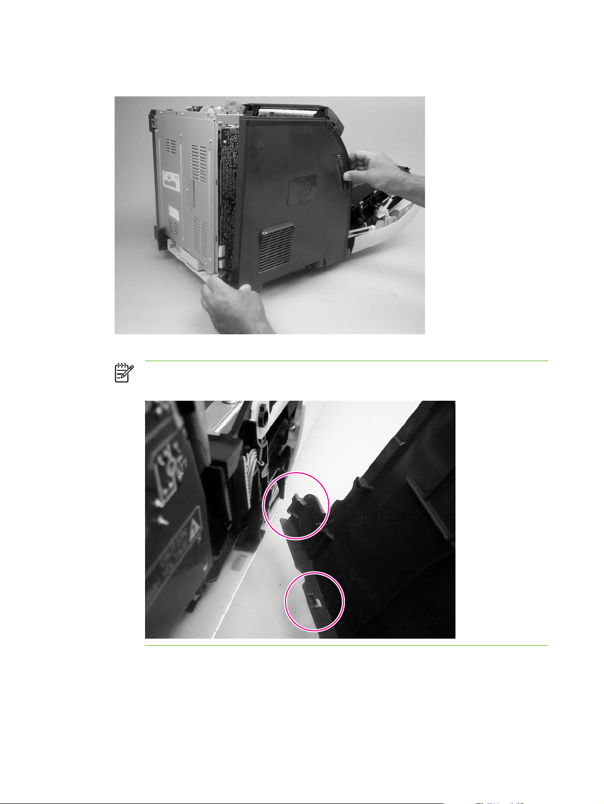
7. Rotate the back of the cover away from the printer, and then slide the cover to the rear to
disengage the two front locking tabs and release the cover.
Figure 5-22 Remove the left cover (5 of 5)
NOTE: This photograph shows the two front locking tabs low on the inside of the left
cover.
88 Chapter 5 Removal and replacement ENWW
 Loading...