

Page 1
HP Color LaserJet 2605, 2605dn, 2605dtn
Service Manual
Page 2

Page 3

HP Color LaserJet 2605, 2605dn, 2605dtn
Service Manual
Page 4

Copyright and License
FCC Class A Statement
Trademark Credits
© 2005 Copyright Hewlett-Packard
Development Company, L.P.
Reproduction, adaptation, or translation
without prior written permission is
prohibited, except as allowed under the
copyright laws.
The information contained in this document
is subject to change without notice.
The only warranties for HP products and
services are set forth in the express
warranty statements accompanying such
products and services. Nothing herein
should be construed as constituting an
additional warranty. HP shall not be liable
for technical or editorial errors or omissions
contained herein.
Q7821-90930
Edition 1, 12/2005
This equipment has been tested and found
to comply with the limits for a Class A
digital device, pursuant to Part 15 of the
FCC Rules. These limits are designed to
provide reasonable protection against
harmful interference when the equipment is
operated in a commercial environment.
This equipment generates, uses and can
radiate radio frequency energy and, if not
installed and used in accordance with the
instruction manual, may cause harmful
interference to radio communications.
Operation of this equipment in a residential
area is likely to cause harmful interference,
in which case the user will be required to
correct the interference at his own
expense. The end user of this product
should be aware that any changes or
modifications made to this equipment
without the approval of Hewlett-Packard
could result in the product not meeting the
Class A limits, in which case the FCC
could void the user’s authority to operate
the equipment.
Adobe Photoshop® and PostScript® are
trademarks of Adobe Systems Incorporated.
CorelDRAW™ is a trademark or registered
trademark of Corel Corporation or Corel
Corporation Limited.
Microsoft®, Windows®, and Windows NT®
are U.S. registered trademarks of Microsoft
Corporation.
Netscape™ and Netscape Navigator™ are
U.S. trademarks of Netscape
Communications Corporation.
TrueType™ is a U.S. trademark of Apple
Computer, Inc.
ENERGY STAR® and the ENERGY STAR
logo® are U.S. registered marks of the
United States Environmental Protection
Agency. Details on the proper use of the
marks are explained in the "Guidelines for
Proper use of the ENERGY STAR® Name
and International Logo."
Page 5

Table of contents
1 Printer basics
Printer configurations ............................................................................................................................. 2
HP Color LaserJet 2605 printer ............................................................................................ 2
HP Color LaserJet 2605dn printer ........................................................................................ 2
HP Color LaserJet 2605dtn printer ....................................................................................... 3
Printer features ...................................................................................................................................... 4
Walkaround ............................................................................................................................................ 6
Software ................................................................................................................................................. 8
Software and supported operating systems ......................................................................... 8
Print-media specifications ...................................................................................................................... 9
General guidelines ................................................................................................................ 9
Paper and print media ........................................................................................................... 9
Printing and storage environment ....................................................................................... 10
Envelopes ........................................................................................................................... 10
Labels .................................................................................................................................. 12
Transparencies ................................................................................................................... 13
HP LaserJet glossy paper and HP LaserJet Photo paper .................................................. 13
Letterhead or preprinted forms ........................................................................................... 13
HP LaserJet Tough paper ................................................................................................... 13
Custom-sized print media or cardstock .............................................................................. 14
Supported media weights and sizes ................................................................................... 14
2 Installation
Site preparation ................................................................................................................................... 18
Operating environment ....................................................................................................... 18
Minimum system requirements ........................................................................................... 19
Requirements for PC systems ........................................................................... 19
Requirements for Macintosh systems (non-PostScript) .................................... 19
Package contents ................................................................................................................................ 20
Install input devices ............................................................................................................................. 21
Installing Tray 3 (2605dtn) .................................................................................................. 21
Loading Tray 1 .................................................................................................................... 21
Loading Trays 2 and 3 ........................................................................................................ 23
3 Managing and maintenance
Control panel menus ........................................................................................................................... 30
Using the control panel menus ........................................................................................... 30
Control panel menu map .................................................................................................... 30
Managing supplies ............................................................................................................................... 32
ENWW iii
Page 6

Supplies life ......................................................................................................................... 32
Checking and ordering supplies ......................................................................................... 32
To check status and order using the control panel ............................................ 32
To check and order supplies using HP ToolboxFX ........................................... 32
To check and order using HP Web Jetadmin .................................................... 33
Storing supplies .................................................................................................................. 33
Replacing and recycling supplies ....................................................................................... 33
HP policy on non-HP supplies ............................................................................................ 33
Resetting the printer for non-HP supplies .......................................................... 33
HP anti-counterfeit website ................................................................................................. 34
Cleaning the printer ............................................................................................................................. 35
To remove toner build-up .................................................................................................... 35
To clean the paper path using HP ToolboxFX ................................................................... 37
Cartridge out override .......................................................................................................................... 38
Configuration ....................................................................................................................... 38
On-going operation ............................................................................................................. 38
Calibrating the printer .......................................................................................................................... 39
To calibrate the printer at the printer .................................................................................. 39
To calibrate the printer from the HP ToolboxFX ................................................................. 39
Managing the printer ............................................................................................................................ 40
Device pages and reports ................................................................................................... 40
Demo page ......................................................................................................... 40
Configuration page ............................................................................................. 40
Supplies Status page ......................................................................................... 41
Networking page ................................................................................................ 43
Fonts pages ........................................................................................................ 43
Usage page ........................................................................................................ 43
Menu map ........................................................................................................................... 43
HP ToolboxFX ..................................................................................................................... 44
To view HP ToolboxFX ...................................................................................... 44
Status ................................................................................................................. 45
Event log ............................................................................................ 45
Alerts .................................................................................................................. 46
Set up status alerts ............................................................................ 46
Set up e-mail alerts ........................................................................... 46
Help .................................................................................................................... 46
Device settings ................................................................................................... 47
Device information ............................................................................. 47
Paper handling .................................................................................. 48
Printing .............................................................................................. 48
PCL5e ................................................................................................ 48
PostScript .......................................................................................... 49
Print quality ........................................................................................ 49
Print density ....................................................................................... 49
Paper types ....................................................................................... 50
Memory card (HP Color LaserJet 2605dtn) ...................................... 50
System setup ..................................................................................... 51
Service ............................................................................................... 51
Network settings ................................................................................................. 51
Using the embedded Web server ....................................................................................... 51
iv ENWW
Page 7

4 Operational theory
Engine control system ......................................................................................................................... 56
Image formation system ...................................................................................................................... 59
Pickup and feed system ...................................................................................................................... 69
Service-only tools (SERVICE ONLY) .................................................................................................. 80
To access the embedded Web server using a network connection .................. 52
Information tab ................................................................................................... 52
Settings tab ........................................................................................................ 53
Networking tab ................................................................................................... 53
Other links in HP ToolboxFX .............................................................................. 53
Basic sequence of operation .............................................................................................. 56
Power-on sequence ............................................................................................................ 57
Motors and fans .................................................................................................................. 57
Main motor failure detection ............................................................................... 58
Fan motor failure detection ................................................................................ 58
Image formation process .................................................................................................... 61
Latent image formation ...................................................................................... 62
Laser/scanner system ........................................................................................ 63
Developing stage ................................................................................................................ 63
Print cartridge ..................................................................................................... 64
Transfer belt (ETB) ............................................................................................. 65
Transfer stage ..................................................................................................................... 66
Separation stage ................................................................................................................. 67
Fusing stage ....................................................................................................................... 67
Manual feed slot pickup mechanism .................................................................................. 71
Paper feed mechanism ....................................................................................................... 71
Skew correction by the registration shutter ........................................................................ 71
Jam detection ...................................................................................................................... 72
Solenoid, motor, and fan locations ..................................................................................... 73
Printed circuit assembly locations ....................................................................................... 73
250-sheet tray solenoid and printed circuit locations ......................................................... 74
Duplexing mechanism ........................................................................................................ 75
General timing chart ............................................................................................................ 80
Printer calibration ................................................................................................................ 81
5 Removal and replacement
Overview .............................................................................................................................................. 84
Service approach ................................................................................................................................. 85
Pre-service procedures ....................................................................................................... 85
Removal and replacement procedures ............................................................................................... 86
Print cartridge replacement ................................................................................................. 86
ETB removal and replacement ........................................................................................... 89
Fuser removal and replacement ......................................................................................... 97
Formatter removal and replacement ................................................................................ 105
DC controller removal and replacement ........................................................................... 108
Separation assembly removal and replacement .............................................................. 111
Paper-pickup roller removal and replacement .................................................................. 112
Control panel removal and replacement ........................................................................... 114
Memory-card assembly removal and replacement .......................................................... 119
ENWW v
Page 8

6 Troubleshooting
Troubleshooting process ................................................................................................................... 134
Control-panel messages .................................................................................................................... 136
Clearing jams ..................................................................................................................................... 142
E-Label reader guide pin damage ..................................................................................................... 150
Print problems .................................................................................................................................... 151
Functional tests (SERVICE ONLY) ................................................................................................... 163
Service mode functions (SERVICE ONLY) ....................................................................................... 164
Troubleshooting tools ........................................................................................................................ 166
Duplexing drive unit removal and replacement ................................................................ 124
Duplexing-driver PCA removal and replacement ............................................................. 129
Troubleshooting checklist ................................................................................................. 134
Alert and warning messages ............................................................................................ 136
Status-log messages ........................................................................................................ 140
Where to look for jams ...................................................................................................... 142
To clear jams from inside the printer ................................................................................ 143
To clear jams from the duplex area (HP Color LaserJet 2605dn and 2605dtn models
only) .................................................................................................................................. 144
To clear jams from the top bin (HP Color LaserJet 2605) ................................................ 146
To clear jams from the top output area (HP Color LaserJet 2605dn and 2605dtn
models only) ...................................................................................................................... 147
To clear jams from Tray 2 or optional Tray 3 .................................................................... 149
Printed image quality problems ........................................................................................ 151
Improving print quality ...................................................................................... 151
Paper Types menu .......................................................................... 151
Print Modes menu ........................................................................... 151
Print quality menu ............................................................................ 152
Understanding print-quality settings ................................................................. 153
To temporarily change print-quality settings ................................... 153
To change print-quality settings for all future jobs .......................... 153
Identifying and correcting printed image defects ............................................. 153
Print-quality checklist ....................................................................... 154
General print quality issues .............................................................................. 154
Solving issues with color documents ............................................................... 158
Paper handling issues ...................................................................................................... 160
Wrong size/type media ..................................................................................... 160
Cannot select a tray or feature to use .............................................................. 161
Performance problems ..................................................................................................... 161
Engine-test print ................................................................................................................ 163
Cold reset .......................................................................................................................... 164
NVRAM initializer .............................................................................................................. 164
Super NVRAM initializer ................................................................................................... 164
Restoring page counts and serial number ........................................................................ 165
Cleaning the ETB .............................................................................................................. 165
Printer pages and reports ................................................................................................. 166
Demo page ....................................................................................................... 166
Configuration page ........................................................................................... 167
Supplies Status page ....................................................................................... 167
Fuser cleaning page ......................................................................................... 167
vi ENWW
Page 9

Print quality troubleshooting pages .................................................................. 167
Status log ......................................................................................................... 167
Event log .......................................................................................................... 168
Service menu .................................................................................................................... 169
Service menu settings ...................................................................................... 169
Restoring the factory-set defaults .................................................................... 169
To restore the factory-set defaults .................................................. 169
Secondary service menu .................................................................................................. 169
HP ToolboxFX ................................................................................................................................... 171
HP ToolboxFX ................................................................................................................... 171
To view HP ToolboxFX .................................................................................... 171
Troubleshooting tab ......................................................................................... 171
Print quality troubleshooting pages .................................................................................. 171
Printer calibration .............................................................................................................. 171
Cleaning page ................................................................................................................... 172
Configuration page ............................................................................................................ 172
Diagnostic resources ......................................................................................................................... 173
Reports menu ................................................................................................................... 173
Network/Web diagnostics tools ......................................................................................... 173
Repetitive-image-defect ruler ............................................................................................................ 174
Firmware and software updates ........................................................................................................ 175
7 Parts and diagrams
Overview ............................................................................................................................................ 178
Assembly locations ............................................................................................................................ 182
Covers ............................................................................................................................................... 188
Internal assemblies ............................................................................................................................ 192
Input devices ...................................................................................................................................... 210
Diagrams ........................................................................................................................................... 222
Alphabetical parts list ......................................................................................................................... 223
Numerical parts list ............................................................................................................................ 226
Appendix A Specifications
Printer specifications ......................................................................................................................... 230
Appendix B Service and support
Hewlett-Packard limited warranty statement ..................................................................................... 234
Print Cartridge Limited Warranty Statement ..................................................................................... 235
HP Customer Care ............................................................................................................................ 236
Availability of support and service ..................................................................................................... 238
HP Care Pack™ Services and Service Agreements ........................................................ 238
Repacking the printer ........................................................................................................................ 239
To repack the printer ......................................................................................................... 239
Service information form .................................................................................................................... 240
Appendix C Regulatory information
Introduction ........................................................................................................................................ 242
FCC regulations ................................................................................................................................. 243
Environmental Product Stewardship program ................................................................................... 244
ENWW vii
Page 10

Protecting the environment ............................................................................................... 244
Ozone production .............................................................................................................. 244
Power consumption .......................................................................................................... 244
HP LaserJet printing supplies ........................................................................................... 244
Disposal of waste equipment by users in private households in the European Union .... 245
Material safety data sheet ................................................................................................. 246
Declaration of conformity ................................................................................................................... 247
Country/region-specific safety statements ........................................................................................ 248
Laser safety statement ..................................................................................................... 248
Canadian DOC statement ................................................................................................. 248
Korean EMI statement ...................................................................................................... 248
VCCI statement (Japan) ................................................................................................... 248
Finnish laser statement ..................................................................................................... 249
Index .................................................................................................................................................................. 251
viii ENWW
Page 11

1 Printer basics
This section provides information about the following topics:
Printer configurations
●
●
Printer features
Walkaround
●
Software
●
Print-media specifications
●
ENWW 1
Page 12
Printer configurations
Thank you for purchasing the HP Color LaserJet 2605 Series printer. This printer is available in the
configurations described below.
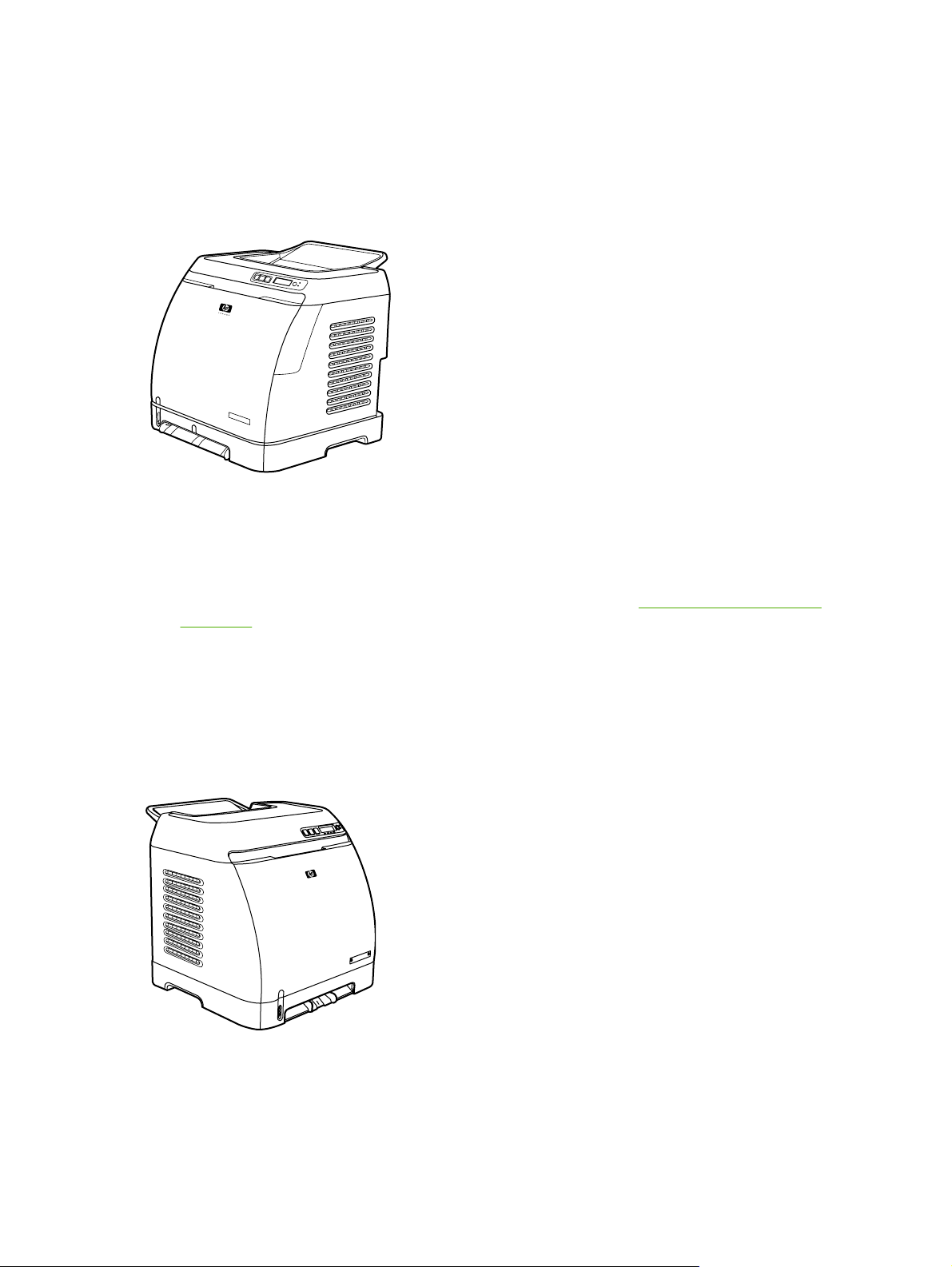
HP Color LaserJet 2605 printer
The HP Color LaserJet 2605 printer is a four-color laser printer that prints 10 pages per minute (ppm)
in color and 12 ppm in monochrome (black and white).
● Trays. The printer comes with a single sheet priority feed slot (Tray 1) and a universal tray
(Tray 2) that holds up to 250 sheets of various paper types and sizes or 10 envelopes. It
supports an optional 250-sheet paper tray (optional Tray 3). See
on page 9 for more information.
Print-media specifications
Connectivity. The printer provides a Hi-Speed USB 2.0 port for connectivity.
●
Memory. The printer contains 64 megabytes (MB) of synchronous dynamic random access
●
memory (SDRAM). To allow for memory expansion, the printer has one DIMM slot that accepts
256 MB RAM. This printer can support up to 320 MB of memory.
HP Color LaserJet 2605dn printer
2 Chapter 1 Printer basics ENWW
Page 13
The HP Color LaserJet 2605dn printer is a four-color laser printer that prints 10 ppm in color and
12 ppm in monochrome (black and white).
● Trays. The printer comes with a single sheet priority feed slot (Tray 1) and a universal tray (Tray
2) that holds up to 250 sheets of various paper types and sizes or 10 envelopes. It supports an
optional 250-sheet paper tray (optional Tray 3). See
more information.
● Connectivity. The printer provides a USB port for connectivity and an HP built-in internal print
server for connecting to a 10/100Base-T network.
● Memory. The printer contains 64 megabytes (MB) of synchronous dynamic random access
memory (SDRAM). To allow for memory expansion, the printer has one DIMM slot that accepts
256 MB RAM. This printer can support up to 320 MB of memory.
● Print on Both Sides. The printer can automatically print on both sides.
Print-media specifications on page 9 for
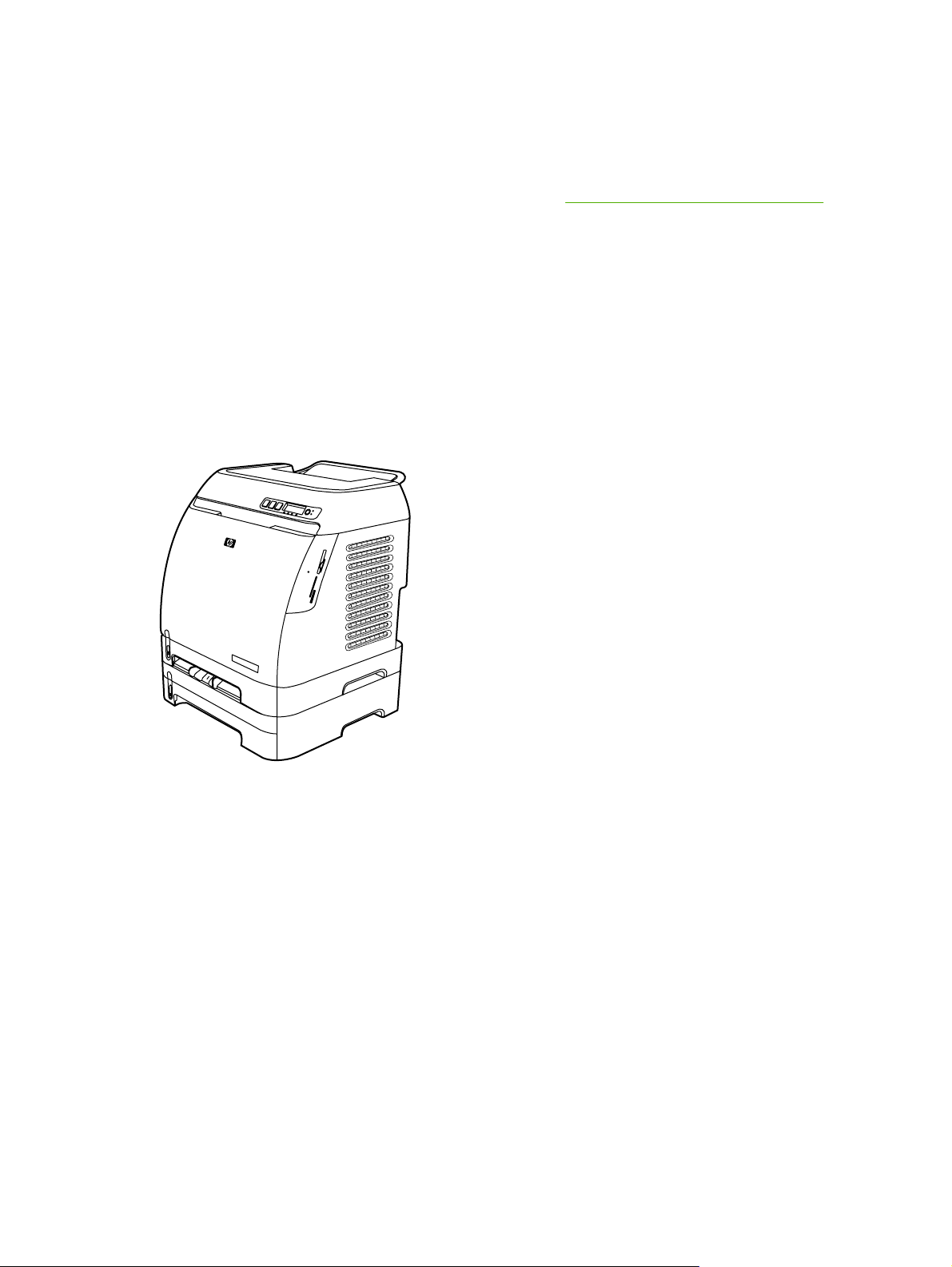
HP Color LaserJet 2605dtn printer
The HP Color LaserJet 2605dtn printer includes the features of the HP Color LaserJet 2605dn
printer, but has an additional 250-sheet paper tray (Tray 3) and four memory card slots.
ENWW Printer configurations 3
Page 14

Printer features
Feature HP Color LaserJet 2605 Series printer
Color printing ● Provides laser printing in full color by using the four
Fast print speed
Excellent print quality ●
Ease of use ● Few supplies to order. Supplies are easy to install.
Flexible paper handling
process colors: cyan, magenta, yellow, and black
(CMYK).
● Prints in black on A4/letter paper up to 12 ppm. Prints
in color on A4/letter at 10 ppm.
ImageREt 2400 provides 2400 dpi equivalent-color
quality through a multilevel printing process.
● True 600 by 600 dots per inch (dpi) text and graphics.
● Adjustable settings to optimize print quality.
The HP UltraPrecise print cartridge has a finer toner
●
formulation that provides sharper text and graphics.
Convenient access to printer information and settings
●
by using the HP ToolboxFX software.
● Convenient access to all supplies and to the paper path
through the front door.
Trays 1 and 2 for letterhead, envelopes, labels,
●
transparencies, custom-sized media, postcards,
HP LaserJet glossy paper, HP LaserJet Tough paper,
heavy paper, and HP Laser Photo paper.
● A 125-sheet top output bin.
● Print on both sides manually.
Print on both sides automatically (HP Color LaserJet
●
2605dn and HP Color LaserJet 2605dtn models only).
PostScript® (PS) level 3 emulation language and fonts
Interface connections ●
Energy savings ● The printer automatically conserves electricity by
Economical printing ● N-up printing (printing more than one page on a sheet)
Includes 35 built-in PS language fonts.
Hi-Speed USB port.
● The HP Color LaserJet 2605dn and 2605dtn printers
includes an HP built-in internal print server for
connecting to a 10/100Base-T network.
substantially reducing power consumption when it is
not printing.
As an ENERGY STAR® partner, Hewlett-Packard
●
Company has determined that this product meets
ENERGY STAR® guidelines for energy efficiency.
ENERGY STAR® is a U.S. registered service mark of
the United States Environmental Protection Agency.
and Printing on Both Sides features save paper.
4 Chapter 1 Printer basics ENWW
Page 15

Feature HP Color LaserJet 2605 Series printer
Supplies
Accessibility ● Online user guide that is compatible with text screen-
Expandability ● Optional Tray 3 (standard on HP Color LaserJet
Memory card slots (HP Color LaserJet 2605dtn only)
A Supplies Status page with print cartridge gauges that
●
show the supply levels that remain. For HP supplies
only.
● No-shake cartridge design.
Authentication for HP print cartridges.
●
Enabled supplies-ordering capability.
●
readers.
● All doors and covers can be opened by using one hand.
2605dtn). This 250-sheet universal tray reduces how
often you have to add paper to the printer. Only one
additional 250-sheet tray can be installed on the printer.
● Optional HP Jetdirect external print server for
connecting to a network.
● One DIMM slot for adding memory and fonts.
The following memory cards are supported:
CompactFlash
●
Memory Stick and Memory Stick PRO
●
● MultiMedia
● Secure Digital (SD)
SmartMedia
●
xD
●
ENWW Printer features 5
Page 16
Walkaround
The following illustrations identify the locations and names of key components of this printer.
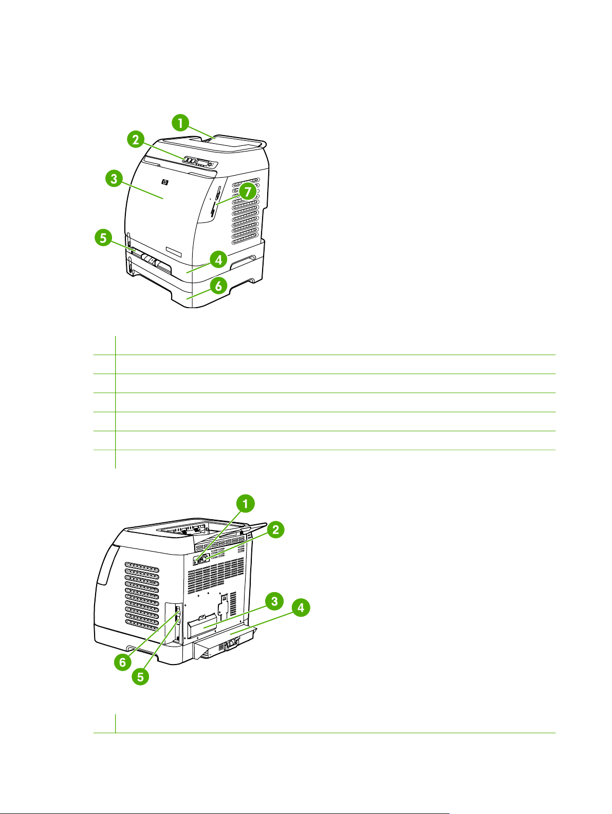
Figure 1-1 Front view (HP Color LaserJet 2605dtn shown)
1 Output bin
2 Printer control panel
3 Front door
4 Tray 2 (250 sheets)
5 Tray 1 (single-sheet priority feed slot)
6 Tray 3 (optional; 250 sheets)
7 Memory card slots (HP Color LaserJet 2605dtn only)
Figure 1-2 Back and side view
1 Power switch
6 Chapter 1 Printer basics ENWW
Page 17
2 Power connection
3 DIMM access door
4 Dust cover
5 HP built-in internal print server for connecting to a 10/100Base-T network (HP Color LaserJet 2605dn and 2605dtn)
6 USB connection
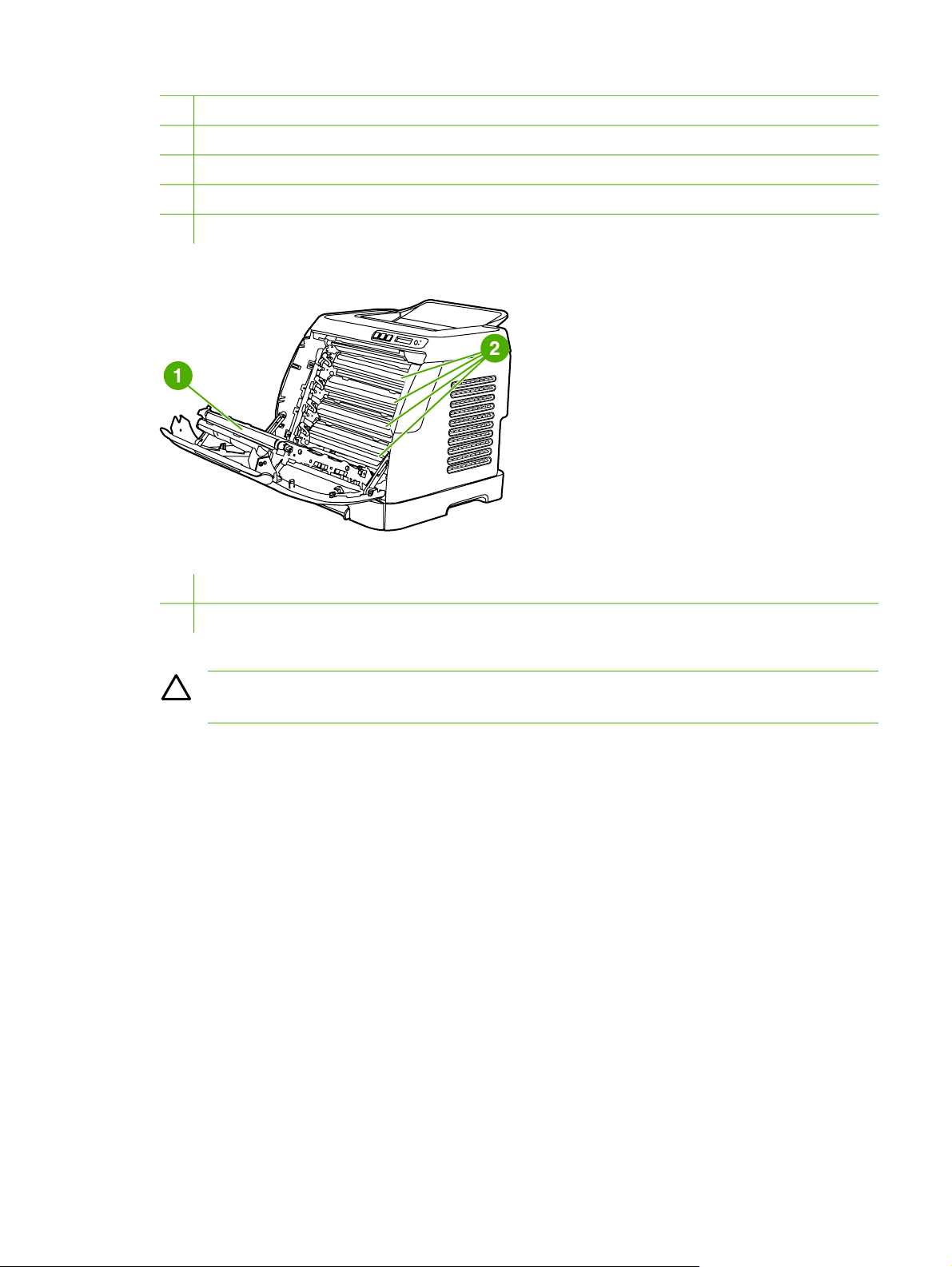
Figure 1-3 Front view, cartridge door open
1 Transfer belt (ETB)
2 Print cartridges
CAUTION Do not place anything on the transfer belt, which is located on the inside of the
front door. Otherwise, the printer may be damaged, adversely affecting print quality.
ENWW Walkaround 7
Page 18

Software
Software and supported operating systems
For easy printer setup and access to the full range of printer features, HP strongly recommends that
you install the software that is provided. Not all software is available in all languages. See the Getting
Started Guide for installation instructions, and see the Readme file for the latest software information.
The most recent drivers, additional drivers, and other software are available from the Internet and
other sources. If you do not have access to the Internet, see
The printer supports the following operating systems:
● Microsoft® Windows® 98 Second Edition, Windows Millennium Edition (Me), and Windows®
●
●
The following tables list the software that is available for your operating system.
Table 1-1 HP Color LaserJet 2605 Series printer software
HP Customer Care on page 236.
Server 2003 (Add Printer installation)
Microsoft® Windows® 2000 and Windows XP
Macintosh OS X v10.2 and later
Feature Windows 98 Second
Windows Installer
PCL printer driver
PS printer driver
HP Web Jetadmin software
HP ToolboxFX software
HP imaging software
Macintosh Installer
Macintosh printer drivers
Edition, Me, and
Server 2003
Windows 2000 and XP Macintosh OS X v10.2 and
later
8 Chapter 1 Printer basics ENWW
Page 19

Print-media specifications
This section contains information about specifications for the quality of print media, guidelines for
print media usage, and guidelines for print media storage.
General guidelines
Some print media might meet all of the guidelines in this manual and still not produce satisfactory
results. This problem might be the result of improper handling, unacceptable temperature and
humidity levels, or other variables over which Hewlett-Packard has no control.
Before purchasing large quantities of print media, always test a sample and make sure that the print
media meets the requirements specified in this user guide and in the HP LaserJet Printer Family
Print Media Guide.
CAUTION Using print media that does not meet HP specifications can cause problems for
the printer, requiring repair. This repair is not covered by the Hewlett-Packard warranty or
service agreements.
CAUTION Use only paper designed for laser printers. Paper for inkjet printers may damage
the printer.
This printer accepts a variety of media, such as cut-sheet paper (including up to 100% recycled-fibercontent paper), envelopes, labels, transparencies, HP LaserJet glossy paper, HP LaserJet Tough
paper, HP LaserJet Photo paper, and custom-size paper. Properties such as weight, composition,
grain, and moisture content are important factors that affect printer performance and output quality.
Print media that does not meet the guidelines outlined in this manual can cause the following
problems:
Poor print quality
●
Increased jams
●
● Premature wear on the printer, requiring repair
Paper and print media
Print-media specifications for the HP LaserJet 2605 Series printer are listed in Table 1-2 Print-media
specifications on page 9.
Table 1-2 Print-media specifications
Category Specifications
Acid content 5.5 pH to 8.0 pH
Caliper 0.094 to 0.18 mm (3.0 to 7.0 mils)
Curl in ream Flat within 5 mm (0.02 inch)
Cut-edge conditions Cut with sharp blades with no visible fray
Fusing compatibility Must not scorch, melt, offset, or release hazardous
Grain Long Grain
emissions when heated to 210°C (410°F) for 0.1 second
ENWW Print-media specifications 9
Page 20

Table 1-2 Print-media specifications (continued)
Category Specifications
Moisture content 4% to 6% by weight
Smoothness 100 to 250 Sheffield
For complete print-media specifications for all HP LaserJet printers, see the HP LaserJet Printer
Family Print Media Guide. To download the guide in PDF format, go to
ljpaperguide.
http://www.hp.com/support/
Printing and storage environment
Ideally, the printing and media-storage environment should be at or near room temperature, and not
too dry or too humid. Remember that paper is hygroscopic; it absorbs and loses moisture rapidly.
Heat causes the moisture in paper to evaporate, while cold causes it to condense on the sheets.
Heating systems and air conditioners remove most of the humidity from a room. As paper is opened
and used, it loses moisture, causing streaks and smudging. Humid weather or water coolers can
cause the humidity to increase in a room. As paper is opened and used it absorbs any excess
moisture, causing light print and dropouts. Also, as paper loses and gains moisture it can distort. This
issue can cause jams.
As a result, paper storage and handling are as important as the paper-making process itself. Paper
storage environmental conditions directly affect the feed operation and print quality.
Care should be taken not to purchase more paper than can be easily used in a short time (about
three months). Paper stored for long periods can experience heat and moisture extremes, which can
cause damage. Planning is important to prevent damage to a large supply of paper.
Unopened paper in sealed reams can remain stable for several months before use. Opened
packages of paper have more potential for environmental damage, especially if they are not wrapped
with a moisture-proof barrier.
The media-storage environment should be properly maintained to ensure optimum printer
performance. The recommended condition is 20° to 24°C (68° to 75°F), with a relative humidity of
45% to 55%. The following guidelines should be helpful when evaluating the paper's storage
environment:
Print media should be stored at or near room temperature.
●
The air should not be too dry or too humid (to moderate the hygroscopic properties of paper).
●
● The best way to store an opened ream of paper is to rewrap it tightly in its moisture-proof
wrapping. If the printer environment is subject to extremes, unwrap only the amount of paper to
be used during the day's operation to prevent unwanted moisture changes.
● Avoid storing paper and print media near heating and air conditioning vents or near windows
and doors that are frequently open.
Envelopes
Envelopes can be printed from Tray 1 or Tray 2. Select the type of envelope that you are using from
the Print dialog box or the printer driver.
10 Chapter 1 Printer basics ENWW
Page 21

In your program, set the margins for the envelope. The following table gives typical address margins
for a commercial #10 or DL envelope.
Type of address Top margin Left margin
Return address 15 mm (0.6 inch) 15 mm (0.6 inch)
Delivery address 51 mm (2 inches) 89 mm (3.5 inches)
For the best print quality, position margins no closer than 15 mm (0.6 inch) from the edges of
●
the envelope.
Avoid printing over the area where the envelope seams meet.
●
Envelope storage
Proper storage of envelopes helps contribute to print quality. Envelopes should be stored flat. If air is
trapped in an envelope and creates an air bubble, then the envelope might wrinkle during printing.
Envelope construction
Envelope construction is critical. Envelope fold lines can vary considerably, not only between
manufacturers, but also within a box from the same manufacturer. Successful printing on envelopes
depends upon the quality of the envelopes. When selecting envelopes, consider the following
components:
●
Weight: The weight of the envelope paper should not exceed 90 g/m
2
(24 lb) or jamming might
occur.
● Construction: Before printing, envelopes should lie flat with less than 6 mm (0.25 inch) curl,
and should not contain air.
● Condition: Envelopes should not be wrinkled, nicked, stuck together, or otherwise damaged.
Never use envelopes that have clasps, snaps, windows, coated linings, self-stick adhesives, or
other synthetic materials.
● Temperature: Use envelopes that are compatible with the heat and pressure of the printer. This
printer's fusing temperature is 210°C (410°F).
● Size: Use only envelopes that are within the following size ranges.
Tray Minimum Maximum
Tray 1 or Tray 2 76 x 127 mm (3 x 5 inches) 216 x 356 mm
(8.5 x 14 inches)
Envelopes with double side-seams
Double side-seam construction has vertical seams at both ends of the envelope rather than diagonal
seams. This style might be more likely to wrinkle. Be sure the seam extends all the way to the corner
of the envelope as indicated in the following illustration.
ENWW Print-media specifications 11
Page 22

1
2
1 Acceptable
2 Unacceptable
Envelopes with adhesive strips or flaps
Envelopes with a peel-off adhesive strip or with more than one flap that folds over to seal must use
adhesives that are compatible with the heat and pressure in the printer. The extra flaps and strips
might cause wrinkling, creasing, or even jams and might damage the fuser.
CAUTION Failure to follow the guidelines above can result in jams.
For instructions on loading envelopes, see Loading Tray 1 on page 21 or Loading Trays 2 and 3
on page 23.
Labels
Select the type of label that you are using from the Print dialog box or the printer driver.
CAUTION To avoid damaging the printer, use only labels that are recommended for laser
printers. To prevent serious jams, always use Tray 1 or Tray 2 to print on labels. Never print
on the same sheet of labels more than once or print on a partial sheet of labels.
When selecting labels, consider the quality of each component:
Adhesives: The adhesive material should be stable at 210°C (410°F), which is the printer
●
fusing temperature.
● Arrangement: Only use labels with no exposed backing between them. Labels can peel off
sheets with spaces between the labels, causing serious jams.
● Curl: Before printing, labels must lie flat with no more than 13 mm (0.5 inch) of curl in any
direction.
● Condition: Do not use labels that have wrinkles, bubbles, other indications of separation, or are
damaged in any way.
For instructions on loading labels, see
on page 23.
Loading Tray 1 on page 21 or Loading Trays 2 and 3
12 Chapter 1 Printer basics ENWW
Page 23

Transparencies
● Use only Tray 1 or Tray 2 to print on transparencies. Select Transparencies from the Print
dialog box or the printer driver.
● The printer supports printing on color transparencies. Use only transparencies that are
recommended for use in laser printers.
● Place transparencies on a flat surface after removing them from the printer.
Transparencies that are used in the printer must be able to withstand 210°C (410°F), which is
●
the printer fusing temperature.
CAUTION To avoid damage to the printer, use only transparencies that are recommended
for use in laser printers.
Transparent print media that is not designed for LaserJet printing will melt in the printer, and
will damage the printer.
HP LaserJet glossy paper and HP LaserJet Photo paper
● Handle HP LaserJet glossy paper and HP LaserJet Photo paper by the edges. Oil from your
fingers that is deposited on HP LaserJet glossy paper and HP LaserJet Photo paper can cause
print-quality problems.
● Use only HP LaserJet glossy paper and HP LaserJet Photo paper with this printer. HP products
are designed to work together for optimum printing results.
Letterhead or preprinted forms
Avoid using raised or embossed letterhead.
●
Avoid using letterhead that is printed with low-temperature inks, such as those used in some
●
types of thermography.
The printer uses heat and pressure to fuse toner to the print media. Make sure that any colored
●
paper or preprinted forms use inks that are compatible with this fusing temperature (210°C (410°
F) for 0.1 second).
For instructions on loading letterhead, see
on page 23.
Loading Tray 1 on page 21 and Loading Trays 2 and 3
HP LaserJet Tough paper
When printing on HP LaserJet Tough paper, follow these guidelines:
Handle HP LaserJet Tough paper by the edges. Oil from your fingers that is deposited on
●
HP LaserJet Tough paper can cause print-quality problems.
Use only HP LaserJet Tough paper with this printer. HP products are designed to work together
●
for optimum printing results.
ENWW Print-media specifications 13
Page 24

Custom-sized print media or cardstock
● Postcards, 3 x 5-inch (index) cards, and other custom-sized print media can be printed on from
Tray 1, Tray 2, or optional Tray 3. The minimum size is 76 x 127 mm (3 x 5 inches) and the
maximum size is 216 x 356 mm (8.5 x 14 inches). See
more information.
● Always insert the short edge first into Tray 1, Tray 2, or optional Tray 3. To print in landscape
mode, make this selection through your program. Inserting the media long-edge-first might
cause a jam.
In your program, set margins at least 6.4 mm (0.25 inch) away from the edges of the print media.
●
Print-media specifications on page 9 for
For instructions on loading paper, see
on page 23.
Loading Tray 1 on page 21 and Loading Trays 2 and 3
Supported media weights and sizes
This section contains information about the sizes, weights, and capacities of paper and other print
media that each tray supports.
14 Chapter 1 Printer basics ENWW
Page 25

Table 1-3 Tray 1 and Tray 2 specifications
Tray 1 and Tray 2
Dimensions
1
Paper Minimum: 76 x 127 mm
(3 x 5 inches)
Maximum: 216 x 356 mm
(8.5 x 14 inches)
HP LaserJet glossy paper and
HP LaserJet Photo paper
4
HP Premium Cover paper
Same as the preceding listed
minimum and maximum sizes.
4
Transparencies and opaque film
3
Labels
Weight Capacity
60 to 163 g/m2 (16 to 43 lb)
Up to 176 g/m
2
(47 lb) for
postcards
75 to 220 g/m2 (20 to 58 lb)
Single sheet of 75 g/m2 (20 lb)
paper for Tray 1
Up to 250 sheets for Tray 2
Single sheet of HP LaserJet
glossy paper or HP LaserJet
Photo paper for Tray 1
Up to 25 mm (0.99 inch) stack
height for Tray 2
200 g/m2 (53 lb)
Single sheet of HP Cover paper
for Tray 1
Up to 25 mm (0.99 inch) stack
height for Tray 2
Thickness: 0.10 to 0.13 mm
(3.9 to 5.1 mils)
Single sheet of transparency or
opaque film for Tray 1
Up to 50 sheets for Tray 2
Thickness: up to 0.23 mm (up
Single sheet of labels for Tray 1
to 9 mils)
Up to 25 mm (0.99 inch) stack
height for Tray 2
2
Envelopes
Up to 90 g/m2 (up to 24 lb)
Single envelope for Tray 1
Up to ten envelopes for Tray 2
1
The printer supports a wide range of standard and custom sizes of print media. Check the printer driver for supported sizes.
2
Capacity can vary depending on media weight and thickness, and environmental conditions.
4
Hewlett-Packard does not guarantee results when printing with other types of heavy paper.
3
Smoothness: 100 to 250 (Sheffield).
Table 1-4 Optional Tray 3 specifications
Optional Tray 3 (250-sheet
Dimensions
1
Weight
Capacity
tray)
Plain paper Minimum: 76 x 127 mm
60 to 163 g/m2 (16 to 43 lb)
Up to 200 sheets
(3 x 5 inches)
Maximum: 216 x 356 mm (8.5 x
14 inches)
1
The printer supports a wide range of standard and custom sizes of print media. Check the printer driver for supported sizes.
2
Capacity can vary depending on the media weight and thickness, and environmental conditions.
2
Table 1-5 Specifications for automatic 2-sided printing
Tray 1, Tray 2, and optional
Tray 3
Dimensions
1
Weight
Capacity
2
Paper Letter, A4, legal, 8.5 x 13 inches
60 to 105 g/m
2
(16 to 28 lb)
Single sheet for Tray 1
ENWW Print-media specifications 15
Page 26

Table 1-5 Specifications for automatic 2-sided printing (continued)
Tray 1, Tray 2, and optional
Tray 3
Dimensions
1
Weight
Capacity
2
Up to 250 sheets for Tray 2 and
optional Tray 3
HP LaserJet glossy paper Letter, A4
75 to 120 g/m2 (20 to 32 lb)
Single sheet for Tray 1
Up to 250 sheets for Tray 2 and
optional Tray 3
1
The printer supports a wide range of standard and custom sizes of print media. Check the printer driver for supported sizes.
2
Capacity can vary depending on the media weight and thickness, and environmental conditions.
16 Chapter 1 Printer basics ENWW
Page 27

2 Installation
This chapter contains information about the following topics:
Site preparation
●
●
Package contents
Install input devices
●
ENWW 17
Page 28
Site preparation
Below are recommendations for the printer location and placement.
Operating environment
The printer must be kept in a proper location to maintain the performance level that has been set at
the factory. In particular, be sure that the environment adheres to the specifications listed in this
chapter.
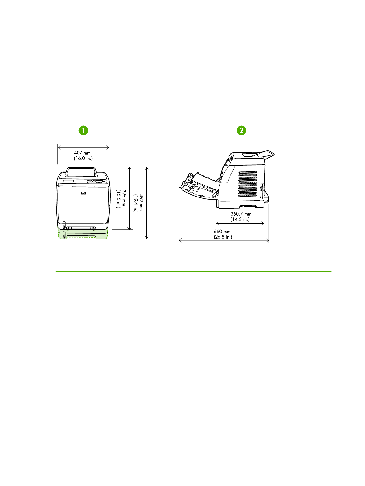
The printer must have 2 inches of space above and around it.
Figure 2-1 Printer dimensions
1 Front view
2 Side view
Make sure the printer is in a location that has the following:
● A well-ventilated, dust-free area
● A surface that will support up to 18 kg (40 lbs)
● A constant temperature and humidity (Do not install near water sources, humidifiers, air
conditioners, refrigerators, or other major appliances.)
● A hard, level surface (not more than a 2° angle)
Make sure to keep the printer away from the following:
● Direct sunlight, dust, open flames, or water
● Direct flow of exhaust from air ventilation systems
Magnets and devices that emit a magnetic field
●
18 Chapter 2 Installation ENWW
Page 29

Areas subject to vibration
●
● Walls or other objects. There must be enough space around the printer for proper access and
ventilation
Minimum system requirements
The minimum system requirements for the HP Color LaserJet 2605, 2605dn, and 2605dtn printers
are listed below:
● 150 MB of free hard disk space
CD-ROM drive
●
Available USB or network port
●
NOTE Networking is only available on Windows 2000, Windows XP, and Macintosh.
Requirements for PC systems
Windows 98 SE and Me (driver only)
●
Windows 2000 and XP (32-bit Home and Professional)
●
● 233 MHz processor with 64 MB RAM
Requirements for Macintosh systems (non-PostScript)
G3 processor (G4 processor recommended)
●
● Mac OS X v10.2 and later
ENWW Site preparation 19
Page 30
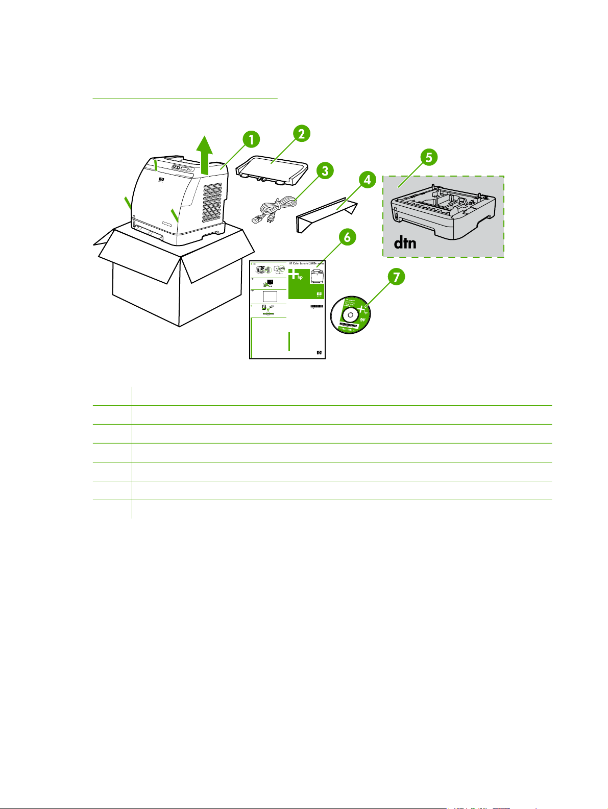
Package contents
Figure 2-2 Package contents on page 20 lists the package contents for the HP Color LaserJet 2605,
2605dn, and 2605dtn.
Figure 2-2 Package contents
1 HP Color LaserJet 2605 Series printer
2 Paper delivery tray
3 Power cable
4 Dust cover
5 Additional 250-sheet paper tray (optional on 2605 and 2605dn)
6 Getting Started Guide
7 Software and user documentation CD-ROM
20 Chapter 2 Installation ENWW
Page 31

Install input devices
Installing Tray 3 (2605dtn)
1. Turn off the power switch on the printer.
2. Unplug the power cable.
3. Place the printer on optional Tray 3, aligning the three (3) pegs on Tray 3 with the holes on the
printer.
Loading Tray 1
Tray 1 (the single sheet priority feed slot) prints single sheets of print media or a single envelope.
Use Tray 1 when feeding one sheet of paper, envelope, postcard, label, HP LaserJet glossy paper,
ENWW Install input devices 21
Page 32

HP LaserJet Photo paper, or transparency. You can also use Tray 1 to print the first page on
different media than the rest of the document.
1. Media guides ensure that the media is correctly fed into the printer and that the print is not
skewed (crooked on the media). Slide the media-width guides slightly wider than the print media.
22 Chapter 2 Installation ENWW
Page 33

2. Feed print media into Tray 1 with the side to be printed down, and the top, short edge in first.
Make sure that the media is inserted far enough into the printer for the paper feed mechanism
to grab the media.
NOTE There is a short pause before the paper is picked up.
NOTE To load special media such as labels, transparencies, HP LaserJet glossy paper,
HP LaserJet Photo paper, and letterhead or printed forms, feed or place the media with
the side to be printed facing down.
NOTE If you are printing on both sides, see the HP Color LaserJet 2605, 2605dn,
2605dtn User Guide for loading instructions.
Loading Trays 2 and 3
Tray 2 and optional Tray 3 are accessed from the front of the printer and hold up to 250 sheets of
paper. Tray 2 also supports other media such as envelopes, postcards, transparencies, HP LaserJet
glossy paper, and HP LaserJet Photo paper.
NOTE Tray 3 is standard on HP Color LaserJet 2605dtn.
ENWW Install input devices 23
Page 34

NOTE Instructions are the same for loading media in Tray 2 and optional Tray 3.
1. Pull Tray 2 or optional Tray 3 out of the printer and remove any paper.
2. Move the rear guides to match the size of paper that you are loading. Tray 2 and optional Tray 3
accept several standard paper sizes.
3. If printing paper longer than letter/A4, extend the rear of the tray until it matches the size you
are loading.
24 Chapter 2 Installation ENWW
Page 35

4. Slide the media-width guides slightly wider than the print media.
NOTE Load 10 envelopes or less into Tray 2 with the flaps on the right side, the side to
be printed facing up, and with the short edge leading into the printer. If the envelope has
a flap on a short edge, this edge must enter the printer first.
ENWW Install input devices 25
Page 36

5. Load the media.
NOTE If this is special paper such as labels, transparencies, HP LaserJet glossy paper,
HP LaserJet Photo paper, and letterhead or printed forms, load it with the side to be
printed on facing up and the top edge toward the front of the tray. For additional
information about printing on special print media, see the HP Color LaserJet 2605,
2605dn, 2605dtn User Guide
26 Chapter 2 Installation ENWW
Page 37

6. Make sure that the stack of paper is flat in the tray at all four corners, and keep it below the
height tabs on the media-length guide in the rear of the tray.
7. Slide the tray into the printer. The back of the tray will protrude from the back of the printer.
NOTE If you are printing on both sides, see the HP Color LaserJet 2605, 2605dn, 2605dtn
User Guide for loading instructions.
ENWW Install input devices 27
Page 38

28 Chapter 2 Installation ENWW
Page 39

3 Managing and maintenance
This chapter contains information about these maintenance topics:
Control panel menus
●
●
Managing supplies
Cleaning the printer
●
Cartridge out override
●
Calibrating the printer
●
Managing the printer
●
ENWW 29
Page 40

Control panel menus
Using the control panel menus
To gain access to the control panel menus, use the following steps.
1.
Press Select
2.
Press the Right arrow
3.
Press Select
4.
Press Cancel Job
.
or Left arrow
button to navigate the listings.
to select the appropriate option.
to cancel an action or return to the Ready state.
Control panel menu map
From the control panel Main menu, the following menus are available:
NOTE Default settings are indicated on the control panel by an asterisk (*).
Menu Sub-menus and options Description
Photo functions (HP Color LaserJet
2605dtn only)
● Print photos
Job settings
●
Select photos
●
● Index print
● Fast
Use these options to configure settings
for printing photos.
Best
●
Reports ● Demo Page
Menu structure
●
Config report
●
● Supplies Status
● Network report
Usage page
●
● PCL font list
● PS font list
PCLXL font list
●
Photo Setup (HP Color LaserJet
2605dtn only)
● Def. image size
Def. # of copies
●
Def. output color
●
Use these options to print various
printer reports.
Use these options to set up defaults for
photo printing.
30 Chapter 3 Managing and maintenance ENWW
Page 41

Menu Sub-menus and options Description
SYSTEM SETUP
Language (select desired
●
language)
● Paper setup
● Def. paper size (Letter,
Legal, A4)
● Def. paper type (select
desired paper type)
Tray 2 (select paper type
●
and size)
● Paper out action (Wait
forever, Cancel, Override
size)
● PRINT QUALITY
CALIBRATE COLOR
●
Cartridge low
●
● REPLACE SUPPLIES
Display contrast (select desired
●
contrast settings)
● Courier font
Use these menus to select system
settings.
Regular
●
Dark
●
Service ● Restore defaults
Cleaning Mode
●
Less paper curl
●
● Off
● On
Archive print
●
● Off
● On
Network config. (HP Color LaserJet
2605dn and 2605dtn)
TCPIP config
●
● Link Speed
● Memory card
Use these menus to calibrate, restore
factory default settings, and clean the
print paper path.
Use these options to configure network
settings.
ENWW Control panel menus 31
Page 42

Managing supplies
For warranty information about these supplies, see Print Cartridge Limited Warranty Statement
on page 235.
Supplies life
The life of a print cartridge depends on the amount of toner that print jobs require. When printing text
at approximately 5% coverage, a cyan, magenta, or yellow print cartridge for the HP Color LaserJet
2605 Series printers lasts an average of 2,000 pages, and a black print cartridge lasts an average of
2,500 pages. A typical business letter has 5% coverage.
Checking and ordering supplies
You can check the supplies status by using the printer control panel, printing a Supplies Status page,
or viewing the HP ToolboxFX. Hewlett-Packard recommends that you place an order for a
replacement print cartridge when you first receive the Low message for a print cartridge. For typical
use, the Order message indicates that approximately two weeks of life remain. When you use a new,
authentic HP print cartridge, you can obtain the following types of supplies information:
● Amount of toner remaining
Estimated number of pages remaining
●
Number of pages printed
●
● Other supplies information
NOTE If the printer is connected to the network, you can set the HP ToolboxFX to notify you
by e-mail when a print cartridge is low or is near the end of its useful life. If the printer is
directly connected to a computer, you can set HP ToolboxFX to notify you when supplies are
low.
To check status and order using the control panel
Do one of the following:
● Check the supplies status gauges on the printer control panel. These gauges indicate when a
print cartridge is low or empty. The lights also indicate when a non-HP print cartridge is first
installed.
● To print the Supplies Status page from the printer, on the printer control panel, select Reports
Menu, and then Supplies Status. See
If the supplies levels are low, you can order supplies through your local HP dealer, by telephone, or
online. See the HP Color LaserJet 2605, 2605dn, 2605dtn User Guide for part numbers. See
http://www.hp.com/go/ljsupplies to order online.
Supplies Status page on page 41 for more information.
To check and order supplies using HP ToolboxFX
You can configure HP ToolboxFX to notify you when the supplies are low. You can choose to receive
alerts by e-mail or as a pop-up message or taskbar icon. To order supplies by using the
HP ToolboxFX, in the Other Links area, click Order supplies. You must have Internet access to
connect to the Web site.
For more information, see
32 Chapter 3 Managing and maintenance ENWW
HP ToolboxFX on page 44.
Page 43

To check and order using HP Web Jetadmin
In HP Web Jetadmin, select the printer. The device status page shows supplies information. To
order, use the HP ToolboxFX.
Storing supplies
Follow these guidelines for storing print cartridges:
Do not remove the print cartridge from its package until you are ready to use it.
●
CAUTION To prevent damage, do not expose the print cartridge to light for more than a
few minutes.
● See Table A-4 Environmental specifications on page 231 for operating and storage temperature
ranges.
● Store the supply in a horizontal position.
● Store the supply in a dark, dry location away from heat and magnetic sources.
Replacing and recycling supplies
To install a new HP print cartridge, follow the instructions that are included on the box that contains
the new supply, or see the Getting Started Guide.
To recycle supplies, place the used supply in the box in which the new supply arrived. Use the
enclosed return label to send the used supply to HP for recycling. For complete information, see the
recycling guide that is included with each new HP supply item. See
on page 244 for more information about HP's recycling program.
HP LaserJet printing supplies
HP policy on non-HP supplies
Hewlett-Packard Company cannot recommend the use of non-HP supplies, either new or
remanufactured. Because they are not HP products, HP cannot influence their design or control their
quality. Service or repairs required as a result of using a non-HP supply will not be covered under the
printer warranty.
When you insert a supply into the printer, the printer will inform you if the supply is not a genuine HP
supply. If you insert a genuine HP supply that has reached the low state from another HP printer, the
printer identifies the supply as non-HP. Simply return the supply to the original printer to reactivate
HP features and functionality.
Resetting the printer for non-HP supplies
When you install a non-HP print cartridge, the light next to the print cartridge you replaced blinks and
the Attention light is on. In order to print with this supply, you must press
install this non-HP supply. The status gauges will not indicate when this type of supply is low or empty.
CAUTION The printer will not stop printing when this type of supply is empty. Printer
damage could occur if the printer prints with an empty print cartridge. See Hewlett-Packard
limited warranty statement on page 234 and Print Cartridge Limited Warranty Statement
on page 235.
(Select) the first time you
ENWW Managing supplies 33
Page 44

HP anti-counterfeit website
Visit the HP anti-counterfeit website at http://www.hp.com/go/anticounterfeit if the supplies status
gauges or HP ToolboxFX indicates that the print cartridge is not an HP print cartridge and you think
that it is genuine.
34 Chapter 3 Managing and maintenance ENWW
Page 45

Cleaning the printer
During the printing process, paper, toner and dust particles can accumulate inside the printer. Over
time, this buildup can cause print-quality problems such as toner specks or smearing. This printer
has a cleaning mode that can correct and prevent these types of problems.
To remove toner build-up
During the printing process, toner can accumulate inside the printer. Over time, this buildup can
cause print-quality problems. Each time you replace the black print cartridge, remove toner build-up.
1. Open the front door.
ENWW Cleaning the printer 35
Page 46

2. Locate the blue cleaning tool that is situated to the left above the black print cartridge.
3. Move the cleaning tool back and forth across the cartridge five times.
4. Ensure that the cleaning tool is returned to the left when the cleaning is finished.
5. Close the front door.
6. Run a cleaning page.
NOTE You will get toner on your hands when you perform this cleaning. To remove toner,
wash your hands with cool water.
36 Chapter 3 Managing and maintenance ENWW
Page 47

To clean the paper path using HP ToolboxFX
NOTE Use the following procedure to clean the paper path using the HP ToolboxFX. To
clean the engine when the computer is running an operating system that does not support
HP ToolboxFX, see the late-breaking Readme on the root of the CD-ROM, or visit
http://www.hp.com/support/clj2605.
1. Make sure that the printer is turned on and in the Ready state.
2. Open the HP ToolboxFX.
3. On the Troubleshooting tab, click Maintenance, click Cleaning Page, and then click Print. A
page with a pattern prints from the printer.
4. At the printer, remove any print media in Tray 2 or optional Tray 3.
5. Remove the page that printed and load it face-down into Tray 2 or optional Tray 3.
6. At the computer, press Clean.
ENWW Cleaning the printer 37
Page 48

Cartridge out override
What is it?
The HP Color LaserJet 2605 Series printers display an ORDER SUPPLIES message when a
cartridge is running low and a REPLACE SUPPLIES message when a cartridge has been depleted.
To ensure optimal print quality, HP recommends replacing a cartridge when the REPLACE
SUPPLIES message is displayed. Replacing the cartridge at this point can help prevent waste of
media or other cartridges when one cartridge produces poor print quality.
The Cartridge Out Override feature allows the printer to continue using a cartridge that has reached
the recommended replacement point.
WARNING! Using Override may result in unsatisfactory print quality and unavailability of
certain features (such as toner remaining information).
WARNING! All print defects or supply failures incurred when an HP supply is used in
Override will not be considered defects in materials or workmanship in the supply under HP's
Print Cartridge Limited Warranty Statement. For Warranty information, see Print Cartridge
Limited Warranty Statement on page 235.
Configuration
Cartridge Out Override can only be enabled from the printer's control panel menu.
1.
From the main menu, press
2.
Press
3.
Press
4.
Press
5.
Press
If STOP AT OUT is selected, the printer will stop printing when a cartridge reaches the
recommended replacement point. If OVERRIDE OUT is selected, the printer will continue printing
when a cartridge reaches the recommended replacement point. The factory default setting is STOP
AT OUT.
(Right arrow) to PRINT QUALITY and press
(Right arrow) to REPLACE SUPPLIES and press
(Right arrow) to OVERRIDE OUT and press
(Select).
(Right arrow) to SYSTEM SETUP and press (Select).
(Select).
(Select).
(Select).
On-going operation
Override can be enabled or disabled at any time, and does not have to be re-enabled for each
cartridge. The printer will automatically continue printing when a cartridge reaches recommended
replacement. The printer will display a message Replace supplies Override in Use while a
cartridge is used in Override mode. When the cartridge is replaced with a new supply, Override will
de-activate until another cartridge reaches recommended replacement.
38 Chapter 3 Managing and maintenance ENWW
Page 49

Calibrating the printer
The printer automatically calibrates at various times. You can adjust the calibration settings by using
the HP ToolboxFX.
Environmental differences or aging print cartridges might cause fluctuations in image density. The
printer accounts for this with image stabilization control. The printer automatically calibrates at
various times to maintain the highest level of print quality. You can also request a calibration by using
the HP ToolboxFX.
The printer does not interrupt a print job to calibrate. It waits until the job is complete before
calibrating or cleaning. While the printer is calibrating, it pauses printing for the time that is required
to complete the calibration.
To calibrate the printer at the printer
1.
To calibrate from the printer, press
SYSTEM SETUP.
2.
3.
4.
5.
6.
7.
8.
9.
Press
Press
Press
Press
Press
Press
Press
Press
(Select).
(Left arrow) or (Right arrow) until the display reads PRINT QUALITY.
(Select).
(Left arrow) or (Right arrow) until the display reads CALIBRATE COLOR.
(Select).
(Left arrow) or (Right arrow) until the display reads CALIBRATE NOW.
(Select).
(Select) to confirm CALIBRATE NOW.
(Left arrow) or
(Right arrow) until the display reads
To calibrate the printer from the HP ToolboxFX
1. Open the HP ToolboxFX in one of these ways:
On the desktop, double-click the HP ToolboxFX icon.
●
● On the Start menu, point to Programs, point to HP, point to HP Color LaserJet 2605
Series, and click HP ToolboxFX.
2. Click the Troubleshooting tab and then click Troubleshooting Tools (on the left side of the
screen).
3. In the Calibration section, click CALIBRATE NOW.
ENWW Calibrating the printer 39
Page 50

Managing the printer
This printer comes with several software tools that help you monitor, troubleshoot problems with, and
maintain the printer. Information about using these tools is in the following sections:
Device pages and reports
●
●
Menu map
HP ToolboxFX
●
Using the embedded Web server
●
Device pages and reports
Special pages reside within the memory of the printer. These pages help you to diagnose and solve
problems with the printer.
If the printer language was not correctly set during installation, you can set the language manually so
that the pages print in one of the supported languages. Change the language by using the
HP ToolboxFX.
Demo page
To print the Demo page, press the (Left arrow) or (Right arrow) buttons on the printer control
panel simultaneously. You can also print this page from the HP ToolboxFX.
Configuration page
The Configuration page lists current settings and properties of the printer. You can print a
Configuration page from the printer or the HP ToolboxFX.
To print the Configuration page from the control panel
1.
2.
3.
4.
Press
Press
Press
Press
(Left arrow) or (Right arrow) to select the Reports menu.
(Select).
(Left arrow) or
(Select) to print the Configuration Report page.
(Right arrow) to select Config report.
40 Chapter 3 Managing and maintenance ENWW
Page 51

1. Product Information. This section contains basic information about the printer, such as the
product name and the serial number.
2. Memory. This section lists memory-related information, such as the total memory that is
installed.
3. Paper Settings. This section lists information about the media type for each tray and about the
type settings for all the media that the printer supports.
4. Page Counts. This section lists the total number of pages printed, the number of color pages
printed, and information about paper jams.
5. Product Settings. This section lists information that is gathered during software installation,
including the language and the company name.
6. Network Settings. This section contains network information about the printer such as the Host
Name, Hardware Address, and IP Address.
7. Paper Types. This section contains information about paper types that can be configured by
the user.
8. Status Log. This section contains information about printer errors.
Supplies Status page
The Supplies Status page lists the remaining life of HP print cartridges. It also lists the estimated
pages remaining, number of pages printed, and other supplies information. You can print a Supplies
Status page from the printer or the HP ToolboxFX.
ENWW Managing the printer 41
Page 52

To print the Supplies Status page from the control panel
1.
2.
3.
4.
Press
Press
Press
Press
(Left arrow) or (Right arrow) to select the Reports menu.
(Select).
(Left arrow) or
(Right arrow) to select Supplies Status.
(Select) to print the Supplies Status page.
NOTE Supplies information is also available through the HP ToolboxFX.
1. Print cartridge area. This area contains a section for each of the print cartridges and provides
information about HP print cartridges. This information includes the part number for each print
cartridge, whether each print cartridge is low, and the life remaining for each print cartridge,
which is expressed as a percentage, as a graphic, and as the estimated number of pages
remaining. This information might not be provided for non-HP supplies. In some cases, if a nonHP supply is installed, an alert message displays instead.
2. Ordering Information. This section contains basic information about how to order new HP
supplies.
3. Return & Recycling. This section contains a link to the Web site that you can visit for
information about recycling.
42 Chapter 3 Managing and maintenance ENWW
Page 53

Networking page
The Networking report option prints a Network configuration report. You can print this page using the
printer control panel. Use the following steps to print the Network configuration report.
1.
2.
3.
4.
Press
Press
Press
Press
(Left arrow) or
(Select).
(Left arrow) or (Right arrow) to select Network report.
(Select) to print the Network configuration page.
(Right arrow) to select the Reports menu.
Fonts pages
The fonts pages provide lists of the available fonts on the printer, including PostScript (PS) fonts,
PCL fonts, and PCL6 fonts (PCLXL). You can print these font pages using the printer control panel.
Use the following steps to print a fonts page.
1.
2.
3.
4.
Press
Press
Press
Press
(Left arrow) or (Right arrow) to select the Reports menu.
(Select).
(Left arrow) or
(Select) to print the selected fonts page.
(Right arrow) to select PS font list, PCLXL font list, or PCL font list.
Usage page
The Usage Page provides information on the number and types of pages printed by the printer. You
can print the usage page using the printer control panel. Use the following steps to print a usage page.
1.
2.
3.
4.
Press
Press
Press
Press
(Left arrow) or (Right arrow) to select the Reports menu.
(Select).
(Left arrow) or
(Select) to print the Usage Page.
(Right arrow) to select Usage page.
Menu map
The menu map lists the menu structure for each option available on the printer control panel. Use the
following steps to print a menu map.
To print a menu map
1.
2.
3.
4.
Press
Press
Press
Press
(Left arrow) or
(Select).
(Left arrow) or (Right arrow) to select Menu structure.
(Select) to print the Menu map.
(Right arrow) to select the Reports menu.
ENWW Managing the printer 43
Page 54

HP ToolboxFX
HP ToolboxFX is a Web-based program that you can use to complete the following tasks:
● Check the printer status.
Configure the printer settings.
●
View troubleshooting information.
●
● View online documentation.
You can view HP ToolboxFX when the printer is directly connected to your computer or when it is
connected to the network. You must perform a typical software installation to use HP ToolboxFX.
NOTE HP ToolboxFX is not supported for Windows 98 SE, Windows Me, Windows
Server 2003, or Macintosh operating systems.
NOTE You do not have to have Internet access to open and use HP ToolboxFX.
To view HP ToolboxFX
Open HP ToolboxFX in one of these ways:
● In the Windows system tray or on your desktop, double-click the HP ToolboxFX icon.
● On the Windows Start menu, click Programs (or All Programs in Windows XP), click HP, click
HP Color LaserJet 2605 Series , and then click HP ToolboxFX.
The HP ToolboxFX software contains the following sections:
Status on page 45
●
Alerts on page 46
●
Help on page 46
●
Device settings on page 47
●
Network settings on page 51
●
44 Chapter 3 Managing and maintenance ENWW
Page 55

Status
The HP ToolboxFX Status folder contains links to the following main pages:
● Device Status. View printer status information. This page indicates printer conditions such as a
jam or an empty tray. After you correct a problem with the printer, click Refresh button to
update the printer status.
Supplies Status. View detailed supplies status such as the estimated percent of toner
●
remaining in the print cartridge and the number of pages that have been printed with the current
print cartridge. This page also has links to order supplies and to find recycling information.
Device Configuration. View a detailed description of the current printer configuration, including
●
the amount of memory installed and whether optional trays are installed.
Network Configuration. View a detailed description of the current network configuration,
●
including the IP address and network status.
Print Info Pages. Print the Configuration page and various other information pages that are
●
available for the printer, such as the Supplies Status page and the Demo page.
Event Log. View a history of printer errors. The most recent error is at the top of the list.
●
Event log
The Event log is a four-column table where the printer events are logged for your reference. The log
contains codes that correspond to the error messages that appears on the printer control-panel
display. The number in the Page Count column specifies the total number of pages that the printer
had printed when the error occurred. The Event log also contains a brief description of the error. For
more information about error messages, see
Control-panel messages on page 136.
ENWW Managing the printer 45
Page 56

Alerts
The HP ToolboxFX Alerts folder contains links to the following main pages:
● Set up Status Alerts. Set up the printer to send you pop-up alerts for certain events, such as
low toner levels.
● Set up E-mail Alerts. Set up the printer to send you e-mail alert messages for certain events,
such as low toner levels.
Set up status alerts
Use HP ToolboxFX to set up the printer so that it issues pop-up alerts to your computer when certain
events occur. Events that trigger alerts include jams, low levels of toner in HP print cartridges, nonHP print cartridge in use, empty input trays, and specific error messages.
Select the pop-up format, the system tray icon format, the desktop format, or all three for the alerts.
The pop-up alerts only appear when the printer is printing from the computer on which you set up the
alerts.
NOTE You must click Apply before your changes take effect.
Set up e-mail alerts
Use HP ToolboxFX to configure up to two e-mail addresses to receive alerts when certain events
occur. You can specify different events for each e-mail address. Enter the information for the e-mail
server that will send out the e-mail alert messages for the printer.
NOTE You must click Apply before your changes take effect.
Help
The HP ToolboxFX Help folder contains links to the following main pages:
● Troubleshooting. Print troubleshooting pages, clean the printer, and display Microsoft Office
Basic Colors. For more information on Microsoft Office Basic colors, see the HP Color LaserJet
2605, 2605dn, 2605dtn User Guide.
● How Do I? View the How Do I? Help for help with specific tasks.
● Animated demonstrations
User Guide. View information about the printer usage, warranty, specifications, and support.
●
The user guide is available in both HTML and PDF format.
Readme. View important information about the printer that is not available in the user guide.
●
The late-breaking Readme contain last-minute information about the printer (in English only).
46 Chapter 3 Managing and maintenance ENWW
Page 57

Device settings
The HP ToolboxFX Device Settings folder contains links to the following main pages:
● Device Information. View information about the printer, such as the printer description and a
contact person.
● Paper handling. Change the printer paper-handling settings, such as default paper size and
default paper type.
Printing. Change the default printer print settings, such as number of copies and paper
●
orientation.
PCL5e. View and change the PCL5e settings.
●
PostScript. View and change the PS settings.
●
Print quality. Change the printer print-quality settings.
●
● Print density. Change the print density settings, such as contrast, highlights, midtones, and
shadows.
● Paper types. Change the printer mode settings for a each media type, such as letterhead,
prepunched, or glossy paper.
● Memory Card. Change the printer settings, such as image size, number of copies, and output
color when printing photos using memory cards.
● System Setup. Change the printer system settings, such as printer language and jam recovery.
● Service. Gain access to various procedures required to maintain the printer.
Save/restore settings. Save the current settings for the printer to a file on your computer. Use
●
this file to load the same settings onto another printer or to restore these settings to this printer
at a later time.
Device information
The information that you type in these fields appears on the Configuration page. You can type any
character in each of these fields.
NOTE You must click Apply before your changes take effect.
ENWW Managing the printer 47
Page 58

Paper handling
Use the HP ToolboxFX paper-handling options to configure your default settings. These are the
same options that are available on the SYSTEM SETUP and Paper setup menus on the control
panel. For more information, see
Three options are available for handling print jobs when the product is out of media:
● Select Wait For Paper To Be Loaded.
● Select Cancel from the Paper out action drop-down list to cancel the print job.
● Select Override from the Paper out time drop-down list to send the print job to another paper
tray.
The Paper out time field specifies how long the printer waits before acting on your selections. You
can specify from 0 to 3600 seconds.
Control panel menus on page 30.
NOTE You must click Apply before your changes take effect.
Printing
Use the HP ToolboxFX printing settings options to configure the settings for all print functions. These
are the same options that are available on the Print Settings menu on the control panel. For more
information, see
Control panel menus on page 30.
NOTE You must click Apply before your changes take effect.
PCL5e
Use the PCL5e options to configure the settings when you are using the PCL5e print personality.
These are the same options that are available on the PCL5e menu on the control panel.
NOTE You must click Apply before your changes take effect.
48 Chapter 3 Managing and maintenance ENWW
Page 59

PostScript
Use the PostScript option when you are using the PostScript print personality. When the Print
PostScript error option is turned on, the PostScript error page automatically prints when PostScript
errors occur.
NOTE You must click Apply before your changes take effect.
Print quality
Use the HP ToolboxFX print-quality options to improve the appearance of your print jobs. These are
the same options that are available on the SYSTEM SETUP and PRINT QUALITY menu on the
control panel. For more information, see
For Color Calibration, the following options are available:
●
Power On Calibration
●
● Calibration Timing
● Calibrate Now
For Grayscale Printing, the following options are available:
●
Resolution. Select 600 resolution for average print jobs and Fast Res 1200 for higher-
●
quality print jobs. Select ProRes 1200 for the highest-quality print job, but a longer printing
time.
Control panel menus on page 30.
● REt. You can turn on REt, which HP provides for improved print quality.
● Economode. Turn Economode on when you are printing average print jobs. Economode
reduces print quality, but increases the life of your print cartridge. To increase print quality,
turn Economode off. HP does not recommend full-time use of Economode.
NOTE You must click Apply before your changes take effect.
Print density
The print density settings allow you to make fine adjustments of the density (amount) of cyan,
magenta, yellow, and black toner in your images, pages, and documents.
● Contrasts. Contrast is the density difference between light (highlight) and dark (shadow) colors.
To increase the difference between light and dark colors (equivalent to a negative highlight
adjustment and a positive shadow adjustment), use a positive contrast setting. To decrease the
difference between light and dark colors (equivalent to a positive highlight adjustment and a
negative shadow adjustment), use a negative contrast setting.
● Highlights. Highlight colors are colors near white. To make highlight colors darker, use a
positive highlight setting, and to make highlight colors lighter use a negative highlight setting.
This adjustment does not affect midtone or shadow colors.
ENWW Managing the printer 49
Page 60

Midtones. Midtone colors are about halfway between white and solid density. To make midtone
●
colors darker, use a positive midtone setting, and to make midtone colors lighter use a negative
highlight setting. This adjustment does not affect highlight or shadow colors.
● Shadows Shadow colors are colors near solid density. To make shadow colors darker, use a
positive shadow setting, and to make shadow colors lighter use a negative shadow setting. This
adjustment does not affect highlight or midtone colors.
Paper types
Use these HP ToolboxFX Paper types options to configure print modes that correspond to the
various media types. When you select Restore Modes, all of the modes are reset to the factory
settings.
NOTE You must click Apply before your changes take effect.
Memory card (HP Color LaserJet 2605dtn)
Use the HP ToolboxFX memory card options to configure print settings when using memory cards.
Three options are available for configuring the printer when using memory cards.
Photo image size. Select the size photos to print from the drop-down list.
●
Photo number of copies. Type the number of copies from 0 to 99 to print for each image.
●
Photo output color. Select either Color or Monochrome from the drop-down list.
●
Select the Enable memory cards check box to save the settings.
50 Chapter 3 Managing and maintenance ENWW
Page 61

System setup
Use the HP ToolboxFX system settings options to configure miscellaneous print settings. These
settings are not available from the printer control panel.
NOTE You must click Apply before your changes take effect.
Service
During the printing process, paper, toner, and dust particles can accumulate inside the printer. Over
time, this buildup can cause print-quality problems such as toner specks or smearing. HP ToolboxFX
provides an easy method for cleaning the paper path. For more information, see
path using HP ToolboxFX on page 37.
To clean the paper
Network settings
The network administrator can use the HP ToolboxFX Network Settings folder to control the
network-related settings for the printer when it is connected to an IP-based network.
The following options are available:
● IP Configuration
● Advanced
SNMP
●
Network Configuration
●
Password
●
Using the embedded Web server
When the printer is directly connected to a computer, use the HP ToolboxFX to view Web pages for
the printer status.
When the printer is connected to the network, the embedded Web server is automatically available.
You may access the embedded Web server from any supported browser.
The embedded Web server allows you to view printer and network status and to manage printing
functions from your computer instead of using the printer control panel. Below are examples of what
you can do using the embedded Web server:
View printer status information.
●
● Set the type of paper loaded in each tray.
● Determine the remaining life on all supplies and order new ones.
● View and change tray configurations.
View and change the printer.
●
View and print internal information pages.
●
● View and change network configuration.
ENWW Managing the printer 51
Page 62

The embedded Web server supports the following browsers:
● Microsoft Internet Explorer 6.0 and later
● Netscape 7.0 or later
Opera 7.0 or later
●
Firefox 1.0 or later
●
Mozilla 1.6 or later
●
● Safari 1.2 or later
The embedded Web server works when the printer is connected to an IP-based network. The
embedded Web server does not support IPX-based or AppleTalk printer connections. You do not
need Internet access to open and use the embedded Web server.
To access the embedded Web server using a network connection
In a supported Web browser on your computer, type the IP address for the printer in the address/
URL field. (To find the IP address, print a configuration page. For more information about printing a
configuration page, see
NOTE If you are unable to access the embedded Web server using the IP address, you can
use the host name.
Configuration page on page 40.)
NOTE After you open the URL, you can bookmark it so that you can return to it quickly in the
future.
1. The embedded Web server has three tabs that contain settings and information about the
printer: the Information tab, the Settings tab, and the Networking tab. Click the tab that you
want to view.
2. See the following sections for more information about each tab.
Information tab
The Information pages group consists of the following pages.
● Device Status. This page displays the printer status and shows the life remaining of
HP supplies, with 0% indicating that a supply is empty. The page also shows the type and size
of print media set for each tray.
● Configuration. This page displays the network and product information found on the printer
Configuration page, such as page counts, print settings, and paper options.
● Supplies Status. This page displays the life remaining of HP supplies, with 0% indicating that a
supply is empty. This page also provides supplies part numbers. To order new supplies, click
Order Supplies in the Other Links area on the left side of the window. To visit any Web site,
you must have Internet access.
Print Info Pages. This page provides a remote way to print an internal page for a printer.
●
52 Chapter 3 Managing and maintenance ENWW
Page 63

Settings tab
This tab allows you to configure the printer from your computer. The Settings tab can be password
protected. If this printer is networked, always consult with the printer administrator before changing
settings on this tab.
The Settings tab contains the following pages.
● Paper Handling. Configure paper handling settings from this page.
Printing. Configure the IO Timeout from this page.
●
Print Quality. Use this page to configure color calibration and optimize settings.
●
● Print Density. Use this page to configure print density settings including contrast, highlights,
midtones, and shadows.
● Paper Type Settings. Use this page to configure paper types
● Print Modes. Use this page to configure print mode settings.
● System Setup. Use this page to set up system settings, including jam recovery, auto continue,
display contrast, and printer language.
Service. Use this page to start the cleaning mode and restore factory settings.
●
Networking tab
This tab allows the network administrator to control network-related settings for the printer when it is
connected to an IP-based network.
● IP Configuration. Use this page to set the IP configuration.
Advanced. Use this page to enable network features such as SLP Config, DHCP, BootP, and
●
AutoIP.
mDNS. Use this page to set the mDNS. Use these settings to turn on or off Rendezvous or
●
Bonjour discovery.
SNMP. Use this page to set SNMP protocols.
●
Password. Use this page to set or change the Administrator Password.
●
Other links in HP ToolboxFX
This section contains links that connect you to the Internet. You must have Internet access in order
to use any of these links. If you use a dial-up connection and did not connect when you first opened
the embedded Web server, you must connect before you can visit these Web sites. Connecting
might require that you close the embedded Web server and reopen it.
● HP Instant Support™. Connects you to the HP Web site to help you find solutions. This service
analyzes your printer error log and configuration information to provide diagnostic and support
information specific to your printer.
● Product Registration. Click this link to connect to the HP Web site to register the product.
ENWW Managing the printer 53
Page 64

Order Supplies. Click this link to connect to the HP Web site and order genuine HP supplies,
●
such as print cartridges and paper.
● Product Support. Connects to the support site for the HP Color LaserJet 2605 Series printers
where you can search for help regarding general topics.
54 Chapter 3 Managing and maintenance ENWW
Page 65

4 Operational theory
This chapter contains information about the following topics:
Engine control system
●
●
Image formation system
Pickup and feed system
●
Service-only tools (SERVICE ONLY)
●
ENWW 55
Page 66

Engine control system
Basic sequence of operation
The operational sequence of the printer is controlled by the microcomputer on the DC controller
printed circuit assembly (PCA). The purposes of each period, from power-on until the main motor
stops after the completion of printing, are listed below. See
detailed timing chart.
Table 4-1 Basic operational sequence
Period Purpose Remarks
General timing chart on page 80 for a
WAIT (wait period) From power-on until the end
of the main motor initial drive.
STBY (standby period) From the end of WAIT or
LSTR until the input of print
command from the
formatter. Or, from the end
of LSTR until power-off.
INTR (initial rotation period) From the input of print
command from the formatter
until the pick-up solenoid is
turned on.
PRINT (print period) From the end of INTR until
the developing high-voltage
is off.
LSTR (last rotation period From the developing high-
voltage off until the main
motor stops rotating.
To clear the drum surface
potential and to clean the
ETB.
To keep the printer ready to
print.
To stablize the
photosensitive drum
sensitivity for print
preparation.
To form the image on the
photosensitive drum based
on the VIDEO signals input
from the formatter, and to
transfer the toner image
onto paper.
To deliver the last page
completely. Also used to
clean the ETB.
Detects whether or not the
print cartridge is installed.
The printer enters INTR after
the end of LSTR, when the
print command is input from
the formatter.
The engine control system coordinates all printer functions. It drives the laser/scanner system, the
image formation system, and the pickup and feed system. The engine control system contains the
following components:
● DC controller PCA
● Low-voltage power supply unit
High-voltage power supply PCA
●
56 Chapter 4 Operational theory ENWW
Page 67

Figure 4-1 Engine control system
Power-on sequence
The power-on sequence is for the purpose of the printer initialization and checking for possible
malfunctions.
The following is the sequence from when the printer is turned on until it enters STBY mode.
1. Power on
2. Central processing unit (CPU) initialization
3. ASIC initialization
4. Video interface communication start
5. Residual paper check by each sensor signaling paper presence
6. Initial drive for main motor, pickup motor, and fuser/delivery motor
7. Fuser heater initial drive by controlling fuser temperature targeting for 100°?C
8. Initial drive for scanner motor
9. Failure/Abnormality check
● Detect scanner failure
● Fuser failure
Door open during the above periods
●
10. Communication with memory tag
11. Cartridge presence detection
Motors and fans
The DC controller PCA controls four motors.
ENWW Engine control system 57
Page 68

The specifications of each motor are listed in the following table.
Table 4-2 Motor specifications
Name Purpose Type Direction of
rotation
Motor Main motor (M1) Drive ETB belt,
photosensitive
drum and
developing cylinder
Fuser/delivery
motor (M2)
Pickup motor (M3) Drive pickup roller
Fan (FM1) Circulate air
Drive fuser
pressure roller,
delivery roller and
automatic release
of fuser pressure
and registration
roller
around cartridge
DC motor CW Yes
Stepping motor CW/CCW No
Stepping motor CW No
DC motor — Yes
Failure detection
Main motor failure detection
The CPU determines the main motor failure, stops the printer, and notifies the formatter of error
status, when it encounters the following conditions.
● Main motor start-up abnormality
The interval of the MAIN MOTOR SPEED DETECTION signal (/MAINMFG) does not become
the specified interval after 1000 ms of the main motor drive start.
● Main motor rotation abnormality
The interval of the /MAINMFG signal stays at an irregular interval for 100 ms and longer after
once it has become the specified interval.
Fan motor failure detection
The CPU determines the fan motor failure and notifies the formatter when it encounters the following
condition.
The FAN LOCK signal (FANLCK) is “H” for approximately 10 seconds and longer during fan motor
rotation.
58 Chapter 4 Operational theory ENWW
Page 69

Image formation system
The image formation system serves as the nerve center of the printer and forms a toner image on
paper. It is controlled by the DC controller. The DC controller controls the laser/scanner unit and the
high-voltage power supply PCA to form an image on paper according to the VIDEO signals (VDO, /
VDO) upon reception of a print command from the formatter. There is a memory tag inside each
cartridge. The memory tags read and write data according to the command from the DC controller.
The following figure illustrates the image formation system.
ENWW Image formation system 59
Page 70

Figure 4-2 Image formation system
60 Chapter 4 Operational theory ENWW
Page 71

Image formation process
Figure 4-3 Image formation process
ENWW Image formation system 61
Page 72

The principal process of image formation is described here. The print process can be broadly divided
into five stages with seven steps. A toner image is formed on paper as it goes through each process.
The following figure illustrates the stages and steps of the print process as follows.
1. Electrostatic latent image formation stage
Forms an electrostatic latent image on the photosensitive drum.
Step 1: Primary charging
Step 2: Laser beam exposure
2. Developing stage
Makes the electrostatic latent image on the photosensitive drum surface visible by applying toner.
Step 3: Development
3. Transfer stage
Transfers a toner image on the photosensitive drum onto paper.
Step 4: Transfer
Step 5: Separation
4. Fuser stage
Fuses the toner image on paper.
Step 6: Fuser
5. ETB cleaning stage
Cleans the residual toner on the photosensitive drum.
Step 7: ETB cleaning
Latent image formation
This stage consists of two steps and forms an electrostatic latent image on the photosensitive drum.
When the last step in this stage is completed, a negative electrical charge remains in the unexposed
drum surface area by the laser beam and is removed from the exposed area. The image with
negative charge on the drum is called an “electrostatic latent image”, and it is invisible to the human
eye.
62 Chapter 4 Operational theory ENWW
Page 73

Figure 4-4 Latent image formation
Laser/scanner system
The laser/scanner system forms latent images on the photosensitive drum according to the VIDEO
signals sent from the formatter. It consists of the laser driver PCA, the scanner motor, and so forth.
The figure below illustrates the laser/scanner unit.
Figure 4-5 Laser beam exposure
Developing stage
The electrostatic latent image on the photosensitive drum surface is visualized by applying the toner
in this process. This printer utilizes the projection development method by the non-magnetic, singlecomponent toner.
ENWW Image formation system 63
Page 74

Figure 4-6 Developing stage
The toner has an insulating property and has negative charge potential from friction with the rotating
developing cylinder and the developing blade surface.
The area of the photosensitive drum, where the laser beam is exposed, has higher potential than the
toner, which is charged negatively on the cylinder. When this area contacts the toner layer
(negatively charged), the toner jumps onto the drum surface by the potential difference between the
drum surface and the cylinder (higher potential on drum side). This is called the projection
development and it visualizes the electrostatic latent image on the drum. The developing cylinder is
applied the AC bias in order to make the toner jump easier onto the drum surface and improve the
contrast of the output image.
This printer is able to adjust the image density by changing the potential difference between the
cylinder and the photosensitive drum surface according to changes of the developing DC bias based
on the IMAGE DENSITY INFORMATION signal sent from the formatter.
The developing sheet improves the print quality and also prevents toner from scattering.
Print cartridge
The cartridge forms a visible toner image on the photosensitive drum. There are four print cartridges:
magenta (M), cyan (C), yellow (Y), and black (K).
64 Chapter 4 Operational theory ENWW
Page 75

Figure 4-7 Print cartridge structure
Transfer belt (ETB)
The ETB unit feeds paper as well as transfers toner onto the paper.
The ETB unit consists of the ETB, ETB feed roller, ETB driven roller, and color misregistration/
density sensor unit.
As the main motor rotates the ETB feed roller, the ETB feed roller rotates the ETB belt. The transfer
roller and the ETB driven roller are engaged with the ETB.
During printing, the picked up paper is conveyed in between the ETB and the photosensitive drum,
and simultaneously the toner image is transferred onto the paper. The ETB is also used for color
misregistration corrective control and the image stabilization control. The pattern image for the color
misregistration or image density determination is transferred onto the belt. This pattern image is read
in the color misregistration/density sensor unit.
The following is the diagrammatic sketch of the ETB unit.
ENWW Image formation system 65
Page 76

Figure 4-8 ETB unit
Transfer stage
The transfer stage is to transfer the toner image on the photosensitive drum surface onto paper.
Figure 4-9 Transfer stage
66 Chapter 4 Operational theory ENWW
Page 77

The toner on the photosensitive drum surface is transferred onto the paper according to the positive
charge from the back side of the paper. Each color’s toner image is transferred in order of M, C, Y,
and K, and forms one toner image overlaying one color’s image on another.
Separation stage
Figure 4-10 Separation stage
The paper is separated from the drum by its elasticity (Curvature Separation). The static charge on
the back side of the paper is decreased with the electrostatic eliminator in order to stablize the
feeding operation and prevent the crescent spots of printing image under the low temperature and
low humidity environment.
Fusing stage
The toner image transferred onto the paper through the transfer stage can be smeared easily
because it is only attracted to the paper by the static electricity. In the fusing stage, the printer used
heat and pressure to make the image permanent.
Figure 4-11 Fusing stage
The toner image is fused onto the paper by using the on-demand fuser method in this step. This
printer utilizes the ceramic heater with lower heat capacity, which warms up quickly, does not require
the power supply during STBY mode, and saves energy. The printer applies the DC positive bias to
ENWW Image formation system 67
Page 78

the fuser pressure roller so that the transferred toner stays on the paper and toner scattering (offset)
is prevented.
68 Chapter 4 Operational theory ENWW
Page 79

Pickup and feed system
The pickup and feed system, which picks up and feeds paper, consists of the various feed rollers.
This printer has two pickup sources: the cassette and the single-sheet priority feed slot, and one
delivery source: the face-down tray. The following components are part of the pickup and feed system:
Manual feed slot paper sensor (SR3): detects the presence of paper in the single-sheet priority
●
feed slot
Cassette paper sensor (SR2): detects the presence of paper in the cassette
●
DC controller controls the following to drive each feed roller:
●
● Main motor (M1)
● Fuser/delivery motor (M2)
● Pickup motor (M3)
Solenoid (SL1)
●
Solenoid (SL2)
●
● Solenoid (SL3)
● Photo sensors:
● SR1, SR4, and SR5 on the paper transport path detect the arrival and passage of paper
● SR9 detects the fuser pressure roller alienation in the fuser
SR8 detects the paper width
●
The figure below illustrates the motors, solenoids, and sensors.
NOTE There is a short pause before the paper is picked up.
ENWW Pickup and feed system 69
Page 80

Figure 4-12 Paper pickup and feed system
SR1 Registration paper sensor
SR2 Cassette paper sensor
SR3 Manual feed slot paper sensor
70 Chapter 4 Operational theory ENWW
Page 81

SR4 Fuser delivery paper sensor
SR5 Pre-fuser paper sensor
SR8 Paper width sensor
SR9 Pressure alienation sensor
M1 Main motor
M2 Fuser/Delivery motor
M3 Pickup motor
SL1 Cassette pickup solenoid
SL2 Magenta, cyan, and yellow developing cylinder drive solenoid
SL3 Black developing cylinder drive solenoid
Manual feed slot pickup mechanism
This mechanism picks up one sheet of paper only that is inserted into the single-sheet priority feed
slot and then into the printer. This printer does not have a pickup roller in the single-sheet priority
feed slot. Instead of a pickup roller, the registration roller picks up paper. The presence of paper in
the single-sheet priority feed slot is detected by the single-sheet priority feed slot paper sensor
(SR3). The following is the operational sequence of the single-sheet priority feed slot pickup.
1. If paper is set into the single-sheet priority feed slot during STBY mode, the single-sheet priority
feed slot paper sensor (SR3) detects it.
2. When the paper is detected, the DC controller drives the pickup motor (M3) for 5 seconds. The
paper is fed approximately 5 mm (0.2 inch) and is then caught by the registration roller.
3. After the above operational sequence, the paper is fed by the drive of the registration roller.
Paper feed mechanism
This mechanism feeds one sheet of picked up paper to the fuser. There is a paper width sensor in
the paper transport path to prevent temperature rise at the end of the fuser. It detects paper with
widths of shorter than 190 mm (7.5 inches). The following is the operational sequence of paper feed.
1. Paper skew is corrected by the registration shutter when the paper is fed into the printer.
2. Toner is transfered to the paper from the photosensitive drum and then the paper is fed to the
fuser/delivery stage.
Skew correction by the registration shutter
If the paper fed into the printer is skewed, it will be adjusted when it hits the registration shutter.
Figure 4-13 Skew correction on page 72 illustrates how the registration shutter corrects skewed
paper.
ENWW Pickup and feed system 71
Page 82

Figure 4-13 Skew correction
Jam detection
This printer is provided with the following paper detection sensors to detect the presence of paper
and whether or not the paper feed is operating normally.
Registration paper sensor (SR1)
●
● Pre-fuser paper sensor (SR5)
● Fuser delivery paper sensor (SR4)
The CPU determines a paper jam by checking whether or not paper is present at the sensor at the
check timing. The check timing is stored in the memory of the CPU. If the CPU determines a jam, it
stops the print operation and notifies the formatter of a jam occurrence.
For more information, see
72 Chapter 4 Operational theory ENWW
Clearing jams on page 142.
Page 83

Solenoid, motor, and fan locations
The following illustration shows the locations of the solenoids, motor, and fan.
Figure 4-14 Location of solenoids, motors, and fans
1 Pickup solenoid (SL1)
2 Magenta, cyan, and yellow developing cylinder drive solenoid (SL2)
3 Black developing cylinder drive solenoid (SL3)
4 Main motor (M1)
5 Fusing/delivery motor (M2)
6 Pickup motor (M3)
7 Fan 1 (FM1)
8 Fan 2 (FM2)
9 Duplexing feed motor (M6)
10 Reverse motor (M7)
Printed circuit assembly locations
The following illustration shows the locations of the printed circuit assemblies. Location of the printed
circuit assemblies and list of parts are also identified in
on page 208.
Figure 7-15 PCA assembly location
ENWW Pickup and feed system 73
Page 84

Figure 4-15 Location of printed circuit assemblies
1 DC controller PCA
2 Low-voltage power supply PCA
3 High-voltage power supply PCA
4 Memory controller PCA
5 Duplexing driver PCA
6 Sub high-voltage power supply PCA
250-sheet tray solenoid and printed circuit locations
The following illustration shows the locations of the 250-sheet tray solenoid and printed circuit
assembly.
74 Chapter 4 Operational theory ENWW
Page 85

Figure 4-16 Location of 250-sheet tray solenoid and printed circuit assembly
1 Paper feeder PCA
2 Paper feeder pickup solenoid
3 Paper-pickup feeder unit
Duplexing mechanism
The duplexing mechanism feeds paper to the reversing unit after the first side is printed, and then it
returns the paper to the duplexing feed unit so that the print side of the paper is reversed for secondside printing.
The duplexing driver controls the duplexing feed motor (M6) and the reverse motor (M7), which
drives each feed roller of the duplexing feed unit. It also controls the reverse solenoid (SL5), which
drives the duplexing deflector.
The top cover can be opened to remove jams in the reverse unit. The top cover open sensor (SR7) is
used for open/close detection. After clearing a jam in the duplexing mechanism, open the front door
to make sure there are no jams in other areas.
The paper path is shown in
reverse motor, solenoid, and sensor are shown in
Figure 4-19 Duplexing components on page 79.
and
Figure 4-17 Duplexing paper path on page 76. The duplexing feed motor,
Figure 4-18 Duplexing PCA schematic on page 77
ENWW Pickup and feed system 75
Page 86

Figure 4-17 Duplexing paper path
76 Chapter 4 Operational theory ENWW
Page 87

Figure 4-18 Duplexing PCA schematic
Table 4-3 Duplexing PCA schematic labels
SR1 Registration paper sensor
ENWW Pickup and feed system 77
Page 88

Table 4-3 Duplexing PCA schematic labels (continued)
SR2 Cassette paper sensor
SR3 Manual feed slot paper sensor
SR4 Fixing delivery paper sensor
SR5 Pre-fixing paper sensor
SR7 Top cover open sensor
SR8 Paper width sensor
SR9 Pressure alienation sensor
M1 Main motor
M2 Fixing/delivery motor
M3 Pick-up motor
M6 Duplexing feed motor
M7 Reverse motor
SL1 Cassette pick-up solenoid
SL2 MCY developing cylinder drive solenoid
SL3 Bk developing cylinder drive solenoid
SL5 Reverse solenoid
The operational sequence of duplex printing is as follows:
1. The duplexing driver activates the reverse solenoid (SL5) to drive the duplexing deflector when
the leading edge of paper arrives at the fixing unit. It then rotates the reverse motor (M7)
clockwise and feeds the paper to the reverse unit.
2. The duplexing driver stops the reverse motor and turns off the reverse solenoid after the trailing
edge of the paper passes through the fixing delivery paper sensor.
3. The duplexing driver rotates the reverse motor counter-clockwise to feed the paper to the
duplexing feed unit. It turns on the duplexing feed motor (M6) after a specified time to feed the
paper to the duplexing pick-up position. The oblique roller corrects skew and makes sure that
edge of the paper is flush with the left guide.
4. If the duplexing driver has received the duplexing pick-up command, the paper is fed to the
registration roller. If it has not, the paper is stopped and is fed to the registration roller when the
command is received.
5. The second side of the paper is printed and fed to the delivery tray.
78 Chapter 4 Operational theory ENWW
Page 89

Figure 4-19 Duplexing components
If paper fed from the duplexing pick-up position does not arrive at the registration sensor within a
prescribed period of time, the DC controller stops the printing operation and notifies the video
controller of a duplexing pick-up jam.
ENWW Pickup and feed system 79
Page 90

Service-only tools (SERVICE ONLY)
General timing chart
80 Chapter 4 Operational theory ENWW
Page 91

Printer calibration
Calibration settings are configured with Printer Management Language (PML)/Printer Job Language
(PJL) commands, except for new cartridge installation. Calibration can also be configured using the
embedded Web server and HP ToolboxFX. Calibration occurs during the following conditions and
intervals:
● Power-on calibration
Calibration during power-on can be configured for the following intervals:
Always calibrate at power-on
●
● Never calibrate at power-on
● Calibrate after 1-6 minutes (default is 15 minutes) of idle time after the first job since the
printer was turned on or 12, 24, 48, 96, or 168 hours (default is 48 hours) of idle time.
Page count calibration
●
Calibration occurs at the end of the first job that passes 150 color pages since the previous
calibration occurred. Page count calibration settings can be configured for the following intervals:
Do not do page count calibrations
●
● Calibrate after 150 pages have been printed since the last calibration. This is the default
setting.
NOTE Page count calibration cannot be set using the embedded Web server.
● Elapsed time calibration
Elapsed time calibration will occur when the first job is sent after the elapsed time is exceeded.
Use PML/PJL commands to configure the following intervals:
Do not perform elapsed time calibration
●
After 12, 24, 48, 96, or 168 hours (default is 48 hours) or more have elapsed since the last
●
calibration (or power-on), and after 1-6 minutes (default is 15 minutes) of idle time from the
first job after 12, 24, 48, 96, or 168 hours (default is 48 hours) have elapsed.
On-demand calibration
●
Calibrate the printer using the printer control panel. For more information about printer
calibration, see
New consumable calibration
●
When a new print cartridge is installed, the printer calibrates.
NOTE When a new black print cartridge is replaced, a cleaning page will print before
the printer calibrates.
If printing stops when the cartridge is out, requiring the user to either install a new cartridge or
select to print with toner out override, a calibration will not occur until the depleted cartridge is
replaced, printing resumes, and all jobs currently in the queue are completed or cancelled. This
could result in an interval of several pages where a new cartridge is using the old cartridge’s
calibration data.
Printer calibration on page 171.
ENWW Service-only tools (SERVICE ONLY) 81
Page 92

Calibrating the printer at the control panel
Use the following steps to calibrate the printer using the printer control panel.
1.
2.
3.
4.
5.
Use the
(Select).
Use the
(Select). CALIBRATE COLOR will display on the control panel.
Press
Use the
press
Press
(Left arrow) or the
(Left arrow) or the (Right arrow) button to select PRINT QUALITY and then press
(Select).
(Left arrow) or the (Right arrow) button to select CALIBRATE NOW and then
(Select).
(Select) to start the calibration.
(Right arrow) button to select SYSTEM SETUP and then press
82 Chapter 4 Operational theory ENWW
Page 93

5
Removal and replacement
This chapter contains information about the following topics:
Overview
●
Service approach
●
Removal and replacement procedures
●
ENWW 83
Page 94

Overview
Removal and replacement strategy
Replace parts in the reverse order of their removal. Directions for difficult or critical replacement
procedures are included in this section.
Electrostatic discharge
The printer contains parts that are sensitive to electrostatic discharge (ESD). Protect the parts that
are sensitive to ESD by placing them in protective ESD pouches.
Required tools
Before servicing the printer, gather the following tools:
WARNING! The sheet-metal edges of the product can be sharp. Use caution when working
on the product.
NOTE Note the length, diameter, color, type, and location of each screw. Be sure to return
each screw to its original location during reassembly. Incorrectly routed or loose wire
harnesses can interfere with other internal components and can become damaged or broken.
Frayed or pinched harness wires can be difficult to locate. When replacing wire harnesses,
always use the provided wire loops, lance points, or wire harness guides.
● Phillips #2 magnetized screwdriver (152–mm (6–inch) shaft)
Small flat-blade screwdriver
●
Small needle-nose pliers
●
● ESD strap
● Penlight (optional)
84 Chapter 5 Removal and replacement ENWW
Page 95

Service approach
Field service on this printer is limited to a recommended time of 30 minutes, which includes
troubleshooting, teardown, and repair. Repairs that require more time should not be made and the
printer should be replaced.
The following are the major internal assemblies that can be replaced on this printer:
Fuser
●
● ETB
● DC controller
● Formatter
Control-panel display
●
If troubleshooting or a control-panel message indicates that the failure is not associated with one of
these parts, do not attempt to repair the printer. Instead, replace the unit. For more information on
messages that would indicate a printer needs to be replaced, see
on page 136 and Table 7-1 Replaceable parts on page 178.
Pre-service procedures
Follow the pre-service procedures before you perform service.
Control-panel messages
1. Use the power switch to turn off the printer.
2. Remove all media from the product.
3. Place the product on an ESD mat. If an ESD mat or an ESD-protected workstation is not
available, discharge body static and ground the product chassis before servicing the product.
4. Remove the print cartridges.
5. Unplug the power cord and the interface cable.
6. Lift the printer off of optional Tray 3 (if it is installed).
ENWW Service approach 85
Page 96

Removal and replacement procedures
Print cartridge replacement
1. Open the front door.
CAUTION Do not place anything on the transfer belt (ETB), which is located on the
inside of the front door.
2. Remove the used print cartridge from the printer.
3. Remove the new print cartridge from the bag. Place the used print cartridge in the bag for
recycling.
86 Chapter 5 Removal and replacement ENWW
Page 97

4. Grasp the blue handle on each side of the print cartridge and distribute the toner by gently
rocking the print cartridge from back to front.
CAUTION Do not touch the shutter or the surface of the roller.
5. Remove the orange shipping locks and the orange shipping tape from the new print cartridge.
Discard the shipping tape and shipping locks according to local regulations.
ENWW Removal and replacement procedures 87
Page 98

6. Align the print cartridge with the tracks inside the printer, and using the handles, insert the print
cartridge until it is firmly seated.
WARNING! Inserting the print cartridge at an angle (left side or right side ahead of the
other) can cause damage to the E-label reader guide pin. If the E-label reader guide pin
is broken, the control panel displays a 10.000x Supply error. See
messages on page 136 for more information.
Control-panel
Figure 5-1 E-label reader guide pin
88 Chapter 5 Removal and replacement ENWW
Page 99

7. Firmly close the front door.
After a short time, the control panel should display Ready.
NOTE If a cartridge is in the wrong slot or is the wrong type for the printer, the control
panel will display one of the following messages: Incorrect yellow, Incorrect magenta,
Incorrect cyan, or Incorrect black.
8. Installation is complete. Place the used print cartridge in the box in which the new cartridge
arrived. See the enclosed recycling guide for recycling instructions.
9. If you are using a non-HP print cartridge, check the printer control panel for further instructions.
NOTE When replacing or changing a black print cartridge, a cleaning page automatically
prints. This helps prevent speckles on the front or back of printed documents. For a more
thorough cleaning, see
To clean the paper path using HP ToolboxFX on page 37.
ETB removal and replacement
Use the following procedure to remove the ETB.
1. Remove or slightly pull out Tray 2 (RM1–1916–050CN).
ENWW Removal and replacement procedures 89
Page 100

2. Remove three screws, two from the right cover assembly and one from the left cover assembly.
1 Two screws on right cover assembly
1 One screw on left cover assembly
3. Open the front door.
90 Chapter 5 Removal and replacement ENWW
 Loading...