

Page 1

Notice
The information in this guide is subject to change without notice.
COMPAQ COMPUTER CORPORATION SHALL NOT BE LIABLE FOR
TECHNICAL OR EDITORIAL ERRORS OR OMISSIONS CONTAINED
HEREIN; NOR FOR INCIDENTAL OR CONSEQUENTIAL DAMAGES
RESULTING FROM THE FURNISHING, PERFORMANCE, OR USE OF
THIS MATERIAL.
This guide contains information protected by copyright. No part of this
guide may be photocopied or reproduced in any form without prior
written consent from Compaq Computer Corporation.
©2000 Compaq Computer Corporation.
All rights reserved.
Compaq, Armada, and ROMPaq are registered in the U.S. Patent and
Trademark Office.
Microsoft, MS-DOS, Windows, Windows NT, and other names of
Microsoft products mentioned herein are trademarks or registered
trademarks of Microsoft Corporation.
Phoenix is a registered trademark and MultiBoot is a trademark of
Phoenix Technologies Ltd.
Imation and SuperDisk are trademarks of Imation Corporation.
CardWare is a registered trademark of Unicore Software, Inc.
All other product names mentioned herein may be trademarks or
registered trademarks of their respective companies.
Software described herein is furnished under a license agreement or
nondisclosure agreement. The software may be used or copied only in
accordance with the terms of the agreement.
REFERENCE GUIDE
Compaq Armada M300 Series of Personal Computers
Second Edition June 2000
Part Number 170706-002
Compaq Computer Corporation
Page 2

CONTENTS
chapter 1
TAKING A LOOK AT THE C OMPUTER
Top Components..................................................................... 1-1
Left Side Components ............................................................. 1-3
Right Side Components........................................................... 1-4
Front Components................................................................... 1-5
Rear Components.................................................................... 1-6
Bottom Components ............................................................... 1-7
External Diskette Drive...........................................................1-8
Connecting the Diskette Drive ............................................ 1-8
Disconnecting the Diskette Drive ........................................ 1-9
Versatile Battery Pack ............................................................. 1-9
chapter 2
USING THE KEYBOARD
Using the Pointing Device....................................................... 2-1
Identifying Keyboard Components.....................................2-1
Navigating with the TouchPad ............................................ 2-2
Setting TouchPad Preferences.............................................2-2
Easy Access Buttons...............................................................2-3
Adding Easy Access Buttons Schemes................................ 2-4
Disabling and Enabling the Easy Access Buttons................ 2-5
Programming the External Keyboard Internet Buttons........2-6
Using Hotkeys ........................................................................ 2-7
Switching the Display and Image ........................................ 2-8
Adjusting System Volume................................................... 2-8
Initiating Quick Controls ..................................................... 2-8
Setting a Power Conservation Level .................................... 2-9
Viewing Battery Charge Status............................................ 2-9
Adjusting Screen Brightness ............................................... 2-9
Displaying System Information...........................................2-9
Stretching Text .................................................................... 2-9
Enabling the Eurocurrency Symbol................................... 2-10
Using the Embedded Numeric Keypad ................................. 2-10
Toggling the Keypad On and Off...................................... 2-10
Operating the Keypad Keys as Standard Keys..................2-11
Contents v
Page 3

Enabling the Keypad at Startup.........................................2-11
chapter 3
MANAGING POWER
Selecting a Power Source........................................................3-1
Beginning, Leaving, or Resuming Your Work........................3-3
Managing Low-Battery Conditions ......................................... 3-5
Identifying Low-Battery Conditions .................................... 3-5
Resolving Low-Battery Conditions ..................................... 3-6
Restoring from Hibernation After Resolving a Critical
Low-Battery Condition ........................................................ 3-6
Charging a Battery Pack .......................................................... 3-7
Monitoring the Charge in a Battery Pack ................................. 3-8
Using the Battery Charge Level Lights................................ 3-8
Using the Battery Status Tab ............................................... 3-8
Using the Battery Meter or Power Meter Icon ..................... 3-9
Using the Power or Power Meter Tab................................3-10
Calibrating a Battery Pack.....................................................3-11
Running a Calibration ....................................................... 3-12
Stopping a Calibration ....................................................... 3-12
Changing the Primary Battery Pack ....................................... 3-13
Removing the Primary Battery Pack .................................. 3-13
Installing the Primary Battery Pack ................................... 3-14
Storing the Battery Pack....................................................3-15
Using Power Preferences....................................................... 3-16
Setting Power Preferences in Windows 95 or Windows NT
4.0..................................................................................... 3-17
Setting Power Preferences in Windows 98 or Windows 2000
Professional....................................................................... 3-19
Turning Auto Insert Notification On or Off ....................... 3-20
Changing the Processor Performance Mode (Available on Select
Models) ................................................................................. 3-20
Changing Performance Modes..........................................3-20
Combining Performance Modes with Other Power Settings3-21
Setting SpeedStep Preferences............................................... 3-21
Using the SpeedStep Window...........................................3-21
Using the SpeedStep Icon ................................................. 3-23
Conserving Battery Power..................................................... 3-24
Battery Power Conservation Checklist .............................. 3-24
Conserving Battery Power in Windows 95........................3-24
Conserving Battery Power in Windows 98........................3-25
vi Contents
Page 4

Conserving Battery Power in Windows NT 4.0.................3-25
Conserving Battery Power in Windows 2000 Professional 3-25
chapter 4
UPGRADING YOUR COMPUTER
Memory .................................................................................. 4-1
Managing Random Access Memory (RAM) ....................... 4-1
Removing or Inserting a Memory Expansion Board ........... 4-2
Hard Drives............................................................................. 4-5
Removing the Primary Hard Drive ...................................... 4-5
Inserting the Primary Hard Drive ........................................ 4-6
Caring for Drives .................................................................... 4-8
Changing the Startup Sequence with MultiBoot..................4-8
Docking Devices................................................................... 4-10
chapter 5
MOBILE EXPANSION UNIT (AVAILABLE ON SELECT MODELS )
Security Features ..................................................................... 5-1
Using the Security Cable Slot .............................................. 5-1
Using the Security Selection Switch .................................... 5-2
Connecting the Computer ....................................................... 5-3
Disconnecting the Computer ................................................... 5-4
Docking and Undocking to a Compatible Docking Device..... 5-4
Turning Equipment On and Off .............................................. 5-5
Connecting the AC Adapter....................................................5-5
Connecting External Devices..................................................5-6
Operating External Devices..................................................... 5-7
Drive Devices ......................................................................... 5-7
Drives Support....................................................................5-8
Removing a MultiBay Device.............................................5-9
Inserting a MultiBay Device................................................ 5-9
Removing the Diskette Drive from the Diskette Drive Bay5-10
Inserting the Diskette Drive into the Diskette Drive Bay ... 5-10
chapter 6
USING AN INTERNAL MODEM (AVAILABLE ON SELECT MODELS )
Connecting the Modem Cable ................................................. 6-1
Selecting Communications Software.......................................6-2
Configuring the Modem .......................................................... 6-2
Recommended Settings ....................................................... 6-3
Using Modem Commands and Dial Modifiers .................... 6-3
Contents vii
Page 5

Setting Modem Preferences ................................................. 6-4
Using the Modem.................................................................... 6-4
Using the Modem While Traveling Internationally .................. 6-5
Using a Country-Specific Modem Adapter.......................... 6-5
Selecting a Country-Specific Modem Configuration ........... 6-6
Travel Connection Checklist...............................................6-7
chapter 7
CONNECTING TO A LOCAL AREA NETWORK (AVAILABLE ON SELECT MODELS )
Connecting the Network Cable ............................................... 7-1
Reinstalling LAN Drivers ........................................................ 7-2
Updating or Reinstalling Modem and LAN Drivers in
Windows 95 or Windows 98...............................................7-2
Updating or Reinstalling Modem and LAN Drivers in
Windows NT 4.0.................................................................7-4
Updating or Reinstalling Modem and LAN Drivers in
Windows 2000 Professional ................................................ 7-7
chapter 8
USING PC CARDS
Configuring a PC Card............................................................8-1
Inserting or Removing a PC Card ............................................ 8-2
Inserting a PC Card ............................................................. 8-3
Removing a PC Card ........................................................... 8-4
Zoomed Video ........................................................................ 8-5
chapter 9
USING AUDIO F EATURES
Using the Internal Microphone and Stereo Speakers...............9-1
Connecting an External Audio Device....................................9-3
Selecting an Audio Connector............................................. 9-3
Connecting a Device to the Microphone Jack ..................... 9-4
Adjusting Volume ................................................................... 9-5
Adjusting System Volume................................................... 9-5
chapter 10
USING THE INFRARED PORT
Communicating with Infrared ............................................... 10-1
Configuring the Infrared Port................................................10-2
Enabling the Infrared Port.....................................................10-2
viii Contents
Page 6

chapter 11
SECURING THE COMPUTER
Security Features Quick Reference........................................ 11-1
If You Forget a Password......................................................11-1
Using a Power-On Password ................................................. 11-2
Setting, Changing, or Deleting a Power-On Password......11-2
Entering a Power-On Password ......................................... 11-3
Using Quick Controls............................................................ 11-3
Setting, Changing, or Deleting Quick Control Preferences 11-4
Initiating QuickLock Manually ......................................... 11-4
Exiting QuickLock............................................................11-4
Using a Setup Password ........................................................ 11-4
Setting, Changing, or Deleting a Setup Password.............11-5
Entering a Setup Password ................................................ 11-5
Using DriveLock ................................................................... 11-6
Protecting a Hard Drive with DriveLock ........................... 11-7
Accessing a Protected Hard Drive ..................................... 11-7
Changing a DriveLock Password or Removing DriveLock
Protection from a Drive ..................................................... 11-8
Disabling a Device ................................................................ 11-9
Securing the Computer Hard Drive in the Bay .................... 11-10
Connecting an Optional Cable Lock ................................... 11-11
chapter 12
INTELLIGENT MANAGEABILITY
Finding Intelligent Manageability Help ................................. 12-1
Using Fault Management Alerts............................................12-2
Identifying a Fault Management Alert ............................... 12-2
Setting Fault Management Alert Preferences.....................12-2
chapter 13
MAINTENANCE , SHIPPING, AND T RAVEL
Updating the System.............................................................13-1
Obtaining Customized Update Information with Info
Messenger ......................................................................... 13-1
Obtaining Software Updates and Enhancements
by Subscription ................................................................. 13-2
Obtaining Software Updates from the Compaq Internet Site13-2
Updating the System ROM................................................ 13-2
Reinstalling Software ............................................................ 13-4
Replacing the Lithium Real-time Clock Battery .................... 13-5
Contents ix
Page 7

Caring for the Computer ....................................................... 13-6
Preparing the Computer for Shipping or Travel..................... 13-6
Traveling with the Computer................................................. 13-7
chapter 14
CONFIGURATION AND DIAGNOSTIC UTILITIES
Selecting Computer Setup or Compaq Diagnostics for Windows14-1
Using Computer Setup .......................................................... 14-1
Selecting from the File Menu ............................................ 14-2
Selecting from the Security Menu ..................................... 14-3
Selecting from the Advanced Menu .................................. 14-4
Using Compaq Diagnostics for Windows.............................. 14-5
Displaying System Information.........................................14-5
Running a Diagnostic Test................................................14-5
chapter 15
TROUBLESHOOTING
Quick Solutions Checklist.....................................................15-2
Solving Audio Problems ....................................................... 15-3
Solving Battery Problems ...................................................... 15-4
Solving Drive Problems ........................................................ 15-6
Solving Hard Drive Problems............................................ 15-6
Solving CD-ROM and DVD-ROM Drive Problems........... 15-7
Solving Diskette and SuperDisk LS-120 Drive Problems..15-8
Solving Infrared Problems..................................................... 15-9
Solving Keyboard and Pointing Device Problems ............... 15-11
Solving LAN Problems ....................................................... 15-12
Solving Memory Problems .................................................. 15-14
Solving Modem Problems...................................................15-14
Solving PC Card Problems..................................................15-20
Solving Power Problems ..................................................... 15-21
Solving Screen Problems..................................................... 15-22
Solving USB Problems ........................................................ 15-23
appendix A
COMPAQ CUSTOMER SUPPORT
Using the Compaq Support Forum ..........................................A-1
Preparing to Call Technical Support ........................................A-1
Worldwide Telephone Numbers..............................................A-2
x Contents
Page 8

appendix B
REGULATORY COMPLIANCE NOTICES
Regulatory Agency Series Numbers........................................ B-1
Telecom Network Approvals ..................................................B-2
Federal Communications Commission Notice .........................B-2
Modifications......................................................................B-2
Cables.................................................................................B-3
Declaration of Conformity for Products Marked with the FCC
Logo (United States only) ...................................................B-3
Canadian Notice...................................................................... B-3
Avis Canadien .........................................................................B-3
Japanese Notice ......................................................................B-4
Airline Travel Notice............................................................... B-4
Energy Star® Compliance .......................................................B-4
Power Cords............................................................................ B-4
Battery Notice.........................................................................B-5
Laser Safety ............................................................................B-6
CDRH Regulations.............................................................. B-6
European Union Notice........................................................... B-7
German Ergonomics Recommendation...................................B-8
Safety Precautions for Modems ...............................................B-8
U.S. Regulations Governing the Use of Modems....................B-9
Telephone Consumer Protection Act of 1991 ........................B-10
Canadian Regulations Governing the Use of Modems..........B-11
New Zealand Modem Statements..........................................B-12
Macrovision Corporation Notice...........................................B-14
appendix C
ELECTROSTATIC DISCHARGE
Preventing Electrostatic Discharge..........................................C-1
When Handling Drives........................................................ C-1
When Installing Internal Components.................................C-1
Grounding Methods................................................................C-2
appendix D
SPECIFICATIONS
Computer Dimensions.............................................................D-1
Operating Environment ...........................................................D-1
Rated Input Power...................................................................D-2
Port and COM Port Settings.....................................................D-2
Modem Specifications .............................................................D-3
Contents xi
Page 9

INDEX ............................................................................................I-1
xii Contents
Page 10
chapter
1
AKING A LOOK AT THE COMPUTER
T
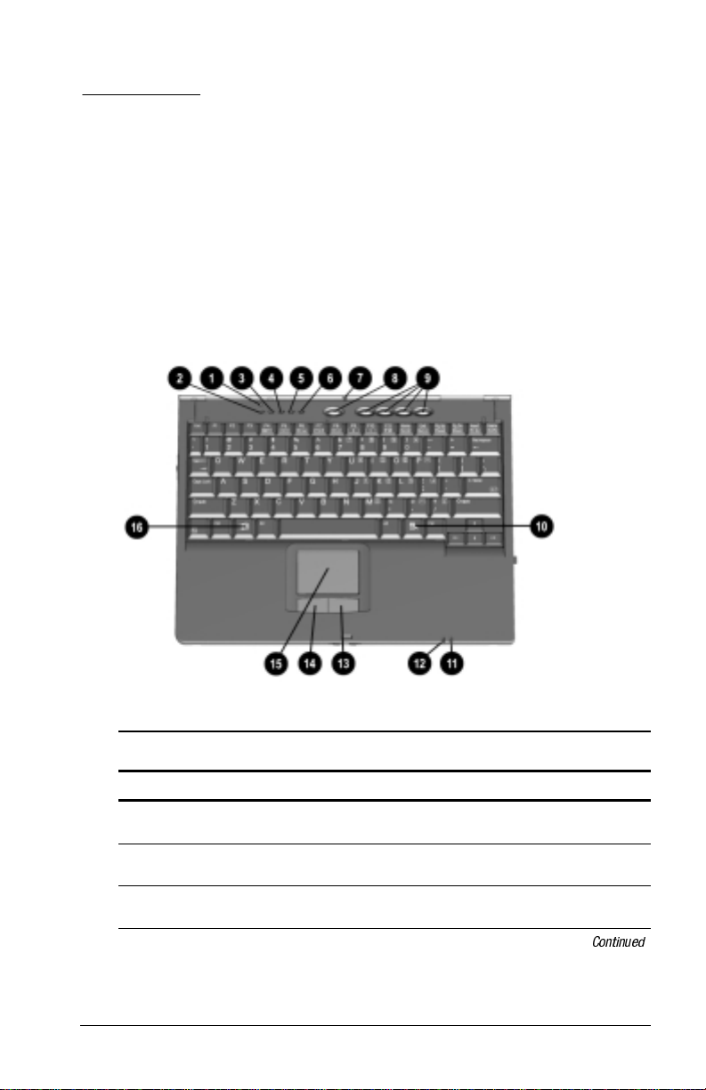
Top Components
Top Components
Component Function
Display switch Turns off the computer display if the
1
Hard drive light On: The primary hard drive is being
2
Diskette drive light On: The external diskette drive is being
3
computer is closed while on.
accessed.
accessed.
Taking a Look at the Computer
Continued
1-1
Page 11

Top Components
Continued
Component Function
Num lock light On: Num lock is on and the embedded
4
Caps lock light On: Caps lock is on.
5
Scroll lock light On: Scroll lock is on.
6
Internal microphone Supports audio input when the display is
7
Suspend button** Initiates and exits Suspend.* When pressed
8
Easy Access Buttons (available on
9
select models)
Windows application key Displays shortcut menu for item beneath
:
Battery light On: The battery pack is charging.
;
Power/suspend light On: Power is turned on.
<
Right-click button Functions like the right-click button of an
=
Left-click button Functions like the left-click button of an
>
TouchPad Moves the mouse cursor, selects, and
?
Microsoft logo key Displays Windows Start menu.
@
*In Windows 98 the term
**In Windows 98 the term
replaces the term
Standby
sleep button
numeric keypad is enabled.
open or closed.
with the Fn key, initiates Hibernation.
Allow direct access to predefined files,
programs, or websites.
mouse cursor.
Blinking: The battery pack that is the only
available power source has reached a
low-battery condition.
Off: Power is turned off.
Blinking: Computer is in Suspend.*
The power/suspend light also blinks
NOTE:
if a battery pack that is the only source of
power available to the computer reaches a
critical low-battery condition while
Hibernation is disabled.
external mouse.
external mouse.
Used with the TouchPad, drags and
highlights.
activates.
Suspend.
replaces the term
suspend button.
1-2
Taking a Look at the Computer
Page 12
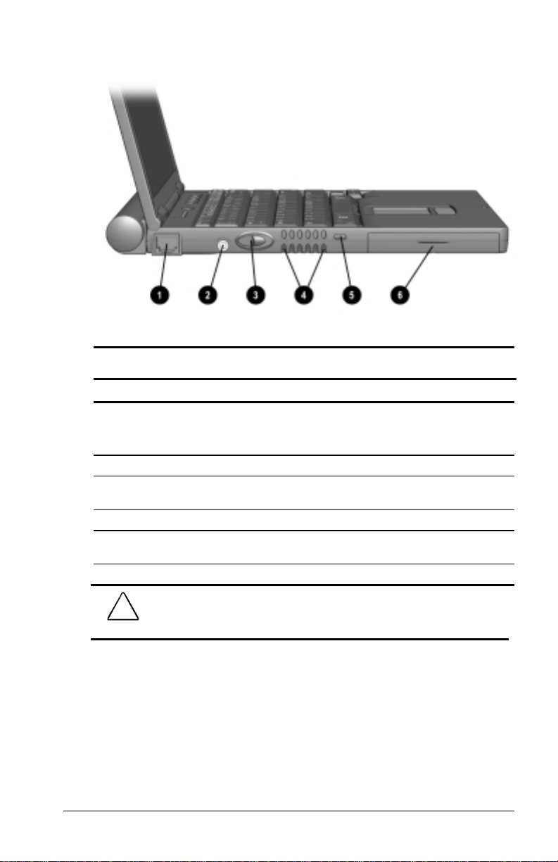
Left Side Components
Left Side Components
Component Function
RJ-45 jack* Connects the network cable.
1
Power connector Connects the AC power adapter.
2
Power button Turns the computer on or off or exits
3
Vents Cools internal components.
4
Security cable slot Attaches an optional security cable to the
5
Hard drive bay Holds primary hard drive.
6
!
damage to the equipment, do not plug a telephone cable into
the Ethernet RJ-45 jack.
*WARNING:
To reduce the risk of electric shock, fire, or
A network cable is included with
NOTE:
network models.
Suspend.
computer.
Taking a Look at the Computer
1-3
Page 13
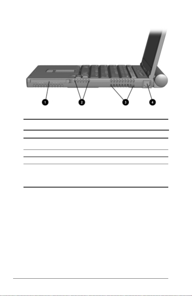
Right Side Components
Right Side Components
Component Function
PC Card slot Supports 32-bit (CardBus) and 16-bit
1
Air intake vents Cool internal components.
2
Air exhaust vents Cool internal components.
3
RJ-11 jack (internal modem models
4
only)
PC Cards.
Connects the modem cable to an internal
modem.
A modem cable is included with
NOTE:
internal modem models.
1-4
Taking a Look at the Computer
Page 14

Front Components
Component Function
Display release latch Opens the computer.
1
Stereo speaker/headphone jack Connects stereo speakers, headphones, or
2
Microphone jack Connects a single sound
3
Power/suspend light On: Power is turned on.
4
Battery light On: A battery pack is charging.
5
Front Components
headset audio.
channel microphone.
Off: Power is turned off.
Blinking: Computer is in Suspend.
The power/suspend light also blinks if
NOTE:
a battery pack that is the only source of
power available to the computer reaches a
critical low-battery condition while
Hibernation is disabled.
Blinking: A battery pack that is the only
available power source has reached a
low-battery condition.
Taking a Look at the Computer
1-5
Page 15

Rear Components
Component Function
USB connector Connects USB devices.
1
Serial connector Connects a serial device.
2
Parallel connector Connects a parallel device.
3
External monitor connector Connects an external monitor, overhead
4
Infrared port Links to another IrDA-compliant device for
5
Rear Components
projector, or TV adapter.
wireless communication.
1-6
Taking a Look at the Computer
Page 16
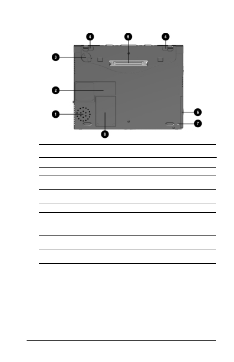
Bottom Components
Component Function
Speaker Produces sound.
1
Serial number Identifies computer; needed when you call
2
Real-time clock battery Provides battery power to automatically
3
Battery latches Releases the primary battery pack.
4
220-pin docking connector Connects the computer to a docking base.
5
Hard drive release latch Releases a hard drive from the hard drive
6
Hard drive security screw Secures hard drive in computer hard drive
7
Modem compartment Provides access to the internal modem
8
Bottom Components
Compaq customer support.
display the date and time.
bay.
bay.
(modem models only).
Taking a Look at the Computer
1-7
Page 17
External Diskette Drive
The computer comes with an external diskette drive which can be
used with floppy diskettes.
Electrostatic discharge can damage electronic
IMPORTANT:
CAUTION:
components. Before touching the diskette drive, ensure that you
are discharged of static electricity by touching a grounded metal
object. Refer to Appendix C, Electrostatic Discharge.
If you are using Windows 95, Windows 98, or
Windows NT 4.0 preinstalled by Compaq, you do not need to turn
off the computer before connecting or disconnecting the external
diskette drive to the computer. If you installed Windows 95,
Windows 98, or Windows NT 4.0 that you purchased separately,
you must obtain additional software from Compaq to support
connecting or disconnecting the drive while the computer is on or
in Suspend (Standby). For more information about the software,
refer to the Compaq Internet site at http://www.compaq.com.
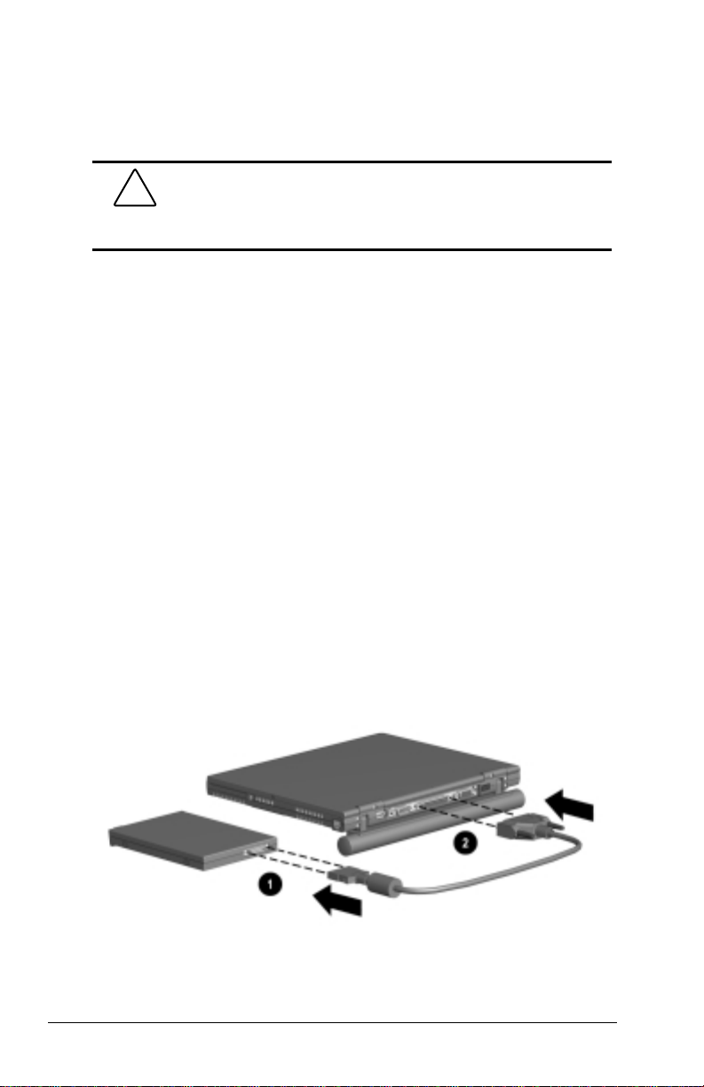
Connecting the Diskette Drive
To connect the external diskette drive to the computer:
1. Attach the small end of the drive cable to the external diskette
drive 1.
2. Attach the large end of the drive cable to the parallel port on
the rear of the computer 2.
1-8
Taking a Look at the Computer
Page 18
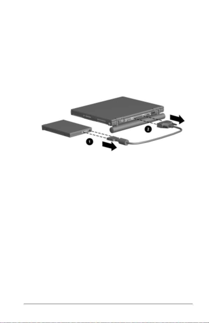
Disconnecting the Diskette Drive
To disconnect the external diskette drive from the computer:
1. Remove the diskette from the diskette drive.
2. Unscrew the small end of the drive cable from the external
diskette drive 1.
3. Unscrew the large end of the drive cable from the parallel port
on the rear of the computer 2.
Versatile Battery Pack
The primary battery pack is a multifunctional feature of the
computer. In addition to providing portable power, it
Creates a comfortable tilt for working at the keyboard. Fold
■
the battery pack back and under the computer.
Provides a cover for the rear connectors. Place the battery pack
■
in a straight position while the computer is lying flat.
Taking a Look at the Computer
1-9
Page 19
chapter
2
USING THE KEYBOARD
Using the Pointing Device
The built-in TouchPad functions with any software that
supports a Microsoft-compatible mouse.
NOTE: If you are using software that does not support a
Microsoft-compatible mouse, select Advanced
Options in Computer Setup, then select the Disable Multiple
Pointing Devices check box. For more information on running
Computer Setup, please refer to Chapter 14.
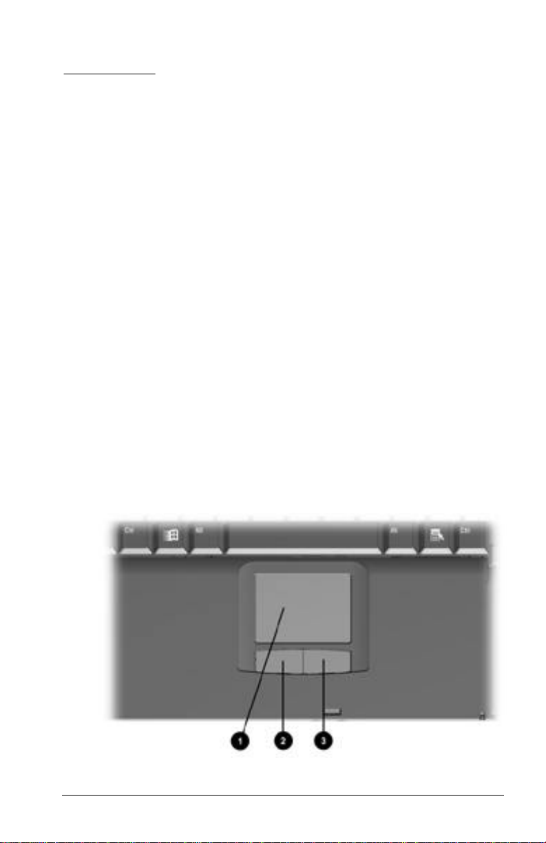
Identifying Keyboard Components
àDevice
1 TouchPad 3 Right-click button
2 Left-click button
Using the Keyboard 2-1
Page 20

Navigating with the TouchPad
TouchPad Procedures
Task Procedure
Move the mouse pointer Move your finger directionally
Increase or decrease cursor speed Increase or decrease finger speed
Right-, left-, or double-click Press the right- or left-click button as
Highlight an item* Press down on the TouchPad as
Select text or an object* Position the mouse pointer over the
Activate a selection* Position the mouse pointer over the
Select, then drag and drop an item* Press down on the TouchPad as
*To perform this task exactly as you would with an external mouse, use the
left-click button like an external mouse left-click button.
across the TouchPad surface.
across the TouchPad surface.
you would the corresponding click
button on an external mouse.
you move the mouse pointer over
the item.
highlighted text or object, then
quickly tap the TouchPad once.
selection, then quickly tap the
TouchPad twice.
NOTE: To select and activate a
preference, first tap the preference
once to select it, then tap the
preference twice to activate it.
you move the mouse pointer over
the item, then drag the item to the
new location. To drop the item,
release the pressure.
Setting TouchPad Preferences
To access all TouchPad features and settings including mouse
trails, cursor speed, double-click pace, and Windows 98
single-click mode, select Start
Panel
àMouse.
2-2 Using the Keyboard
à SettingsàControl
Page 21
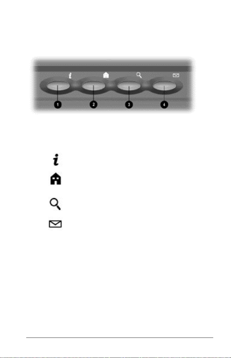
Easy Access Buttons
The Easy Access Buttons located at the top of your keyboard
provide quick access to the Internet. Before using these
buttons, you must have Internet service.
The Easy Access Buttons are programmed to do the following:
Easy Access Buttons
Component Function
1
2
3
4
To use the Easy Access Buttons
n You must be connected to the Internet. Until you set up
your Internet Service Provider (ISP), each Easy Access
Button will launch the Compaq Internet Setup process.
n You do not have to be connected to your ISP to add,
change, or delete schemes.
n You can also connect an external Compaq keyboard to the
computer. When an external Compaq keyboard that has
seven or eight Internet buttons is connected to your
computer, the first four buttons on the external keyboard
will automatically default to the Easy Access Buttons.
Information —Direct link to Compaq
Armada mobile user information for quick
answers to your computer questions.
Home—Internet start point. Connects to a
personalized Web page filled with local
weather, news, sports, and financial
information.
Search—Opens the AltaVista search
engine website which helps you locate
information on the Internet.
Email—Provides one-touch access to your
default Email application for sending and
reading your Email.
Using the Keyboard 2-3
Page 22

Adding Easy Access Buttons Schemes
Schemes are a collection of up to four button assignments that
you define. You can add additional schemes so that the
buttons will perform different functions depending on which
scheme is currently selected. There is no limit to the number
of schemes that can be added, but the buttons will only work
for the scheme that is currently selected.
To add a new scheme:
1. Double-click the Easy Access Buttons icon located on the
Windows Taskbar
OR
Click Start
Keyboard
2. Click the Add button.
3. In the scheme box, type the name of the scheme to be
added.
4. In the Button Name box, type the new name for the button
being assigned.
5. In the Button Assignment box, type the name for the
button being assigned.
6. In the Button Assignment box, enter the item to which you
are assigning the button. To enter a button assignment
n Type the file path or website address in the Button
Assignment box.
or
n Use standard Windows procedures to copy a file path or
website address elsewhere, then paste it onto the Button
Assignment box.
à Settings à Control Panel à double-click
à click the Easy Access Buttons tab.
or
n Select the browse button, then double-click the item.
When the item displays in the File name box, select OK.
7. Repeat Steps 4 and 5 for each of the Easy Access Buttons
you want to include in the new scheme.
8. Select the Apply or OK button.
2-4 Using the Keyboard
Page 23

Changing Easy Access Buttons Schemes
To select a different scheme:
1. Double-click the Easy Access Buttons icon located on the
Windows Taskbar
OR
Click Start
Keyboard
2. In the Scheme drop-down list in the scheme box, select the
scheme that contains the button name or assignment being
changed.
3. In the Button name column, select the icon of the button
being changed.
4. To change the button name—select the Edit button beside
the Button Name box, then type the new name into the
Button Name box.
5. To change the button assignment—Enter the item to which
you are assigning the button in the Button Assignment
box. to enter a button assignment
n Type the file path or website address in the Button
Assignment box.
or
n Use standard Windows procedures to copy a file path or
website address elsewhere, then paste it onto the Button
Assignment box.
à Settings à Control Panel à double-click
à click the Easy Access Buttons tab.
or
n Select the browse button, then double-click the item.
When the item displays in the File name box, select OK.
6. Select the Apply or OK button.
Using the Keyboard 2-5
Page 24

Deleting Easy Access Buttons Schemes
NOTE: The default schemes can not be deleted. Only the
schemes defined by you can be deleted.
To delete a scheme:
1. Double-click the Easy Access Buttons icon located on the
Windows Taskbar
OR
Click Start
Keyboard
à Settings à Control Panel à double-click
à click the Easy Access Buttons tab.
2. In the Scheme drop-down list box, select the name of the
scheme you want to delete.
NOTE: Schemes must be deleted one at a time.
3. Click the Delete button.
4. Click OK.
Programming the External Keyboard Internet Buttons
If a Compaq external keyboard with seven or eight Internet
buttons is connect to your computer, the first four Internet
buttons automatically default to the Easy Access Buttons
schemes. You can program the remaining external keyboard
Internet buttons or change the Easy Access Buttons to match
the first four Internet buttons on the external keyboard.
To program the remaining external keyboard Internet buttons:
1. Double-click the Easy Access Button icon located on the
Windows Taskbar
OR
Click Start
Keyboard
à Settings à Control Panel à double-click
à click the Easy Access Buttons tab.
2. Click Internal and select the type of external keyboard you
have connected to the computer.
3. Click on Add, then enter the name of the filenames,
programs, or websites you want assigned to the remaining
buttons on the external keyboard.
4. Click Apply.
To change the Easy Access Buttons on the computer to match
the first four button schemes on the External keyboard:
2-6 Using the Keyboard
Page 25

1. Double-click the Easy Access Button icon located on the
Windows Taskbar
OR
Click Start
Keyboard
à Settings à Control Panel à double-click
à click the Easy Access Buttons tab.
2. Click Internal.
3. Click on Add, then enter the name of the filenames,
programs, or websites you want assigned to the four Easy
Access Buttons.
4. Click Apply. The Easy Access buttons on the computer are
programmed to be the same as the first four buttons on the
external keyboard.
Using Hotkeys
Hotkeys are preset combinations of the Fn key 1 plus a second
key that take you to frequently used system functions. The
icons on the function keys
n To use hotkeys on an external keyboard which does not
have an
Fn key, press the Scroll Lock key twice, then the
second key only of the hotkeys combination. For example,
to use the
Fn+F3 hotkeys, press Scroll Lock+Scroll Lock+F3 .
(F1-F10) 2 represent these functions.
NOTE: The Fn+F6 (Initiate Quick Controls) hotkeys cannot be
used on an external keyboard connected through a USB
connector.
n To close a window opened with hotkeys, use standard
Windows procedures or press the hotkeys again.
Using the Keyboard 2-7
Page 26

Hotkeys Quick Reference
Task Hotkeys
Switch the display and image Fn+F4
Adjust system volume Fn+F5
Initiate Quick Controls Fn+F6
Set a power conservation level Fn+F7
View battery charge status Fn+F8
Adjust screen brightness Fn+F10
Display system information Fn+Esc
Stretch text Fn+T
Switching the Display and Image
In Windows 95 or Windows NT 4.0 toggle Fn+F4 to switch
the image among the computer display, an external display,
and simultaneous display. The external display can be
connected through the external monitor connector.
In Windows 98 toggle
Fn+F4 to switch the image between the
computer display and an external display that is connected
through the external monitor connector.
n When MultiMonitor is enabled, press Fn+F4 to turn off the
external display and disable MultiMonitor.
2-8 Using the Keyboard
Page 27

n When MultiMonitor is disabled, toggle Fn+F4 to switch the
image among the computer display, the external display,
and simultaneous display.
Adjusting System Volume
n To adjust system volume with an onscreen slide button or
with the keyboard arrow keys, press
n To mute or restore volume
n Press Fn+F5+M
or
n Press Fn+F5, then select or clear the Mute checkbox.
Fn+F5.
Initiating Quick Controls
Quick Controls security features disable the keyboard and
pointing device and clear the screen. Before you can use
Quick Controls, you must set a power-on password and enable
Quick Control preferences. For instructions, refer to Chapter
11.
n To initiate Quick Controls manually, press Fn+F6.
n To exit Quick Controls, enter your power-on password.
The
Fn+F6 hotkeys cannot be used on an external keyboard
connected through a USB connector on the computer or an
optional docking base.
Using the Keyboard 2-9
Page 28

Setting a Power Conservation Level
In Windows 98 press Fn+F7 to open the Power Schemes
window.
In Windows 95 or Windows NT 4.0 press
Fn+F7 to open the
Battery Conservation Settings window.
n To select a preset battery conservation level, choose
among
n High—Maximizes running time from a single charge.
n Medium—Balances system performance with running
time.
n None (Drain)—Runs the computer at full power.
n For information about the Custom level, refer to “Using
Power Preferences” in Chapter 3.
Viewing Battery Charge Status
Press Fn+F8 to view the status of all installed battery packs.
Battery packs are listed by location.
n To display the location of a listed battery pack, select the
corresponding battery icon.
n A lightening bolt icon beside a battery icon indicates that
the battery pack in that location is charging.
Adjusting Screen Brightness
Press Fn+F10 to adjust the brightness of the computer screen
with an onscreen slide button or with the arrow keys.
Displaying System Information
Press Fn+Esc to display information about system hardware
components and software version numbers.
NOTE: The number beside System BIOS is the version number
of your system ROM.
2-10 Using the Keyboard
Page 29

Stretching Text
When the computer is running MS-DOS under Windows and
the desktop area resolution is set lower than the display
resolution, press
Fn+T to toggle the image between Text
Stretch, which stretches the text to fill more of the screen, and
Regular. Text Stretch is the default. While Regular is selected,
a graphics accelerator cannot be enabled.
Enabling the Eurocurrency Symbol
Your computer can generate the Eurocurrency symbol when
pressing the
Alt Gr+4, 5, e, or u key combinations. The key
combination for your computer is dependent on the keyboard
for your country and the keyboard language settings in the
operating system. On keyboards without the
graphics) key, use the
Alt key to the right of the spacebar.
Alt Gr (alternate
Using the Embedded Numeric Keypad
Toggling the Keypad On and Off
n n To convert the embedded numeric keypad section 1 of the
computer keyboard to a numeric keypad, press
2.
Fn+Num Lk
n When the embedded numeric keypad is enabled, the
characters upper-right on the keypad keys are active
and the Num Lk light 3 is on.
n To disable the embedded numeric keypad, toggle
Fn+Num Lk.
n The embedded numeric keypad cannot be enabled while
an optional external keyboard or numeric keypad is
connected to the computer.
Using the Keyboard 2-11
Page 30

Operating the Keypad Keys as Standard Keys
To use the embedded numeric keypad keys as standard
keyboard keys while the keypad is enabled:
n Press and hold Fn to type in lowercase.
n Press and hold Fn+Shift to type in uppercase.
Enabling the Keypad at Startup
To set the computer to start up with the embedded numeric
keypad enabled:
1. Turn on or restart the computer, then press
blinking cursor appears in the upper-right corner of
the screen.
n To change the language, press F2 .
n For navigation instructions, press F1 .
2. Select Advanced
àDevice Options, then press Enter.
3. Toggle the field beside Num Lock State at Boot to On,
then press
F10 .
4. To save your preferences, close Computer Setup, and
restart the computer, select File
then press
Enter.
àSave Changes and Exit,
5. When you are prompted to confirm your action, press
2-12 Using the Keyboard
F10 when the
F10 .
Page 31

To disable the embedded numeric keypad at start up, repeat
the above procedure with the Num Lock State at Boot field
toggled Off.
NOTE: The embedded numeric keypad can be enabled or
disabled with
Fn+Num Lk in either startup state.
Using the Keyboard 2-13
Page 32

chapter
3
ANAGING POWER
M
Selecting a Power Source
!
WARNING:
shock, fire, or damage to the equipment:
Do not disable the power cord grounding plug. The
■
grounding plug is an important safety feature.
Plug the equipment into a grounded (earthed) electrical
■
outlet that is easily accessible at all times.
Disconnect power from the equipment by unplugging the
■
power cord from the electrical outlet.
Do not place anything on power cords or cables. Arrange
■
them so that no one may accidentally step on or trip over
them.
Do not pull on a cord or cable. When unplugging from the
■
electrical outlet, grasp the cord by the plug.
To reduce the risk of personal injury, electric
Managing Power
3-1
Page 33

Selecting a Power Source
Task Recommended Power Source
Charged battery pack inserted into
Work within installed software
applications
Charge a battery pack in the
computer
Calibrate a battery pack External power supplied through
Modify system software External power supplied through the AC Adapter
■
the computer
or
External power supplied through
■
AC Adapter
■
Optional docking base
■
Optional Automobile Power
■
Adapter/Charger or
Optional Aircraft Power Adapter
■
External power supplied through
AC Adapter
■
Optional docking base
■
Optional Automobile Power Adapter/Charger
■
AC Adapter
■
Optional docking base
■
3-2
Managing Power
Page 34

Beginning, Leaving, or Resuming Your Work
You will observe the power button , Suspend button ,
Fn
key !,
and the power/suspend light as you turn the computer on or off or
place it in
■
Suspend,
Suspend (Standby)
called
Standby
or
Hibernation.
in Windows 98, is an energy-saving
feature that reduces power to system components that are not
being used. When the computer is in Suspend (Standby), your
work is saved in random access memory (RAM) and the
screen is cleared.
■
Hibernation
is an energy-saving feature that saves all
information in RAM to a hibernation file on the hard drive,
then shuts down the computer.
If you are leaving your work, consider:
If you plan to resume shortly
—Initiating Suspend (Standby)
clears the screen, uses less power than leaving the computer on,
and your work returns instantly to the screen when you press the
suspend button. A fully charged battery pack can support Suspend
(Standby) for up to a week, but frequent charging and discharging
may shorten battery pack life.
If the computer will be disconnected from external power for
more than two weeks
—To extend the useful life of the battery
pack, shut down the computer, then remove the battery pack and
store it in a cool, dry place.
Managing Power
3-3
Page 35

If you plan to resume within two weeks
—Initiating Hibernation
clears the screen, saves your work to the hard drive, and uses less
power than Suspend (Standby). A fully charged battery pack
supports Hibernation indefinitely.
Beginning, Leaving, or Resuming Your Work
Task Procedure Result
Turn the computer on Press power button. Power/suspend* light turns
on.
Operating system loads.
Turn the computer off Click StartÆShut Down. Power/suspend* light turns
off.
Operating system closes
and turns off all power.
Computer turns off.
Press suspend
Initiate Suspend*
Exit Suspend*
Initiate Hibernation Press
Restore from Hibernation Press power button. Power/suspend* light turns
*In Windows 98 the term Standby replaces the term Suspend.
**In Windows 98 the term
■
button.**
or
Select Standby
■
(Windows 98 only) on
the Shut Down menu.
Press suspend
■
button.**
or
Press power button.
■
Fn +
button.**
sleep button
suspend
replaces the term
Power/suspend* light blinks.
System beeps twice.
Screen clears.
Power/suspend* light turns
on.
System beeps once.
Your work returns to the
screen.
Power/suspend* light turns
off.
System beeps twice.
Screen clears.
on.
System beeps once.
Your work returns to the
screen.
suspend button.
3-4
Managing Power
Page 36

Managing Low-Battery Conditions
Identifying Low-Battery Conditions
When a battery pack that is the only source of power available
■
to the computer reaches a low-battery condition
The system beeps 5 times.
■
The battery light blinks.
■
If the low-battery condition is not resolved, the computer will
■
enter a
critical
condition,
If Hibernation is enabled and the computer is on or in
■
Suspend (Standby)
initiates Hibernation. Hibernation is enabled by default.
If Hibernation is disabled and the computer is on or in
■
Suspend (Standby)
power/suspend light blinks. The computer remains
briefly
unsaved work is lost.
low-battery condition. In a
—The computer beeps twice, then
—The computer beeps twice, and the
in Suspend (Standby), then shuts down and your
critical
low-battery
Managing Power
3-5
Page 37

Resolving Low-Battery Conditions
If external power is available, do one of the following
■
Connect the computer to an electrical outlet with the AC
■
Adapter.
Dock the computer and mobile expansion unit in a docking
■
base that is connected to external power.
Plug an optional Automobile Power Adapter/Charger into
■
the power connector on the computer and into a vehicle
cigarette lighter receptacle.
Plug an optional Aircraft Power Adapter into the power
■
connector on the computer and into the in-seat power
supply available on some commercial aircraft.
NOTE:
An optional Aircraft Power Adapter can be used to run
the computer but cannot be used to charge a battery pack.
■
If a charged battery pack is available—
hut down the computer, then remove the discharged battery
s
pack and insert a charged battery pack.
■
If neither external power nor a charged battery pack is
available
Press
■
or
—
Fn
suspend button to initiate Hibernation
+
Save your work,
—
Save your work, then shut down the computer.
■
Restoring from Hibernation After Resolving
a Critical Low-Battery Condition
Press the power button. If the computer does not have
enough power to restore your work,
1. Press
2. Attach a charged battery pack or connect the computer to
3. Press the power button.
3-6
Managing Power
Ctrl+Alt+Del
external power.
to abort the restoration.
Page 38

Charging a Battery Pack
When a battery pack is installed in the computer or an optional
Battery Charger or docking base, the battery pack is charged
whenever external power is available.
NOTE:
Charging may be delayed if a battery pack is new, has not
been used for 2 weeks or more, or is much warmer or cooler than
a comfortable room temperature.
If you are charging the battery pack in the computer—
■
External power can be supplied to the computer from an
■
external power source.
NOTE:
An optional Aircraft Power Adapter cannot be used to
charge a battery pack.
The battery light, shown below, turns on while the battery
■
pack is charging and turns off when the battery pack is
fully charged.
Managing Power
3-7
Page 39

To increase the accuracy of all battery charge displays
■
Allow a battery pack to discharge to the low-battery level
■
through normal use before charging it.
When you charge a battery pack, charge it fully.
■
Before charging a new battery pack or a battery pack that
■
has not been used for 2 weeks or more, calibrate the new
battery pack or check the calibration on the unused
battery pack.
Monitoring the Charge in a Battery Pack
—
NOTE:
The references in Windows 98 battery charge displays to a
“standard APM battery pack” apply to all battery packs that can be
used in the computer.
Using the Battery Charge Level Lights
The battery quick check feature enables you to monitor the charge
in the primary battery pack.
To display the percent of a full charge remaining in a battery
■
pack, press the button on the battery pack.
Each battery charge level light represents a percentage of a full
■
charge. For example, when all lights are on, the battery pack is
fully charged.
Using the Battery Status Tab
To access the Battery Status tab, select StartÆSettingsÆControl
PanelÆpower icon (named Power, Power Management, Compaq
Power Properties, or Power Options, depending on your operating
system)ÆBattery Status tab.
To display the location of a listed battery, select the
■
corresponding battery icon.
A lightning bolt icon beside a battery icon indicates that the
■
battery pack in that location is charging.
3-8
Managing Power
Page 40

Using the Battery Meter or Power Meter Icon
The battery meter icon, called the power meter icon in
Windows 98 and Windows 2000 Professional, indicates whether
the computer is running on external power or on a full, half-full,
or nearly discharged battery pack.
To display the battery meter icon in the taskbar
In Windows 95
■
PanelÆPowerÆBattery Status tab, then select the Show
Battery Meter on the Taskbar check box.
In Windows 98
■
PanelÆPower ManagementÆPower Meter tab, then select the
Show Power Meter on the Taskbar check box.
In Windows NT 4.0
■
taskbar by default. In addition, you can select
StartÆSettingsÆControl PanelÆCompaq Power
PropertiesÆAdvanced tab.
In Windows 2000 Professional
■
StartÆSettingsÆControl PanelÆPower OptionsÆPower
Meter tab, then select the Show Battery Meter on the Taskbar
check box.
When the battery meter or power meter icon is displayed in the
taskbar, the icon can also be used as follows.
select StartÆSettingsÆControl
select StartÆ SettingsÆControl
the battery meter icon displays in the
select
In Windows 95, Windows 98, and Windows 2000
Professional
Task Procedure
View the total battery power remaining in
the system.
Enable/disable an on-screen critical lowbattery warning.
Access the Power tab in the Power
Properties window.
Open battery meter in a popup window. Double-click the icon.
Display charge information as a percent of
a full charge or as the run time remaining.
Rest the cursor over the icon.
Left-click the icon, select or clear the
Enable Low Battery Warning check box,
then select OK.
Right-click the icon, select Adjust Power
Properties, then press
Left-click the icon, then select your
preference in the popup window.
Managing Power
Enter.
3-9
Page 41

In Windows NT 4.0
Task Procedure
View the total battery power remaining in
the system.
Open the Compaq Power Properties
window.
Rest the cursor over the icon.
Double-click or right-click the icon.
Using the Power or Power Meter Tab
The power tab, called the power meter tab in Windows 98 and
Windows 2000 Professional, is available in Windows 95,
Windows 98, and Windows 2000 Professional.
To access the tab
■
In Windows 95
■
select StartÆSettingsÆControl Panel
PowerÆPower tab.
In Windows 98
■
select StartÆSettingsÆControl Panel
Power ManagementÆPower Meter tab.
In Windows 2000 Professional
■
select
StartÆSettingsÆControl PanelÆPower OptionsÆPower
Meter tab.
To view the combined percent of total power remaining in all
■
battery packs in the system, clear the Show the Status of All
Batteries check box.
To view the percent of total power remaining in each battery
■
pack in the system, select the Show the Status of All Batteries
check box.
Æ
Æ
3-10
Managing Power
Page 42

Calibrating a Battery Pack
Calibration increases the accuracy of all battery charge displays.
The calibration utility supports all battery packs that can be used
in the computer.
Use the calibration utility both to check the calibration of a battery
pack and to calibrate or recalibrate a battery pack.
A battery pack cannot be calibrated unless the utility reports
■
that it needs calibration.
A new battery pack can be charged, then used to run the
■
computer before the battery pack is calibrated. However,
the amount of charge in the new battery pack cannot be
reported accurately until the new battery pack has been
calibrated.
Check the calibration of a used battery pack periodically
■
and whenever battery charge displays seem inaccurate.
While a battery pack is being calibrated, it is fully charged,
■
then fully discharged.
A battery calibration icon in the taskbar displays an Up
■
arrow during the charge phase and a Down arrow during the
discharge phase.
A calibration cannot resume if the calibration is stopped or
■
if the computer is shut down during a calibration. An
interrupted calibration must be restarted.
After calibration, a battery pack must be charged before it
■
can be used to run the computer.
The calibration utility calibrates one battery pack at a time
■
and can run in the background as you use the computer
or overnight.
CAUTION:
remains connected to AC power throughout a calibration.
To prevent loss of work, ensure that the computer
Managing Power
3-11
Page 43

Running a Calibration
1.
To check the calibration of a battery pack—
Attach the
battery pack to the computer or insert a battery pack into the
MultiBay of the mobile expansion unit. If you insert the
battery pack into the expansion unit's MultiBay, connect the
computer and expansion unit system to external power.
To calibrate a battery pack—
Attach the battery pack to the
computer. Then connect the computer to external power with
the AC Adapter or dock the computer and mobile expansion
unit in a docking base that is connected to external power
2. Access the Battery Calibration tab.
In Windows 95
■
select StartÆSettingsÆControl
PanelÆPowerÆCompaq Power tab.
In Windows 98
■
select StartÆSettingsÆControl
PanelÆPower ManagementÆCompaq Power tab.
In Windows NT 4.0
■
select StartÆSettingsÆControl
PanelÆCompaq Power PropertiesÆCompaq Power tab.
In Windows 2000 Professional
■
select
StartÆSettingsÆControl PanelÆPower OptionsÆCompaq
Power tab.
3. Select the battery to be calibrated. If the battery needs to be
calibrated, the Calibrate button will be displayed.
4. Click the Calibrate button to start calibration.
Once the calibration utility starts, you can close the Power Options
Properties dialog box and monitor the progress of the calibration
through the icon in the system tray.
Stopping a Calibration
Shut down the computer or select the Stop Calibration button on
the Compaq Power tab. The Stop Calibration button is visible only
during a calibration.
3-12
Managing Power
Page 44

Changing the Primary Battery Pack
The primary battery pack is the battery pack attached to the
computer.
NOTE:
For information on using a battery pack in the mobile
expansion unit MultiBay, refer to Chapter 5.
CAUTION:
Hibernation or shut down power before removing or installing
the battery pack. Failure to do so will result in loss of
information.
WARNING:
to the battery pack, do not crush, puncture, or incinerate the
battery pack or short the metal contacts. Do not attempt to
open or service the battery pack.
If the computer is on, you must initiate
To reduce the risk of personal injury or damage
Removing the Primary Battery Pack
1. If the computer is on, save your work and initiate Hibernation
or shut down the computer.
2. Turn the computer bottom side up and tilt the battery pack so
it lies flat (covering all ports on the rear of the computer).
3. Slide in the two battery latches toward each other.
Managing Power
3-13
Page 45

4. Rotate the battery pack 90 degrees , and lift up the battery
pack from the computer .
Installing the Primary Battery Pack
1. If the computer is on, save your work and initiate Hibernation
or shut down the computer.
2. Turn the computer bottom side up.
3. Slide in the two battery latches toward each other.
3-14
Managing Power
Page 46

4. Push the battery pack onto the computer until the contacts
connect , and rotate the battery pack 90 degrees toward the
back of the computer .
5. Slide the two battery latches out (away from each other) !.
Storing the Battery Pack
CAUTION:
expose it to high temperatures for extended periods of time.
If the computer will be unused and unplugged from an external
power source for more than two weeks, remove and store the
battery pack(s).
Proper storage procedures reduce the self-discharge rate of a
battery pack. Store a battery pack in a cool, dry place within the
following temperature ranges.
To prevent damage to a battery pack, do not
Managing Power
3-15
Page 47

Recommended Battery Pack Storage Temperatures
Storage Time Temperature Range°F Temperature Range
°C
Less than 1 month 32°–122° 0°–50°
No more than 3
months
Unlimited 32°– 86° 0°–30°
32°–104° 0°–40°
Using Power Preferences
You can increase, decrease, and allocate the power used by the
computer by setting power preferences.
Increasing power increases performance, while decreasing
■
power conserves energy and extends the running time from a
battery pack.
By decreasing power to unused components and functions,
■
you can allocate more power to the components and functions
that you are using.
Many power preferences are
A timeout is the period of inactivity before the system initiates
■
timeout
settings.
a power change or reduces power to a component. For
example, the computer is preset to initiate Suspend (Standby)
after a period of inactivity. The time interval between when
you stop using the computer and the onset of computerinitiated Suspend (Standby) is a Suspend (Standby) timeout.
Depending on your operating system, you can set timeouts
■
that are specific to various conditions, components, or
procedures as well as specify the duration of those timeouts.
For additional power options, refer to your operating system
documentation. For a summary of battery conservation settings
that extend the running time from a single charge, refer to
“Conserving Battery Power” later in this chapter.
The following tables list power procedures that are not described
in your operating system documentation.
3-16
Managing Power
Page 48

Setting Power Preferences in Windows 95 or
Windows NT 4.0
Setting Power Preferences in Windows 95 or Windows NT 4.0
Preferences Procedure from Control Panel
Select a preset level of power use
that applies whenever the computer
is running on a battery pack.
A battery conservation level
NOTE:
can also be displayed and selected
with the
Fn+F7
hotkeys.
Create a level of power use that
applies settings for the following
whenever the computer is running
on a battery pack:
Suspend timeout
■
System idle timeout
■
Processor speed
■
Screen brightness
■
Screen save
■
In Windows NT, create a general
level of power use that applies
whenever the computer is running
on external AC power. You can enter
settings for
Screen save timeout
■
Hard drive timeout
■
Energy-saving monitor timeout
■
Enable/disable low-battery warning
beeps.
Select Power (or Compaq Power in Windows
NT)ÆBattery Conservation Settings tab, then
select a conservation level:
High provides maximum battery conservation.
■
Medium balances battery conservation and
■
system performance.
None (drain) results in maximum battery drain
■
because battery conservation is turned off.
Recommended only for discharging the
battery pack.
Select Power (or Compaq Power in Windows
NT)ÆBattery Conservation Settings tab. Select
Custom, then enter your preferences.
Although a battery conservation level can be
NOTE:
displayed and selected with the
Fn+F7
Custom level preferences must be entered on the
Battery Conservation Settings tab.
1. Select Compaq PowerÆAC Energy Saver
tab.
2. Select the AC Energy Saver On button.
3. To set a screen save timeout, select a
timeout in the Screen Save drop-down list.
4. To set a hard drive timeout, select a timeout
in the Hard Disk Idle drop-down list.
5. To enable an external monitor to enter a
low-power mode following a screen save
timeout, select the Energy Save Monitor
check box.
You will not be logged off a network when
NOTE:
the monitor enters low-power mode.
Select Power (or Compaq Power in Windows
NT)ÆBattery Conservation Settings tab, then
check the box to turn beeps on or uncheck the box
to turn beeps off.
hotkeys,
Continued
Managing Power
3-17
Page 49

Setting Power Preferences in Windows 95 or Windows NT 4.0
Continue
d
Preferences Procedure from Control Panel
Set Hibernation timeout. Select Power (or Compaq Power in Windows NT)
Hibernation tab, then select a timeout from the
Æ
Timeout drop-down list.
This setting does not affect system -initiated
NOTE:
Hibernation during a critical low-battery condition.
Exit Suspend after a user-selected
timeout.
Set computer to initiate Hibernation
rather than Suspend.
In Windows 95, turn off power to an
optional PC Card modem.
Change location of Hibernation file. Select Power (or Compaq Power in Windows NT)
Enable/Disable Hibernation. Select Power (or Compaq Power in Windows NT)
Select Power (or Compaq Power in Windows NT)
Resume Timer tab. Select the Enabled check
Æ
box, then select a date from the Date drop -down
list and a time from the Time drop -down list.
Select Power (or Compaq Power in Windows NT)
Hibernation tab, then select Standby in the
Æ
Timeout drop-down list.
Select PowerÆPC Card Modems tab, then select
Turn Off Power to PC Card Modem When Not in
Use check box.
Hibernation tab, then select the new location
Æ
from the Drive for Hibernation File drop -down list.
Hibernation tab, then check the box to enable
Æ
Hibernation or uncheck the box to disable
Hibernation.
CAUTION:
low-battery condition while Hibernation is turned
off, unsaved work can be lost.
If the computer reaches a critical
3-18
Managing Power
Page 50

Setting Power Preferences in Windows 98 or Windows
2000 Professional
To access most power settings
—Select StartÆSettingsÆControl
PanelÆPower Management (or Power Options for Windows 2000
Professional). For information about setting all Power
Management settings except the following, refer to your
Windows 98 or Windows 2000 Professional documentation.
CAUTION:
condition while Hibernation is turned off, unsaved work will
be lost.
To enable or disable hibernation
If the computer reaches a critical low-battery
—Select the hibernation tab,
then check the box to enable Hibernation or uncheck the box to
disable Hibernation.
To set a screen brightness level that applies when the
computer is running on a battery pack
—Select Power
Management (or Power Options for Windows 2000
Professional)ÆBattery Conservation Settings tab, then select a
percent from the Brightness drop-down list.
If you are accustomed to running Windows 95 or
Windows NT 4.0 on a Compaq portable computer
—You will
find most of the power options you formerly accessed in Power
Properties in the Windows 98 Power Management Properties
window or the Windows 2000 Professional Power Options
window. However, in Windows 98 and Windows 2000
Professional
Processor speed is managed by the operating system.
■
The easiest way to turn off power to a PC Card is to remove
■
the PC Card.
The
■
The preferences you formerly set on the Resume Timer tab
■
hotkeys open the Power Schemes window.
Fn+F7
can be set at StartÆProgramsÆAccessoriesÆSystem
ToolsÆScheduled Tasks.
Managing Power
3-19
Page 51

Turning Auto Insert Notification On or Off
When using the computer with the mobile expansion unit, auto
insert notification runs a CD-ROM or DVD-ROM on insertion in
the expansion unit MultiBay, but drains power and prevents
system-initiated Suspend (Standby). To turn off auto insert
notification:
In Windows 95 or Windows 98
■
select StartÆSettings
Control PanelÆSystemÆDevice ManagerÆCD-ROM
Properties. Clear the CD-ROM Auto Insert Notification
check box.
In Windows NT 4.0
■
select StartÆSettingsÆControl
PanelÆCompaq PowerÆBattery Conservation Settings tab.
Clear the CD-ROM Auto Insert Notification check box.
To turn on auto insert notification, access the CD-ROM Auto
Insert Notification check box as instructed above, then select the
check box.
Changing the Processor Performance Mode
(Available on Select Models)
Computer models that provide Intel Pentium III with SpeedStep
technology allows you to enable an automatic change in processor
speed when the power source changes between AC power and
battery power.
Æ
Æ
The SpeedStep technology offers two preset performance modes:
■
In Maximum Performance mode,
the processor runs at full
speed to provide maximum performance.
■
In Battery Optimized mode,
the processor runs at a reduced
speed to provide optimal balance between energy conservation
and performance.
The computer can run in either performance mode while it is
running on AC power or on battery power.
3-20
Managing Power
Page 52

Changing Performance Modes
Before the performance mode changes from Battery
Optimized to Maximum Performance mode in Windows 95 or
Windows NT 4.0
—You are prompted to restart the computer.
The restart selection on the prompt restarts the computer and
returns your work to the screen.
It is not necessary to restart the computer to change from
Battery Optimized to Maximum Performance mode in
■
Windows 98
or from
Maximum Performance to Battery Optimized mode in any
■
operating system.
Combining Performance Modes with Other Power Settings
The SpeedStep technology performance modes are independent of
all other power settings available on the computer except the
Custom processor speed settings available in Windows 95 and
Windows NT 4.0.
In Windows 95 or Windows NT 4.0 only
Custom processor speed settings can be set by selecting
■
—
StartÆSettingsÆControl PanelÆPower or Compaq Power
PropertiesÆBattery Conservation Settings tabÆCustom.
The Custom processor speed applies any time the computer is
■
running on battery power.
Setting SpeedStep Preferences
If the SpeedStep window and icon are not accessible, they
NOTE:
may be disabled in Computer Setup. To enable the window and
icon, refer to Chapter 14 in this guide.
Using the SpeedStep Window
To open the SpeedStep window from the desktop
In Windows 95 or Windows NT 4.0,
■
StartÆProgramsÆIntel SpeedStep technology.
In Windows 98,
■
select StartÆSettingsÆControl
PanelÆPower MangementÆIntel SpeedStep technology tab.
select
—
Managing Power
3-21
Page 53

Setting SpeedStep Preferences
Preference Procedure
Assign a performance mode that
applies any time the computer is
running on battery power.
Assign a performance mode that
applies any time the computer is
running on AC power.
Set the computer to change
between the assigned power
modes whenever the power
source changes.
Set the computer to prompt for
confirmation before initiating a
performance mode change.
Set the computer to remain in the
same performance mode even if
the power source changes.
Turn off the audible alert of a
performance mode change.
Set the computer to change
automatically between Maximum
Performance mode while running
on AC power and Battery
Optimized mode while running on
battery power
and
Disable all settings in the main
SpeedStep window.
Select a performance mode from
the drop-down list under Running on
Batteries, then select OK.
Select a performance mode from
the drop-down list under Plugged In,
then select OK.
Select the checkbox for
Automatically Change Performance
When the Power Source Changes,
then select OK.
1. Select the checkbox for
Automatically Change
Performance When the Power
Source Changes.
2. Select the checkbox for Ask me
Before Automatically Changing
Performance.
3. Select OK.
Select the same performance mode
from the drop-down lists for Running
on Batteries and Plugged In, then
select OK.
Select the Advanced button, then:
1. Select the checkbox for Disable
Audio Notification When
Performance Changes.
2. Select OK in the Advanced
window.
3. Select OK or Apply in the main
SpeedStep window.
Select the Advanced button, then.
1. Select the checkbox for Disable
Intel SpeedStep Technology
Control.
2. Select OK in the Advanced
window.
3. Select OK or Apply in the main
SpeedStep window.
Continued
3-22
Managing Power
Page 54

Setting SpeedStep Preferences
Continued
Preference Procedure
Enable all settings in the main
SpeedStep window.
Remove the SpeedStep icon from
the taskbar.
Select the Advanced button, then:
1. Clear the checkbox for Disable
2. Select OK in the Advanced
3. Select OK or Apply in the main
NOTE:
may be necessary to restart the
computer after completing this
procedure.
Select the Advanced button, then:
1. Select the checkbox for
2. Select OK in the Advanced
3. Select OK or Apply in the main
Using the SpeedStep Icon
Intel SpeedStep Technology
Control.
window.
SpeedStep window..
Under some circumstances, it
Remove Icon from Taskbar.
window.
SpeedStep window.
The SpeedStep icon displays on the taskbar by default and
changes to indicate whether the computer is running in Maximum
Performance or Battery Optimized mode. The icon can also be
used for the following tasks:
SpeedStep Icon Tasks
Task Procedure
Display current performance
mode.
Open the SpeedStep window. Double-click the icon.
Change the current performance
mode.
Rest the pointer over the icon.
Right-click the icon, then select a
performance mode with the up or
down arrow key.
Managing Power
3-23
Page 55

Conserving Battery Power
Battery Power Conservation Checklist
Exit modem applications and turn off local area network
■
(LAN) connections when you are not using them.
Disconnect external equipment you are not using that is not
■
connected to an external power source.
If you leave your work, initiate Suspend (Standby) or
■
Hibernation or shut down the computer.
Remove PC Cards you are not using.
■
Use the
■
brightness as you work.
Run the computer on external power while formatting
■
a diskette.
When using the computer with the mobile expansion unit and
■
a CD-ROM or DVD-ROM drive is in the system, select
StartÆSettingsÆControl PanelÆSystemÆDevice
ManagerÆCD-ROM properties, then clear the CD-ROM Auto
Insert Notification check box.
Conserving Battery Power in Windows 95
Select StartÆSettingsÆControl PanelÆPower. Then:
■
Fn+F10
hotkeys to quickly raise and lower display
On the Battery Conservation Settings tab, select the High or
■
Custom battery conservation level. If Custom is selected,
enter lower settings.
On the Disk Drives tab, set a low When Powered by
■
Batteries timeout for the disk drive.
If you are using a PC Card modem, select the PC Card
■
Modems tab, then click the Turn Off PC Card Modems
When Not in Use check box.
If Infrared Monitor is enabled, select StartÆSettingsÆControl
■
PanelÆInfraredÆOptions tab, then clear the Search for and
Provide Status for Devices in range check box.
IMPORTANT:
You cannot establish an infrared link while this check
box is cleared. For more information about infrared, refer to
Chapter 10.
3-24
Managing Power
Page 56

Conserving Battery Power in Windows 98
Select StartÆSettingsÆControl PanelÆPower
■
ManagementÆPower Schemes tab, then create a power
scheme that conserves battery power.
Select StartÆSettingsÆControl PanelÆPower
■
ManagementÆBattery Conservation Settings. Then select a
low screen brightness.
Choose the Infrared icon in the task bar, select the Options tab,
■
then clear the Search for and Provide Status for Devices in
Range check box.
IMPORTANT:
You cannot establish an infrared link while this check
box is cleared. For more information about infrared, refer to
Chapter 10.
Conserving Battery Power in Windows NT 4.0
Select the Start buttonÆSettingsÆControl PanelÆCompaq Power
PropertiesÆBattery Conservation Settings tab, then select the
High or Custom conservation level. If Custom is selected, enter
lower settings.
Conserving Battery Power in Windows 2000 Professional
Select the Start buttonÆSettingsÆControl PanelÆPower
OptionsÆBattery Conservation Settings tab, then select the High
or Custom conservation level. If Custom is selected, enter lower
settings.
Managing Power
3-25
Page 57

chapter
4
PGRADING YOUR COMPUTER
U
Memory
Managing Random Access Memory (RAM)
To view the amount of existing random access memory (RAM) in
the system
■
In Windows 95, Windows 98, or Windows 2000
Professional
Diagnostics.
■
In Windows NT 4.0
ToolsÆCompaq Diagnostics.
You can increase RAM with optional memory expansion boards.
For ordering information, go to the Compaq Internet site at
http://www.compaq.com or refer to Appendix A to contact a
Compaq authorized dealer, reseller, or service provider.
select StartÆ SettingsÆControl PanelÆCompaq
select StartÆProgramsÆ Administrative
When RAM increases, the hard drive space reserved for the
hibernation file also increases. Windows 98 and Windows 2000
Professional manage this increase. If the computer is running
Windows 95 or Windows NT 4.0 and you experience problems
with Hibernation after increasing RAM, verify that your hard
drive has enough free space for the larger hibernation file.
To view the amount of space required by a hibernation file
■
In Windows
■
PanelÆPowerÆHibernation tab.
In Windows 98 select StartÆSettingsÆControl
■
PanelÆPower ManagementÆHibernation tab.
95 select StartÆSettingsÆControl
Upgrading Your Computer
4-1
Page 58

In Windows NT 4.0 select StartÆSettingsÆControl
■
PanelÆCompaq Power PropertiesÆHibernation tab.
In Windows 2000 Professional select
■
StartÆSettingsÆControl PanelÆPower
OptionsÆHibernation tab.
To view the amount of free space on your hard drive, select
■
My ComputerÆright-click your hard driveÆProperties.
Removing or Inserting a
Memory Expansion Board
The memory compartment and the real time
Failure to unplug the power cord and remove
Electrostatic discharge (ESD) can damage
NOTE:
!
clock battery compartment are the only user-accessible
internal compartments on the computer. All other areas that
require a tool to access should be opened only by a Compaq
authorized service provider.
WARNING:
WARNING:
!
the battery pack before installing a memory expansion board
can damage the equipment and expose you to the risk of
electrical shock.
CAUTION:
electronic components. Before beginning this procedure,
ensure that you are properly grounded. For more information,
refer to Appendix C, Electrostatic Discharge.
There is only one memory expansion slot in the computer.
Before upgrading memory, you must remove the memory board
that came with the computer.
1. Shut down the computer.
NOTE:
To ensure that the computer is not in hibernation, turn
the computer on, then shut it down.
2. Disconnect all external devices connected to the computer.
3. Disconnect the AC Adapter and remove the battery pack from
the computer.
4-2
Upgrading Your Computer
Page 59

4. Gently press down on each of the three tabs along the top edge
of the keyboard
, then lift along the top edge to raise the
keyboard at a 45-degree angle from the computer .
5. If applicable, turn back the memory insulator.
6. To remove the memory board, pull away the plastic retention
clips on each side of the memory expansion board . The
memory expansion board tilts upward.
7. Lift the edge of the memory expansion board and slide it
gently out of the memory expansion slot at a 45-degree
angle .
Upgrading Your Computer
4-3
Page 60

8. Place the removed memory expansion board in an
electrostatic-safe container.
9. To add a memory board, insert the memory expansion board
into the empty memory expansion slot at a 45-degree angle .
Then slide it gently into place until it is seated while tilted.
NOTE:
All memory expansion boards supported by the
computer are keyed (notched) to ensure correct positioning.
10. Push the memory expansion board down until the plastic
retention clips snap into place.
11. Replace the memory insulator, if applicable.
12. Replace the keyboard by gently pressing down on the top of
the keyboard until it clicks into place.
4-4
Upgrading Your Computer
Page 61

Hard Drives
To prevent damage to the computer and drive and
NOTE:
CAUTION:
loss of information, turn off the computer before removing or
inserting the hard drive. Do not remove or insert the drive
while the computer is turned on, in Suspend (Standby), or in
Hibernation.
Electrostatic discharge can damage electronic components.
Before touching the hard drive, ensure that you are
discharged of static electricity by touching a grounded metal
object. Refer to Appendix C, Electrostatic Discharge.
The primary hard drive cannot be used in the mobile
expansion unit MultiBay. For information on using hard drives in
the mobile expansion unit MultiBay, refer to Chapter 6.
Removing the Primary Hard Drive
1. If the computer is on, save your work and shut down the
computer.
NOTE:
computer on, then shut it down.
To ensure that the computer is not in hibernation, turn the
2. Turn the computer bottom side up, and remove the hard drive
screw .
Upgrading Your Computer
4-5
Page 62

3. Pull up on the drive's front bezel , and slide the hard drive
from the bay
!
.
Inserting the Primary Hard Drive
1. If the computer is on, save your work and shut down the
computer.
NOTE:
If you are unsure whether the computer is off or in
Hibernation, turn the computer on by pressing the power button,
then shut it down.
2. Turn the computer bottom side up.
4-6
Upgrading Your Computer
Page 63

3. Slide the hard drive into the bay until the connector is seated
, then push the drive's front bezel down to secure the
drive .
4. Insert the hard drive screw into the computer !.
Upgrading Your Computer
4-7
Page 64

Caring for Drives
CAUTION:
To prevent loss of work and/or damage to the
computer or a drive:
Shut down the computer before removing or inserting a
■
hard drive. Do not remove or insert a hard drive while the
computer is on, in Suspend (Standby), or in Hibernation. If
you are not certain whether the computer is off or in
Hibernation, turn the computer on, then shut it down.
Before handling a drive, ensure that you are discharged of
■
static electricity. While handling a drive, avoid touching the
connector. For more information about preventing
electrostatic damage, refer to Appendix C.
Before traveling with, shipping, storing, or removing a
■
drive other than a hard drive, make sure that no media,
such as a diskette or CD-ROM, is in the drive and that the
media tray is closed.
Handle a drive carefully; do not drop it.
■
Do not use excessive force when inserting a drive.
■
Avoid exposing a hard drive to liquids, temperature
■
extremes, or products that have magnetic fields such as
monitors or speakers.
If a drive must be mailed, place the drive in a bubble-pack
■
mailer or other suitable protective packaging and label the
package Fragile: Handle With Care.
Changing the Startup Sequence with MultiBoot
When the computer is attached to the mobile expansion unit and
more than one drive is in the system, the computer selects the
drive to start from by searching for, first, a bootable CD-ROM or
DVD-ROM; second, a bootable diskette; and third, a bootable
hard drive.
NOTE:
start up and operate properly.
The computer can start from
4-8
Upgrading Your Computer
A bootable device contains files needed by the computer to
Any bootable hard drive in the computer or diskette in the
■
external diskette drive.
Any bootable diskette (but not a SuperDisk LS-120 drive
■
diskette) or hard drive in a docking base.
Any bootable CD-ROM or DVD-ROM in a docking base.
■
Page 65

By default, Phoenix MultiBoot is disabled and the computer
selects the startup drive by searching these locations in this
sequence:
1. External diskette drive 3. Mobile expansion unit diskette
drive bay
2. Computer hard drive
4. Mobile expansion unit MultiBay
bay
To enable MultiBoot and change the sequence of the computer
drive bay locations that the computer searches during startup:
1. Restart the computer, then press
F10
when the blinking cursor
appears upper-right on the screen.
To change the language, press
■
For navigation instructions, press
■
2. Select AdvancedÆBoot Options, then press
F2
.
F1
.
Enter.
3. Toggle the MultiBoot field to Enable.
4. Toggle the Boot Order fields to the boot sequence you prefer.
5. To save your preferences and exit Boot Options, press
F10
.
6. To confirm saving your changes close Computer Setup, and
restart the computer, select FileÆSave Changes and Exit, then
F10
press
.
When the computer restarts and searches for a startup drive, it
considers only the first drive of each type. For example, in the
default boot order, the computer will not start from a bootable
diskette in the diskette drive bay of the mobile expansion unit if a
non-bootable diskette is in the external diskette drive connected to
the computer.
IMPORTANT:
Changing the boot order also changes the logical drive
designations. For example, if you start up from a hard drive in the
mobile expnasion base MultiBay, it becomes drive C and a hard
drive in the primary hard drive bay becomes drive D. Starting up
from a network card does not affect logical drive designations.
Upgrading Your Computer
4-9
Page 66

Docking Devices
The mobile expansion unit is available on select models and can
be purchased as an upgrade for other models.
In addition to the mobile expansion unit, the computer can also be
used with other compatible Compaq docking devices. The
computer must be docked in the mobile expansion unit before
docking the entire system to a docking device. For more
information on the individual docking solutions, contact your
local authorized Compaq reseller or provider.
4-10
Upgrading Your Computer
Page 67

chapter
5
OBILE EXPANSION UNIT
M
AVAILABLE ON SELECT MODELS
(
Security Features
Security features are available on some models of the mobile
expansion unit.
Using the Security Cable Slot
A security cable slot helps protect the system from theft. Use a
security cable, purchased from a Compaq authorized reseller
worldwide, and loop it around the object to be secured. Pull the
lock through the cable loop and insert the cable into the slot on the
mobile expansion unit. If the cable has a key, use it to lock and
unlock the cable.
)
Mobile Expansion Unit (available on select models)
5-1
Page 68

Using the Security Selection Switch
A security selection switch on the bottom side of the mobile
expansion unit prevents the removal of the computer from the
mobile expansion unit while the system (computer and mobile
expansion unit) is docked in an Armada EM Series docking base.
To engage the lock:
1. Ensure that the computer and mobile expansion unit are
connected.
2. On the bottom side of the mobile expansion unit, slide the
security selection switch to the locked icon position.
3. Dock the computer and mobile expansion unit system in the
Armada EM Series docking base (refer to the installation
guide that comes with the docking base for docking
instructions).
To disengage the lock, eject the computer and mobile expansion
unit system from the Armada EM Series docking base. Slide the
security selection switch on the mobile expansion unit to the
unlocked icon position.
5-2
Mobile Expansion Unit (available on select models)
Page 69

Connecting the Computer
To connect the computer to the mobile expansion unit:
1. Close computer display
2. Align the tabs in front of the computer with the computer tabs
on the mobile expansion unit ➊. Lower the computer onto the
expansion connector ➋ and snap into place.
NOTE:
the computer and the mobile expansion unit are connected.
Firmly press down on the rear of the computer to ensure
3. Slide the display latch ➊ to open the computer ➋.
Mobile Expansion Unit (available on select models)
5-3
Page 70

Disconnecting the Computer
To disconnect the computer from the mobile expansion unit,
follow these steps:
1. Close the computer display.
2. On the mobile expansion unit, press the docking release button
to release the expansion unit from the computer ➋.
➊
3. Lift the rear end of the computer to disconnect it from the
computer expansion connector .
4. Pull the computer away from the mobile expansion unit tabs
!.
Docking and Undocking to a Compatible Docking Device
Your computer must be attached to the mobile expansion unit
before the system can be docked to another docking device.
Docking the system to the docking device provides a permanent
desktop workstation. Consult the docking device installation and
operations guide or your Compaq authorized dealer for more
information about docking and undocking.
5-4
Mobile Expansion Unit (available on select models)
Page 71

Turning Equipment On and Off
When the computer and mobile expansion unit are connected, turn
the equipment on and off using the power button on the computer.
If the computer and the mobile expansion unit are docked to a
docking device, follow the instructions in the docking device
guide for turning equipment on and off.
Connecting the AC Adapter
!
shock, fire, or damage to your equipment:
Do not disable the power cord grounding plug. The
■
grounding plug is an important safety feature.
Plug the equipment into a grounded (earthed) electrical
■
outlet that is easily accessible at all times.
Disconnect power from the equipment by unplugging the
■
power cord from the electrical outlet.
Do not place anything on power cords or cables. Arrange
■
them so that no one may accidentally step on or trip over
them.
Do not pull on a cord or cable. When unplugging from the
■
electrical outlet, grasp the cord by the plug.
WARNING:
WARNING:
!
damage to the equipment, do not attempt to power the
computer with a voltage converter kit sold for appliances.
To reduce the risk of personal injury, electric
To reduce the risk of electric shock, fire, or
Mobile Expansion Unit (available on select models)
5-5
Page 72

To connect the AC Adapter, do the following:
1. Connect the AC adapter to the power connector on the left
side of the mobile expansion unit ➊.
2. Connect the AC power cord to the adapter .
3. Plug the power cord into an electrical outlet !.
Connecting External Devices
To connect devices to the mobile expansion unit:
1. Turn off power to the computer, expansion unit, and all
devices.
2. Connect external devices to the rear connectors on the
expansion unit and turn on power to all devices.
NOTE:
require you to install a software driver. Refer to the documentation
included with the device for details.
5-6
Mobile Expansion Unit (available on select models)
To complete the device connections, some manufacturers
Page 73

Operating External Devices
To ensure that devices connected to the expansion base are
activated, follow the guidelines below.
When adding a device to or removing a device from the
■
expansion unit, turn off power to the computer, expansion
unit, and applicable devices before connecting or
disconnecting the computer.
When the computer is connected to the mobile expansion unit,
■
be sure all attached devices are turned on, then turn on power
to the computer.
Drive Devices
The mobile expansion unit supports a second hard drive,
CD-ROM drive, DVD-ROM drive, LS-120 drive, or extra battery
pack in the MultiBay on the front right side of the unit. In
addition, it supports a diskette drive in the Diskette Drive Bay on
the front left side of the unit.
Electrostatic discharge can damage electronic
IMPORTANT:
CAUTION:
components. Before touching a MultiBay device or diskette
drive, ensure that you are discharged of static electricity by
touching a grounded metal object. Refer to Appendix C,
Electrostatic Discharge.
If you are using Windows 95, Windows 98, or
Windows NT 4.0 preinstalled by Compaq, you do not need to turn
off the computer before removing a diskette drive, CD-ROM
drive, DVD-ROM drive, LS-120 drive, hard drive, or battery pack
from the mobile expansion unit. If you installed Windows 95,
Windows 98, or Windows NT 4.0 that you purchased separately,
you must obtain additional software from Compaq to support
removing these drives while the computer is on or in Suspend
(Standby). For more information about the software, refer to the
Compaq Internet site at http://www.compaq.com.
Mobile Expansion Unit (available on select models)
5-7
Page 74

Drives Support
Drives Support
Bay Device Bay Location
Insert/Remove Drive
While Computer Is
Hard Drive Computer hard drive bay
or
Mobile expansion unit
MultiBay
Diskette Drive External diskette drive
or
Mobile expansion unit
diskette drive bay
CD-ROM Drive Mobile expansion unit
MultiBay
DVD-ROM Drive Mobile expansion unit
MultiBay
SuperDisk LS-120 Drive Mobile expansion unit
MultiBay
Extra Battery Pack Mobile expansion unit
MultiBay
Off
On, Suspend, or Off
On, Suspend, or Off
On, Suspend, or Off
On, Suspend, or Off
On, Suspend, or Off
On, Suspend, or Off
5-8
Mobile Expansion Unit (available on select models)
Page 75

Removing a MultiBay Device
To remove a device from the MultiBay in the mobile expansion
unit:
1. If the MultiBay device is a drive, remove any DVD, CD, or
diskette disc from it.
2. Slide forward the MultiBay release latch
the mobile expansion unit.
3. Pull the MultiBay device from the MultiBay .
on the right side of
Inserting a MultiBay Device
To insert a device into the MultiBay in the mobile expansion unit,
be sure the drive connector is facing in, then slide the MultiBay
device into the MultiBay until the connector is seated.
Mobile Expansion Unit (available on select models)
5-9
Page 76

Removing the Diskette Drive from the Diskette Drive Bay
To remove the diskette drive from the Diskette Drive Bay in the
mobile expansion unit:
1. Remove the diskette from the diskette drive.
2. Slide forward the diskette drive release latch .
3. Slide the diskette drive from the bay .
Inserting the Diskette Drive into the Diskette Drive Bay
To insert the diskette drive into the Diskette Drive Bay in the
mobile expansion unit:
1. Remove the drive connector cord from the external diskette
drive that came with the computer.
2. With the drive connector facing in, slide the diskette drive into
the Diskette Drive Bay until the connector is seated.
5-10
Mobile Expansion Unit (available on select models)
Page 77

chapter
6
USING AN INTERNAL MODEM
(AVAILABLE ON SELECT MODELS)
Connecting the Modem Cable
The Compaq internal modem must be connected to a standard
(analog) telephone line.
IMPORTANT: Immediately disconnect an accidental connection to
a digital line, such as an office PBX line.
1. Plug either end of the modem cable included with the
computer into the RJ-11 jack on the computer 1.
IMPORTANT : The network and modem cables may contain
noise suppression circuitry near one end of the cable. This
circuitry prevents interference with TV and radio
reception. Orient the cable so that the noise suppression
circuitry is closest to the computer.
2. If you are connecting the cable to a telephone jack that is
not an RJ-11 jack, plug the country-specific modem
adapter, included with the computer, into the telephone
jack.
3. Plug the other end of the modem cable into the countryspecific modem adapter or into the RJ-11 telephone jack
2.
Using an Internal Modem (available on select models) 6-1
Page 78

Selecting Communications Software
You can operate the modem with preinstalled or optional
software. To use preinstalled modem software, select
Start
àPrograms. Then,
n For terminal emulation and data transfer
n In Windows 95, Windows 98, or Windows NT 4.0,
select Accessories
n In Windows 2000 Professional, select
Accessories
n For fax emulation and transfer
n In Windows 95, select AccessoriesàFaxàCompose
àHyperTerminal.
àCommunicationsàHyperTerminal.
New Fax.
n In Windows 98, Windows NT 4.0, or Windows 2000
Professional, select RingCentral Fax.
Configuring the Modem
The settings you may be required to enter vary among
communications software applications. As you enter these
settings, the following information may be helpful.
6-2 Using an Internal Modem (available on select models)
Page 79

NOTE: If you have problems connecting to the network or
operating the modem/NIC card, you may need to update or
reinstall the modem or LAN drivers. Refer to Chapter 7 for
instructions.
Recommended Settings
n Model—
n Select StartàSettingsàControl PanelàModem
or
n Enter the initialization string
AT&F1&D2&C1E0V1S0=0.
n COM port settings—Refer to Appendix D.
n Fax class—Select 1.
n Parity—Select NONE.
n Word length—Select 8.
n Stop bits—Select 1.
n Hardware flow control—Select RTS/CTS.
n Speed—Select the highest transmission speed or baud rate.
n The maximum connection speed is determined by the
speed of the slowest modem on the connection. The
internal modem negotiates the fastest speed possible
with the remote modem.
n The internal modem supports
Standard analog modem communication protocols
(for speeds up to 33.6 Kbps).
ITU-compatible V.90 and K56Flex protocols (for
higher speeds).
n The V.90 and K56Flex protocols allow faster
downloads only from V.90 and K56flex–compliant
digital sources. Maximum achievable download
transmission rates are currently unknown, may not
reach 56Kbps, and will vary with line conditions.
Using Modem Commands and Dial Modifiers
You can configure most communications software without the use of AT
commands or dial modifiers.
Using an Internal Modem (available on select models) 6-3
Page 80

n If you prefer to configure the modem using AT
commands, select
Start
àProgramsàAccessoriesàHyperTerminal.
n To access an AT command set including dial modifiers
and instructions, go to the Compaq Internet site at
http://www.compaq.com/support/portables.
Setting Modem Preferences
The following preference is in addition to those described in
your modem communication software documentation.
In Windows 95 only —To set the computer to turn on when
the modem receives a telephone call, select
Start
àSettingsàControl PanelàPoweràPower
tab
àAdvanced button, then select the Wake Up the Computer
When the Phone Rings check box.
Using the Modem
The internal modem supports all operations described in most
communications software documentation.
If you are using a fax application, the following
supplementary information may be helpful.
n Fax speed—Fax communication software enables the
modem to send and receive faxes at 14,400 bps.
n Installing and loading fax communication software—
n Install no more than one fax application. If more than
one fax application is installed, conflicts may occur
because all fax applications use similar files.
n When some fax applications are loaded, their fax drivers
may disrupt other modem functions. If you experience
problems with the modem after installing your fax
application, the drive may need to be unloaded from
memory. Refer to the fax application documentation for
information about unloading the driver.
n Sending a Fax—
n Opening the fax application loads the application fax
driver and prepares the modem to send the fax.
6-4 Using an Internal Modem (available on select models)
Page 81

n If you prepare the fax in another application, you may
need to select your fax driver from within the Print
Setup menu of that application.
n Receiving a Fax—For the modem to receive a fax, a fax
driver must be loaded and the fax application must be
open.
n If you have enabled auto receive within your fax
application, opening the application loads the fax driver
and prepares the modem to receive a fax.
n If you are using a Windows fax application, you can
receive a fax while using another application by
opening, then minimizing, the Windows fax application.
Using the Modem While Traveling Internationally
Using a Country-Specific Modem Adapter
Telephone jacks vary by country. The modem cable included
with the computer plugs directly into an RJ-11 telephone jack.
To plug the modem cable into a different type of telephone
jack, you must use a country-specific modem cable adapter. A
cable adapter is provided with the computer. To obtain a
different country-specific adapter(s) required for your
itinerary, refer to Appendix A to contact a Compaq-authorized
dealer, reseller or service provider.
To connect the modem using a country-specific modem
adapter:
1. Plug either end of the modem cable included with the
computer into the RJ-11 jack on the computer 1.
2. Plug the country-specific modem adapter into the
telephone jack 2.
3. Plug the modem cable into the country -specific modem
adapter 3.
Using an Internal Modem (available on select models) 6-5
Page 82

Selecting a Country-Specific Modem Configuration
The internal modem is configured to meet operating approval
in the country where you purchased your computer. To set the
modem to comply with telecommunications standards and
regulations in other countries, you must change the country
selection setting.
To confirm that the modem has been approved for use by the
telecommunications agency in the desired country, check the
modem agency approvals label on the bottom of the
computer. Or, for the most up-to-date approval information,
refer to the Compaq Website at www.compaq.com.
To view the current country selection
n In Windows 95, Windows 98, or Windows NT 4.0, select
Start
àSettingsàControl PanelàModemsàDialing
Properties. The current country selection is displayed in the
I Am In box.
n In Windows 2000 Professional, select
Start
àSettingsàControl PanelàPhone and Modem
Options, then select the Dialing Properties tab. In the
Locations list, select the location from which you are
dialing, then select the Edit button. The current country
selection is displayed in the Country/region box.
6-6 Using an Internal Modem (available on select models)
Page 83

To change the current country selection
NOTE: If you select a country that is not supported by the
internal modem, a warning will appear. Unless you then select
a supported country, the country selection will default to USA.
n In Windows 95, Windows 98, or Windows NT 4.0, select
Start
àSettingsàControl PanelàModemsàDialing
Properties tab, then select the new country from the dropdown list in the I Am In box.
n In Windows 2000 Professional, click
Start
àSettingsàControl PanelàPhone and Modem
Options
àDialing Properties tab, then
1. In the Locations list, select the location from which you
are dialing.
2. Select the Edit button.
3. Select the new country from the drop -down list in the
Country/region box.
4. To save the new country selection, click Apply.
Travel Connection Checklist
If you experience connection problems while using the
modem outside your home country, the following suggestions
may help.
n Check the telephone line type—The modem requires an
analog, not a digital, telephone line. A telephone line
described as a data line, fax machine line, modem line, or
standard telephone line is probably an analog line.
n Check for pulse or tone dialing—Dial a few digits on the
telephone and listen for clicks (pulses) or tones. Then
make sure your communication software is set to the
corresponding dialing mode (pulse or tone).
n Check the telephone number you are dialing and the
response of the remote modem—Dial the telephone
number on the telephone, wait for the remote modem to
answer, then hang up.
Using an Internal Modem (available on select models) 6-7
Page 84

n Set the modem to ignore dial tones—If the modem
receives a dial tone it does not recognize, it will not dial
and will display a No Dial Tone error message. To set the
modem to ignore all dial tones before dialing:
1. Select Start
2. Select your modem, then select Properties
àSettingsàControl PanelàModems.
àConnections
tab, then clear the Wait for Dial Tone Before Dialing
check box.
6-8 Using an Internal Modem (available on select models)
Page 85

chapter
7
CONNECTING TO A LOCAL AREA
NETWORK (AVAILABLE ON SELECT
MODELS
An internal modem/NIC (network interface card) combination
card and preinstalled modem and LAN (local area network)
drivers allow you to connect the computer to a LAN.
)
Connecting the Network Cable
IMPORTANT : The network and modem cables may contain noise
suppression circuitry near one end of the cable. This circuitry
prevents interference with TV and radio reception. Orient the
cable so that the noise suppression circuitry is closest to the
computer.
1. Plug one end of the LAN cable (may not be included with
the computer) into the RJ-45 jack on the computer, and
connect the other end of the cable to a network jack.
2. Connect one end of the modem cable (included with the
computer) into the RJ-11 jack on the computer and the
other end of the cable into a standard telephone wall jack.
3. Restart the computer, then connect to the network.
Connecting to a Local Area Network (available on select models) 7-1
Page 86

Reinstalling LAN Drivers
If you have problems connecting to the network or operating
the modem/NIC card, you may need to update or reinstall the
modem or LAN drivers. Use the procedures in the following
sections to:
n First, uninstall the currently loaded modem and LAN
drivers.
n Second, install the LAN drivers.
n Third, install the modem drivers.
Updating or Reinstalling Modem and LAN Drivers in
Windows 95 or Windows 98
After reinstalling the LAN and modem drivers, it is
recommended that you confirm the network protocol setting.
Uninstalling Modem and LAN Drivers
(Windows 95 or Windows 98)
1. Select StartàSettingsàControl Panel, then double-click
Add/Remove Programs.
2. Select Compaq 56K (V.90) Mini PCI from the list of
programs.
3. Select the Add/Remove button.
4. Select Yes to confirm the removal.
5. If you are prompted to restart (reboot) the system, select
No.
6. Select Intel PRO Ethernet Adapter and Software from the
list of programs.
7. Select the Add/Remove button.
8. Select OK to confirm the removal.
9. Restart the computer.
7-2 Connecting to a Local Area Network (available on select models)
Page 87

Reinstalling LAN Drivers (Windows 95 or Windows 98)
When you start the computer after uninstalling modem and
LAN drivers, the computer displays the New Hardware Found
“PCI Ethernet Controller” dialog box.
1. Select the Next button in the dialog box, then continue to
select the Next button on succeeding screens until you are
prompted to enter a driver location.
2. At the driver location prompt, type the path to the Intel
PRO/100+ drivers:
C:\Program Files\Compaq\CPQLANModem\Network
3. Select the Next button, then continue to select the Next
button on succeeding screens until the computer copies the
LAN files.
4. To complete the installation of the LAN files, select Finish.
Reinstalling Modem Drivers
(Windows 95 or Windows 98)
When you start the computer after installing LAN drivers, the
computer displays the New Hardware Found “PCI Serial
Controller” dialog box.
1. Select the Next button in the dialog box, then continue to
select the Next button on succeeding screens until you are
prompted to enter a driver location.
2. At the driver location prompt, type the path to the Compaq
56K (V.90) Mini PCI drivers:
C:\Program Files\Compaq\CPQLANModem\Modem\Win9x
3. Select the Next button, then continue to select the Next
button on succeeding screens until the computer copies the
modem drivers.
4. To continue, select Finish.
5. To use the modem drivers, you must restart the computer.
Connecting to a Local Area Network (available on select models) 7-3
Page 88

Confirming the Network Protocol
(Windows 95 or Windows 98)
To confirm the network protocol setting after reinstalling LAN
drivers:
1. Select Start
àSettingsàControl Panel. Double-click
Network, then select the Configuration tab.
2. Verify that the desired protocols are included on the list of
installed network components.
NOTE: For information about adding a network protocol, refer
to your operating system documentation.
Updating or Reinstalling Modem and LAN Drivers in
Windows NT 4.0
IMPORTANT: To uninstall or reinstall modem or LAN drivers in
Windows NT 4.0, you must log in to Windows NT with
Administrator privileges.
When installing the LAN drivers, it may be necessary to
reinstall Windows NT 4.0 Networking before installing the
LAN drivers.
Uninstalling Modem and LAN Drivers
(Windows NT 4.0)
1. Select StartàSettingsàControl Panel, then double-click
Add/Remove Programs.
2. Select Compaq 56K (V.90) Mini PCI from the list of
programs.
3. Select the Add/Remove button.
4. Select Yes to confirm the removal.
5. When prompted to restart the system, select No.
6. Select OK to close the Add/Remove Programs window.
7. In the Control Panel window, double-click Network, then
select the Adapters tab.
8. Select Intel PRO/100+ Mini PCI, then select Remove.
9. Select Yes to continue.
10. Select Yes to confirm the file removal.
7-4 Connecting to a Local Area Network (available on select models)
Page 89

11. Restart the computer.
Reinstalling LAN Drivers and Windows NT Networking
(Windows NT 4.0)
If it has become necessary to reinstall LAN drivers, you may
also need to reinstall Windows NT Networking.
To determine whether you must reinstall Windows NT
Networking, select Start
double-click Network.
n If you are prompted to install Windows NT
Networking—Select Yes, then follow the instructions
below for “Reinstalling Windows NT Networking
(Windows NT 4.0).”
n If you are not prompted to install Windows NT
Networking—Go to the instructions later in this section for
“Reinstalling LAN Drivers (Windows NT 4.0).”
Reinstalling Windows NT Networking
(Windows NT 4.0)
àSettingsàControl Panel, then
1. Select Start
àSettingsàControl Panel, then double-click
Network.
2. At the Windows NT Networking installation prompt, select
Yes.
3. Select Wired to the Network, then select the Next button.
4. Select the Select from List button.
5. Select the Have Disk button.
6. When prompted, type the path to the Intel PRO/100+ Mini
PCI drivers:
C:\Program Files\Compaq\CPQLANModem\Network
7. Select the OK button.
8. Select Intel PRO Adapter.
9. Select the OK button.
10. Select the Next button.
11. Select the network protocol(s) for your LAN environment,
then select the Next button.
Connecting to a Local Area Network (available on select models) 7-5
Page 90

12. Select the network service(s) for your LAN environment.
Select the Next button, then continue to select the Next
button on succeeding screens until you are prompted to
enter a drive designator.
13. When prompted, type the drive designator for your
Windows NT 4.0 operating system. For example, if
Windows NT 4.0 is on your hard drive, type
C: (where C: is
the designator of your hard drive).
14. Select the binding(s) for your LAN environment. Select the
Next button, then continue to select the Next button on
succeeding screens until you are prompted to enter the
computer name and workgroup/domain information.
15. When prompted, enter the computer name and the
workgroup/domain information for your LAN
environment, then select the Next button.
16. Select the Finish button.
17. Restart the computer.
Reinstalling LAN Drivers (Windows NT 4.0)
1. Select Start
àSettingsàControl Panel, then double-click
Network.
2. Select the Adapters tab
àAdd button àHave Disk button.
3. When prompted for the path to the Intel PRO/100+ Mini
PCI drivers, type the following, then select OK.
C:\Program Files\Compaq\CPQLANModem\Network
4. Select Intel PRO AdapteràOK.
5. Select the properties for your LAN environment, then
select OK.
6. Restart the computer.
Reinstalling Modem Drivers (Windows NT 4.0)
1. Select StartàRun. In the Open box, type
C:\Program Files\Compaq\CPQLANModem\Modem\NT40\Combo\Setup
2. Select the OK button, then select the Next button on
succeeding screens until the computer copies the modem
drivers.
7-6 Connecting to a Local Area Network (available on select models)
Page 91

3. Select Finish.
4. Restart the computer.
Updating or Reinstalling Modem and LAN Drivers in
Windows 2000 Professional
IMPORTANT: To uninstall or reinstall modem or LAN drivers in
Windows 2000 Professional, you must log in to Windows
2000 Professional with Administrator privileges.
To update or reinstall modem and LAN drivers:
n First, uninstall the currently loaded modem and LAN
drivers.
n Second, install or restore the LAN drivers.
n Third, install or restore the modem drivers.
Uninstalling Modem and LAN Drivers
(Windows 2000 Professional)
1. Select StartàSettingsàControl Panelàdouble-click
Add/Remove Programs
2. Select Compaq 56K (V.90) Mini PCI from the list of
programs.
àChange or Remove Programs.
3. Select the Change/Remove button.
4. Select Yes to confirm the removal.
5. If you are prompted to restart the computer, select No.
Reinstalling LAN Drivers
(Windows 2000 Professional)
1. Select StartàSettingsàControl Panel, then double-click
System.
2. Select the Hardware tab and double-click Device Manager.
3. Double-click Network adapters, then double-click
Intel PRO/100+ MiniPCI.
4. Select the Driver tab, then click the Update Driver button.
The Upgrade Device Driver Wizard appears.
5. Click Next.
Connecting to a Local Area Network (available on select models) 7-7
Page 92

6. Select Display a List of Known Drivers for This Device so
That I Can Choose a Specific Driver.
7. Click Next.
8. Select Intel PRO/100+ MiniPCI, then click Have Disk.
9. Specify the path to the new driver location, then click OK.
NOTE: The location of the preinstalled drivers is C:\Program
Files\Compaq\CPQLANMODEM\Network
10. Select Intel PRO/100+ MiniPCI, then click Next.
11. Click Yes to ignore the Update Driver Warning message.
12. Click Next.
13. Click Finish.
14. Click Close.
15. Click Yes to restart your computer.
Reinstalling Modem Drivers
(Windows 2000 Professional)
1. Select StartàRun. In the Open box, type
C:\Program Files\Compaq\CPQLANModem\Modem\Setup
2. Click OK.
3. Restart the computer.
7-8 Connecting to a Local Area Network (available on select models)
Page 93

chapter
8
USING PC CARDS
A PC Card is a credit card –sized accessory designed to
conform to the standard specifications of the Personal
Computer Memory Card International Association (PCMCIA).
The computer supports both 32-bit CardBus cards and 16-bit
PC Cards.
Configuring a PC Card
CAUTION: If you install card and socket services or enablers
provided by a PC Card manufacturer, you may not be able to
use other PC Cards. If you are instructed by PC Card
documentation to install device drivers
n Install only the device drivers for your operating system.
n Do not install card services, socket services, or enablers.
n In Windows 95, Windows 98, or Windows 2000
Professional the operating system configures plug and
play PC Cards.
n In Windows NT 4.0 with CardWare provided by
Compaq you can configure a PC Card in the CardWare
window:
n First, insert the PC Card as instructed later in this
chapter.
n Then, open the CardWare window by selecting
Start
àProgramsàCardWare.
n For additional instructions, refer to the Help program
within CardWare.
Using PC Cards 8-1
Page 94

Inserting or Removing a PC Card
n In Windows 95, Windows 98, or Windows 2000
Professional—
n If you insert a PC Card while the computer is on, the
computer beeps twice when the card is ready for use.
n If you remove a PC Card while the computer is on, the
computer beeps twice when the card is removed.
n When a PC Card is in the system, the PC Card icon
displays on the taskbar.
n In Windows NT 4.0 with CardWare provided by
Compaq —
n If you insert a PC Card while the computer is on, the
computer beeps three times when the card is
recognized.
n If you remove a PC Card while the computer is on, the
computer beeps three times when the card is removed.
n The PC Card icon displays in the taskbar whether or not
a PC Card is in the system.
8-2 Using PC Cards
Page 95

Inserting a PC Card
CAUTION: To prevent damage to the connectors, use minimal
pressure as you insert a PC Card into the PC Card slot.
1. With the connector facing the computer and the label
facing up, push the PC Card through the PC Card doors,
aligning the card on the two guide rails within the PC Card
slot.
2. Gently push the card into the slot until the card is seated.
3. In Windows NT 4.0 with CardWare provided by
Compaq only —Restart the computer if you are instructed
to do so by the PC Card documentation or an on-screen
prompt.
n If you are inserting a LAN, SCSI, or multifunction
PC Card, you must restart the computer.
n If you are inserting a modem, ATA, flash, or SRAM
PC Card, it is usually not n ecessary to restart the
computer.
Using PC Cards 8-3
Page 96

Removing a PC Card
n First, prepare the system for the removal:
CAUTION: If the computer is on and running Windows 95,
Windows 98, or Windows 2000 Professional, failure to stop a
PC Card before removing it may cause loss of data.
n In Windows 95, Windows 98, or Windows 2000
Professional—If the computer is on, stop the PC Card
before you remove it. To stop a PC Card, select the PC
Card icon in the taskbar, then select the PC Card you
want to stop, then select Stop Card. A message displays
when the PC Card can be safely removed. :
n In Windows NT 4.0 with CardWare provided by
Compaq only —If the computer is on, you must shut it
down before removing some PC Cards. Refer to the PC
Card documentation for removal requirements.
NOTE: You must shut down the computer before
removing a LAN, SCSI, or multifunction PC Card. It is
usually not necessary to shut down the computer before
removing a modem, ATA, flash, or SRAM card.
n Second, remove the PC Card:
1. Push the PC Card eject button 1.
2. Gently grasp the card and pull it out 2.
8-4 Using PC Cards
Page 97

Zoomed Video
A zoomed video PC Card promotes higher overall system
performance for MPEG playback.
The computer supports Zoomed Video PC Cards under
Windows 95, Windows 98, and Windows 2000 Professional.
Windows NT 4.0 does not support Zoomed Video.
Always insert a Zoomed Video card into the bottom PC Card
slot.
Using PC Cards 8-5
Page 98

chapter
9
SING AUDIO FEATURES
U
Using the Internal Microphone and Stereo Speakers
The microphone has a standard sensitivity of -50 dB and
■
supports audio input when the display is open or closed.
Using Audio Features
9-1
Page 99

The speaker
■
provides audio playback for multimedia
applications. When the computer is docked in the mobile
expansion unit, these speakers are disabled and system sound
plays through the mobile expansion unit's bass speakers.
Connecting an External Audio Device
CAUTION:
do not plug a single-sound channel (monaural) connector into
the stereo speaker/headphone jack.
To prevent possible damage to an external device,
Selecting an Audio Connector
To Connect This Device Use This Jack
Stereo speakers, headphones, or
headset
Single sound channel microphone
Stereo speaker/headphone jack
Microphone jack
9-2
Using Audio Features
Page 100

Connecting a Device to the Microphone Jack
The microphone jack supports a single sound channel (monaural)
microphone with a 3.5-mm plug. A powered, single sound
channel, electret condenser microphone is recommended.
If you use a stereo microphone, only the left channel will be
■
recorded.
If you use a dynamic microphone, the recommended
■
sensitivity will not be achieved.
When an external microphone is connected to the computer, the
computer microphone is disabled.
Connecting a Device to the
Stereo Speaker/Headphone Jack
WARNING:
the volume control before putting on headphones.
Use only a 3.5-mm stereo plug. For best sound quality,
■
Headphones should be 32 ohms.
■
External speakers should be at least 8 ohms.
■
Connecting an external audio device to the stereo speaker/
■
To reduce the risk of personal injury, turn down
headphone jack disables the computer speaker.
Using Audio Features
9-3
 Loading...