

HP 5383A Service manual
S
Ε
Ο
Ρ
Ε
R
Α
Τ
Ι
Ν
G
ΑΝD
R V
1
C
Ε
Μ
Α
Ν
U
Α
L
HE
W
LE
TT'
ii
P
AC
K
A
RD
FRE
Q
UEN
CY
CO
UN
T
ER
O
PER
ATINGANDSERVICEMANUAL
S
E
R
IAL
PREFIX:
T
hisma
Frequency
1508Αand1516Α.
T
hismanual,
s h
te
"ManualChanges"sh
nua
l
Co
eet,app
r shavi ngse
liestoHPModel
a
pp
lies
u
nte
r shavingse
NEWER-INSTRUMEN
withenclosed"Manual
r ialnumberpr
5383
1508Α,
d
i
r
ectlytoHP
5383ΑFrequencyCoun-
eet
.
Α
1516
Α
M
odel
5383
r ialnumberprefixes
TS
Changes"
efixesaslistedonthe
Α
MA
NUA
LPARTNUMBER
M
ICRO
F ICHEPARTNUMBER
Copyrig
ht
5301
ST
EVEN
05383-90001
05383-90
HEWLE
SC
REEKBLVD
Μ
TT-PACKARD
Printed
ςΟΜΡΑΝ
.,SAN
TA
CLA
:MAR1975
`l
RA,CALIF
HEWLETT
.
1975
95050
PRINTEDINU.S.A.
&
PACKARD
M
odel
5383
Α
TableofContents
ΙΙ
I
V
TA
BLEOF
G
ENERALINFORM
1-1
.Int rodu
1-3
.Inst rumentDescription.. . . ... . . .
1-5
.Accessories
.
.
.
Inst ru
M
icrofiche
R
ecommen
1-8
1-11
1-13
1-15.Specifications
INSTALLATION
2-1
.I
n troduction
2-3
.
U
npacking
2-5
.Storage
2-8
.
L
ineV
u
2-11
.Mo
nting
OPERATION
3-1
.Int r
3-3
.Cont r
3-5
.
3-7
.
3-10
THEO
4-1
.
4-3
.
4-5
.
4-7
.
4-9
.
4-11
4-15
4-17
4-19
.
oduction.. . . . . ... .
M
easurement
R
atioMeasurements
.
Operator
RY
OFOPER
Int rodu
Fu nctional
Input
B
alanced
ΤΒΟ
and
.
Scan
TimingCir
.
Mu
ltiplexedDisplay
.
ingZer
L
ea
d
UniqueIntegatedCircuits
ATIO
ction
. . . . ...
and
Options
mentIdentification. . ... .
Number
ded
TestEquipment
. . . . . . .
. . . . . . ... . .
. . . .
and
Inspection
and
S h
ipment
oltage
ols,
Selectio
... . . . . . . . . . . .
. .
. ... . . . . ... . . . . .
Connecto
Techni
heck
C
s
ATIO
N
ction...
Circ
Input
Main
Desc
its
u
. . . . . . ... . .
Amplifier
GateCir
cuits
o
B
la
. . . . . . . . . .
rip
nking
CONTENTS
N.. . . . . . . . . . . . ...
. . . . . . . . . . . . .
. . . . . .
. .
. .
. . ... .
.
. . . . . . . . . . . . . ... . .
. . . . . . .
n
. . . ... .
. . . . . . . . . . . . . . .
r s
andind
ques
(Standard
. . . . . . . . . . . . . . .
. . . . . . .
n
. .
tio
cuits
. . . . . . . . . . . . .
Fun
ction..
. . . . . .
Section
. . . . . . . . . . . .
. ... . . . . . . . . . .
... . . . . . . ... .
.
. . ... . . .
. . . . . . . . .
.
. . . . . . . . . . . .
. . ..... . . . . ... . .
. . . . . .
. .
. .
. . . . ... . . . . .
. . . . . . . . . . .
. . . . . ...
. .
. .
. ... . . . .
.
. . . . . . . . . . .
. . . . . . . . . . ... . .
. . . ... . . . . . . . . .
. . . ... . . . . . . . .
. ... . . . .
. . . . . . . . .
.
. . . . ... .
. . . . ... .
. ... . . . . . . .
icators. .
. . . . . . ... . .
. . . . . . . . . .
. . . . . . . . .
CounterOnly)
. . . . . . . . .
. .
. .
. . . . . . . . . . . .
. ... . . . . . . . . . . .
. . . . . . . . . . . . . . . .
. . . . . . . . .
. . . . . . . . . . .
. . .
. . ... .
. ... . . . . . . . . .
. . . . . . . .
. . .
. . ... . . . . . . . .
. ... . . . . . . . . .
. . . . . . . . . . . . . . .
. . .
. . . . . . . . . ... . .
. .
. . . . . . . . .
. . . . . . . .
. . . . . . . . .
. . . . . . . .
. .
. .
. . . . . . .
. . . . . . . ... .
. . . . . . . .
. . . . . . . . .
. . . . . . . . .
. . . .
. . . . . ... .
. . . . . .
. . . . .
. ... . . . . . .
. . ... . .
. .
. . . . . . . .
. .
. .
. . ... . .
. .
. . . . . . . . . .
. . . . . . . ...
.
. . . . . . . . ...
. . . . . . . . .
. .
. . .
. . . . . . .
. ... . . . . . . . .
. . . . . . . . ... .
. . . . . . . . .
. . .
. . .
.
. . . ...
. . . . . . . . .
. . . . ... .
. . . . ... .
. . . . .
. ... . . . . . .
. .
. . . . .
. . . . . . .
. . . . ...
. . . . . . . .
. . . . . . .
. . . . . .
. .
. .
. . . . . .
. ... . . . . . .
. ... . . . .
. . . . .
. . . . .
. .
. .
.
. ... . . . ..2-1
. ... . . . ..2-1
. . .
. . . . . . . . ..2-1
. . . . . . . .
. . . . . . .
. . . . .
. . . . .
. ... . . . .
. . . . . ....3-3
. . .
. .
. . . . . .
. ... . . . .
. .
. . . . .
.
. ....... .
. . .
. . . . . .
. . . . . .
. ... . . . ...
. ... . . . ...
. . . . . . . . ...
. .
. . .
. . .
. . .
. . .
. .
. . .
. . . .
. ...
. ...
. .
P
age
1-1
1-1
1-1
1-1
1-1
1-2
1-2
1-2
2-1
2-1
.
2-2
3-1
3-1
3-1
3-1
3-1
4-1
4-1
4-1
.
4-1
4-2
4-2
4-2
4-4
4-4
4-4
V
V
I
ω
V
II
V
III
ΜΑΙΝΤΕΝ
5-1
5-3
.
5-5
.
5-7
.
5-10
5-13
5-16
5-18
REPLACEABLE
6-1
.Introd
6-4
.Ordering
6-6
.
MANUAL
7-1
.Introduction...
7-3
.
7-5
.
SC
HEM
8-1
.Introduction. . . .
ΑCΕ. . . . . . . . . . . . . . . .
.
Introduction
In-Cabinet
A
dj
ustments
B
alance
.
StandardTime
Option
.
.
Instrument
.
Troubleshooting
uction
LEDDisplay
CHANGES
Manual
Newer
ATIC
DIAG
PARTS
C
Instruments
. . . . ... . .
P
erformanceCheck
. . . .
dInp
utAmplifie
. . . . . . . . . . . . . . . ... .
. . .
. .
. . . . . . . . . . . . . .
Base Oscillato
001
TimeBase
Access. . . . . .
. . . . . . . .
. . . . . . . . .
. . . . ..... . .
Information
DigitOrder
.
. .
h
anges.. . .
. . . . . . . . .
. . . . . . . . . . .
. . . . . . . ... .
. ..... . . . . . . . . . . . . . .
. .
RAMS..
. . . . . . . . . . . . . . . . .
. ... . . . . . . . . . . . . . . .
. . . . . . . . . . . . . ...
. . . . . .
. ... . . . . . .
. . ..... . ...
r
. . . . ... . .
r
OscillatorAdju
. .
. .
. . . ... . . . . . .
dju
A
. . . . . . . . . .
stme
stment
. ... . . . ... . . . .
. . ... . .
. . . . . . . . . . . ... .
ing Infor
. . . . .
. . .
. . . .
. ... . . . . . . . . .
mation
. . ... . . . . . . . . . ... . .
. . . . . . . . . . . . . .
. ... . . . . . . . . . ... .
. . . . . . . . . . . . . .
.
. .
. . . . . . . . . . .
. . . . . . ...
n
t
. .
. . . . . . . . .
. . . . . . . . .
. ... . . . . . . .
. .
. . .
. . . . . . . .
. . . . . . . . .
. . . . . . . . .
. . . . . . . . . . . . .
. . . . . . . . . . . . . .
. . . . . . . . . ...
. . . . . . . . . .
. . . . . . .
. . . . . . . .
. . . . . . . . .
. . . . . . . . .
. . . . . . .
. . . . . ... .
. . ... . . . . . . .
. . . . . . . . . .
. . . ... . . . . .
.
. . ... .
. .
. . . . . . . . . . . .
. . . . . . . . . . ..7-1
. . . . . . . . ....8-1
. .
. . . . . . . . .
. . .5-1
. . . .
. . . . .
. ... . .
. . . . .
. .
. .
. . . .
.
. ... . . . ..5-5
. . . . . . . ..5-6
. . . . ...
. . . . . ...
. .
. .
. ... .
. . . . . .
. . . . . .
. .
. . . . . .
. . . . . . .
. . . . . . . . ..7-1
. . . .
5-1
5-1
5-5
5-5
5-8
5-9
6-1
6-1
6-1
6-9
7-1
7-1
8-1
LIST
OFTA
BLE
M
odel5383
L
istofTables
L
ist
of F
S
igu
Α
r
es
Table
1-1
1-2
3-1
4-1
5-1
5-2
6-1
6-2
6-3
6-4
6-5
8-1
F
igure
.
R
ecommende
.
Specifications
M
.
.
.
.
.
.
.
.
.
.
easureme
Sample
In-Cabinet
TestCou
Α
1MainBoardAssembly
Α2DisplayBoardP
M
iscellaneousPartsList
M
anufacturersCodeList
LEDDisplay
M
ajorSignal
d
TestEquipment
. . . . . . . . . ... . . . . . . .
ntTechniq
andDisplay
Pe
rfor
nter
Set-Up
Digit
Defi n
ues. . .
Timi
ng
. . . . . . . . .
.
manceCheck
. . . . . . . . . .
Pa
rtsL
artsList
P
artNumbe
itions
. . . . . . . . . . . . . .
. . ... . . . . . . ... . . .
. . . . . . . . . . ... . .
. . . .
L
ISTOFFIG
. . . .
. . ... . . . . . . . . .
. . . ... . . . . . . . .
. . . . . . . . . . . . . . ...
. .
. . .
. . ... . . . . . . ...
.
. . . . . . . . . . . . ... . .
...
. ... . . . . . . . . . . . .
ist
. . . . . . . . . . . .
. .
. . .
. ... . . . . . . . . .
. . ... . . . . . . . . .
rs
. . . .
. .
. .
. . . . . . . . . ... .
. .
. .
. . . . . . . . . . . . .
URE
S
. .
. .
. . . . . .
. . ... . . . . . . .
. . . . . . . . . . . .
. . . . . . . .
. . . . . . . . ...
. ... . . . . . . . .
. . . . . . . . . . . .
. . . . . . . .
. . . . . . . . . . .
. ... . . . . . . .
. ... . . . . .
. . . . . . . . .
. . . . . . . . ... .
. ... . . . ....1-2
. . . . . . ....1-3
. . . . . . .
. . . . . . ...
. . ... . . .
. . . . .
. . . . . .
. . . . . .
. . . . . . . . . ..5-7
. . .
. . . . .
. . . . . . .
. . . . . . .
. . . . . . . .
. ... .
P
age
3-2
4-4
.
5-1
6-3
6-6
6-7
6-8
6-9
8-3
P
age
10
1-1
2-1
2-2
2-3
3-1
3-2
4-1
4-2
4-3
4-4
4-5
4-6
5-1
5-2
5-3
8-1
8-2
8-3
.
M
odel
5383
ΑFrequency
.
P
ower
CordCo
.
R
ackMountingIn
.
R
ackMountingKit
F
.
.
.
.
.
.
.
.
.
.
.
.
.
.
rontPanel
R
ear PanelOp
SimplifiedBlockDiagram
Scan
TimingWaveforms
U
pd
ateFunction. . . .
10S/HzLeading
H
exMultiplexedCounter
Var
DisplayFu
Counte
M
ultiplexedDisplayBusMonitoring
h
Sc
M
ai
DisplayBoardSchematicDiagrams..
TimeBaseCoun
iable
r F
ematic
nBoar
nnectorfor240-VoltOp
structions
. .
. . . ... . . . . . . . . . . .
andInternalCon
erating
n
ctionTroublesh
unctionTroubleshootingFlowcha
DiagramNotes
dSch
Zero
ematic
Controls
. . . . . . . . . . . . . ... .
B
lan
Diagrams
Counter. . . . . . . . . . . . .
eratio
n
. . . . . . . . . . .
trols,
and
. .
. ... . . . . . . . . .
. . .
. . . . . . . . ... . . .
kingFunction
A1U18.. . . . . . . . . . . ...
A1U11..
ter
ootingFlowc
. . . . . . ... . .
. ...
. . .
. .
. . . . . . . .
. . ... . . . ... .
In
d
icators
indicators.. . . . . . . . . . .
. . . ... .
. . . .
. . . . . . . . . .
. . . . . . . . . .
and
. ... . . . . . . ... .
. ... . . . . . .
. . . . . . . . . . . .
. . . . . . . . . . .
. .
. . . . . . ... .
har
t.. . . . . . . . ... .
r t
. . . . . . . .
. . . . . . . . .
.
. . . .
. . . . . . . ... .
. . . . . . .
. .
. ... . . . . . .
. . . . . . . . . .
. ... . . . . . .
. . . . . . . . . . .
. . . . . . . . . .
Connecto
. ... . . . . . ...
. ... . . . ...
. . ... . . .
. . . . . . . . .
. . . . . . . .
. . . . . . . . .
. ... . . . . .
. .
. . . . . . . . . .
. . . . . . . .
. . . . . ... .
. . . . . . .
rs
. .
. . . ...
. . . . . . .
. . . . . . .
. ... . . . . .
. . . . . ...
. . . . . . . . . .
. . . . . .
. . . . . . ..5-9
. . . . . . . .
. . . . . . ..5-12
. . . . . . .
. .
. .
. . . ...
. ... . . .
. . . . . . .
. . . .
1-1
. . . . . ..2-2
. . . . . .
.
2-2
. .
2-3
. . .
3-5
. ... . .
. . . . . ..4-3
. . . . .
3-7
. .
4-5
. .
4-6
. . .
4-7
. . . ..4-8
. . .
4-9
5-11
. . .
8-2
. . . .
8-5
8-7
ENERAL
G
SA
FE
TY
CO
N
SID
ER
ATIO
M
odel
5383
Α
Safety
N
S
Considerations
Th
is isαSafety
P
ublication
suppliedin
O
PER
ATIO
BEFOREAPPLYINGPOWER
line
voltageandthe
sureth at
d
elay,
etc.)are
fuseholde
S
ERVICE
Althoug
hismanual
t
operationand
pe
rfor
med
Anyadju
avoi
ded
w
h
oisawa
Capacito
n
d
from
ecte
ClassΙinstrument.Thisinstrumenthas
348,
"SafetyRequirements
safe
condition
N
correct
onlyfu
hth
stment,
as
rsinsidethe
ses withthe
usedforreplacement
r s
must
i
is
contains
onlybyqualifiedser
muc
reofthehazar
its
avoi
be
nstr
umenthas
information,cau
toretainthe
maintena
haspossible
instrument
sourceofsupply
ndesignedand
bee
ron
forE lect
.
verifythatthe p
fuseisinstalled
requiredrate
ded
.
bee
n d
instrumentinsafe
vicepersonnel.
nd
volved
may
.
r
n ce, a
and,wheninevitable,should becarr ie
din
owe
(see SectionΙΙ ,
dcu
rrentandoft
T
h e
.
esignedin
tions, andwarningswhichmu
epairoftheop
.
stillbec
use
icMeasuring
r t ran
sforme
P aragra
he
ofrepair
accorda
con
dition.
h argedevenift
nce
ened
edfu
instrument
teste
d accordingtoIEC
Apparatus,"
r
rpr
wit
Service
y
ima
is
matchedtotheavailable
h
p
s
2-8
through2-10)
specifie
d
ty
p
ses andtheshort-circuitingof
hinter
h einstrumen
national
followe
st
be
andadju
under
doutonlybyαsk
andhas
e(normal blow, time
safety
standards,
dtoens
stments
voltage
thas
shouldbe
s hould
ille
beendisco
been
.Make
u re
safe
be
d person
n
-
T
hissymbol
means:R
the
instrument is
operate
:
&
ead
the
correctly
,
whichapp
i
nstr
uctio
operated
.
ATTENTION
J&
n
manual
withoutread
ears
on
the
before
ingtheinst r
AI
instrumentinseveral
operatingt
h e
instrument.If
uctions,itmaynot
places
5383
Α
1-1
. INTR
ODUCTIO
M
od
el
G
ENER
SE
A
CTIO
LINF
General
N
1
ATIO
O
RM
N
information
N
1-2
.This
i
den
1-3
.
1-4
.The
ran
geof10 Hzto
inputsupto
andattenuators.Αrea
time
tem
pe
only
Counterto
Ηz).
1-5.ACCESSORIES
1-6
.
10851Αkitpermits
coun
information.
1-7
.Option
Com
isusedonly
app
lie
sectionof
tificationandavailable
I
NSTRUMEN
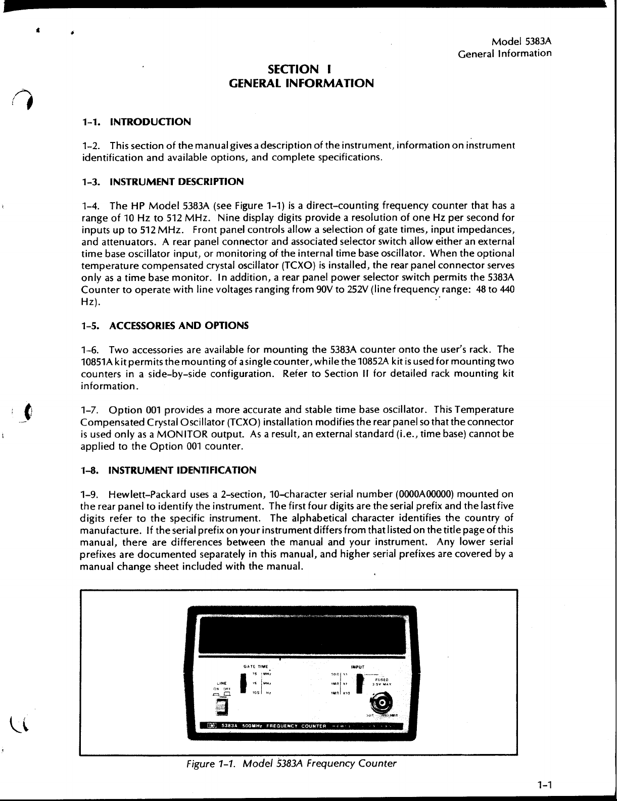
HPModel5383Α(seeFigure
base
oscillatorinput,
r
at urecompensate
as α
time
operate
Two
accesso
te
r sin
pen
sate
d tothe
T
512
512
MHz
base
monitor.Inaddition,
withline
r
ies
themountingofa
α
side-by-side con
001providesαmore
dCr
ystal
as αMONITO
option
manual
the
DESCRIPTION
MH
F
ron
.
rpan
dcr
AND
are
Oscillator(TCXO)
001
gives
options,
z
.
N
inedisplay d
tpanel
el
connectorandassociatedselectorswitchallow
ormonitoringof
ystal
oscillator(TCXO)isinstalled,
voltagesra
OPTIONS
available
single
figuratio n.Referto
accurate
R o
u tp
u
t .Asαres
co
un te
r
.
αdescriptio noftheinstrument,
and
comp
lete
specifications
1-1)isαdirect-counti
igits
co
ntrols
theinternal
αrea
nging
formounting
coun
installationmodifies
ovi
pr
α
allow
r
p
anel
f r
om
90Vto
t
h e
ter,
while
andstable
u
lt,anexte
d
e
selectionofgate
time
powe
5383Αcoun
SectionΙΙfo
timebase
rnal
n
r
esolutio
α
base
r
selectorswitc
V
252
t
h e
10852Αkit
therea
standard(i.e.,
informationon
.
g
f
r
equencycou
n
of
oneHzpersecondfo
times,
oscillator.When
r
therea
pan
h per
(line
frequency
ter
onto
theuse
isusedfo
r
d
etaile
d
oscillator.
r
p
a n
el
so
time
instrument
nte
r t
h
athas
input
imped
ances,
eit
he
r
an external
t
he op
tional
el
connectorserves
mits
the
5383
r
ange:48το440
r 's rack
r
m
oun
ting
r
ackmounting
This
Temperature
t
h
t
h
at
econnecto
base)
ca nn ot
α
r
Α
.
The
two
kit
r
be
1-8.I
NSTRUMEN
1-9
.
H
ewlett-Packa
therea
d
manufacture.If
manual,
prefixes
manualchange
r
pan
eltoi
igitsreferto
t
he
r
aredocu
e
T
IDEN
TI F
rd
u
sesα2-section,
de
n
tify
the
thespecific
these
r ialpr
are
differences
me
n te
d
separately
sheet
included
F
igure
ICATIO
instrument.T
instrument.The
efixonyo
N
urinstrumen
betweenthe
i
nth
hth
wit
1-1
e
.Model
10-characterserialnumber(
is
manual
h efir
st
fo
alphabetical
t
manual
manual,
.
Α
Fre
5383
ur
d
diffe
andyo
nd
a
quen
igits
r s f r
h
ig h
cy
are
characte
om
erse
Counte r
ΟΟΟΟΑΟΟΟΟΟ)mountedon
these
r ialpr
r
i
den
that
listedon
urinstrumen
r ial
pr
efixes
efix andthelastfive
r
of
y
this
tifies
the
t.Any
are
the count
titlepage
lowerse
coveredby
of
r ial
α
M
odel5383
General
Α
Informatio
1-10
.The printedcirc uitboards
number(e.g.,
i
den
tifiesthe
ci rcu
it-boardassembly
wit
hthe
seriesnumberonthesc h
se
r
iesnu
r
eferto
the
assembly ishigherthanthe nu
provi
dedin αman
Service
1-11
.MICRO
n
05383-60001)and
electricalch
mayhave
instrument.Therefore,whentroub
mberof
backdatinginformatio
Office
.
assembly
the
ual
changesh
FICHENUMBER
withi
n th einstru
α4-d
igitser
aracteristicsofthecom
αdifferentseriesnu
ematicdiagram
is
lowerthan
ninthis
eetwhichis
matchestheseriesnumberonth
manualforchange
mberonthesch
available
ment
areidentifiedbyα2-sectio
iesnumbe
leshootingαcircu
he
t
r
(e.g.,"SER
p
letepri
numbe
nted
mbe
rthantheassemblyor
rontheschematic d
information.Iftheser
ematicdiagram,th
f romt
he nearestHewlett-
n
,
10-digitpart
I
ES1508").Theser
-circ
uitassembly.Α
it-boardassembly,en surethatthe
e boardassembly.Ifth
iag
e c
h a
ngeinfor
ies
num
ber
r
ep
laceme
iginallysupp
raminSectionV
iesnumberon
Packard
lie
mationis
Sales
and
n
t
d
e
III,
1-12
.On
n
umber.Thisnumbermay
p
ackage
N
otes
1-13.RECOMMEN
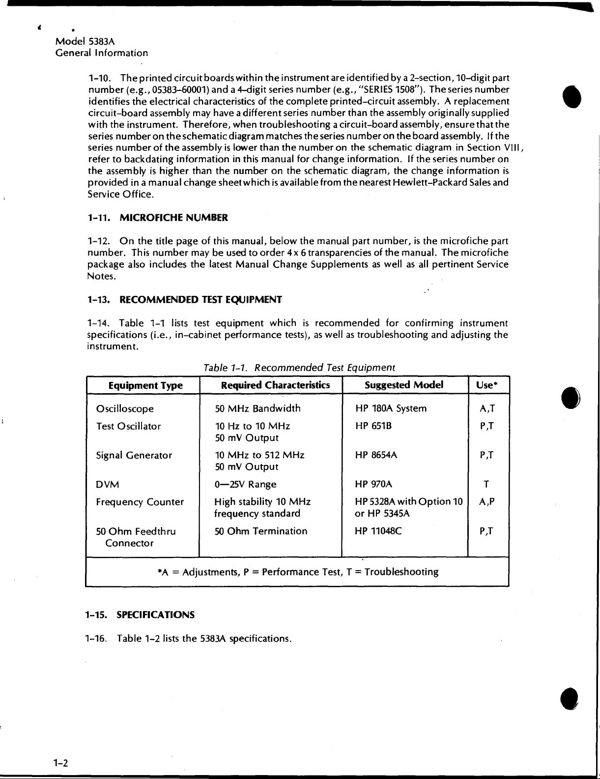
1-14.Table
specifications(i.e.,in-cabinetperforma
i
nstru
Oscillosco
Test
SignalGener
D
VM
FrequencyCounte
50Oh
Connecto
also
.
me
n
t .
ipme
Equ
Oscillato
mFeedthru
the
pe
page
title
includesthe
DEDTESTEQUIPMENT
1-1
lists
testequipmentwhichisrecomme
n
t
Type
r
r
ato
r
r
ofthisma
beusedtoorder4 χ 6transparencies ofthemanual.The
latest
Table
0-25VRange
High
frequency
50
n
ual,
ManualCh a ngeS
1-1
.
Require
50MHz Bandwidth
10Hzto10MHz
50mVOutpu
10MHz to
50mV
Output
stability10MHz
OhmTermin
belowthemanualpa
upp
nce
tests),aswellastroubleshooti
R
ecomme
dCharacteristics
512
standa
t
MH
rd
atio
nde
z
n
d
Test
r tnumber,isthemicrofic
lementsaswellasallper
ndedforconfir
Equ
ipment
Su
ggestedModel
HP
180ΑSystem
HP
651B
HP
8654A
HP
970
Α
HP
5328A
with
o
rHP5345
11048C
HP
minginstrumen
n
g
and
Option
Α
h
e
microfic
tinentSer
adju
stingth
U
se*
Α,Τ
P,T
P,T
Τ
10
A,P
Ρ
Τ
,
r
pa
he
vice
t
t
e
*
Α=Adj
1-15.SPECIFICATIONS
1-16
.Table
1-2
lists t
h e
ustments,Ρ=Performance
5383
Αspecifications
.
Test,Τ=Tr
oubleshooting
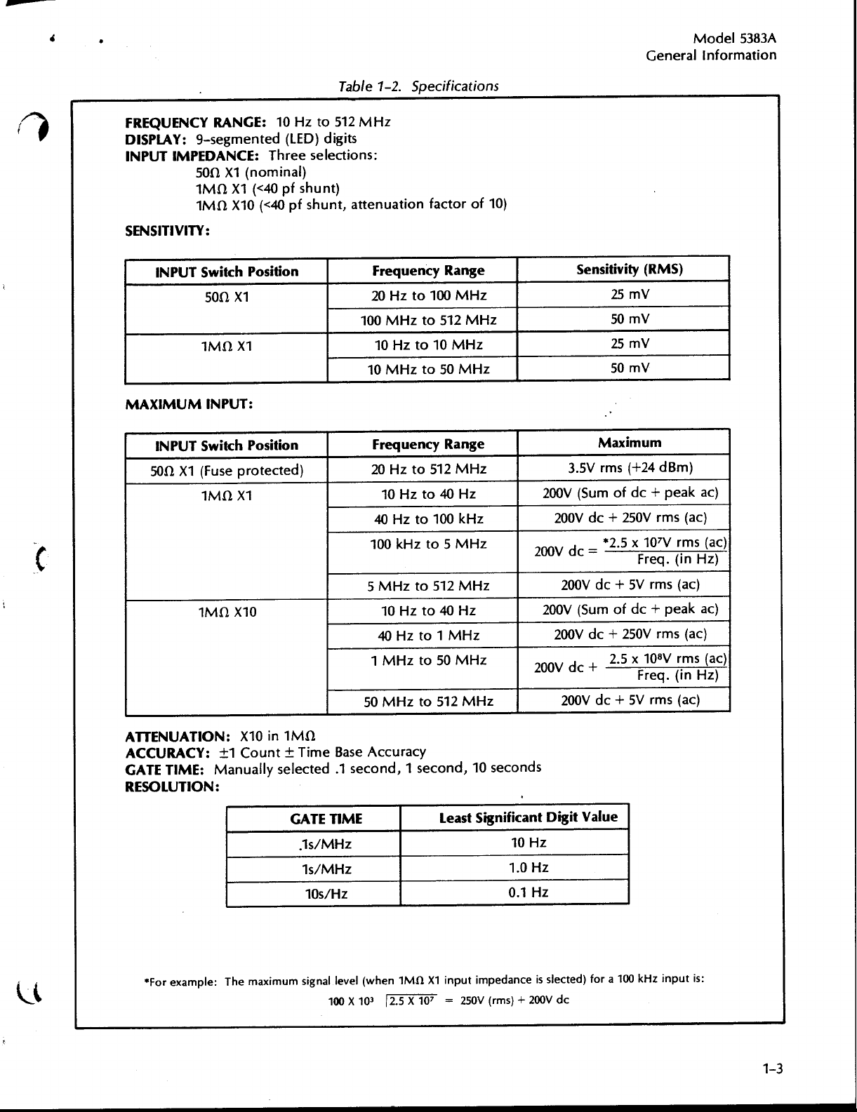
Table
1-2.S
p
ecifications
Gener al
Model5383
Informatio
Α
n
FREQUEN
CYRA
DISPLAY:
I
NPUTI
MPE
SENSITIVITY
I
NPU
T
MUM
M
AXI
I
NPUTSwitc
50ΩΧ1(Fuse pr
E:10Hzto
NG
9-segmente
NCE:Threeselections
DA
ΩΧ1(n
50
1
ΜΩΧ1
1
ΜΩΧ10
d(LED)digits
ominal)
(<40pfs
f shunt, attenuation factorof
(<40
p
:
Switc
h P
ositio
n
ΩΧ1
50
1
ΜΩΧ1
I
NPUT:
ositio
otecte
n
d
)
h P
ΜΩ
1
Χ
1
hun
512
t)
MH
z
:
en
Frequ
20
100
cyRange
Hzto100
MHz
to
10Hzto10MHz
MHz
to
10
FrequencyRa
20Hzto
to
10
Hz
to
40
Hz
100kHzto5
MHz
512
MHz
50
MHz
nge
512
MHz
40Hz
100kHz
MH
z
10)
Sensitivity
25
50
25mV
50
M
aximum
3.SVrms
200V(S
200
200V
do
ofdo+
um
Vdo+250Vrms(ac)
.5
*2
(RM
S)
mV
mV
mV
(+24dBm)
peakαι
χ107Vr
(i
Freq
.
)
ms=(ac)
nHz)
Χ
ΜΩ
10
ATT
1
ENU
ATION:Χ10in1ΜΩ
ACCURACY:±1Count±
GATETIME:Manually
RESOLU
TION:
*
For
example:Themaximum
selected.1
TimeBase
GATE
TIME
.1s/MHz
1s/MHz
10s/Hz
signal
level
100
5
MHz
to
512
MHz
to40Hz
10
Hz
40Hzto1MHz
1
MHzto 50
50
MHz
to
512
MHz
MH
z
Accuracy
second,1seco
nd,10 seconds
L
east
Significant
(w hen1ΜΩΧ1inputimpe dance
Χ 10
32.5
Χ 10
7=250
V(rms)+
200Vdo+
200V(Sum
Vdo+250Vrms(ac)
200
200
+
Vdo
Vdo+5Vrms(ac)
200
DigitValue
10
Hz
1.0Hz
0.1Hz
slected)forα100kHzinpu
is
200Vd o
SVrms(ac)
do
+
of
2.5χ108
Freq.
pea
Vrms
(in
k ac)
(ac)
Hz)
t is :
t
M
Ge
o
ι
del5383
ner al
I
Α
nfor
mation
TI
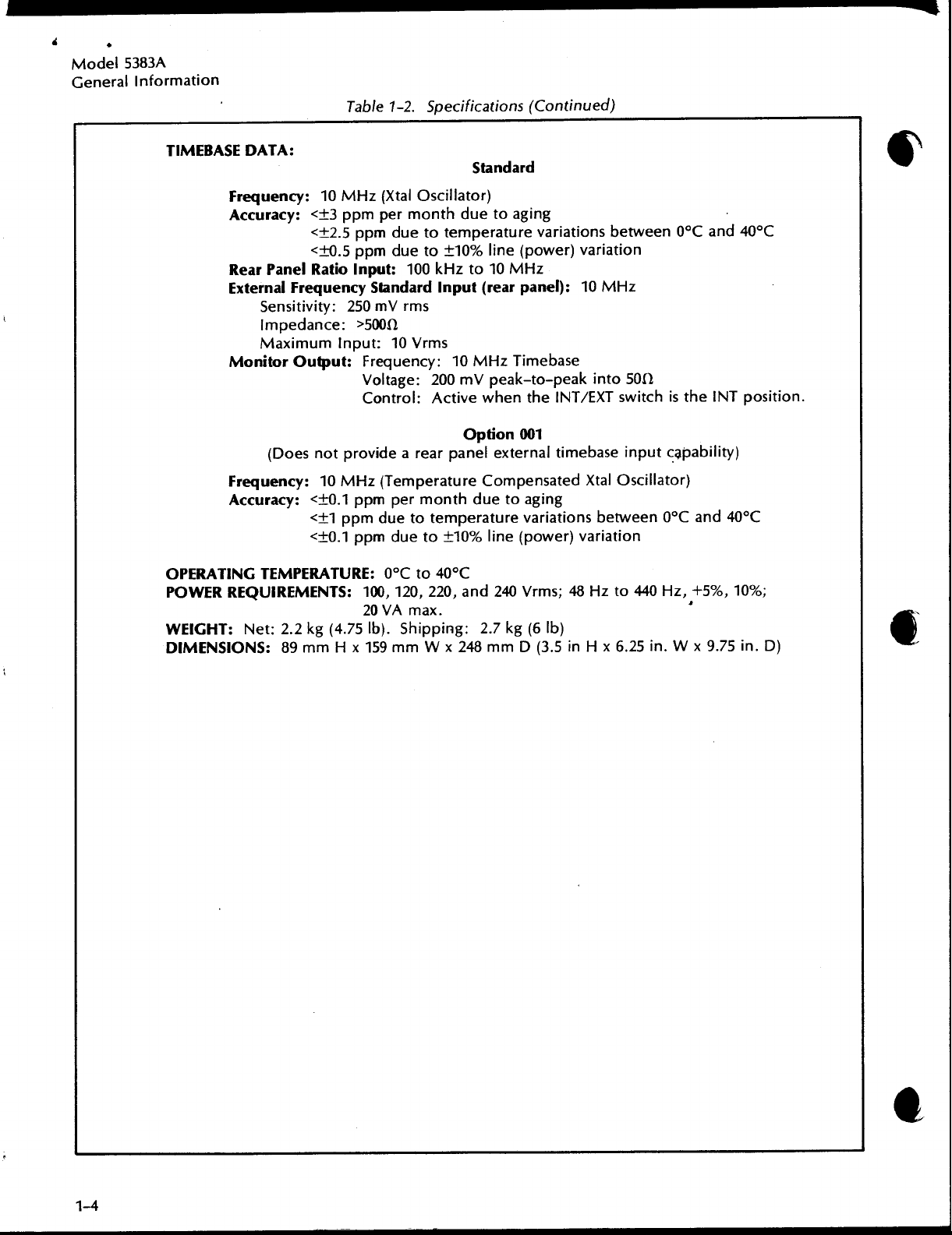
MEBASE
Table
DATA
:
Frequ
Accuracy:<±3
Rea
E
Monitor
Frequ
Acc
ncy:10MHz(Xtal
e
ppm
permont
<±2.5ppmdueto
<+0.5pp
rPanelR
xternalFrequency
Sensitivity:250mVrms
Impedance:>500
M
(Does
ency:10
uracy:<±0.1ppmpermont
atio
aximumInpu
Output:Fr equency:10
not provide αrearpanelexternal
<±1
<±0
mdueto±10%
Input:
Standa
t :10Vr
V
oltage:200mV
Control:Active
MHz
(Temperature
p
pmduetotemperat ur
.1
pp
m
1-2.Specifications
Standa
Oscillator)
h duetoagi
temperaturevar
line(p
100kHzto10
npu
rd
I
Ω
ms
dueto±10%
h
t(r
ea
ΜΝτ
pea
whenthe
O
p
tion001
Compen
due
line(p
MHz
rpanel):10
Timebase
k-to-pea
to
e va
(Continued)
rd
n
g
iationsbetween0°Cand 40°C
ower)var
ΙΝΤ/ΕΧΤ
timeb
satedXtal
aging
iations
r
r)variation
owe
kinto50
n
iatio
MHz
Ω
switchisthe ΙΝΤ
i
npu
ase
between0°Cand
tc4p
Oscillator)
ability)
40°C
position
.
O
PER
ATI
NGTEMPE
WER
PO
WEIGHT:Net:2.2kg(4
DIMENSIONS
REQU
RATURE:0°Cto40°C
I
REMEN
:
89mm
TS:100,
20 VAmax
.75
Ηχ
159mm
lb).S
120,
220,and
.
h
ipping:2
Wχ248mmD(3
240Vrms;48
.7kg(6
lb)
.5inΗχ6.25in.Wχ 9
Hz
to
440Ητ,
+5%,
'
10%
;
.75in.D)
ι
S
E
CTIO
N
11
2-1
. INTRODUCTIO
2-2
.This
s
hippingthe frequency counte
2-3
.
2-4
.
instrument isunpacked
switches,
andthenearestHewlett-Packard
p
r
oceduresare
manual.R
Salesand
waitingforth e
2-5.STORAGE
sectionof
UNP
ACKINGAN
If the
hipping
s
etc.If theinstrument
etain
Service
N
themanu
D
cartonisdamaged,
locate
din
shipping
the
Office
claimagainst thecarriertobe
AND
SHI
alpr
I
NSPECTIO
. Inspecttheinstrumentfordamagesuchas scratches,dents,brok
SectionV,
carton
willarr
PMEN
INSTALLATIO
ovi
desi
nfor
r
.
N
as kthatthe carrie r'sagentbe presentwhenthe
isdamage
Salesand
angefortherep
T
d orfailstomeet
nd
Salesand
a
andth
e paddingmaterialforthecarr ier'sinsp
mationabout
Service
settled.
N
Office
Service
ai ror rep
unpacking,i
performance
immediately
Officesareliste
lacementoftheinstrumentwithout
n
ecting,
s
p
tests,notifythecarrier
.Performancechec
t
h
d
at
e
M
odel
sto
r ing,and
backofth
ection.Th
5383
I
n
stallation
en
k
is
e
Α
2-6
.PACK
always
canprovi
pack
agi n g
2-7
.ENVIR
follows
α
b
ε
2-8.LINEVOL
2-9
.The counteriss
120-volt.If
follows
α
b
AGING.
usethe b
de pack agi n
companiesinmany
ONMENT.Cond
:
.
M
aximum
M
i
.
nimu
.
M
aximumtemperature:+167°F(+75°C)
any
:
.
U
singα
S
ELE
CTORswitches
d
esiredvoltage
.
En
surethatt
100-voltor
240-volt
p
To
est
pack
aging
gmaterialsuchasthatusedfo
altitude
tempe
m
TAGESELE
othe
smallscrewdr
operation
r
atu
CTIO
upp
lie
r
supp
ma
he correct
120-volt
r
otect
val
uableelectronicequipmentduringstorageorsh
methods
citiescan pr
itions
:
25,000
re:
N
dfr
omthefactory
ly
voltageisto
iver,αpencil,orothe
on
rkingont
fuseisinstalled
operatio
.
available.YourH
ovi
de d
duringstorageandshipmen
ft
.
-40°F(-40°C)
the counter'srearpanelto
herea
n orα L
.
withth
beused,changetherear-panel
r
pan
.Use
isted,0.125ampere,slow-blowfu
ewlett-
ror
ependablecu
.
e
LI
NEVO
rsuitable tool, setth
.
el
L
isted,0.250ampe
α
PackardSales
iginal
stom
t s
L
TAG
the p
factorypac
pack
agingonsho
houldnor
ESELE
CTO
ositions
re,
ipment,
and
Service
k aging.
mallybelimitedas
R
switc
switchsetti
e LINEVOLTAG
h
own
s
slow-blowfusefo r
se for220-voltor
Contract
r tnotice
h
es
n
exttot
Office
set
fo
ngsas
he
.
r
E
M
odel
n
stallatio
I
5383
n
Α
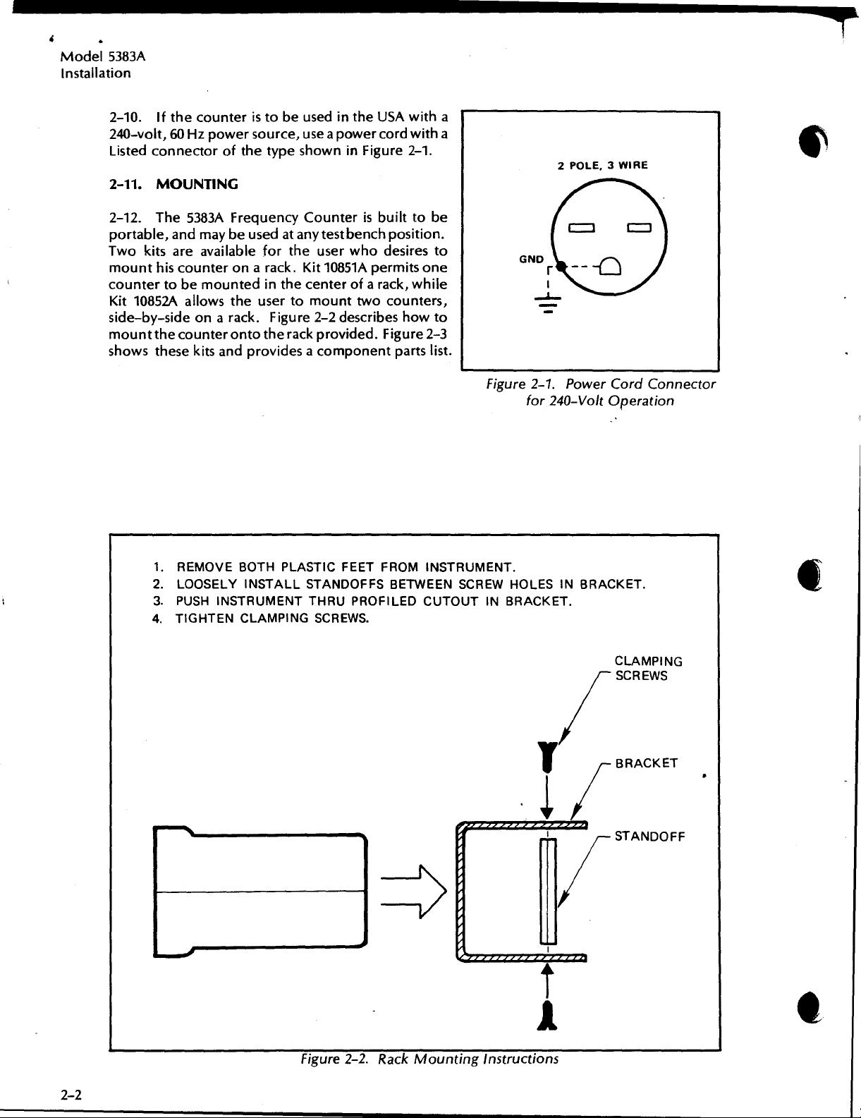
2-10
.If the counte
240-volt,
L iste
2-11
2-12.The
p
o
Two
m
ounthis
counte rtobemou
K
it
side-by-sideonαrack.Fig
mountthecou
showsth
60Hzpowerso
dcon
necto
.MOUNTI
5383ΑFrequ
r
table,and
kits
are
counteron
10852Αallowstheusertomounttwo
esekitsandprovidesαcom
r is
rofthetypesh
NG
may
beuse
availablefortheuserwhodesires to
nte
nte
rontotherackpr
eusedinthe
to
b
ur
ce,use
owninFigure
encyCou
d
at
any
αrack
.Kit
dinthe centerof
ure 2-2 d
U
withα
SA
αpowercord
nterisbu
test
ben
10851Αpermitson e
escribeshow
ovi
ded
ponentparts
wit
2-1
ilttobe
chposition
α rac k
,wh
counters,
.Figure
hα
.
ile
2-3
list
to
.
.
F
igure
2-1
.PowerCordCo
V
for240-
olt
O
peratio
nnecto
n
r
1.REMOVE
2
.LOOSELYIN
3.PUSH INST
TIGHTENCLAMPINGSCREWS.
4
.
L
.-O
f
BOTH
PL
ASTIC
STALLSTANDOFFS
RUMEN
TT
FEETFROMINSTRUMENT.
HRU
PROF
BETWEEN
ILED CUTOU
SC
REW
HOLES INBRACKET
T
BR
ACKET
IN
.
.
F
igure
2-2
.
R
ackMoun
ting
Instructions
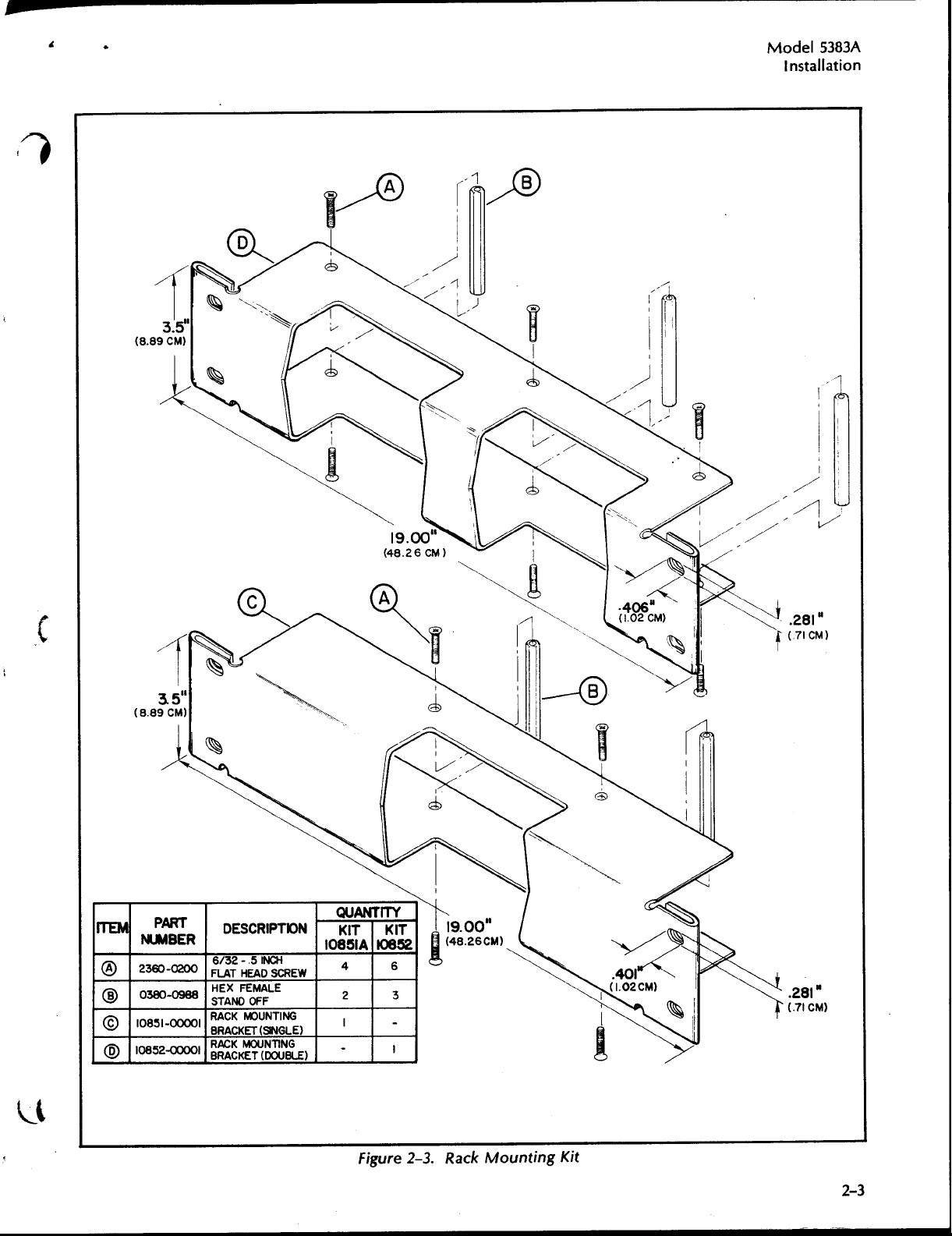
M
odel
5383
Installation
Α
Ο
ΟΘ
©
Ορ
Α
PART
NUMBER
2360-0200
0380-0988
Ι
085Ι-00001
10852-00001
DESC
RIP
6/32-
.51NC
H
EADSCREW
FLAT
HEX
FEMALE
STAND
O
FF
RACK
MOUN
BRACKET(SINGLE)
BR
AG
DO
TIO
H
TING
UBLE)
N
10851Α0852
Q
UANTITY
KIT
4
2
Ι
-
KIT
figure
6
3
-
Ι
k
2-3
.
R
ac
ountingKit
M
2-3
M
odel
5383
Α
Operatio
n
I
N
3-1,
.Th
3-2
techniques,
ment
.
CO
3-3
igures
.
F
3-4
va
rio
the
guidelines
M
3-5
3-6
m
Pr
surements
input
degr
andselectionof
surements.Table
the
EAS
.
.
N
oise
.Using
ents
operselectionof
impedance,
ade
r
u se
UCTIO
TR
OD
is
section
N
TR
OLS,
3-1
u
s
connecto
dbr
an
UREMEN
r
idingon
the
.
Wh
e
the capab
o
b
tai
n
m
N
containsdescriptionsoft
r
a
nd ope
NNE
CO
a
nd 3-2
r
s
ief
operatormain
T
TECHNIQUES
the
internalΧ10
the
nthe
r
eisαdifference
r
ingingmay
ilityofthecounter.
compatible
3-1
(page
u
m
axim
rcheck
ato
CTORSAND
d
esc
and
i
nd
input
i
npu
imp
t
appea
5383
3-2)provides
u
se of
s
.
ribeth
e o
icato
r s
te
na
signal
attenuator,
edance
r
Α
i
npu
f
r
the
equency
SECTIO
O
PER
INDICATORS
.
ncepr
canca useerroneous
betweent
on
Kn
t
N
III
ATIO
N
he con
erationof
p
The
also
t
h
owledgeoft
impeda n
some
trols,
following p
oce
dur
es
orexternal
allows forstable
h
sig
e
sig
n
e
al.T
ces
suggestedmeasurement
counte
connectors a n
the
for
attenuato
n
al
hisrin
h
e
and
r
.
Α
5383
cont r
aragraphs
the
f r
equencycoun
o
r
un
andaccurate
source
gi n g
sig
n
so
al
atte n
uationpermits
d
ols
alsoprovi
stable
r smin
i
mpedan
uldinter
co
ur
ce
i
nd
icators,
ndth
a
ter.
f
r
uency
eq
imizes
f r
equ
nd
ce a
fere
ci
rcu
it
techniques
measure-
f
e
un
ctionof
de op
measure-
thisproblem
ency
t
h
e
with,
characteristics
proper
erati
mea-
counte
a
nd
mea-
tohelp
ng
.
r
.R
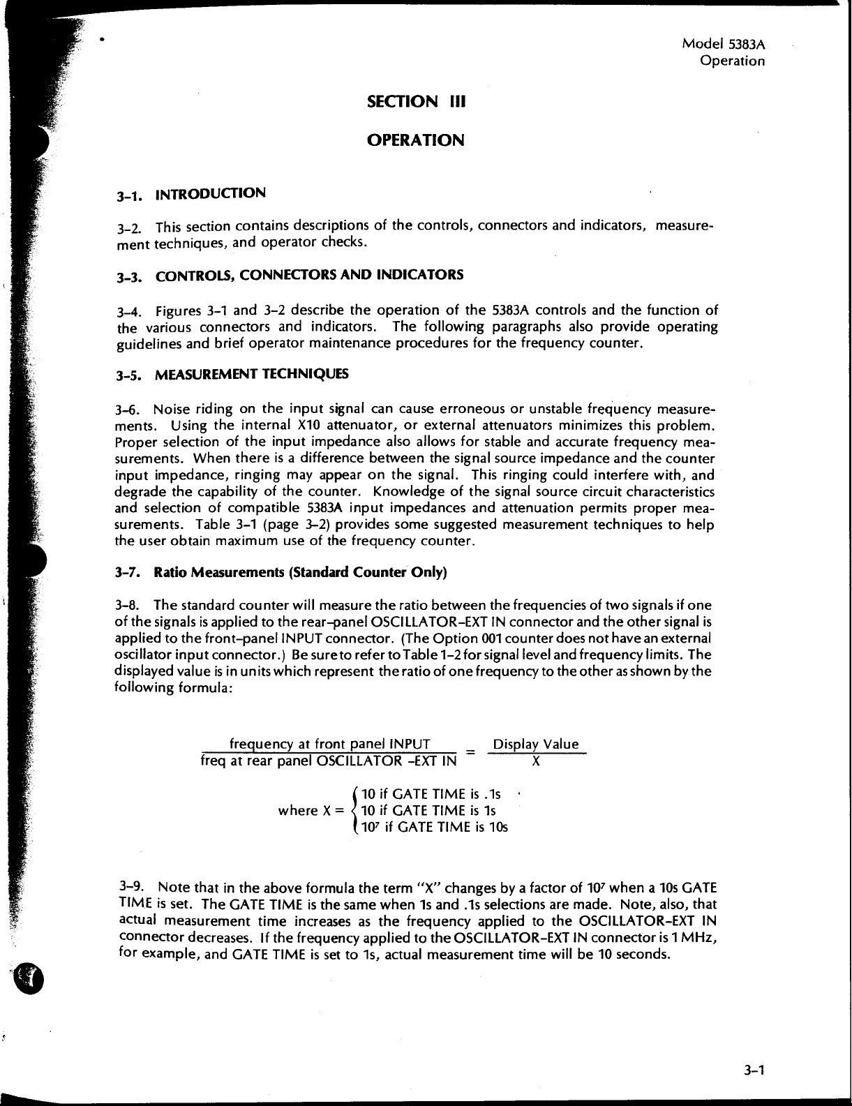
3-7
3-8
of
app
oscillato
disp
followi
3-9
TIME
act
co
fo
atioMeasu
.Thestandardcoun
thesig nalsisappliedto
lie
d
layedval ueis
ngformu
.
N
is
u
al
nn
ecto
r
example,
f
to
the
ront-
rinpu
t
nn
co
i
n un
la
:
f
freqatrea
ote
that
in
set.The
measurement
r
GATETIME
dec
r
eases.1f the
andGATETIMEissetto1s,
r
ements
p
anel
ector.)
its
r
equ
encyatf r
r
the
above
time
(Sta
nda
rdCounter
terwill
t
whic
measure
he
rear
-panel
I
NPU
T connector.
B
e
suretorefe
h
r
e
pr
ont p
p
a nelOSCILLATOR-
where Χ
formula
is t
h
increasesast
f r
equencyappliedto
t
OSCILLATOR-
esen
t theratioofone
anel
10ifGATETIMEisAs
=10ifGATETIMEisis
J 10
7ifGATETIMEis10s
thete
e
same
Only)
he
r
atio
betweenthef r
(TheOption001
r
to
Ta
1-2
b
le
I
NPU
T
ΕΧΤ
IN
m
"
r
Χ
" changes
w
he
n 1s a
nd
h efrequ
actual
ency
the
measurement
equenciesoftwo
ΕΧΤINconnectorandtheot
counterdoesnothavean
r
sig
n
level
a
fo
__
OSCILLATOR-
al
frequencytotheot
Display
by
1s
selections
app
liedto
time
ndfr
equ
he
V
ue
al
Χ
α
factorof107
are
made.Note,
theOSCILLATOR-
ΕΧΤINconnecto
will
be 10 seconds.
signalsifo
ency
r
as s h
w
hen α
he
r
signal
external
limits.The
ownbyt
10s
GAT
also,
ΕΧΤ
r is 1
MHz,
ne
is
he
E
that
IN
M
odel
Operatio
5383
n
Α
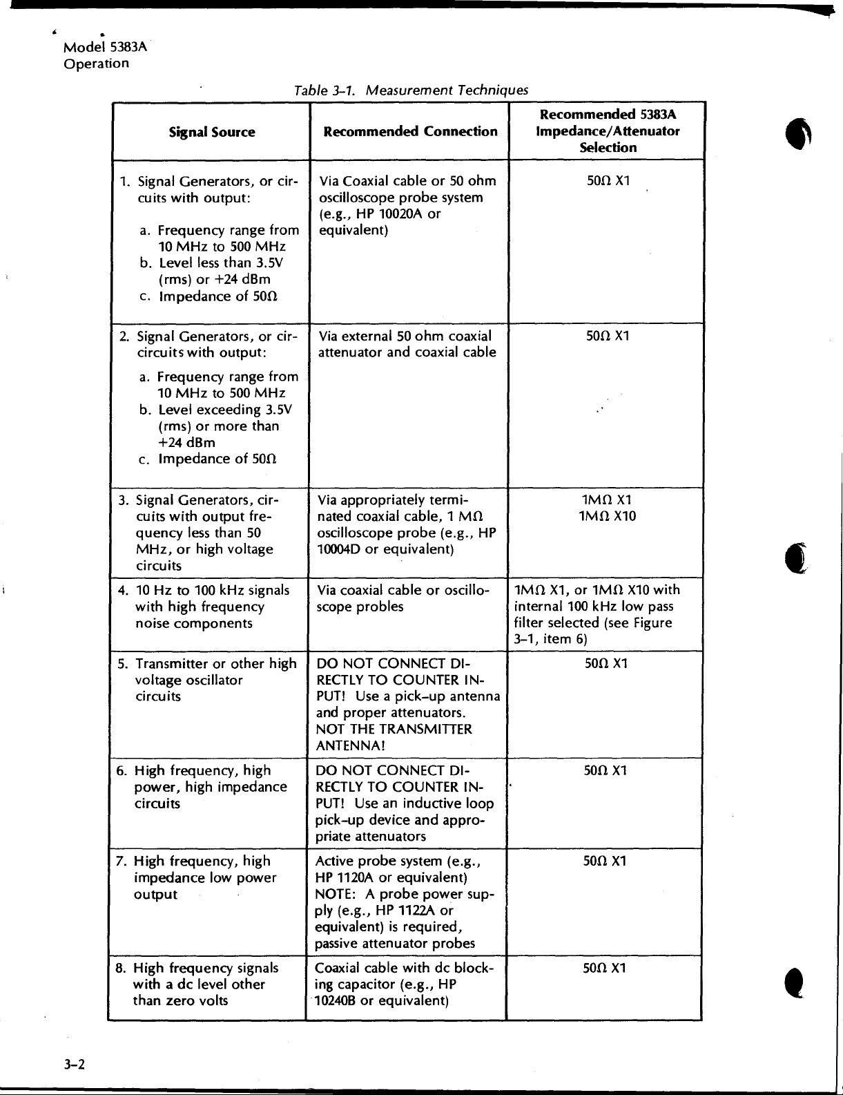
Table
3-1
Signal
Source
.Measurement
R
ecomme
nded
Techniques
Connectio
R
ecomme
n
Impedance/Attenuato
nded5383
Selectio
Α
r
n
1.SignalGener
cuits
withoutput:
α.Frequencyra ngef rom
10
MHzto
b
.Level
ε
.
2.SignalGenerators,orcir
circuits
α.Frequencyrange
b
.Level
c
.
3.SignalGen erato
cu
itswit
q
uency
MHz,o
circuits
4.10Hz
withhighfr
noise
5.Transmitte
voltage
circuits
less
(
r
or+24dBm
ms)
Impe
dance
wit
h output
10
MHz
to
exceeding 3
(rms)ormoreth
+24
dB
m
Im
pedan
ceof50
h outputfre-
lessthan50
rhighvoltage
to
100kHz
e
components
r
o
oscillato
orcir-Via
ato
r s,
500
MH
z
t
han3.5V
of 50
Ω
:
f r
om
500
MH
z
.5
a n
Ω
r s,cir -
signals
ency scope probles
qu
roth
high
e
r
r
Coaxial
oscilloscopeprobe
(e.g.,HP10020Αor
equivale n
-
V
ia
attenuatorandcoaxial
V
V
iaappropr
n
atedcoaxial
oscillosco
10004Dorequ
V
ia
DO
RE
CTLY
PU
T!Useαpick-upantenna
a
nd properatte
NOT
ANTENNA!
t)
external
pe probe(e .g.,HP
coaxialcab
NOT
CO
TO
ΤΗΕTRANSMITT
cableor50oh
system
ohm
ivalent)
leor
oscillo- 1
CT
UN
T
ER
nuators
coaxial
cable
DI-
IN-
.
ER
50
iately termi-
cable,1ΜΩ
NNE
CO
m
ΜΩΧ1,or 1
inte rnal100kHz
filterselected(seeFigure
3-1,
item
50ΩΧ
50ΩΧ
1
ΜΩΧ1
1
ΜΩΧ10
ΜΩΧ10
6)
50ΩΧ
1
1
wit
lowpass
1
h
6
.Hig h
7
.Hig
8
.Highfrequency
frequency,hig
p
owe
r ,hig
circuits
h freque
im
pedan
outpu
t
withαdo
t
han zero
ce low
levelother ing
volts
himp
n cy, high
powe
signals
h
edance
DONOT
RECTLYTO
T!
PU
pick-updeviceandappr
pr
iate
Activeprobe
r
HP
NOTE:Αpr
ply (e .g.,HP
eq
uivalent)
passive
Coaxial
10240
CO
NNE
CT
CO
UN
TER
U
se
anindu
attenuators
1120
Αorequ
atte
nuatorpr
cable
capacitor(e.g.,HP
Β oreq
ctive
system(e.g
ivalent)
obepowersup-
1122Αor
isrequire
wit
hdoblock-
uivalent)
DI-
d,
obes
IN-
loop
o-
.,
50ΩΧ
50ΩΧ
50ΩΧ
1
1
1
ΙΙΙΙ
ΙΙΙΙ
M
3-10.OPERATO
3-11
.Th
esequickpr
failure
is suspecte
RCHE
d
:
CKS
elimi
n a ry c
hecks shoul
d beper
fo rmed by
del5383
o
O
peratio
t
heoperatorwhenaninstrument
Α
n
Pr
mΙ.
oble
CHECK
α
.
Equ
b
.Prope
ι.Rearp
N
umber
2110-0318)
Pr
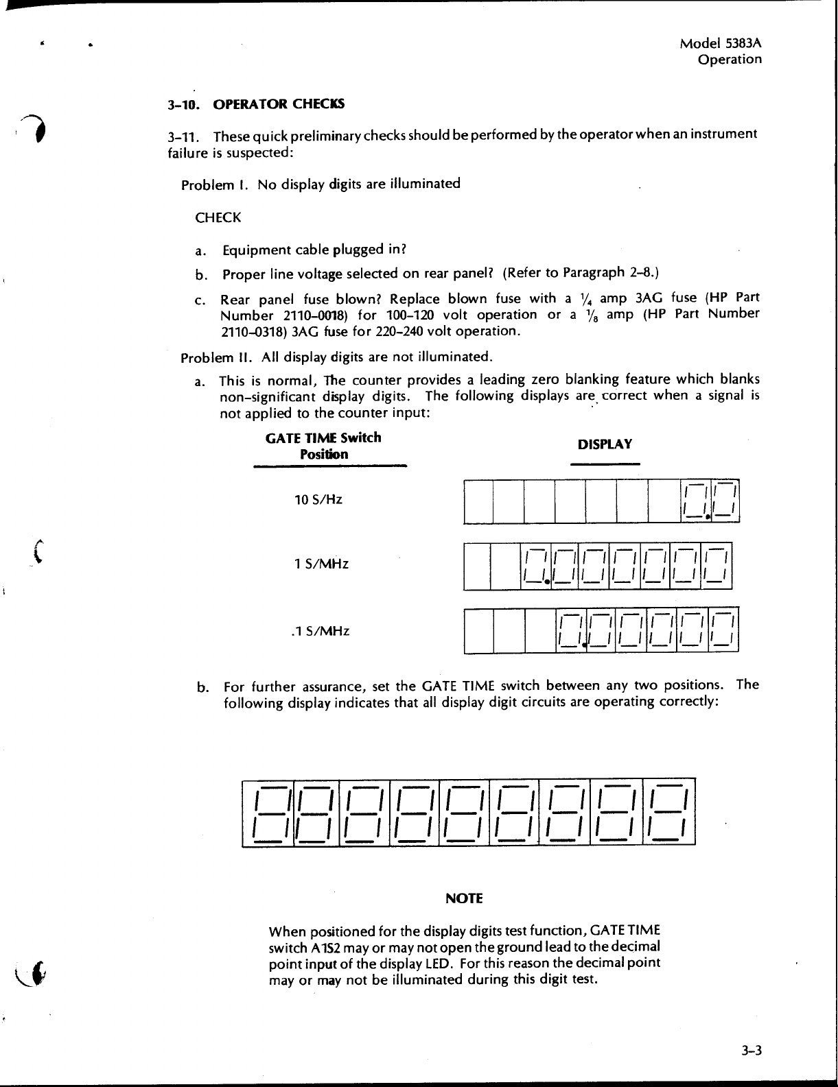
ob lemΙΙ.
hisisnormal, Thecoun
α
.
T
non-significant
n
ot
Νοdisplaydigits
ipmentcab
li
r
a nelfuse
Alldisplaydigits
appliedto
GATETIME
le
nevoltage
2110-0018)
fusefor
3AG
d
isplaydigits.Thefollowingdisplays are
the
Position
H
10
S/
1S/ΜΗτ
illuminate
are
lugge
p
din?
selectedonrearpanel?
blown?Replace
for100-120
220-240
are not
rprovides
te
cou
n terinput
Switc
h
z
d
blow
voltoperationor
volt
operatio
illumi
n
:
R
efertoParagraph
(
nfusewithα /4amp
α
n
.
d
.
ate
α leadi
ng zeroblan kingfeature
DISPL
ΙΙΙΙΙΙΊ
ΙΙ,ΙΙ Ι-Ι
2-8
.)
fuse
3AG
amp(HP
correctwhen
AY
ΙΙ
Ι Ι-ΙΙ_
Ι
(HP Part
P a
r t
Number
whichblanks
α signal
Ι
Ι Ι-Ι
is
b
.Forfurther
followingdisplayind
I
it
ι
ίι
Whe
switc
p
oint
mayormaynot
.1S/ΜΗτ
assurance,
II-
ι1
ίι
n
positione
h
AlS2
inputoft
set
the
icates
that
ίι
dfor
mayor
maynotopentheground
h edisplayLED
ill
be
TIME
GAT
E
alldisplaydigit
ι
ι
-
ΝΟΤΕ
th
edisplay
.
uminated duringthisdigit
switchbetweenany twopositio
ci r
cuitsareoperati
Ι
Ι
Ι Ι
test
function,
digits
r thisreasonthe d
Fo
ι
_
ι
_
lea
ΙΙΙΙΊ
ΙΙ
Ι
-
dtot
ι
ιι
GAT
ecimal
test
ΙΙ
ι
_
he d
.
ΙΙ
-ΙΙ-ΙΙ-Ιι-
n
gcorr
ectly
ι
ι
E
TIME
ecimal
point
Ι
ι
ns.Th
:
e
d
el
5383
n
Α
Pr
oblem
CHEC
α
b
Ill
K
.Is t
coun
.
Does
Χ
1
covers
wit
2110-0436)
.
T
he
:
h
r
ear
e
teronly
thisproblem
p ositio
hsp
n
to gain
are
f r
equ
ency
co
panelΙΝΤ/
.)
?
This
accesstothis fuse
provi
.
ΕΧΤ
occuronly
i
nd
icates
ded
on
t
he
ter
isnot
un
switc
hinthe
w
h
enthe
that
t
heintern
(refertoParagraph5-17,noteWARNI
M
ain
Boa
untin
co
ΙΝΤ
position?
f
r
ontpanel
al
rd
Assembly.Or
ΝΟΤΕ
g
the
fuse,
input
(This
I
NPU
A1F1,
de
signal
.
switchexists
T
switchis
blown.Remove
is
i
ranotherfu
inthe
nthe
ΩΧ1
50
i
NG)
.
R
ep
se
(HPPartNumbe
standa
o
nstr
lace
rd
r
1
ΜΩ
ument
fuse
r
M
o
Operatio
ι
.Does
p
ositions
(refertoParagraph
switc
3-12
.Finally,
operationoft
α
.Set
b
.Set
ε
.Connectαcoaxial
d
.
-
e
.
hein
t
h
p
osition.
thef r
I
NPU
Tjack.
10
MHz
-
no
r
mally
Fo
r
loop-around
connector(see
REMEMBER
(RMS)
Χ
1!
thisproblem
a
ndth
h toth
thisquickand convenient
str
rearpanel
e
ont
d
isplay
.
TO
OR+24
e
left(i.e.,away
m
u
panelI
e
i
n
t
:
e
ΙΝΤ
ca
(±1
checkof
Table
D
occur
npu
5-17,
NPU
lebetween
b
least-significantdigit)
5-1,
KEEP
ΤΗΕ
BM
WHEN
οηΙ;-when
t
f r
equency
note
f romthe">")
/ΕΧΤ
switch(existsonthestandardcoun
T
switchto
the1
2
test
I
NPU
T SIGNA
ΤΗΕ
I
NPU
T
SWITCHISINΤΗΕ50Ω
I
the
NPU
higher t
goes
theWA
loop-around
therea
ΜΩΧ1,
items
RNING)
.
the50ΩΧ1position
r
pan
el
indicates
o
r
Χ10
f,g.)
e,
.
L
LEVEL
T
switchis
h
a n
100kHz?Remove
Set
.
c
heck
is
.
OSCILLATO
t
hatth
I
NPUT
BELOW
the board-mounte
p
3
i
nthe
provi
ded
teronly)tothe
R
jackandth e
e coun
at h
s,use α
.5
V
1
ΜΩΧ1
to
verifynormal
te
r is
500Fee
o
r
thecove
d
FILTER
f r
ontpanel
operati
dthru
Χ
10
INT
ng
r s
3-13
r
eferto
.If,
the
afte
r t
h
ese
operato
Troubleshooting
rcheck
h
arts
C
s are
:Figure
performed,
5-1
and5-2inSectio
t
h e
coun
te
r
d
n
Vforfau
oesnot
operate
lt
analysis
normally,
proce
dur
es
.
5383
eratio
Α
n
M
od
el
O
p
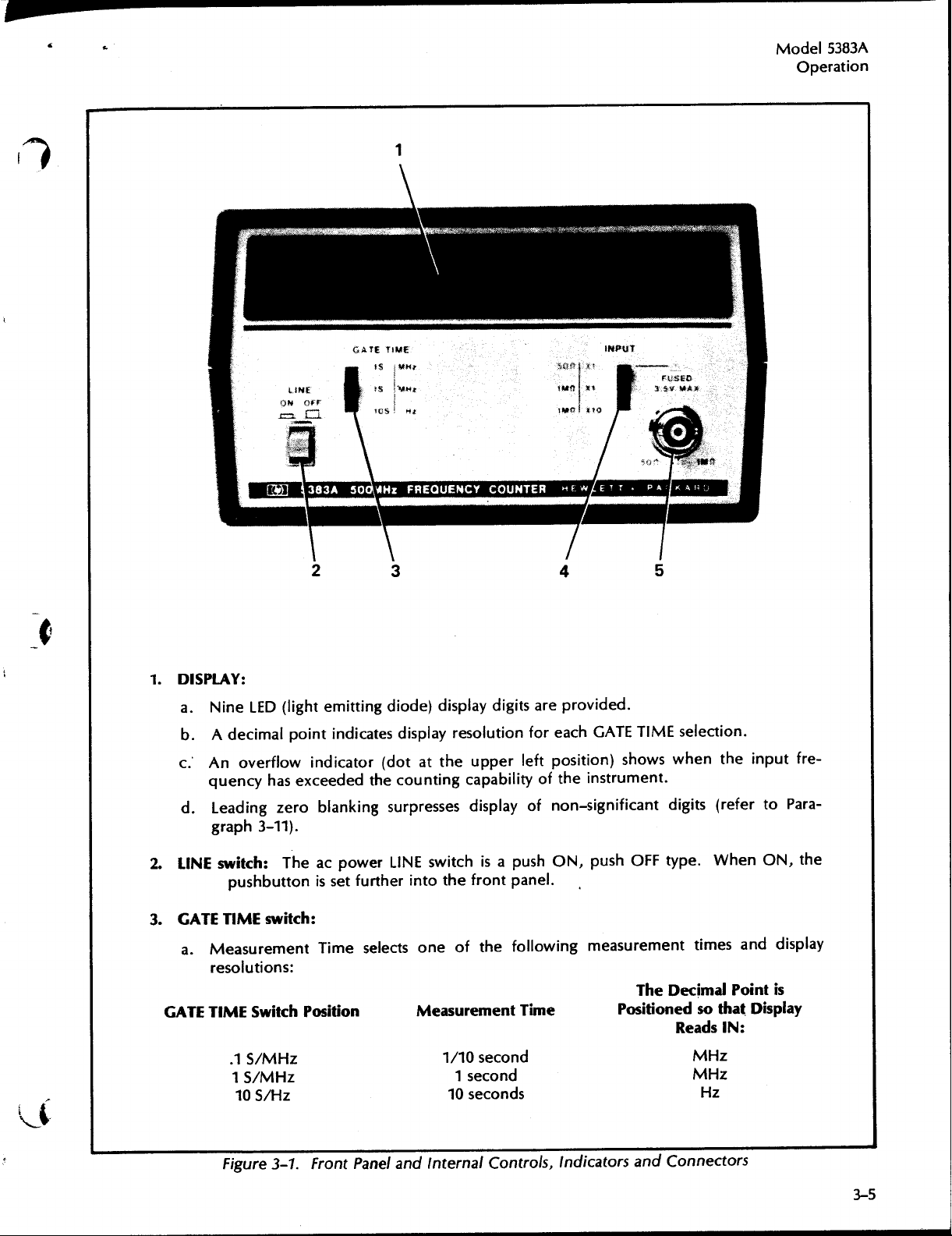
1.DISPLAY:
i
n
α
.
N
e
b
.
Αdecimalpoi n tind
c.'An
quencyhas
d
.
Lead
graph3-11)
2.LINE
switch:
pushbu
3
.
GATETIME
α
.Measureme
r
esolutio
GATETIME
.1S/ΜΗτ
1
10S/Ητ
D
(light
LE
emittingdiode)displaydigits
icates
overflowind
icator(dotatthe
excee
ded
the
ingzeroblankingsu
.
h
T
tto
powerLINE
e
ac
nissetfurth e
switch:
ntTime
selects
ns:
Switc
h P
ositio
n
5/MHz
r
e provi
a
d
isplayresolutionfor
upper
leftpositio
countingcapabilityoft
r
essesdisplay
rp
switchisαpu
r
intothe
one
of
M
easur
1/10 seco
1
10
f ron
the
ement
seco
seco
of
shON,
tpanel
followi
Time
nd
nd
nd
s
.
ded
.
each
GATETIME
selection.
n)showswhen
he
instrument
.
non-significantdigits(r
p
u
s hOFFtype.Wh
measurement
ng
The
times
Decimal
Positionedsothat
R
eadsIN
MHz
MHz
Hz
h
t
einpu
t f r
efertoPara-
enON,
nddisplay
a
Point
is
Display
:
e-
t
h
e
n
r
F
ig
ur
.
Front
Pan
el a
nd
inte
e
3-1
rnalCon
ols,Ind
t
icators
a
nd
Co
nectors
3-5
α
M
del5383
o
O
peration
Α
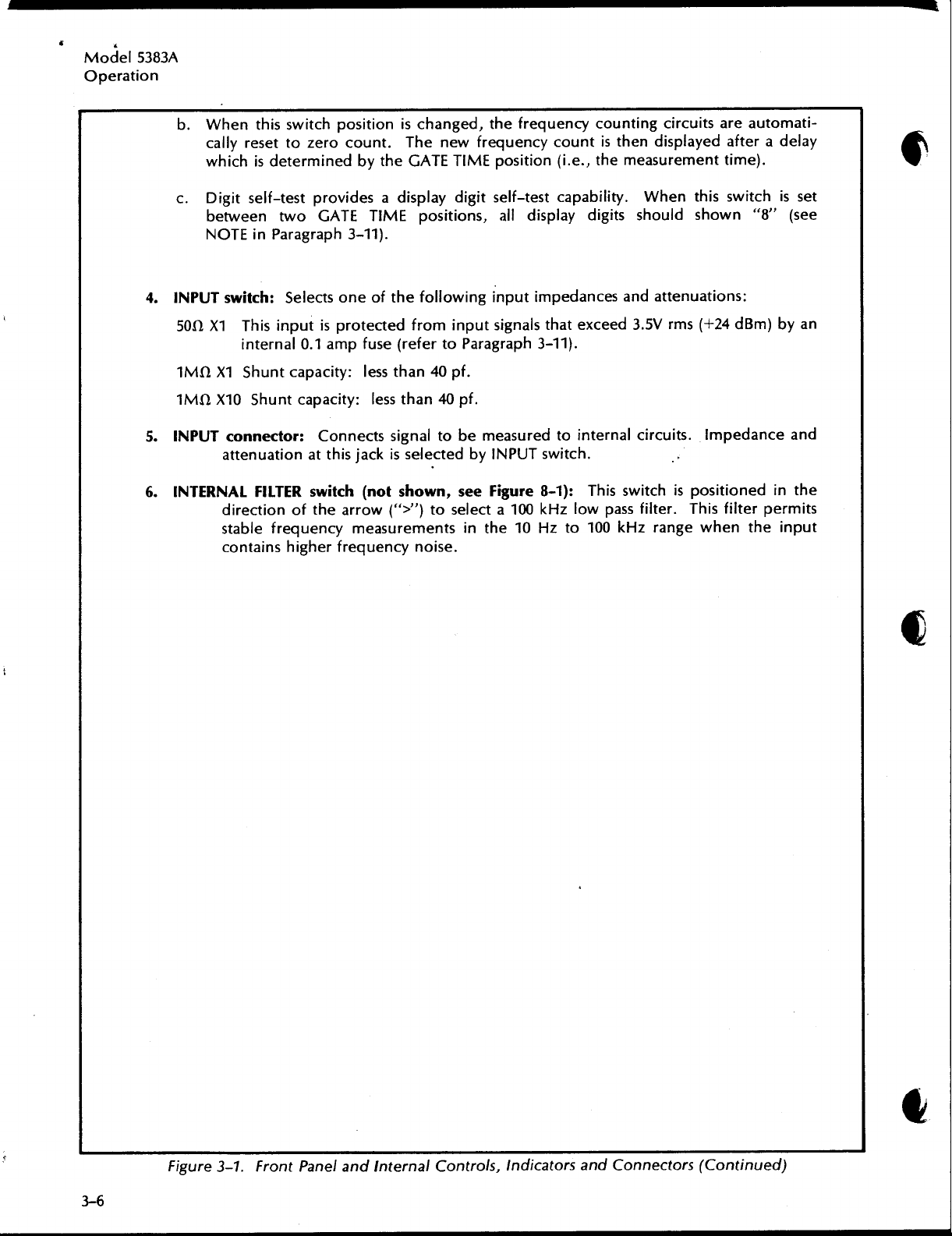
b
.
Wh
callyreset to zerocou nt.T
whichisdeterminedbythe
Digit
ι
.
b
etweentwo
NOTEinPar
4
.I
NPUTswitch:
50ΩΧ
1
1
ΜΩΧ1Shuntcap
1
ΜΩΧ10 S
e nthisswitc
h p
ositionischan
h enewfrequ
GATETIME
self-test provides
GATETIME
agra
ph
Selects
T
hisinputispr
αdisplaydigit
positions,
3-11)
.
oneofthefollowinginputim
otecte
dfrominputsignals
inte rnal0.1ampfuse(refertoPar
acity:less
than40
huntcapacity:lessthan40 pf
ged,t
he frequency counti
ency
osition(i.e.,the
p
self-test
alldisplay
t
ph
3-11)
pf
agra
.
.
n
countis thend
measurement
ility
capab
ped
h at
excee
.
d
igitssh
ancesand
d 3.5Vrms
.
gcircu
itsareautomati-
isplayedafterα d
time)
nthisswitchis
Wh
e
oul
d shown
attenuatio
n s
(+24dBm)
elay
.
set
"8"
(see
:
by an
5
.
I
NPUTconn
6
. INT
ector:
attenuationat
ERNA
L FILTER
d
irectionofth
stablefrequency
containshigherfreq
Connects
this j
signal
ackis
tobe
selecte
d
switch(notshown,see
e arrow
(">")toselectα100kHz
measurementsinthe10
uencynoise
.
measure
I
NPUTswitch.
by
Figure
dtointernalcircu
8-1):This
low
Hz
to
switchis
pass
filte
100kHzrange
its.Impedancea
positio
r
.Thisfilterper
nedinthe
w
hentheinpu
nd
mits
t
3-6
Fig
ure
3-1.Fron
tPanela
ndIn
ternal
Cont
r
ols,
I
nd
icato r
sandConn
ectors
(Continued)
 Loading...