

Page 1

Hardware Reference Guide
HP Compaq t5000 Thin Client
Document Part Number: 334457-003
April 2004
This book provides basic hardware information for this series of thin
clients.
Page 2

© Copyright 2004 Hewlett-Packard Development Company, L.P.
The information contained herein is subject to change without notice.
Microsoft, MS-DOS, Windows, and Windows NT are trademarks of Microsoft
Corporation in the U.S. and other countries.
The only warranties for HP products and services are set forth in the express
warranty statements accompanying such products and services. Nothing herein
should be construed as constituting an additional warranty . HP shall not be liable
for technical or editorial errors or omissions contained herein.
This document contains proprietary information that is protected by copyright.
No part of this document may be photocopied, reproduced, or translated to
another language without the prior written consent of Hewlett-Packard
Company.
WARNING: Text set off in this manner indicates that failure to follow
Å
directions could result in bodily harm or loss of life.
CAUTION: Text set off in this manner indicates that failure to follow
Ä
directions could result in damage to equipment or loss of information.
Hardware Reference Guide
HP Compaq t5000 Thin Client
Second Edition (April 2004)
First Edition (May 2003)
Document Part Number: 334457-003
Page 3

Contents
1 Product Features
Standard Thin Client Features. . . . . . . . . . . . . . . . . . . . . . . . . . . . . . . . . . . . . . . . . . . . 1–1
Rear Panel Components . . . . . . . . . . . . . . . . . . . . . . . . . . . . . . . . . . . . . . . . . . . . . . . . 1–2
System Board Components. . . . . . . . . . . . . . . . . . . . . . . . . . . . . . . . . . . . . . . . . . . . . . 1–3
Using the Keyboard. . . . . . . . . . . . . . . . . . . . . . . . . . . . . . . . . . . . . . . . . . . . . . . . . . . . 1–4
Windows Logo Key . . . . . . . . . . . . . . . . . . . . . . . . . . . . . . . . . . . . . . . . . . . . . . . . 1–5
Additional Function Keys. . . . . . . . . . . . . . . . . . . . . . . . . . . . . . . . . . . . . . . . . . . . 1–6
Special Mouse Functions. . . . . . . . . . . . . . . . . . . . . . . . . . . . . . . . . . . . . . . . . . . . . . . . 1–6
Serial Number Location . . . . . . . . . . . . . . . . . . . . . . . . . . . . . . . . . . . . . . . . . . . . . . . . 1–7
2 Hardware Upgrades
General Hardware Installation Sequence . . . . . . . . . . . . . . . . . . . . . . . . . . . . . . . . . . . 2–1
Removing and Replacing the Side Access Panel . . . . . . . . . . . . . . . . . . . . . . . . . . . . . 2–3
Installing Thin Client Options. . . . . . . . . . . . . . . . . . . . . . . . . . . . . . . . . . . . . . . . . . . . 2–4
Flash Memory. . . . . . . . . . . . . . . . . . . . . . . . . . . . . . . . . . . . . . . . . . . . . . . . . . . . . 2–5
SODIMM Upgrade. . . . . . . . . . . . . . . . . . . . . . . . . . . . . . . . . . . . . . . . . . . . . . . . . 2–6
PCI Expansion Module. . . . . . . . . . . . . . . . . . . . . . . . . . . . . . . . . . . . . . . . . . . . . . 2–7
Internal Battery. . . . . . . . . . . . . . . . . . . . . . . . . . . . . . . . . . . . . . . . . . . . . . . . . . . 2–10
MultiBay Hard Drive and Diskette Drive. . . . . . . . . . . . . . . . . . . . . . . . . . . . . . . 2–10
A Specifications
B Security Provisions
Securing the Thin Client . . . . . . . . . . . . . . . . . . . . . . . . . . . . . . . . . . . . . . . . . . . . . . . . B–1
Mounting Bracket . . . . . . . . . . . . . . . . . . . . . . . . . . . . . . . . . . . . . . . . . . . . . . . . . . . . . B–2
C Electrostatic Discharge
Preventing Electrostatic Damage . . . . . . . . . . . . . . . . . . . . . . . . . . . . . . . . . . . . . . . . . C–1
Hardware Reference Guide
www.hp.com
iii
Page 4

Contents
Grounding Methods. . . . . . . . . . . . . . . . . . . . . . . . . . . . . . . . . . . . . . . . . . . . . . . . . . . . C–2
D Routine Thin Client Care and Shipping Information
Routine Thin Client Care . . . . . . . . . . . . . . . . . . . . . . . . . . . . . . . . . . . . . . . . . . . . . . . D–1
Shipping Preparation. . . . . . . . . . . . . . . . . . . . . . . . . . . . . . . . . . . . . . . . . . . . . . . . . . . D–2
Important Service Repair Information . . . . . . . . . . . . . . . . . . . . . . . . . . . . . . . . . . . . . D–2
Index
iv
www.hp.com
Hardware Reference Guide
Page 5

Standard Thin Client Features
The HP Compaq t5000 thin clients are terminals that connect over a
network to a server running Microsoft Windows 2000 or Windows
NT Terminal Server Edition or either of these operating systems with
Citrix MetaFrame software running atop the server operating system.
HP has partnered with Altiris to manage HP Compaq thin clients.
Altiris Deployment Solution is a leading-edge tool to help with quick
deployment and for on-going management of the thin clients in your
organization. Each HP Compaq thin client is recognized by Altiris
Deployment Solution as a supported device. As a result, customers
need not track license compliancy for each device. For additional
information about the Altiris Deployment Solution tool, refer to the
Altiris Deployment Solution insert that shipped with the thin client
and the Deployment Solution User Guide that is available at:
www.altiris.com/documentation
1
Product Features
.
Hardware Reference Guide
The next sections describe the features of the thin client. For a
complete list of the hardware and software installed on a specific
model, visit
index.html
The following features are common to all HP thin clients:
■
no moving parts
■
no hard drives or diskette drives (optional MultiBay hard drive
and diskette drive available for select models)
■
15-minute setup time
■
while software support is limited to 90 days from date of
purchase, free periodic firmware upgrades during the product's
warranty period help to protect your IT investment
http://h18004.www1.hp.com/products/thinclients/
and search for a specific thin client model.
www.hp.com
1-1
Page 6
Product Features
■
central deployment and management using the Altiris
Deployment Solution.
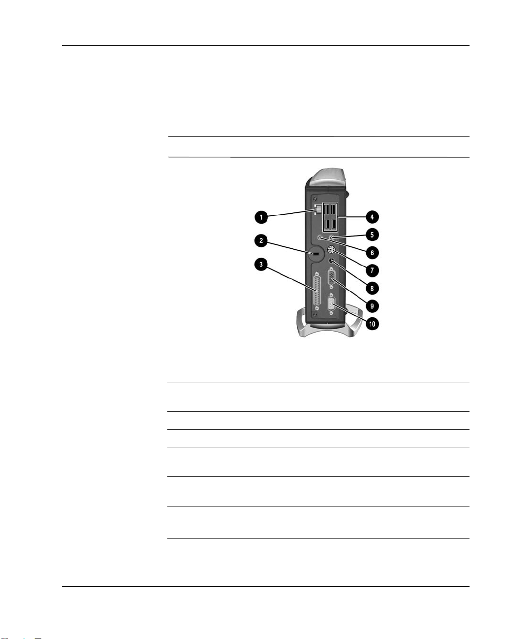
Rear Panel Components
Components may vary depending on the specific model.
✎
1-2
Rear Panel Components
1 Ethernet RJ-45 Connector 6 Line-out Audio (Headphone)
Connector
2 Cable Lock Slot 7 PS/2 Connector*
3 Parallel Connector** 8 Power Connector
4 Universal Serial Bus (USB)
Connectors (4)
5 Line-in Audio Connector
(Microphone)
* Not available on t5300, t5500, t5700 models.
**Not available on t5300 models.
www.hp.com
9 Monitor Connector
: Serial Connector**
Hardware Reference Guide
Page 7
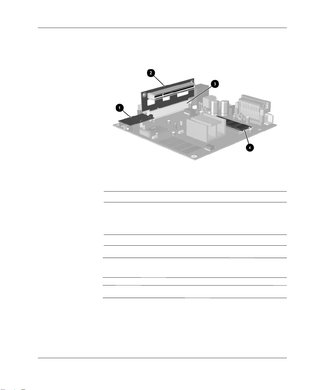
System Board Components
System Board Components
1 Flash Memory 3 PCI Slot*
Product Features
✎
✎
Hardware Reference Guide
2 PCI Riser Card* (optional;
for use with units having
optional PCI Expansion
Module)
* Not available on t5300 models.
Not all HP Compaq t5000 thin client models are flash memory,
SODIMMs, and/or PCI Expansion Module upgradeable.
32 MB of system RAM is reserved for processor usage.
www.hp.com
4 SODIMM Memory*
1-3
Page 8
Product Features
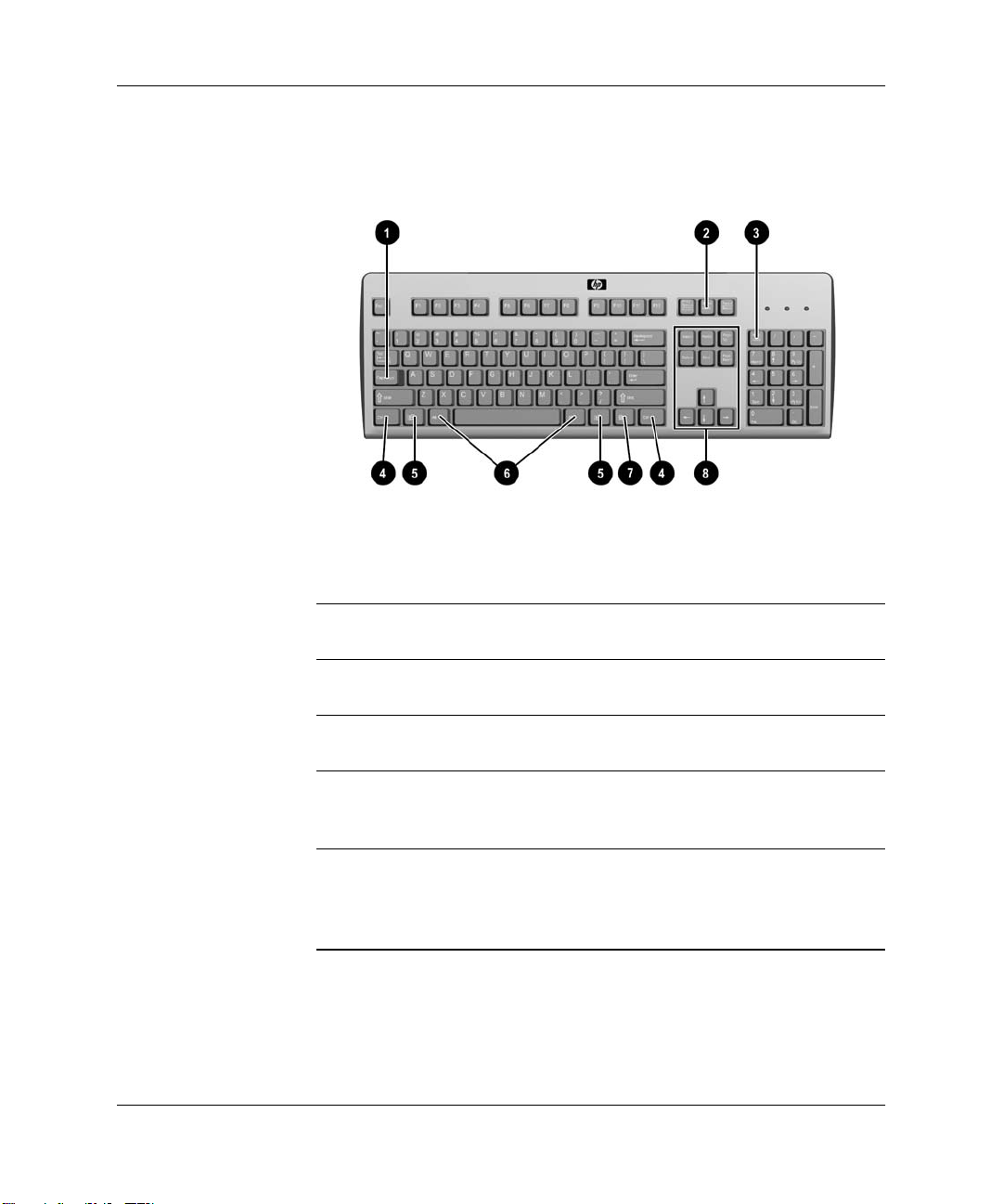
Using the Keyboard
Keyboard Features
Enhanced Keyboard Components
1 Caps Lock key Used to activate/deactivate the Caps
Lock feature.
1-4
2 Scroll Lock key Used to activate/deactivate the Scroll
Lock feature.
3 Num Lock key Used to activate/deactivate the Num
Lock feature.
key Used in combination with another key; its
4 Ctrl
effect depends on the application
software you are using.
1
5 Windows Logo Key
Used to open the Start menu in Microsoft
Windows. Used in combination with
other keys to perform other functions.
(See the following section.)
1
Keys available in select geographic regions.
www.hp.com
Hardware Reference Guide
Page 9

Enhanced Keyboard Components (Continued)
6 Alt Key Used in combination with another key; its
effect depends on the application
software you are using.
7 Application Key
1
Used (like the right mouse button) to open
pop-up menus in a Microsoft Office
application. May perform other functions
in other software applications.
Product Features
8 Editing Keys Includes the following:
1
Keys available in select geographic regions.
Windows Logo Key
Use the Windows Logo Key in combination with other keys to
perform certain functions available in the Windows operating
systems.
The Windows Logo Key is not supported on Linux-based systems.
✎
Windows Logo Key +
Windows Logo Key +
Windows Logo Key +
Windows Logo Key +
Insert, Home,
Page Up, Delete, End,
and
Page Down.
Holding down Ctrl and Alt while pressing
Delete allows you to restart the Thin
Client.
Tab
e
f
Ctrl
+
Switch between open items
Open My Computer
Search for a file or folder
Search for computers
f
Hardware Reference Guide
Windows Logo Key +
Windows Logo Key +
Windows Logo Key +
Windows Logo Key +
www.hp.com
m
+ mUndo Minimize All
Shift
break
Minimizes or restore all windows
Displays the System Properties
dialog box
r
Open the Run dialog box
1-5
Page 10

Product Features
Additional Function Keys
The following key combinations also work on HP Compaq t5000 thin
client models:
With Microsoft Windows XPe
Alt + Esc
Alt + Tab
Alt + Shift + Tab
With Microsoft Windows CE .NET
Alt + Esc
Alt + Tab
Special Mouse Functions
Most software applications support the use of a mouse. The function s
assigned to each mouse button depend on the software applications
you are using.
All HP Compaq t5000 thin client models ship with a USB scroll
✎
mouse.
Cycles through the minimized
applications.
Cycles through open applications.
Switches to the previous session.
Cycles through open applications.
Opens Task Manager.
1-6
www.hp.com
Hardware Reference Guide
Page 11

Serial Number Location
Each thin client has a unique serial number which is located on the
the thin client as shown in the following illustration. Keep this
number available for use when contacting HP customer service for
assistance.
Product Features
Hardware Reference Guide
Serial Number Location
www.hp.com
1-7
Page 12

Product Features
1-8
www.hp.com
Hardware Reference Guide
Page 13

Hardware Upgrades
General Hardware Installation Sequence
To ensure the proper installation of any thin client hardware option:
1. Back up any data if necessary.
2. If the thin client is on:
a. Shut the unit down.
b. Turn the unit and any other attached devices off.
c. Disc onnect the power cord from the wall outlet.
d. Disconnect any external devices or cables.
WARNING: To reduce the risk of personal injury from electrical shock
Å
and/or hot surfaces, be sure to disconnect the power cord from the wall
outlet and allow the internal system components to cool before touching.
2
Å
Ä
Hardware Reference Guide
WARNING: To reduce the risk of electrical shock, fire, or damage to the
equipment, do not plug telecommunications or telephone connectors into
the network interface controller (NIC) receptacles.
CAUTION: Static electricity can damage the electronic components of
the thin client or optional equipment. Before beginning these procedures,
ensure that you are discharged of static electricity by briefly touching a
grounded metal object. See Appendix C, “Electrostatic Discharge” for
more information.
www.hp.com
2-1
Page 14

Hardware Upgrades
3. Remove the side access panel. See the section “Removing and
Replacing the Side Access Panel” on page 2-3 for more
information on how to access the system board.
4. Remove, if necessary, any hardware that will be replaced.
5. Install any optional equipment. The following options are
available on select models:
❏
Flash Memory on page 2-5
❏
SODIMM Upgrade on page 2-6
❏
PCI Expansion Module on page 2-7
❏
MultiBay Hard Drive and Diskette Drive on page 2-10
More detailed instructions for installing thin client options are
✎
included in the option kits.
If it is necessary to replace the internal battery, refer to the
following section:
❏
Internal Battery on page 2-10.
2-2
6. Replace the side access panel. Refer to the section “Removing
and Replacing the Side Access Panel” on page 2-3 section for
instructions on this procedure.
7. Reconnect any external devices and power cords.
8. Turn on the monitor, the thin client, and any devices you want
to test.
9. Load any necessary drivers.
Many of the drivers necessary for installing optional thin client
✎
hardware can be found and downloaded from the HP website at
http://www.hp.com/country/us/eng/support.html.
10. Reconfigure the thin client, if necessary.
www.hp.com
Hardware Reference Guide
Page 15

Hardware Upgrades
Removing and Replacing the Side Access Panel
To install internal hardware options, you must remov e the si de access
panel and chassis cover as shown below.
WARNING: Before removing the side access panel, ensure that the thin
Å
client is turned off and that the power cord is disconnected from the
electrical outlet.
1. Remove the two back panel screws 1.
2. Pull the side panel off 2.
Hardware Reference Guide
Removing the Side Access Panel
www.hp.com
2-3
Page 16

Hardware Upgrades
3. Remove the chassis cover by removing the two screws 1 and
pulling the chassis cover 2 off.
4. Disconnect the speaker cable 3 from the system board.
Removing the Chassis Cover and Disconnecting the Speaker
To replace the cover, reverse the previous steps.
Installing Thin Client Options
There are several options available for installation on the thin client
such as flash memory , SODIM Ms, and security hardware (see
Appendix B, “Security Provisions” for security hardware
information). Not all thin clients support the same options. Visit the
HP website at
options/index.html
available options.
The following sections contain general installation instructions for
some of the available options. In all cases, see the specif ic installation
instructions that came with the thin client option.
Before beginning the installation process, review the “General
Hardware Installation Sequence” section earlier in this chapter, for
instructions on what to do before and after installing any options.
2-4
http://h18004.www1.hp.com/products/thinclients/
to see what options are supported and to order
www.hp.com
Hardware Reference Guide
Page 17

Flash Memory
Ä
✎
✎
Hardware Upgrades
If the thin client can be upgraded with optional flash memory , use the
following instructions as an overview of this procedure.
CAUTION: If necessary, back up any data before continuing the
installation.
In addition to following these instructions, follow the detailed
instructions that accompany the flash memory you have purchased.
1. Complete steps 1 through 4 of the “General Hardware Installation
Sequence” on page 2-1.
2. Remove any existing flash memory, if installed.
A set of needle-nose pliers may be required when removing the flash
memory module.
3. Verify the location of the round opening on the flash memory
card and align it with the plastic stem on the system board.
Hardware Reference Guide
4. Insert the new flash memory with the connectors facing down as
shown in the following illustration.
Installing Optional Flash Memory
5. Re-attach the side access panel.
www.hp.com
2-5
Page 18

Hardware Upgrades
6. Restore power to the thin client and turn it on.
7. Install the thin client firmware. For installation instructions, refer
SODIMM Upgrade
If the thin client can be upgraded with an optional SODIMM module,
use the following instructions as an overview of this procedure.
CAUTION: If necessary, back up any data before continuing the
Ä
installation.
In addition to following these instructions, follow the instructions that
✎
are applicable to the specific thin client option.
1. Complete steps 1 through 4 of the “General Hardware Installation
2. Remove any existing SODIMM if one is installed.
to the Troubleshooting Guide or the HP Compaq Thin Client
Imaging Tool white paper available on the HP website at
www.hp.com/products/thinclientsoftware
Sequence” on page 2-1.
.
2-6
3. Install the module into the socket at a 45° angle 1 until it clicks,
then rotate the module 2 into position as shown.
Installing an Optional SODIMM
4. Complete steps 6 through 10 of the “General Hardware
Installation Sequence” on page 2-1.
www.hp.com
Hardware Reference Guide
Page 19

PCI Expansion Module
If the thin client supports an optional PCI Expansion Module, follow
the instructions included in the option kit. The PCI Expansion
Module option kit includes the following components:
■
PCI riser card
■
PCI Expansion Module metal chassis cover (with speaker)
■
PCI Expansion Module plastic side access panel
Use the following instructions as an overview of this procedure.
In addition to following these instructions, follow the detailed
✎
instructions that accompany the PCI card you have purchased.
1. Complete steps 1 through 4 of the “General Hardware Installation
Sequence” on page 2-1.
2. Install the optional PCI riser card as shown in the following
diagram:
Hardware Upgrades
Hardware Reference Guide
Installing Optional PCI Riser Card
www.hp.com
2-7
Page 20

Hardware Upgrades
3. Connect the speaker cable from the PCI Expansion Module
chassis cover to the system board.
Connecting the Speaker
4. Install the PCI card 1 into the optional PCI riser card as shown in
the following figure.
5. Install the optional PCI Expansion Module chassis cover 2.
6. Secure the optional PCI Expansion Module chassis cover with the
four chassis screws 3.
2-8
Installing PCI Expansion Module and Chassis Cover
www.hp.com
Hardware Reference Guide
Page 21

Hardware Upgrades
7. Install the optional PCI Expansion Module side access panel 1.
8. Secure the panel with the two screws 2 as sho wn in the following
illustration.
Installing PCI Expansion Module Side Access Panel
9. Complete steps 6 through 10 of the “General Hardware
Installation Sequence” on page 2-1.
Hardware Reference Guide
To remove the PCI Expansion Module, reverse the previous steps.
www.hp.com
2-9
Page 22

Hardware Upgrades
Internal Battery
1. Complete steps 1 through 4 of the “General Hardware Installation
Sequence” on page 2-1.
2. Locate the battery on the system board.
3. Pull back on the clip 1 that is holding the battery in place, and
remove the battery 2.
4. Insert the new battery and position the clip back into place.
Removing and Replacing the Internal Battery
5. Complete steps 6 through 10 of the “General Hardware
Installation Sequence” on page 2-1.
MultiBay Hard Drive and Diskette Drive
The MultiBay hard drive and disk ette dri ve are a v ailable as options on
select thin client models. These are external USB compatible drives.
For additional installation information about these driv es visit
www.hp.com/products/thinclientsoftware
that accompany these option.
2-10
www.hp.com
or refer to the instructions
Hardware Reference Guide
Page 23

Specifications
HP Compaq t5000 thin client
Dimensions
Height
Width
Depth
Approximate Weight 2.6 lb 1.3 kg
Temperature Range (fanless design)*
Operating
(max. rate of change is 10
18
F per hour)
°
Nonoperating
(max. rate of change is 20
36
F per hour)
°
C per hour or
°
C per hour or
°
8.9 in
4.0 in
7. 7 i n
50° to 95° F
-22° to 140° F
22.6 cm
10.1 cm
19.6 cm
to 35° C
10
°
-30° to 60° C
A
*Specifications are at sea level with altitude
derating of 1° C/300m (1.8° F/1000ft) to a
maximum of 3Km (10,000ft), with no direct
sustained sunlight. Upper limit may be limited by
the type and number of options installed.
Relative Humidity (non-condensing)
Operating
(max. wet bulb temperature is 28
84.2
F)
°
Nonoperating
(max. wet bulb temperature is 38.7
101.6
Hardware Reference Guide
F)
°
C or
°
C or
°
10–90%
5–95%
www.hp.com
10–90%
5–95%
A-1
Page 24

Specifications
Maximum Altitude (unpressurized)
Operating
10,000 ft
3048 m
(max. allowed rate of change is 457m per
minute or 1500 ft per minute)
Nonoperating
30,000 ft
9144 m
(max. allowed rate of change is 457m per
minute or 1500 ft per minute)
*Value may be limited by type and number of
options installed.
Power Supply
Operating Voltage Range
Rated Line Frequency
90–264 VAC
47–63 Hz
90–264 VAC
47–63 Hz
Power Output (maximum) 40 W 40 W
Rated Input Current (maximum) 4.0 A 4.0 A
Heat Dissipation
On
Off
136.4 BTU/hr
2.94 BTU/hr
34.4 kg-cal/hr
0.74 kg-cal/hr
A-2
www.hp.com
Hardware Reference Guide
Page 25

Securing the Thin Client
The HP Compaq t5000 thin client models are designed to accept a
security cable lock. A separate security cable lock option is available
for thin clients. This cable lock prevents the thin client from being
removed from its location. To order this option visit the HP website at
http://h18004.www1.hp.com/products/thinclients/
options/index.html.
1. Locate the cable lock slot 1 on the back panel.
2. Insert the cable lock 2 and use the key 3 to lock it.
B
Security Provisions
Hardware Reference Guide
Securing the Thin Client
www.hp.com
B-1
Page 26

Security Provisions
Mounting Bracket
The HP Compaq t5000 thin client models are designed to accept a
mounting bracket. This mounting bracket can be used to attach the
thin client to a wall or desk. To order this option visit the HP website
http://h18004.www1.hp.com/products/thinclients/
at
options/index.html.
B-2
Mounting Bracket for the Thin Client
www.hp.com
Hardware Reference Guide
Page 27

Electrostatic Discharge
A discharge of static electricity from a finger or other conductor may
damage system boards or other static-sensitive devices. This type of
damage may reduce the life expectancy of the device.
Preventing Electrostatic Damage
To prevent electrostatic damage, observe the following precautions:
■
Avoid hand contact by transporting and storing products in
static-safe containers.
■
Keep electrostatic-sensitive parts in their containers until they
arrive at static-free workstations.
■
Place parts on a grounded surface before removing them from
their containers.
■
Avoid touching pins, leads, or circuitry.
C
Hardware Reference Guide
■
Always be properly grounded when touching a static-sensitive
component or assembly.
www.hp.com
C-1
Page 28

Electrostatic Discharge
Grounding Methods
There are several methods for grounding. Use one or more of
the following methods when handling or installing
electrostatic-sensitive parts:
■
Use a wrist strap connected by a ground cord to a grounded
Thin Client chassis. Wrist straps are flexible straps with a
minimum of 1 megohm +/- 10 percent resistance in the ground
cords. To provide proper grounding, wear the strap snug against
the skin.
■
Use heelstraps, toestraps, or bootstraps at standing workstations.
Wear the straps on both feet when standing on conductive floors
or dissipating floor mats.
■
Use conductiv e field service tools.
■
Use a portable field service kit with a folding static-dissipating
work mat.
If you do not have any of the suggested equipment for proper
grounding, contact an HP authorized dealer, reseller, or service
provider.
C-2
For more information on static electricity, contact an HP authorized
✎
dealer, reseller, or service provider.
www.hp.com
Hardware Reference Guide
Page 29

Routine Thin Client Care and Shipping
Information
Routine Thin Client Care
Follow these suggestions to take care of the thin client:
■
Operate the thin client on a sturdy, level surface. Leave a 3-inch
(7.6-cm) clearance around the air vents to permit the required
airflow.
■
Never operate the thin client with the outside panel removed.
■
Never restrict the airflo w into the thin client b y blocking the v ents
or air intake.
■
Keep the thin client away from excessive moisture, direct
sunlight, and extremes of heat and cold. For information about
the recommended temperature and humidity ranges for the thin
client, see Appendix A, “Specifications” in this guide.
D
Hardware Reference Guide
■
Keep liquids away from the thin client and keyboard.
■
Turn off the thin client before you do either of the following:
❏
Wipe the exterior of the thin client with a soft, damp cloth
as needed. Using cleaning products may discolor or damage
the finish.
❏
Occasionally clean the air vents of the thin client. Lint and
other foreign matter can block the vents and limit the airflow.
www.hp.com
D-1
Page 30

Routine Thin Client Care and Shipping Information
Shipping Preparation
Follow these suggestions when preparing to ship the thin client:
1. Turn off the thin client and external devices.
2. Disconnect the power cord from the electrical outlet, then from
the thin client.
3. Disconnect the system components and e xt ern al devices from
their power sources, then from the thin client.
4. Pack the system co mponents and e xternal de vices in their original
packing boxes or similar packaging with sufficient packing
material to protect them.
For environmental nonoperating ranges, see Appendix A,
✎
“Specifications” in this guide.
Important Service Repair Information
In all cases, remove and safeguard all external options before
returning the thin client to HP for repair or exchange.
D-2
In countries that support customer mail-in repair by returning the
same unit to the customer, HP makes every effort to return
the repaired HP with the same internal memory and flash modules
that were sent.
In countries that do not support customer mail-in repair by returning
the same unit to the customer, all internal options should be removed
and safeguarded in addition to the external options. The thin client
should be restored to the original configuration before returning it to
HP for repair.
www.hp.com
Hardware Reference Guide
Page 31

Index
A
Altiris Deployment Solution 1–1
C
cable lock
installing B–1
slot location 1–2
cautions
backing up data 2–5
static electricity 2–1
components
keyboard 1–4
mouse 1–6
rear panel 1–2
E
electrostatic discharge C–1
F
flash memory
installing 2–5
location 1–3
G
grounding methods C–2
H
hardware
specifications A–1
upgrades 2–1
headphone connector 1–2
I
installation sequence 2–1
installing
flash memory 2–5
memory 2–6
MultiBay diskette drive 2–10
MultiBay hard drive 2–10
K
keyboard 1–4
function keys 1–6
layout 1–4
Windows logo key 1–5
L
line-in audio connector 1–2
line-out audio connector
1–2
M
memory
installing 2–6
socket location 1–3
monitor connector 1–2
mouse
1–6
O
options
installing 2–1, 2–4
supported 2–2
P
PCI
Expansion Module 2–7
riser card 2–7
slot location 1–3
Hardware Reference Guide
www.hp.com
Index-1
Page 32

Index
PCI Expansion Module
installing 2–7
kit contents 2–7
removing 2–9
R
rear panel components 1–2
removing
PCI Expansion Module 2–9
side access panel 2–3
SODIMMs 2–6
RJ-45 connector 1–2
routine care
D–1
S
security provisions B–1
1–7
D–2
2–1
1–2
D–2
serial connector
serial number
service repair
shipping preparation
shutting down
side access panel
removing 2–3
software
Altiris Deployment Solution 1–1
pre-installed 1–1
specifications A–1
T
thin client features 1–1
U
USB connector 1–2
W
warnings
electric shock 2–1
fire 2–1
Index-2
www.hp.com
Hardware Reference Guide
 Loading...