

Page 1
Agilent
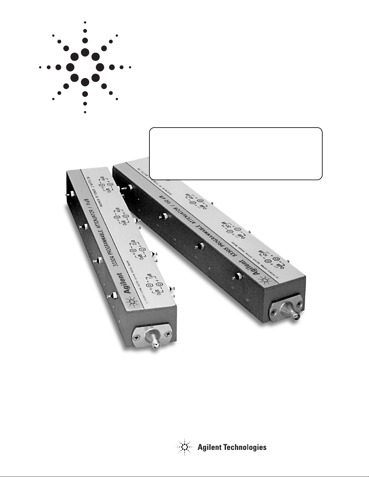
33304/5
Programmable
Step Attenuators
Data Sheet
Features and description
•
Rapid switching (less than 0.05 second)
•
High repeatability (0.05 dB typical)
•
Broadband (DC to 18 GHz)
•
Two ranges and step sizes
Discontinued Product Information
— For Support Reference Only —
Information herein, may refer to products/services no longer supported. We regret any
inconvenience caused by obsolete information. For the latest information on Agilent’s
test and measurement products go to: www.agilent.com/find/products
In the US, call Agilent Technologies at 1-800-829-4444
(any weekday between 8am–5pm in any U.S. time zone)
World-wide Agilent sales office contact information is available at:
www.agilent.com/find/contactus
Page 2

2
The 33300 Programmable Step Attenuators provide a fast and precise means
for electrically controlling the level of signal attenuation in automatic test
systems, receivers, and other RF equipment. They provide attenuation up
to 110 dB in 1 or 10 dB steps over a frequency range of dc to 18 GHz.
The products are defined as:
Model no. Total attenuation Step size
dB dB
33304 11 1
33305 110 10
The 33300 series attenuators utilize a unique operating principle. Magnetic
latching solenoids are used to switch individual attenuation elements
(tantalum resistive films on sapphire substrates) into and out of contact
with a 50-ohm transmission line. Each unit is comprised of three or
four attenuation sections. By energizing the appropriate solenoid, any
combination of these sections may be put across the 50-ohm transmission
line to give the desired levels of attenuation.
The extreme stability of the sapphire tantalum attenuator pads, combined
with the elimination of sliding contacts, gives rise to a product that has as
number of important operational features. Among these are fast switching
speed, excellent repeatability, compact size, long life, and high stability.
Magnetic latching solenoids move the transmission line into and out of
contact with the sapphire attenuator elements. These solenoids are supplied
with coils for 24-volt operation. The 24-volt coil can be run at up to 30 volts.
Because the solenoids are of the latching type, power need not be
continuously maintained to keep the solenoid in either the in or the out
position. It is sufficient to pulse the solenoid for 30 milliseconds at its rated
voltage to change states. To change states the polarity across the terminals
must be reversed. However, both terminals are “floating,” so either can
be grounded. Thus, unipolar power supplies are sufficient for controlling
these units.
For switching speeds faster than 30 ms, this pulse voltage can be increased.
A maximum of double the rated voltage may be put across the solenoids
in such cases, but pulse width should be limited to keep average solenoid
power below 3.3 watts per section.
Indicator contacts, which allow the user to determine whether a given
section is engaged or not, can be included. These contacts are in their
open position when the appropriate attenuator cards are not engaged.
The contacts close, and remain closed, when the appropriate card moves
into contact with the transmission line.
The 33300 series is available with any combination of 3 mm, 7 mm or
Type N connectors. A three-digit code specifies these options. The first
digit is always 0. The second digit calls out port 1, the third, port 2.
See figure 2 for details.
Description
Page 3

3
Figure 3. Outline drawings
Figure 2. Ordering example
Figure 1. Electrical diagram and
programming table
Page 4

Electrical
Frequency range: DC-18 GHz
Characteristic impedance: 50 ohms
Attenuation ranges:
Model Range (dB) Step size (dB)
33304 0–11 1
33305 0–110 10
Life, minimum: 1,000,000 steps each section.
Power sensitivity: 0.001 dB/dB/ watt.
Attenuation temperature coefficient: Less than 0.0001 dB/dB° C
Repeatability, typical:
DC–12.4 GHz 0.03 dB
12.4–18 GHz 0.05 dB
Attenuation accuracy (±dB) referenced from 0 dB setting:
33304
DC–4 GHz 0.2 0.2 0.3 0.3 0.3 0.3 0.4 0.4 0.4 0.4 0.5
4–12.4 GHz 0.3 0.3 0.4 0.4 0.4 0.4 0.5 0.5 0.5 0.5 0.6
12.4–18 GHz 0.5 0.5 0.6 0.6 0.7 0.8 0.8 0.8 0.8 0.8 0.9
33305
Frequency range Attenuator setting (dB)
DC–12.4 GHz 0.5 0.7 0.9 1.2 1.5 1.8 2.1 2.4 2.7 3.0 3.3
12.4–18 GHz 0.6 0.8 1.2 1.6 2.0 2.4 2.8 3.2 3.6 4.0 4.4
Note: The attenuation sections 3 and 4 of both the 33304 and 33305 have equal attenuation values.
There are attenuator configurations which require only one of those to be activated. The above
accuracy specifications are guaranteed only when section 3 is used in preference to section 4.
VSWR: 33304 and 33305
Frequency range Connector type
SMA Type N 7 mm
DC–8 GHz 1.5 1.45 1.4
8–12.4 GHz 1.6 1.55 1.5
12.4–18 GHz 1.9 1.8 1.7
Solenoid voltage and nominal coil impedance:
Models Solenoid voltage Coil impedance
33304B/D 24 to 30 Vdc 262 ohms
33305B/D 0.192 ohms
Power required to switch one section: 3.3 watts.
(Continuous operation of solenoids requires 10 watts dissipation in heat sink.)
Environmental
Temperature, non-operating: –40° C to +85° C.
Temperature, operating: –20° C to 55° C.
Altitude, operating: 25,000 ft.
Vibration, operating: 5 – 500 – 5 Hz, 15 min./cycle, 3 hours/axis. 0.100-inch D.A. to 31 Hz,
5 g’s to 500 Hz, with and without power applied to the relays in both positions.
Ordering information
See figure 2 for ordering information.
Specifications
www.agilent.com/find/emailupdates
Get the latest information on the products and
applications you select.
www.agilent.com
Agilent Technologies’ Test and Measurement
Support, Services, and Assistance
Agilent Technologies aims to maximize the value you
receive, while minimizing your risk and problems. We
strive to ensure that you get the test and measurement
capabilities you paid for and obtain the support you
need. Our extensive support resources and services
can help you choose the right Agilent products for your
applications and apply them successfully. Every
instrument and system we sell has a global warranty.
Two concepts underlie Agilent’s overall support policy:
“Our Promise” and “Your Advantage.”
Our Promise
Our Promise means your Agilent test and measurement
equipment will meet its advertised performance
and functionality. When you are choosing new
equipment, we will help you with product information,
including realistic performance specifications and
practical recommendations from experienced test
engineers. When you receive your new Agilent
equipment, we can help verify that it works properly
and help with initial product operation.
Your Advantage
Your Advantage means that Agilent offers a wide range
of additional expert test and measurement
services, which you can purchase according to your
unique technical and business needs. Solve problems
efficiently and gain a competitive edge by contracting
with us for calibration, extra-cost upgrades, out-ofwarranty repairs, and onsite education and training,
as well as design, system integration, project
management, and other professional engineering
services. Experienced Agilent engineers and
technicians worldwide can help you maximize your
productivity, optimize the return on investment of your
Agilent instruments and systems, and obtain
dependable measurement accuracy for the life of those
products.
For more information on Agilent Technologies’
products, applications or services, please contact
your local Agilent office.
Phone or Fax
United States: Korea:
(tel) 800 829 4444 (tel) (080) 769 0800
(fax) 800 829 4433 (fax) (080) 769 0900
Canada: Latin America:
(tel) 877 894 4414 (tel) (305) 269 7500
(fax) 800 746 4866 Taiwan:
China: (tel) 0800 047 866
(tel) 800 810 0189 (fax) 0800 286 331
(fax) 800 820 2816 Other Asia Pacific
Europe: Countries:
(tel) 31 20 547 2111 (tel) (65) 6375 8100
Japan: (fax) (65) 6755 0042
(tel) (81) 426 56 7832 Email: tm_ap@agilent.com
(fax) (81) 426 56 7840
Contacts revised: 09/26/05
The complete list is available at:
www.agilent.com/find/contactus
Product specifications and descriptions in this
document subject to change without notice.
© Agilent Technologies, Inc. 2001, 2006
Printed in USA, July 13, 2006
5953-2354
Agilent Email Updates
 Loading...