

Page 1
Page 2
HEWLETT
PACKARD
CERTIFICATION
Hewlett-Packard Company certifies that this product met its published specifications at the time of shipment
from the factory. Hewlett-Packard further certifies that its calibration measurements are traceable to the United
States National Bureau of Standards, to the extent allowed by the Bureau's calibration facility, and to the calibration facilities of other International Standards Organization members.
WARRANTY
This Hewlett-Packard product is warranted against defects in material and workmanship for a period of one
year from date of shipment. During the warranty period, Hewlett-Packard Company will, at its option, either
repair or replace products which prove to be defective.
For warranty service or repair, this product must be returned to a service facility designated by
shall prepay shipping charges to -hp- and -hp- shall pay shipping charges to return the product to Buyer. However,
Buyer shall pay all shipping charges, duties, and taxes for products returned to
HP software and firmware products which are designated by HP for use with a hardware product, when properly
installed on that hardware product, are warranted not to fail to execute their programming instructions due
to defects in materials and workmanship. If HP receives notice of such defects during their warranty period,
HP shall repair or replace software media and firmware which do not execute their programming instructions
due to such defects. HP does not warrant that the operation of the software, firmware or hardware shall be
uninterrupted or error free.
LIMITATION OF WARRANTY
The foregoing warranty shall not apply to defects resulting from improper or inadequate maintenance by
Buyer, Buyer-supplied software or interfacing, unauthorized modification or misuse, operation outside of the
environmental specifications for the product, or improper site preparation or maintenance.
NO OTHER WARRANTY IS EXPRESSED OR IMPLIED. HEWLETT-PACKARD SPECIFICALLY DISCLAIMS THE
IMPLIED WARRANTIES OF MERCHANTABILITY AND FITNESS FOR A PARTICULAR PURPOSE.
EXCLUSIVE REMEDIES
THE REMEDIES PROVIDED HEREIN ARE BUYER'S SOLE AND EXCLUSIVE REMEDIES. HEWLETT-PACKARD
SHALL NOT BE LIABLE FOR ANY DIRECT, INDIRECT, SPECIAL, INCIDENTAL, OR CONSEQUENTIAL
DAMAGES, WHETHER BASED ON CONTRACT, TORT, OR ANY OTHER
-hp- from another country.
LEGAL THEORY.
-hp-. Buyer
ASSISTANCE
Product maintenance agreements and other customer assistance agreements are available for Hewlett-Packard
products.
For any assistance, contact your nearest Hewlett-Packard Sales and Service Office. Addresses are provided at
the back of this manual.
Page 3
Reproduced With Permission Courtesy Agilent Technologies, Inc.
Page 4
HEWLETT
PACKARD
SAFETY SUMMARY
The following general safety precautions must be observed during all phases of operation, service, and repair
of this instrument. Failure to comply with these precautions or with specific warnings elsewhere in this manual
violates safety standards of design, manufacture, and intended use of the instrument. Hewlett-Packard Company assumes no liability for the customer's failure to comply with these requirements. This is a Safety Class
1
instrument.
GROUND THE INSTRUMENT
To minimize shock hazard, the instrument chassis and cabinet must be connected to an electrical ground.
The instrument is equipped with a three conductor ac power cable. The power cable must either be plugged
into an approved three-contact electrical outlet or used with a three-contact to two-contact adapter with the
grounding wire (green) firmly connected to an electrical ground (safety ground) at the power outlet. The power
(lEC)
jack and mating plug of the power cable meet International Electrotechnical Commission
DO NOT OPERATE IN AN EXPLOSIVE ATMOSPHERE
Do not operate the instrument in the presence of flammable gases or fumes. Operation of any electrical instru-
ment in such an environment constitutes a definite safetv hazard.
safety standards.
KEEP AWAY FROM LIVE CIRCUITS
Operating personnel must not remove instrument covers. Component replacement and internal adjustments
must be made by qualified maintenance personnel. Do not replace components with power cable connected.
Under certain conditions, dangerous voltages may exist even with the power cable removed. To avoid injuries,
always disconnect power and discharge circuits before touching them.
DO NOT SERVICE OR ADJUST ALONE
Do not attempt internal service or adjustment unless another person, capable of rendering first aid and resus-
citation, is present.
DO NOT SUBSTITUTE PARTS OR MODIFY INSTRUMENT
Because of the danger of introducing additional hazards, do not install substitute parts or perform any unautho-
rized modification to the instrument. Return the instrument to a Hewlett-Packard Sales and Service Office
for service and repair to ensure that safety features are maintained.
DANGEROUS PROCEDURE WARNINGS
Warnings, such as the example below, precede potentially dangerous procedures throughout this manual. Instruc-
tions contained in the warnings must be followed.
Dangerous voltages, capable of causing death, are present in this instrument. Use
extreme caution when handling, testing, and adjusting.
Page 5
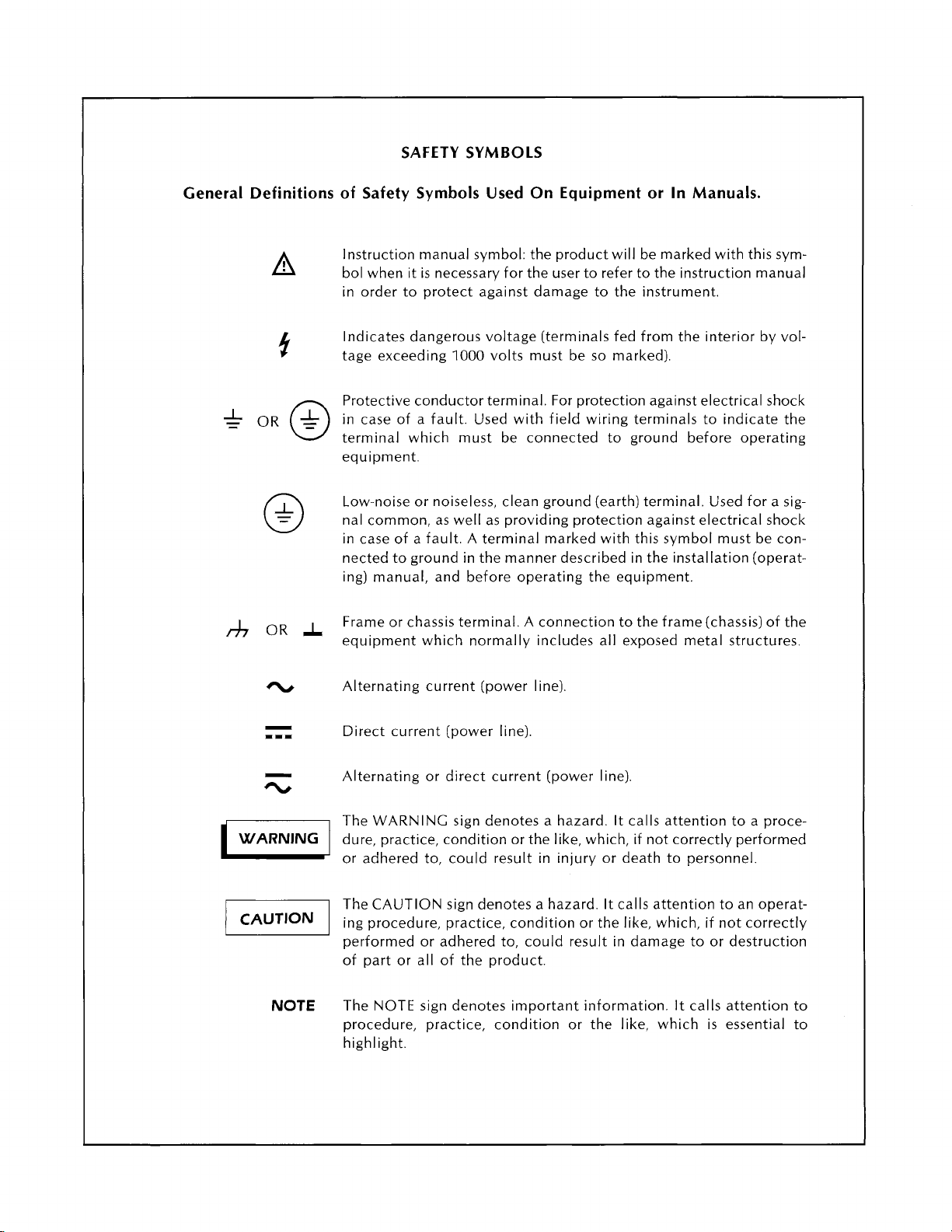
SAFETY SYMBOLS
General Definitions of Safety Symbols Used On Equipment or In Manuals.
Instruction manual symbol: the product will be marked with this symbol when it is necessary for the user to refer to the instruction manual
in order to protect against damage to the instrument.
Indicates dangerous voltage (terminals fed from the interior by vol-
1000
tage exceeding
Protective conductor terminal. For protection against electrical shock
in case of a fault. Used with field wiring terminals to indicate the
terminal which must be connected to ground before operating
equipment.
Low-noise or noiseless, clean ground (earth) terminal. Used for a signal common, as well as providing protection against electrical shock
in case of a fault. A terminal marked with this symbol must be connected to ground in the manner described in the installation (operat-
ing) manual, and before operating the equipment.
volts must be so marked).
WARNING
a
NOTE
Frame or chassis terminal. A connection to the frame (chassis) of the
equipment which normally includes all exposed metal structures.
Alternating current (power line).
Direct current (power line).
Alternating or direct current (power line)
The WARNING sign denotes a hazard. It calls attention to a procedure, practice, condition or the like, which, if not correctly performed
or adhered to, could result in injury or death to personnel.
The CAUTION sign denotes a hazard. It calls attention to an operat-
ing procedure, practice, condition or the like, which, if not correctly
performed or adhered to, could result in damage to or destruction
of part or all of the product.
The NOTE sign denotes important information. It calls attention to
procedure, practice, condition or the like, which is essential to
highlight.
Page 6
Page 7
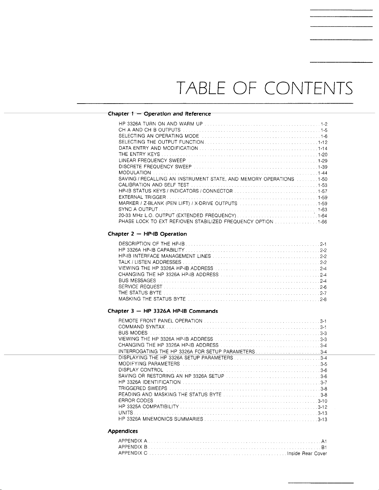
TABLE
OF CONTENTS
.
HP 3326A TURN ON AND WARM UP
CH A AND CH B OUTPUTS
SELECTING AN OPERATING MODE
SELECTING THE OUTPUT FUNCTION
DATA ENTRY AND MODIFICATION
THE ENTRY KEYS
LINEAR FREQUENCY SWEEP
DISCRETE FREQUENCY SWEEP
MODULATION
SAVING
CALIBRATION AND SELF TEST
HP-IB STATUS KEYS
EXTERNAL TRIGGER
MARKER
SYNC A OUTPUT
20-33 MHz L.O. OUTPUT (EXTENDED FREQUENCY)
PHASE LOCK TO EXT REFIOVEN STABILIZED FREQUENCY OPTION
Chapter
DESCRIPTION OF THE HP-IB
HP 3326A HP-IB CAPABILITY
HP-IB INTERFACE MANAGEMENT LINES
TALK
VIEWING THE HP 3326A HP-IB ADDRESS
CHANGING THE HP 3326A HP-IB ADDRESS
BUS MESSAGES
SERVICE REQUEST
THE STATUS BYTE
MASKING THE STATUS BYTE
I
RECALLING AN INSTRUMENT STATE. AND MEMORY OPERATIONS 1-50
1
Z-BLANK (PEN LIFT) 1 X-DRIVE OUTPUTS
2
.
HP-IB
I
LISTEN ADDRESSES
........ ......
I
INDICATORS / CONNECTOR
Operation
.... .... ....
, , ,
.... .......
...... ......
.......
. . . . .
. . ........ . .
...
. . . . ... ...
... . . ...
... ... . . . . .....
........ ... ....
. . .......
. . .......
. .
.... .........
........ .....
....... . .
. .
.....
. . ....
. . ....
...
.......
. . .
1-2
1-5
1-6
1-12
1-14
1-20
1-29
1-39
1-44
1-53
1-57
1-59
1-59
1-63
1-64
1-66
2-1
2-2
2-2
2-2
2-4
2-4
2-4
2-6
2-7
2-8
Chapter
3
.
HP
3326A
REMOTE FRONT PANEL OPERATION
COMMAND SYNTAX
BUS MODES
VIEWING THE HP 3326A HP-IB ADDRESS
CHANGING THE HP 3326A HP-IB ADDRESS
INTERROGATING THE HP 3326A FOR SETUP PARAMETERS
DISPLAYING THE HP 3326A SETUP PARAMETERS
MODIFYING PARAMETERS
DISPLAY CONTROL
SAVING OR RESTORING AN HP 3326A SETUP
HP 3326A IDENTIFICATION
TRIGGERED SWEEPS
READING AND MASKING THE STATUS BYTE
ERROR CODES
HP 3325A COMPATIBILITY
UNITS
HP 3326A MNEMONICS SUMMARIES
HP-IB
Commands
.... . . ...
............ ...
...... ........
..... ...... . .
. . ...
..................
....
. . ....
........
.....
........ . .
.... . . . .
. . . . .....
...........
....
......
. . ....
....
...
Appendices
APPENDIX A A 1
APPENDIX
APPENDIX C lns~de Rear Cover
B
3-1
3-1
3-3
3-3
3-4
3-4
....
3-4
3-5
3-6
3-6
3-7
3-10
3-1 2
3-13
3-13
3-8
3-8
B1
Page 8
Page 9

CHAPTER
I
OPERATION AND REFERENCE
Page 10
Chapter
1
.
Table of Contents
HP 3326A TURN ON AND WARM UP
CH A AND CH B OUTPUTS
AN
SELECTING
OPERATING MODE
...................................
SELECTING THE OUTPUT FUNCTION
DATA ENTRY AND MODIFICATION
THE ENTRY KEYS 1-20
LINEAR FREQUENCY SWEEP
..........................................
................................
DISCRETE FREQUENCY SWEEP 1-39
MODULATION
SAVING
I
AND
MEMORY OPERATIONS
CALIBRATION AND SELF TEST
HP-IB STATUS KEYS
EXTERNAL TRIGGER
MARKER
SYNC A OUTPUT 1.63
20-33
MHz
.............................................
RECALLING AN INSTRUMENT STATE,
................................
I
INDICATORS I CONNECTOR
........................................
I
Z-BLANK (PEN LIFT) I X-DRIVE OUTPUTS
..........................................
L.O.
OUTPUT (EXTENDED FREQUENCY)
........................
1.2
1-5
..........................
..........................
..........................
1-6
1-12
1-14
1-29
..............................
1-44
...............................
1.50
1.53
...............
1.57
1.59
.............
............
1-59
1-64
PHASE LOCK TO EXT REFIOVEN STABILIZED
FREQUENCY OPTION 1-66
......................................
Page 11
Qservice ----- This Document is a complete scan from the Original HP - Agilent Manual ----- Qservice
Page 12
Turn
on and Warm
up
HP 3326A TURN
ON
Turn On and Power
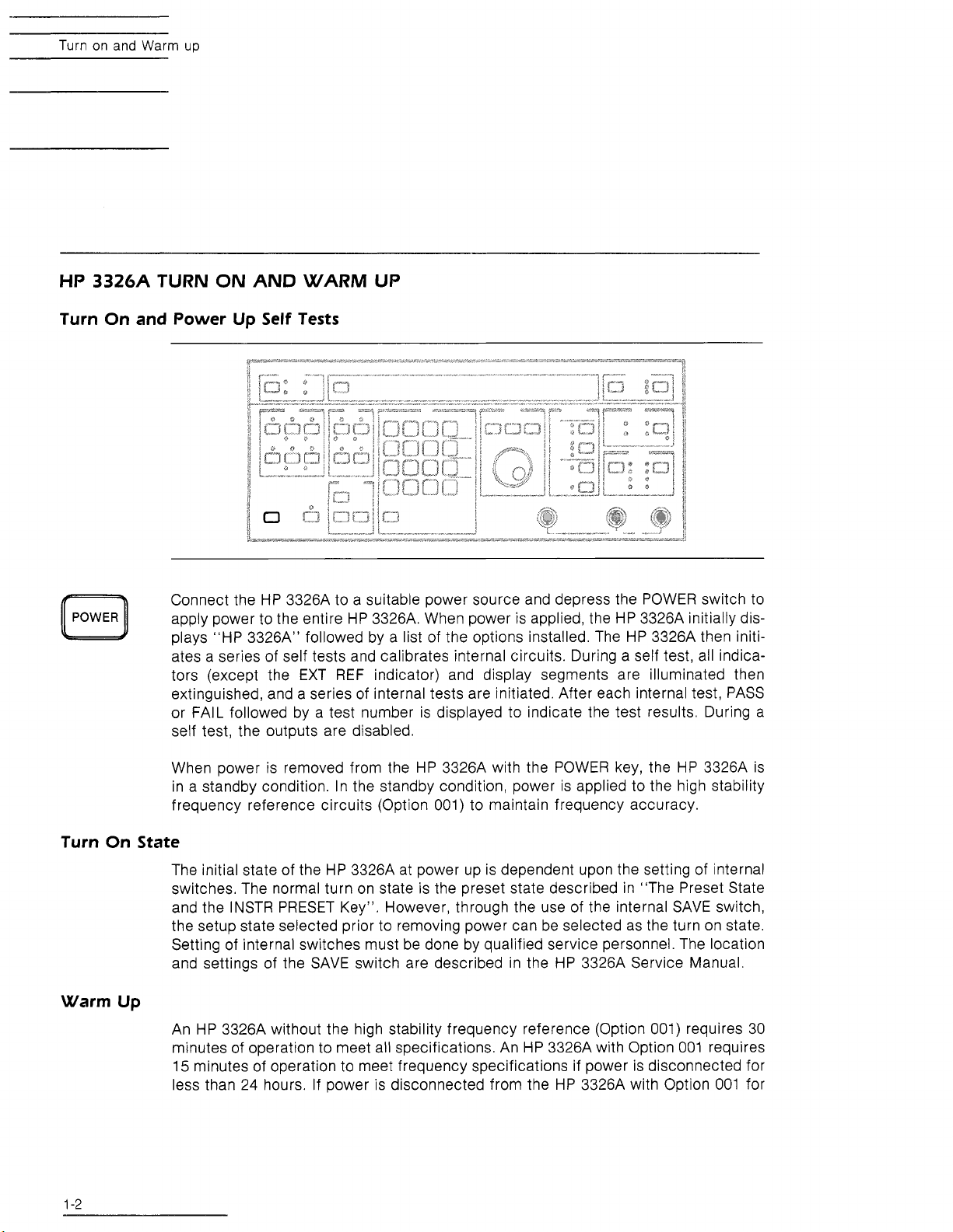
Connect the HP 3326A to a suitable power source and depress the POWER switch to
POWER
apply power to the entire HP 3326A. When power is applied, the HP 3326A initially displays "HP 3326A" followed by a list of the options installed. The HP 3326A then initiates a series of self tests and calibrates internal circuits. During a self test, all indicators (except the EXT REF indicator) and display segments are illuminated then
extinguished, and a series of internal tests are initiated. After each internal test, PASS
FAIL followed by a test number is displayed to indicate the test results. During a
or
self test, the outputs are disabled.
AND WARM UP
Up
Self
Tests
When power is removed from the HP 3326A with the POWER key, the
frequency reference circuits (Option 001) to maintain frequency accuracy.
Turn On State
The initial state of the HP 3326A at power up is dependent upon the setting of internal
the setup state selected prior to removing power can be selected as the turn on state.
Warm
Up
An HP 3326A without the high stability frequency reference (Option 001) requires 30
HP
3326A is
in a standby condition. In the standby condition, power is applied to the high stability
switches. The normal turn on state is the preset state described in "The Preset State
and the INSTR PRESET Key". However, through the use of the internal SAVE switch,
Setting of internal switches must be done by qualified service personnel. The location
and settings of the SAVE switch are described in the HP
minutes of operation to meet all specifications. An HP 3326A with Option 001 requires
15
minutes of operation to meet frequency specifications if power is disconnected for
less than 24 hours. If power is disconnected from the HP 3326A with Option 001 for
3326A Service Manual.
Page 13
Turn
on
and Warm up
more than 24 hours, up to 72 hours of operation may be required to meet frequency
001
specifications. The HP 3326A with Option
requires 30 minutes of operation to meet
other specifications.
NOTE
When power is removed from the HP
the POWER key, the
dition. In the standby condition, power is applied
to the high stability frequency reference circuits
00
(Option
1)
The Preset State and the lnstr Preset Key
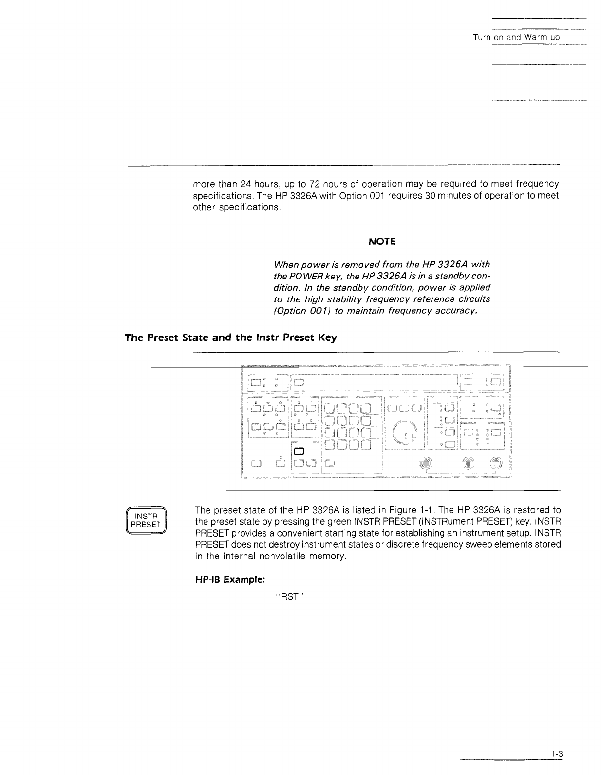
INSTR
PRESET
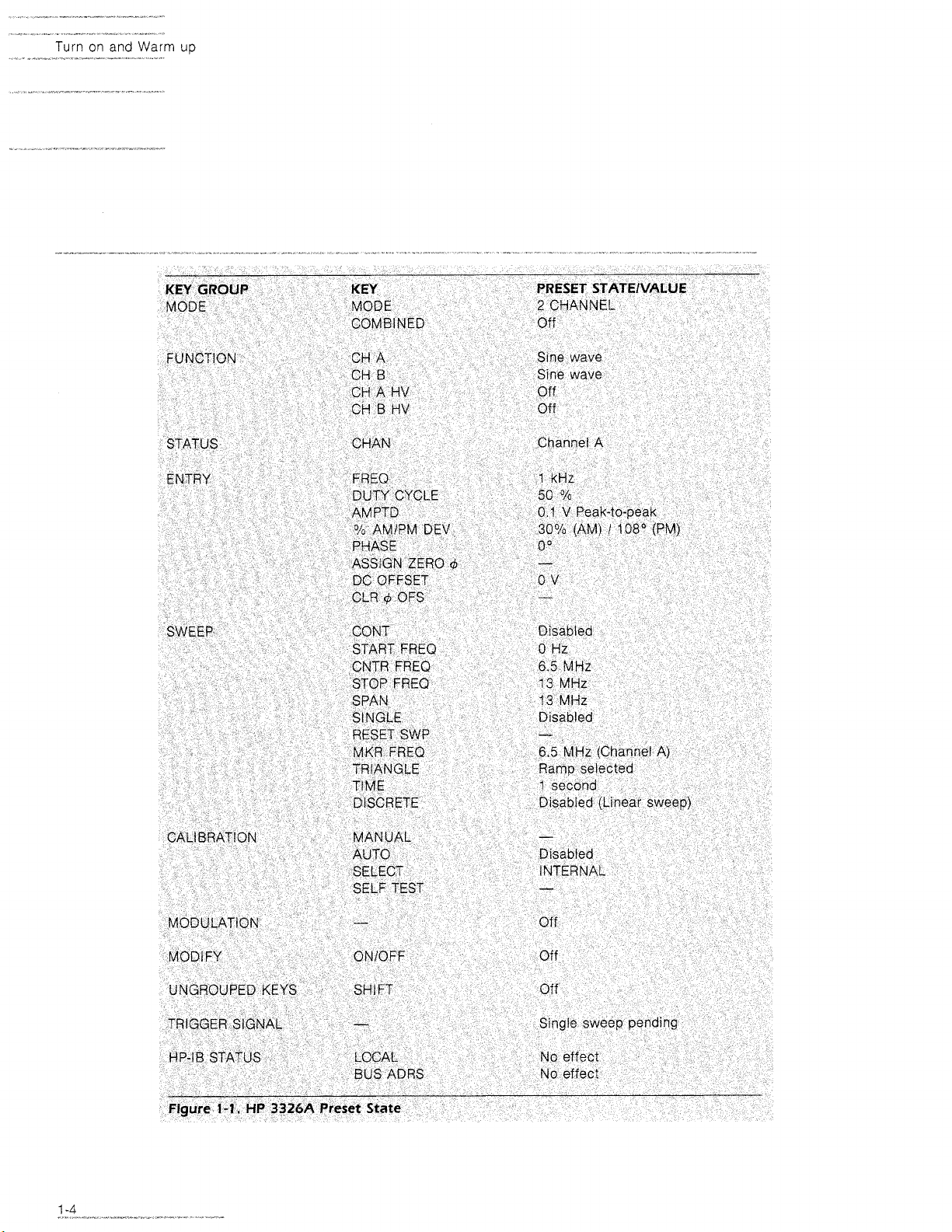
The preset state of the HP 3326A is listed in Figure
the preset state by pressing the green INSTR PRESET (INSTRument PRESET) key. INSTR
PRESET provides a convenient starting state for establishing an instrument setup. INSTR
PRESET does not destroy instrument states or discrete frequency sweep elements stored
in the internal nonvolatile memory.
3326A
HP
3326A
to maintain frequency accuracy.
is in a standby con-
1-1.
The HP 3326A is restored to
with
HP-IB
Example:
"RST"
Page 14
Turn on and Warm
up
Page 15
CH A and
CH
B Outputs
CH A AND
CH
B
OUTPUTS
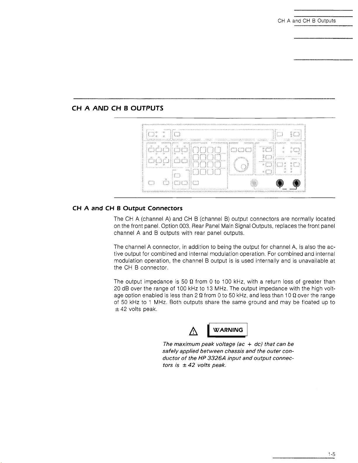
CH A and CH B Output Connectors
The CH A (channel
on the front panel. Option 003, Rear Panel Main Signal Outputs, replaces the front panel
A
channel
The channel
tive output for combined and internal modulation operation. For combined and internal
modulation operation, the channel B output is is used internally and is unavailable at
the CH B connector.
and B outputs with rear panel outputs.
A
A)
and CH B (channel B) output connectors are normally located
connector, in addition to being the output for channel
A,
is also the ac-
Q
The output impedance is 50
20 dB over the range of 100 kHz to 13 MHz. The output impedance with the high voltage option enabled is less than 2
of 50 kHz to 1 MHz. Both outputs share the same ground and may be floated up to
+
42 volts peak.
The maximum peak voltage lac + dc) that can be
safely applied between chassis and the outer conductor of the
tors is
from 0 to 100 kHz, with a return loss of greater than
Q
from 0 to 50 kHz, and less than 10 D over the range
HP
+
42
3326A
volts peak.
input and output connec-
Page 16
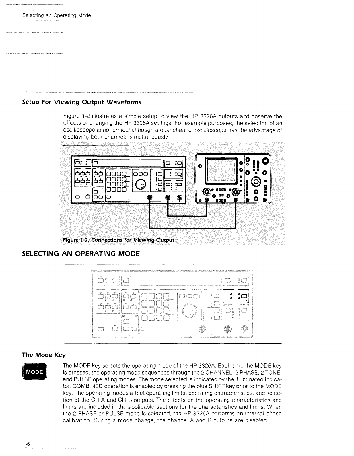
Setup For Viewing Output
Figure 1-2 illustrates a simple setup to view the HP 3326A outputs and observe the
effects of changing the HP 3326A settings. For example purposes, the selection of an
oscilloscope
displaying both channels simultaneously.
Waveforms
is
not critical although a dual channel oscilloscope has the advantage of
SELECTING AN OPERATING MODE
The
Mode
Key
The MODE key selects the operating mode of the HP 332614. Each time the MODE key
2
is pressed, the operating mode sequences through the
and PULSE operating modes, The mode selected is indicated by the illuminated indicator. COMBINED operation is enabled by pressing the blue SHIFT key prior to the MODE
key. The operating modes affect operating limits, operating characteristics, and selec-
B
tion of the CH A and CH
limits are included in the applicable sections for the characteristics and limits. When
the 2 PHASE or PULSE mode is selected, the HP 3326A performs an internal phase
calibration. During a mode change, the channel
outputs. The effects on the operating characteristics and
CHANNEL, 2 PHASE, 2 TONE,
A
and B outputs are disabled.
Page 17
Z
Channel
Mode
STEP
STEP
STEP
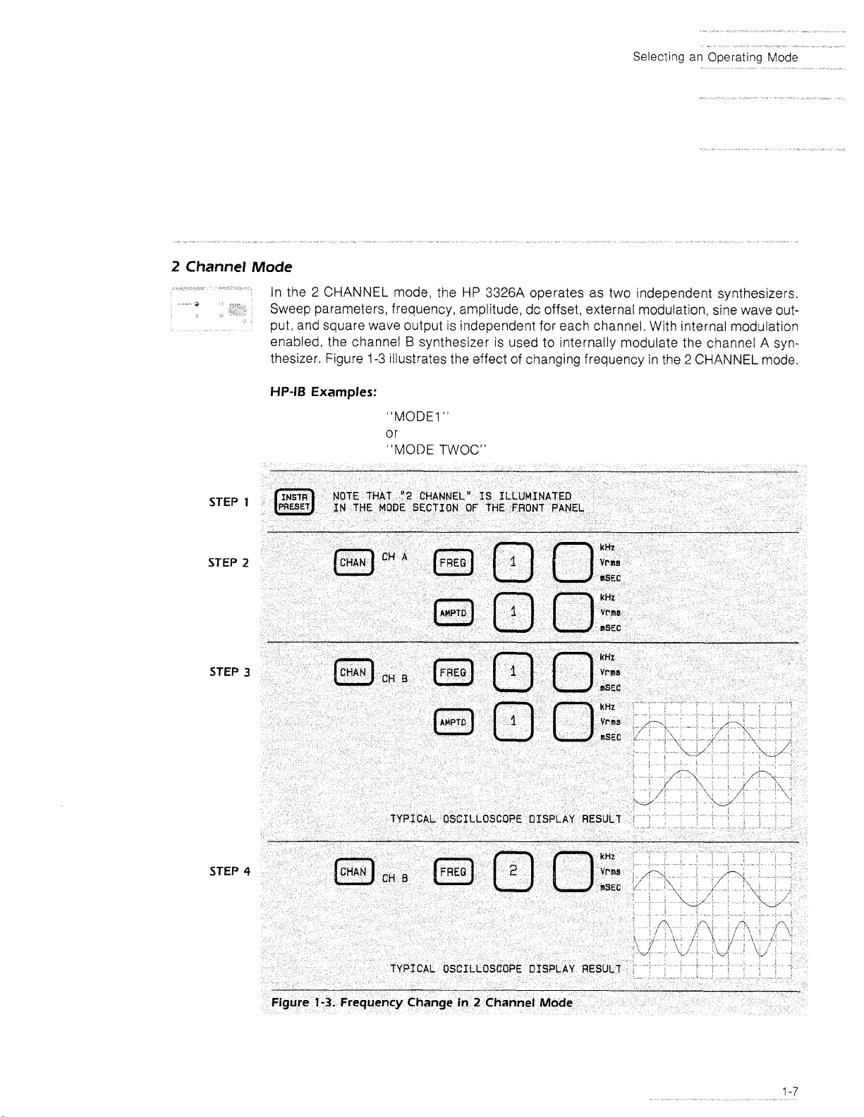
In the 2 CHANNEL
mode, the
HP
3326A
operates as two independent synthesizers.
Sweep parameters, frequency, amplitude, dc offset, external modulation, sine wave output, and square wave output is independent for each channel. With internal modulation
B
enabled, the channel
thesizer. Figure
HP-18
Examples:
1-3
synthesizer is used to internally modulate the channel A syn-
illustrates the effect of changing frequency in the 2 CHANNEL
"MODE1"
or
"MODE TWOC"
1
2
3
mode.
STEP
4
Page 18
-*
Selectmg
7-
2
Phase
-
an
Operating
-"
Mode
Mode
STEP
STEP
STEP
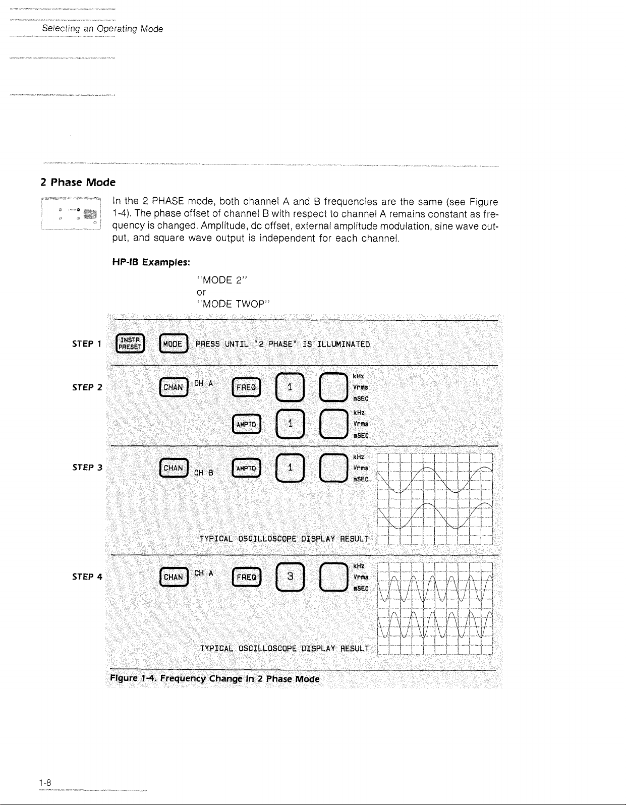
In the 2 PHASE
1-4).
The phase offset of channel B with respect to channel A remains constant as fre-
mode, both channel A and B frequencies are the same (see Figure
quency is changed. Amplitude, dc offset, external amplitude modulation, sine wave output, and square wave output is independent for each channel,
HP-18
Examples:
"MODE
2"
or
"MODE
1
2
3
TWOP"
STEP
4
Page 19
Selectmg an Operating
Mode
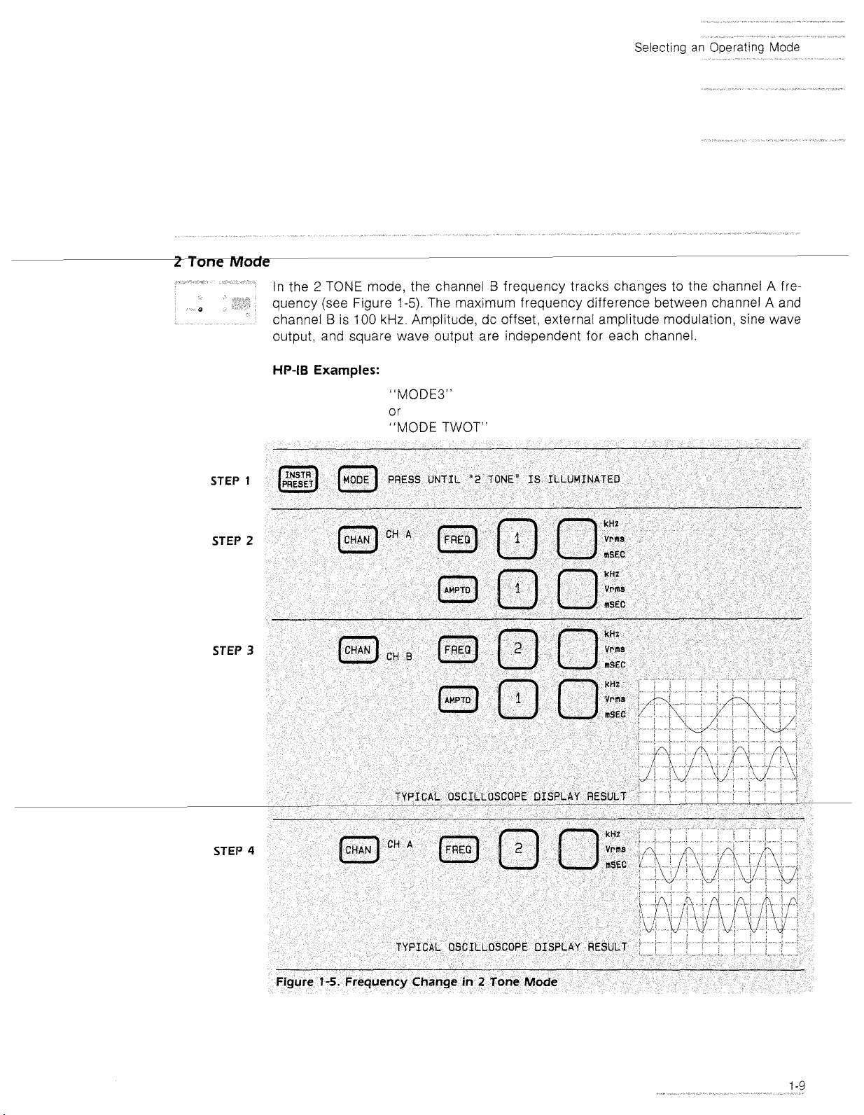
In the 2 TONE mode, the channel B frequency tracks changes to the channel A fre-
1-5).
quency (see Figure
B
channel
is 100 kHz. Amplitude, dc offset, external amplitude modulation, sine wave
The maximum frequency difference between channel A and
output, and square wave output are independent for each channel.
HP-IB
Examples:
"MODE3"
or
"MODE TWOT"
STEP
STEP
STEP
STEP
1
2
3
4
Page 20
ating
Mode
Pulse
,-*-m,s
Mode
---,*
S
STEP
STEP
STEP
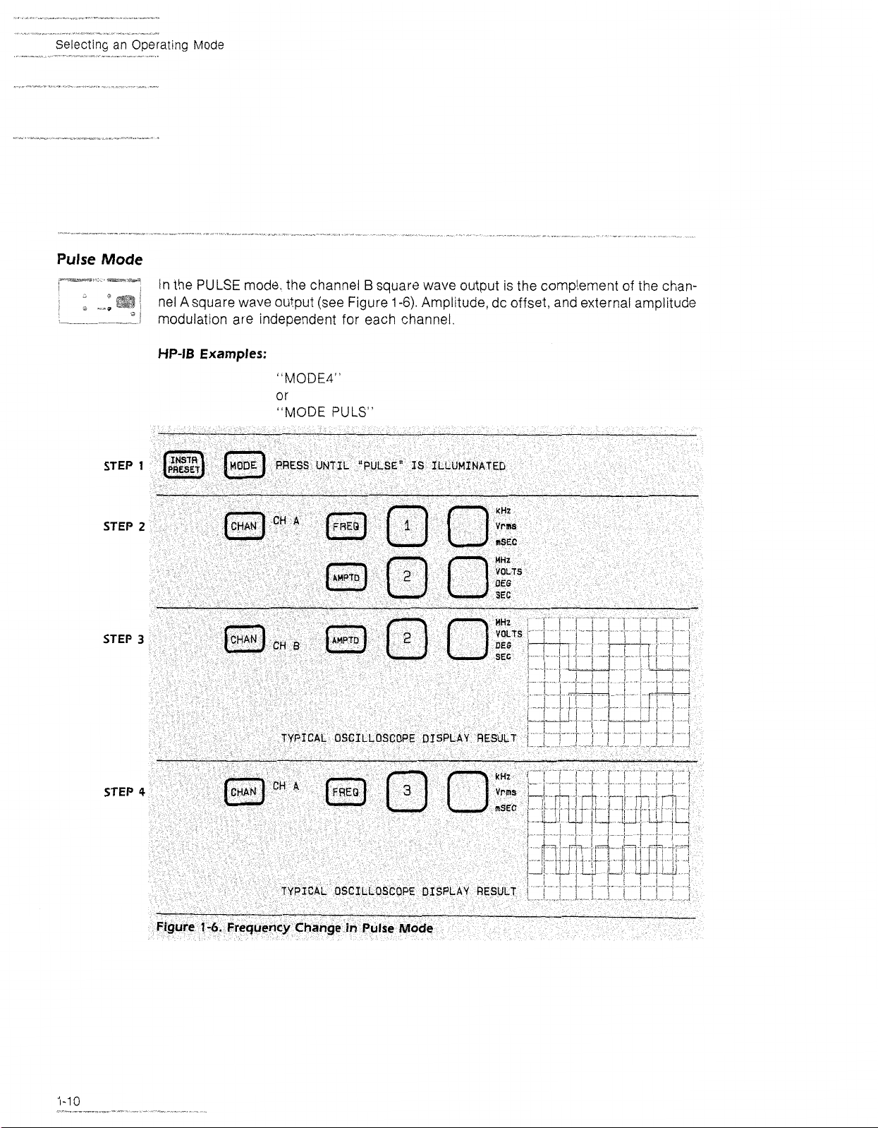
In the
PULSE
nel A square wave output (see Figure
,
mode, the channel B square wave output
1-6).
modulat~on are independent for each channel
HP-IB
Examples:
"MODE$"
or
"MODE
1
2
3
PULS"
IS
the complement of the chan-
Amplitude, dc offset, and external amplitude
STEP
4
Page 21
Combined Operation
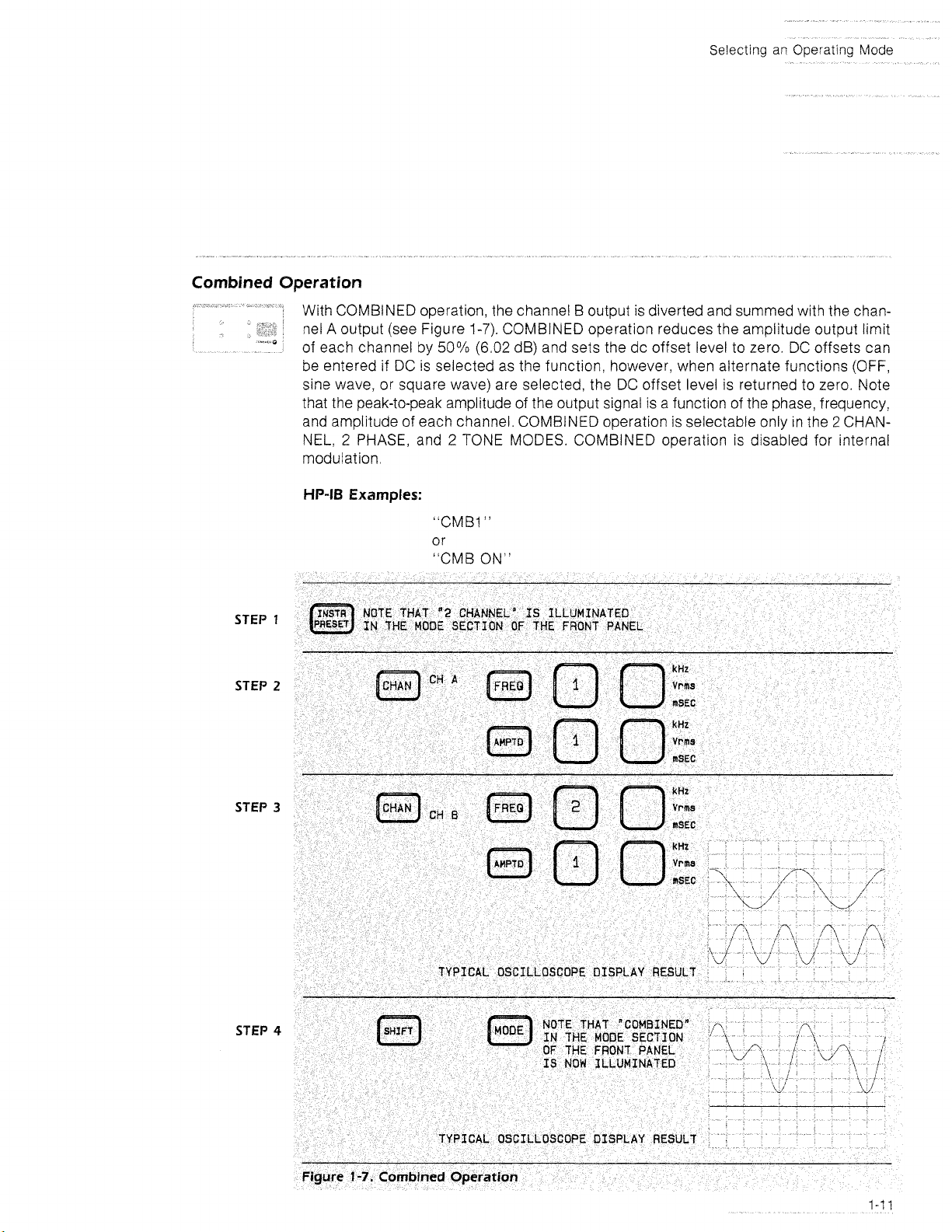
With COMBINED operation, the channel B output is diverted and summed with the channel A output (see Figure
of each channel by
be entered if DC is selected as the function, however, when alternate functions (OFF,
sine wave, or square wave) are selected, the DC offset level is returned to zero. Note
that the peak-to-peak amplitude of the output signal is a function of the phase, frequency!
and amplitude of each channel. COMBINED operation is selectable only in the
NEL,
2
modulation.
HP-IS
Examples:
1-7).
COMBINED operation reduces the amplitude output limit
50%
(6.02 dB) and sets the dc offset level to zero. DC offsets can
2
CHAN-
PHASE, and 2 TONE MODES. COMBINED operation is disabled for internal
STEP
STEP
STEP
"CMBI
"
or
"CMB ON"
1
2
3
STEP
4
Page 22
Selecting the Output Function
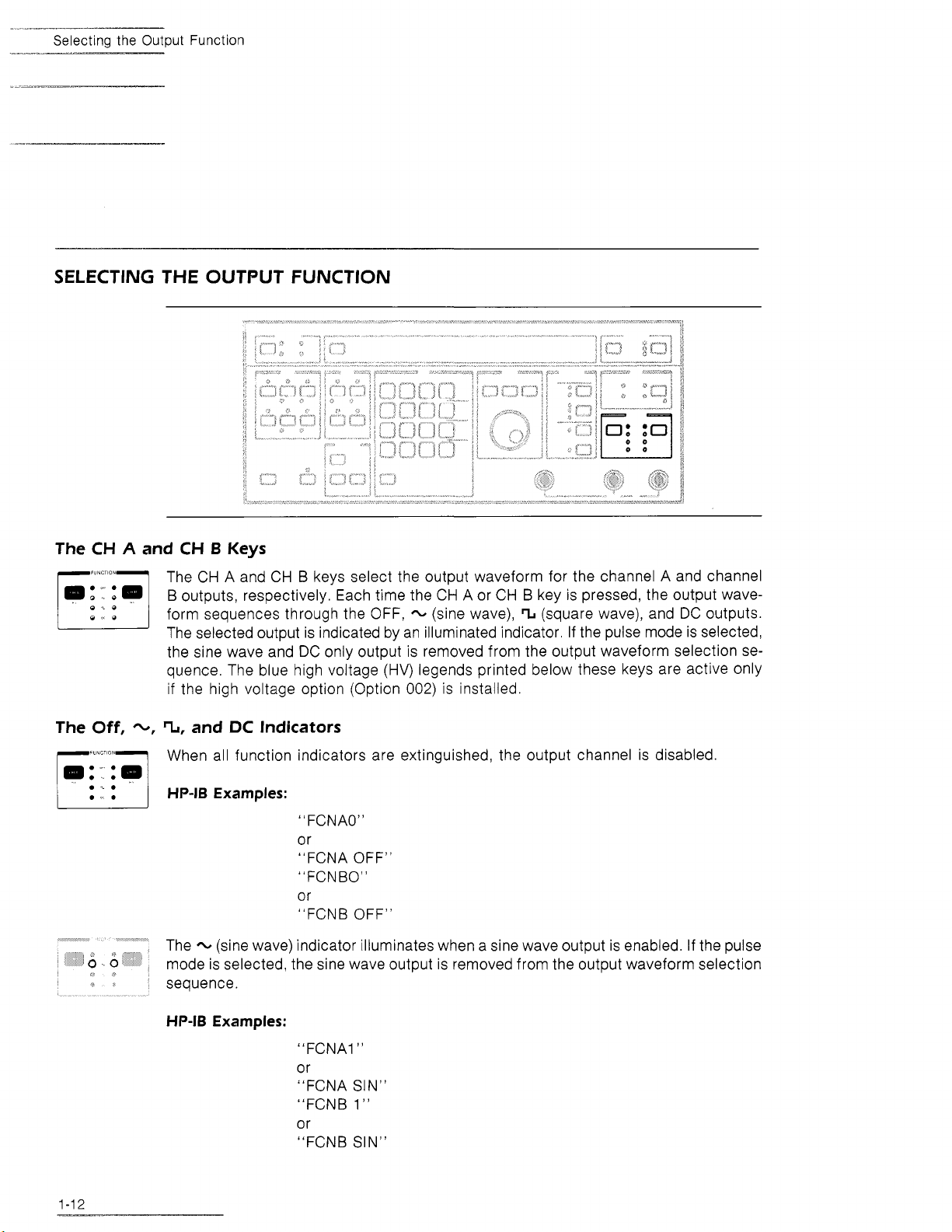
SELECTING THE OUTPUT FUNCTION
The
The
CH
Off,
A
and
CH
B
Keys
The CH A and CH B keys select the output waveform for the channel A and channel
B
outputs, respectively. Each time the CH A or CH B key is pressed, the output waveform sequences through the OFF,
The selected output is indicated by an illuminated indicator. If the pulse mode is selected,
the sine wave and DC only output is removed from the output waveform selection sequence. The blue high voltage (HV) legends printed below these keys are active only
if the high voltage option (Option
-,
TI,
and
DC
Indicators
When all function indicators are extinguished, the output channel is disabled.
HP-16 Examples:
"
FCNAO"
or
"FCNA OFF"
"FCNBO"
or
"FCNB OFF"
-
The
mode is selected, the sine wave output is removed from the output waveform selection
sequence.
(sine wave) indicator illuminates when a sine wave output is enabled. If the pulse
-
(sine wave), % (square wave), and DC outputs.
002)
is installed.
HP-I6 Examples:
"FCNA1"
or
"FCNA SIN"
"FCNB
or
"FCNB SIN"
1"
Page 23
HP-18
Examples:
"
FCNA2"
Selectmg the
Output
Function
or
"FCNA SQR"
"FCNB
2"
or
"FCNB
SQR"
The DC indicator illuminates when a dc only output is enabled. With dc only, the ac
portion of the output is suppressed. The output amplitude for the DC function is controlled by the value entered for the DC OFFSET key.
The
HP-18
Examples:
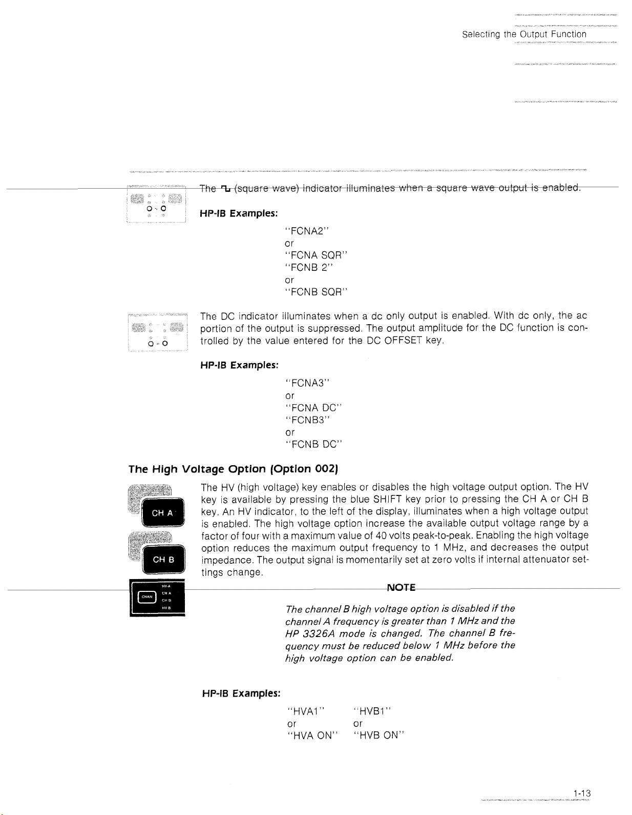
High
Voltage Option (Option
The HV (high voltage) key enables or disables the high voltage output option. The HV
key is available by pressing the blue
key.
An
HV indicator, to the left of the display, illuminates when a high voltage output
is enabled. The high voltage option increase the available output voltage range by a
factor of four with a maximum value of
option reduces the maximum output frequency to
impedance. The output signal is momentarily set at zero volts if internal attenuator set-
tings change.
"FCNAS"
or
"FCNA DC"
"FCNBS"
or
"FCNB
DC"
002)
SHIFT
40
The channel B high voltage option is disabled if the
channel
HP
quency must be reduced below
high voltage option can be enabled.
A
frequency is greater than
3326A
mode is changed. The channel B fre-
key prior to pressing the CH A or CH
volts peak-to-peak. Enabling the high voltage
1
MHz, and decreases the output
WTE
I
MHz
and the
i'
MHz
before the
B
HP-IB
Examples:
"HVAI
"
"HVBI
"
or or
"HVA ON" "HVB ON"
Page 24
Data Entry and Modification
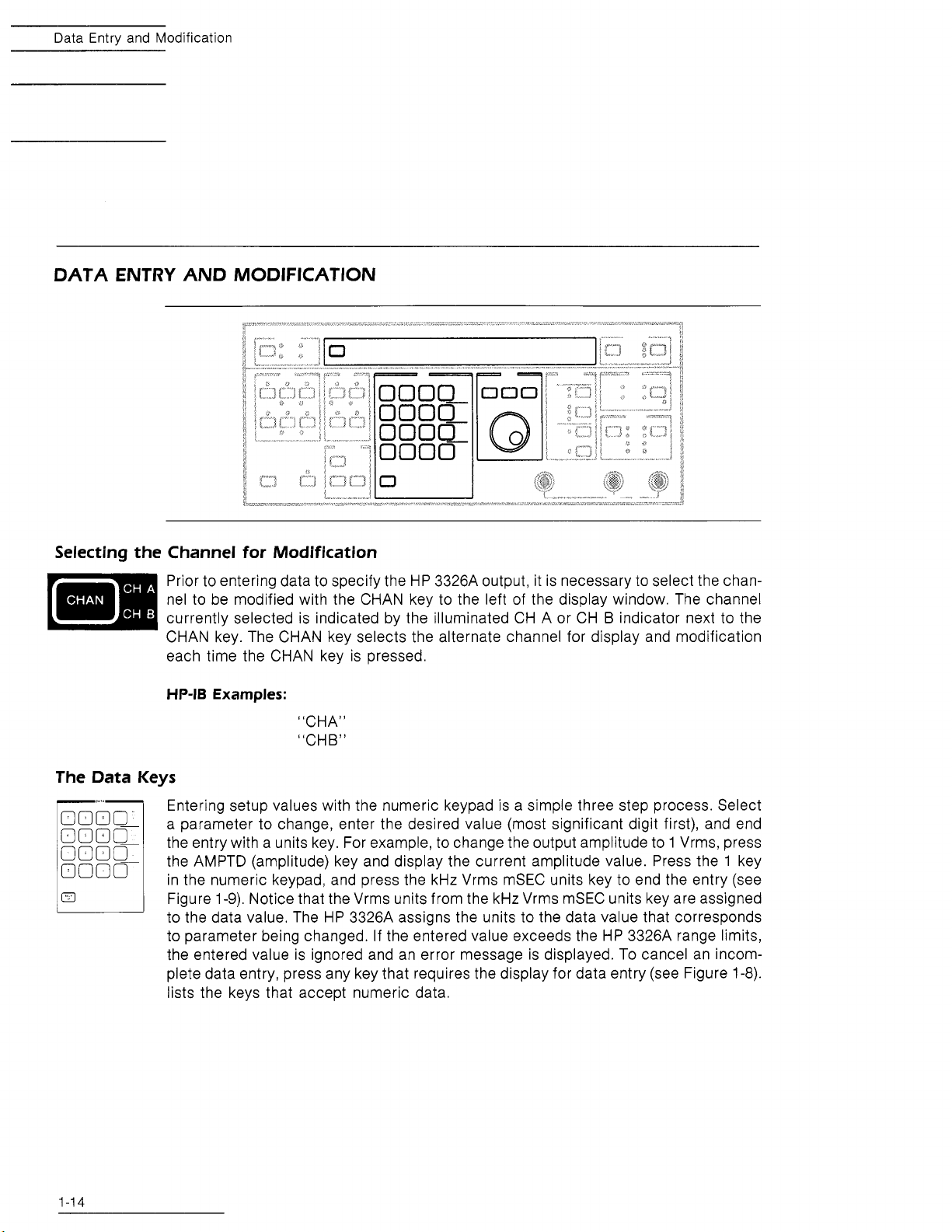
DATA ENTRY AND MODIFICATION
Selecting the Channel for Modification
Prior to entering data to specify the HP 3326A output, it is necessary to select the chan-
nel to be modified with the CHAN key to the left of the display window. The channel
currently selected is indicated by the illuminated CH A or CH
CHAN key. The CHAN key selects the alternate channel for display and modification
each time the CHAN key is pressed.
HP-IB
Examples:
"CHA"
"CHB"
The Data Keys
Entering setup values with the numeric keypad is a simple three step process. Select
a parameter to change, enter the desired value (most significant digit first), and end
the entry with a units key. For example, to change the output amplitude to 1 Vrms, press
the AMPTD (amplitude) key and display the current amplitude value. Press the 1 key
in the numeric keypad, and press the kHz Vrms mSEC units key to end the entry (see
Figure 1-9). Notice that the Vrms units from the kHz Vrms
to the data value. The HP 3326A assigns the units to the data value that corresponds
to parameter being changed. If the entered value exceeds the HP 3326A range limits,
the entered value is ignored and an error message is displayed. To cancel an incom-
plete data entry, press any key that requires the display for data entry (see Figure
lists the keys that accept numeric data.
B
indicator next to the
mSEC units key are assigned
1-8).
Page 25
Data
Entry
and Modif~cation
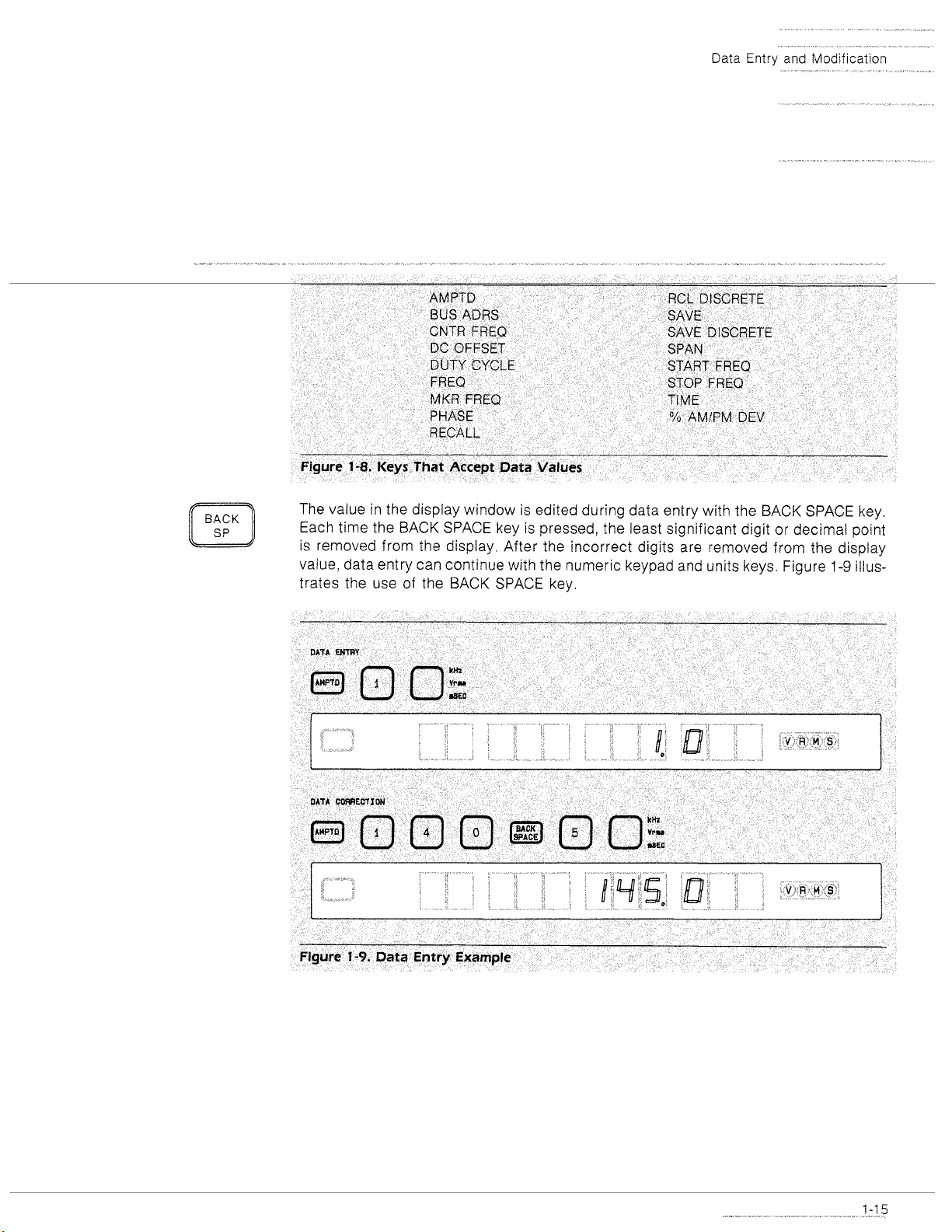
The value in the display window is edited during data entry with the BACK SPACE key.
Each time the BACK SPACE key is pressed, the least significant digit or decimal point
is removed from the display. After the incorrect digits are removed from the display
1-9
value, data entry can continue with the numeric keypad and units keys. Figure
illus-
trates the use of the BACK SPACE key.
L
Figure
1-9.
Data
Entry
Example
I
Page 26
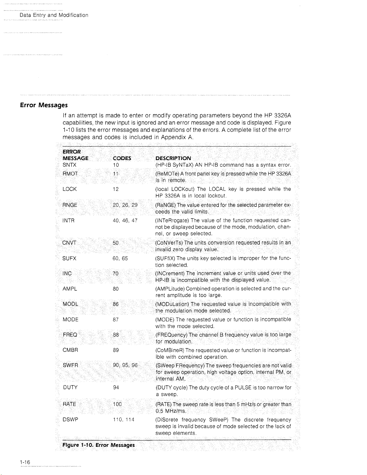
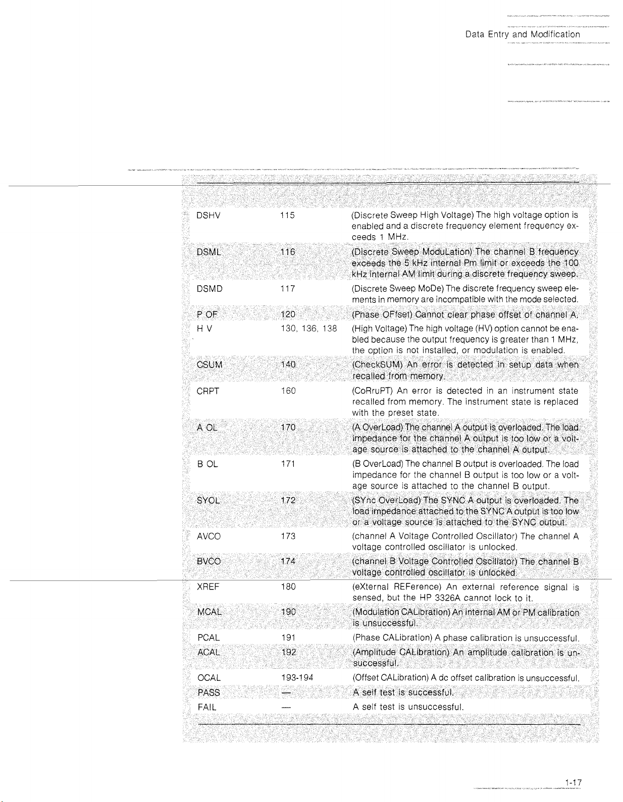
Data Entry and Modification
Error
Messages
If an attempt is made to enter or modify operating parameters beyond the
capabilities, the new input is ignored and an error message and code is displayed. Figure
1-1
messages and codes is included
LOCK 12 (local LOCKout) The LOCAL key is pressed while the
1
NTR 40, 46, 47
SUFX 60, 65
HP
3326A
0
lists the error messages and explanations of the errors. A complete list of the error
in
Appendix A.
IS
rn
HP 3326A
(INTeRrogate) The value of the functron requested cannot be displayed because of the mode, modulation, channel, or sweep selected.
(SUFfiX) The units key selected is improper for the function selected
local lockout
AMPL 80 (AMPLltude) Combined operation is selected and the cur-
rept amolitude is too larae
MODE 87 (MODE) The requested value or function is incompatible
with the mode selected.
CMBR 89 (CoMBineR) The requested value or function is incompat-
ible with combined operation.
DUTY
DSWP
94
110,
114
(DUTY cycle) The duty cycle of a PULSE
a sweeo.
(Discrete frequency SWeeP) The d~screte frequency
sweep
is
invalid because of mode selected or the lack of
sweeD elements.
IS
too narrow
for
Page 27
Data Entry and Modification
--
-*
-
DSHV
DSML
DSMD 117 (Discrete Sweep
P
OF
115
116
123
130, 136,
CRPT
160
(Discrete Sweep High Voltage) The high voltage option is
enabled and a discrete frequency element frequency ex-
1
ceeds
(Discrete Sweep ModuLation) Tee chanqel B frequency
exceeds ihe
kHz internal AV lrmit dcirir,g a discrete frequency sweep.
ments in memory are incom~atible with the mode selected.
(Phase OFfset) Cannot cfear phase offset of channel A.
138 (High Voltage) The high voltage (HV) option cannot be ena-
bled because the output frequency 1s qreater than
(CoRruPT) An error is detected in an instrument state
recalled from memory. The instrument state is replaced
(B
impedance for the channel
MHz.
5
OverLoad) The channel B output
kHz rnternal Pm limit or exceeds tne 100
MoDe) The discrete frequency sweep ele-
1
MHz,
IS
overloaded The load
B
output is too low or a volt-
AVCO 173 (channel A Voltage Controlled Oscillator) The channel A
voltaqe controlled oscrllator is unlocked
sensed, but the HP
MCAL
PCAL 191 (Phase CALibration) A phase calibration is unsuccessful
L
ACA
OCAL
PASS
L
FA1
192
192
193-1 94
-
(Mod~lation CAL~Dration) An internal AM or
is ~nsuccessful.
(Amplitude CALibration) An amplitude call~ration is
successfu!.
(Offset CALibration)
A self test is successfvl.
A self test is unsuccessful.
3326A cannot lock to it
A
dc offset calibration
PM
calibration
is
unsuccessful
un-
Page 28
Data Entry and Mod~f~cation
Viewing Setup Parameters
The current value of a setup parameter is displayed when a front panel key that accepts entries from the keypad (such as the FREQ or AMPTD key) is pressed. Figure
1-8
lists the front panel keys that accept entries from the keypad. Selecting one of these
keys does not alter the current setup values. An error message is displayed if the key
pressed is inactive for the mode selected. Pressing the CHAN key alternates the display between the channel A and B values for the parameter selected.
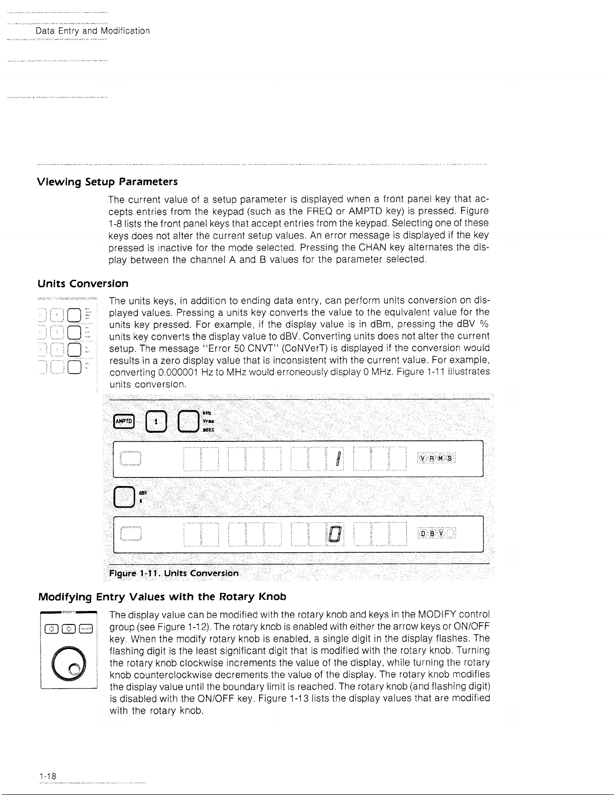
Units Conversion
The units keys, in addition to ending data entry, can perform units conversion on dis-
played values. Pressing a units key converts the value to the equivalent value for the
units key pressed. For example, if the display value is in
units key converts the display value to dBV. Converting units does not alter the current
setup. The message "Error
results in a zero display value that is inconsistent with the current value. For example,
converting 0.000001
units conversion.
Hz
to
dBm, pressing the dBV
50
CNVT" (CoNVerT) is displayed if the conversion would
MHz
would erroneously display 0
MHz,
Figure 1-1 1 illustrates
O/O
Figure
1-1
1.
Units Conversion
Modifying Entry Values with the Rotary Knob
The display value can be modified with the rotary knob and keys in the MODIFY control
group (see Figure
key. When the modify rotary knob is enabled,
flashing digit is the least significant digit that is modified with the rotary knob. Turning
the rotary knob clockwise increments the value of the display, while turning the rotary
l
knob counterclockwise decrements the value of the display. The rotary knob modifies
the display value until the boundary limit is reached. The rotary knob (and flashing digit)
is disabled with the
with the rotary knob.
1-1
2).
The rotary knob is enabled with either the arrow keys or ONIOFF
ONIOFF key. Figure
a
single digit in the display flashes. The
1-1
3
lists the display values that are modified
I
Page 29
Data
Entry
and Mod~fication
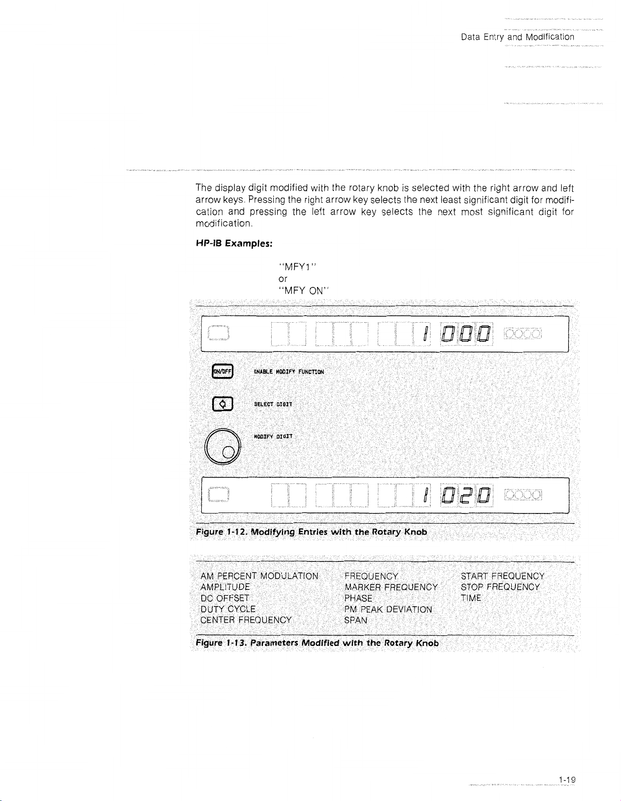
The display digit modified with the rotary knob
is
selected with the right arrow and left
arrow keys. Pressing the right arrow key selects the next least significant digit for modification and pressing the left arrow key selects the next most significant digit for
modification.
HP-IB
Examples:
"MFY1
"
or
"MFY
ON"
Figure
1-12.
Modifying Entries with the Rotary
Knob
Page 30
---
The
Entry
Keys
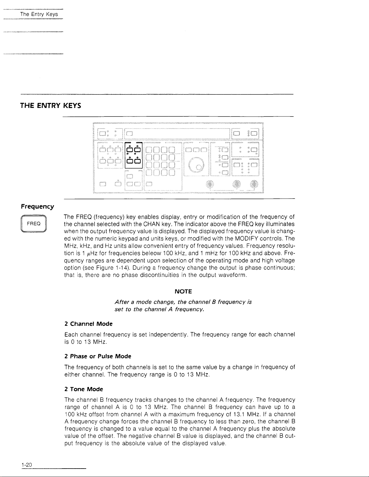
THE ENTRY KEYS
Frequency
The FREQ (frequency) key enables display, entry or modification of the frequency of
the channel selected with the CHAN key. The indicator above the FREQ key illuminates
when the output frequency value is displayed. The displayed frequency value is chang-
ed with the numeric keypad and units keys, or modified with the MODIFY controls. The
MHz, kHz, and Hz units allow convenient entry of frequency values. Frequency resolution is 1
pHz for frequencies beleow 100 kHz, and 1 mHz for 100 kHz and above. Frequency ranges are dependent upon selection of the operating mode and high voltage
option (see Figure 1-14). During a frequency change the output is phase continuous;
that is, there are no phase discontinuities in the output waveform.
NOTE
After a mode change, the channel B frequency
set to the channel A frequency.
2 Channel Mode
is
Each channel frequency is set independently. The frequency range for each channel
0
to 13 MHz.
is
2 Phase or Pulse Mode
The frequency of both channels is set to the same value by a change in frequency of
0
either channel. The frequency range is
to 13 MHz.
2 Tone Mode
The channel B frequency tracks changes to the channel A frequency. The frequency
0
range of channel A is
100 kHz offset from channel
A frequency change forces the channel
to 13 MHz. The channel B frequency can have up to a
A
with a maximum frequency of 13.1 MHz. If a channel
B
frequency to less than zero, the channel
B
frequency is changed to a value equal to the channel A frequency plus the absolute
B
value of the offset. The negative channel
value is displayed, and the channel B out-
put frequency is the absolute value of the displayed value.
Page 31

The
Entry
Keys
The frequency range of channel A is 0 to
is 0 to
Internal Amplitude Modulation
The frequency range of channel
is
HV Option
0
to
5
kHz.
I00 kHz.
A is
0
to
13
13
MHz.
The frequency range of channel
MHz.
The frequency range of channel
With the high voltage option enabled, the frequency output is 0 to
2
TONE
mode, the maximum channel B frequency is
HP-I6 Example:
NOTE
After a mode change, the channel B frequency is
set to the channel
quency is set to greater than
B
high voltage option is disabled, To enable the high
voltage option, reduce the channel B frequency to
I
below
MHz.
A
frequency. If the channel 5 fre-
I
MHz,
1
.I
MHz.
the channel
"FR7.500003MHZ"
1
MHz.
B
B
In the
Page 32

The Entry Keys
Amplitude
The AMPTD (amplitude) key enables display, entry, or modification of the amplitude
of the channel selected with the CHAN key. The indicator above the AMPTD key illuminates when an amplitude value is displayed. The displayed amplitude value is
changed with the numeric keypad and units keys, or modified with the MODIFY controls. The VOLTS, Vrms,
The amplitude range without dc offset is from
(4
mV peak-to-peak to 40 V peak-to-peak with high voltage enabled). The amplitude range
dBm, and dBV units allow convenient entry of amplitude values.
1
mV peak-to-peak to
10
V peak-to-peak
is dependent upon selection of COMBINED operation, internal modulation, dc offset,
and high voltage option (see Figure
1-1
5).
The output signal is momentarily set at zero
volts if internal attenuator settings change.
Internal Modulation
With internal modulation, the channel B amplitude is controlled by the % AMlPM DEV
key. Internal modulation uses the channel B output internally and a signal is unavailable at the CH B connector.
High
Voltage Option
With the high voltage option, the upper amplitude limit is increased to 40 volts peak-to-
4
peak and the lower amplitude limit is increased to
output needs to be enabled prior to entering voltage values greater than
Combined
mV peak-to-peak. The high voltage
10
volts.
For COMBINED operation, the output of channel B is diverted and summed with the
(6.02
channel A output. The amplitude limit of each channel is reduced by 50%
The upper amplitude limit for COMBINED operation is
rt
5
volts
(2
20 volts with the
dB).
high voltage option enabled). Note that the output amplitude level is dependent upon
phase, frequency, and amplitude values.
Page 33

DC
The Entry Keys
Offset
The limit for an ac output with a dc offset is
1-1
6
high voltage option enabled). Figure
HP-IB
Example
"AM1
.125VOH
illustrates dc offset versus amplitude.
t
5
volts peak
(k
20
volts peak with the
Page 34

*
The
DC
OFFSET
c3
-"
Entry
Keys
Offset
The DC OFFSET key enables display, entry, or modification of the dc offset of the channel
1-17).
selected with the CHAN key (see Figure
key illuminates when a dc offset value is displayed. The displayed dc offset value is
changed with the numeric keypad and VOLTS units key, or modified with the MODIFY
controls. The maximum dc offset range is
option enabled). The dc offset range is dependent upon amplitude, and selection of combined operation, internal modulation, and high voltage option. Figure
HP
imum output of the
nal attenuator settings change.
3326A.
The output signal is momentarily set at zero volts if inter-
The indicator above the DC OFFSET
+
5
volts
(-+
20
volts with the high voltage
1-1
5
lists the max-
STEP
STEP
1
2
Page 35

The Entry Keys
AC
with
DC
Offset
The maximum dc offset is a function of the selected ac amplitude. The maximum am-
+
5
plitude for ac plus dc is
versus amplitude (with combined operation, internal modulation, and high voltage option disabled) is illustrated in Figure 1-16. The maximum ac and dc outputs and maxi-
mum dc offsets for the
volts peak
HP
3326A are:
(+
20 with the high voltage option). DC offset
AC AMPLITUDE
1.0 to 10 Vpp
0.1
to 1.0 Vpp
10 to 100 mVpp
1 to 10 mvpp 55 mV t4.5 mV
DC
Only
With the output FUNCTION set to DC, the output level is controlled by DC OFFSET entries. The maximum dc output is
Cornblned
For COMBINED operation with a sine wave, square wave, or OFF output FUNCTION
selected, the dc offset is set to zero.
High Voltage Option
With the high voltage option enabled, the dc offset range is + 20 volts (ac + dc peak
value or dc only). DC offset with the high voltage option is independent of the ac amplitude except that the combination of ac plus dc cannot exceed
Internal Modulation
With internal modulation, the channel B dc offset is disabled.
HP-IB Example
MAXIMUM AC
+
5.0 V k4.5 V
+
0.5 V
+
50 mV
+
5
volts peak
+
DC MAXIMUM DC OFFSET
t
0.45 V
5
45 mV
(+
20 with the high voltage option).
+
20 volts.
"OF3VO"
Page 36

Phase
STEP
STEP
STEP
The PHASE key enables display, entry, or modification of the phase of the channel
selected with the CHAN key. The indicator above the PHASE key illuminates when a
phase value is displayed. The displayed phase value is changed with the numeric keypad and DEG
display range is
degrees entered through the keypad are accepted and the value is displayed modulo
720. The effect of the phase offset is dependent upon selection of the operating mode.
Figure
1
2
3
(DEGrees) units key, or modified with the MODIFY controls. The phase
a
720 degrees with a resolution of 0.01 degrees. Phase values of
1-18
illustrates the effect of changing phase.
i:
1440
2
Channel
Changing phase in the 2 CHANNEL mode changes the phase of a channel with respect
to the initial waveform. The phase of channel A and
2
Phase Mode
Without an external phase reference, a change in the phase of channel A is made with
respect to the initial channel
in the phase of channel A is made with respect to the external reference. Channel
uses channel A as the phase reference, and a change to the channel B phase is made
with respect to the current channel A waveform.
Mode
B
are independent.
A
waveform. With an external phase reference, a change
B
Page 37

The
Entry
Keys
2
Tone Mode
Changing phase in the 2 TONE mode changes the phase of a channel with respect to
B
the initial waveform. The phase of channel A and
are independent.
Pulse Mode
A change in the phase of channel A is made with respect to the initial channel A wave-
B
form. The channel
to display the channel
output is the complement of the channel A output. An attempt
B
phase results in the display of the "Error
47
INTR" (INTeR-
rogate) message.
Asgn
Clr
C$
Zero
C$
Offset
The ASGN ZERO 4 (ASSIGN ZERO phase) key asslgns zero to the phase offset between
channel A and
ing the phase of the output waveforms The ASGN ZERO
the blue SHIFT key prior to the PHASE key
phase value
summed modulo
assignments
The stored phase offset value
offset) indicator illuminates when a phase offset value
B
(or between channel A and an external phase reference) wlthout chang-
4
key
IS
selected by pressmg
If
channel A
IS
changed to zero If channel B is selected, the phase offset value
720
and stored in an internal phase offset regrster
of zero phase sums the
displayed
IS
recalled with the
phase value into the phase offset register
CLR
IS
selected, the channel A
Subsequent
OFS key The OFS (phase
IS
stored
IS
HP-IS Example
"ZPH"
The CLR p OFS (CLeaR phase OFfSet) key restores the channel B phase offset value
to the display without chang~ng the phase of the output waveforms. If the current channel
B
phase value is nonzero, the phase offset is summed to the phase value modulo
720
The CLR 4 OFS key is selected by pressing the blue SHIFT key prior to the
DC
OFFSET key The CLR 4 OFS key extinguishes the 4 OFS indicator Pressing the CLR
4
OFS key with channel A selected displays the message "Error 120 P OF" (Phase
OFfset).
HP-IB Example
"COF"
Page 38

The
Duty
Entrv
Cycle
iL:
(~~
,~
Keys
(Pulse
Width)
The DUTY CYCLE key enables display, entry, or modification of the duty cycle of the
A
pulse mode channel
waveform. The DUTY CYCLE key is selected by pressing the
blue SHIFT key prior to the FREQ key. The DUTY CYCLE indicator illuminates when
the duty cycle value is displayed. After selection of the DUTY CYCLE key, the duty cycle
value is changed with the numeric keypad and
controls. The duty cycle range is from 1
width of 20 nanoseconds. The resolution of the duty cycle is 0.01
O/O
units key, or modified with the MODIFY
O/O
to 99% of the period with a minimum pulse
O/O.
The duty cycle
remains constant for changes in frequency provided the pulse width is greater than
20 nanoseconds. Figure 1-19 illustrates the effect on changes in duty cycle.
HP-IS
Example
STEP
STEP
STEP
1
2
3
Page 39

Linear Frequency Sweep
LINEAR FREQUENCY
Linear sweeps are phase continuous over the full frequency range; that is, there are
no phase discontinuities in the swept output waveform. Single or continuous (see Figure
-20),
and ramp or triangle (see Figure 1-21) linear sweeps are selectable. Linear sweep
1
parameters are entered with the START FREQ (START FREQuency), STOP FREQ (STOP
FREQuency), CNTR FREQ (CeNTeR FREQuency), SPAN, TIME, AND MKR-CF keys.
The MKR FREQ (MarKeR FREQuency) key allows the rear panel TTL level MARKER
OUT (MARKER OUTput) signal to be specified.
SWEEP
Page 40

Single Sweep
Sweep
The SINGLE key initiates a single linear sweep. The indicator above the SINGLE key
illuminates when a single sweep is in progress. With a ramp sweep selected (i.e. TRIANGLE indicator extinguished), the SINGLE key initiates a sweep from the start frequency to the stop frequency over the specified sweep time. Upon reaching the stop
frequency, the frequency is quickly changed to the start frequency. With a TRIANGLE
sweep selected, the SINGLE key initiates a sweep from the start frequency to the stop
frequency over the specified sweep time. The stop frequency is maintained until the
SINGLE key is pressed. Pressing the SINGLE key initiates another sweep from the stop
frequency to the start frequency.
HP-IB Example:
Continuous Sweep
The CONT (CONTinuous) key initiates a continuous linear sweep. The indicator above
the CONT key illuminates when a continuous sweep is in progress. With a ramp sweep
selected (i.e. TRIANGLE indicator extinguished), the CONT key initiates
sweep from the start frequency to the stop frequency over the specified sweep time.
Upon reaching the stop frequency, the frequency is quickly changed to the start fre-
quency in preparation for the next sweep. With a TRIANGLE sweep selected, the CONT
key initiates a repetitive sweep from the start frequency to the stop frequency and back
to the start frequency. Each sweep (from either the start frequency to stop frequency,
or from stop frequency to start frequency) is over the specified sweep time.
HP-16 Example:
"SS"
"SC"
a.
repetitive
Page 41

Page 42

Linear Frequency Sweep
Start Frequency
START
The START FREQ (START FREQuency) key enables display, entry, or modification of
the linear sweep start frequency of the channel selected with the CHAN key. The indicator above the START FREQ key illuminates when a start frequency value is displayed.
The displayed frequency value is changed with the numeric keypad and units keys, or
modified with the MODIFY controls. The MHz, kHz, and Hz units allow convenient entry
of frequency values. Frequency resolution is
1
pHz for frequencies below 100 kHz and
1 mHz for frequencies above 100 kHz. Start frequency values may be greater than the
stop frequency values for a sweep from a high frequency to a low frequency.
2
Channel Mode
Each channel start frequency is set independently. The frequency range of each chan-
nel is 0 to 13 MHz.
2
Phase or Pulse Mode
The start frequency of both channels is set to the same value by a change in start fre-
quency of either channel. The frequency range is 0 to 13 MHz.
2
Tone Mode
The channel B start frequency tracks changes to the channel A start frequency. The
A
channel
have up to a 100 kHz offset from channel
If
a channel A frequency change forces the channel B frequency to less than zero, the
channel
start frequency range is 0 to 13 MHz. The channel B start frequency can
A
with a maximum frequency of 13.1 MHz.
B
frequency is displayed as a negative value while the channel B output fre-
quency is the absolute value of the displayed value.
Internal Phase Modulation
The start frequency range of channel A is 0 to 13 MHz. The start frequency range of
channel
Internal Amplitude Modulation
B
is 0 to 5 kHz.
The start frequency range of channel A is 0 to 13 MHz. The start frequency range of
channel
HV Option
B
is 0 to 100 kHz.
With the high voltage option enabled, the start frequency range is 0 to 1 MHz. In the
2 TONE mode, the maximum channel
HP-16 Example:
B
start frequency is 1.1 MHz.
"ST1.512525KHZ"
Page 43

Linear Frequency
Sweep
The STOP FREQ (STOP FREQuency) key enables display, entry, or modification of the
linear sweep stop frequency of the channel selected with the CHAN key. The indicator
above the STOP FREQ key illuminates when
a
stop frequency value is displayed. The
displayed frequency value is changed with the numeric keypad and units keys, or modified with the MODIFY controls. The MHz, kHz, and Hz units allow convenient entry of
frequency values. Frequency resolution is 1 pHz for frequencies below 100 kHz and
1 mHz for frequencies above 100 kHz.
2
Channel Mode
Each channel stop frequency is set independently. The frequency range of each channel is 0 to 13 MHz.
2
Phase or Pulse Mode
The stop frequency of both channels is set to the same value by a change in stop fre-
quency of either channel. The frequency range is 0 to 13 MHz.
2
Tone Mode
The channel B stop frequency tracks changes to the channel A stop frequency. The
stop frequency range of channel A is 0 to 13 MHz. The channel
B
stop frequency can
have up to a 100 kHz offset from channel A, wit'h a maximum frequency of 13.1 MHz.
B
If a channel A frequency change forces the channel
B
channel
frequency is changed to a value equal to the channel A frequency plus the
frequency to less than zero, the
absolute value of the offset.
Internal Phase Modulation
The stop frequency range of channel A is 0 to 13 MHz. The stop frequency range of
channel
Internal Amplitude Modulation
B
is 0 to 5 kHz.
The stop frequency range of channel A is 0 to 13 MHz. The stop frequency range of
channel
HV
B
Option
is 0 to 100 kHz.
With the high voltage option enabled, the stop frequency range is 0 to 1 MHz. In the
2
TONE mode, the maximum channel B frequency is 1.1 MHz.
HP-16 Example:
"SP7.512525KHZ"
Page 44

Linear
Time
Frequency
Sweep
The TlME key enables display, entry, or modification of the linear sweep time for both
channels. The indicator above the TIME key illuminates when a time value is displayed.
The displayed time value is changed with the numeric keypad and units keys, or modi-
fied with the MODIFY controls. The SEC and mSEC units keys end entry of numeric
1000
values. The time range is 5 milliseconds to
seconds, with a resolution of 1 mil-
lisecond.
HP-IB Example:
"ST1 M25MS"
Marker Frequency
The MKR FREQ (MarKeR FREQuency) key enables display, entry, or modification of
the marker frequency of the channel selected with the CHAN key. The indicator above
the MKR FREQ key illuminates when the marker frequency value is displayed. The dis-
played frequency value is changed with the numeric keypad and units keys, or modified with the MODIFY controls. The MHz, kHz, and Hz units allow convenient entry of
frequency values. Frequency resolution is
1 mHz for frequencies above 100 kHz. Only one marker is available.
For a marker signal to be generated, the MKR FREQ must be within 3 milliseconds of
the start or stop frequency. The following equation may be used to determine the approximate marker offset from the start or stop frequency:
I
pHz for frequencies below 100 kHz and
NOTE
When different start or stop frequencies are entered
for each channel, selecting alternate channels can
have the apparent effect of changing the marker
frequency, Although the marker occurs at the same
time, each channel may have a unique frequency
at that time.
x
MARKER OFFSET
1
0.003
SPAN
SWEEP TlME
The marker value is accepted and the message "Error 24 RNGE" is displayed if the
marker value is outside the sweep frequency span. The Z-BLANK output is coincident
with the start and stop frequencies and may be used for the marker of these frequencies.
HP-1B Example:
Page 45

Triangle
Linear Frequency Sweep
The TRIANGLE key selects either a triangle or ramp sweep. The TRIANGLE key is
selected by pressing the blue SHIFT key prior to the MKR FREQ key. The TRIANGLE
indicator is illuminated when a triangle sweep is selected, and extinguished when a
ramp sweep is selected.
HP-If3
Examples:
"SMI
"
"SM2"
or or
"SM RAMP" "SM TRGL"
STEP
STEP
STEP
1
Z
3
STEP
4
Page 46

L~near
Frequency
Sweep
Reset
Span
Sweep
.
,
B
,,
The RESET SWP (RESET SWeeP) key resets the sweep circuits to the start of the sweep.
During reset, the HP 3326A also checks the sweep limits.
HP-I6 Example:
"SRE"
The SPAN key enables display, entry, or modification of the total linear sweep frequency
span of the channel selected with the CHAN key. The SPAN key is available by pressing the blue SHIFT key prior to pressing the STOP FREQ (STOP FREQuency) key. The
SPAN key, with the CNTR FREQ (CeNTeR FREQuency) key, provides an alternate entry
for the frequency sweep start and stop values. The SPAN indicator illuminates when
SPAN is selected and the SPAN value is displayed. The displayed frequency span value
is changed with the numeric keypad and units keys, or modified with the MODIFY controls. The MHz, kHz, and Hz units allow convenient entry of frequency values. Frequency
resolution is 1
pHz for frequencies below 100 kHz and 1 mHz for frequencies above
100 kHz.
NOTE
Frequency spans must be consistent with the operating limits and the value entered for the center frequenc y. Excessive frequency spans are s ymmetrica//y reduced around the current center frequency
to bring the start or stop frequencies within limits.
2
Channel Mode
The frequency span of each channel is set independently. The frequency range of each
channel is 0 to 13 MHz,
2
Phase
or
Pulse Mode
The frequency span of both channels is set to the same value by a change in the fre-
0
quency span of either channel. The frequency range is
2
Tone Mode
to 13 MHz.
The frequency span range for channel A is 0 to 13 MHz. Changing the channel A frequency span also changes the channel
current start and stop frequency offsets. The channel
B
center frequency and span to maintain the
B
frequency span may be set
so that the start and stop frequencies are within 100 kHz of the channel A start and
B
stop frequencies. If a channel A frequency change forces the channel
less than zero, the channel
B
channel
frequency.
B
output frequency is changed to the absolute value of the
frequency to
Page 47

HV Option
Linear Frequency
NOTE
The difference (offset) between the channelA and
B
frequencies will normally change during a sweep
to maintain the offsets entered for the sweep start
and stop frequencies. If a constant offset is desired,
there must be a constant offset between the start
and stop frequency values for channel
A
and
5.
Sweep
With the high voltage option enabled, the maximum frequency span is 1 MHz. In the
2
TONE
mode, the maximum channel B frequency span is 1.1 MHz.
HP-IB Example:
Center Frequency
The CNTR FREQ (CeNTeR FREQuency) key enables display, entry, or modification of
the linear sweep center frequency of the channel selected with the CHAN key. The
CNTR FREQ key is available by pressing the blue SHIFT key prior to the START FREQ
key. The CNTR FREQ key, along with the SPAN key, provides an alternate entry of the
frequency sweep start and stop values.
The displayed frequency value is changed with the numeric keypad and units keys, or
modified with the MODIFY controls. The MHz, kHz, and Hz units allow convenient entry
of frequency values. The frequency resolution is 1
and 1 mHz for frequencies above 100 kHz. If the center frequency causes the sweep
start or stop frequency to exceed the HP
Z
Channel Mode
The center frequency of each channel is set independently. The frequency range of
each channel is 0 to 13 MHz.
2
Phase or Pulse
The center frequency of both channels is set to the same value by a change in center
frequency of either channel. The frequency range is 0 to 13 MHz.
pHz for frequencies below 100 kHz
3326A limits, the frequency span is reduced,
Mo
2
Tone Mode
The channel A center frequency has the range of 0 to 13 MHz. The start and stop frequencies of channel
maintain the current offset. The channel
offset from channel
100 kHz of the channel
HP-IS Example:
B
tracks changes to the channel A start and stop frequencies to
B
center frequency can have up to a 100 kHz
A
providing the channel B start and stop frequencies are within
A
start and stop frequencies.
"CF5.512525KHZ"
Page 48

L~near Frequency Sweep
Marker to Center Frequency
The MKR
quency set for the marker, The MKR
key prior to the
quency limits, the frequency band is reduced.
2
Channel Mode
The center frequency of each channel is set independently. The frequency range of
each channel is
2
Phase or Pulse Mode
The center frequency of both channels is set to the same value by a change in the
center frequency of either channel. The frequency range is 0 to 13 MHz.
2
Tone Mode
The channel A center frequency has the range of 0 to 13 MHz. The start and stop frequencies of channel
maintain the current offset. The channel
offset from channel
100 kHz of the channel
HP-IB
--
CF (MarKeR to Center Frequency) key centers the sweep band on the fre-
-
CF key is selected by pressing the blue SHIFT
CONT
Example:
key. If either the sweep start or stop frequency exceeds the fre-
0
to 13 MHz.
B
tracks changes to the channel A start and stop frequencies to
B
center frequency can have up to a 100 kHz
A
providing the channel B start and stop frequencies are within
A
start and stop frequencies.
"CFM"
Page 49

DISCRETE FREQUENCY SWEEP
D~screte Frequency Swee~
Discrete
Recall
Discrete
During a discrete frequency sweep, the HP 3326A sequences through the discrete frequency sweep elements (channel
volatile memory with the SAVE DISCRETE key (see Figure 1-22). Discrete frequency
sweep element frequencies are entered with the FREQ
times are entered with the TlME key. The HP 3326A always sequences through the
discrete frequency sweep elements from element
SINGLE sweep selected, the HP 3326A sequences through the elements each time
the SINGLE key is pressed. With CONT sweep selected, the HP
through the elements continuously. The message "Error 11
SWeeP) is displayed if no discrete frequency sweep elements are stored in memory.
Selecting TRIANGLE for a discrete frequency sweep cancels the discrete frequency
sweep and selects a linear sweep.
The DISCRETE key enables and disables discrete frequency sweeps. The DISCRETE
key is available by pressing the blue SHIFT key prior
DISCRETE indicator illuminates when discrete frequency sweeps are enabled.
HP-IB
Examples:
"SM3"
0
r
"SM DSCR"
A
and B frequencies, and dwell time) stored in non-
(FREQuency) key, and dwell
00
to the last element entered. With
3326A sequences
0
DSWP" (Discrete frequency
to
pressing the TlME key. The
-
The RCL DISCRETE (ReCaLI DISCRETE) key followed by a discrete element number
A
replaces the channel
for a d~screte frequency sweep element The RCL DISCRETE key 1s avadable by pressing the blue SHIFT key prlor to pressing the RECALL key. Val~d discrete elements numbers range from
d~splays the message "Error
HP-IB
Example:
and B frequency values and time values with the values stored
00
to 62. Recalling a null discrete frequency sweep element number
20
RNGE
"
Page 50

Discrete Frequency
Save
Discrete
The SAVE DISCRETE key followed by a dlscrete frequency sweep element number stores
the current channel A and
memory The SAVE DISCRETE key is available by pressing the blue SHIFT key prlor
to pressing the SAVE key Vahd discrete frequency sweep element numbers range from
00
bers must start with
be recalled, ed~ted, and replaced in any order Stormg a discrete frequency sweep ele-
ment wlth a
sage "Error 23 RNGE" (RaNGE) The message "Error
SWeeP) is displayed ~f a d~screte frequency element
changed.
Sweep
B
frequency values and dwell t~me value In nonvolatile
to 62. When initially entering discrete frequency sweep elements, the element num-
00
and be sequential Exlst~ng discrete frequency elements may
nonsequential
number, or using a number greater than 62 displays the mes-
11
7
DSWP" (Discrete frequency
IS
entered after the mode
IS
Discrete frequency sweep element storage uses the same nonvolatile memory as the
SAVE key stores. Discrete sweep frequency storage memory is assigned by the
3326A. Discrete frequency sweep elements are stored in the following memory
HP
registers:
DISCRETE
FREQUENCY
ELEMENT
NUMBER
00 - 06
-
13
07
-
20
14
21
-
27
28
-
34
-
41
35
42
-
48
49
-
55
56 - 62
MEMORY
REGISTER
9
8
7
6
5
4
3
2
1
Saving an operating state in a memory register that interrupts the contiguous memory
used to save discrete frequency sweep elements displays the "Error 23 RNGE" (RaNGE)
message. Saving an operating state in the lowest memory register occupied by dis-
crete frequency sweep elements reclaims that memory register for operating state
storage.
HP-IS
Example:
Page 51

Single Sweep
The SINGLE key initiates a single discrete frequency sweep. The indicator above the
SINGLE key illuminates when a single sweep is in progress. The SINGLE key initiates
a sweep from the discrete frequency sweep element 00 to the last entered element.
During a sweep, the SINGLE key causes the HP
crete frequency sweep element to the next discrete frequency sweep element.
HP-IB Example:
Continuous Sweep
"SS"
Discrete Frequency
3326A to step from the current dis-
Sweep
Clear Discrete
Time
The CONT (continuous) key initiates a continuous discrete frequency sweep. The indi-
a
cator above the CONT key illuminates when
HP-IB Example:
"SC"
The CLR DISCRETE (CLeaR DISCRETE) key replaces the discrete frequency sweep
elements stored in nonvolatile memory with the preset operating state. The CLR
DISCRETE key is available by pressing the blue
PRESET key,
HP-IB Example:
"DRST"
The TIME key enables display, entry, or modification of the discrete frequency sweep
element dwell time for both channels. After selection of the TIME key, the time value
is changed with the numeric keypad and units
trols. The SEC and
from
5
milliseconds to 1000 seconds with a resolution of 1 millisecond.
HP-IB Example:
mSEC units keys end entry of numeric values. The time range is
continuous sweep is in progress.
SHIFT key prior to the green INSTR
keys! or modified with the MODIFY con-
Reset Sweep
"STIM25MS"
The RESET SWP (reset sweep) key resets the sweep circuits to the start of the sweep.
For triggered operation, manually resetting the sweep circuits before the trigger
minimizes the delay between the trigger and start of sweep.
HP-IB Example:
"SRE"
Page 52

Discrete Frequency Sweep
STEP
1
STEP
2
STEP
STEP
3
4
Flgure
1-22.
Discrete Frequency
Sweep
>
Page 53

Page 54

-=
"
Modulation
The keys in the MODULATION key block enable and disable modulation. Each time a
modulation key is pressed, the modulation indicators sequence through the available
selections. Available modulation selections are dependent on the mode. Figure
1-24
lists the types of modulation available for the operating modes. If a modulation type
B
is unavailable, check the mode of operation, channel
frequency, and COMBINED operation. Modulation is disabled by pressing each of the MODULATION selection keys and
extinguishing all of the MODULATION indicators, by changing the mode, or by presetting the HP
3326A. Figure 1-23 illustrates modulation definition. Figures 1-25 and 1-26
illustrates the effect of internal AM and PM modulation.
Page 55

Modulation
lnternal
AM1 %AM
Internal amplitude modulation is enabled in the 2 CHANNEL mode when the channel
A INT AM (INternal Amplitude Modulation) indicator is illuminated. lnternal amplitude
B
modulation uses the channel
synthesizer as the modulation source for channel A,
thus only the channel A output is active. For internal amplitude modulation, 100 kHz
is the maximum channel
B
frequency, lnternal amplitude modulation limits the values
entered for the channel A amplitude to 50% (6.02 dB) of the normal range.
When internal modulation is selected, the channel
B
high voltage option is disabled.
If internal modulation cannot be selected (i.e. the INT AM indicator does not illuminate),
check that the
2
CHANNEL mode is selected, COMBINED operation is disabled, and
the channel B frequency is below 100 kHz.
HP-1%
Example:
"AIAl
"
or
"AIA ON"
Percent
AM
The %AMIPM DEV (percent Amplitude ModulationlPhase Modulation DEViation) key
enables display, entry, or modification of the modulation percentage. The %AMIPM
DEV key is selected by pressing the blue SHIFT key prior to the AMPTD key. The
%AMIPM DEV indicator illuminates when the modulation value is displayed. After selec-
tion of the %AM/PM DEV key, the modulation value is entered or modified with the
O/O
numeric keypad and
tion value ranges from 0 to 100% with 0.1
units key, or modified with the MODIFY controls. The modula-
O/O
resolution. With 0% amplitude modulation, the channel A output level is equal to the amplitude entered for the AMPTD key.
The modulation value is used for both AM and PM. If the displayed modulation value
%
is in degrees, pressing the
if
larly:
the displayed value is in degrees, pressing the DEG units key converts the dis-
units key converts the displayed value to percent. Simi-
played value to degrees.
HP-1%
Example:
Page 56

Modulation
STEP
1
STEP
internal
''uo
a
2
PMlPM
DEV
Internal phase modulation is enabled in the 2 CHANNEL mode when the channel A INT
PM (internal Phase Modulation) indicator is illuminated (see Figure 1-26). Internal phase
modulation uses the channel B synthesizer as the modulation source for channel A.
A
Thus, only the channel
maximum channel B frequency.
When internal modulation is selected, the channel
If
internal modulation cannot be selected (i.e. the INT
2
check that the
the channel B frequency is below
HP-IS
Example:
CHANNEL mode is selected, COMBINED operation is disabled, and
"AIPI
or
"AIP ON"
output is active. For internal phase modulation, 5 kHz is the
B
high voltage option is disabled.
PM
indicator does not illuminate),
5
kHz.
"
Page 57

0
ZGrnv;;
,.
STEP
1
The %AMIPM DEV (percent Amplitude ModulationIPhase Modulation DEViation) key
enables display, entry, or modification of the phase modulation deviation. The %AM/PM
DEV key is selected by pressing the blue SHIFT key prior to the AMPTD key. The
%AM/PM DEV indicator illuminates when the phase modulation deviation value is dis-
played. After selection of the O/oAM/PM DEV key, the phase modulation deviation is en-
tered or modified with the numeric keypad and DEG units key, or modified with the
MODIFY controls. The phase modulation deviation ranges from
0
to
360"
with
0.01"
resolution. The modulation value is used for both AM and PM. If the displayed modula-
O/O
tion value is in degrees, pressing the
cent. Similarly, if the displayed value is
units key converts the displayed value to per-
in
degrees, pressing the DEG units key con-
verts the displayed value to degrees.
HP-IS
Example:
STEP
STEP
2
3
Page 58

Modulation
External AM
Either channel is amplitude modulated by an external source through the rear panel
A-AMPTD MOD IN (channel AAMPliTuDe MODulation INput) or B-AMPTD MOD IN (chan-
nel B AMPliTuDe MODulation INput) connector when the respective channel EXT AM
(EXTernal Amplitude Modulation) indicator is illuminated. The voltage range for the
+
A-AMPTD MOD IN or B-AMPTD MOD IN connector is
input results in 100% modulation. A 0 volt input results in an output equal to the ampli-
tude entered for the AMPTD key. For channel A, a
+
level. For channel B, a
tude modulation frequency into the HP 3326A is 100 kHz. Amplitude modulation limits
the values entered for the channel A amplitude to 50% (6.02 dB) of the normal range.
1 volt input results in a minimum level. The maximum ampli-
1.0 volt. A 2 volt peak-to-peak
-
1 volt input results in a minimum
HP-16 Example:
External PM and Sync PM
External phase modulation is enabled when the EXT PM (EXTernal Phase Modulation)
or (AB) SYNC PM (channel
nated. Channel A is phase modulated by an external source through the rear panel
A-PHASE MOD INlSYNC PM IN (channel A PHASE MODulation INput/SYNChronous
Phase Modulation INput) connector when the channel A EXT PM or (AB) SYNC PM indi-
cator is illuminated. For synchronous phase modulation, channel B phase is held constant relative to the channel A phase. Channel B is phase modulated by an external source
through the rear panel B-PHASE MOD IN (channel B PHASE MODulation INput) con-
nector when the channel B EXT PM indicator is illuminated. The voltage range for the
A-PHASE MOD INISYNC PM IN or B-PHASE MOD IN connector is
responds to
lation. The maximum frequency into the HP 3326A for phase modulation is
modulation selection is dependent on the mode selected (see Figure 1-23).
2
Channel Mode
+
'AEAI
or
"AEA ON"
"BEAI
0
"BEA ON"
360" phase modulation. A 0 volt input results in an output with 0' modu-
"
"
r
A
and B SYNChronous Phase Modulation) indicator is illumi-
+
1
.O
volt which cor-
5
kHz. Phase
Channel A is phase modulated by an external source through the rear panel A-PHASE
MOD INISYNC PM IN connector when the channel A EXT PM indicator is illuminated.
Channel B is phase modulated by an external source through the rear panel B-PHASE
MOD IN connector when the channel B EXT PM indicator is illuminated.
Page 59

Modulation
2
Phase, 2 Tone, or Pulse Mode
Both channels are synchronously phase modulated by an external source through the
rear panel A-PHASE MOD INISYNC PM IN connector when the (AB) SYNC PM indicator is illuminated. Channel
the rear panel B-PHASE MOD IN connector when the channel
B
is also phase modulated by an external source through
B
EXT
PM indicator is
illuminated.
HP-IB Example:
"AEPI
"
or
"AEP ON"
"
"BEPI
or
"BEP ON"
"
"SPEI
or
"SPE ON"
Disabling Modulation
Modulation is disabled by pressing the MODULATION selection keys corresponding to
an illuminated indicator until all the indicators are extinguished. Modulation is also disabled by changing the mode with the MODE key or presetting the HP
HP-IB Example:
3326A.
"NOM"
Page 60

SavingIRecalling an Instrument
State
SAVINGIRECALLING AN INSTRUMENT STATE, AND MEMORY OPERATIONS
Save
Recall
The SAVE key, followed by a digit from 0 to
9,
saves the current operating state in nonvolatile memory. The digit following the SAVE key specifies the memory register for
storing the operating state. If two operating states are saved in the same memory
0
register, the operating state saved first is erased. Although
is a valid entry for a memory
register, the contents of this memory register are replaced with the current operating
state when power is removed from the
HP
3326A.
Saving an operating state in a memory register that interrupts contiguous memory used
by discrete frequency sweep elements displays the "Error 23 RNGE" (RaNGE) message. Saving an operating state in the lowest memory register occupied by discrete
frequency sweep elements reclaims that memory register for operating state storage.
HP-16 Example:
The RECALL key, followed by a digit from 0 to
0
nonvolatile memory. The digits
to 9 select the memory register for the recall opera-
9,
recalls an operating state saved in
tion. Recalling a memory register with discrete frequency sweep elements generates
20
the "Error
HP-I6 Example:
RNGE" (RaNGE) error message.
"RCL3"
Page 61

Memory register 0 contains the last operating state prior to removing power. The last
operating state established prior to removing power is restored by pressing the RECALL
key followed by the digit
Through the use of the internal SAVE switch, the setup state stored in register 0 can
be selected as the turn on state. Setting of internal switches must be done by qualified
service personnel. The location and settings of the SAVE switch are described in the
Memory Clear
Recall Discrete
The RCL DISCRETE (ReCaLI DISCRETE) key followed by a discrete frequency sweep
element number replaces the channel A and
the values stored for the discrete frequency sweep element. The RCL DISCRETE key
discrete frequency sweep elements numbers range from
crete frequency sweep element displays the message "Error 20 RNGE" (RaNGE).
0.
HP
3326A Service Manual.
Applying power to the HP 3326A with the blue SHIFT key pressed replaces the contents of all nonvolatile memory registers with the INSTR PRESET state. All saved oper-
ating states and discrete frequency sweep elements are replaced with the
PRESET state.
B
frequency values and time value w~th
is
ava~lable by pressing the blue SHIFT key prlor to pressing the RECALL key. Valid
00
to 62 Recalling a null dis-
INSTR
Save Discrete
a
HP-IB
Example:
The SAVE DISCRETE key followed by a discrete frequency sweep element number stores
the current channel A and
memory. The SAVE DISCRETE key is available by pressing the blue SHIFT key prior
to pressing the SAVE key. Valid discrete frequency sweep element numbers range from
62.
00 to
bers must start with 00 and be sequential. Existing discrete frequency elements may
be recalled, edited, and replaced in any order. Storing a discrete frequency sweep ele-
ment with a nonsequential number, or using a number greater than 62 displays the message "Error 23 RNGE" (RaNGE). The message "Error
SWeeP) is displayed
changed.
When initially entering discrete frequency sweep elements, the element num-
B
frequency values and dwell time value in nonvolatile
11
7
DSWP" (Discrete frequency
if
a discrete frequency element is entered after the mode is
Page 62

SavlnglRecall~ng an lnstrument State
Discrete frequency sweep element storage uses the same nonvolatile memory as a
SAVE operation starting with memory register
are stored in the following memory registers:
DISCRETE
FREQUENCY
ELEMENT
NUMBER
00 - 06
07-
13
14
-
20
21
-
27
-
34
28
35
-
41
42
-
48
49 - 55
56
-
62
MEMORY
REGISTER
9
8
7
6
5
4
3
2
I
9.
Discrete frequency sweep elements
Saving an operating state in a memory register that interrupts the contiguous memory
used to save discrete frequency sweep elements displays the "Error 23 RNGE" (RaNGE)
message. Saving an operating state in the lowest memory register occupied by discrete frequency sweep elements reclaims that memory register for operating state
storage.
HP-IB Example:
Clear Discrete
The CLR DISCRETE (CLeaR DISCRETE) key erases all discrete frequency sweep
elements stored in nonvolatile memory and replaces the states with the preset state.
The CLR DISCRETE key is available by pressing the blue SHIFT key prior to the green
INSTR PRESET key.
HP-IB Example:
lnstrument Preset
The HP 3326A is restored to the preset state by pressing the green INSTR PRESET
(INSTRument PRESET) key in the INSTR STATE (INSTRument STATE) key group. INSTR
PRESET provides a convenient state for establishing an instrument setup, and does
not destroy any instrument states stored in nonvolatile memory. The preset state is
listed in Figure
"DCLR"
1-1.
HP-IS Example:
"RST"
Page 63

CALlBRATlON AND SELF TEST
Calibration
and
Self
Test
Selecting a Calibration
The SELECT key selects the phase calibration source or type. Each time the SELECT
key is pressed, the calibration indicators sequence through the INTERNAL, EXTERNAL,
and MULTIPHASE selections. A calibration is initiated with the MANUAL key.
Internal Calibration
With internal calibration selected as the calibration source, the HP 3326A phase, am-
plitude, dc offset, and internal modulation is calibrated with internal references.
HP-18
Examples:
Mode
"CMDI
"
or
"CMD INT"
Page 64

Cahbrat~on and
"
-
A-EYT
9
CAL
@
ii-10
VOOI
8-EXT
4 CA'i
IMULTI
6
REF
0
i!~,O
VPP,
Self
Test
External Calibration
In the 2 PHASE mode, external calibration enables the HP 3326A to sense phase at
an external reference point and calibrates the channel B phase with respect to chan-
IN
nel A phase. Phase is sensed through the rear panel A-EXT
INIMULTI
Q
REF IN connectors. The external calibration inputs require an input range
4
CAL IN and B-EXT 4 CAL
from 3 to 10 volts peak-to-peak over the frequency range of 1 kHz to 13.1 MHz. Figure
1-27 illustrates a typical external phase calibration circuit. Amplitude, dc offset, and
lV4
internal modulation are calibrated with internal references.
IN
HP-IB
Example:
"CMD2"
or
"CMD EXT"
Page 65

A-E~T~CALIN
11-10
VPPl
~EKT~CALI~
llMULTi
4
REF
iN
@
(1-$0
VPPi
Calibrat~on and
Self
Test
tion enables the HP 3326A to maintain a
xternal reference. The phase relationship
between channel A and the external reference of the same frequency is sensed through
the rear panel A-EXT
calibrating channel A phase to the external reference, channel
4
CAL IN and B-EXT 4 CAL INIMULTI 4 REF IN connectors. After
B
phase is internally
calibrated to channel A phase. The external calibration inputs require an input range
from 3 to 10 volts peak-to-peak over the frequency range of 1 kHz to
13.1
MHz. Figure
1-28 illustrates a typical multiphase calibration circuit. Amplitude, dc offset, and internal modulation are calibrated with internal references.
HP-IB
Example:
"CMD3"
or
"CMD MULT"
Page 66

Calibration
and
Self Test
Manual
The MANUAL key initiates a calibration each time the key is pressed. Amplitude and
dc offset for the selected function: internal AM and PM (if selected), and phase (for
2 PHASE or PULSE mode) are calibrated during a manual calibration. Figure 1-29 lists
other events that initiate a calibration.
HP-IB Example:
Automatic Calibration
An automatic calibration cycle is enabled by pressing the blue SHIFT key prior to the
MANUAL key. The AUTO indicator illuminates when automatic calibration is enabled.
When automatic calibration is enabled, a calibration occurs immediately after enabling
automatic calibration, 5 minutes after power is applied, 15 minutes after power is ap-
m
plied, and at 30 minute intervals thereafter. Figure 1-29 lists the calibrations performed
by the HP 3326A and the events that initiate calibration.
"CAL"
HP-IB Example:
"ACALI
or
"ACAL ON"
"
Page 67

Self
Test
-
HP-IB
Status
A self test is initiated by pressing the blue SHIFT key prior to the SELECT key. During
a self test, all indicators and display segments briefly illuminate, and a series of inter-
nal tests is initiated. After each internal test, PASS or FAIL followed by a test number
is displayed to indicate the test results. During a self test, the outputs are disabled.
HP-IB
Example:
THE HP-IB
STATUS
KEYSIINDICATORSICONNECTOR
The HP-IB (Hewlett-Packard Interface Bus) Status keys and indicators are used during
remote operation. An overview of the HP-IB and a description of the HP 3326A HP-IB
characteristics is in Chapter II. Chapter Ill describes the
to remote operation and contains a complete list of the HP-IB commands.
HP
3326A commands unique
Page 68

HP-IB Status
Local
The LOCAL key removes the HP 3326A from remote (HP-IB) operation if local lockout
is not in effect and the display is not disabled. Remote operation is indicated by the
illuminated REMOTE indicator.
NOTE
If "dISP OFF" (DISPlay OFF) is displayed on the
3326A,
HP
DISP OFF NP-IB command. To return the HP
to normal, use the DISP ON HP-IB command or
apply power with the blue SHIFT
memory clear operation).
the display has been disabled by the
3326A
ke y depressed (a
Bus
Address
The REMOTE indicator illuminates when the HP 3326A is operating under HP-IB control. While in remote (and local lockout is not in effect), only the LOCAL key is recognized.
The LISTEN indicator illuminates when the HP 3326A is addressed to listen over the
HP-16.
The TALK indicator illuminates when the HP 3326A is addressed to talk over the HP-IB.
The SRQ (Service
ReQuest) indicator illuminates when the HP 3326A is generating an
HP-IB service request.
NOTE
An
SRQ may be generated while the
in local if the status byte mask used to enable an
SRQ is not reset. To extinguish the front panel SRQ
indicator, set the SRQ mask to zero and perform
a serial poll with a controller, or apply po wer with
the blue SHIFT key depressed fa memory clear
operation). For more information on the status byte
mask, refer to "Reading and Masking the Status
Byte" in chapter
Ill.
HP
3326A
is
The BUS ADRS (BUS ADdReSs) key enables display or entry of the HP-IB address. The
BUS ADRS key is selected by pressing the blue SHIFT key prior to the LOCAL key. After
selection of the BUS ADRS key, the HP-IB address is entered with the numeric keypad.
For two digit HP-IB addresses, the address is set when the second digit is entered.
For single digit HP-IB addresses, the address is set when any units key is pressed. Alternately, a zero can precede the single digit to form a two digit address. The HP-IB
address is an integer in the range of
0
to
30
and is retained in nonvolatile memory.
a
The HP 3326A is connected to other HP-IB devices through the rear panel HP-IB
connector,
Page 69

EXTERNAL TRIGGER
External Trigger
-
--
EXT
TRlG
IN
From the preset state, EXT TRlG IN (EXTernal TRlGger INput) is used to trigger single
frequency sweeps. Triggered operation is initiated by a negative edge transition of a
TTL level signal after the sweep is reset. Triggers received during a sweep reset are
ignored. The shortest delay between a trigger and sweep start is when the sweep is
reset prior to the trigger. The trigger functions are extended through the use of HP-IB
commands described in "Triggered Sweeps" and "Modifying Parameters" in Chapter
Ill. To inhibit inadvertently triggered sweeps, remove the trigger signal from the EXT
TRlG IN connector, or disable triggered operation with the TOFF (Trigger OFF) HP-IB
command.
MARKER 1 Z-BLANK (PEN LIFT) I X-DRIVE OUTPUTS
The MARKER OUT, Z-BLANK OUT, and X-DRIVE OUT connectors provide outputs to
drive an analog plotter or oscilloscope display during sweep operation. Figure
OUT
lustrates the use of MARKER
to drive an oscilloscope. Figure
1-31
illustrates the
1-30
il-
oscilloscope connections used to obtain the display.
Page 70

X-Drive
Outputs
Marker
MARKER
@
Out
OUT
The rear panel MARKER OUT connector provides a TTL level signal to indicate when
the sweep frequency reaches the value entered for the marker frequency. The high
to low transition in the channel
change during a sweep.
Triangle Linear Sweep
When sweeping from the start
at the selected marker frequency. When sweeping from the stop to the start frequency,
MARKER OUT rises to a high level at the selected marker frequency.
Ramp Linear Sweep
When sweeping from the start to the stop frequency, MARKER OUT drops low at the
selected marker frequency.
Discrete Frequency Sweep
MARKER OUT drops low at the start of each frequency element and remains low until
the end of the sweep element. MARKER OUT returns to a high level briefly
minimum) during the transition between sweep elements.
B
trace in Figure
to
the stop frequency, MARKER OUT drops to a low level
3-30
illustrates the MARKER OUT level
(1
0
+second
Page 71

Marker 1 Z-Blank 1 X-Drlve
Outputs
The Z-BLANK OUTput drops low at the start of sweep and remains low until the end
of a sweep. At the end of a sweep, Z-BLANK OUT goes to a high level and remains
high until another sweep segment is initiated. The Z-BLANK OUT connector is located
on the rear panel and the output is
ble of sinking current from a positive voltage source through a pen-lift circuit or other
device. Figure
cilloscope. When used as an input, the maximum Z-BLANK OUT ratings are:
Z-BLANK OUT drops low at the start of sweep and remains low until the end of a sweep.
At the end of a sweep, the Z-BLANK OUT goes to a high level and remains high while
the frequency is reset to 'the start frequency.
Triangle Linear
Z-BLANK OUT drops low during the sweep from the start frequency to the stop frequency, and during the sweep from the stop frequency to the start frequency. Z-BLANK
OUT is high when the
Discrete Frequency Sweep
Z-BLANK OUT drops low at the start
end of a sweep sequence. At the end of a sweep, Z-BLANK OUT goes to
and remains high until another sweep is initiated.
1-32
illustrates a typical circuit for connecting Z-BLANK OUT to an os-
Maximum current sink:
Allowable voltage range:
HP
TTL compatible. The Z-BLANK OUT low level is capa-
100
mA
0
to
+
42
V
dc
3326A is not sweeping.
of
a sweep sequence and remains low until the
a
high level
Page 72

Marker I Z-Blank1 X-Drive
Out~uts
X-Drive
X-DRIVE
@
'0.10
OUT
'1,':
Out
During sweep operation, the rear panel X-DRIVE OUT connector provides a 0 to 10 or
10 to 0 volt linear ramp proportional to the sweep time. Figure 1-30 illustrates a typical
circuit that uses X-DRIVE OUT to control the horizontal deflection of the oscilloscope
display.
Triangle Linear
X-DRIVE OUT increases from 0 to 10 volts for the sweep from the start frequency to
the stop frequency and decreases from 10 to 0 volts for the sweep from the stop fre-
quency to the start frequency.
Ramp Linear Sweep
X-DRIVE OUT increases from 0 to 10 volts for the sweep from the start frequency to
the stop frequency. At the end of a sweep the output is reset to 0 volts.
Discrete Frequency Sweep
Normally, X-DRIVE OUT increases linearly from 0 to 10 volts during the total sweep
time. If the total sweep time is between 1000 and 1024 seconds, X-DRIVE OUT increases
at the lowest sweep rate with a maximum output of 10.24 volts. If the sweep time exceeds 1024 seconds, the output voltage is reduced to
0 volts and the cycle is repeated.
Page 73

SYNC A OUTPUT
Sync A Output
SYNC
(50
!I)
A
A
TTL square wave with the frequency and phase of the channel A output is available
at the front panel SYNC A (SYNChronous with channel
sition occurs at the midpoint between peaks on the channel
A)
connector. The SYNC A tran-
A
signal. Figure 1-33 illus-
trates the oscilloscope connections used to obtain the display. Figure 1-34 illustrates
A
the output from the SYNC
output is
50
Q.
When the SYNC A output is terminated in
Low level
High level
If the
pedance load, the voltage levels will be approximately twice the values listed, Improper termina-
tion of
positive and negative transitions.
and CH A connectors. The impedance of the SYNC
50
Q,
the output levels are:
5
+
0.2
V
r
+
1.2
V
SYNC
A
output is connected to a high im-
a
50
Q
system may cause ringing at the
A
Page 74

20-33
MHz
L.O. OUTPUT (EXTENDED FREOLIENCY)
20M3
B~LO
'=ZOO
The rear panel 20-33
Mi-r
OUT
miDkNi
from the channel B output. The output is ac coupled with a level greater than 100 mV
MHz
B-L.O.
OUT
connector supplies a signal offset by 20
peak-to-peak into 50 ohms. The output frequency is controlled through a channel
key entry, channel
B
sweep, or channel B phase modulation. Figure 1-35 illustrates the
oscilloscope connections used to obtain the display. Figure 1-36 illustrates the output
MHz
from the 20-33
B-L.O. OUT connector.
B
FREQ
MHz
Page 75

20-33
MHz
L.O.
"
Output
-
Page 76
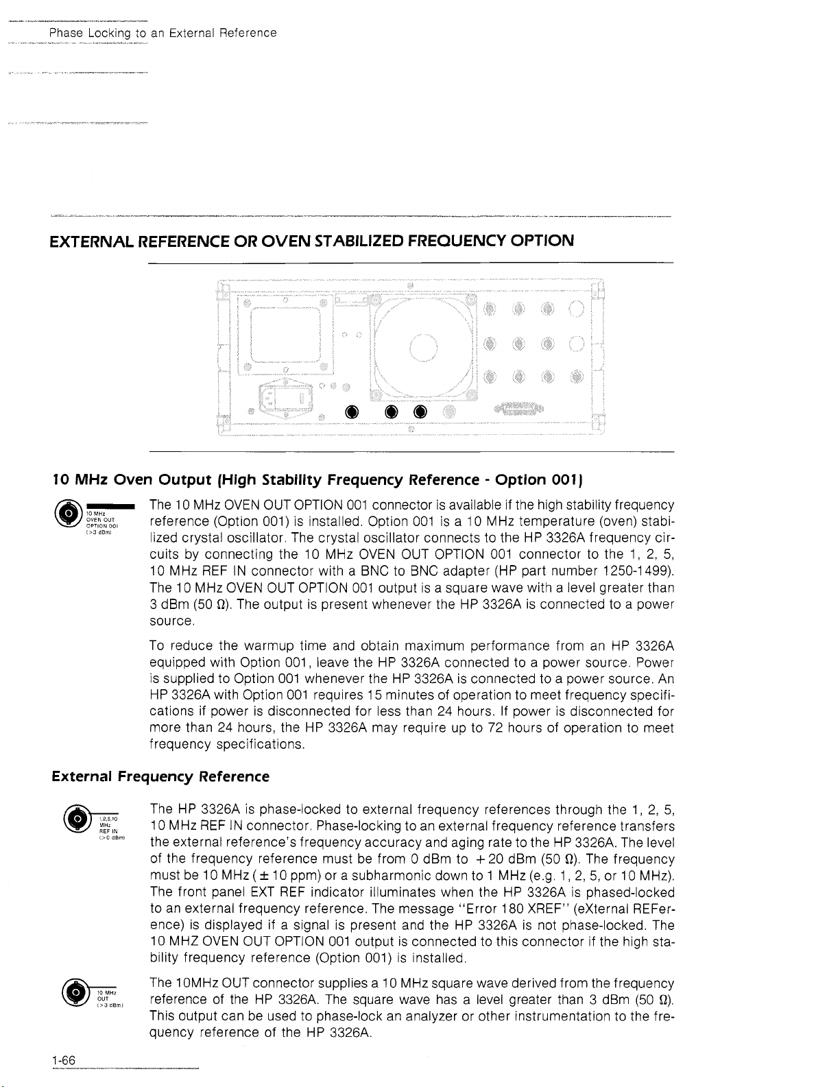
--
"-
Phase Lock~ng to an External Reference
EXTERNAL REFERENCE OR OVEN STABILIZED FREQUENCY OPTION
10
MHz
@-
Oven Output
OVEN
OUT
OPTION
001
1'3
dBml
The 10 MHz OVEN OUT OPTION 001 connector is available if the high stability frequency
reference (Option 001) is installed. Option 001 is a 10 MHz temperature (oven) stabilized crystal oscillator. The crystal oscillator connects to the HP
(High
cuits by connecting the
10 MHz REF IN connector with a BNC to BNC adapter (HP part number 1250-1499).
The 10 MHz OVEN OUT OPTION 001 output is a square wave with a level greater than
3
dBm (50 R). The output is present whenever the HP 3326A is connected to a power
source.
To reduce the
warmup time and obtain maximum performance from an HP 3326A
equipped with Option 001, leave the HP 3326A connected to a power source. Power
is supplied to Option 001 whenever the HP 3326A is connected to a power source. An
HP 3326A with Option 001 requires 15 minutes of operation to meet frequency specifications if power is disconnected for less than 24 hours. If power is disconnected for
more than 24 hours, the HP
frequency specifications.
External Frequency Reference
@-
,,,,,
l>O
The HP 3326A is phase-locked to external frequency references through the 1,
10 MHz REF IN connector. Phase-locking to an external frequency reference transfers
dBml
the external reference's frequency accuracy and aging rate to the HP 3326A. The level
of the frequency reference must be from 0 dBm to
must be 10 MHz
(+
The front panel EXT REF indicator illuminates when the HP 3326A is phased-locked
to an external frequency reference. The message "Error 180 XREF" (external
ence) is displayed if a signal is present and the HP 3326A is not phase-locked. The
MHz OVEN OUT OPTION 001 output is connected to this connector if the high sta-
10
bility frequency reference (Option 001) is installed.
Stability Frequency Reference - Option 001)
3326A frequency cir-
10 MHz OVEN OUT OPTION 001 connector to the
I,
2, 5,
3326A may require up to 72 hours of operation to meet
2,
+
20 dBm (50 R). The frequency
10 ppm) or a subharmonic down to 1 MHz (e.g. 1, 2, 5, or 10 MHz).
REFer-
5,
1 OMHz OUT connector supplies a 10 MHz square wave derived from the frequency
The
,
reference of the HP 3326A. The square wave has a level greater than 3 dBm (50 R),
This output can be used to phase-lock an analyzer or other instrumentation to the frequency reference of the HP
3326A.
Page 77

CHAPTER
2
HP-IB OPERATION
Page 78

Chapter
2
.
Table
of
Contents
DESCRIPTION OF THE HP-IB
HP 3326A HP-16 CAPABILITY
HP-IB INTERFACE MANAGEMENT LINES
TALK 1 LISTEN ADDRESSES
............
...........
...
..............
VIEWING THE HP 3326A HP-IB ADDRESS
CHANGING THE HP 3326A HP-IB ADDRESS
BUS MESSAGES
SERVICE REQUEST
THE STATUS BYTE
MASKING THE STATUS BYTE
......................
.....................
....................
...........
.
.
Page 79

Qservice ----- This Document is a complete scan from the Original HP - Agilent Manual ----- Qservice
Page 80

HP-IB
Capab~l~ty
HP 3326A HP-IS CAPA
The HP 33268 interfaces to the HP-IB as defined by IEEE Standard
terface functional subset which the HP 3326A implements is specified in Figure
HP-IS INTERFACE MANAGEMENT LINES
Five lines in the HP-IB manage the orderly flow of information across the HP-IB. Figure
2-3 describes the lines used in managing the HP-IB.
488-1
978.
The in-
2-2.
TALKlLlSTEN ADDRESSES
Each HP-IB device has at least one talk, and one listen address (unless the device is
totally transparent, or a talk only or listen only device). Device addresses are used by
the active controller in the COMMAND MODE (ATN true) to specify the talker (via a
talk address) and the listener (via listen addresses). There may be only one talker addressed by the controller to talk at any time.
Page 81

TalklL~sten Addresses
The address of a device is usually preset at the factory and is resettable during system
configuration. In the binary representation of the address, the device address is the
decimal equivalent of the five least significant bits of the address. (On HP-IB devices
with selector switches, these are the five address switches.) The address can be from
0
to
30
inclusive. The sixth and seventh bits determine
if
the address is a talk or listen
address respectively. High level HP-IB controllers typically configure these two bits au-
2-4
tomatically. Figure
lists the HP-IB addresses if a controller requires the talk and
listen addresses.
Page 82

ViewingIChanging
HP-IB
Address
The talk and listen addresses fall within the printable ASCII character set. When a device
receives one of these characters while ATN is true, it becomes addressed. The ASCII
character
"?"
(ASCII 31) unaddresses all devices while ATN is true. The device address (set from the HP 3326A front panel) is used by HP-IB controllers most of which
automatically send the talk and listen address characters.
VIEWING THE HP 3326A HP-IB ADDRESS
The HP-IB address of Phe HP 3326A is stored in a nonvolatile memory (there are no
address switches). The HP 3326A address appears in the display when the BUS AD-
DRESS key in the HP-IB STATUS block is pressed. The BUS ADDRESS key is selected
by pressing the blue SHIFT key followed by the LOCAL key. The HP 3326A address
is removed from the display by pressing another key that requires the display.
CHANGING THE HP 3326A HP-IB ADDRESS
Every device on the HP-IB must have a unique address. The HP 3326A address can
be set at any address between 0 and 30, inclusive and is stored in internal nonvolatile
memory. When selecting an address, remember that the controller also has an address
(usually 21). To change the HP-IB address:
Press the blue SHIFT key followed by the LOCAL key in the HP-IB
STATUS block to display the HP-IB address.
Enter the address with the numeric keypad. For two digit HP-IB ad-
dresses, the address is set when the second digit is entered. For
a single digit HP-IB address, the address is set when any units key
is pressed. Alternately, a zero can precede the single digit to form
a two digit address.
The HP-IB address is reset to
clear opera tion.
The message "Error 20 RNGE" is displayed if the HP-IB address exceeds 30.
BUS MESSAGES
NOTE
18
after a memory
The HP-IB interface system operates in either of two modes: command mode (ATN bus
management line true) or data mode (ATN bus management line false).
If
an HP controller is used, the bus management lines are configured automatically and all necessary command strings are issued.
In the command mode, devices on the HP-IB can be addressed or unaddressed as
listeners or talkers. Bus commands are also issued in the command mode. These commands may instruct the HP-IB interface to control the instrument (like CLEAR or TRIGGER) but are more often used for bus management (REMOTE, LOCAL,
POLLS, SERV-
Page 83

Bus
Messages
ICE REQUEST, ABORT interface activity, or PASS CONTROL). Bus commands are issued
through one of the bus management lines or through the eight bit data bus. Figure 2-5
lists the commands used in the command mode.
In the data mode, data or instructions are transferred between instruments on the
HP-IB. Instructions transferred to the instrument are called device dependent commands. All the commands specifically for the HP
3326A fall into this category. The
HP 3326A device dependent commands configure the HP 3326A, initiate measurements,
initiate data transfers, or define error reporting conditions. These device dependent
commands are meaningless for other instruments. The HP
3326A device dependent
commands are listed in Chapter Ill.
Page 84

One of the five bus management lines connected to every device on the bus is the SRQ
line. The SRQ line is used by a device to indicate the need for attention from the con-
troller. When the
the front panel SRQ indicator, and generates the SRQ, Bit six, the require service bit,
is sometimes referred to as the status bit in connection with a poll. Any bit in the status
byte may initiate an SRQ. The status byte may be masked to select which bits cause
the
HP
3326A
When a controller senses an SRQ, it can poll each device to fine the device requiring
service. The
HP
3326A
to set the SRQ line.
HP
3326A
requires service, it sets bit six of the status byte, illuminates
responds to a serial poll by returning its status byte.
Page 85

THE STATUS BYTE
The status byte is an eight bit word transmitted by the HP 3326A in response to a serial
poll. The state
2-6 describes the HP 3326A status byte bit positions, and the events and conditions
that set and reset each bit. Any status bit becomes enabled (set) when the condition
it represents changes from false to true. An enabled bit sets bit 6, and generates an
SRQ
if the Boolean
Statbs
of
each bit indicates the status of an internal HP 3326A function. Figure
AND
of the status byte and the status byte mask is not equal to zero.
Byte
Page 86

Masking the Status Byte
MASKING THE STATUS BYTE
The
HP
3326A MASK command specifies which bits in the status byte will be enabled
to generate an SRQ. The MASK command has the syntax of "MASKnPC" where n is
an integer number corresponding to the enabled bits in the status byte, and PC is the
suffix used to end the command. The integer number is determined by summing the
decimal values of the enabled bits in the status byte. Figure 2-6 describes the HP 3326A
status byte and lists the decimal value of each bit position. The require service bit (bit
6) cannot be disabled.
Page 87

CHAPTER 3
HP 3326A HP-IB COMMANDS
Page 88

Chapter
3
.
Table of Contents
REMOTE FRONT PANEL OPERATION
COMMAND SYNTAX 3.1
BUSMODES 3-3
...........................................
..............................
VIEWING THE HP 3326A HP-IB ADDRESS
CHANGING THE HP 3326A HP-IB ADDRESS
INTERROGATING THE HP 3326A FOR SETUP PARAMETERS
DISPLAYING THE HP 3326A SETUP PARAMETERS
MODIFYING PARAMETERS
DISPLAY CONTROL
...........
...................................
SAVING OR RESTORING AN HP 3326A SETUP
HP 3326A IDENTIFICATION
TRIGGERED SWEEPS
...................................
..........................
READING AND MASKING THE STATUS BYTE
ERROR CODES
HP 3325A COMPATIBILITY
UNITS
..............................
....................................
............................
HP 3326A MNEMONICS SUMMARIES
...................
...................
...................
.....
..............
. . .
...............
............
.........
.........
........
3.1
3.3
3.4
3.4
3-4
.3-5
3-6
3.6
3-7
3-8
3-8
3-10
3-12
3-13
3-14
Page 89

Qservice ----- This Document is a complete scan from the Original HP - Agilent Manual ----- Qservice
Page 90

-
Command
Syntax
HP-IB command requiring a range value or a suffix, the applicable range limit and suffix
are also listed. The following conventions apply to the HP 3326A HP-IB commands:
The HP 3326A accepts data in seven bit ASCII code and ignores the
eighth (parity) bit.
All characters other than A through
(+),
minus
(-),
period
(.),
question mark
Z,
a through z, 0 through
(?),
and pound sign
9,
(#)
plus
are
treated as command separators. Command separators may not be
embedded in an HP-IB command mnemonic.
Two successive HP 3326A HP-IB commands must be separated by
a command separator, or the last character of the first command
may be sent with EOI.
Range values may be in integer, real, or exponential form. For positive values, only the first eleven digits of the mantissa are used. For
negative values, only the first ten digits of the mantissa are used.
Leading zeros before the decimal point are ignored.
An HP-IB mnemonic must precede any setup data or suffix.
After information is requested from the HP 3326A, the HP 3326A
responds with the information when it is addressed to talk.
The HP
COMMAND FORM EXAMPLE EXAMPLE DESCRIPTION
3326A uses the following forms for HP-IB commands:
Mnemonic EOS "CHA" Channel A
Mnemonic Suffix EOS "FCNA SIN" Sine function for channel A
Mnemonic Data EOS "HVA
Mnemonic Range data Suffix EOS
?
Mnemonic
EOS
0" High voltage off
"AM
1
VO" Amplitude of 1 Vrms
"FR?"
l nterrogate frequency
where:
-
mnemonic is the HP-IB mnemonic
-
EOS indicates the end of
string marker (a command separator, typically the carriage return
and line feed supplied by the controller)
-
suffix is an alphabetic code for units, function, or mode
-
data is a numeric code for a function or mode
-
range data
-
?
is used to interrogate the HP 3326A
is
the value for an entry parameter
A program string for the HP 3326A may contain multiple HP-IB commands such as "CHA FCNA SIN HVAO AM1VO FR?" For a program
string, a command separator (in this example, a space) is required
between HP-I6 commands.
Page 91

Bus
Modes
The HP 3326A accepts data and commands from the HP-IB in either of two modes:
1
bus mode 1 or bus mode 2. Bus mode
Bus mode 2 should be used if speed of communications is a critical factor in the HP-IB
system.
BUSMl
In BUSMl (BUS Mode I), the default operating mode, the HP 3326A processes one
character (byte) at a time. That is, the controller must wait for the HP 3326A to finish
processing a previously accepted character before the HP
tional character in the command.
is the default operating mode for the HP 3326A.
3326A will accept an addi-
NOTE
In bus mode
characters. If a measurement sequence is started
immediately after issuing a command to the
3326A, the HP 3326A may not have finished
HP
processing the last command. To check if the
HP
3326A command processing is complete, mo-
nitor the ready bit in the status byte with a serial
poll, or mask the status byte ready bit and monitor
the
SRQ
status of commandprocessing is to issue the command WAIT, The HP
handshake on the command WAIT until the last
character is accepted. This insures that the previous command has been processed.
When BUSM2 (BUS Mode
of HP-IB data. While the buffered characters are being processed, the controller can
communicate with other devices on the bus. If the buffer becomes full, the HP
does not complete the HP-IB handshake (i.e. delays the controller) and will not accept
additional characters until all the buffered characters are processed. To check if the
HP
3326A command processing is complete, monitor the ready bit in the status byte
with a serial poll, or mask the status byte ready bit and monitor the SRQ line.
I,
the HP 3326A buffers up to three
line. An alternate approach to check the
3326A does not finish the
2)
is in effect, the HP 3326A buffers up to
100
characters
3326A
VIEWING
THE HP
The HP-IB address of the HP 3326A is stored in nonvolatile memory (there are no address switches). The HP 3326A address appears in the display when the BUS ADDRESS
key in the HP-IB STATUS block is pressed. The BUS ADDRESS key is selected by pressing the blue SHIFT key followed by the LOCAL key. The HP 3326A address is removed
from the display by pressing another key that requires the display.
3326A
HP-18
ADDRESS
Page 92

Changing the
HP-IB
Address
CHANGING THE HP 3326A HP-16 ADDRESS
The HP 3326A address can be set at any address between 0 and 30, inclusive. The
HP-IB address of the HP 3326A is set to 18 at the factory and stored in nonvolatile
memory. When selecting an address, remember that the controller also has an address
(usually 21).
To change the HP-IB address:
Press the blue SHIFT key followed by the LOCAL key in the HP-IB
STATUS block to display the HP-IB address.
Enter the address with the numeric keypad. For two digit HP-IB addresses, the address is set when the second digit is entered. For
single digit HP-IB addresses, the address is set when any units key
is pressed. Alternately, a zero can precede the single digit to form
a two digit address.
NOTE
The HP-IB address is reset to
clear opera tion.
The message "Error 20 RNGE" is displayed if the HP-IB address ex-
ceeds 30.
18
after a
memory
INTERROGATING THE HP 3326A FOR SETUP PARAMETERS
The value of a setup parameter is read over the HP-IB by sending the parameter HP-IB
mnemonic followed by a question mark
the parameters that can be interrogated and the form of the response. For example,
sending the mnemonic FR? sets up the HP
for the selected channel. The frequency value is transmitted when the HP 3326A is
addressed to talk. Each value is returned with units.
The HP 3326A always responds with the units Hertz for frequency values, volts peak-
to-peak for amplitude values, seconds for time values, volts dc for offset values, degrees
for phase, and percent for duty cycle. The HP
degrees for modulat~on level. Each interrogation response ends with a carriage return
(ASCII 13) and line feed (ASCII 10) character.
(?).
The HP-IB command summary table lists
3326A to respond with the frequency value
3326A responds with either percent or
DISPLAYING THE HP 3326A SETUP PARAMETERS
The current value for a setup parameter is displayed on the HP 3326A front panel if
the corresponding HP-IB mnemonic is sent without data and a suffix. For example, send-
ing the mnemonic AM displays the amplitude value for the selected channel but does
not change the amplitude value.
Page 93

Modifying
Parameters
The units for the displayed value of a setup parameter change to new units if the corresponding HP-IB mnemonic and new suffix are sent without data. For example, sending the mnemonic AM DBV displays the current amplitude value in
dBV for the selected
channel. Sending the AM DBV command does not change the amplitude value.
NOTE
MODIFYING
If the display is disabled with the DSPO
command, the requested value is not displayed.
or
DSP
OFF
PARAMETERS
The HP 3326A modify functions are implemented over the HP-IB with the ElNC (Entry
INCrement), UP, and DN (DowN) HP-IB commands. The TDN (Trigger DowN) and TUP
(Trigger UP) HP-IB commands enable the HP
display value whenever a trigger is received. The front panel modify controls are ena-
bled (for local operation) and disabled with the MFY (ModiFY) command.
ElNC
The amount to increment or decrement the display value is set with the ElNC (Entry
INCrement) HP-IB command. The ElNC command includes a positive range value and
a suffix applicable for the value to be modified. Values entered with the ElNC command
apply only to the UP, DN, TUP, and TDN HP-IB commands. Only one ElNC value is
stored internally by the HP
3326A. An error is generated if the display is incremented
or decremented and the ElNC command suffix is not compatible with the units of the
displayed value. An example of the ElNC command is EINC10.2KHZ.
MFYO
or
MFY OFF
The MFYO (ModiFY) or MFY OFF command disables the front panel modify controls
and inhibits the flashing digit on the front panel display.
3326A to increment or decrement the
MFYl
or
MFY
ON
The MFYl (ModiFY) or MFY ON command enables the front panel modify controls. The
HP 3326A must be put into local before the HP 3326A accepts changes through the
modify controls.
TUP
and
TDN
The TUP (Trigger UP) and TDN (Trigger DowN) HP-IB commands enable the HP 3326A
to increment or decrement the display value by the increment set with the ElNC
mnemonic whenever a trigger is received. The HP
3326A responds to either a trigger
applied through the rear panel EXT TRIG (EXTernal TRIGger) connector, or to the
HP-IB group execute trigger command. The TUP and TDN commands do not require
a range value or suffix.
Page 94

Display Control
TOFF
The TOFF (Trigger OFF) command disables trigger operations on the HP 3326A. Trig-
ger operations are enabled when power is applied, after an instrument preset, or with
the TDN, TUP, STC, and STS HP-IB commands.
UP
and
The UP and DN (DOWN) commands increment and decrement the display value by the
increment set with the ElNC mnemonic. The UP and DN commands do not require a
range value or suffix.
DISPLAY CONTROL
DN
DlSPO
or
DlSP OFF
The DlSPO (DISPlay) or DlSP OFF command inhibits the HP 3326A from displaying setup
values on the front panel display. While the display is disabled, dlSP OFF (display OFF)
appears in the display and all front panel indicators (except the HP-IB Status) are extinguished. The display is returned to normal with the
NOTE
DlSPl
or
DlSP ON
If the HP
play disabled, the HP
front panel ke ys. To restore the HP
panel operation without a controller, apply power
with the shift key depressed (a memory clear operation).
nonvolatile memory with preset state setup data,
and changes the HP-IB address to
3326A
A
memory clear replaces the contents of the
is returned to local with the dis-
3326A
The DlSPl (DISPlay) or DlSP ON command enables the HP 3326A to display setup values
on the front panel display. The DlSPl or DlSP ON command is necessary only if the
HP 3326A display is disabled during HP-IB operation.
SAVING OR RESTORING AN HP 3326A SETUP
DlSPl or DlSP ON command.
will not respond to the
3326A
to front
18.
The contents of any HP 3326A memory register can be accessed over the HP-IB. The
data is transferred over the HP-IB in binary form with the LRN (LeaRN) and PRG (PRo-
Gram) mnemonics. This binary form is useful for storing HP 3326A setup data in external memory for more permanent storage. The SAV
(SAVe) mnemonic stores HP 3326A
setup data in internal nonvolatile memory, and the RCL (ReCaLI) mnemonic recalls
HP 3326A setup data from internal nonvolatile memory.
Page 95

Saving or Restoring a Setup
LRN
The LRN (LeaRN) command, combined with an integer, configures the HP 3326A to
transfer the setup data stored in the nonvolatile memory register over the HP-IB. The
LRN command has the syntax of LRNn where n ranges from 0 to 9 and represents the
nonvolatile memory register to transfer. After the HP
ASCII characters #A followed by two length bytes and 168 bytes of binary data are trans-
mitted by the HP
nificant bytes of the number of bytes transmitted. The binary transmission is ended with
the HP-IB EOI bus management line being asserted on the last byte. Note that the controller must read the data after issuing this command.
PRG
3326A. The length bytes represent the most significant and least sig-
3326A is addressed to talk, the
The PRG (PRoGram) command, combined with an integer ranging from 0 to 9, prefaces
the 172 bytes of binary setup data to be loaded into the HP 3326A nonvolatile memory.
The integer specifies the nonvolatile memory register to receive the binary setup data.
The new setup is set after the last data word is received. Data loaded into the HP
must be data output by the LRN command. The received HP-IB data is checked inter-
nally to insure data integrity.
RCL
The RCL (ReCaLI) command, combined with an integer, recalls a stored instrument setup
from internal memory to the current HP 3326A setup. The RCL command has the syn-
tax of RCLn where n is an integer ranging from 0 to
of the stored the setup data.
S
AV
The SAV (SAVe) command, combined with an integer, stores the current HP 3326A setup
in internal memory. The SAV command has the syntax of SAVn where n is an integer
ranging from
HP
3326A IDENTIFICATION
ID?
The ID command transmits the HP 3326A identification code (HP3326A) to the remote
interface.
3326A
9
and represents the memory register
0
to 9 and represents the memory register to receive the setup data.
REV?
The REV? command transmits a pair of revision date codes (the revision and capability
date) for the program stored in the HP 3326A read only memory. The date code pair
is transmitted as
since 1960 is represented by the first two digits, and the week is represented by the
second two digits in each number.
nnnn,nnnn where nnnn represents each four digit integer. The year
Page 96

Triggered Sweeps
SER?
The SER? (SERial number) command transmits a ten character string stored in the
HP 3326A read only memory. The ten character string has the form of nnnnAOOOO where
nnnn represents an integer corresponding to the revision date for the HP 3326A soft-
ware. The year is represented by the first two digits, and the week is represented by
the second two digits. The next character in the string is the
the remaining characters are zeros. The actual serial number of the HP
stored in memory.
TRIGGERED SWEEPS
The sweep functions of the HP 3326A operate under trigger control when the STC (Sweep
Triggered Continuous) or STS (Sweep Triggered Single) HP-IB commands are in effect.
The HP 3326A responds to either a trigger applied through the rear panel EXT TRIG
(EXTernal TRIGger) connector or to the HP-IB group execute trigger command. Refer
to the controller operating manual for implementation of the group execute trigger
command.
ASCII character A, and
3326A is not
STC
The STC (Sweep Triggered Continuous) command enables the HP 3326A to initiate a
continuous sweep when a trigger is received. A sweep in progress is stopped after the
STC command is issued. The shortest delay
start occurs when the trigger is preceded by the SRE (Sweep REset) command.
STS
The STS (Sweep Triggered Single) command enables the HP 3326A to initiate a single
sweep when a trigger is received. A sweep in progress is stopped after the STS command is issued. The shortest delay
(5
10 IS) between a trigger and sweep start occurs
when a trigger is preceded by the SRE (Sweep REset) command.
TOFF
The TOFF (Trigger OFF) command disables trigger operations on the HP 3326A. Trigger operations are enabled when power is applied, after an instrument preset, or with
the TDN, TUP, STC, and STS HP-IB commands.
READING AND MASKING THE STATUS BYTE
The MASK command specifies which bits in the status byte are enabled to generate
an SRQ. The status byte is an eight bit word that the HP 3326A outputs when requested
by a serial poll. The state of each bit indicates the status of an internal HP
tion. A service request is generated when the Boolean AND of the status byte and status byte mask is not equal to zero.
(I
10 IS) between a trigger and sweep
3326A func-
Page 97

Status
Byte
MASK
The MASK command has the syntax of MASKnPC where n is an integer corresponding
to the enabled bits in the status byte, and PC is the suffix used to end the command.
The integer is determined by summing the decimal values of the enabled bits in the
HP
status byte. Figure
of each bit position. The require service bit (bit 6) cannot be disabled and mask programming for this bit is ignored.
3-1 describes the
3326A status byte and lists the decimal value
Page 98

Error
Codes
Examples: To enable the error bit (bit
send the command MASK32PC. To enable the error bit (bit
32) and ready bit (bit 4 with a decimal value of
mand MASK48PC where 48 is the sum of
ERROR CODES
ERR?.
The ERR? command transmits
register, and resets the error bits in the status byte. Bit
either a program error or hardware error occurs. Bit
occurs, and bit 3 is also set when a hardware error occurs. Figure 3-2 summarizes
the error codes and Appendix A provides additional detail on the error codes.
5
with a decimal value of 32) to generate an SRQ,
5
with a decimal value of
16)
to generate an SRQ, send the com-
16
plus 32.
the
code for the last error that occurred, resets the error
5
in the status byte is set when
0
is also set when a program error
Page 99

Error
Codes
Page 100

ibility
For compatibility with existing programs, the HP 3326A supports many of the HP 3325A
SynthesizerIFunction Generator HP-IB commands. The major changes required in adapt-
ing an HP
3325A program for HP 3326A operation are adding the CHA or CHB command to specify the affected channel of the HP 3326A, and reducing frequency values
greater than 13 MHz. Figure 3-3 lists the mnemonics unique to HP 3325A that are recog-
nized by the HP
terrogations for entered values that have the letter
3326A. For HP 3325A compatibility, the HP 3326A also recognizes in-
I
preceding the mnemonic,
 Loading...