

Page 1

User’s and Service Guide
Publication Number 33120-90022
Edition 2, March 2002
© Copyright Agilent Technologies, Inc. 1994-2002
For Safety information, Warranties, and Regulatory information,
see the last page in this manual.
Agilent 33120A
Option 001 Phase-Lock Assembly
Page 2

Contents
Chapter 1 Quick Start
The Rear Panel at a Glance 3
The Front-Panel Menu at a Glance 4
To phase lock to an external clock signal 5
To phase lock multiple function generators 7
To set a zero phase reference 9
To phase lock using the triggered burst mode 10
To generate a phase unlock error 14
Chapter 2 Remote Interface Operation
SCPI Command Summary 17
Phase-Lock Commands 18
Simplified Programming Overview 20
The SCPI Status Registers 23
Status Reporting Commands 26
Phase-Lock Error Messages 26
Chapter 3 Specifications 27
Chapter 4 Replaceable Parts and Schematics
To Order Replaceable Parts 30
Replaceable Parts Lists 31
Manufacturer’s List 33
33120-66503 Component Locator Diagram 34
33120-66503 Schematic Diagram 35
Index 37
ii
Page 3

1
1
Quick Start
Page 4

Quick Start
This manual contains supplemental information for the Agilent 33120A
Phase-Lock assembly. Refer to the 33120A User’s Guide and
Service Guide for complete details on using the function generator.
The Phase-Lock assembly (Option 001) adds the following capabilities
to the 33120A Function / Arbitrary Waveform Generator:
External clock input and output connectors on the rear panel.
These connectors allow synchronization between multiple 33120As
or to an external 10 MHz clock signal.
Phase offset control from the front panel or over the remote interface.
Simultaneous hardware triggering of multiple Agilent 33120As.
Option 001 allows the 33120A to generate a trigger pulse from
the Ext Trig terminal which can be routed to other instruments in
a system.
2 ppm timebase—10 times the frequency stability of the standard
Agilent 33120A.
If you have questions relating to the operation of the function generator,
call
1-800-452-4844 in the United States, or contact your nearest
Agilent Technologies Sales Office.
2
Page 5
Chapter 1 Quick Start
The Rear Panel at a Glance
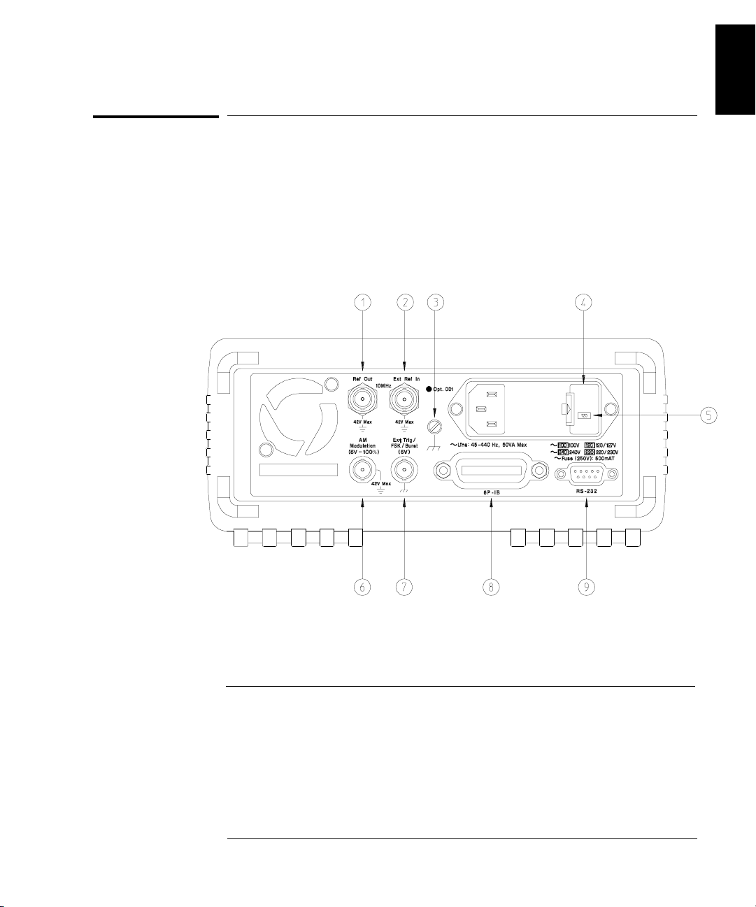
The Rear Panel at a Glance
The Phase-Lock assembly adds the Ref Out and Ext Ref In terminals
to allow synchronization between multiple 33120As or to an external
10 MHz clock signal.
1
1 Internal 10 MHz reference output terminal
2 External 10 MHz reference input terminal
3 Chassis ground
4 Power-line fuse-holder assembly
5 Power-line voltage setting
6 AM modulation input terminal
7 External Trigger / FSK / Burst modulation
input terminal
8 GPIB (IEEE-488) interface connector
9 RS-232 interface connector
3
Page 6
Chapter 1 Quick Start
The Front-Panel Menu at a Glance
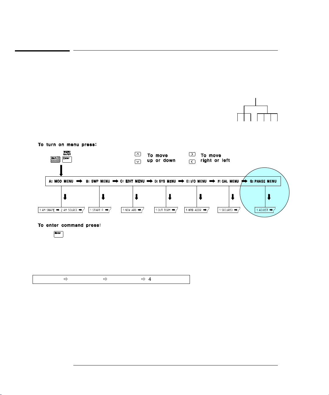
The Front-Panel Menu at a Glance
The Phase-Lock assembly adds the Phase Menu to the front-panel menu.
The menu is organized in a top-down tree structure with three levels.
G: PHASE MENU
1: ADJUST Õ 2: SET ZERO Õ 3: TRIG OUT Õ 4: UNLOCK ERR
1: ADJUST
2: SET ZERO
3: TRIG OUT
4: UNLOCK ERR
Sets the phase offset of the output waveform to a value in degrees.
Nulls the phase offset to a zero reference for relative adjustments.
Enables or disables an external trigger from the Ext Trig terminal.
Enables or disables error generation when phase-lock is lost.
4
Page 7
Chapter 1 Quick Start
To phase lock to an external clock signal
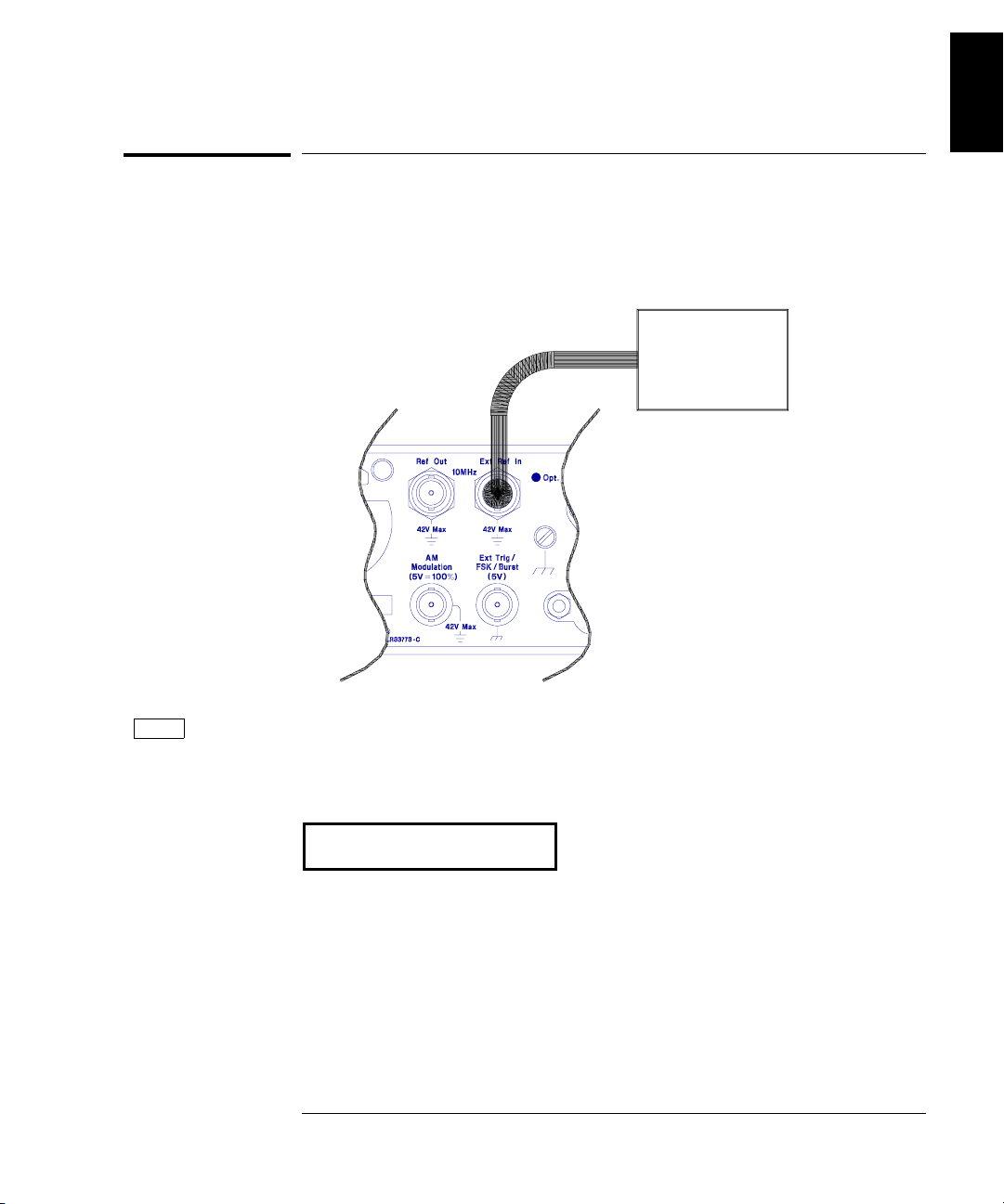
To phase lock to an external clock signal
The rear-panel Ext Ref In terminal allows you to synchronize one or
more function generators with an external 10 MHz signal. The following
steps show you how to configure a single instrument for synchronization
with an external signal.
External
10 MHz
Signal
1
Freq
1 Select the function and set the output frequency to 10 MHz.
You must select either sine or square wave since the other output
waveforms cannot be used up to 10 MHz.
10.000,000 MHz
To adjust the phase offset, you will use the front-panel menu as described
on the following page.
5
Page 8
Chapter 1 Quick Start
To phase lock to an external clock signal
Shift
Menu On/Off
<
¿
¿
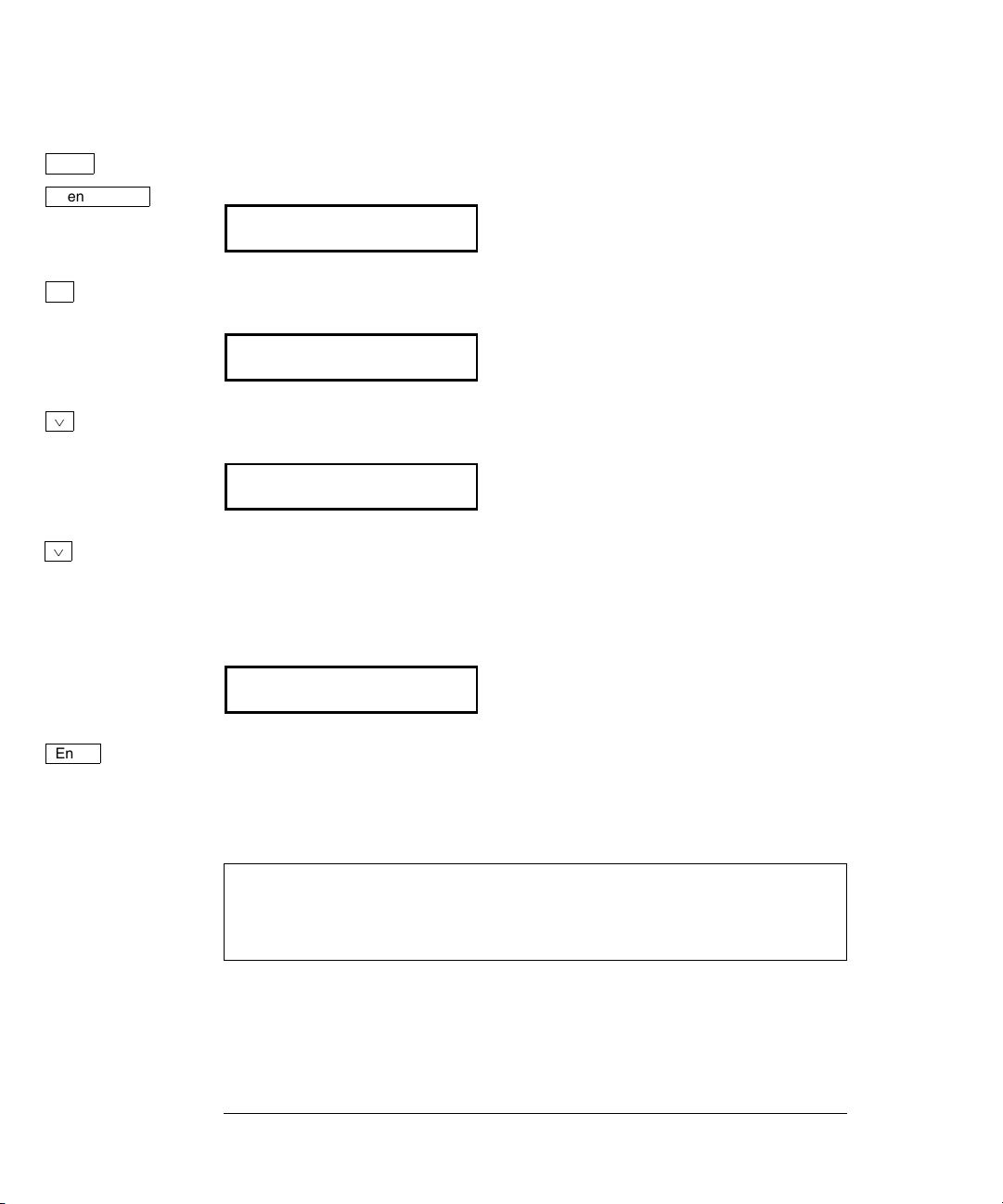
2 Turn on the menu.
A: MOD MENU
3 Move across to the
PHASE MENU choice on this level.
G:PHASE MENU
4 Move down a level to the
ADJUST command.
1: ADJUST
5 Move down a level and set the phase offset.
You can set the offset to any value between -360 degrees and +360 degrees.
The displayed phase is output “real time” unless you have selected the
arbitrary waveform function.
¾000.000 DEG
Enter
6 Turn off the menu.
The function generator beeps and displays a message. You are then
exited from the menu.
At this point, the function generator is phase-locked to the external clock
signal with the specified phase relationship. The two signals will
remain locked unless you change the function or output frequency.
6
Page 9
Chapter 1 Quick Start
To phase lock multiple function generators
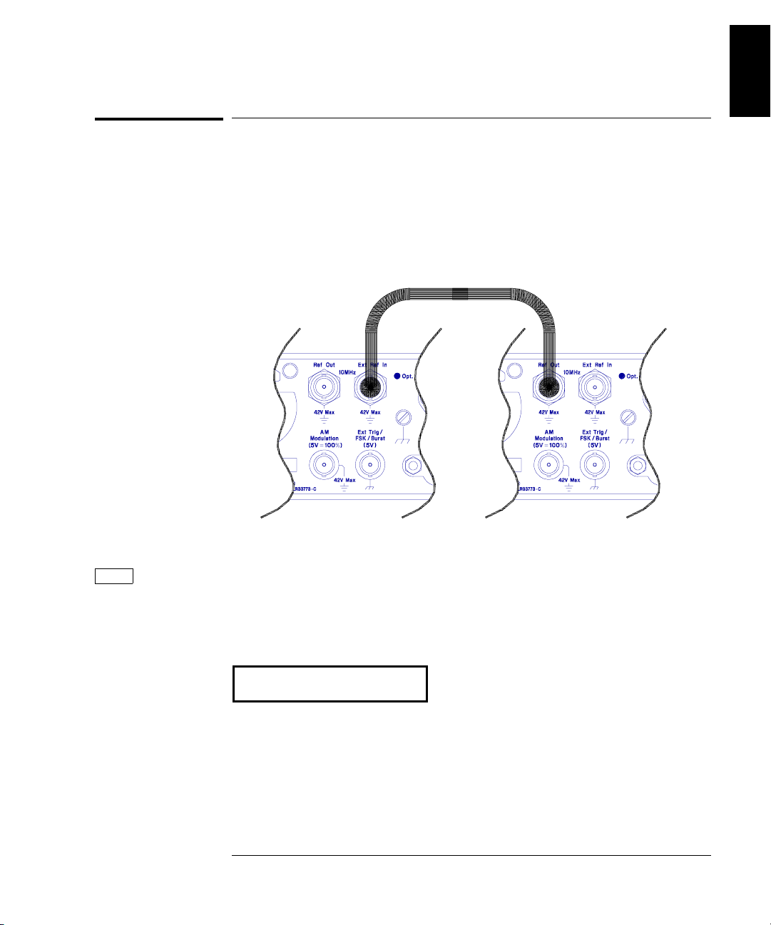
To phase lock multiple function generators
The rear-panel Ref Out and Ext Ref In terminals allow you to
synchronize multiple function generators. The diagram below shows
how to make connections for the “real-time” phase-lock mode. In the
real-time mode, the phase offset relationship is random at first. You can
adjust the phase offset “real time” from the front panel. The following
steps show you how to synchronize two function generators at 10 kHz.
1
Freq
1 Set both instruments to the same output frequency.
You can select sine, square, ramp, or triangle waveforms for phase-lock
operation. You cannot perform real-time phase adjustments on arbitrary
waveforms.
10.000,000 KHz
To adjust the phase offset, you will use the front-panel menu as described
on the following page.
7
Page 10
Chapter 1 Quick Start
To phase lock multiple function generators
Shift
Menu On/Off
<
¿
¿
2 Turn on the menu.
A: MOD MENU
3 Move across to the
PHASE MENU choice on this level.
G:PHASE MENU
4 Move down a level to the
ADJUST command.
1: ADJUST
5 Move down a level and set the phase offset.
You can set the offset to any value between -360 degrees and +360 degrees.
The displayed phase is output “real time” unless you have selected the
arbitrary waveform function.
¾000.000 DEG
Enter
6 Turn off the menu.
The function generator beeps and displays a message. You are then
exited from the menu.
At this point, the two function generators are phase-locked with the
specified phase relationship. The two signals will remain locked unless
you change the function or output frequency.
8
Page 11
Chapter 1 Quick Start
To set a zero phase reference
To set a zero phase reference
After selecting the desired phase relationship as described on the
previous pages, you can set a zero-phase point. The function generator
then assumes that its present phase is zero and you can adjust the
phase relative to this new “zero”.
1
Shift
Menu On/Off
<
¿
>
¿
1 Turn on the menu.
A: MOD MENU
2 Move across to the
PHASE MENU choice on this level.
G:PHASE MENU
3 Move down a level and then across to the
SET ZERO command.
2: SET ZERO
4 Move down a level to set the zero phase reference.
The displayed message indicates that the phase reference will be set
to zero degrees (you must exit the menu to select the displayed value).
PHASE = 0
Enter
5 Save the phase reference and turn off the menu.
The function generator beeps and displays a message to show that the
change is now in effect. You are then exited from the menu.
9
Page 12
Chapter 1 Quick Start
To phase lock using the triggered burst mode
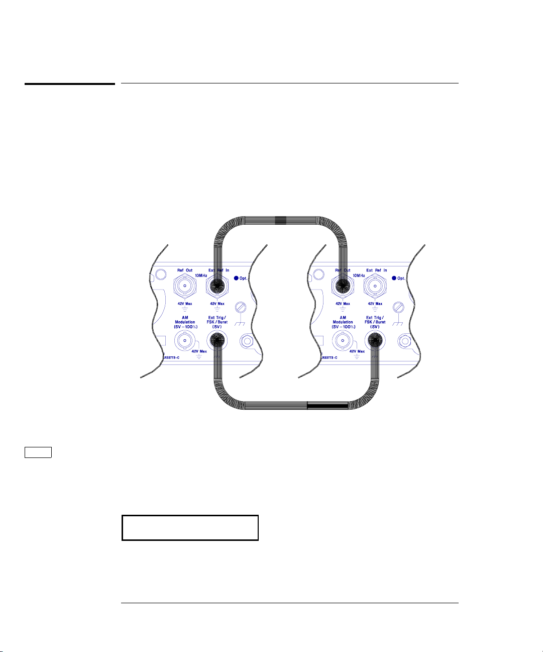
To phase lock using the triggered burst mode
The rear-panel Ref Out and Ext Ref In terminals allow you to
synchronize multiple function generators. The diagram below shows
how to make connections for the “triggered burst” phase-lock mode.
In the triggered burst mode, you can synchronize phase-lock signals
using an external trigger from the rear-panel Ext Trig terminal.
The following steps show you how to synchronize two function
generators at 10 kHz in the triggered burst mode.
Freq
1 Set both instruments to the same output frequency.
You can select sine, square, ramp, or triangle waveforms for phase-lock
operation. You cannot perform real-time phase adjustments on arbitrary
waveforms.
10.000,000 KHz
10
Page 13

Shift
Burst
Chapter 1 Quick Start
To phase lock using the triggered burst mode
1
2 Enable the burst mode on both instruments.
Shift
<
Recall Menu
¿
Enter
Notice that the
Burst annunciator turns on.
3 Use the menu to set the burst count on both instruments.
After you enable the burst mode, the “recall menu” key will
automatically take you to the
BURST CNT command in the MOD MENU.
4: BURST CNT
4 Move down to the parameter level and set the count to “
Press the right or left arrow keys until the “
Then, press the down arrow key to display “
CYC” units are flashing.
INFINITE”.
INFINITE”.
INFINITE
5 Save the change and turn off the menu.
The function generator beeps and displays a message to show that the
change is now in effect. You are then exited from the menu.
ENTERED
Next, you will set up the starting phase of the burst as shown on
the next page.
11
Page 14

Chapter 1 Quick Start
To phase lock using the triggered burst mode
Shift
Menu On/Off
¿
Enter
6 Go to the BURST PHAS command in the MOD MENU.
6:BURST PHAS
7 Move down a level and set the burst phase.
You can set the starting phase of the burst to any value between
-360 degrees and +360 degrees. With the
BURST PHAS command,
the phase adjustment is not “real time”; you must exit the menu
to output the specified starting phase.
¾000.000 DEG
8 Save the change and turn off the menu.
The function generator beeps and displays a message to show that the
change is now in effect. You are then exited from the menu.
ENTERED
Next, you will configure one of the function generators to source an
external trigger from its rear-panel Ext Trig terminal.
Shift
Menu On/Off
¿
9 On one instrument, go to the
TRIG OUT command in the PHASE MENU.
3: TRIG OUT
10 Move down a level and enable the external trigger.
ENABLE
12
Page 15

Enter
Chapter 1 Quick Start
To phase lock using the triggered burst mode
1
11 Save the change and turn off the menu.
The external trigger setting is stored in volatile memory; the external
trigger state is disabled when power has been off or after a remoteinterface reset.
ENTERED
Single
Single
12 Enable both instruments for phase-lock operation.
Press the Single trigger key on both function generators to enable
phase-lock operation. Next, change the output function both function
generators (e.g., change from square wave to sine wave and then back to
square wave). The
Trig annunciator should be on to indicate that each
function generator is in the single trigger mode.
13 Issue a single trigger to initiate the triggered burst.
Press the Single trigger key on the function generator with
TRIG OUT
enabled. The function generator triggers itself and also outputs a trigger
pulse from its rear-panel Ext Trig terminal.
At this point, the two function generators are phase-locked with the
specified phase relationship. The two signals will remain locked unless
you change the function or output frequency.
13
Page 16

Chapter 1 Quick Start
To generate a phase unlock error
To generate a phase unlock error
You can configure the function generator to generate an error condition
whenever phase lock is lost. The following steps show you how to enable
an unlock error.
Shift
Menu On/Off
<
¿
<
¿
Enter
1 Turn on the menu.
A: MOD MENU
2 Move across to the
PHASE MENU choice on this level.
G:PHASE MENU
3 Move down a level and then across to the
UNLOCK ERR command.
4:UNLOCK ERR
4 Move down a level and enable the unlock error.
ENABLE
5 Save the change and turn off the menu.
The unlock error setting is stored in non-volatile memory, and does not
change when power has been off or after a remote-interface reset.
See also “The
SCPI Status Registers” on page 23.
14
Page 17

2
2
Remote Interface
Operation
Page 18

Remote Interface Operation
This chapter gives an overview of the Phase-Lock commands available
to program the function generator over the remote interface. Refer to
chapter 4 in the 33120A User’s Guide for complete details on configuring
the function generator for remote interface operation.
• SCPI Command Summary, on page 17
• Phase-Lock Commands, on page 18
• Simplified Programming Overview, on page 20
• The SCPI Status Registers, on page 23
• Status Reporting Commands, on page 26
• Phase-Lock Error Messages, on page 26
16
Page 19

Chapter 2 Remote Interface Operation
SCPI Command Summary
SCPI Command Summary
This section summarizes the SCPI (Standard Commands for
Programmable Instruments) commands available to program the
Phase-Lock assembly over the remote interface. If you are a first-time
user of the
Language,” starting on page 211 in the 33120A User’s Guide.
Throughout this manual, the following conventions are used for
SCPI command syntax.
• Square brackets ( [ ] ) indicate optional keywords or parameters.
• Braces ( { } ) enclose parameters within a command string.
• Triangle brackets ( < > ) indicate that you must substitute a value
for the enclosed parameter.
• A vertical bar (
SCPI language, refer to “An Introduction to the SCPI
|
) separates multiple parameter choices.
2
Phase-Lock Commands (Option 001)
(see page 18 and 19 for more information)
PHASe:ADJust {<radians>|MINimum|MAXimum}
PHASe:ADJust?
PHASe:REFerence
PHASe:UNLock:ERRor:STATe {OFF|ON}
PHASe:UNLock:ERRor:STATe?
OUTPut:TRIGger:IMMediate
OUTPut:TRIGger:STATe {OFF|ON}
OUTPut:TRIGger:STATe?
*OPT?
17
Page 20

Chapter 2 Remote Interface Operation
Phase-Lock Commands
Phase-Lock Commands
This section describes the SCPI (Standard Commands for Programmable
Instruments) commands available to program the Phase-Lock assembly.
Refer to chapter 4 in the 33120A
complete set of commands for the function generator.
User’s Guide for details on the
PHASe:ADJust {<
Adjust the phase offset of the output waveform in radians. Select from
-2
π radians to +2π radians. The default is 0 radians. MIN = -2π radians.
MAX = +2π radians. [ Stored in volatile memory ]
• To specify phase in degrees instead of radians, specify “DEG” following
the phase value as shown below:
"PHAS:ADJ -90 DEG"
• For sine, square, triangle, and ramp waveforms, 0 radians is the point
at which the waveform crosses zero volts (or the dc offset value), in a
positive-going direction. For arbitrary waveforms, 0 radians is the
first point downloaded to memory.
• This phase adjustment for phase-lock is independent of the burst
phase as set by the BM:PHAS command. See “Burst Modulation” in the
33120A User’s Guide for more information on burst phase.
PHASe:ADJust?
Query the phase offset setting. Returns a value in radians.
PHASe:REFerence
Immediately set the zero-phase reference point. This command does not
change the phase offset as set with the PHAS:ADJ command, it only
changes the phase reference. This command has no query form.
radians>|MINimum|MAXimum}
18
Page 21

Chapter 2 Remote Interface Operation
Phase-Lock Commands
PHASe:UNLock:ERRor:STATe {OFF|ON}
Disable or enable the function generator from generating an error
if phase-lock is ever lost. If phase-lock is lost and the error is enabled,
580, “Phase-locked loop is unlocked” is generated. The default is
[ Stored in non-volatile memory ]
PHASe:UNLock:ERRor:STATe?
Query the unlock error state. Returns “0” (
OUTPut:TRIGger:IMMediate
Output an immediate
terminal regardless of the present setting of the OUTP:TRIG:STAT
command. You can use this command to issue an immediate external
trigger for synchronizing phase-lock signals using the rear-panel
Ext Trig terminal.
OUTPut:TRIGger:STATe {OFF|ON}
Disable or enable the function generator from sourcing an external
trigger from its rear-panel Ext Trig terminal. The default is
[ Stored in volatile memory ]
TTL “high” pulse from the rear-panel Ext Trig
OFF) or “1” (ON).
OFF.
OFF.
2
OUTPut:TRIGger:STATe?
Query the external trigger state. Returns “0” (
*OPT?
Query the presence of the Phase-Lock option. Returns “1:
option is present or “0” if no option is present.
OFF) or “1” (ON).
PLL” if the
19
Page 22

Chapter 2 Remote Interface Operation
Simplified Programming Overview
Simplified Programming Overview
This section gives an overview of the basic techniques used to program
the Phase-Lock assembly over the remote interface. This section is only
an overview and does not give all of the details you will need to write
your own application programs. Refer to chapter 6, “Application
Programs,” in the 33120A User’s Guide for more details and examples.
Also refer to the programming reference manual that came with your
computer for details on outputting command strings and entering data.
To Phase Lock to an External Clock Signal
The rear-panel Ext Ref In terminal allows you to synchronize one or
more function generators with an external 10 MHz signal. The following
statements show how to configure a single instrument for
synchronization with an external signal:
"APPL:SIN 10E+6, 5.0" Select sine function at 10 MHz
"PHAS:ADJ -90 DEG" Set phase offset to -90 degrees
"PHAS:REF" Set phase reference to zero
External
10 MHz
Signal
20
Page 23

Chapter 2 Remote Interface Operation
Simplified Programming Overview
To Phase Lock Multiple Function Generators
The rear-panel Ref Out and Ext Ref In terminals allow you to
synchronize multiple function generators. The following statements
show you how to synchronize two function generators at 10 kHz
(send the commands to both function generators):
"APPL:SIN 10E+3, 5.0" Select sine function at 10 kHz
"PHAS:ADJ -90 DEG" Set phase offset to -90 degrees
"PHAS:REF" Set phase reference to zero
2
21
Page 24

Chapter 2 Remote Interface Operation
Simplified Programming Overview
To Phase Lock Using the Triggered Burst Mode
In the triggered burst mode, you can synchronize phase-lock signals
using an external trigger from the rear-panel Ext Trig terminal.
The following statements show you how to synchronize two function
generators in the triggered burst mode (send the commands to both
function generators):
"APPL:SIN 10E+3, 5.0" Set both to the same frequency
"BM:NCYC INF" Set burst count to “
"BM:STAT ON" Enable the burst mode
"TRIG:SOUR EXT" Set trigger source to external
Send the following command statement to only one function generator:
"OUTP:TRIG:IMM" Issue external trigger to all instruments
INFINITY”
22
Page 25

Chapter 2 Remote Interface Operation
The SCPI Status Registers
The SCPI Status Registers
The function generator uses the Status Byte, the Standard Event,
and the Questionable Data register groups (phase-lock assembly only)
to record various instrument conditions. This section discusses only the
Questionable Data register group; refer to chapter 4 in the 33120A
User’s Guide for a complete discussion of the status registers. A diagram
of the
SCPI status system is shown on the next page.
An example program is included in chapter 6, “Application Programs,”
of the 33120A User’s Guide which shows the use of the status registers.
You may find it useful to refer to the program after reading the following
section in this chapter.
2
23
Page 26

Chapter 2 Remote Interface Operation
The SCPI Status Registers
SCPI Status System
24
Page 27

Chapter 2 Remote Interface Operation
The SCPI Status Registers
The Questionable Data Register
The Questionable Data register reports the present lock state on bit 6.
The state of this bit can be reported in the Questionable Data
summary bit through the enable register. To set the enable register
mask, you must write a decimal value to the register using the
STATus:QUEStionable:ENABle command.
Bit Definitions – Questionable Data Register
Decimal
Bit
Value
Definition
2
0 Not Used
1 Not Used
2 Not Used
3 Not Used
4 Not Used
5 Not Used
6 Phase Unlocked
7 Not Used
8 Not Used
9 Not Used
10 Not Used
11 Not Used
12 Not Used
13 Not Used
14 Not Used
15 Not Used
—
—
—
—
—
—
64
—
—
—
—
—
—
—
—
—
Always set to 0.
Always set to 0.
Always set to 0.
Always set to 0.
Always set to 0.
Always set to 0.
The function generator has lost phase lock.
Always set to 0.
Always set to 0.
Always set to 0.
Always set to 0.
Always set to 0.
Always set to 0.
Always set to 0.
Always set to 0.
Always set to 0.
The Questionable Data event register is cleared when:
• You execute a *CLS (clear status) command.
• You query the event register using STATus:QUEStionable:EVENt?.
The Questionable Data enable register is cleared when:
• You turn on the power (*PSC does not apply).
• You execute the STATus:PRESet command.
• You execute the STATus:QUEStionable:ENABle 0 command.
25
Page 28

Chapter 2 Remote Interface Operation
Status Reporting Commands
Status Reporting Commands
STATus:QUEStionable:CONDition?
Query the Questionable Data condition register and return the real-time
value of all bits set. Returns “0” if phase is locked or “64” if phase is unlocked.
STATus:QUEStionable:ENABle <
Enable bits in the Questionable Data enable register. The selected bits
are then reported to the Status Byte.
STATus:QUEStionable:ENABle?
Query the Questionable Data enable register. The function generator
returns a decimal value which corresponds to the binary-weighted sum
of all bits set in the enable register.
STATus:QUEStionable:EVENt?
Query the Questionable Data event register. The function generator
returns a decimal value which corresponds to the binary-weighted sum
of all bits set in the event register.
STATus:PRESet
Clear all bits in the Questionable Data enable register.
enable value>
Phase-Lock Error Messages
This section lists the two error messages that can be generated if the
Phase-Lock option is installed. Refer to chapter 5 in the 33120A User’s
Guide for a complete listing of error messages.
-221 Settings conflict; cannot adjust phase in present configuration
Option 001 Phase-Lock Only. The phase cannot be adjusted real-time if
an arbitrary waveform is selected, a modulation mode (other that burst)
is enabled, or if burst is enabled with a burst count other than infinity.
580 Phase-locked loop is unlocked
Option 001 Phase-Lock Only. The function generator has detected an
“unlock” condition. You must execute the PHAS:UNL:ERR:STAT ON
command to enable this error.
26
Page 29

3
3
Specifications
Page 30

Chapter 3 Specifications
Agilent 33120A / Option 001 Phase-Lock Assembly
Timebase Accuracy
Setability: < 0.01 ppm
Stability:
Aging: < 2 ppm in first 30 days (continuous operation)
±1 ppm 0°C - 50°C
-7
10
/ month (after first 30 days operation)
Rear-Panel Input (Ext Ref In terminal)
Lock Range: 10 MHz ±50 Hz
Level: -10 dBm to +15 dBm,
+25 dBm or 10 Vpp absolute maximum input
Impedance: 50
Ω ±2%, 42 Vpk isolation from earth
Locktime: < 2 seconds
Rear-Panel Output (Ref Out terminal)
Frequency: 10 MHz
Level: > 1 Vpp square wave into 50
Ω
Phase Offset
Range: +360 to -360 degrees
Resolution: 0.001
°
Accuracy: 25 ns
Trigger
Level: 5V zero-going pulse
Pulse Width: > 2
µs
Fanout: Capable of driving up to three 33120As
28
Page 31

4
4
Replaceable Parts
and Schematics
Page 32

Replaceable Parts and Schematics
This chapter contains information to help you order replacement parts
for your 33120A / Option 001 Phase-Lock assembly. Parts are listed in
alphanumeric order according to their schematic reference designators.
The parts lists include a brief description of the part with applicable
Agilent part number and manufacturer part number.
To Order Replaceable Parts
You can order replaceable parts from Agilent using the Agilent part
number or directly from the manufacturer using the manufacturer’s
part number. Note that not all parts listed in this chapter are available
as field-replaceable parts. To order replaceable parts from Agilent, do the
following:
1 Contact your nearest Agilent Sales Office or Agilent Service Center.
2 Identify the parts by the Agilent part number shown in the replaceable
parts list. Note that not all parts are directly available from Agilent;
you may have to order certain parts from the specified manufacturer.
3 Provide the instrument model number and serial number.
30
Page 33

Chapter 4 Replaceable Parts and Schematics
33120-66503 – Phase-Lock PC Assembly
33120-66503 – Phase-Lock PC Assembly
Reference Agilent Part Mfr. Mfr. Part
Designator Number Qty Part Description Code Number
C101 0160-5945 11 CAP-FXD 0.01 uF 50 V 04222 08055C103KAT A
C102 0160-5955 1 CAP-FXD 68 pF 50 V 04222 08051A680JATRA
C103 0160-5945 CAP-FXD 0.01 uF 50 V 04222 08055C103KAT A
C104-C109 0160-6497 21 CAP-FXD 0.1 uF 25 V 04222 12065C104KAT A
C110 0160-5967 1 CAP-FXD 100 pF 5% 04222 08051A101JAT A
C111-C120 0160-6497 CAP-FXD 0.1 uF 25 V 04222 12065C104KAT A
C121 0180-3975 1 CAP-FXD 2.2 uF 20 V TA 04222 TAJB225M020
C122 0160-5945 CAP-FXD 0.01uF 50 V 04222 08055C103KAT A
C123-C127 0160-6497 CAP-FXD 0.1 uF 25 V 04222 12065C104KAT A
C128-C135 0160-5945 CAP-FXD 0.01uF 50 V 04222 08055C103KAT A
CBL1 33120-61603 1 CABLE-COAX 50 0HM 125MM W/FERRITE 28480 33120-61603
CBL2 33120-61604 1 CABLE-RIBBON PHASE LK OPT 28480 33120-61604
CR101 1906-0291 2 DIODE- 70V 100MA 04713 MBAV9902037
CR102 1902-1565 2 DIODE-ZNR 4.7V 5% TO-236 (SOT-23) 25403 BZX84-C4V7
CR103 1990-1523 2 LED-LAMP LUM-INT=2MCD IF=30MA-MAX 28480 HSMS-T400
CR104 1906-0291 DIODE- 70V 100MA 04713 MBAV99
CR105 1990-1521 1 LED-LAMP LUM-INT=2MCD IF=20MA-MAX 28480 HSMY-T400
CR106 1902-1565 DIODE-ZNR 4.7V 5% TO-236 (SOT-23) 25403 BZX84-C4V7
CR107 1990-1523 LED-LAMP LUM-INT=2MCD IF=30MA-MAX 28480 HSMS-T400
CR108 1901-1346 1 DIODE-V-SUPPR DO-214AB 91637 SMCJ43CA
4
FB101 9170-1506 1 CORE-SHIELDING BEAD 06352 HF50ACB201209
HDW1-HDW2 2190-0699 2 WASHER-LK INTL T 1/2 IN .5-IN-ID 00779 1-329632-2
HDW3-HDW4 2940-0256 2 NUT-HEX-DBL-CHAM 1/2-28-THD .095-IN-THK 00779 1-329631-2
J1-J2 1250-1884 2 CONNECTOR-RF BNC RCPT PC-W-STDFS 00779 227161-6
P2 1250-0257 1 CONNECTOR-RF SMB PLUG PC-W-STDFS 00779 413990-3
Q101 1853-0724 1 TRANSISTOR PNP SI TO-261AA FT=200MHz 04713 PZT2907A
R101-R102 0699-2103 7 RESISTOR 49.9 +-1% .125W TKF TC=0+-100 19701 9C12063AFKR
R103 0699-1394 2 RESISTOR 14.7K +-1% .125W TKF TC=0+-100 19701 9C12063AFKR
R104 0699-1378 1 RESISTOR 2.61K +-1% .125W TKF TC=0+-100 19701 9C12063AFKR
R105 0699-1401 1 RESISTOR 28.7K +-1% .125W TKF TC=0+-100 19701 9C12063AFKR
R106 0699-1394 RESISTOR 14.7K +-1% .125W TKF TC=0+-100 19701 9C12063AFKR
R107-R108 0699-1330 4 RESISTOR 100K +-1% .125W TKF TC=0+-100 19701 9C12063AFKR
R109 0699-1384 3 RESISTOR 4.64K +-1% .125W TKF TC=0+-100 19701 9C12063AFKR
R110 0699-1435 1 RESISTOR 681 +-1% .125W TKF TC=0+-100 19701 9C12063AFKR
R111 0699-1330 RESISTOR 100K +-1% .125W TKF TC=0+-100 19701 9C12063AFKR
R112 0699-1544 1 RESISTOR 78.7K +-1% .125W TKF TC=0+-100 19701 9C12063AFKR
31
Page 34

Chapter 4 Replaceable Parts and Schematics
33120-66503 – Phase-Lock PC Assembly
Reference Agilent Part Mfr. Mfr. Part
Designator Number Qty Part Description Code Number
R113 0699-1392 2 RESISTOR 11K +-1% .125W TKF TC=0+-100 19701 9C12063AFKR
R114 0699-1372 1 RESISTOR 1.47K +-1% .125W TKF TC=0+-100 19701 9C12063AFKR
R115 0699-1384 RESISTOR 4.64K +-1% .125W TKF TC=0+-100 19701 9C12063AFKR
R116 0699-1414 1 RESISTOR 90.9K 1% 1206 .125W TC=100 200V 19701 9C12063AFKR
R117 0699-2103 RESISTOR 49.9 +-1% .125W TKF TC=0+-100 19701 9C12063AFKR
R118 0699-1375 1 RESISTOR 1.96K +-1% .125W TKF TC=0+-100 91637 CRCW12061961F
R119 0699-1380 1 RESISTOR 3.16K +-1% .125W TKF TC=0+-100 91637 CRCW12063161F
R120 0699-1385 1 RESISTOR 5.11K +-1% .125W TKF TC=0+-100 91637 CRCW12065111F
R121 0699-1456 1 RESISTOR 562K +-1% .125W TKF TC=0+-100 19701 9C12063AFKR
R122 0699-1413 1 RESISTOR 82.5K +-1% .125W TKF TC=0+-100 19701 9C12063AFKR
R123 0699-1330 RESISTOR 100K +-1% .125W TKF TC=0+-100 19701 9C12063AFKR
R124-R126 0699-1403 3 RESISTOR 31.6K +-1% .125W TKF TC=0+-100 91637 CRCW1206F
R127 0699-1392 RESISTOR 11K +-1% .125W TKF TC=0+-100 19701 9C12063AFKR
R128 0699-3218 1 RESISTOR 33.2K +-1% .125W TKF TC=0+-100 91637 CRCW1206-33R2KF
R129 0699-1384 RESISTOR 4.64K +-1% .125W TKF TC=0+-100 19701 9C12063AFKR
R130 0699-1423 1 RESISTOR 215 +-1% .125W TKF TC=0+-100 80031 9C12063AFKR
R131 0699-1344 1 RESISTOR 10 +-1% .125W TKF TC=0+-100 19701 9C12063AFKR
R133-R135 0699-2103 RESISTOR 49.9 +-1% .125W TKF TC=0+-100 19701 9C12063AFKR
R136-R138 0699-1415 4 RESISTOR 100 +-1% .125W TKF TC=0+-100 80031 FKR04935
R139 0699-2103 RESISTOR 49.9 +-1% .125W TKF TC=0+-100 19701 9C12063AFKR
R140 0699-1415 RESISTOR 100 +-1% .125W TKF TC=0+-100 80031 FKR04935
T101 9100-4902 1 TRANSFORMR-RF FREQ. RNGE: 15-400 MHz 15542 T1-1-KK81-TR
U101 1826-2387 1 IC COMPARATOR HS 14 PIN PLSTC-SOIC 27014 LM361M
U102 1821-0055 1 IC SCHMITT-TRG CMOS/ACT NAND 04713 MC74ACT132D
U103 1820-4687 1 IC GATE TTL/F NOR QUAD 2-INP 27014 74F02SC
U104 1820-8825 1 IC GATE CMOS/ACT EXCL-OR QUAD 04713 MC74ACT86D
U105 1820-5040 1 IC FF TTL/F D-TYPE POS-EDGE-TRIG 27014 74F74SC
U106 1820-5788 1 IC SW CMOS/74HC ANALOG QUAD 04713 MC74HC4066D
U107 1826-1622 1 IC OP AMP LOW-BIAS-H-IMPD QUAD 14 PIN 04713 TL074CD
U108 1826-2202 1 IC V RGLTR-FXD-POS 11.5/12.5V 8-P-SOIC 04713 MC78L12ACD
U109 1826-2201 1 IC V RGLTR-FXD-NEG -11.5/-12.5V 8-P-SOIC 04713 MC79L12ACD
U110 1813-1030 1 CLK-OSC-XTAL PRC 40.000-MHZ 0.0001% 09793 HTV1611
U111 1826-1838 1 IC V RGLTR-V-REF-FXD 4.95/5.05V 8-P-SOIC 10858 LT1021DCS8-5
32
Page 35

Chapter 4 Replaceable Parts and Schematics
Manufacturer’s List
Manufacturer’s List
Mfr Code Manufacturer’s Name Manufacturer’s Address Zip Code
00779 Amp Inc Harrisburg, PA, U.S.A. 17111
04222 AVX Corp Great Neck, NY, U.S.A. 11021
04713 Motorola Inc Roselle, IL, U.S.A. 60195
06352 TDK Corporation of America Skokie, IL, U.S.A. 60076
09793 Connor-Winfield Corp West Chicago, IL, U.S.A. 60606
10858 Linear Technology Corporation Milpitas, CA, U.S.A. 95035
15542 Mini-Circuits Lab Brooklyn, NY, U.S.A. 11235
19701 North America Philips Corp New York, NY, U.S.A. 10017
25403 NV Philips Elcoma Eindhoven, Netherlands 02876
27014 National Semiconductor Corp Santa Clara, CA, U.S.A. 95052
28480 Agilent Technologies, Inc. Palo Alto, CA, U.S.A. 94303
80031 Mepco Electra Corp Morristown, NJ, U.S.A. 07960
91637 Vishay Electronic Components Columbus, NE, U.S.A. 68601
4
33
Page 36

Chapter 4 Replaceable Parts and Schematics
33120-66503 – Component Locator Diagram
33120-66503 – Component Locator Diagram
TOP SIDE 33120-66503 REV A
34
Page 37

33120-66503 Phase-Lock Schematic
35
Page 38

Index
If you have questions relating to the operation of the function generator,
call 1-800-452-4844 in the United States, or contact your nearest
Agilent Technologies Sales Office.
*OPT? command, 19
A
accuracy
phase offset, 28
timebase, 28
adjust phase, 5, 7, 20
aging (timebase accuracy), 28
B
bits, questionable data register, 25
burst count, 11, 22
burst mode (phase lock), 10, 22
C
command syntax (phase lock)
command summary, 17
conventions, 17
phase-lock commands, 18 - 19
radians vs degrees, 18
status reporting commands, 26
component locator diagram, 34
connections (phase lock), 5, 7, 10
cycles (burst), 11, 22
D
degrees (phase offset)
front panel, 6, 8
remote interface, 18
E
error messages, 26
error (phase unlock)
enabling/disabling, 14, 19
status register reporting, 23
Ext Ref In terminal
phase-lock connections, 5, 7, 10
rear-panel location, 3
specifications, 28
Ext Trig terminal
phase-lock connections, 10
rear-panel location, 3
specifications, 28
trigger pulse output, 13, 19
external clock (triggered mode), 5, 20
external trigger, 13, 19
F
fanout (triggering), 28
frequency stability, 28
front-panel menu reference, 4
I
IEEE-488
command reference, 18 - 19
command summary, 17
programming overview, 20 - 22
infinite burst count, 11, 22
M
menu (front-panel) reference, 4
messages (phase-lock errors), 26
modulation (burst), 10, 22
multiple instruments, phase lock, 7
N
number of cycles (burst), 11, 22
O
option query, 19
OUTP:TRIG:IMM command, 19
OUTP:TRIG:STAT command, 19
overview
phase-lock option, 2
programming, 20 - 22
P
parts lists, 31 - 33
PHAS:ADJ command, 18
PHAS:REF command, 18
PHAS:UNL:ERR:STAT command, 19
phase lock
external clock (triggered mode), 5, 20
multiple instruments, 7, 21
option query, 19
overview, 2
phase adjust, 5, 7, 20
SCPI command syntax, 18 - 19
SCPI command summary, 17
specifications, 28
triggered burst mode, 10, 22
zero reference, 9, 18
Phase Menu, 4
phase offset, 6, 8, 20
accuracy, 28
range, 28
resolution, 28
phase reference, 9, 18
phase unlock error
enabling/disabling, 14, 19
status register reporting, 23
programming overview, 20 - 22
pulse width, 28
Q
questionable data register
bit definitions, 25
clearing bits, 25
R
radians (phase offset)
front panel, 6, 8
remote interface, 18
rear panel
connections (phase lock), 5, 7, 10
Ext Ref In terminal, 3
overview, 3
Ref Out terminal, 3
reference, zero phase, 9, 18
Ref Out terminal
phase-lock connections, 5, 7, 10
rear-panel location, 3
specifications, 28
register diagram (status), 24
remote interface
command reference, 18 - 19
command summary, 17
programming overview, 20 - 22
replaceable parts lists, 31 - 33
IndexIndex
37
Page 39

Index
S
safety information, inside front cover
schematic diagram, 35
SCPI language
command format, 17
command summary, 17
programming overview, 20 - 22
status registers, 23 - 25
syntax conventions, 17
single trigger, 13
specifications, 28
STAT:PRES command, 26
STAT:QUES:COND? command, 26
STAT:QUES:ENAB command, 26
STAT:QUES:EVEN? command, 26
status registers (questionable data)
bit definitions, 25
clearing bits, 25
commands, 26
register diagram, 24
syntax conventions, 17
Index
T
technical specifications, 28
timebase accuracy, 28
triggered burst mode (phase lock), 10, 22
triggering
fanout, 28
from Ext Trig terminal, 13, 22
pulse width, 28
single trigger, 13
troubleshooting (error messages), 26
U
unlock error
enabling/disabling, 14, 19
status register reporting, 23
W
warranty information, inside front cover
Z
zero phase reference, 9, 18
38
Page 40

Copyright Agilent Technologies, Inc.
1994-2002
No part of this manual may be reproduced in any form or by any means
(including electronic storage and
retrieval or translation into a foreign
language) without prior agreement
and written consent from Agilent
Technologies as governed by the
United States and international
copyright laws.
Manual Part Number
33120-90022, March 2002
Edition
Edition 2, March 2002
Edition 1, August 1994
Printed in Malaysia
Agilent Technologies, Inc.
815 14th Street S.W.
Loveland, Colorado 80537 U.S.A.
Assistance
Product maintenance agreements and
other customer assistance agreements
are available for Agilent Technologies
products. For assistance, contact your
nearest Agilent Technologies Sales
and Service Office. Further information
is available on the Agilent web site at
www.agilent.com/find/assist.
Trademark Information
Microsoft® and Windows® are U.S.
registered trademarks of Microsoft
Corporation. All other brand and
product names are trademarks or
registered trademarks of their
respective companies.
Certification
Agilent Technologies certifies that
this product met its published specifications at the time of shipment from
the factory. Agilent Technologies
further certifies that its calibration
measurements are traceable to the
United States National Institute of
Standards and Technology, to the
extent allowed by that organization’s
calibration facility, and to the calibration facilities of other International
Standards Organization members.
Warranty
The material contained in this
document is provided “as is,” and
is subject to being changed, without notice, in future editions.
Further, to the maximum extent
permitted by applicable law,
Agilent disclaims all warranties,
either express or implied with
regard to this manual and any
information contained herein,
including but not limited to the
implied warranties of merchantability and fitness for a particular
purpose. Agilent shall not be
liable for errors or for incidental
or consequential damages in
connection with the furnishing,
use, or performance of this document or any information contained herein. Should Agilent and the
user have a separate written
agreement with warranty terms
covering the material in this document that conflict with these
terms, the warranty terms in the
separate agreement will control.
Technologies Licenses
The hardware and/or software
described in this document are
furnished under a license and may
be used or copied only in accordance
with the terms of such license.
Restricted Rights Legend
If software is for use in the performance of a U.S. Government prime
contract or subcontract, Software is
delivered and licensed as “Commercial
computer software” as defined in
DFAR 252.227-7014 (June 1995),
or as a “commercial item” as defined
in FAR 2.101(a) or as “Restricted
computer software” as defined in
FAR 52.227-19 (June 1987) or any
equivalent agency regulation or contract clause. Use, duplication or
disclosure of Software is subject to
Agilent Technologies’ standard
commercial license terms, and nonDOD Departments and Agencies of
the U.S. Government will receive no
greater than Restricted Rights as
defined in FAR 52.227-19(c)(1-2)
(June 1987). U.S. Government users
will receive no greater than Limited
Rights as defined in FAR 52.227-14
(June 1987) or DFAR 252.227-7015
(b)(2) (November 1995), as applicable
in any technical data.
Safety Notices
Do not install substitute parts or
perform any unauthorized modification to the product. Return the
product to an Agilent Technologies
Sales and Service Office for service
and repair to ensure that safety
features are maintained.
WARNING
A WARNING notice denotes a hazard.
It calls attention to an operating procedure, practice, or the like that, if not
correctly performed or adhered to,
could result in personal injury or death.
Do not proceed beyond a WARNING
notice until the indicated conditions
are fully understood and met.
CAUTION
A CAUTION notice denotes a hazard.
It calls attention to an operating procedure, practice, or the like that, if not
correctly performed or adhered to,
could result in damage to the product
or loss of important data. Do not
proceed beyond a CAUTION notice
until the indicated conditions are
fully understood and met.
Earth ground symbol.
Chassis ground symbol.
WARNING
Only qualified, service-trained personnel who are aware of the hazards
involved should remove the cover from
the instrument.
WARNING
For continued protection against fire,
replace the line fuse only with a fuse
of the specified type and rating.
 Loading...