

Page 1
Honeywell
180850/06828,C, 18185/06828,C,L, Y8185, Y8024,
NEW CONSTRUCTION THERMOSTATS AND SUBBASES—
HEATING AND HEATING/COOLING
INSTALLATION INSTRUCTIONS
1 PREPARATION^
D Check thermostat and subbase (it used) suitability
for the heating or heating/cooling system. Refer to
Tablet.
□ Assemble tools required: flat blade screwdriver,
hand or power drill with 3/16 in. drill bit, wire cutter/
stripper or sharp knife, bubbie level or plumb bob and
line.
LZ] If subbase or wallplate is mounted on a vertical
outlet box, order the optional 193121A Cover Plate
TYPE OF HEATING SYSTEM TO BE CONTROLLED
Electric (line voltage)—typical baseboard and radiant
Electric Furnace—forced air • Compatible, Ensure correct subbase identity selected
Gas—Direct Spark Ignition (DSl), Intermittent Pilot (IP),
and Standing Pilot (SP)
Heat Pump • Compatible, Ensure correct subbase identity selected
Hot Water Zone
Oil
Vent Damper • Honeywell damper motors are compatible,
Warm Air Zone
Hf thermostat is not compatible with the system being controlled, the system will not operate. No hazard exists. The
thermostat will not be damaged unless it is used to directly control a line voitage system, A Honeywell R841 or
R8239D1015 Isolating Relay must be added to the thermostat control circuit for proper system operation,
^Consult manufacturer for installation requirements.
----------------------------------
Assembly (inoludes cover plate, adapter ring,
screws).
□
Ensure power is off to the heating or heating/
cooling system at the main fuse panei. Most buildings
have a separate switch box or circuit breaker for dis
connecting power to the heating and cooling (if appli
cable) equipment.
THIS THERMOSTAT is compatible with virtually all heat
ing or heating/cooling systems. See Table 1 for addi
tional thermostat compatibility information.
TABLE 1—THERMOSTAT AND SYSTEM COMPATIBILITY
• The R8239D1015 Isolating Relay or R841 Silent
Switching Center must be installed in the thermostat
control circuit.^
for fan control.
• Compatibia Ensure that the 24 V control transformer
common is accessible for connection to thermostat
cable conductor and power to transformer is not reg
ularly interrupted by high temperature or limit
operation.
for fan control and changeover control (0 terminal for
cool and B terminal for heat),
• If system with first stage heat pump and gas or oil
second stage heat, use conventional recovery
models.
• If system with first stage.heat pump and electric
second stage heat, use ramp recovery model.
• Honeywell 2-wire valves are compatible.
• Some non-Honeywell 2-wire valves will require a'
R8239D1015 Isolating Relay In the thermostat control
circuit.^
• Some 3-wire valves will require an R8239A1052 Iso
lating Relay in the thermostat control circuib^.b
• Ensure that the 24 V control transformer common is
accessible for connection to thermostat cable con
ductor and power to transformer is not regularly
interrupted by high temperature, purge cycle, or limit
operation.
• If the control transformer common is not accessible,
a separate transformer and TRADELINE wallplate or
subbase with two C-C clock terminals will be
required.
• Some non-Honeyweli damper motors will require an
RS239D1015 Isolating Relay in the thermostat control
circuit.3 Check control amperage requirement.
• Most are compatible.
and
CONDiTIONS/COMPATIBILITY
C.H.
Rev, 7-88*
Form Number 69-0258—2
®Honeywell inc. 1988
Page 2
2 LOCATE NEW THERMOSTAT
Locate thermostat about 5 ft. [1.5 m] above the floor in
an area with good air circulation at average temper
ature. Do not mount the thermostat where it may be
affected by—
—drafts, or dead spots behind doors and in corners,
—hot or cold air from ducts.
—radiant heat from the sun or appliances.
—concealed pipes and chimneys.
—unheated (uncooied) areas behind the thermostat,
such as an outside wall.
----------------
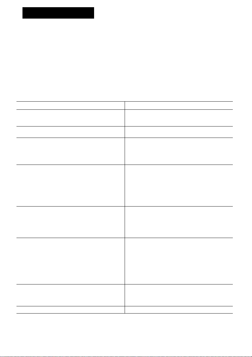
3 UNPACK THERMOSTAT
NOTE: Illustrations show thermostat models that have
conventional recovery from heating setback (except
when noted}.
□
Handle new thermostat carefully; rough handling
may interfere with its accuracy. Before unpacking, refer
may
to Fig. 1.
to Fi
□
Remove and discard shipping wrap. IMPORTANT;
Save package of screws, instructions, and spare pro
gram pins and ramp recovery segments (T8185R only)
for homeowner.
□ Remove thermostat cover by lifting from bottom.
Set aside cover until called for iater.
□ Carefully remove material protecting mercury
switch bulb (a).
□ Loosen 2 captive mounting screws and separate
wallplate (if provided} from back of thermostat base.
□
Run wires from heafing or heating/cooling equip
ment to new thermostat location.
This control requires an additional conductor to
the control transformer common; i.e., typical
2-wire heating system requires 3 wires be pulfed,
4-wire heating/cooling requires 5 wires.
IMPORTANT-
LIFT COVER
Fig. 1—Unpack thermostat.
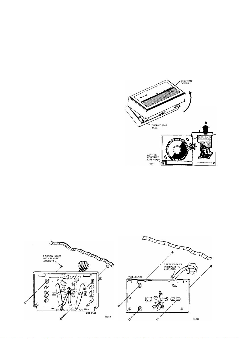
4 MOUNT WALLPLATE OR SUBBASE-
rH Hold wallplate or subbase in position on wall as
shown in Fig. 2.
EH Mark holes for anchors on the wall. Use spirit level
to make sure the wallplate or subbase will be level.
□ Drill 3/16 in. holes and gently tap anchors into
holes until flush with the wall.
E H
Pull wires through large wiring hole in subbase.
Fig. 2—Mounting wallplate or subbase to wall.
E H
Loosely fasten the wallplate or subbase to the wall
with the 3 screws.
EH
Carefully level the wallplate or subbase (Fig. 3)
and firmly tighten screws.
E H
For mounting on horizontai or vertical outlet box,
see instructions packed with optional Cover Plate
Assembly, Part No. 193121A.
2
Page 3

Fig. 3—Leveling methods for wallplate or subbase.
5 WIRE WALLPLATE OR SUBBASE
Follow the Instructions provided by the heating or
heating/coollng equipment manufacturer. If not available, refer to TYPICAL WIRING DIAGRAMS at end of
this publication,
NOTE: Aii wiring must comply with local electrical
codes and ordinances.
FOR WALLPLATE (Heating-Only System)
□ Refer to Fig. 4 and strip thermostat wire insulation
as necessary.
Q Connect wires to R, W, and C terminals. Firmly
tighten screws. The timer is powered by the system’s
low voltage transformer. NOTE: An unmarked fourth
terminal is provided for 3-wire [series 20} primary
controls (Fig, 11).
n Push excess wire back into wall.
□ Plug hole in wall with nonhardening caulk, putty,
or nonflammable insulation to prevent drafts from affect
ing thermostat operation.
FOR SUBBASE (Heating/Cooling Systems)
ED Refer to Fig. 4 and strip thermostat wire insulation
as necessary.
□ Connect the wires to corresponding terminals on
the subbase.
If labels do not agree with your new subbase—
—Refer to Table 2 or Figs. 12-15.
—Determine correct hookup from the listed control
function and the equipment control circuit.
The timer is powered by the system's low voltage
transformer. 24 Vac must be maintained across termi
nals R and C.
TABLE 2—TERMINAL DESIGNATIONS
SUBBASE
TERMINAL CONTROL FUNCTION
R Control transformer power.
W
G
□
Push excess wire back into wall.
Heating control circuit.
Y Cooling control circuit jumper to W
for heat pump compressor control}.
Fan control circuit.
Timer control (transformer common).
C
0 Changeover or reversing valve, made
continuously in cool.
Changeover or reversing valve made
B
continuously In heat
□
Piug hole in wall with nonhardening caulk, putty,
or nonflammable insulation to prevent drafts from affect
ing thermostat operation.
Page 4

6 MOUNT THE THERMOSTAT—-----------------
D Note the tabs on the top inside edge of the ther
mostat base. These fit the slots molded into the top of
the wailplate or subbase.
n Hang thermostat base on wailplate or subbase.
7 SET HEAT ANTICIPATOR----------------------
n Make sure you know the current draw (anticipator
setting] for your system. This information can be found
printed on the primary control at the furnace or on the
furnace output/listing label. However, it is good in
stallation practice to physically test the heating primary
current draw before setting the heat anticipator. This is
done by connecting the R and W terminals through a
suitable meter (0-5 A), or with thermostat wire held
through a clamp on meter using multiple loops to mag
nify the field (ten [oops are typically used so meter read
! I Insert the two captive mounting screws located in
the bottom corners of the base (Fig. 5).
Q Firmly tighten screws.
ing can be divided by ten). Physical measurement is
urged, as modern HVAC equipment typically incor
porates multiple control circuit loads, and accurate
anticipator setting prevents poor control and callbacks.
Move heat anticipator lever to match the current
□
draw (Fig. 6), except in single-stage heat pump sys
tems. In these systems, set the anticipator at 1.4 times
the actual current draw to reduce the cycling rate.
SHOWS
ANTICIPATOflSETTIKG
ZONE VALVE
anticipator
5CALEPLATE
ANTICIPATOR
SETTING
LEVER
TYPICAL GAS VALVE
Fig. 6—Setting heat anticipator.
OIL BURNER CONTROL
SHOWS
ANTICfPATOn
SHOWS
ANTICIPATOR
SETTfNG
Page 5

8 SET TIMER
----
-------------------------------------
iZH Adjust the timer by moving the knob in clockwise
direction. Do NOT reverse the knob.
Fig. 7—Set timer on models with conventional recovery.
9
ATTACH THERMOSTAT COVER-
O Make sure the packing inserts in the thermostat
base have been removed.
Place the two tabs on upper edge of Cover into
mounting slots in thermostat base (Fig. 9).
Swing cover downward until it engages catch at
□
bottom of base. If locking cover is used, tighten the
recessed hex head retaining screw at bottom of cover.
EH
Install spare program pins, ramp recovery seg
ments, if provided, in storage area under front lift-up
cover.
□ When time is correctly set, the Time Indicator
Arrow (Figs. 7 and 8) must point to the corresponding
daytime (light) or nighttime (dark) portion of the program
dial.
Fig. 8—Set timer on model (T81SSR) with ramp
recovery.
Fig. 9—Attach cover.
10 SET TEMPERATURE CONTROL LEVERS ■
El i
The two levers on top of thermostat control the
low and high temperatures for energy savings and com
fort control (Fig. 10). The lever on the left (blue mark)
controls the lower temperature. The lever on the right
(red mark) controls the higher temperature.
E EI
We recommend pushing the levers together at an
appropriate temperature for either heat or cool until the
occupant programs the thermostat and makes final
temperature selections.
11 SET SUBBASE SWITCHES
□ The subbase system switch controls system oper
ation as follows.
EMERGENCY HEAT (Q682L only)—The emergency
heat relay is energized. The cooling system is off
and the compressor is de-energized. Emergency
heat equipment is controlled by the thermostat
HEAT—Heating system is controlled by the thermo
stat Cooling system is off.
COOL—Cooling system is controlled by the ther
mostat Heating system is off.
OFF—Both the heating and cooling systems are off.
If the fan switch is at the AUTO position, the fan is
also off.
------------------
The subbase fan switch controls fan operation as
□
follows,
ON—Fan operates continuously.
AUTO—Fan operates with cooling equipment as con
trolled by the thermostat In electric heat systems
and in heat pump systems, the fan is controlled
by the thermostat during heating also.
□
To switch positions, use thumb or index finger to
slide lever to desired position. Switch lever must stop in
the detent over desired function indicator mark for
proper circuit operation.
Page 6

12 CHECK OUT THERMOSTAT OPERATION'
Do NOT check operation by shorting across ter
minais of relay or valve coil; this will burn out the
thermostat heat anticipator.
HEATING-ONLY SYSTEM
HU
Turn on power to the furnace.
[Z] Push both temperature setting levers together at
least 5 F [3 C] above room temperature. The main
burner should come on. The fan will start when the fur
nace heats up.
□ Move both levers 5 F [3 C] below room tempera
ture. The burner should shut off.
Q Operate the entire heating system at least one
oompíete cycle.
D
IF THERMOSTAT FAILS ANY TEST, REFER TO
TROUBLESHOOTING GUIDE IN THE OWNER'S
MANUAL.
□ Reset both temperature setting levers to desired
temperatures.
HEATING/COOLING SYSTEM
n Turn on power to the furnace and cooling system.
n Place the system switch lever at HEAT and fan
switch lever at AUTO.
[m Push both temperature setting levers together at
least 5 F [3 C] above room temperature. The main
burner should come on. The fan will start when the fur
nace heats up. (If central electric heat system, fan starts
immediately.)
Move both levers 5 F [3 C] below room tempera
□CAUTIONS
ture. The burner should shut off.
□
Place the system switch lever at COOL and the
fan switch lever at AUTO. The cooling equipment should
operate, and the fan will start. Allow for any time delay
that may be built into the compressor control circuit.
NOTE: To avoid compressor damage, do not operate
the system if outdoor temperature is below 50 F
[10 0]. Refer to manufacturer’s recommendations.
□ Move both temperature setting levers together at
least 5 F [3 C] above room temperature. The cooling
equipment should shut off.
Place the fan switch at ON. The fan should run
□
continuously with the system switch in any position.
HH Place the system switch at OFF. Move both
temperature setting levers to various positions. The
heating and cooling systems should not operate.
Operate the entire system for at least one com
□
plete cycle with the system switch at COOL and one
complete cycle with the switch at HEAT.
D IF THERMOSTAT FAILS ANY TEST, REFER TO
TROUBLESHOOTING GUIDE IN THE OWNER'S
MANUAL
Reset both temperature setting levers to desired
□
temperatures.
LEAVE OWNER’S MANUAL, ASSISTANCE INFORMA
TION, AND REPLY CARD IN A CONVENIENT PLACE
FOR THE BUILDING OCCUPANT OR PROVIDE WITH
OTHER APPLIANCE MANUALS.
TYPICAL WIRING DIAGRAMS
Follow the hookup diagram supplied with your heat
ing or heating/cooling equipment. If not available, use
the following diagrams as a guide.
REMEMBER: Your wiring must follow local electrical
codes and ordinances.
------------------
THERMOSTAT
Ai
Fig. 11 —Hookup showing a typical 24 V, gas heating
control system.
Page 7

A
Fig. 12—Hookup showing a typical heating/cooling control system.
THERMOSTAT
Ae
Fig. 13— Hookup showing a typical electric heating/mechanical cooling control system. Thermostat controls fan on
both heat and cool.
Page 8

/1\ POWER SUPPLY, PROVIDE DISCONNECT MEANS AND OVERLOAD PRO
Af
TECTION AS REQUIRED,
/z\ CONNECT VALVE TO TERMINAL O FOR POWER ON COOLING OR TO
TERMINAL B FOR POWER ON HEATING,
Fig. 14—Hookup showing a typicai single-stage heat pump control system.
TO SET ANTICIPATOR AT CORRECT RATING-MEASURE COMPRESSOR
A
RELAY CURRENT ON R WIRE WITH FAN SWITCH IN AUTO POSITION.
SET ANTICIPATOR AT 140 PERCENT OF CURRENT DRAW.
THERMOSTAT
Fig, 15—Hookup showing a typical 2-stage heating/l-stage cooling heat pump control system.
Honeywel! Inc.
1885 Douglas Drive N.
Golden Valley, MN 55422’'4386
Inliernational Sales Offices in all principal cities of the world. Manufacturing in
Australia, Canada, Finland, France, Germany, Japan, Mexico, Netherlands,
Spain, Taiwan, United Kingdom, U.S,A.
PRINTED iN U,S.A.
OLAUTVlSKn'
 Loading...