

Page 1
XNX
● Table of Contents
● Safety and Information
● Introduction
● Specications
● Control Drawings
● HART
Protocol
Technical
Manual
● Installation and Operation
● Calibration
● Maintenance
● Warnings/Faults
● Modbus Protocol
● Warranty
● Index
Page 2

This page is intentionally left blank
Page 3

XNX Universal Transmitter
TOC
Table of Contents
Safety and Information ���������������������������������������������������������������������5
Warnings�������������������������������������������������������������������������������������6
Hazardous Location Installation Requirements �������������������������8
Special Conditions for Safe Use �������������������������������������������������8
Cautions �������������������������������������������������������������������������������������8
Notes ������������������������������������������������������������������������������������������8
Information ����������������������������������������������������������������������������������9
Contacting Honeywell Analytics ��������������������������������������������������9
Revision History ��������������������������������������������������������������������������9
Introduction �������������������������������������������������������������������������������������10
Product Description �����������������������������������������������������������������11
The Transmitter �������������������������������������������������������������������11
20 mA/HART Output �����������������������������������������������������������12
Communications �����������������������������������������������������������������12
Certifications �����������������������������������������������������������������������12
Patents ��������������������������������������������������������������������������������13
Glossary �����������������������������������������������������������������������������13
Product Overview ���������������������������������������������������������������������14
Enclosure ����������������������������������������������������������������������������14
Cover ����������������������������������������������������������������������������������15
POD �����������������������������������������������������������������������������������15
Options �������������������������������������������������������������������������������������16
Local HART �����������������������������������������������������������������������16
Relays ���������������������������������������������������������������������������������16
Modbus ������������������������������������������������������������������������������17
FOUNDATION Fieldbus ������������������������������������������������������17
Accessories ������������������������������������������������������������������������17
The Front Panel ������������������������������������������������������������������������20
Controls and Navigation �����������������������������������������������������21
The General Status Screen ������������������������������������������������21
Entering the Menu ��������������������������������������������������������������22
Displaying Transmitter Information ��������������������������������������23
Main Menu ��������������������������������������������������������������������������������24
Menu Navigation �����������������������������������������������������������������������25
Installation and Operation ���������������������������������������������������������������29
Sensor Mounting and Location �������������������������������������������������30
Mounting the T ransmitter ����������������������������������������������������30
Wiring the Transmitter ���������������������������������������������������������32
General Wiring Considerations �������������������������������������������33
Loading �������������������������������������������������������������������������������33
Isolation ������������������������������������������������������������������������������33
Circuit Protection ����������������������������������������������������������������33
Distance Considerations for Installation������������������������������33
Single Transmitter ���������������������������������������������������������������34
Multiple Transmitters Connected to a Single Power Source 34
Multiple Transmitters Connected in a “Daisy-Chain”
Configuration ����������������������������������������������������������������������34
Power Source Selection ������������������������������������������������������35
Wire Selection ���������������������������������������������������������������������35
Single Transmitter Distances ����������������������������������������������36
Daisy-Chained Transmitter Distances ���������������������������������36
POD Connections ���������������������������������������������������������������38
4-20mA Output, Common Connections, and Power ����������39
Settings ������������������������������������������������������������������������������39
FOUNDATION Fieldbus Wiring �������������������������������������������41
Terminal Block Connections �����������������������������������������������41
Table of Contents
1
Page 4
XNX Universal Transmitter
✓
X
?
?
?
Table of Contents
EC Personality Wiring ���������������������������������������������������������42
Electrochemical Sensor Installation ������������������������������������43
EC Sensor Remote Mounting Kit ����������������������������������������44
mV Personality Wiring ���������������������������������������������������������46
mV Remote Sensor Mounting ���������������������������������������������47
IR Personality Wiring ����������������������������������������������������������49
Searchpoint Optima Plus/Searchline Excel Connections ���50
Connecting Generic mA Devices ����������������������������������������50
Attaching the Searchpoint Optima Plus to the Transmitter �53
Searchline Excel/Searchpoint Optima Plus Remote
Installation ���������������������������������������������������������������������������53
Searchpoint Optima Plus/Searchline Excel Wiring �������������54
Options �������������������������������������������������������������������������������������56
Local HART Interface ����������������������������������������������������������56
Point-to-Point Mode ������������������������������������������������������������56
Multidrop Mode �������������������������������������������������������������������57
Cable Length ����������������������������������������������������������������������58
Relays ���������������������������������������������������������������������������������58
Modbus ������������������������������������������������������������������������������59
FOUNDATION Fieldbus ������������������������������������������������������60
Powering the Transmitter the First Time ������������������������������61
IR Units Configured for Searchline Excel ���������������������������62
Remote Calibration of MPD Sensors ����������������������������������63
Configuring the Transmitter �������������������������������������������������������63
Configure Menu ��������������������������������������������������������������64
Select Language �������������������������������������������������������������64
Set Date and Time ���������������������������������������������������������65
Set mV Sensor Type �������������������������������������������������������66
Set mA Sensor Type �������������������������������������������������������67
Gas Selection �������������������������������������������������������������������67
Changing the Gas or Units Name ���������������������������������������69
Gas Selections and Alarm Limits Based on mV Sensor Type
��������������������������������������������������������������������������������������������69
Range and Alarms ����������������������������������������������������������74
Latching/Non-Latching Alarms ���������������������������������������77
Set Units ��������������������������������������������������������������������������78
mA Levels �����������������������������������������������������������������������79
Calibration Interval ����������������������������������������������������������79
Accept New Sensor Type ������������������������������������������������80
Beam Block Options �����������������������������������������������������81
Path Length ��������������������������������������������������������������������82
Unit ID �����������������������������������������������������������������������������83
Relay Options �����������������������������������������������������������������84
Fieldbus Options �����������������������������������������������������������85
Configure Security �����������������������������������������������������������86
Verifying the Configuration��������������������������������������������������������87
Test Menu ������������������������������������������������������������������������87
Inhibit ������������������������������������������������������������������������������87
Force Relays ������������������������������������������������������������������89
Alarm/Fault Simulation ���������������������������������������������������89
Information Menu ������������������������������������������������������������91
Alarm/Fault Status ����������������������������������������������������������91
Transmitter Data �������������������������������������������������������������91
Transmitter Status ����������������������������������������������������������92
Sensor Data ��������������������������������������������������������������������92
Sensor Status �����������������������������������������������������������������93
Table of Contents
2
Page 5
XNX Universal Transmitter
?
Table of Contents
Gas Data ��������������������������������������������������������������������������93
Range/Alarm Settings�����������������������������������������������������94
mA Level Settings �����������������������������������������������������������94
Fieldbus Settings �����������������������������������������������������������95
Relay Data ����������������������������������������������������������������������95
Event History ����������������������������������������������������������������97
Calibration ������������������������������������������������������������������������������������100
Gas Calibration Menu���������������������������������������������������101
Zero and Span Calibration for EC/mV Sensors and
Searchpoint Optima ����������������������������������������������������������102
Using the Calibration Cup �������������������������������������������������105
Zero and Span Calibration of EC Sensors ������������������������105
Zero and Span Calibration for MPD Sensors ��������������������110
EC Sensor Operational Life ����������������������������������������������113
Functional Gas T esting (Bump T esting) ����������������������������113
Calibrate mA Output ���������������������������������������������������114
Align Excel (Searchline Excel) �������������������������������������115
Soft Reset ��������������������������������������������������������������������115
Maintenance ���������������������������������������������������������������������������������116
MPD Sensor Cartridge Replacement �������������������������������117
EC Sensor Cartridge and Cell Replacement ��������������������118
Warnings and Faults ���������������������������������������������������������������������120
Warning Messages �����������������������������������������������������������121
Notes ��������������������������������������������������������������������������������125
Fault Messages �����������������������������������������������������������������126
Notes ��������������������������������������������������������������������������������133
Informational Messages ����������������������������������������������������135
Specifications �������������������������������������������������������������������������������137
Product Specifications ������������������������������������������������������������138
SENSOR DATA �����������������������������������������������������������������140
Operating and Storage Conditions for Performance Tested
EC Cartridges �������������������������������������������������������������������140
Detectable Gases and Performance ���������������������������������������141
EC Sensor Performance Data, Factory Mutual Verified ����������142
EC Sensor Performance Data, DEKRA EXAM Verified ����������143
Other EC Sensors ������������������������������������������������������������������144
Footnotes (see table on previous page): ��������������������������145
Notes (see table on previous page): ���������������������������������145
EC Sensor Cross-sensitivity ���������������������������������������������������146
Notes ��������������������������������������������������������������������������������153
MPD Sensor Performance Data ���������������������������������������������154
Notes �������������������154
EN60079-29-1 Performance Approved Gases for mV Sensor
Types ��������������������������������������������������������������������������������������155
Notes �������������������155
Other Sensor Performance Data ��������������������������������������������155
Certifications by Part Number Series �������������������������������������156
Notes �������������������157
Certification Labels ����������������������������������������������������161
Product Identification �������������������������������������������������������������163
EC Replacement Sensors ������������������������������������������������������164
EC Replacement Cells �����������������������������������������������������������165
MPD (Multi Purpose Detector) ������������������������������������������������166
Accessories/Spares ����������������������������������������������������������������167
EC Declaration of Conformity �������������������������������������������������171
�����������������������������������������������������������������������������������������������171
Table of Contents
3
Page 6

XNX Universal Transmitter
Table of Contents
Control Drawings ��������������������������������������������������������������������������172
XNX UL/CSA/FM/ATEX/IECEx/INMETRO/RUSSIA ���������������173
Remote Sensor Mount ������������������������������������������������������������177
HART Protocol ������������������������������������������������������������������������������178
HART Interface �����������������������������������������������������������������������179
HART Sink, Source, and Isolated Wiring ��������������������������������182
DevComm PC-based HART Interface ������������������������������������185
Functions ��������������������������������������������������������������������������������186
Configuration Summary ����������������������������������������������������186
Information Screens ����������������������������������������������������������187
Event History ��������������������������������������������������������������������187
Test �����������������������������������������������������������������������������������187
Calibration �������������������������������������������������������������������������188
Configuration ��������������������������������������������������������������������188
Handheld Online Menus ���������������������������������������������������������189
Modbus Protocol ���������������������������������������������������������������������������191
Modbus and the XNX transmitter ��������������������������������������������192
Modbus Registers �������������������������������������������������������������������194
Warranty ���������������������������������������������������������������������������������������198
Warranty Statement ����������������������������������������������������������������199
Warranty Conditions ���������������������������������������������������������199
Consumer Claims �������������������������������������������������������������199
Index ���������������������������������������������������������������������������������������������200
Table of Contents
4
Page 7

XNX Universal Transmitter
Safety and Information
Safety and Information
5
Page 8
XNX Universal Transmitter
WARNING
!
Read and understand this manual before installing, operating, or
maintaining the transmitter. Pay particular attention to these warnings and
cautions. All of the warnings and cautions shown here are repeated in the
appropriate sections of the manual.
• Warnings identify hazardous or unsafe practices which could result in severe injury
or death.
Warnings
• Installation must be in accordance with the recognized standards of the
appropriate authority in the country concerned.
• Any work on the interior of the detector must be conducted only by Honeywelltrained personnel
• Before carrying out any work, ensure that local regulations and site procedures
are followed. Appropriate standards must be followed to maintain the overall
certification of the sensor.
• To reduce the risk of ignition in hazardous atmospheres, disconnect the equipment
from the supply circuit before opening the sensor enclosure. Keep the assembly
tightly closed during operation. Conduit runs must have a seal fitting connected
within 18 inches (45 cm) of the enclosure.
• Never open the XNX enclosure under power unless the area is known to be nonhazardous.
• Do not use the XNX Universal Transmitter in oxygen-enriched atmospheres. In
oxygen-enriched atmospheres, the electrical safety is not guaranteed.
• The sensor must be earthed/grounded for intrinsic safety, electrical safety and to
limit the effects of radio frequency interference. Earth/ground points are provided
inside and outside the unit. EMI note for applications using shielded cable: Cable
shield must provide 90% coverage of the wiring. Cable shield terminations must
be made at the cable glands with suitable EMI type glands. Avoid terminating
cable shields at the Earth ground lug inside the XNX enclosure. In cases where
wiring is in pipe, a shielded cable is not required. The external terminal is only a
supplemental bonding connection where local authorities permit or require such a
connection.
• Take care when handling EC sensor cells as they may contain corrosive solutions.
Do not tamper or in any way disassemble the sensor cells. Do not expose to
temperatures outside the recommended range. Do not expose the sensor to
organic solvents or flammable liquids.
• At the end of their working lives, sensors must be disposed of in an
environmentally safe manner, in accordance with local waste management
requirements and environmental legislation. Alternatively, sensors may be securely
packaged, clearly marked for environmental disposal, and returned to Honeywell
Analytics. Do NOT incinerate sensors as they may emit toxic fumes.
• High off-scale readings may indicate an explosive concentration of gas.
• Verify all outputs, including display, after installation, after service events, and
periodically to ensure the safety and integrity of the system.
• Do not use the transmitter in oxygen-enriched atmospheres. Concentrations
displayed will be adversely affected by oxygen depletion.
• After changing parameters with a handheld device, verify that the parameter
settings are correct at the transmitter.
• The factory-set passcodes must be reset to prevent unauthorized access to the
transmitter’s menus.
• When the transmitter is equipped with the optional Remote Mount Kit, the remote
sensor must be securely mounted in a fixed position. The Remote Sensor kit is not
intended to be used as a handheld sensor.
Safety and Information
6
Page 9

XNX Universal Transmitter
• Enclosures of remotely mounted sensors contain aluminum. When installed in
Zone 1 locations, be careful to avoid ignition hazards due to impact or friction.
• Install the junction box according to local codes and manufacturer’s requirements.
• The enclosures of remotely mounted 705HT sensors contain aluminum. When
installed in Zone 1 locations, be careful to avoid ignition hazards due to impact or
friction.
• Power off the transmitter before changing S3 or S4. Failure to do this will
permanently damage the transmitter. Both switches must be set in either Source
or Sink prior to applying power.
• Do not set the minimum or maximum controller alarm levels at less than 10% or
greater than 90% of the full scale range of the sensor. CSA and FM agency limits
are 60% LEL or 0.6mg/m3.
• When configuring or communicating with the transmitter using the front panel
displays, resume monitoring by exiting all menus and returning to the General
Status menu manually. No time outs are invoked.
• When selecting a new target gas for units with a Searchpoint Optima Plus, the
sensor must be recalibrated.
• XNX Universal Transmitters carrying UL/CSA/FM approvals that are configured for
devices measuring %LEL will not allow adjustments to the full scale value. The
range is fixed at 100%.
• There is a potential loss of sensitivity during exposure to high concentrations
of H2S. Under these conditions, set the control unit to latch at overrange. In
standalone configuration, set alarms to latching. When resetting the overrange or
alarm, verify correct operation of the transmitter.
• Keep the passwords in a secure area to prevent unauthorized access to the
transmitter. If the passwords are lost, resetting the transmitter will require a
service technician.
• When the transmitter is placed in Inhibit Mode, alarms are silenced. This will
prevent an actual gas event from being reported. Inhibit Mode must be limited
to testing and maintenance only. Exit Inhibit Mode after testing or maintenance
activities.
• Honeywell recommends periodic bump tests (every 30 days or in accordance
with customer site procedures) to the sensor to insure proper operation and
compliance with the functional safety rating of the installation.
• Honeywell Analytics recommends bump testing of ClO2, Cl2, HF, and HCl sensors
frequently and in accordance with customer site procedures to ensure proper
operation and compliance with the functional safety rating of the installation.
• As some test gases are hazardous, exhaust the flow housing outlet to a safe area.
• Exposure to desensitizing or contaminating substances or concentrations causing
operation of any alarm may affect sensor sensitivity. Following such events, verify
sensor performance by performing a functional gas test (bump test).
• When servicing or replacing sensors, reduce the risk of ignition in hazardous
atmospheres by declassifying the area or disconnecting the equipment from the
supply circuit before opening the sensor enclosure. Keep the assembly tightly
closed during operation.
• Take appropriate precautions when using toxic, flammable, or pressurized
cylinders.
• XNX transmitter is SIL2 approved and please refer to XNX transmitter safety
manual (1998-0808) for the detail of SIL certificate.
ELECTROSTATIC DISCHARGE
To minimize the risk of electrostatic discharge:
• Ground the transmitter adequately
• Install the transmitter in a manner that will prevent accidental electrostatic
discharges, e.g. ensure that objects do not rub against the housing etc.
• Clean the enclosure with a damp cloth when necessary
Safety and Information
7
Page 10
XNX Universal Transmitter
CAUTION
!
NOTE
Hazardous Location Installation Requirements
• Read and understand this manual prior to installation and use.
• Use only certified cable glands for installation.
• Shielded armored cable is required for CE compliance.
• To reduce the risk of ignition in hazardous atmospheres, conduit runs must have a
pour gland installed within 18 inches (45 cm) of the enclosure.
• All ¾ inch NPT conduit, stopping plugs, and adapters must be installed with 5¼
threads (minimum) engaged to maintain the explosion-proof rating.
• The XNX cover assembly must be fully seated to the enclosure (7 threads
minimum) to maintain the explosion-proof rating.
• Use only the supplied stopping plugs (Honeywell part number 1226-0258) with the
XNX Universal Transmitter.
• For units fitted with the optional relay module: relay contact ratings are 250 VAC
5A, 24 VDC 5A resistive loads only.
• Use copper conductors only. Tighten terminal block screws to 4.5 lb/in (max).
• For XNX-UT**-***** transmitters, refer to XNX control drawing 1226E0402.
Special Conditions for Safe Use
• The following applies to the HART Barrier intrinsically safe circuits: For installations
in which both the Ci and Li of the intrinsically safe apparatus exceed 1% of the Co
and Lo parameters of the associated apparatus (excluding the cable), then 50% of
Co and Lo parameters are applicable and shall not be exceeded, i.e., the Ci of the
device plus the C of the cable must be less than or equal to 50% of the Co of the
associated apparatus, and the Li of the device plus the L of the cable must be less
than or equal to 50% of the Lo of the associated apparatus.
• For circuits connected to the EC barrier in which the capacitance and inductance
exceed 1% of the permitted values, the maximum permitted capacitance is limited
to 600 nF for group IIC and 1uF for group IIIC.
• The connection to the HART circuit shall be rated a minimum of IP 6X.
• Delays resulting from transmission errors between sensor and transmitter extend
response times T90 by more than one-third. The period until fault indication is 10
seconds.
• The HART interface is subject of this EC-type examination certificate only for the
purpose of configuration and maintenance. The options “Modbus interface” and
“FOUNDATION Fieldbus interface” are not subject of this EC-type examination
certificate.
• Long-term exposure (>20 minutes) to concentrations exceeding the full-scale
range of the H
value may then decrease even though high levels of toxic gas are still present. If
such conditions can occur, set the control unit to latch at overrange. In standalone
operation, set alarms to latching. When resetting the overrange or alarm, verify the
correct operation of the transmitter. Before re-calibrating the transmitter, verify the
absence of gas.
• The flameproof joints are not intended to be repaired.
S sensor Type 2 can cause it to lose sensitivity. The measured
2
Cautions
Caution messages address situaltions that could result in damage to the
transmitter or sensors.
Notes
!
Notes relate helpful information.
Waste Electrical and Electronic Equipment (WEEE) Directive
This symbol indicates that the product must NOT be disposed of as general
industrial or domestic waste. This product should be disposed of through
suitable WEEE disposal facilities. For more information about disposal of this
product, contact your local authority, distributor or the manufacturer.
Safety and Information
8
Page 11
XNX Universal Transmitter
Information
Honeywell Analytics assumes no responsibility for equipment that is not
installed and used following the procedures in the Technical Manual.
Ensure that the appropriate equipment has been installed. If in doubt,
contact Honeywell Analytics.
Honeywell Analytics assumes no responsibility for errors or omissions in
this document or the consequences of those errors or omissions. Contact
Honeywell Analytics with corrections. Honeywell Analytics reserves the
right to revise this document without notice. Contact the local distributor or
Honeywell Analytics if additional information is needed.
XNX® is a registered trademark of Honeywell International.
TM
Reex
is a trademark of Honeywell International.
HART® is a registered trademark of the HART Communication
Foundation.
Modbus® is a registered trademark of Schneider Automation Inc.
FOUNDATIONTM is a trademark of Fieldbus Foundation.
Unistrut® is a registered trademark of Unistrut Corporation.
Windows® is a registered trademark of Microsoft Corporation.
Revision History
Revision Comment Date
Rev 13 ECO 9425 Oct 2018
Rev 14 ECO 9443 Jan 2019
Rev 15 ECO 2019-4777 Sep 2019
Contacting Honeywell Analytics
www.honeywellanalytics.com
Europe, Middle East, Africa, India
Life Safety Distribution GmbH
Javastrasse 2
8604 Hegnau
Switzerland
Tel: +41 (0)44 943 4300
Fax: +41 (0)44 943 4398
India Tel: +91 124 4752700
gasdetection@honeywell.com
Americas
Honeywell Analytics Inc.
405 Barclay Blvd.
Lincolnshire, IL 60069
USA
Tel: +1 847 955 8200
Toll free: +1 800 538 0363
Fax: +1 847 955 8210
detectgas@honeywell.com
Asia Pacific
Honeywell Analytics Asia Pacific
7F SangAm IT Tower, 434 Worldcup Buk-ro,
Mapo-gu, Seoul 03922
Korea
Tel: +82-2-69090300
Fax: +82-2-69090328
analytics.ap@honeywell.com
Technical Services
EMEA: HAexpert@honeywell.com
US: HA.us.service@honeywell.com
Safety and Information
9
Page 12

XNX Universal Transmitter
Introduction
XNX Universal Transmitter Technical Manual
10
Page 13
XNX Universal Transmitter
e
r
ype
y
ppo
o
s
Product Description
The Transmitter
The transmitter is a comprehensive gas detection system
designed to operate in hazardous locations
sensor technologies –catalytic bead, electrochemical (EC),
or infrared (IR)– to detect toxic gases, ammable gases, and
oxygen depletion gas hazards. Each technology has a dedicated
personality board.
Catalytic bead technology is used with the mV personality
board. Catalytic bead sensors respond to a wide variety of
combustibles so are typically used for ammable gas detection.
Electrochemical technology is used with the electrochemical
board. EC sensors measure toxic gases in low concentrations.
The EC sensors employ the patented Reex™ cell fault
diagnosis routine. Reex checks for cell presence, cell dry-out,
and cell open or short circuit. Reex is automatically initiated
by the transmitter at eight-hour intervals. It is also initiated on
power up or sensor exchange. In the event of a cell failing this
test, a sensor fault code is displayed. Reex diagnostics occur in
the rst minutes of the power up sequence.
Infrared technology is used with the IR board. IR sensors
optically absorb gases that fall into the infrared spectrum.
For additional information about any of these sensor types, refer
to the applicable data sheet for the supported sensor in Figure 1.
The transmitter also allows for an optional communication
board. There are three types of boards: relay, Modbus
1
There are three main types of gas hazards: ammable, toxic, and asphyxiant. A am-
mable gas hazard is one in which there is a risk of re and/or explosion (e.g., a situation
in which a gas such as methane, butane, or propane is present). A toxic gas hazard is
one in which there is a risk of poisoning (e.g., a gas such as carbon monoxide, hydrogen
sulde, or chlorine is present). An asphyxiant hazard would include a risk of suffocation
through oxygen deciency. (Oxygen can be consumed or displaced by another gas.)
Introduction
1
and utilize multiple
®
, or
FOUNDATIONTM Fieldbus. See the Communications section for
additional information.
XNX Universal Transmitter
Searchline Excel
Searchpoint Optima Plus
705
705HT
CI
H
2
CIO
CO
F
2
Personality Sensor Type Supported Sensors
rsonality Senso
NH
2
NO
H2S
2
NO
HF
EtO
HCN
HCI
O
3
2
PH
3
SO
2
2
O
3
Su
Sensepoint
Sensepoint HT
ted Sens
Multi-Purpose
Detector (MPD)
Catalytic Bead
Infrared Flammable
Infrared Methane/CO
IR Point and Open-Path Infrared Searchpoint Optima Plus, Searchline Excel
mV Flammable and Toxic
XNX EC Toxic and O
Sensing
2
705, 705HT, Sensepoint, Sensepoint HT, MPD
(Catalytic Bead Flammable, IR Flammable and IR CO
Electrochemical sensors, with Hot Swap, pre-calibrated
through Intrinsically Safe (IS) barrier
.
Figure 1. XNX Universal Transmitter and supported sensing technologies
The transmitter relies on 4-20mA output, refreshed at least every
two seconds (once per second is typical), in which the output is
proportional to the gas concentration.
11
2
)
2
Page 14
XNX Universal Transmitter
20 mA/HART Output
All XNX Transmitters provide a 20mA Current Loop with HART
Communication which can be user congured for Sink, Source
(3-Wire) or Isolated (4-Wire) electrical interface based on
installation requirements.
The 20mA current loop output provides an analog indication of
special states, a proportional output to gas concentration and
overrange indication as shown in the table below. In the event of
a simultaneous alarm and fault, an alarm condition will always
override fault or warning state.
Output Description* Notes
1.0 mA Fault
Warm-up
2.0 mA
3.0 mA Warning
4-20 mA Gas Concentration
21 mA Overrange
*Alarm conditions always take priority over faults and warnings.
Inhibit
Bump Test
Calibration
Special
State
Indication
HART Protocol provides communications with the transmitter
from a remote control system for Conguration, Status, and
Diagnostics. (See the HART Protocol section for additional
information)
Communications
The XNX® Universal Transmitter is registered with the HART®
Communication Foundation. The transmitter
features HART over 4-20mA as standard.
Introduction
Additional optional communication interfaces are available:
relay communication, Modbus, or FOUNDATION Fieldbus.
Each communication option has a dedicated option board. For
additional information, refer to the Options section.
Certifications
XNX-UT**-****** Versions are UL and CSA listed for installation in
Class I, Division 1, Groups A, B, C and D Hazardous Locations.
FM Approvals evaluation includes Class I, Zone 1, Group IIC,
as well as performance tests for specic sensor/transmitter
combinations. The CSA or FM certication does not cover daisychained XNX combustible gas transmitters, the use of HART,
Modbus, or FOUNDATION Fieldbus protocols for combustible
gas performance. HART, Modbus, or FOUNDATION Fieldbus
protocols can be used only for data collection or record keeping
with regards to combustible gas. The EC cartridge
remote mount kit are UL classied to Canandian and US
standards.
XNX-AM **-***** versions are certied to comply with the
European Community ATEX Directive and the prescribed
protection methods for installation in potentially explosive
atmospheres.
XNX-BT**-***** versions are UL listed and INMETRO approved for
compliance with both U.S. and Brazilian standards.
See the Sensor Data section for additional information on
applicable approvals by part number and the Operating and
Storage Conditions for Performance Tested EC Sensors section
for marking.
2
“Cartridge” and “sensor” are used interchangeably in this document.
12
2
and EC
Page 15
XNX Universal Transmitter
Patents
Patents Applicable to the XNX Universal Transmitter
Patent
Number
6,123,818 Reflex patent Implemented in XNX
6,251,232 Reflex patent Implemented in XNX
6,351,982 Flammable sensor housing XNX accepts this sensor
6,395,230 Pellistor Sensor used in XNX
7,225,661 Gas calibration adapter Applicable to XNX
7,716,962 Method of gas calibration Used to calibrate XNX ECC cartridges
Description Application
Glossary
Term Description
bump test
ferrite bead a device that suppresses noise in a circuit
FOUNDATION Fieldbus
HART Protocol
intrinsic safety
IP rating
latching alarm an alarm that, once activated, must be manually reset
magnetic wand a small device used to change the transmitter’s settings
Modbus a digital communications protocol based on RS-485 topology
non-latching alarm
pellistor/bead an electronic device used to detect combustible gases
personality board
POD
span calibration
sticky gases gases that tend to coat the surfaces they contact
toxic gases
zero calibration
a brief exposure to a gas to verify that a detector is working;
also known as a functional test
an open architecture, digital, serial communication system
administered by the Fieldbus Foundation
Highway Addressable Remote Transducer Protocol; a bidirectional analog communication system developed by the
HART Communication Foundation
design parameters for the safe operation of electrical equipment in hazardous environments; commonly abbreviated IS
Ingress Protection; a system for describing a device’s protection against dry materials and liquids (e.g., IP66/67)
an alarm that automatically resets when the cause of the
alarm is removed
a component of the transmitter that allows its operation to
focus on different sensing technologies
Personality, Options, and Display; the group of components
including an XNX transmitter’s personality board, display, communication board, etc.
adjustment of a detector so that its scale corresponds to a gas
concentration range from 0% to 100%
gases that are poisonous to humans (refer to the gas’s Safety
Data Sheet for details)
adjustment of a detector so that its zero reading corresponds
to a test gas concentration of 0%
Introduction
13
Page 16
XNX Universal Transmitter
CAUTION
!
Product Overview
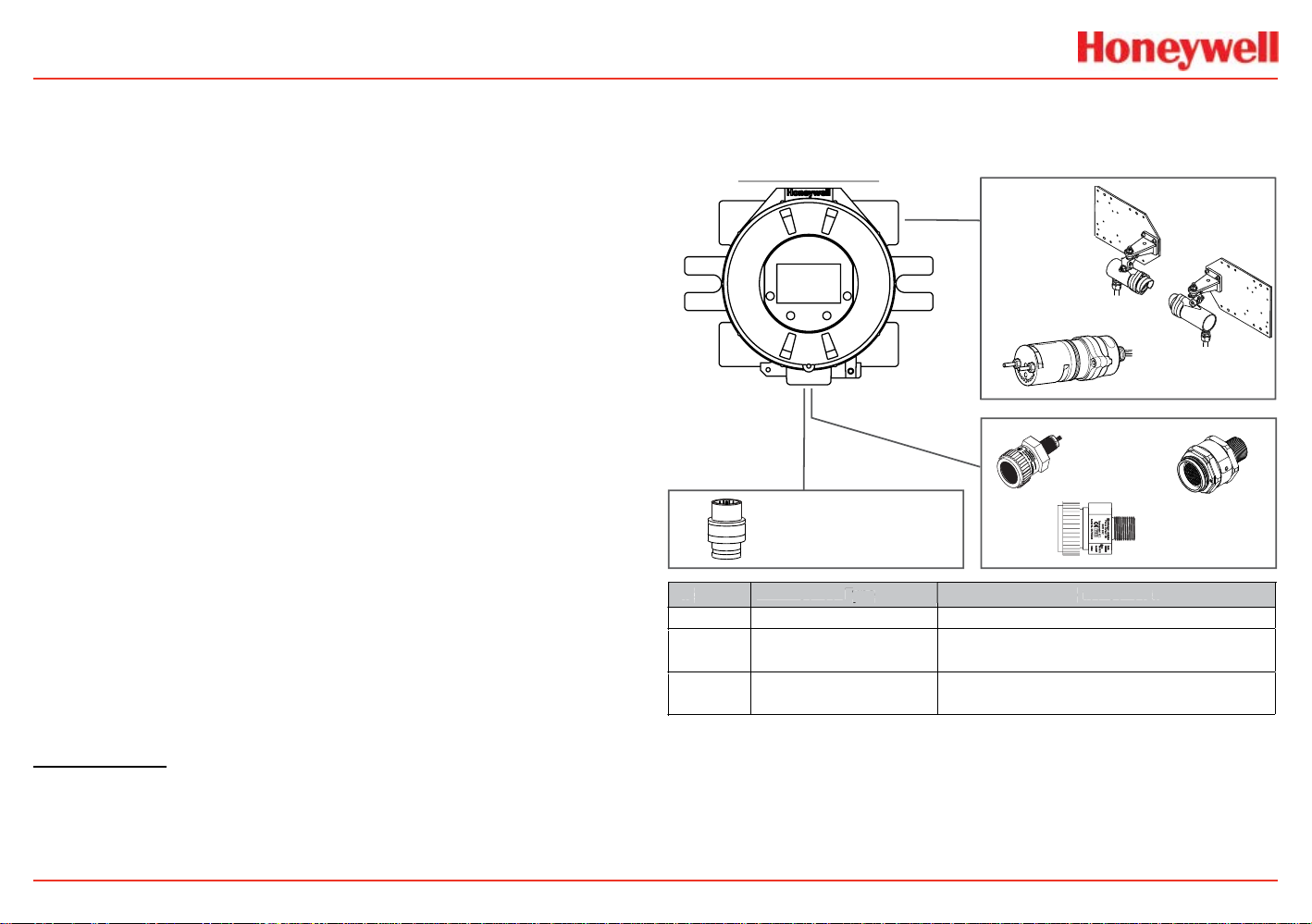
The transmitter is comprised of these main parts:
Figure 2. XNX exploded view
Enclosure
Available in either Stainless Steel or Aluminum, with 3/4” NPT
(UL/CSA or UL/ INMETRO) or M25 (ATEX/IECEx only) threaded
cable/conduit ports, the transmitter enclosure is explosionproof and suitable for use in -40°F to +149°F (-40°C to +65°C)
operating conditions. A 5-coat marine nishing process provides
the highest degree of corrosion protection. For more information
on performance specications, see the Specications section.
The enclosure is equipped with up to ve threaded cable/conduit
ports providing functional and exible congurations based on
sensor and option choices. See Cable/conduit port assingments
for port assignments and restrictions.
Stopping plugs (PN# 1226-0257 or 1226-0258) have been
provided to seal unused cable/conduit ports and have been
Agency evaluated/approved for use with the XNX enclosure only.
The number of stopping plugs varies among available
congurations.
Caution: The stopping plugs are for use only with the XNX transmitter. Do not use them
with any other device.
Mounting lugs integral to the enclosure allow easy installation
on a at surface or 2”-6” (50-150 mm) diameter pipe with the
optional Pipe Mount Kit or to ceilings with the Ceiling Mount
Bracket Kit.
Introduction
14
Page 17
XNX Universal Transmitter
Cover Lock Screw, requires a
2mm hex key (included)
Tempered Glass Window
Cover
NOTE
Cover
The transmitter cover is supplied in the identical material
specied for the enclosure.
Figure 3. XNX cover components
A tempered glass window requires the use of the supplied magnetic
wand/screwdriver to activate the four user interface switches
located on the front of the display module. This allows for non-
intrusive setup and operation.
A locking screw integrated into the cover provides positive
locking that can be loosened by using the supplied 2mm hex
key.
Figure 4. Magnetic wand/screwdriver
POD
The POD (Personality, Options, and Display) includes circuit
boards for the personality module, optional interfaces, and
display.
The personality module, or circuit board, determines the
transmitter behavior based on the sensor type attached to
the transmitter (electrochemical cell, catalytic bead sensor, or
infrared) and provides the necessary interface. Connection to the
attached sensor is made through the sensor connector.
The optional communication boards vary depending on the
option selected when ordered. Only one of the three available
interface options (relays, Modbus, or FOUNDATION Fieldbus)
can be attached to the transmitter.
!
Note: When attaching the cover or stopping plugs, coat the threads with a suitable antiseize compound to prevent corrosion.
Introduction
Figure 5. POD, exploded view
15
Page 18
XNX Universal Transmitter
NOTE
Options
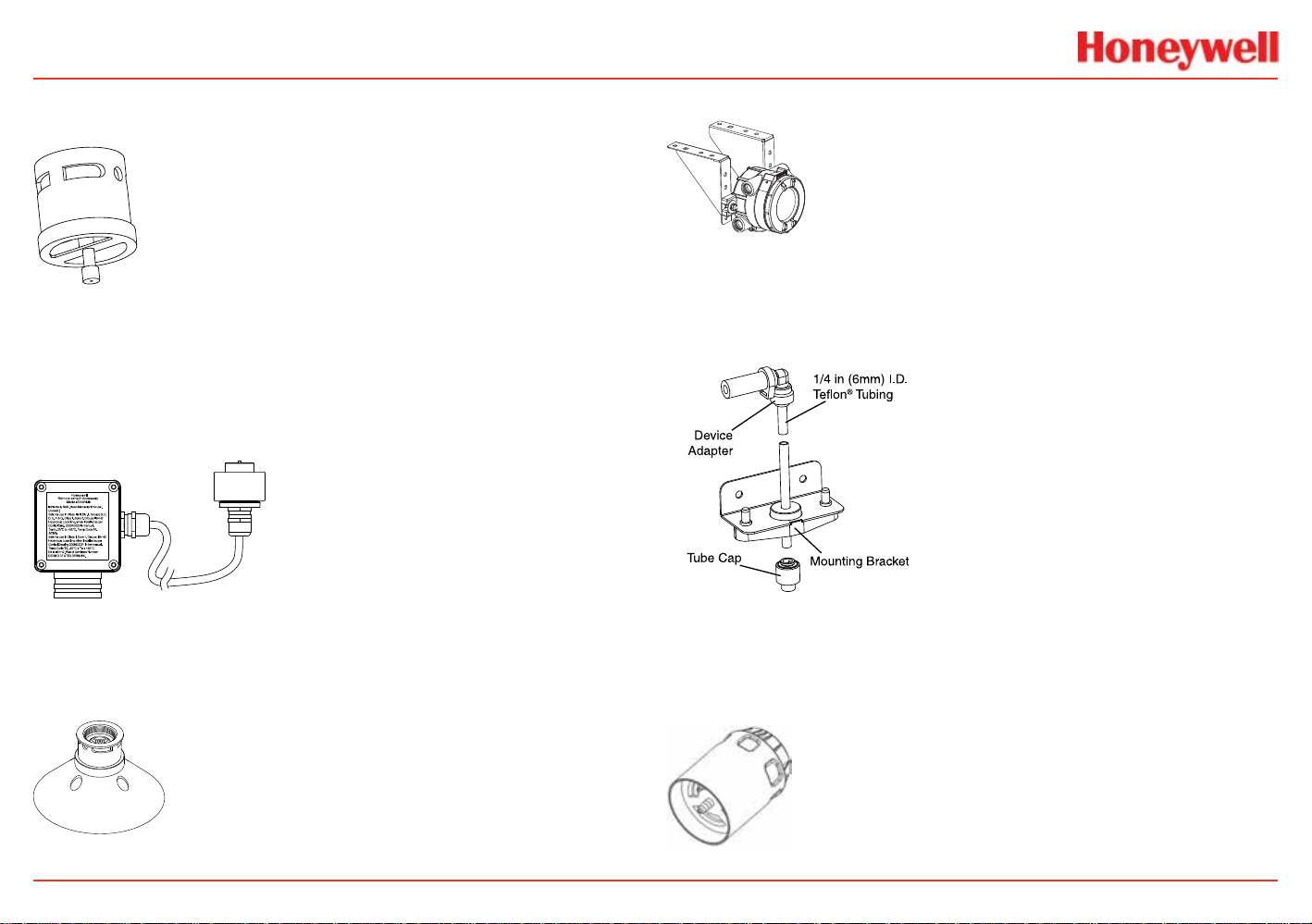
Local HART
Available with any sensor technology or personality, an external
access to the HART interface in the transmitter is provided.
An intrinsically safe (IS) barrier inside the transmitter gives
the user full control using a handheld eld communicator
for programming and conguration. The external interface is
installed in the lower left cable/conduit port of the transmitter
and is intrinsically safe. For more information, see the HART
Protocol section.
Figure 6. XNX Universal Transmitter with HART interface IS barrier
!
Note: POD options are either relay, Modbus, or FOUNDATION Fieldbus.
Relays
The relay option (XNX-Relay) provides 3 form “C” (SPDT)
normally open/normally closed (NO/NC) contacts for alarm and
fault indication. A remote reset input (TB4) is provided to silence
alarms. Momentarily closing the the circuit between the pins of
TB4 performs the same function as the Reset Alarms & Faults
command.
The remote reset switch (designated TB-4 and labeled “Remote
Reset SW”) is located on the relay option board. It provides
a remote hardware-based reset of faults and alarms to the
transmitter. In the event that direct access to the local and
®
HART
transmitter may be reset remotely using a momentary switch.
This will momentarily close the circuit between the two pins of
TB4, providing the same functionality as a Reset Alarms & Faults
command performed from the main screen of thelocal user or the
HART interfaces.
Relays are not available when the Modbus
Fieldbus options are installed.
The transmitter has three relays: relay 1 is for alarm level 1, relay 2
is for alarm level 2, and relay 3 is for faults and special states. Two
alarm levels can be set, allowing, for example, a level 1 alarm for
the immediate area when a certain gas concentration is detected
and a plant-wide level 2 alarm when a greater gas concentration is
detected.
The maximum refresh rate of the relays is 2 seconds. See the Set
Alarm Values section for more information.
interfaces is not possible, alarms and faults from an XNX
®
or FOUNDATION
Introduction
16
Page 19
XNX Universal Transmitter
NOTE
Modbus
The optional Modbus interface allows the transmitter to connect
to a bus of devices and transmit data to PLCs or controllers.
(For more information, see the Modbus
Connections to the transmitter are made through a pluggable
terminal block on the Modbus interface circuit board. Modbus
RTU protocol uses ASCII/Hex protocols for communication.
Protocol Manual).
FOUNDATION Fieldbus
FOUNDATION eldbus is a digital communication system which
supports several types of messages. Unlike many traditional
systems which require a set of wires for each device, multiple
FOUNDATION eldbus devices can be connected with a
single set of wires. FOUNDATION eldbus overcomes some
of the disadvantages of proprietary networks by providing a
standardized network for connecting systems and devices.
!
Note: FOUNDATION Fieldbus XNX transmitters require a separate power source and
cannot be powered via the bus.
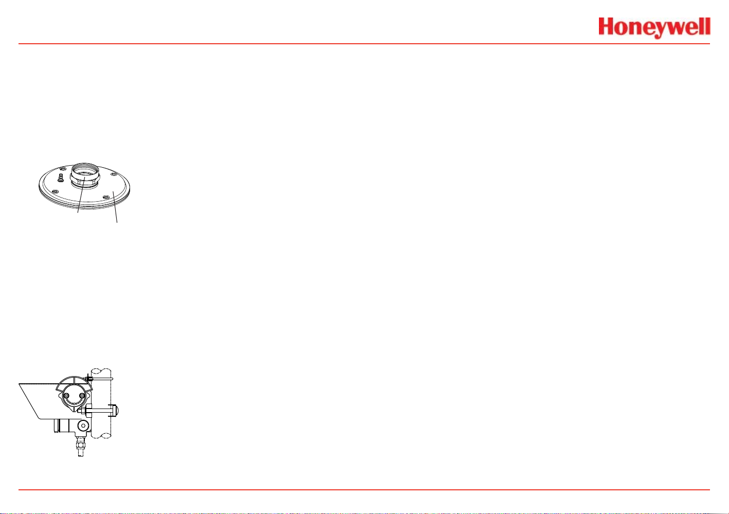
Accessories
Refer to the Accessories/Spares section for part numbers.
Pipe Mount Kit
The pipe mount kit allows the transmitter to be mounted to pipe
from 2”-6” (50-150 mm) in diameter. The kit includes the pipe
mount bracket, two carriage bolts, nuts, and lock washers.
Calibration Gas Flow Adaptor
The calibration gas ow adaptor is used to apply calibration test
gas to the sensor. It attaches to the bottom of the sensor and
can be tted without removing the standard weatherproof cover.
See the Calibration section for details on gas calibration.
Introduction
17
Page 20
XNX Universal Transmitter
Weatherproof Cover
The weatherproof cap protects sensors from harsh weather.
Remote Sensor Mounting Kit for EC Sensors
The remote sensor mounting kit allows EC sensors to be
remotely mounted via an IS cable kit, available in various
lengths. The kit includes shielded cable, cable glands, and
remote terminal box. The cable can be cut to the required length
then terminated at the remote terminal box.
Ceiling Mount Bracket Kit
The optional ceiling mount bracket kit includes
two stainless steel ceiling mount brackets, bolts,
and nuts.
Remote Gassing Kit
The remote gassing kit enables gas
to be applied remotely for
performing functional response
checks (bump tests). The kit
Includes: 50’ Teon® tubing, a
mounting bracket, a tube cap, and
device adapters in 1/4” and 1/8”
(6.3 mm and 3.2 mm) ID to attach to
bump test ports on the
weatherproof cap of the device.
Collecting Cone
The collecting cone improves detection of lighter-than-air gases
such as hydrogen and methane.
Introduction
Extreme Weather Protector
The extreme weather protector protects the sensor from
environmental conditions in outdoor exposure applications.
18
Page 21
XNX Universal Transmitter
Duct Mount Kit
The duct mount kit can be used with the EC sensor to detect O
CO, H
, and H2S gases in ducts. When combined with the MPD
2
Interface Adapter (available separately), the duct mount kit can
accommodate the MPD to detect ammable gases in ducts.
The duct mount kit includes the adapter, gasket, and required
fasteners. For MPD applications, order both the Duct Mount Kit
and the MPD Interface Adapter.
1226A0382 MPD Adapter Ring
S3KDMK EC/MPD Duct Adapter Kit
Sunshade
The sunshade is used in environments with high heat and/
or direct sunlight. It protects the sensor from environmental
conditions in outdoor applications, helping to keep the internal
components within the specied temperature ranges. The
sunshade can be mounted to 2-inch pipe or to a wall with
suitable 6mm fasteners.
,
2
Introduction
19
Page 22
XNX Universal Transmitter
Move Right/Increase Value Mov e Left/Decrease Value
Fault LED (yellow)
The Front Panel
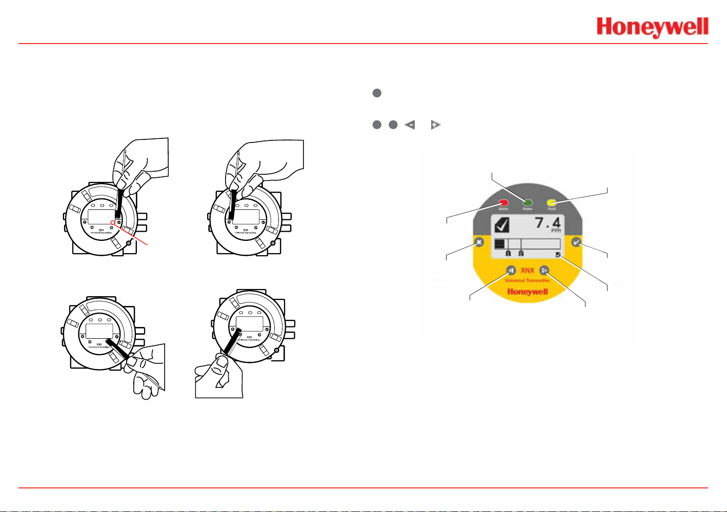
The transmitter uses magnetic switches to enable non-intrusive
operation. To activate a magnetic switch, hold the magnetic end
of the screwdriver up to the glass window and slowly swipe the
magnet directly over the switch area. For best results, hold the
screwdriver as illustrated in Figure 7.
Switch Actuation
Enter/Accept
Visual Indicator
Escape/Back
In some menus where displayed values can be changed, the
magnet must be swiped over the switch to cause the numeral
on the display to advance through the available values. Use the
✖
switch to return to a previous menu or eld.
For the purposes of this manual, the instruction to use
✓, ✖
, or , means to activate the relevant magnetic switch as
described above.
Power LED (green)
Alarm LED (red)
Escape
Move Left
Decement Value
Figure 8. Front panel display of the transmitter
Enter/Accept
Switch Actuation
Visual Indicator
Move Right
Increment Value
Figure 7. Using the magnetic wand
A visual indication of the switch actuation will appear in
the lower right corner of the display each time the switch is
activated.
Introduction
20
Page 23
XNX Universal Transmitter
Current Concentration Level
Alarm 1 Set Point
Current Concentration Le
Warning Code
Warning Icon
Controls and Navigation
Command Description
✓
Enter/Accept
✖
Escape/Back
Move Left/
Decrease Value
Move Right/
Increase Value
The Enter/Accept switch is used to access menus,
accept changes and to answer “yes” to system
prompts.
The Escape/Back switch is used to return to previous
menus or to answer “no” to system prompts.
The Left/Decrement arrow is used to move through
menu options or decrease values when entering text or
numbers.
The Right/Increment arrow is used to move through
menu options or increase values when entering text or
numbers.
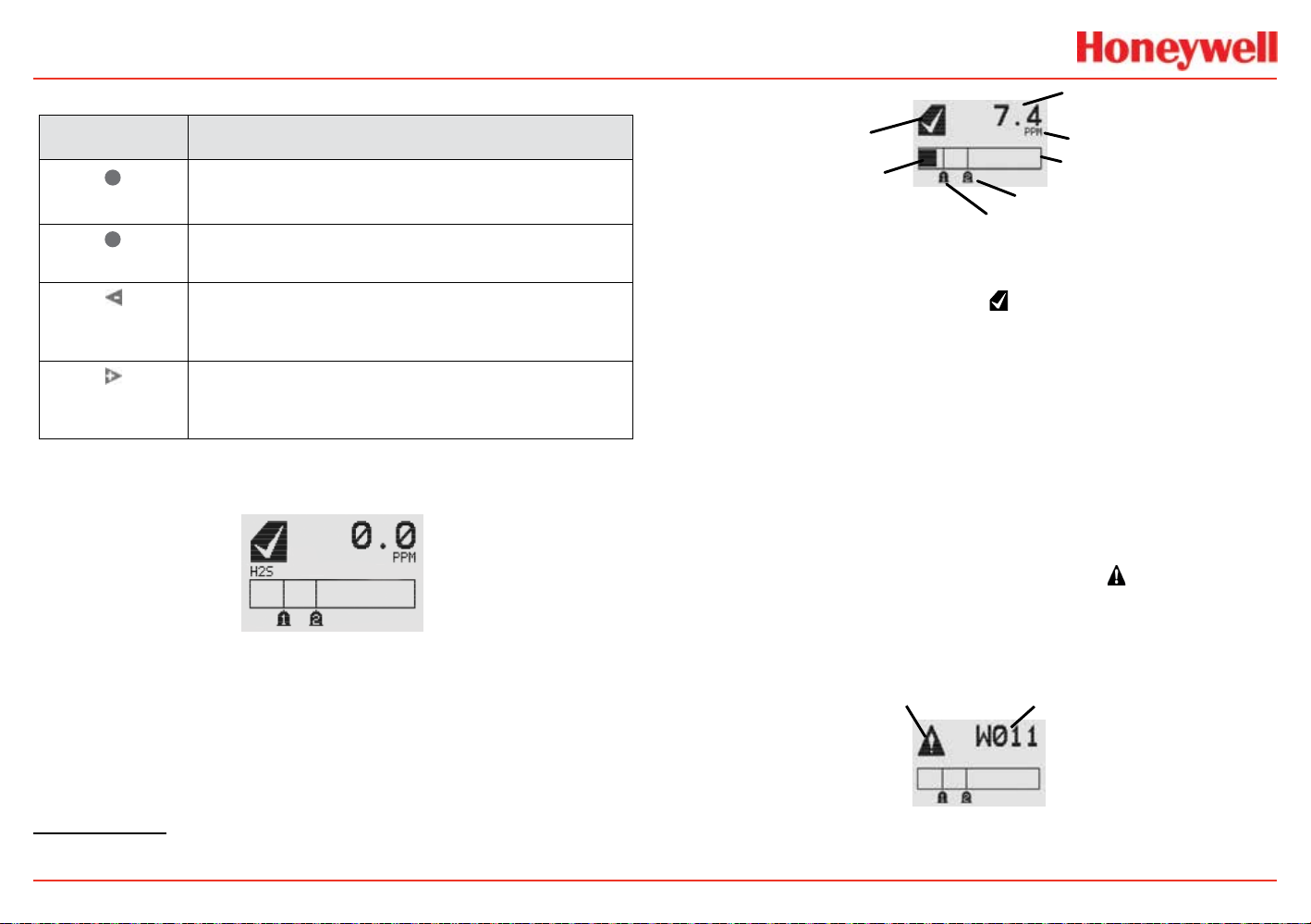
The General Status Screen
\
Figure 9. General Status screen
The General Status screen shows the status of the transmitter.
Warnings, faults, alarm levels, and current concentration levels
are displayed continuously.
3
(Numeric)
Status Indicator
vel
(Bar Graph)
Figure 10. General Status screen, normal operating mode
Concentration Units
Full Scale
Alarm 2 Set Point
The Normal Operating Mode icon indicates proper operation.
The display also shows the concentration level of the target gas
in two ways. In the rst, a numeric value is shown in the upper
right corner of the display in the units selected (ppm, %LEL,
%VOL). The second concentration display is shown in the form
of a bar graph representing the current concentration against
full scale and in relation to the dened alarm levels. For more
information on setting range and alarm levels, see the Range/
Alarm Settings section. See the EC Sensor Performance Data,
Factory Mutual Veried, EC Performance Data, DEKRA EXAM
Veried and the Other EC Sensors sections for negative drift and
zero deviation values.
When a warning is triggered, the warning icon
appears and
information is displayed on the General Status Screen. The
information displayed alternates between screens displaying the
gas concentration and the warning code. See the Warnings and
Faults section for more warning code information.
3
The LCD screen’s refresh rates are 500 milliseconds when the LCD heater is off and 1 second
with the heater on.
Introduction
Figure 11. General Status Warning detail
21
Page 24
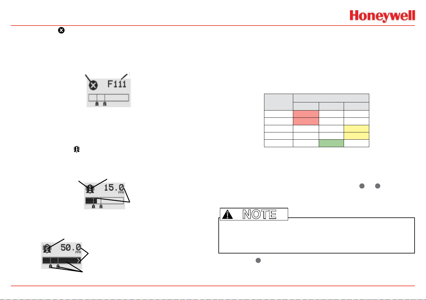
XNX Universal Transmitter
Concentration
Alar
Alarm Level Triggered
Alarm Level Triggered
m Setpoints Flash
NOTE
If the fault icon is displayed, a fault condition has been
triggered and the display will alternate between the target gas
concentration and the fault code. See the Warnings and Faults
section for more fault code information.
Fault Icon
Figure 12. General Status Fault detail
Fault Code
In the event of multiple warnings or faults, the user can view all
messages with the transmitter’s Event History function.
When an Alarm icon
is displayed, the target gas
concentration exceeds one or both preset alarm levels. The
General Status Screen displays the gas concentration and the
alarm level exceeded.
m Icon
Target Gas
Figure 14. General Status Overrange detail
Negative values are not displayed and do not appear on the
4-20 mA output, but they are indicated by faults or warnings
when preset thresholds are exceeded. (See zero deviation in the
Specications section)
In addition to the graphic alarm, fault, and warning indicators,
the LEDs on the front panel ash in these patterns based on the
condition:
Condition
Alarm 1 Solid
Alarm 2 Flashing
Warning Solid
Fault Flashing
Health Flashing
1
The refresh rate of the LEDs is 0.5 second.
2
Special states (Warmup, Inhibit) are not indicated by the Fault LED.
Red Green Yellow
LED1
2
Entering the Menu
Swiping the magnet over the magnetic switch ✓ or ✖ allows the
user to reset faults or alarms, display current settings, or make
adjustments to the device.
Figure 13. General Status Alarm detail
In an overrange condition, the alarm icon will display and the target
gas concentration bar graph and alarm setpoints will ash.
Full Scale
Concentration
Concentration Bar, Alar
Introduction
!
Note: If the Easy Reset option is set to Lock, alarms and faults cannot be reset
without logging in or entering a passcode. For more information, see the Configure
Security section.
Swiping the ✖ or “escape” magnetic switch activates the Alarm
Reset screen and allows alarms to be silenced and faults to be
reset.
22
Page 25
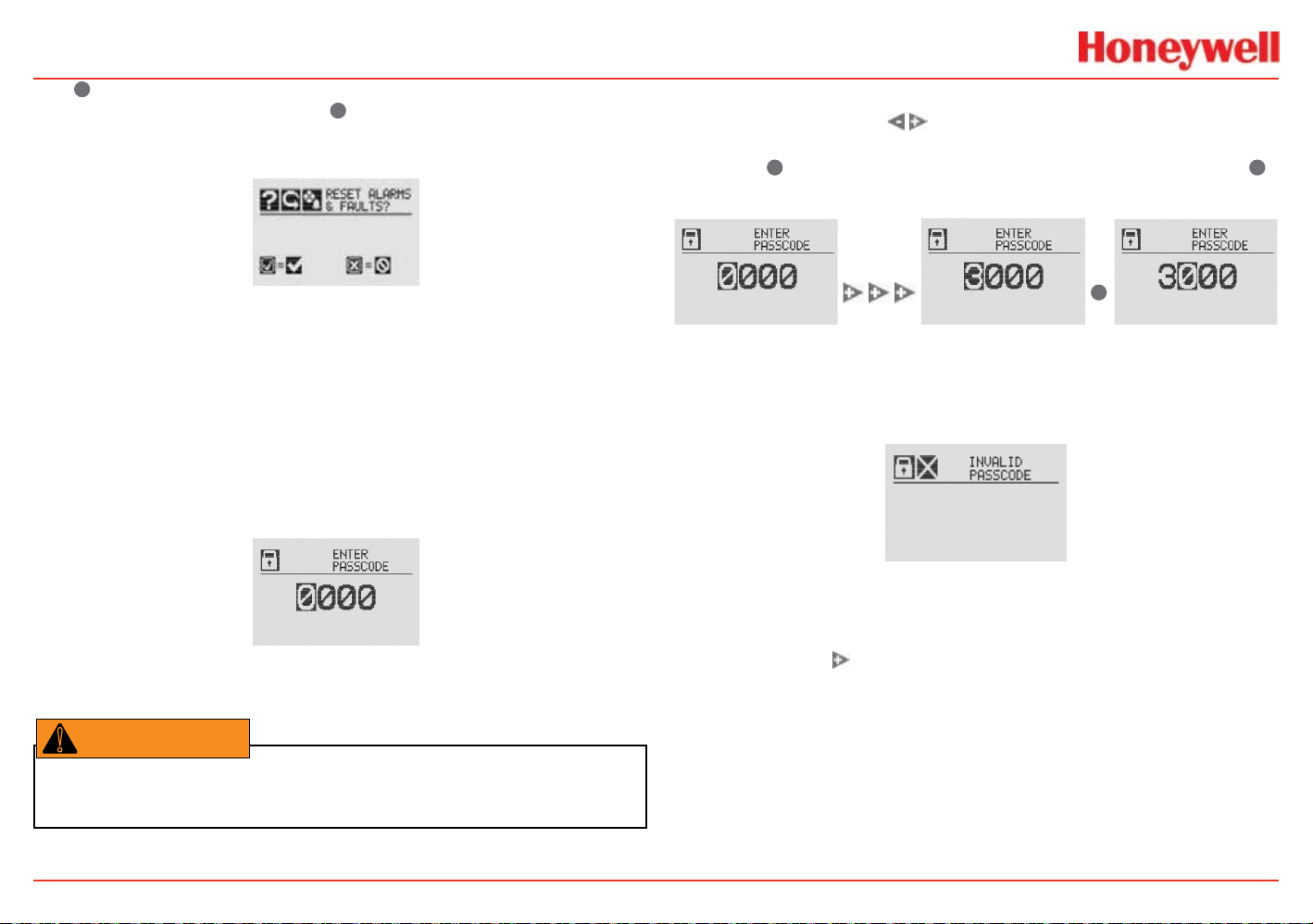
XNX Universal Transmitter
WARNING
!
The ✓ switch resets all alarms and faults and returns to the
General Status screen. Use the
Status screen without resetting the alarms and faults.
Figure 15. Alarm Reset screen
Two authorization levels control access based upon the security
level of the user: Level 1 (routine maintenance) and Level 2
(technician and password administrator). The default passcodes
for both levels are “0000” and must be changed after installation
to control access (see the Configure Security section). In
general, access to neither security level restricts the user to
viewing the transmitter’s display. If desired, the Easy Reset from
Main Status option
access to either security level.
allows alarm and fault resets without requiring
Figure 16. Passcode screen
✖
switch to return to the General
When the Passcode screen is displayed, the rst passcode digit
is highlighted. Use the
through the values. Once the correct value is displayed for the
rst digit,
moves to the previous digit of the passcode.
Repeat for each of the remaining digits in the passcode. If the
passcode is entered incorrectly, the Invalid Passcode screen is
displayed and the user is returned to the General Status screen.
✓
accepts the value and moves to the next digit or ✖
✓
switches to increase or decrease
Figure 17. Entering the passcode
Figure 18. Invalid Passcode screen
Displaying Transmitter Information
While in the General Status display, swipe the magnet over the
magnetic switch
The General Status display will replace the bar graph in the
lower portion of the screen with the unit’s serial number, the
date and time, and the unit’s part number.
to display information about the transmitter.
Warning: The factory-set passcodes must be reset to prevent unauthorized access to
the transmitter’s menus.
Introduction
23
Page 26
XNX Universal Transmitter
?
Figure 19. General Status Screen with unit information
Main Menu
Once the proper passcode has been entered, the transmitter
displays the Main Menu.
Figure 20. The Main Menu
From the Main Menu, a Level 1 user can:
• display the current settings/conguration
• test the transmitter
• calibrate and bump test the transmitter
• congure the unit for language, date and time
The Main Menu consists of these options:
Introduction
24
Menu Description
Configure
Test
Information
Gas
Calibration
Provides access to settings to configure the
transmitter and connected devices
Provides access to tools and settings to allow
simulation of gas events to test the system
Displays current settings for the transmitter
including optional relays and Modbus
Displays the interface to calibrate sensors
attached directly to the transmitter
See
Section...
Configuring
the
Transmitter
Tes t Menu
Information
Menu
Gas
Calibration
Menu
Page 27
XNX Universal Transmitter
Menu Navigation
Introduction
25
Page 28

XNX Universal Transmitter
Information Mode
Alarm/Fault Status
Alarm/Fault
Conrm Alarm/Fault Reset
Reset Alarm/Fault
Date & Time
Transmitter ID, Serial #, Revision
Transmitter Data
Transmitter Status
Transmitter Status
Sensor Type, Serial #, Revision
Sensor Data
Sensor Status
Sensor Status
Gas Name, ID, Range
Gas Data
Range Settings, Alarm Settings
Range/Alarm Settings
mA Level Settings
mA Level Settings
Relay Settings
4
Relay Settings
Fieldbus Settings
5
Fieldbus Settings
Event History
Increment Next/Previous Event
Increment Next/Previous Hour
Increment Next/Previous Day
Increment Next/Previous Alarm
Increment Next Previous Fault
4 Optional relay only
Introduction
5 Optional FOUNDATION Fieldbus and Modbus only
26
Page 29
XNX Universal Transmitter
Test Mode
Inhibit
Enable/Disable Inhibit
Force mA Output
Select Current: 0 to 22 mA
Accept
Force Relay
6
Select Relay 1
Select Relay 2
Select Relay 3
Accept
Alarm/Fault Simulation
Alarm 1 Simulation
Alarm 2 Simulation
Warning Simulation
Fault Simulation
Calibration Mode
Gas Calibration
Enter Span Gas Concentration (Oxygen)
Enter Span Gas Concentration (Not Oxygen)
Bump Test
mA Output Calibration
Adjust 4 mA Output
Adjust 20 mA Output
Soft Reset
Align Excel
7
8
6 Optional relay only
Introduction
7 Searchpoint Optima and Searchline Excel only
8 Searchline Excel only
27
Page 30
XNX Universal Transmitter
Conguration Mode
Select Language
Set Date & Time
Set Date Format
Set Year, Month, Day
Set Hours, Minutes, Seconds
Sensor Type Selection
Set mV Sensor Type
Set mA Sensor Type
Gas Selection
Changing the Gas or Units Name
Gas Selections and Alarm Limits Based on mV
Sensor Type
Range & Alarms
Set Range
Alarm 1 Type
Alarm 1 Setpoint
Alarm 1 Latching or Non-latching
Alarm 2 Type
Alarm 2 Setpoint
Alarm 2 Latching or Non-latching
Selecting the Numeric Format
Latching/Non-latching
Change Meas. Units
mA Output Levels
Change mA for Inhibit
9 Catalytic bead sensor only
10 Searchpoint Optima and Searchline Excel only
11 ECC and mV only
Introduction
9
10
11
Change mA for Warning
Change mA for Overrange
Change mA for Low Signal
Change mA for Blocked Beam
Set Calibration Interval
Accept New Sensor Type
Information screen identifying previous sensor and
new sensor
Screen displays new type and old type
Set Beam Block
13
Select Beam Block Threshold
Select Time to Beam Block
Select Time to Fault
Set Path Length
14
Set New Path Length
Congure Unit ID
Edit ID
Clear ID
Default ID
Relay Options
15
Select A1
Select A2
Fieldbus Options
16
Change Fieldbus Address
Change Fieldbus Speed
Security
Reset and LVL1
LVL1 Code
LVL2 Code
12 Electrochemical and catalytic bead sensors only
13 Searchline Excel only
14 Searchline Excel only
15 Optional relay only
16 Optional FOUNDATION Fieldbus and Modbus only
28
12
Page 31

XNX Universal Transmitter
Installation and Operation
XNX Universal Transmitter Technical Manual
29
Page 32

XNX Universal Transmitter
WARNING
!
CAUTION
!
Sensor Mounting and Location
Warning: Installation must be in accordance with the recognized standards of the
appropriate authority in the country concerned.
Warning: Before carrying out any work, ensure that local regulations and site procedures
are followed. Appropriate standards must be followed to maintain the overall certification
of the sensor.
Caution: Locate transmitters and sensors in accordance with relevant local and national
legislation, standards, and codes of practice.
Caution: Do not locate the transmitter where it will be exposed to direct sunlight.
Caution: Replace a detector only with another of the same type.
Caution: Mount detectors where the gas is most likely to be present.
When determining the placement of sensors, follow the advice of
safety and engineering personnel and experts having specialist
knowledge of gas dispersion, the process plant system, and
the equipment involved. Record the agreement reached on the
location of sensors. Consider these factors when locating gas
sensors:
• possible damage caused by natural events such as rain or
ooding
• ease of access for functional testing and servicing
• how escaping gas may behave due to natural or forced air
currents.
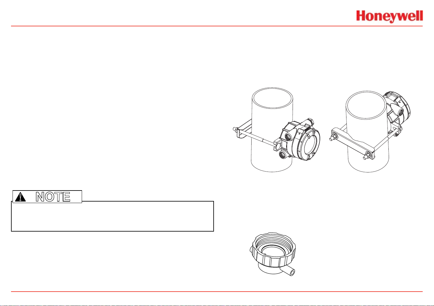
Mounting the Transmitter
The transmitter can be mounted in a number of ways using
the integral mounting tabs. The transmitter can be attached
to at wall surfaces or to Unistrut®. With the optional pipe
mount kit, the unit can be mounted to pipe of diameter 2” to
6” (50 to 150mm). A ceiling mount bracket kit is also available.
7.75"
196.85 mm
6.00"
15.4 mm
5.6"
124.24 mm
0.55"
14.35 mm
1.67"
42.41 mm
Figure 22. XNX Universal Transmitter mounting dimensions and clearances
113.8 mm
1.2"
31.75mm
4.48"
2.054"
52.18mm
0.625"
15.88mm
1.768"
44.90 mm
1.768"
44.90 mm
0.945"
24mm
3.176"
80.67 mm
6.138"
158.75mm
Installation and Operation
30
Page 33

XNX Universal Transmitter
WARNING
!
NOTE
Warning: Any work on the interior of the detector must be conducted only by Honeywelltrained personnel
Warning: To reduce the risk of ignition in hazardous atmospheres, disconnect the
equipment from the supply circuit before opening the sensor enclosure. Keep the
assembly tightly closed during operation. Conduit runs must have a seal fitting connected
within 18 inches (45 cm) of the enclosure.
Warning: Never open the XNX enclosure under power unless the area is known to be
non-hazardous.
Warning: When the transmitter is equipped with the optional Remote Mount Kit, the
remote sensor must be securely mounted in a fixed position. The Remote Sensor kit is not
intended to be used as a handheld sensor.
!
Note: Agency certifications require that EC and mV sensors face down. Optima
sensors must be mounted horizontally.
The transmitter is congured with ve cable/conduit ports built
into the housing for wiring and mounting sensors. Figure 23
provides the guidelines to proper installation of the transmitter.
While relay wiring can use any
available cable/conduit port in
the enclosure, to avoid electrical
noise do not use the same
cable/conduit port for both relay
reset and relay signal lines.
Option Position
Local HART® Option B
XNX Electrochemical Sensor - Local/Remote C
MPD, 705 Series, Sensepoint Series C
Searchpoint Optima Plus A or E
Searchline Excel Typically C
Remote Sensor Connection (except EC) Any remaining
Searchpoint Optima Plus - Remote Any remaining
Modbus Any remaining
Relays Any remaining
Foundation Fieldbus Any remaining
Power Any remaining
Figure 23. Cable/conduit port assignments
Installation and Operation
31
Page 34

XNX Universal Transmitter
Integral Mounting Lugs
Figure 24. XNX Universal Transmitter mounting lugs
Wiring the Transmitter
The transmitter is available in sensor technologies, or personality
options, which support a variety of sensors and applications.
Each of the personalities use a dedicated interface board.
Pluggable terminal blocks are used for easy connection and
service. The personality boards and optional communication
interfaces are enclosed in plastic housings comprising the
electronics POD (Personality, Options, and Display). The
Personality circuit board determines the transmitter’s behavior
based on the type of sensor attached to the interface. See
Specications for drift and zero deviation values.
This table illustrates the three transmitter congurations and the
sensors supported by each.
XNX IR Personality XNX EC Personality
Searchline Excel
Generic mA Sensors XNX EC Sensor Remote Mount Kit
Searchpoint Optima Plus Local/
Remote
XNX EC Sensor
Figure 25. Optional pipe and ceiling mounts
Installation and Operation
XNX mV Personality
705 Local / Remote MPD Local (cat bead and IR) Sensepoint Local / Remote
705HT Local / Remote MPD Remote Sensepoint PPM Local/Remote
Sensepoint HT Remote
Figure 26. XNX Transmitter personalities
32
Page 35

XNX Universal Transmitter
CAUTION
!
WARNING
!
Caution: Before wiring the transmitter, confirm that the correct personality and
communication boards are installed.
performance of the transmitter. For best reliability use resistive
loads only.
Isolation
Isolate the power and signal-carrying conductors.
General Wiring Considerations
For proper operation of the transmitter and sensor technologies,
consideration of wiring-induced voltage drops, transient
electrical noise, and dissimilar earth ground potentials is
imperative in the design and installation of the system.
Warning: The sensor must be earthed/grounded for intrinsic safety, electrical safety
and to limit the effects of radio frequency interference. Earth/ground points are provided
inside and outside the unit. EMI note for applications using shielded cable: Cable shield
must provide 90% coverage of the wiring. Cable shield terminations must be made at the
cable glands with suitable EMI type glands. Avoid terminating cable shields at the Earth
ground lug inside the XNX enclosure. In cases where wiring is in pipe, a shielded cable is
not required. The external terminal is only a supplemental bonding connection where local
authorities permit or require such a connection.
Loading
When wiring for DC power, 4-20mA signal, remote wiring to
sensors must be sized sufciently to provide adequate voltages
for the line length and the loads that will be used.
Circuit Protection
Supply circuits must provide over-current protection. Consider
inrush current in specifying any DC supply. Power supply range
is 16 to 32 VDC for EC and mV versions, 18 to 32 VDC for
Searchpoint Optima Plus and Searchline Excel, and 16 to 32
VDC depending on the limitations of the device for the generic
4-20mA input.
Distance Considerations for Installation
Adequately powering the transmitter is the factor that
determines an installation’s maximum distance. The 4-20 mA
output signal will easily handle the distance back to the control
equipment.
The primary factors determining distance are the minimum oper-
ating voltage of the transmitter and/or sensor; the maximum
current draw of the transmitter/sensor, the resistance of the
wire used, the power supply voltage, and the current capacity
of power supply. An additional consideration is the type of
installation; specically, how many transmitters/sensors are
drawing power from the same power supply and whether these
transmitters are using the same pair of wires (“daisy-chained”) or
have their own connections.
The use of high inrush or inductive loads may affect the
Installation and Operation
33
Page 36

XNX Universal Transmitter
Power Supply Power Supply Power Supply
Power Supply
Types of Installations
There are three basic types of installation: a single transmitter;
multiple transmitters connected to a single power source; and
multiple transmitters connected in a “daisy-chain” conguration.
Single Transmitter
This is the simplest type of installation. It consists of a single
XNX transmitter installation per power source.
Figure 27. Single transmitter installation
Advantages:
Advantages:
• Maximum distance between power source and transmitters
• Fewer power sources.
Disadvantages:
• Larger power source will be needed
• If a power source fails, several monitoring points fail.
Multiple Transmitters Connected in a “Daisy-Chain”
Configuration
This conguration consists of two or more transmitters installed
in a line. The power connections are installed as an extension of
the previous transmitter, with the rst transmitter being the only
one actually wired to the power source.
• Maximum distance between power source and transmitter
• Smaller power source
• If a power source fails, only one monitoring point fails.
Disadvantage:
• Multiple transmitters require multiple power sources.
Multiple Transmitters Connected to a Single Power Source
This is two or more transmitters sharing a single power source
with each transmitter having its own dedicated wiring to the
power source.
Figure 28. Multiple transmitters powered by a single power supply
Installation and Operation
Power Supply
Figure 29. Daisy-chained transmitters from one power supply
Advantages:
• Less wire needed for installation
• Fewer power sources.
Disadvantages:
• Requires a larger power source
• Shorter distance between power source and transmitters.
• If a power source fails, several monitoring points fail.
34
Page 37

XNX Universal Transmitter
NOTE
!
Note: CSA/FM certification does not cover daisy-chained XNX combustible gas transmitters.
Power Source Selection
For each type of installation, selection of power supply is
important. Power supplies are rated by voltage and power. The
nominal voltage for all XNX transmitters is 24V with the power
required depending on the number of points using the same
power supply.
As a general guideline, the power supply should be capable
of providing more power than is required by the installation. A
10 watt power supply is ne for a single XNX mV with catalytic
sensor (6.5 watts required, see the following table) but is
inadequate for a single XNX IR with Searchpoint Optima Plus (10
watts required).
XNX Universal Transmitter Maximum Power Consumption
-40°C to +65°C -10°C to +65°C
HART over 4-20mA
with Relay, Mod-
bus, or Foundation
Fieldbus
(watts)
Configuration
transmitter with toxic
sensors
transmitter with
catalytic sensors
transmitter with
infrared cartridge
HART
over
4-20mA
(watts)
HART over 4-20mA
with Relay, Modbus
FoundationTM Fieldbus
(watts)
®
, or
HART
over
4-20mA
(watts)
5.1 6.2 3.4 4.5
5.4 6.5 3.7 4.8
5.4 6.5 3.7 4.8
XNX Universal Transmitter Maximum Power Consumption
-40°C to +65°C -10°C to +65°C
HART over 4-20mA
with Relay, Mod-
bus, or Foundation
Fieldbus
(watts)
Configuration
transmitter with
Searchpoint Optima
Plus
transmitter with
Searchline Excel
HART
over
4-20mA
(watts)
HART over 4-20mA
with Relay, Modbus
FoundationTM Fieldbus
(watts)
®
, or
HART
over
4-20mA
(watts)
8.6 9.7 6.9 8.0
12.1 13.2 10.4 11.5
To determine the wattage required, add the maximum power
requirements of all the points that will share the power supply.
For example, consider a system with two XNX mV transmitters
with catalytic sensors (6.5 watts each) and one XNX IR with
Searchpoint Optima Plus (10 watts). A 25 watt power supply
would probably handle this installation, but a 30 watt power
supply would be a better choice.
Wire Selection
The type of wire used for connections has an effect on the
distance of the installation. This is because some of the voltage
is dropped across the cable between the power supply and the
transmitter.
Thinner wire (i.e., 18 AWG) will lose more voltage than thicker
wire (i.e., 12 AWG). The amount of voltage lost depends on how
much current is being drawn through the wire; more current
means more loss. If too much voltage is ropped across in the
wiring, there may not be enough at the distant point to allow the
transmitter to operate.
Installation and Operation
35
Page 38

XNX Universal Transmitter
Single Transmitter Distances
For installations that have dedicated wiring between the
transmitter and the power supply, use the following chart. These
distances assume stranded wire is used. If multiple transmitters
are using the same power supply, make sure the power
supply wattage rating is high enough to power all transmitters
simultaneously.
OR
Power Supply
Configuration
transmitter mV or EC
with sensor
transmitter IR with
Searchpoint Optima Plus
transmitter IR with
Searchline Excel
Figure 30. Single transmitter distances
Single Transmitter Distances
18 AWG
[1.0 mm2]
1140 feet
[347 meters]
[551 meters]
660 feet
[201 meters]
[323 meters]
550 feet
[168 meters]
[270 meters]
Power Supply
16 AWG
[1.5 mm2]
1810 feet
1060 feet
890 feet
14 AWG
[2.0 mm2]
2890 feet
[880 meters]
1690 feet
[515 meters]
1410 feet
[430 meters]
12 AWG
[3.5 mm2]
4620 feet
[1408
meters]
2690 feet
[820 meters]
2260 feet
[690 meters]
Daisy-Chained Transmitter Distances
It is difcult to calculate distances for this conguration. There
are many factors to be considered: distance from control room
to rst transmitter, distance between transmitters, sensor types,
etc. A few scenarios are presented here to provide a base to
work from.
Transmitter 1 Transmitter 2 Transmitter 3 Transmitter 4 Transmitter 5
Power Supply
“d”“d”“d”
Figure 31. Daisy-chained transmitter distances
“d”
1. Several transmitters equally spaced from themselves and
the power source.
2 Transmitters - Distance “d”
Configuration
transmitter mV or EC
with sensor
transmitter IR with
Searchpoint Optima Plus
transmitter IR with
Searchline Excel
18 AWG
[1.0 mm2]
380 feet
[115 meters]
220 feet
[67 meters]
185 feet
[56 meters]
16 AWG
[1.5 mm2]
600 feet
[183 meters]
350 feet
[106 meters]
295 feet
[90 meters]
14 AWG
[2.0 mm2]
960 feet
[292 meters]
560 feet
[170 meters]
470 feet
[143 meters]
“d”
12 AWG
[3.5 mm2]
1540 feet
[469 meters]
900 feet
[274 meters]
750 feet
[229 meters]
Installation and Operation
36
Page 39

XNX Universal Transmitter
Configuration
XNX mV or EC
With Sensor
XNX IR with
Searchpoint Optima Plus
XNX IR with
Searchline Excel
Configuration
XNX mV or EC
With Sensor
XNX IR with
Searchpoint Optima Plus
XNX IR with
Searchline Excel
Configuration
XNX mV or EC
With Sensor
XNX IR with
Searchpoint Optima Plus
XNX IR with
Searchline Excel
3 Transmitters - Distance “d”
18 AWG
[1.0 mm2]
190 feet
[58 meters]
110 feet
[33 meters]
90 feet
[27 meters]
16 AWG
[1.5 mm2]
300 feet
[91 meters]
175 feet
[53 meters]
145 feet
[44 meters]
4 Transmitters - Distance “d”
18 AWG
[1.0 mm2]
110 feet
[33 meters]
65 feet
[20 meters]
55 feet
[17 meters]
16 AWG
[1.5 mm2]
180 feet
[55 meters]
105 feet
[32 meters]
85 feet
[26 meters]
5 Transmitters - Distance “d”
18 AWG
[1.0 mm2]
75 feet
[23 meters]
45 feet
[13 meters]
35 feet
[11 meters]
16 AWG
[1.5 mm2]
120 feet
[36 meters]
70 feet
[21 meters]
55 feet
[17 meters]
14 AWG
[2.0 mm2]
480 feet
[146 meters]
280 feet
[85 meters]
235 feet
[71 meters]
14 AWG
[2.0 mm2]
290 feet
[88 meters]
165 feet
[50 meters]
140 feet
[43 meters]
14 AWG
[2.0 mm2]
190 feet
[58 meters]
110 feet
[33 meters]
90 feet
[27 meters]
12 AWG
[3.5 mm2]
770 feet
[234 meters]
450 feet
[137 meters]
375 feet
[114 meters]
12 AWG
[3.5 mm2]
460 feet
[140 meters]
270 feet
[82 meters]
225 feet
[68 meters]
12 AWG
[3.5 mm2]
300 feet
[91 meters]
180 feet
[55 meters]
150 feet
[46 meters]
2. Several transmitters installed in pairs with each pair
equally spaced from the next pair and the power source.
These distances assume the paired transmitters are
installed within 10 feet [3 meters] of each other.
Transmitters 1 and 2 Transmitters 3 and 4 Transmitters 5 and 6
Power Supply
“d”“d”“d”
Figure 32. Transmitters in pairs
2 Transmitters - Distance “d”
Configuration
XNX mV or EC
With Sensor
XNX IR with
Searchpoint Optima Plus
XNX IR with
Searchline Excel
Configuration
XNX mV or EC
With Sensor
XNX IR with
Searchpoint Optima Plus
XNX IR with
Searchline Excel
18 AWG
[1.0 mm2]
485 feet
[147 meters]
380 feet
[115 meters]
280 feet
[85 meters]
4 Transmitters - Distance “d”
18 AWG
[1.0 mm2]
190 feet
[58 meters]
110 feet
[33 meters]
90 feet
[27 meters]
16 AWG
[1.5 mm2]
775 feet
[235 meters]
600 feet
[180 meters]
440 feet
[134 meters]
16 AWG
[1.5 mm2]
300 feet
[91 meters]
175 feet
[53 meters]
145 feet
[44 meters]
14 AWG
[2.0 mm2]
1230 feet
[292 meters]
960 feet
[290 meters]
700 feet
[213 meters]
14 AWG
[2.0 mm2]
480 feet
[146 meters]
280 feet
[85 meters]
235 feet
[71 meters]
12 AWG
[3.5 mm2]
1970 feet
[600 meters]
1540 feet
[470 meters]
1130 feet
[344 meters]
12 AWG
[3.5 mm2]
770 feet
[234 meters]
450 feet
[137 meters]
375 feet
[114 meters]
Installation and Operation
37
Page 40

XNX Universal Transmitter
J1 - Remote HART Connector Only
Personality
Boards
Option
Boards
A
B
C
D
E
F
6 Transmitters - Distance “d”
Configuration
XNX mV or EC
With Sensor
XNX IR with
Searchpoint Optima Plus
XNX IR with
Searchline Excel
18 AWG
[1.0 mm2]
95 feet
[33 meters]
55 feet
[17 meters]
45 feet
[14 meters]
16 AWG
[1.5 mm2]
150 feet
[45 meters]
85 feet
[26 meters]
70 feet
[21 meters]
14 AWG
[2.0 mm2]
240 feet
[73 meters]
140 feet
[42 meters]
115 feet
[35 meters]
12 AWG
[3.5 mm2]
385 feet
[117 meters]
225 feet
[68 meters]
185 feet
[56 meters]
Ensure that wiring is adequately protected from mechanical
damage during installation. Shorted or open-circuit wiring to an
MPD **I** sensor may result in a full-scale concentration reading
before the transmitter’s internal diagnostics can identify the
external installation fault.
POD Connections
This illustration shows the connections available on of the
terminal blocks for each type of personality board.
Figure 33. Personality board terminal block legend
Each of the personalities uses a single terminal block for
connection with the exception of the IR personality, which
features a second terminal block.
The personality boards also provide a dedicated pair of jumper
switches to dene output of the transmitter as isolated 4-20mA,
Sink 20mA, or Source 20mA as well as a service jumper to allow
power to the loop to continue when the transmitter is being
serviced. A separate connector is used to activate local HART
(see the Local HART Interface section).
Installation and Operation
Local HART provides an external access to control the
transmitter. An intrinsically safe (IS) barrier inside the
transmitter allows the user to attach an external handheld eld
communicator for programming and conguration. The external
interface is intrinsically safe. It is installed in the transmitter’s
lower left cable/conduit port.
38
Page 41

XNX Universal Transmitter
NOTE
WARNING
!
Table A Table B
Board Type Function S1 S2 Board Type Connection Function
EC Personality
mV
Personality
IR
Personality
Board Type Function S3 S4 Board Type Connection Function
IR
Personality
Board Type Connection Function Board Type Connection Function
Relay TB4
Modbus SW5
Foundatin
Fieldbus
4-20mA
Output
Table C Table D
IR 4-20mA
Input
Table E Table F
SW5 Simulation Mode
Source
Sink
Isolated
Remote Reset
Connector
Bus Loop
Terminators
Source
Sink
EC Personality
mV Personality
TB1
IR Personality
EC Personality J2 EC IS Barrier
IR Personality TB2 Com A and B
Relay TB3 Relay Output
Modbus TB3 Data Connection
Foundation
Fieldbus
TB3 Data connection
Power, 4-20mA
Power, 4-20mA,
Sensor
Power, 4-20mA,
IR Power and
Signal
!
Note: Open loop faults are not available due to HART, Modbus, and FOUNDATION Fieldbus
interfaces where a 4-20 signal cannot be used. In this case, open loop, 0mA must be
used as the diagnostic.
The Option circuit boards vary depending upon the option
selected when ordered. Only one of the three available interface
options (relays, Modbus, or FOUNDATION Fieldbus) can be
attached to the transmitter. When installed, connections to the
options are made to connectors at the bottom of the POD
Installation and Operation
.
4-20mA Output, Common Connections, and Power
Settings
Warning: Power off the transmitter before changing S3 or S4. Failure to do this will
permanently damage the transmitter. Both switches must be set in either Source or
Sink prior to applying power.
The transmitter allows the user to congure the 4-20mA
output to Sink, Source, or Isolated mode operation via two
programming switches on the POD
table shows the S1 and S2 setting and corresponding output
conguration.
Switch Configuration
Mode S1 S2
Source Down Up
Sink Up Down
Isolated Down Down
Most controllers in the market will accept source-congured
devices. Sink-congured signals are used in older technology
controllers, which reduce the need for complete system
upgrades. In isolated-signal devices, if the controller fails or the
mA signal wires are disconnected or broken, the eld device will
remain operational. Most controllers in the market will accept
isolated congured devices.
Power and 4-20mA connections are made at TB-1 and are
identical for the EC, IR, and mV Personality Boards. For user
convenience, a second set of +Ve and -Ve power terminals have
been provided to eliminate the need for a secondary junction
1 The 4-20 mA output state is refreshed at least every two seconds (once per second is typical).
39
1
. The Switch Conguration
Page 42

XNX Universal Transmitter
Controller
+VE
Signal
-VE
R
L
1
2
3
1-1
1-5
1-3
+V
+mA
-V
XNX
XNX Sink Configuration
Current
Flow
XNX Source Configuration
Controller
+VE
Signal
-VE
R
L
1
2
3
1-1
1-6
1-3
+V
-mA
-V
XNX
Current
Flow
Terminate cable screen at the detector or controller, not both�
Controller
+V1
+V2
-V2
1-1
1-5
1-6
+V
+mA
-V
XNX
1-3
-mA
-V1
XNX Isolated Configuration
NOTE
box in multi-node systems when used with the supplied terminal
jumpers. These jumpers enable an electrical connection without
connecting to the Personality Board. Install them between pins 1
and 2 and between pins 3 and 4 to support multi-node wiring.
Keep the total load resistance for the 4-20mA between 200 and
500Ω, including the resistance of the properly selected 4-20mA
cable and input impedance of the equipment to be connected.
Failure to perform ‘Calibrate mA Output’ or with loads outside
the recommended values may result in a diagnostic warning or
fault messages.
If the 20 mA output is not used, a 500 ohm resistor must be
installed.
The transmitter’s power consumption is dependent on the
sensor and options for the specic conguration. For proper
operation, the input voltage must be maintained between 16 and
32 VDC for EC and mV units and between 18 to 32 VDC for IR
units.
Figure 35. Source wiring
Figure 36. Isolated wiring
Labels applied to the back of the POD identify each of the
connection points.
Installation and Operation
!
Figure 34. Sink wiring
Note: Pins 2 and 4 of terminal block TB1 have no internal connection on the
personality board. When used with the terminal block jumpers, pins 2 and 4 can
provide additional 4-20mA connections or supply power for daisy-chained units.
40
Page 43

XNX Universal Transmitter
WARNING
!
NOTE
!
Note: FOUNDATION Fieldbus XNX transmitters require a separate power source and
cannot be powered via the bus.
Terminal Block Connections
Connections to the transmitter are made via pluggable terminal
blocks secured to the back of the POD. The terminal blocks are
keyed and polarized. A color coded label assists in wiring when
the block is removed from the POD.
FOUNDATION Fieldbus Wiring
FOUNDATION Fieldbus connections to the transmitter are
made through a pluggable terminal block on the FOUNDATION
Fieldbus option board, shown in Figure 38. A simulation switch
(SW5) is included on the board to enable/disable simulation
mode. Terminals 3-1 through 3-4 are provided to facilitate bus
wiring; there is no internal connection to other XNX circuitry.
Terminal 3-1 is connected internally to 3-2. Similarly, terminal 3-3
is connected internally to 3-4.
FOUNDATION Fieldbus
4
5
6
Internal ground lug
ground cable
to internal
ground lug
S5 Sim Mode
Out
In
TB-3 Modbus
+
+
TB-3 FFB
3-1
F+
F+
3-2
3-3
F-
3-4
F-
3-5
FS
FS
3-6
Use shorting jumper
supplied to maintain
connection during
service
1
2
SW5 -
Sim switch
Jumper
assignments
3
The terminals are suitable for use with 12 to 28 AWG or 0.8
2
to 2.5 mm
wire. Wire insulation must be stripped 5/16” (8 mm).
Tighten each terminal to a maximum of 4.5 in-lbs (0.51 Nm). Up
to four terminal blocks are provided; each having 2, 6, 9, or 10
positions.
Two terminal block jumpers are included to provide an electrical
connection without connection to the Personality Board. Install
the jumpers between pins 1 and 2 and between pins 3 and 4 to
support multi-node wiring.
Warning: When the transmitter is equipped with the optional Remote Mount Kit, the
remote sensor must be securely mounted in a fixed position. The Remote Sensor kit is
not intended to be used as a handheld sensor.
Figure 37. FOUNDATION Fieldbus option board and terminal block
Installation and Operation
41
Page 44

XNX Universal Transmitter
CAUTION
EC Personality Wiring
Terminal Block Jumper
IN
TB-1 T erminal Block
OUT
XNX EC TB-1
Figure 38. Pluggable terminal block and terminal block jumper
!
Caution: Do not force the POD into the enclosure. Doing so may result in damage to
the wiring or the POD or may alter the switch settings. If resistance is felt, wires may
be preventing the POD from being properly positioned.
J1 - Local HART Connector
S1 and S2 - Signal Output
Jumper Switch
Source
Sink
Isolated
▼
▲
J2 - EC Barrier Connector
XNX EC TB-1
1
2
3
4
5
6
S2S1
▲
▼
▼▼
TB1
Position EC
1 +24
2
3 0v
4
LOCAL
20 mA
Operation
S1
S2
16-32 VDC
6.2W max.
4-20mA
HART
EC TB-1
EC Barrier
J1
HART
Source
Sink
Isolated
+V 1-1
-V 1-3
+mA 1-5
-mA 1-6
S1
S2
1-2
1-4
J2
Installation and Operation
Figure 39. XNX EC personality board terminal blocks and jumper switches and terminal
block assignments
42
Page 45

XNX Universal Transmitter
Optional Local HART
Remote Sensor Kit
CAUTION
Sensor Mounted to
IS Barrier must
be connected to J1
S1 S2
J1 HART
1
2
3
4
Terminal Block 1
5
-+6
HART
Adaptor
Sensor Cartridge
Sensor Retainer
Weatherproof Cap
Local HART
IS Barrier
(optional)
J2 EC Barrier
EC IS Barrier must
be connected to J2
EC IS Barrier
EC
Adaptor
Local Sensor Mounted to Transmitter
For FM compliance, the tag supplied with
XNXXSH1FM and XNXSO1FM cartridges must be
attached to the transmitter or remote mount kit.
Figure 40. EC personality wiring
Sensor Cartridge
Sensor Retainer
Weatherproof Cap
Electrochemical Sensor Installation
!
Caution: A missing oxygen cell will result in 0% V/V O2 gas concentration, thus
triggering alarm events. In this situation, check the connection of the EC cell to the
sensor connector board.
Caution: For biased sensors (e.g., nitrogen dioxide) remove the sensor stabilizer from
the bottom of the sensor prior to installation.
Using the Installing plug-in sensor illustration as a guide, follow this
procedure:
1. Verify that the label on the new sensor is the correct gas
type.
2. Unscrew the weatherproof cover, loosen the retainer
locking screw with the supplied hex key, and unscrew the
sensor retainer.
3. Plug in the new sensor. Take care to align the sensor pins
with the connector.
4. Ret the sensor retainer, tighten the locking screw with the
hex key, and ret the weatherproof cover. Countdown time
of up to 180 seconds (depending on the sensor type) will
be displayed.
5. Acknowledge the gas type (required before proceeding).
For more information on setting gas type, see the Gas
Selection section.
6. After the sensor is installed and the gas type is conrmed,
the range, alarm levels, and other important settings must
be set; see the Conguring the Transmitter section.
7. After the transmitter has been congured, calibrate the
sensor following the procedures in the Calibration section.
Installation and Operation
43
Page 46

XNX Universal Transmitter
Weatherproof Cap
NOTE
CAUTION
!
WARNING
!
Transmitter
New Sensor
Sensor Retainer &
Locking Screw
EC Sensor Remote Mounting Kit
The remote sensor mounting kit is used to mount the EC sensor
away from the transmitter. To mount the sensor remotely, follow
this procedure:
1. Unscrew the weatherproof cover, loosen the retainer
locking screw and unscrew the sensor retainer.
2. Remove the sensor by pulling (without twisting).
3. Plug the remote sensor cable connector into the bottom of
the transmitter and secure the retainer.
4. Route the cable to the location where the remote sensor is
to be mounted.
5. Optional: make a loop of cable at the junction box. This
will provide some excess for future re-terminations.
6. If necessary, cut the cable to the required length.
3
2
1
Figure 41. Installing plug-in sensor
4
5
!
Note: Refer to control drawings 3000E3157 and 3000E3159 for the installation
requirements and the remote mounting of EC cells.
Installation and Operation
Caution: Do not cut the cable too short. Once cut, additional lengths of cable cannot
be added as this will invalidate the intrinsically safe certification.
Warning: Enclosures of remotely mounted sensors contain aluminum. Be careful to
avoid ignition hazards due to impact or friction when installed in Zone 1 locations.
7. Mount the remote sensor junction box, allowing enough
room below to t the sensor and weatherproof cover. See
control drawing 3000E3159 in the Remote Sensor Mount
section for specic mounting information.
44
Page 47

XNX Universal Transmitter
8. Attach the cable to the remote terminal box via the gland
provided.
9. Make the connections as shown in the Installing a remote
sensor mounting kit illustration on the next page.
10. Fit the Terminal box lid.
11. Plug the sensor into the socket at the bottom of the terminal
box.
12. Fit the sensor retainer, tighten the locking screw, and t
the weatherproof cover.
13. Calibrate the sensor following the procedure in
and Span Calibration for EC Sensors, mV Sensors, and
Searchpoint Optima
section
.
the
Zero
Connections
Pin # Color
1 Yellow
2 Green
3 Blue
4 White
5 Red
Black
6
Sensor Cartridge
Sensor Retainer
Installation and Operation
Weatherproof Cap
Sensor Mounted to Remote Sensor Kit
Figure 42. Installing a remote sensor mounting kit
45
Page 48

XNX Universal Transmitter
CAUTION
!
NOTE
!
CAUTION
HART
20 mA
Operation
LOCAL
J1
S1
+V 1-1
mV TB-1
MPD, 705
Sensepoint
4-20mA
HART
16-32 VDC
6.5W max.
1-2
-V 1-3
1-4
+mA 1-5
-mA 1-6
Sense
1-7
0v 1-8
Ref 1-9
S1
Source
Sink
Isolated
S2
S2
J1 - Local HART Option Connector
1
2
3
4
5
6
7
8
9
internal
grounding lugs
S1 and S2 - 20mA Output
Jumper Switch
S2
S1
▼
▼
Isolated
▲
Sink
▼
Source
▼
▲
XNX mV TB-1
mV Personality Wiring
A transmitter with the mV personality board allows interface to
the Multi Purpose Detector (MPD), 705, and Sensepoint devices.
Caution: See Specifications to ensure that the transmitter and the mV sensor have the
appropriate approvals prior to commissioning.
Caution: Verify that the mV sensor being installed has compatible threads (3/4 NPT or
M25).
Read the Wiring the Transmitter section which denes the
power and 4-20mA output connections that are common to all
personalities.
Connections from the mV sensor to the transmitter are made
via a single pluggable terminal block. Honeywell Analytics
recommends that an 8” (20 cm) service length for wiring be
maintained. The wire colors for the connections for each sensor
type are shown in the table on this page.
Verify that wires for 4-20mA outputs are routed away from
sources of noise such as relay wires.
Note: The black and red wires from the MPD are not used with the mV personality
board. Ensure that they are properly isolated from live connections. Do not cut the
wires.
!
Caution: Dress the wires properly so that cabling does not contact switches 1 or 2
on the back of the POD. Do not force the POD into the enclosure. Doing so may result
in damage to the wiring or the POD. If resistance is felt, wires may be preventing the
POD from being properly positioned.
Installation and Operation
Figure 43. mV personality board terminal blocks and jumper switches
Wire Color from Sensor
mV Catalytic Bead Sensor
TB-1 Desc.
MPD
Pins 1-6
7 Sense Brown Red Brown
8 0v White Green White
9 Ref Blue Blue Blue
*Internal earth ground; approximately one inch of the black sheath that contains the Sensepoint PPM’s four wires (red, blue,
green, silver) must be split to allow the silver grounding wire to reach the internal grounding lugs.
See subsections in the 4-20 mA Output, Common Connections, and Power Settings section for pin
705
705HT
Sensept
Senspt HT
Sensept
PPM*
identification
mv MPD w/IR Sensor
IR 5%
CO
2
CH
4
46
IR Flam
Page 49

XNX Universal Transmitter
S1 S2
J1 HART
1
2
3
4
5
Terminal Block 1
6
-
7
Sense
8
Com
Ref+9
Internal Ground Lug
Local HART
IS Barrier
(optional)
Optional Local HART
IS Barrier must
be connected to J1
Sense 7
Com 8
Ref 9
mV Remote Sensor Mounting
The sensor can be mounted remotely from the transmitter; the
installation will vary by installed location, sensor and thread type
used. To remotely mount the sensor, follow this procedure:
1. Install a junction box appropriately rated for the
environment. Allow sufcient room for the installation and
calibration of the sensor. (MPD sensors must be installed
with the sinter pointing down.)
2. Loosen the retainer locking screw on the transmitter with
the supplied hex key.
3. Unscrew the transmitter’s weatherproof cover and loosen
the retainer locking screw with the supplied hex key.
4. Run conduit or cable from one of the transmitter’s
available conduit ports to the location of the remote
terminal housing in accordance with local requirements.
A terminal housing provides a mounting base for the
sensor. The installation wiring enters the terminal housing
via conduit. UL and CSA require a conduit pour tting
within 18 in. (45 cm) of each enclosure.
HART
Adaptor
Figure 44. mV personality wiring
Installation and Operation
MPD
705
Sensepoint
Ground Wire from
Sensepoint PPM and HT
UL/CSA Aluminum Junction Box
2441-0022
ATEX/IEC Junction Box
00780-A-0100
Figure 45. Remote terminal housings
The distance between transmitter and remote installation must
comply with these parameters to ensure proper operation.
Distances are dependent on sensor types and the wire gauge
used.
47
Page 50

XNX Universal Transmitter
WARNING
!
AWG Metric Wire Gauge
24 0.25 mm
MPD CB1, 705 Series.
Sensepoint Series
2
Sensors
MPD IC1, IV1 & IF1 Sensors
12m (47 ft.) 30m (97 ft.)
22 20m (65 ft.) 50m (162 ft.)
20 0.5 mm
2
30m (97 ft.) 80m (260 ft.)
18 50m (162 ft.) 120m (390 ft.)*
16 1.0 mm
* Fluctuations in temperature have a greater impact on smaller wire diameters and therefore may require
more frequent zero calibrations.
2
80m (260 ft.)* 200m (650 ft.)*
5. Wire the pluggable terminal block as shown in the mV
personality board illustration then plug the connector into
the back of the mV personality board. In remote mount
MPD congurations, the 3 wires connecting the pluggable
terminal block and the remote MPD must be routed
through the supplied ferrite bead (Honeywell Analytics
part no. 0060-1051, supplied in the accessory kit) as
shown in Figure 46.
Internal Ground Lug
(do not use)
Power
Ferrite Bead
for Remote
Sensor Wiring
XNX Universal Transmitter
mV
Remote
Sensor
Figure 46. Ferrite bead wiring
6. Mount the remote sensor junction box with sufcient room
below to t the sensor and weatherproof cover.
Installation and Operation
Warning: Install the junction box according to local codes and manufacturer’s
requirements.
7. Attach the conduit to the remote terminal box. The
junction box provides a mounting base for the sensor and
contains the associated electronic circuit.
8. In the remote junction box, connect the wires from the
transmitter to the 3-way terminal block in the terminal box.
48
Page 51

XNX Universal Transmitter
NOTE
!
WARNING
!
NOTE
!
CAUTION
!
Note: The black and red wires from the MPD are not used with the mV personality
board. Ensure that they are properly isolated from live connections. Do NOT cut the
wires.
Warning: The enclosures of remotely mounted 705HT sensors contain aluminum. Be
careful to avoid ignition hazards due to impact or friction when installed in Zone 1
locations.
All cable port devices and blanking elements must be certied in
type of explosion protection ameproof enclosure “Ex d” or “Ex e”,
suitable for the conditions of use and correctly installed.
9. Plug the connector into the back of the mV personality board.
10. Install the mV sensor.
11. Terminate wiring at the mV sensor.
12. At the transmitter, pass the wires through the ferrite bead as
shown in Figure 46 and terminate the wiring at the pluggable
terminal block as shown in Figure 44.
13. Fit the terminal box lid.
14. Fit the sensor retainer, tighten the locking screw and t the
weatherproof cover (if required).
15. Calibrate the sensor following the procedure in the
Calibration section.
Note: Environmental conditions that compromise the IP66 protection provided by
the weatherproof cover will extend published response times. Safety protocols
or maintenance procedures that consider these environmental conditions are
recommended.
IR Personality Wiring
The RS-485 digital communication is the primary interface in
which the transmitter reads gas concentration and sensor status
from the Optima Plus/Searchline Excel. If RS-485 communication
fails, the Optima Plus/Searchline Excel 4-20mA output becomes
the primary source to read gas concentration.
The transmitter allows local programming and conguration
through the local LCD display as well as through the HART
protocol. Gas concentrations can be viewed at the transmitter
from the Searchpoint Optima Plus or Searchline Excel via
4-20mA output as well as from the digital communication
connection on TB2 that can provide additional diagnostic
information. The gas concentration is taken from the digital
communication line as long as it is in agreement with the 4-20
mA output, otherwise the 4-20mA output takes precedence.
Caution: Dress the wires properly so that cabling does not contact switches 1-4 on
the back of the POD.
Installation and Operation
49
Page 52

XNX Universal Transmitter
CAUTION
NOTE
The transmitter provides a 4-20mA output reecting the input
received. It also offers diagnostic information or data via HART
or any of the additional communication options offered.
Read the Wiring the Transmitter section which denes the
transmitter power and 4-20mA output connections that are
common to all personalities.
!
Caution: Do not force the POD into the enclosure. Doing so may result in damage to
the wiring or the POD or may alter the switch settings. If resistance is felt, wires may
be preventing the POD from being properly positioned.
Searchpoint Optima Plus/Searchline Excel Connections
Connections from the Searchpoint Optima Plus or Searchline
Excel to the transmitter are made via two pluggable terminal
blocks (see the IR personality board wiring guide). Maintain an
8-inch service length of wiring.
In remote mount congurations, the maximum distance between
the transmitter and Optima Plus or Excel is 100 feet (33 meters)
using 0.75 mm
2
(18 AWG) wire minimum.
The Searchpoint Optima Plus or Searchline Excel can be
supplied in either Sink or Source mode operation and is typically
labeled on the white wire exiting the Searchpoint Optima Plus or
Searchline Excel. Use the table in the IR personality board wiring
guide to set S3 and S4 to the same output type that appears on
the wire tag of the IR device.
For more information see the Searchpoint Optima Plus Operating
Instructions (2108M0905) or the Searchline Excel Technical
Manual (2104M0506).
Connecting Generic mA Devices
Use the following schematics to set switches S3 and S4 They
must
be set to the same output type (which appears on the wire
tag of the mA device).
The IR personality type provides for a generic mA input under
sensor type conguration. The XNX
be used to convert the mA input to be transmitted over HART® or
optional Modbus® or FOUNDATION™ Fieldbus protocols and to
set optional relays (if equipped). Additional conguration of gas
type and unit ID for reporting is required (see the Gas Selection
section). For Generic mA devices, input values below 3mA will
generate Fault 155.
®
Universal Transmitter can
!
Note: A second, black-handled screwdriver is included for use on terminal blocks
2 and 4. This tool is smaller than the magnetic wand and is designed to fit into the
terminal connections on TB2 and TB4.
Installation and Operation
50
Page 53

XNX Universal Transmitter
XNX S3 and S4 must be in the UP position
Set mA Device and XNX to the same output type�
XNX
24V 7W Max
+IR
1-7
R
L
Signal
-IR
1-9
Current
Flow
1-8
Figure 47. XNX mA input sink conguration
XNX S3 and S4 must be in the DOWN position
Set mA Device and XNX to the same output type�
XNX
+IR
1-7
Signal
R
L
1-9
Current
Flow
-IR
1-8
Figure 48. XNX mA input source conguration
+V
+mA
-V
+V
-mA
-V
mA Device
mA Device
LOCAL
20 mA
Operation
S1
S2
13.2W max.
18-32 VDC
HART
Searchpoint
Ir TB-1
TB-2 Ir Data
J1
HART
Source
Sink
Isolated
+V 1-1
-V 1-3
4-20mA
+mA 1-5
-mA 1-6
Searchline
+ Ir
- Ir
Sig 1-9
Source
J1 - Local HART Connector
S1 and S2 - 20mA Output
Jumper Switch
S1
S2
1-2
1-4
Source
Sink
Isolated
S2S1
▲▼
▼▲
▼▼
S3 and S4 - IR 20mA Input
1-7
1-8
S3
S4
Sink
Jumper Switch
Source
Sink
▼
▲
XNX IR TB-1
S4S3
▼
▲
Figure 49. IR personality
board terminal blocks,
jumper switches and wiring
guide
1
2
3
4
5
6
7
8
9
TB1
TB2
TB1
Terminal
No.
Desc.
1 +24v
2
3 0 VDC
4
5 +20mA
6 -20mA
7 +24VDC Red
8 0VDC Black
From Searchpoint
Optima Plus
Searchline Excel
See the 4-20 mA
Output, Common
Connections, and Power
Settings section .
Terminal No.
A Blue
B Orange
Desc.
Earth Green/Yellow
9 Sig - 20mA White
Note:
Honeywell Aanalytics recommends that Excel or Optima and the transmitter be wired to building ground.
Ground the system at only one point.
TB2
From Searchpoint
Optima Plus
Searchline Excel
XNX
From Searchpoint Optima Plus
Searchline Excel
Installation and Operation
51
Page 54

XNX Universal Transmitter
Ground
Optional Local HART
IS Barrier must be
connected to J1
Searchpoint
Optima Plus
To Building
HART
Adaptor
S1 S2
J1 HART
1
2
3
4
5
Terminal Block 1
6
+
7
+24
8
Gnd
Sig
9
S3 S4
A21
B
Terminal Block 2
IR Data
To Building
Local HART
IS Barrier
(optional)
Ground
Figure 50. IR personality wiring - Searchpoint Optima Plus
Conduit/armored cable
RFI and EMC shield
Earth loop through the
conduit/armored cable
must be avoided
Control
Room
HART
Adaptor
Optional Local HART
S1 S2
J1 HART
IS Barrier must be
1
connected to J1
2
3
4
5
Terminal Block 1
6
+
7
+24
Gnd
8
Sig
9
S3 S4
1
A
B
2
Terminal Block 2
IR Data
Isolation kit is not
important in this
configuration
Local HART
IS Barrier
(optional)
Internal
body screw
External
body screw
Mounting plate
must be connected to
the same earth ground
as the XNX transmitter
To local
building
ground
Searchline Excel
Installation and Operation
52
Armor
Control
Room
XNX
Transmitter
RFI and EMC shield
Notes:
Ground loops through the armor must be avoided. If armor is connected to the XNX transmitter via a
conductive EXd cable gland, the armor must not be earthed at any other location (this will prevent ground
loops). Since it is already earthed at the transmitter. Armor must be grounded only if an isolating gland is used
to connect it to the transmitter.
Ground loops through the RFI and EMC shield must be avoided. RFI and EMC shield must be connected to a
clean/instrumentation earth ground at the control room. To avoid an earth loop, connect it only at the control
room (not at the transmitter).
Figure 51. IR personality wiring - Searchline Excel
Page 55

XNX Universal Transmitter
NOTE
Attaching the Searchpoint Optima Plus to the Transmitter
For M25 entries, insert the seal (Honeywell part number
1226-0410) into the proper cable/conduit opening then thread
the locknut (Honeywell part number 1226-0409) onto the Optima
to the end of the threads. Thread the Optima body into the
transmitter until the seal compresses and/or the Optima bottoms
out. Reverse until the semi-circular pattern of holes on the front
of the weather protection are on the bottom (see below). Tighten
the locknut to the transmitter body.
Figure 52. Searchpoint Optima Plus orientation
The 3/4” NPT ports do not require the seal and locknut. The form
of the threads provide positive locking and sealing.
Searchline Excel/Searchpoint Optima Plus Remote Installation
Junction boxes are available for the Searchline Excel and
Searchpoint Optima Plus to facilitate remote mounting from
the transmitter. Junction boxes are available for installations
requiring UL/CSA or ATEX approvals. Consult the Searchline
Excel Technical Handbook (Honeywell part number 2104M0506)
or Searchpoint Optima Plus Operating Instructions (Honeywell
part number 2108M0905) for specics on remote installations
or contact a Honeywell Analytics representative for more
information.
!
Note: When attaching the Searchpoint Optima Plus, coat the threads with an anti-seize
compound to prevent corrosion.
Installation and Operation
53
Page 56

XNX Universal Transmitter
Searchpoint Optima Plus/Searchline Excel Wiring
When wiring the transmitter and the Searchpoint Optima
Plus or Searchline Excel for remote applications, the general
recommendations of the ANSI/TIA/EIA-485-A standard must be
adhered to with the following additions:
1. When mounting the Searchline Excel sensor or
Searchpoint Optima Plus detector, run the wiring between
each sensor or detector and the transmitter in separate,
dedicated conduits.
2. Use 18 AWG twisted shielded cable for the RS485
connection between sensor or detector and the
transmitter. Verify that the shield of the cable is grounded
to earth and the XNX ground on one end ONLY.
3. Avoid running wiring near main cables or other highvoltage equipment.
4. Do
5. Honeywell Analytics recommends that Searchline Excel
not
install 120 ohm terminating resistors. These
resistors are not required due to low data rates.
sensors or Searchpoint Optima Plus detectors and the
transmitter be wired to building ground. Ground the
system at only one point.
6. Perform a soft reset after connecting the Searchpoint
Optima Plus detector and the transmitter for the rst time.
The soft reset is performed by accessing the transmitter’s
Calibration Menu. When the soft reset is initiated for
the Optima IR sensor, the RS-485 communication will
be interrupted temporarily and faults F120 and/or F161
may be observed. RS-485 communication will be reestablished in a few minutes and the faults will be reset
automatically in non-latching mode. The faults must be
reset manually in latching mode
Installation and Operation
54
Page 57

XNX Universal Transmitter
Pair 1: Unit Ground and IR Sense
(Cable Shield Grounded ONE END ONLY)
LOCAL
20 mA
Operation
S1
S2
13.2W max.
Ir TB-1
Source
Sink
Isolated
18-32 VDC
4-20mA
HART
+mA 1-5
Searchpoint
Searchline
TB-2 Ir Data
(Cable Shield Grounded ONE END ONLY)
Pair 2: RS485+ and RS485-
J1
HART
S1
+V 1-1
-V 1-3
-mA 1-6
+ Ir
- Ir
Sig 1-9
Source
S2
1-2
1-4
1-7
1-8
S3
S4
Sink
IR Sens
IR -ve
RS485-
+ve
Power Supply
-ve
IR +ve
RS485+
Twisted Shielded Pair
18 AWG
Junction Box
RS485 Cable Shield
Ground ONE END ONLY
Single Ground Point
Pair 3: IR +ve and IR -ve
(Cable Shield Grounded ONE END ONLY)
IR Sens (white)
IR +ve (red)
IR -ve (black)
Searchline Excel
RS485+ (yellow)
RS485- (blue)
Unit Gnd (green)
Searchpoint Optima Plus
Installation and Operation
Figure 53. IR remote wiring
55
Page 58

XNX Universal Transmitter
CAUTION
!
Options
Local HART Interface
Available with any sensor technology or option, this option
provides an external access to the HART interface in
the transmitter. An intrinsically safe (IS) barrier inside the
transmitter allows the user to attach an external handheld eld
communicator for programming and conguration. The external
interface is installed in the lower left cable/conduit port of the
transmitter and is intrinsically safe.
Figure 54. XNX Universal Transmitter with HART interface IS barrier installed
The HART protocol is a communication technology used
with smart process instrumentation, providing two-way
communication simultaneously with the 4-20mA analog signaling
used by traditional instrumentation equipment. For more detailed
information on HART, see the the HART Protocol section and
www.fieldcommgroup.org.
Implementation of the HART protocol in the transmitter:
HART devices can operate in point-to-point or multidrop
congurations.
Caution: Device address changes must be performed only by qualified service
personnel
Point-to-Point Mode
In point-to-point mode, the 4–20 mA signal is used to
communicate one process variable, while additional process
variables, conguration parameters, and other device data are
transferred via HART protocol, as shown in the illustration below.
The 4–20 mA analog signal is not affected by the HART signal.
Multiplexer
Barrier
Note: Instrument power is provided by an interface
or external power source that is not shown.
Handheld Terminal
Control System
or Other Host Application
• Meets HART 6.0 physical layer specication
• The physical layer is tested according to HART Physical
Layer Test Procedure, HCF_TEST-2.
• Data transfer rate: 1200 bps.
Installation and Operation
Field Device
Figure 55. Point-to-point mode of operation
56
Page 59

XNX Universal Transmitter
NOTE
Multidrop Mode
The multidrop mode of operation requires only a single pair of
wires and, if applicable, safety barriers and an auxiliary power
supply for up to 8 eld devices (see the illustration below). All
process values are transmitted via HART protocol. In multidrop
mode, all eld device polling addresses are >0, and the current
through each device is xed at a minimum value (typically 4 mA).
Control System or
Other Host Application
Handheld Terminal
Input/Output (I/O) System
Note: Instrument power is provided by an interface
or external power source that is not shown.
Field Devices
Figure 56. Multidrop mode of operation
the recommended wiring practice. Unshielded cables may be
used for short distances if ambient noise and cross-talk will not
affect communication.
The minimum conductor size is 0.51 mm diameter (#24 AWG) for
cable runs of less than 5,000 ft. (1,524 m) and 0.81 mm diameter
(#20 AWG) for longer distances.
!
Note: Use multidrop connection for supervisory control installations that are widely
spaced such as pipelines, custody transfer stations, and tank farms.
In general, the installation practice for HART devices is the same
as conventional 4-20mA instrumentation. Individually shielded
twisted pair cable, either in single-pair or multi-pair varieties, is
Installation and Operation
57
Page 60

XNX Universal Transmitter
NOTE
Cable Length
Most installations are well within the 10,000 ft. (3,000 m)
theoretical limit for HART communication. However, the electrical
characteristics of the cable (mostly capacitance) and the
combination of connected devices can affect the maximum
allowable cable length of a HART network. The table below
shows the effect of cable capacitance and the number of
network devices on cable length. The table is based on typical
installations of HART devices in non-IS environments, i.e., no
miscellaneous series impedance.
More information for determining the maximum cable length
for any HART network conguration can be found in the HART
Physical Layer Specications.
Cable Capacitance – pf/ft (pf/m)
Allowable Cable Lengths for 18 AWG (1.0 mm2) Shielded Twisted Pair Cable
Number of Network
Devices
1
2
3
4
5
6
7
8
20 pf/ft
(65 pf/m)
9,000 ft
(2,743 m)
8,750 ft
(2,667 m)
8,500 ft
(2,590 m)
8,250 ft
(2,515 m)
8,000 ft
(2,440 m)
7,800 ft
(2,380 m)
7,600 ft
(2,317 m)
7,400 ft
(2,255 m)
30 pf/ft
(95 pf/m)
6,500 ft
(1,981 m)
6,350 ft
(1,935 m)
6,200 ft
(1,890 m)
6,050 ft
(1,845 m)
5,900 ft
(1,800 m)
5,760 ft
(1,755 m)
5,620 ft
(1,713 m)
5,480 ft
(1,670 m)
50 pf/ft
(160 pf/m)
4,200 ft
(1,280 m)
4,075 ft
(1,242 m)
3,950 ft
(1,205 m)
3,825 ft
(1,165 m)
3,700 ft
(1,130 m)
3,620 ft
(1,105 m)
3,540 ft
(1,080 m)
3,460 ft
(1,055 m)
70 pf/ft
(225 pf/m)
3,200 ft
(975 m)
3,125 ft
(953 m)
3,050 ft
(930 m)
2,975 ft
(905 m)
2,900 ft
(884 m)
2,820 ft
(860 m)
2,740 ft
(835 m)
2,660 ft
(810 m)
Relays
The relay option (XNX-Relay) provides 3 form “C” SPCO contacts
for alarm and fault indication. A remote reset is provided to
silence alarms.
The remote reset switch (designated TB-4 and labeled “Remote
Reset SW”) is located on the relay option board. It provides
a remote hardware-based reset of faults and alarms to the
transmitter. In the event that direct access to the local user and
HART interfaces is not possible, alarms and faults from an XNX
transmitter can be reset remotely using a switch.
The transmitter can be reset by activating a momentary switch.
This will momentarily close the circuit between the two pins of
TB4, providing the same functionality as a Reset Alarms & Faults
command performed from the main screen of the local user or
the HART interfaces.
!
Note: This option is not available when the Modbus or FOUNDATION Fieldbus options
are installed.
Wiring for the relays is through an available cable/conduit port to a
pluggable terminal block. See Figure 33 for the terminal block
legend.
The transmitter has three relays: relay 1 is for alarm level 1, relay 2
is for alarm level 2, and relay 3 is for faults and special states. All
special states are indicated by the fault relay.
Honeywell Analytics recommends that the fault relay be used in all
installations to maintain safe operation. See Set Alarm Values for
more information.
The relay state is refreshed every 2 seconds. The fault relay is
Installation and Operation
58
Page 61

XNX Universal Transmitter
normally energized indicating proper operation. In the event of
power failure or fault, the C-NO connection will open.
9
8
TB4
Remote
Reset SW
Relay Ratings
250VAC 5A
24VDC 5A
NC
3-1
C
3-2
NO
3-3
NC
3-4
3-5
C
3-6
NO
3-7
NC
3-8
C
NO
3-9
TB-3 RELAY
Warning: Power
externally supplied.
Disconnect at source
prior to servicing.
Fault Level 2 Level 1
supplied, disconnect at source
7
TB3
2
1
TB3 Relay Connections
Warning: Power externally
prior to servicing
Relay Contact Ratings:
250 VAC 5 amps
24 VDC 5 amps
6
5
4
TB4
Figure 57. XNX relay option board terminal blocks
3
2
1
Relay
TB3
1 NC
2 C
3 NO
4 NC
5 C
6 NO
7 NC
8 C
9 NO
TB4
1 1
2 2
Modbus
The optional Modbus interface allows all transmitter local user
interface functions and parameter settings to be transmitted.
Modbus is a master-slave protocol. Only one master (at a time) is
connected to the bus. Modbus communication is always initiated
by the master. The slave nodes never transmit data without
receiving a request from the master node. The slave nodes never
communicate with each other. The master node initiates only one
Modbus transaction at a time.
Terminals 3-1 through 3-4 are provided to facilitate
bus wiring; there is no internal connection to other XNX
S5 EOL Term
In
RT =120
TB-3 Modbus
+
3-1
+
3-2
-
3-3
-
3-4
A
3-5
A
3-6
B
3-7
B
3-8
S
3-9
S
3-10
Use shorting jumper
supplied to maintain
connection during
service
Out
SW5 - Loop Termination
10
TB3 Modbus Connections
circuitry. Terminal 3-1 is connected internally to 3-2.
Similarly, terminal 3-3 is connected to 3-4
9
8
7
6
5
4
3
2
1
Use Jumper
to maintain
connection
during service
Modbus
TB3
1 +
2 +
3 -
4 -
5 A
6 A
7 B
8 B
9 S
10 S
Installation and Operation
Figure 58. Modbus option board terminal block/jumper switch
59
Page 62

XNX Universal Transmitter
NOTE
Modbus connections to the transmitter are made through
a pluggable terminal block on the Modbus interface circuit
board. Modbus RTU protocol uses ASCII/Hex protocols for
communication. See the Terminal block legend for the terminal
block legend. A loop termination point (SW5) is included on the
Modbus interface board to provide termination of the Modbus
loop.
FOUNDATION Fieldbus
FOUNDATION Fieldbus connections to the transmitter are
made through a pluggable terminal block on the FOUNDATION
Fieldbus option board, shown in the gure below. A simulation
switch (SW5) is included on the board to enable/disable
simulation mode. Terminals 3-1 through 3-4 are provided to
facilitate bus wiring; there is no internal connection to other XNX
circuitry. Terminal 3-1 is connected internally to 3-2. Similarly,
terminal 3-3 is connected internally to 3-4.
FOUNDATION Fieldbus
4
5
6
Internal ground lug
ground cable
to internal
ground lug
FOUNDATION
Fieldbus
TB3
1 F+
2 F+
S5 Sim Mode
In
TB-3 Modbus
+
+
TB-3 FFB
3-1
F+
F+
3-2
3-3
F-
3-4
F-
3-5
FS
FS
3-6
Use shorting jumper
supplied to maintain
connection during
service
Out
1
2
SW5 -
Sim switch
Jumper
assignments
3
3 F-
4 F-
5 FS
6 FS
Figure 59. FOUNDATION Fieldbus option board, terminal block, jumper switch
Installation and Operation
!
Note: FOUNDATION Fieldbus XNX transmitters require a separate power source and
cannot be powered via the bus.
60
Page 63

XNX Universal Transmitter
WARNING
!
CAUTION
!
NOTE
!
Powering the Transmitter the First Time
Detectors Congured for EC/mV/IR (except Searchline Excel)
After mounting, wiring the transmitter, wiring the specic mV or IR
sensor, or installing the EC cartridge, the installation is visually and
electrically tested as described below.
Warning: This procedure must be performed only by suitably trained personnel
following local and site procedures. Verify that the associated control panel is inhibited
so as to prevent false alarms.
Warning: Do not set the minimum or maximum controller alarm levels at less than
10% or greater than 90% of the full scale range of the sensor. CSA and FM agency
limits are 60% LEL or 0.6mg/m3.
1. Verify that the transmitter is wired correctly according to
this manual and the associated control equipment manual.
2. If equipped, unscrew the weatherproof cover, loosen the
sensor retainer locking screw, and unscrew the retainer.
3. For EC sensors, plug in the sensor cartridge, taking care
to align the sensor pins with the connector holes in the
PCB.
Caution: For toxic sensors, remove the shorting clip from the bottom of the sensor
prior to installation. No shorting clip is provided with O2 sensors.
Note: Before replacing the cover on the transmitter housing, coat the threads with
anti-seize compound to prevent corrosion.
Note: Inspect the cover O-ring for cracking or any other defects that might
compromise the integrity of the seal. If it is damaged, replace with the O-ring supplied
in the official service kit.
5. Apply power to the transmitter. This will in turn provide
power to the sensor.
6. During warmup, the transmitter will be forced to 3 mA
(inhibit mode).
7. The display will enter a start up routine displaying
the initialization screen, then the transmitter loads its
operating system, data from the sensor and checks
if it is the same type transmitter and sensor software
version numbers, gas type, the detection range and span
calibration gas level, estimated time to next calibration
due, and self-test result. The boot-up procedure takes
about 45 seconds. The LCD and LED test is performed
in the initialization after powering on. All LCD pixels
and LEDs (red, green, and yellow) are turned on for 1.5
seconds. The LCD then goes blank and the LEDs turn off.
4. Ret the sensor retainer, tighten the locking screw and
ret the weatherproof cover.
Installation and Operation
Figure 60. XNX Initialization and General Status screens
61
Page 64

XNX Universal Transmitter
NOTE
In the nal stages of boot-up, warnings and faults
may be observed until the user performs the proper
conguration, calibration, and reset activities
described in the following sections. See Warnings
and Faults for detailed descriptions.
Once the General Status screen appears, the
transmitter and sensor are in normal monitoring mode.
!
Note: Calibration of sensors attached to the transmitter is mandatory before the
sensor can be used for gas monitoring. Refer to the Calibration section for the
procedure. For EC and mV personalities, perform Accept New Sensor Type before
calibrating the sensor.
Note: For initial commissioning, refer to EN 60079-29-2.
IR Units Configured for Searchline Excel
When powering the transmitter tted with a Searchline
Excel sensor, the following procedure must be performed by
Honeywell-trained personnel to assure proper installation.
1. Verify that the transmitter is wired correctly according to
this manual and the associated control equipment manual.
2. Apply power to the transmitter. This will in turn provide
power to the sensor.
3. The sensor output will be forced to 3 mA (default warning).
4. The transmitter will enter a boot-up routine, displaying
the initialization screen. The transmitter will load its
operating system, data from the sensor, sensor software
version numbers, gas type, the detection range and span
calibration gas level, estimated time to next calibration
due, and self-test result. This will take about 45 seconds.
Figure 61. XNX Initialization and General Status screens
In the nal stages of boot-up, warnings and faults
may be observed until the user performs the proper
conguration, calibration, and reset activities
described in the following sections. See Warnings
and Faults.
5. When the transmitter completes boot-up, perform a soft
reset (see the Soft Reset section) on the Searchline Excel
detector from the Calibration Menu. When the soft reset
is intitated, the RS-485 communication will be temporarily
interrupted and faults F120 and/or F161 may be observed.
The RS-485 communication will be re-established in a few
minutes and the faults will automatically be reset in Non-
Latching mode. F120 and/or F161 must be reset manually
in Latching mode.
6. Set the Path Length section for the application, then align
the transmitter and receiver (see the Align Excel section).
7. Once the alignment is complete, perform a zero
calibration on the Searchline Excel detector to complete
the commissioning process. See the Searchline Excel
Technical Manual (Honeywell part number 2104M0506) for
calibration information.
8. Reset any faults that appear in the transmitter’s display.
The transmitter and Searchline Excel sensor are now ready
to monitor.
Installation and Operation
62
Page 65

XNX Universal Transmitter
Remote Calibration of MPD Sensors
In addition to functional gas testing to ensure the system is
operating properly, remote calibration of the MPD CB1 catalytic
combustible sensor and MPD IV1 and MPD IF1 infrared
combustible sensors can be performed provided the following
requirements are met:
• Remote sensor is installed in an indoor environment
• Internal air velocity does not exceed 0.5 m/s
• Weather housing part number 0200-A-1640 is installed on the
sensor housing
• A 1 LPM regulator is used for calibration gas delivery
Perform the remote calibration procedure in accordance with
The Product Specications section except using the weather
guard (Honeywell part number 0200-A-1640) instead of the
regular ow housing (Honeywell part number 1226A0411).
Honeywell Analytics recommends MPD sensor calibration at a
maximum interval of 180 days (the default value). This value can
be reprogrammed in accordance with site procedures to assure
the highest level of safety. Verify the correct operation of each
sensor before each use by calibration with a certied test gas of
known concentration.
The pellistors used in ammable gas sensors can suffer
from a loss of sensitivity when in the presence of poisons or
inhibitors, e.g., silicones, suldes, chlorine, lead, or halogenated
hydrocarbons.
Configuring the Transmitter
The transmitter can be congured via the local user interface by
using the menus available in Congure Menu. For information
on accessing and navigating the menus, see Controls and
Navigation. The transmitter is shipped with these settings:
Display Language
Date Format
Time Format
mV Sensor Type (w/mV
personality)
Alarm Levels
Latching/Non-Latching Alarms
Display Units
4-20 mA Levels
Temperature Warning*
Deadband
Calibration Interval
Unit ID
Relay Settings
Fieldbus
Settings
Level 1 Password Access
Level 2 Password Access
Easy Reset Enabled
*Remark: Temperature warning is disabled as default for only XNX Russian version
1
®
HART
Modbus
(if installed)
®
English
mm/dd/yy
HH:MM
MPD-IC1 (%Vol)
Sensor Cartridge Dependent
Alarm: Latching
Fault: Non-Latching
PPM, %VOL or %LEL
(dependent on personality and sensor choice)
Inhibit: 2.0 mA
Warning: 3.0 mA
Overrange: 21.0 mA
Enabled
Enabled
180 Days (HA recommends 30 day interval)
XNX #nnnnnnnn
Alarm Normally De-Energized
Address: 0
Mode: Point-To-Point
Address: 5
Baud Rate: 19200
0000
0000
Yes
Installation and Operation
63
Page 66

XNX Universal Transmitter
✓
WARNING
!
NOTE
Configure Menu
Functions in the Congure Menu and the security levels required
to change them are explained in this table.
Symbol Description
Select Language 1 Calibration Interval 2
Set Date & Time 1
Set mV Sensor Type 2 Beam Block Options 2
Set mA Sensor Type 2 Path Length 2
Gas Selection 2 Unit ID 2
Range & Alarms 2 Relay Options 2
Latching/Non-
latching
Set Units 2 Congure Security 2
mA Levels 2
Warning: When configuring or communicating with the transmitter using the local
user interface, resume monitoring by exiting all menus and returning to the General
Status menu manually. No time outs are invoked.
Security
Level
2
Symbol Description
Accept New Sensor
Type
Fieldbus Options 2
Security
Level
2
Select Language
Available languages for the transmitter are English, Italian,
French, German, Spanish, Russian, Mandarin, and Portuguese.
Figure 62. Select Language menu
Different screens are used to display each of the eight available
languages, one language per screen. Each language screen
will appear in three languages: the selected language, Russian,
and Mandarin. To select a new display language, use the
✓
switches to navigate through the selections. Use
✖
selection or
to discard the selection and return to the previous
to make the
menu.
Figure 63. Language Selection Screen
!
Note: With the exception of Inhbit Mode, gas measurement continues in the
background allowing users to navigate screens without taking the transmitter offline.
Installation and Operation
Figure 64. Accept Language Change screen
64
Page 67

XNX Universal Transmitter
Set Date and Time
Figure 68. Setting the Date screen
Figure 65. Set Date & Time menu
Select “Set Date and Time” to change the date format and set
the transmitter’s current time/date.
Set Date Format
Figure 66. Set Date Format menu
Use the switches to highlight “MM/DD/YY.” Select ✓ to set
the date format.
Set Date
Figure 67. Set Date Format screen / Set Date menu
Use the Set Date selection to set the current date. Use the
switches to select the year, month, and day. Select
desired date.
✓
to set the
Use the switches to decrease or increase the values until
the desired value appears. Select
✓
to set the value and move to
the next character. Repeat for each character to be changed.
Set Time
Figure 69. Set Time menu
Use the switches to decrease or increase the values until
the desired value appears. Use ✓ to select the value and move
to the next character. Repeat for each character to be changed.
Figure 70. Set Time screen
Use the switches to navigate to the ü. Select it to save the
changes. If ü is not selected, no changes will be saved.
Installation and Operation
65
Page 68

XNX Universal Transmitter
NOTE
Figure 71. Accept Time-Date Changes screen
When the new settings have been saved, the “Settings
Accepted” screen will be displayed.
Figure 72. Time-Date Settings Accepted screen
!
Note: The remainder of this section requires Level 2 access.
Set mV Sensor Type
Figure 73. Set mV Sensor Type screen
Set mV Sensor Type sets the identity of the type of mV sensor
attached to the transmitter. The available mV sensor type
selections are:
Sensor Description
MPD-IC1 (5%V) MPD Carbon Dioxide 5%Vol
MPD-IV1 (5%V) MPD Methane 5%Vol
MPD-IV1 (100%L) MPD Methane 100%LEL
MPD-IF1 (100%L) MPD Flammable 100%LEL
MPD-CB1 (100%L) MPD Flammable 100%LEL
705-HT (20%L) 705 Flammable 20%LEL (High-Temp)
705-HT (100%L) 705 Flammable 100%LEL (High-Temp)
705-STD (100%L) 705 Flammable 100%LEL
SP-HT (20%L) Sensepoint Flammable 20%LEL (High-Temp)
SP-HT (100%L) Sensepoint Flammable 100%LEL (High-Temp)
SP-STD (100%L) Sensepoint Flammable 100%LEL
SP-PPM (10%L)
SP-PPM
SP-HT-NH3
Sensepoint Flammable PPM (10%LEL equiv)
Sensepoint Flammable PPM
Sensepoint Ammonia 30,000 PPM
Installation and Operation
1
In nonane detection applications, if an MPD-CB1 sensor is employed, use star rating 2; with SP-HT
sensors, use star rating 4.
66
Page 69

XNX Universal Transmitter
NOTE
Figure 74. Current congured mV sensor and mV Available Sensor list
The rst screen displays the currently congured sensor. Select
✓
to navigate to the Sensor Selection screen. To select a new
mV sensor, use the
to select a sensor or
the previously selected sensor, and return to the previous menu.
Set mA Sensor Type
switches to scroll through the list. Use ✓
✖
to discard the sensor selection, retaining
selection, retain the previously selected sensor, and return to the
previous menu.
!
Note: This configuration option is not available for XNX transmitters with EC sensors.
Gas Selection
Gas Selection sets the target gas for sensors capable of
detecting multiple gases. The available gases for each of the
capable sensors is determined by the device connected to the
transmitter.
Figure 75. Set mA Sensor Type screen
Set mA Sensor Type identies the type of mA sensor attached
to the transmitter. The available mA sensor choices are “Excel/
Optima” and “Other mA Sensor.”
Figure 76. mA Available Sensor list
To select a new mA sensor, use the switches to move
✓
through the list. Use
Installation and Operation
to make the selection or ✖ to discard the
Figure 77. Gas Selection menu
After selecting Gas Selection, the initial screen displays the
✓
current target gas. Select
for the congured sensor. Use the
to display the list of available gases
switches to scroll through
the list. A sample of the list is shown in Figures 80 and 81.
Figure 78. Available Target Gas list
Use ✓ to select the new gas or ✖ to discard the selection, retain
the previously selected gas, and return to the previous menu.
When a new gas is selected, these screens are displayed:
67
Page 70

XNX Universal Transmitter
NOTE
WARNING
!
WARNING
!
Figure 79. Select New Target Gas screens
!
Note: The gas selections available will vary with different types of sensors. Gases
listed with a “-2” suffix are compliant with 60079-20-1 LEL levels.
Warning: When selecting a new target gas for units with a Searchpoint Optima Plus,
the sensor must be recalibrated.
These are the transmitter’s selectable gases:
• Butane (C4H10)
• Carbon Dioxide (CO2)
• Ethanol (C2H5OH)
• Ethylene (C2H4)
• Hexane (C6H14)
• Hydrogen (H2)
• Methane (CH4)
• Methanol (CH3OH)
• Propane (C3H8)
• Star 1 through Star 8
1
Warning: Do not use the transmitter in oxygen-enriched atmospheres. Concentrations
displayed will be adversely affected by oxygen depletion.
Warning: High off-scale readings may indicate an explosive concentration of gas.
Installation and Operation
68
Page 71

XNX Universal Transmitter
Changing the Gas or Units Name
If “Other mA Sensor” has been selected as the sensor type, the
existing gas and units can be renamed.
✓
menu, select
to open the Gas Name menu. Select ✓ again to
open the Gas Name editing display. The rst letter of the current
selection will be highlighted (Figure 80).
From the Gas Selection
illustrations). The units name can be up to 5 characters long.
Gas Selections and Alarm Limits Based on mV Sensor Type
These tables show the tranmsitter’s programmable alarm limits.
Note: -2 Gas Selection %LEL values are per IEC 60079-20-1:2010
MPD-IC1 (5%V)
Alarm Limits (% Vol)
Carbon Dioxide
Figure 80. Gas Name screen / Gas Name editing screen
Use the switches to cycle through the 76 options (26 capital
letters, 26 lower case letters, 10 numbers, 13 typographic
characters, and a space). When the rst character of the new
✓
gas name has been reached, select
to advance to the second
character. Repeat this procedure with each character until
the new gas name is displayed. In this example, “mA Sensor”
has been changed to “Flow Sensor” (Figure 83). The name
✓
can be up to 15 characters long. Select
to return to the Gas
Name screen. The new name will be displayed in reverse (light
characters on a dark background). Select the
display the Accept Settings screen. Select
switch twice to
✓
to accept the new
gas name. A “Settings Accepted” screen will be displayed briey,
followed by the Gas Selection menu.
Figure 81. Accepting the New Gas Name screens
✓
Follow the same procedure to rename the units (“%” in the
Lower
Upper
MPD-IV1 (5%V/V, 100%LEL)
Methane Methane-1 Methane-2
Lower Alarm Limit
Upper Alarm Limit 5.0% Vol 60% LEL 60% LEL
% Volume Reference
Lower Alarm Limit
(% LEL)
Upper Alarm Limit
(% LEL)
% Volume Reference
0.5% Vol 10% LEL 10% LEL
n/a 5.0 4.4
MPD-IF1 (100%LEL)
Propane-1 Propane-2
10 10
60 60
2.0 1.7
0.5
5.0
Installation and Operation
69
Page 72

XNX Universal Transmitter
Hydrogen
Methane-1
Methanol
Methane-2
Ethelyne-1
Ethanol-1
Ethelyne-2
Ethanol-2
Propane-1
MPD-CB1 (100% LEL)
Butane-1
Propane-2
Butane-2
Hexane-1
Hexane-2
Star 1
Star 2
Star 3
Star 4
Star 5
Star 6
Star 7
Star 8
Lower Alarm
Limit (% LEL)
Upper Alarm
Limit (% LEL)
% Volume
Reference
Lower Alarm
Limit (% LEL)
Upper Alarm
Limit (% LEL)
% Volume
Reference
10 10 10 10 10 10 10 10 10 10 10 10 10 10 20 20 20 10 10 10 10 10
60 60 60 60 60 60 60 60 60 60 60 60 60 60 60 60 60 60 60 60 60 60
4.0 5.0 4.4 5.5 2.7 2.3 3.3 3.1 2.0 1.7 1.5 1.4 1.2 1.0 n/a n/a n/a n/a n/a n/a n/a n/a
705-STD (100% LEL)
Star 1
Star 2
Star 3
Star 4
Star 5
Star 6
Hydrogen
Methane-1
Methanol
Methane-2
Ethelyne-1
Ethelyne-2
Ethanol-1
Ethanol-2
Propane-1
Propane-2
Butane-1
Butane-2
Hexane-1
Hexane-2
Star 7
20 20 20 25 25 30 30 30 25 30 30 30 50 50 50 30 25 20 20 20 15 15
60 60 60 60 60 60 60 60 60 60 60 60 60 60 60 60 60 60 60 60 60 60
4.0 5.0 4.4 5.5 2.7 2.3 3.3 3.1 2.0 1.7 1.5 1.4 1.2 1.0 n/a n/a n/a n/a n/a n/a n/a n/a
Star 8
Installation and Operation
70
Page 73

XNX Universal Transmitter
Hydrogen
Methane-1
Methanol
Methane-2
Ethelyne-1
Ethanol-1
Ethelyne-2
Ethanol-2
Propane-1
705-HT (100% LEL)
Butane-1
Propane-2
Butane-2
Hexane-1
Star 1
Hexane-2
Star 2
Star 3
Star 4
Star 5
Star 6
Star 7
Star 8
Lower Alarm
Limit (% LEL)
Upper Alarm
Limit (% LEL)
% Volume
Reference
Lower Alarm Limit
(% LEL)
Upper Alarm Limit
(% LEL)
% Volume
Reference
20 15 20 20 20 20 20 20 20 20 20 20 20 20 50 30 25 20 20 20 15 15
60 60 60 60 60 60 60 60 60 60 60 60 60 60 60 60 60 60 60 60 60 60
4.0 5.0 4.4 5.5 2.7 2.3 3.3 3.1 2.0 1.7 1.5 1.4 1.2 1.0 n/a n/a n/a n/a n/a n/a n/a n/a
705-HT (20% LEL), SP-HT (20% LEL)
Hydrogen Methane-1 Methane-2
5.0 5.0 5.0
20 20 20
4.0 5.0 4.4
Installation and Operation
71
Page 74

XNX Universal Transmitter
Hydrogen
Methane-1
Methanol
Methane-2
Ethelyne-1
Ethanol-1
Ethelyne-2
Ethanol-2
Propane-1
SP-STD (100% LEL)
Butane-1
Propane-2
Butane-2
Hexane-1
Hexane-2
Star 1
Star 2
Star 3
Star 4
Star 5
Star 6
Star 7
Star 8
Lower Alarm
Limit (% LEL)
Upper Alarm
Limit (% LEL)
% Volume
Reference
Lower Alarm
Limit (% LEL)
Upper Alarm
Limit (% LEL)
% Volume
Reference
20 15 20 20 20 20 20 20 20 20 20 20 20 20 50 30 25 20 20 20 15 15
60 60 60 60 60 60 60 60 60 60 60 60 60 60 60 60 60 60 60 60 60 60
4.0 5.0 4.4 5.5 2.7 2.3 3.3 3.1 2.0 1.7 1.5 1.4 1.2 1.0 n/a n/a n/a n/a n/a n/a n/a n/a
SP-HT (100% LEL)
Star 1
Star 2
Star 3
Star 4
Star 5
Star 6
Hydrogen
Methane-1
Methanol
Methane-2
Ethelyne-1
Ethelyne-2
Ethanol-1
Ethanol-2
Propane-1
Propane-2
Butane-1
Butane-2
Hexane-1
Hexane-2
Star 7
10 10 10 10 10 10 10 10 10 10 10 10 10 10 20 20 20 10 10 10 10 10
60 60 60 60 60 60 60 60 60 60 60 60 60 60 60 60 60 60 60 60 60 60
4.0 5.0 4.4 5.5 2.7 2.3 3.3 3.1 2.0 1.7 1.5 1.4 1.2 1.0 n/a n/a n/a n/a n/a n/a n/a n/a
Star 8
Installation and Operation
72
Page 75

XNX Universal Transmitter
Lower Alarm
Limit (% LEL)
Upper Alarm
Limit (% LEL)
% Volume
Reference
Lower Alarm
Limit (% LEL)
Upper Alarm
Limit (% LEL)
SP-PPM (10% LEL)
Hydrogen Methane-1 Methane-2 FLM
2.0 2.0 2.0 2.0
10 10 10 10
4.0 5.0 4.4 N/A
SP-PPM
Hydrogen Methane
1000 ppm 1000 ppm
5000 ppm 5000 ppm
Lower Alarm
Limit (% LEL)
Upper Alarm
Limit (% LEL)
% Volume
Reference
SP-HT-NH3
Ammonia
3000 ppm
30000 ppm
n/a
% Volume
Reference
Installation and Operation
n/a n/a
73
Page 76

XNX Universal Transmitter
WARNING
!
CAUTION
!
Range and Alarms
Warning: XNX Universal Transmitters carrying UL/CSA approvals that are configured
for devices measuring %LEL will not allow adjustments to the full scale value. The
range is fixed at 100%.
The Range & Alarms option applies only to units with
certications other than UL/CSA.
Figure 82. Range & Alarms menu
Set Range (full-scale)
Range is sensor dependent. The Set Range option allows the
full-scale range to be set for the sensor which is attached to the
transmitter. The full-scale range is based on the capability of the
sensor. The selectable range for EC sensors is dened in the
Selectable Range column of the table in EC Replacement Sensors.
The selectable range for catalytic bead sensors is dened in the
Selectable Range column of the table in Catalytic Bead and IR
Replacement Sensor Cartridges.
When the Range option is highlighted, use the switches to
decrease or increase the value. Use ✓ to accept the displayed
value and move to the next eld. When all elds have been
updated, use the
display. Use
When complete, the display will return to the Range Option
screen.
Set Alarm Values
Set Alarm Values allows the values for Alarm Direction and Alarm
Limits for both Alarm 1 and Alarm 2 to be set.
Caution: Alarm 1 and Alarm 2 values must be less than the upper limit value.
Use Alarm Direction to establish whether the alarm is to be
triggered by rising or falling gas concentrations. Alarms for most
target gases are triggered by rising concentration levels but
certain gases; e.g., oxygen, can be measured for depletion
levels. When the transmitter is congured with mV or OPTIMA
sensors and the meaurement units are LEL, the alarm level
setting is limited to 60%LEL.
✓
switch to highlight ü on the right side of the
to accept the changes.
Figure 84. Setting the range value
✓
Installation and Operation
If the concentration of the target gas remains above the alarm
values for 3 seconds or more, an alarm will be triggered.
Figure 83. Range Option screen
74
Page 77

XNX Universal Transmitter
Figure 85. Alarm Direction screen
The icons next to the bell images indicate whether the alarm has
been triggered by rising (
Use the
switches to highlight the appropriate trigger. Use ✓
to make the selection or
) or falling ( ) gas concentrations.
✖
to discard it.
When complete, the display will return to the main Range &
Alarm screen. When all settings have been made, use
✓
move to the
on the display to Accept Settings.
Figure 89. Accept Settings screen
to
When the settings have been saved, the following screen will
appear on the display.
Figure 86. Setting alarm rising/falling
The Alarm Limits selection sets the alarm trigger level for both
alarms.
Figure 87. Alarm Limits screen
Use to set the desired alarm limit and ✓ select it. Repeat
for each alarm.
Figure 88. Setting an alarm setpoint
Installation and Operation
Figure 90. Settings Accepted screen
See Specications for detailed EC cell information.
75
Page 78

XNX Universal Transmitter
WARNING
!
Set Temperature Warning
Warning: There is a potential loss of sensitivity when the sensor is exposed to the
extreme low and/or high temperature. Please check each sensor’s recommended
operating temperature and sensitivity loss before disabling temperature warning.
The Set Temperature Warning option allows the temperature
warning to be enabled or disabled. By default, this option is enabled.
In the Range & Alarms menu, use the
Temperature Warning menu. Select
controls to select
✓
to enter the menu.
✓
When entering Set Temperature Warning menu, a message
will be displayed either “DISABLE WARNING?” or “ENABLE
WARNING?” per the current setting. User will select disable or
enable temperature warning.
Set Deadband
The Set Deadband menu allows enabling and disabling of the
reading deadband. The deadband is a range of value where the
gas reading is displayed as zero.
In the Range & Alarms menu, use the
Deadband menu. Select
✓
to enter the menu.
controls to select Set
✓
When entering Set Deadband menu, a message will be displayed
either “DEADBAND OFF” or “DEADBAND ON” per the current
setting. User will select deadband off or on.
Question message when current Question message when current
setting is “DEADBAND ON” setting is “DEADBAND OFF”
Question message when current Question message when current
setting is “ENABLE” setting is “DISABLE”
Installation and Operation
Note: When deadband is off and the gas reading is between 0 and
negative fault, XNX mA output will be ranged between 4 mA and
2.4 mA.
76
Page 79

XNX Universal Transmitter
WARNING
!
Selecting the Numeric Format
If “Other mA Sensor” has been selected as the sensor type, the
transmitter’s output can be displayed in one of three numeric
formats. From the Ranges & Alarms menu, select the
✓ switch to
open the Range menu (Figure 91). Select the ✓ switch again to
display the Range Lower Limit menu. Select the
switch twice
to open the rst Numeric Format menu.
✓
Figure 91. Navigating to the rst Numeric Format menu
Select the ✓ switch to open the second Numeric Format menu,
which displays the formats available for numerical display (see
Figure 92).
Latching/Non-Latching Alarms
Warning: There is a potential loss of sensitivity during exposure to high
concentrations of H2S. Under these conditions, set the control unit to latch at
overrange. In standalone configuration, set alarms to latching. When resetting the
overrange or alarm, verify correct operation of the transmitter.
Latching / Non-Latching is used to control whether Alarms 1 and
2 and faults will latch alarms.
Figure 93. Alarm Latching/Non-Latching screen
✓
Figure 92. Navigating to the second Numeric Format menu
✓ ✖ ✖
Select or to cycle through the three options. When the
✓
desired format is highlighted, select the
selection the default display format. Select
switch to make the
✖
twice to return to
the Ranges & Alarms menu.
Installation and Operation
Figure 94. Alarm Latching screen
Select the or
icon beside the alarm limit to display the
Alarm Latching/Unlatching screen. Alarm latching determines
whether alarms that are triggered are automatically reset when
the condition dissipates (latching off
) or remain active until
an operator resets them manually (latching on ). Highlight the
desired latching option with the switches. Use ✓ to accept
it.
77
Page 80

XNX Universal Transmitter
NOTE
CAUTION
Figure 95. Setting Alarm Latching/Unlatching screen
Use the same procedure to set the desired values for Alarm
2 and Faults. When all settings have been made, use
✓
navigate to the
When the settings have been saved, the following screen is
displayed.
on the display. Use ✓ to accept settings.
Figure 96. Accept Settings screen
to
Set Units
The Set Units menu allows the units of measurement displayed
on the transmitter main menu to be set. This option also sets
the units transmitted via HART, Modbus, or FOUNDATION
Fieldbus sensors attached to the transmitter, reporting
concentrations in PPM or %VOL (except oxygen).
Figure 98. Set Units menu
To change the units, use the switches to highlight the units
icon. Use ✓ to select it. The transmitter’s display will change
to the Display Unit Selection screen which shows the available
choices for the sensor type installed. Use the switches to
highlight the desired unit of measurement. Use ✓ to select it or
✖
to discard the selection.
Figure 97. Settings Accepted screen
!
Note: When non-latching is selected, external alarm latching is recommended.
Installation and Operation
Figure 99. Display Unit Selection screen
!
Caution: When changing units of measure, check alarm level settings for the proper
units and change as necessary.
Once the units of measurement have been set, use the
switches to navigate to the ‘ü’ to accept the values.
78
Page 81

XNX Universal Transmitter
mA Levels
This option allows the user to select mA output levels for inhibit,
fault, and overrange. Beam block and low signal apply to
Searchline (see the table in the next column).
Figure 100. mA Levels menu
Using the switches, move to the mA output to be changed
and use ✓ to select it.
✓
Figure 101. Set mA Levels for Warning screens
Use the switches to decrease or increase the value until the
desired value appears. Use ✓ to select the value and move to the
next setting. Repeat for each setting to be changed.
The default values and available output ranges for Inhibit,
Warning, Overrange, Beam Blocked, and Low Signal are shown in
the following table. See Warnings and Faults for more information.
Signal
I Inhibit 2.0 1.0 3.5
W Warning 3.0 1.0 3.5
O Overrange 21.0 20 22
B Beam Blocked 1.0 1.0 4.0
L Low Signal 1.0 1.0 4.0
Output (mA)
Default Min Max
Figure 102. Set mA Levels for Inhibit screen
After all changes have been made, use the switches to
move to the ‘ü’ and use ✓ on the front panel to accept and
save the settings. If ‘ü’ is not selected, none of the changes will
be saved.
Figure 103. mA Settings Saved screen
Calibration Interval
Calibration Interval allows a desired interval for sensor
calibration to be set for sensors attached to the transmitter. The
transmitter will generate a warning when the interval is reached.
Installation and Operation
Figure 104. Calibration Interval menu
Calibration Interval will not appear when an IR personality board
is attached and the mA sensor type is set as ‘Other mA Sensor’.
79
Page 82

XNX Universal Transmitter
CAUTION
!
✓
The default calibration values for the “Calibration Required”
diagnostic vary based on sensor type. This value can be reprogrammed in accordance with site requirements to ensure the
highest level of safety. Before commissioning, verify the correct
operation of each sensor using calibration with a certied gas of
known concentration.
Although the calibration interval can be set to any value between 0 and 360 days, Honeywell Analytics recommends that the
interval for electrochemical and catalytic sensors be set to 180
days (or fewer, in accordance with customer site procedures) to
assure the highest level of safety.
Use the
to select it.
switches to highlight the current interval and use ✓
Figure 106. Saving New Interval and New Interval Accepted screens
Accept New Sensor Type
When replacing EC cells or mV sensors, use Accept New
Sensor Type to load default parameters into the transmitter for
calibration and sensor life. Accept New Sensor Type is also used
when replacing an EC cell with another EC cell for a different
target gas. (See Replacing with a Different Cartridge Type).
Figure 105. Edit Interval and Setting Interval Value screens
Use the switches to move to the desired position. Use ✓ to
select it. Use the switches to
until the desired value is reached. (The minimum number of days is 0;
the maximum number is dened by the sensor type.) Use
the value and move to the next eld. Repeat for each eld. When all
of the elds have been updated, use the
‘ü’
the
save the settings.
Installation and Operation
on the right side of the display. Use ✓ on the front panel to
Caution: Setting the calibration interval to zero turns off the calibration notification.
This can seriously affect sensor performance.
decrease or increase
switches to highlight
the value
✓
to select
Figure 107. Accept New Sensor Type menu
When changing the target gas by inserting a new sensor, the
transmitter will prompt the user for a conrmation of the change
before adjusting to the properties of the new sensor.
Figure 108. Select New Sensor screen
In the display of the transmitter, the old sensor type and the new
sensor type will be displayed. Use ✓ to accept the new sensor
or ✖ to reject it.
80
Page 83

XNX Universal Transmitter
Beam Block Options
The Beam Block Options menu is available only if the transmitter
is connected to a Searchline Excel receiver.
Figure 109. Beam Block menu
If the infrared beam from the Searchline Excel transmitter is
blocked or inhibited in such a way that the intensity of the beam
drops to a level below the readable threshold set by the receiver,
a warning will be generated by the transmitter. The Beam Block
Options menu allows the user to dene the maximum period of
time the infrared beam can be blocked and the percentage of
signal loss before generating a warning through the transmitter.
Figure 110. Beam Block Warning Time screen
Use the switches to move to the desired beam block time
option and use
or increase the value until the desired value appears. Use
select the value and move to the next setting.
✓
to select it. Use the switches to decrease
✓
to
When the beam is blocked longer than the value set in Time to
Beam Block, a fault is generated by the transmitter.
Set Time to Fault sets the minimum time the beam is blocked
before generating a fault.
Figure 112. Beam Block Fault Time screen
Use the switches to move to the desired beam block time
option and use
or increase the value until the desired value appears. Use
✓
to select it. Use the switches to decrease
✓
to
select the value and move to the next setting.
Figure 113. Setting Beam Block Fault Time screen
When the beam is blocked longer than the value set in Time to
Fault, a fault is generated by the transmitter.
Low Signal Percentage sets the minimum percentage value of a
beam that is not blocked. When the percentage decreases below
the dened percentage, a fault is generated.
Figure 111. Setting Beam Block Warning Time screen
Installation and Operation
Figure 114. Low Signal Percentage screen
81
Page 84

XNX Universal Transmitter
Use the switches to move to the desired Low Signal
✓
Percentage and use
to select it. Use the switches to
decrease or increase the value until the desired value appears.
Use ✓ to select the value and move to the next setting.
Figure 115. Setting the Low Signal Percentage
Once the values for Beam Block Warning, Beam Block Fault
and Low Signal Percentage have been set, use the
switch to
highlight the ‘ü’ on the right side of the display. Then use ✓ to
accept the changes to the transmitter. If ‘ü’ is not highlighted,
none of the changes will be saved.
Figure 116. Accept Beam Block Changes screen
Path Length
The distance (in meters) between the transmitter and the
receiver is set through the Path Length menu. This menu is
available only if the transmitter is connected to a Searchline
Excel sensor.
Figure 118. Path Length menu
Setting the Path Length or distance between the transmitter
and receiver of the Searchline Excel lets the devices determine
the optimum settings for the beam strength for the application.
Figure 119. Current Path Length Setting screen
Use the switches to move to the desired Path Length
✓
setting and use
decrease or increase the value until the desired value appears.
Use ✓ to select the value and move to the next setting.
to select it. Use the switches to
Figure 117. Beam Block Changes Accepted screen
Installation and Operation
Figure 120. Setting Path Length screen
82
Page 85

XNX Universal Transmitter
NOTE
!
Once the values for Path Length have been set, use the switch
✓
to highlight the ‘ü’ on the right side of the display. Use the
accept the changes.
to
Note: The XNX Unit ID is not the same as the HART tag in XNX applications using
HART protocol.
Edit ID
Figure 121. Accepting Path Length Changes
Figure 122. Path Length Changes Accepted screen
Unit ID
The Unit ID option allows a unique unit ID of up to 18 characters
to be set for each transmitter. This character string can be
broadcast over any of the supported communication options,
providing a means to create a unique identication for each
transmitter for accurate reporting. Available characters are A-Z,
a-z, 0-9 and special characters ? ! * % ( ) : & / , # + -
Figure 123. Unit ID menu
Each transmitter is assigned a default Unit ID at the factory. The
Edit ID menu allows the assigned ID to be modied.
Figure 124. Edit Unit ID screen
From the Edit ID Screen, use the switches and ✓ to select
Edit ID. The current Unit ID is displayed. When editing an existing
ID, the list of available characters begins at the value displayed.
Figure 125. Editing the Unit ID
Use the ✓ switch to highlight the rst character to be changed.
Use the switches to decrease or increase the value until the
desired value appears. Use ✓ to accept the new value and move
to the next character. Repeat for each character to be changed.
The Unit ID can be up to18 characters long.
Installation and Operation
83
Page 86

XNX Universal Transmitter
Clear ID
This option clears the current set Unit ID.
Figure 129. Relay Options screen
Figure 126. Clear Unit ID and Cleared Unit ID screens
Set ID to Default
The Set ID to Default option returns the Unit ID to the factory
default.
Figure 127. Set ID to Default screen
Once all changes have been made, Accept Settings must be
selected before exiting the Unit ID menu. When all changes are
saved, the transmitter will display the Settings Accepted screen.
Figure 128. Accept Settings and Accepted screens
Relay Options
XNX relays can be set to Energized or De-energized. The default
is De-energized. The two states for each relay are represented by
the symbols
for energized and for de-energized.
Figure 130. Alarm 1 Relay Current State and Setting New State screens
Use the switches to move to the desired alarm and use ✓
to select it. Use the
✓
relay. Use
to accept the new state. Once the transmitter has
switches to change the state of the
accepted the new information, a Settings Accepted screen
appears.
Figure 131. Accept New Alarm Relay Settings and new Settings Accepted screens
The Relay Options menu allows the relays for both alarm levels
to be congured. This menu is available only if the transmitter is
equipped with the optional relays.
Installation and Operation
84
Page 87

XNX Universal Transmitter
Fieldbus Options
The Fieldbus Options menu allows conguration of the HART
address or the optional Modbus eldbus address and baud rate.
Figure 132. Fieldbus Options screen
Select the Fieldbus Options icon to activate the HART/Modbus
screens to allow selection of the protocols to be congured
or changed. If the transmitter is congured without HART or
Modbus, only the installed options will be visible.
Figure 134. HART Address and Address Value screens
Use the switches to move to the HART option and use ✓
to select it. Use the
until the desired option is highlighted. Use
switches to scroll through the options
✓
to accept the new
state. See Local HART Interface and HART Protocol for more
information on available HART modes.
Figure 133. HART Options screen
The HART menu provides the ability to select the HART mode.
From the HART screen, use the
✓
HART option, then select
. This displays the HART address
switches to highlight the
screen where the device address and whether the HART protocol
is active in the unit can be set. To set the address, use the
switches to highlight the number in the top line (between 0 and
✓
63) and use
to select it. Use the switches to decrease
or increaset the value until the desired value appears. Use ✓ to
select the value and move to the next setting.
Installation and Operation
Figure 135. HART Mode screens
Once the values for the HART address and Mode have been set,
use the
switches to navigate to the ‘ü’ then select it to save
the changes to the transmitter.
Figure 136. HART Settings Accepted screen
When the Modbus option is available, use the switches to
move to the Modbus icon and use ✓ to select it. The Modbus
option allows the address and communication baud rate to be
set.
85
Page 88

XNX Universal Transmitter
Figure 137. Modbus Options screen
From the Set Fieldbus Address screen, select ✓. To set the
Fieldbus address, use the
position and use
✓
to select it. Use the switches to
switches to move to the desired
decrease or increase the value until the desired value appears.
Use ✓ to select the value and moves to the next setting.
Figure 138. Set Fieldbus Address and Address Value screens
The communications baud rate can be set from this screen. Use
the switches to highlight the proper baud rate and select ✓.
✓
Figure 139. Set Baud Rate screens
Once the values for the Fieldbus address have been set, use
switches to navigate to the ‘ü’ then select it to save the
the
changes.
Figure 140. Accept Settings and Fieldbus Address Settings Accepted screens
Configure Security
Congure Security is used to set or reset the level 1 and level 2
passcodes that control access to the conguration menus of the
transmitter.
Figure 141. Congure Security screens
Easy Reset from Main Status
The Easy Reset from Main Status option controls the ability
to reset faults, warnings, and alarms from the General Status
screen (see The General Status Screen).
Use the switches and ✓ to select the lock icon . The Lock/
Unlock screen will be displayed. Choose ‘Lock’
without password access. The ‘Unlock’
choice allows resets
without requiring login or a passcode.
to prevent reset
Installation and Operation
Figure 142. Lock/Unlock screen
86
Page 89

XNX Universal Transmitter
X
WARNING
!
X
WARNING
!
Level 1 and Level 2 Passcodes
Level 1 and 2 passcode screens give the administrator the ability
to assign new passcodes for either or both access levels.
From the Congure Security Screen, use the
highlight Passcode 1. Use ✓ to choose the rst digit and the
switches to decrease or increase the values. Use
new value and move to the next digit. Repeat until all four digits
have been selected. Follow the same procedure to change the
Level 2 passcode.
Figure 143. Setting the Level 1 passcode
Use the switches to move to “Accept Settings” on the display.
Choose ✓ to save the settings to the transmitter.
switches to
✓
to accept the
Verifying the Configuration
Test Menu
The test menu icons are shown in this table:
Symbol Description Symbol Description
Inhibit Force Relay
Force mA Output Alarm/Fault Simulation
Warning: Keep the passwords in a secure area to prevent unauthorized access to the
transmitter. If the passwords are lost, resetting the transmitter will require a service
technician.
Inhibit
Warning: When the transmitter is placed in Inhibit Mode, alarms are silenced. This
will prevent an actual gas event from being reported. Inhibit Mode must be limited to
testing and maintenance only. Exit Inhibit Mode after testing or maintenance activities.
Figure 144. Accept Settings and Security Settings Accepted screens
Installation and Operation
Figure 145. Inhibit screen
The Inhibit mode is designed to prevent alarms from being
triggered during testing or maintenance.
87
Page 90

XNX Universal Transmitter
CAUTION
Figure 146. Inhibit menu
Use the switches to inhibit alarms by selecting Inhibit On
with the
✓
. The conrmation screen appears.
Figure 149. Inhibit Status screen
When the transmitter is in Inhibit mode, the General Status
display will display the inhibit icon
.
Force mA Output
!
Figure 147. Conrm Inhibit On screen
Select ✓ to place the transmitter alarms into inhibit mode. Select
✖
will cancel the choice and leave the alarms in normal operating
mode.
Figure 148. Conrm Inhibit Off screen
To return from Inhibit mode to to the normal monitoring mode,
select Inhibit Off with the ✓. A conrmation screen appears.
✓
Select
to remove the transmitter from Inhibit mode. Select ‘X”
to cancel the choice and leave the alarms in Inhibit mode.
Installation and Operation
Caution: The mA output set in this menu will revert to the normal operating values
when exiting the Test Menu. For more information on setting the mA output levels for
normal operation, see mA Levels.
Force mA Output allows peripheral devices driven by mA output
from the transmitter to be tested. Based on the mA output
values set in the mA Levels option (see mA Levels), the operator
chooses the mA level to output to the device.
Figure 150. Force mA Output screen
The New mA Output screen shows the current mA output in the
left column. The output can be controlled by changing the value
in the column on the right.
88
Page 91

XNX Universal Transmitter
CAUTION
!
Figure 151. New mA Output screen
Once the new value is input, use the switches to move to
the ‘ü’ and use the
✓
magnetic switch on the front panel to set
the mA output.
Force Relays
Caution: Any relay conditions set in this menu will revert to the normal operating
values when exiting the Test Menu. For more information on setting the relay options
for normal operation, see Relay Options.
The Force Relay menu allows peripheral devices driven by relays
from the transmitter to be tested. Depending on the relay options
set in the Relay Options menu (see the Relay Options section), the
relay will be open or closed.
Figure 153. Relay State screen
Once the new value is input, use the switches to move to
✓
the ‘ü’ and use the
magnetic switch on the front panel to
change the condition of the relay.
Alarm/Fault Simulation
Alarm and Fault simulation work in tandem with the previous
sections (Force mA Output and Force Relays) to allow testing of
the transmitter and the peripheral warning and safety devices.
Figure 156 shows the menu choices for selecting an alarm or
fault simulation.
Figure 154. Alarm/Fault Simulation screen
Selecting an alarm level to simulate activates a conrmation
screen.
Figure 152. Force Relays screen
The Relay State screen shows the current relay conguration in
the left column. The output can be controlled by changing the
value in the column on the right.
Installation and Operation
Figure 155. Alarm/Fault Simulation menu
89
Page 92

XNX Universal Transmitter
CAUTION
!
WARNING
!
Figure 156. Conrmation screen
Selecting ✓ will simulate the alarm from the transmitter. If the ✖ is
selected, the simulation will be aborted.
This conrmation screen will appear.
Figure 160. Alarm/Fault Reset screen
Select ✓ to reset the alarms, faults, or warnings generated by
the simulation. If the
✖
is selected, the simulation continues.
Figure 157. Warning and Fault Simulation screens
To simulate a Warning or Fault from the transmitter, select the
appropriate icon from the menu.
Figure 158. Fault Simulation Conrmation screen
A conrmation screen will appear. Select ✓ to simulate the warning
or fault from the transmitter. If the
will be aborted. Use Alarm/Fault Reset to reset alarms, faults, or
warnings generated by the simulation.
Figure 159. Alarm/Fault Reset screen
Installation and Operation
✖
is selected, the simulation
Caution: Relays and LEDs will return to their initial states after simulations are
completed unless faults and alarms are set to latching by the user.
Warning: After changing parameters with a handheld device, verify that the parameter
settings are correct at the transmitter.
90
Page 93

XNX Universal Transmitter
?
?
?
?
Information Menu
The Information Menu Displays the current status information for
these parmeters:
Symbol Description Symbol Description
Show Alarm/Fault Status Show Gas Data
Show Date/Time Show Range/Alarm Settings
Show Transmitter Data Show mA Level Settings
Show Transmitter Status Show Relay Settings
Show Sensor Data Show Fieldbus Settings
Show Sensor Status
Show Event History
Alarm/Fault Status
The ‘ü’ will be highlighted. Select ✓ to reset all faults and alarms
generated by the transmitter then return to the Alarm/Fault
✖
Status screen. Select the
switch to return to the Alarm/Fault
Status screen without resetting faults or alarms.
Date & Time
Figure 163. Date/Time screens
The Date and Time screens display the date and time in the
formats currently set on the transmitter. See Set Date and Time.
Transmitter Data
Figure 161. Alarm/Fault Status screen
Select Alarm/Fault Status to display the Alarm/Fault Status screen
allowing faults and alarms to be reset.
Figure 162. Alarm/Fault Status screen
Installation and Operation
Figure 164. Transmitter Data screen
Using the
switches, t
he Transmitter Data displays the ID,
part number, serial number, and version number of the rmware.
Figure 165. Transmitter ID, Part Number and Serial Number screens
91
Page 94

XNX Universal Transmitter
?
including temperature, 4-20 mA output value, and supply
voltage.
Figure 166. Transmitter Software, 4-20 Monitor and Option Version screens
Transmitter Data is also used to update the conguration of the
transmitter when an option board is added or changed. To add
the new option, use the
switches to navigate to the Option
Revision screen, then swipe the ✓ magnetic switch on the front
panel to display the Accept New Option Screen. The screen will
show the current option (if any) and the newly installed option.
Use the
switches to highlight the option then swipe the ✓
magnetic switch on the front panel to accept the change. The
transmitter will update the part number of the unit. The new
option will then be operational.
✓ ✖
Figure 167. Updating the Transmitter for Option Boards Added or Changed screens
Transmitter Status
Figure 169. Transmitter Temperature and Supply Voltage screens
Sensor Data
Figure 170. Sensor Data screen
Sensor Data displays information about the transmitter including
sensor type and sensor software revision.
Figure 171. Sensor Type and Software screens
Figure 168. Transmitter Status screen
Transmitter Status displays information about the transmitter
Installation and Operation
92
Page 95

XNX Universal Transmitter
?
Sensor Status
Figure 172. Sensor Status screen
Sensor Status displays the temperature of the sensor attached to the transmitter. When equipped with an EC or mV sensor, sensor
life is also displayed.
Figure 173. Sensor Temperature screen
Gas Data
Figure 174. Gas Settings screen
Gas Data displays the current detectable gas as congured for the attached sensor.
Figure 175. Gas Abbreviation and Full Scale screens
Installation and Operation
93
Page 96

XNX Universal Transmitter
Range/Alarm Settings
Figure 176. Range/Alarm Settings screen
Range/Alarm Settings displays the currently congured alarm information.
Figure 177. Alarm Display Rang screen
mA Level Settings
Figure 178. mA Level Settings screen
The mA Level Settings section shows the current values for mA output for Inhibit, Warning, and Overrange output.
Figure 179. mA Output Inhibit, Warning and Overrange screens.
Installation and Operation
94
Page 97

XNX Universal Transmitter
Fieldbus Settings
Figure 180. Fieldbus Settings screen
Fieldbus Settings displays the current conguration of both HART and Modbus. To change the settings see Fieldbus Options. HART
displays the current HART address assigned to the transmitter.
Figure 181. HART Configuration Settings screens
Modbus displays the current address and communication data rate assigned to the transmitter.
Figure 182. Modbus Conguration Display screen
Relay Data
The Relay Menu is enabled only if the transmitter is equipped with the optional relays.
Installation and Operation
95
Page 98

XNX Universal Transmitter
Figure 183. Relay Data screen
Figure 184. Relay State screens
Relay Data displays the current setting of the optional relays on the transmitter. To change the relay settings, see Relay Options.
Installation and Operation
96
Page 99

XNX Universal Transmitter
?
Event History
The Event History screen lists all events that are activated by the transmitter’s settings. Five types of events are recorded: reset
messages, alarm messages, warning messages, fault messages, and informational messages. The events are listed in chronological
order beginning with the latest.
Events can be displayed through ve browsing modes:
• all events in order of occurrence
• all events by hour
• all events by day
• only the alarm events, in order of occurrence
• only the fault events, in order of occurrence
The Event History screen groups events into chronological order (beginning from the unit’s installation). Events can also be viewed
by hour or by date.
hour
Events listed in
o’clock since the transmitter’s installation can be isolated. To view all events in hour order:
1. Use the magnetic wand to lter the display by hour.
2. Navigate through the displayed times.
To isolate all of the events from a specic
1. Use the magnetic wand to lter the display by day.
2. Navigate through the displayed days.
3. Filter the list by all events. This will display all events that occurred on that day.
order are grouped without regard to date. For example, all events that have occurred between noon and 1:00
day
:
When the transmitter is congured with the Searchline Excel or Searchpoint Optima, the data reported in the event will be the fault
code from the Searchline Excel or Searchpoint Optima.
The transmitter records up to 1280 events in a circular buffer. When event 1281 is recorded, the oldest event will be deleted from the
list.
Installation and Operation
97
Page 100

XNX Universal Transmitter
NOTE
!
Note: The leading zeros of faults and warnings are not displayed in the event list; i.e.,
Fault 011 is displayed as Fault 11.
Figure 185. Event History screen
Figure 186. Chronological Event list
Installation and Operation
Figure 187. Chronological Event list by hour
Figure 188. Chronological Event List by Day
98
 Loading...