

Page 1

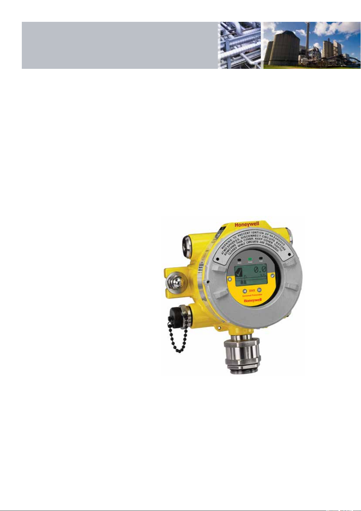
XNX Universal Transmitter
A universal transmitter
compatible with all
Honeywell Analytics gas
sensor technologies
Page 2
XNX Universal Transmitter
Flexible
• Compatible with all Honeywell Analytics
gas sensors
• Allows selection of best sensor
technology for each application
• Choice of all industry standard output signals
• Ability to adapt configuration as site
needs change
• Future-proofed for any new output standards
Common Transmitter Platform
• Simplified and reduced cost of installation
• Reduced training time and cost
• Less chance of misinterpreting messages
• Less chance of incorrectly changing settings
• Reduced maintenance, spares, stock
and cost
Global Approvals
• European, US and Canadian
• Compliant with ATEX, UL and CSA standards
• ATEX, UL and CSA performance approval
• IEC61508 SIL 2
Easy to Use
• Easy read multilingual backlit LCD with text,
bar graph, digits and icons
• Local or remote sensor mounting options
• Selectable sink, source or isolated
4-20mA output to suit preferred
wiring topology
• HART® communications as standard for
remote diagnostics/configuration
Reduced Operational Costs
• Fully configurable via non-intrusive
magnetic switches
• No hot work permit needed
• Hot swap toxic and Oxygen sensor cartridges
• Serviceable catalytic and IR sensors
• Auto-inhibit during maintenance
Friendly Installation
• Integral surface mounting lugs or optional
pipe or ceiling mounting brackets
• 5 x M25 or ¾” NPT cable/conduit/sensor
entries
• Plug-in ‘POD’ module removes to give access
to terminal area
• Removable plug/socket type terminal blocks
for ease of wiring
Typical Applications
• Offshore oil and production platforms
• Oil and gas exploration and drilling
• Refineries
• Chemical and petrochemical plants
• Onshore oil and gas terminals
• Gas transmission
• Power stations
XNX is an extremely flexible transmitter
that can be configured to accept an input
from any of the Honeywell Analytics range
of gas sensor technologies. It can also
be configured to provide a wide variety
of industry standard output signals.
This enables users to have a single type
of interface to all their gas detection needs,
even when different types of detectors are
employed, to most effectively address the
different gas detection applications on site.
The most effective gas detection systems often
employ a variety of detection technologies
including point flammable detectors (both
catalytic and infrared type), toxic and Oxygen
electrochemical cell type detectors and open
path infrared detectors. XNX provides a
common transmitter interface to all of these
and can be configured to provide industry
standard signal outputs to match the individual
requirement of each application or the preferred
site standard. If site output standards change,
XNX can be reconfigured to provide the new
required output. XNX has also been futureproofed by having the ability to have other
output modules fitted as new output standards
are developed and adopted by industry.
Having a common transmitter platform for
all your gas detectors brings further benefits.
Common tools and installation methods
simplifies and reduces cost of installation.
The common user interface makes operation
faster to learn and easier to navigate, thus
reducing time needed for training as well as
reducing the chance of incorrectly interpreting
messages or incorrectly changing settings.
Common spare parts also mean reduced
maintenance spares stock levels and cost for
all detectors.
XNX allows you to apply the most appropriate
gas detection technologies for each application,
standardise the interface to those detectors and
has the flexibility to provide the required signal
outputs. With XNX the answer is always yes.
Page 3

XNX Universal Transmitter
Inputs
HT
IR Point
EC
IR Open Path
XNX
Outputs
Foundation Fieldbus™
HART
Modbus
4-20mA
Relays
®
mV
X
XNX Transmitter
XNX has Worldwide hazardous area and
performance approvals and is housed in
a flameproof enclosure that is available in
either painted marine grade aluminum alloy
or stainless steel 316 versions. A large backlit
multilingual LCD clearly indicates the unit’s
status using a combination of text, digits and
icons. Users can modify its operation using
the LCD and magnet switches without ever
needing to open the unit. An optional local
IS HART® terminal port is also available.
Both enable one man, non-intrusive, operation
and reduce routine maintenance time and
costs. Local LEDs are also provided to indicate
the unit’s status at a glance.
N X
XNX Transmitter Sensor Compatibility
XNX is compatible with all of the
Honeywell Analytics range of industrial fixed
gas sensors including Searchline Excel,
Searchpoint Optima Plus, Sensepoint (HT and
PPM) and Model 705. For further information
on these sensors, please refer to their individual
datasheets.
XNX with Searchpoint Optima Plus
The Multi Purpose Detector (MPD) is a
serviceable stainless steel sensor housing with
plug-in catalytic and infrared sensor cartridges.
The catalytic sensors measure flammable
gases in the range 0-100%LEL and the
infrared sensors measure Hydrocarbons in the
range 0-100%LEL, or Methane 0-100%LEL
(or 0-5%Vol) and CO2 0-5%Vol. See the
specifications section for full details of the
MPD sensor.
The XNX EC sensor is also a serviceable
stainless steel sensor with a wide range of toxic
and Oxygen plug-in sensor cartridges. The XNX
EC sensor interface to the XNX transmitter is
intrinsically safe, allowing the sensors to be
‘hot swapped’ without the need for a hot work
permit. This reduces the cost of ownership
by reducing the cost and time to service
the detector.
XNX MPD Sensor
XNX EC Sensor
Page 4
XNX Universal Transmitter
XNX Transmitter
Configuration
XNX has three basic personalities
(configurations) which support different
types of sensor. The personality boards and
optional output interfaces are enclosed in
the electronics POD (Personality, Options
and Display). The POD determines the
XNX transmitter behaviour based on the
sensor type attached to it and the selected
output options.
The mV (millivolt) personality is used for all
mV signal input sensors including MPD,
Sensepoint HT, PPM and the Model 705.
The EC (Electrochemical cell) personality is
for use with the XNX EC toxic and Oxygen
sensors. The IR (infrared) personality is for
use with the Searchline Excel open path and
Searchpoint Optima Plus point infrared gas
detectors.
The table below shows the three basic XNX
transmitter configurations and the sensors
each supports.
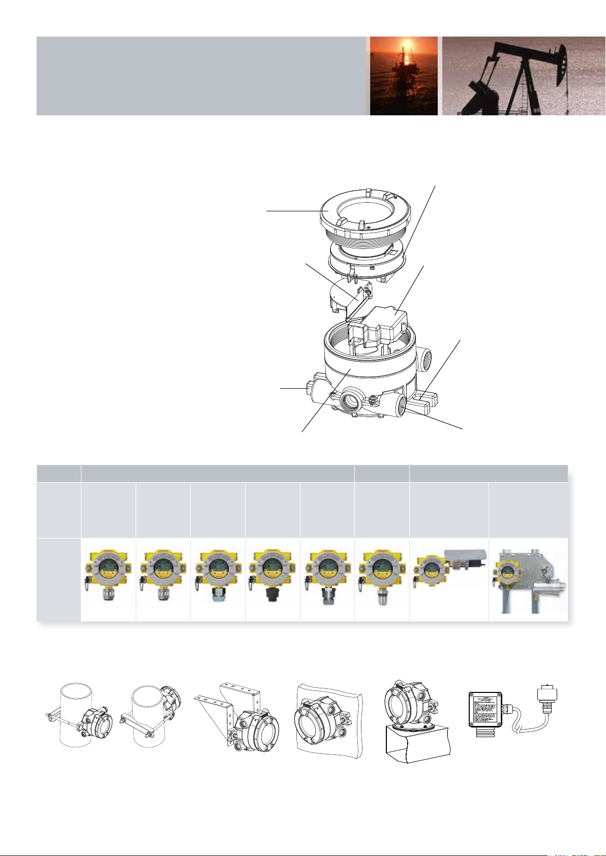
XNX Transmitter Main Components
POD - Personality, Options
and Display module
Cover
Intrinsically Safe
(IS) barrier for
Optional Local
®
Interface
HART
Optional Local IS
HART® input port
location (if fitted)
Enclosure
Intrinsically Safe (IS) barrier for
electrochemical sensor interface
(when equipped)
Mounting lugs (x2)
M25 or ¾”NPT
entries (x5)
Personality XNX mV XNX EC XNX IR
Sensors
Supported
Product
Image
MPD
Flammable
Catalytic
MPD
Flammable
Infrared
(Flam
and CO2)
Sensepoint HT
(High
Temperature)
Sensepoint
PPM
Model 705 HT
(High
Temperature)
XNX Toxic
and Oxygen
Sensors
Searchpoint
Optima Plus
Mechanical Installation Options
Searchline Excel
Vertical or Horizontal Pipe Mounted
(Using Optional Pipe Mounting Bracket)
Note: Other sensor accessories available dependent on sensor type. Contact Honeywell Analytics for further details.
Ceiling Mount
Surface Mounted Duct Mounted Optional remote sensor
mounting kit for XNX EC
sensor
Page 5

Installation
Outline Installation Dimensions
XNX has two integral mounting lugs on the transmitter body. The transmitter may be fixed directly to a surface, or to a horizontal or vertical pipe/
structure, Ø100-150mm (Ø4 to 6”) using a U bolt and pipe mounting bracket. Below are surface mounted outline installation dimensions for the
different XNX configurations.
Note: All dimensions are typical and are in millimeters. There are small differences in size between the aluminium version (shown) and stainless steel version. This does not effect the location of
the mounting holes.
197
170
142
197
170
142
93
220
80
93
XNX with MPD Sensor
43
14
153
Note: When fitting the Storm Baffle accessory (2108B0280) to the Searchpoint Optima Plus, please use the Fitting Kit (2108B0270).
XNX with EC Toxic and Oxygen Sensor
43
14
153
123 (max)
17
33
123 (max)
17
XNX with Sensepoint PPM Sensor
153
80
229
33
197
170
142
43
14
93
80
123 (max)
17
33
Page 6

Installation
Outline Installation Dimensions
XNX IR with Searchpoint Optima Plus
187
165 MIN F. C.
302 (6” Pipe)
388
204 (2” Pipe)
197
114
123 (Max)
214
281 (MAX)
XNX IR with Searchline Excel
161
Pipe Mounted
Pipe Mounted
M25
Ceiling Mounted
488328
5 - 40m
294
Open Path Range
300 (Approx)
294
300 (Approx)
488
417
Pipe Mounted Surface Mounted
M20
Page 7

Installation
Outline Installation Dimensions
XNX with Remote Sensepoint HT and Feel Junction Box
197
160
142
125 CRS
123
43
14
153
XNX with Remote Sensepoint Model 705 HT and Junction Box
43
14
153
197
160
142
93
80
Certified UL high
temperature junction box
Certified HT cable gland and
cable (not supplied)
93
80
Model 705 HT
sensor
122
161
¾" NPT cable entries fitted
with certified blanking plugs
¾" NPT entry
for sensor
190
Wiring Schematics
The XNX transmitter may be configured current source, sink or isolated. These options are offered to allow greater flexibility in the type of control
system that it can be used with. Source/sink/isolated is selectable via the switch located on the back side of the POD.
Controller Detector
+VE
1
Signal -mA
2
R
L
-VE
3
+V
1-1
1-6
-V
1-3
XNX Source Configuration
Note: Terminate cable screen at the detector or the controller, not both.
Controller Detector
+VE
1
R
L
Signal +mA
2
-VE
3
+V
1-1
1-5
-V
1-3
XNX Sink Configuration
Controller Detector
+V1
+V2
-V2
-V1
+V
1-1
+mA
1-5
-mA
1-6
-V
1-3
XNX Isolated Configuration
Page 8

Electrical
Electrical
XNX is designed for use in potentially explosive atmospheres. As such, installation should follow national guidelines using suitable mechanically
protected cable and glands (M25 or ¾” NPT) or conduit. Use 0.5mm2 (20AWG) to 2.5mm2 (~13AWG) cross sectional area cable as needed to
ensure minimum operating voltage at the detector, depending on installed cable length. Five M25 (ATEX/IECEx certified version) or ¾”NPT entries
(UL/CSA version) are provided. Entries are also used for either locally mounting a sensor or for accepting the cable/conduit from a remotely
mounted sensor.
Typical Maximum Cable Lengths
The maximum cable length between a
controller and detector is dependent upon:
• The minimum guaranteed supply voltage
from the controller
• The minimum operating voltage of the
detector
• The maximum current draw of the
detector
• The input impedance of the controller
• The resistance of the cable
Terminals on POD Module
All sensor connections and option module
connections are made at the terminal blocks
mounted on the rear of the removable POD
module.
The terminals provided are dependent on
which of the three basic personalities have
been selected plus the options selected.
The tables below show the different terminal
connections for each of the available POD
personality boards and options boards.
S1 S2
Down Up
Source
UP Down
Sink
Isolated
Down Down
The typical maximum cable length table (right)
is for an XNX mV with an MPD catalytic sensor
or an XNX EC with an XNX EC sensor fitted.
It also assumes a single transmitter being
powered from a PSU. Refer to the manual for
examples of other variants and cable topology.
Example mV POD with Relay Option
TB4
Remote
Reset SW
Relay Ratings
250VAC 2A
24VDC 5A
NC
3-1
C
3-2
NO
3-3
NC
3-4
3-5
C
3-6
NO
3-7
NC
3-8
C
Fault Level 2 Level 1
NO
3-9
TB-3 RELAY
Warning: Power
externally supplied.
Disconnect at source
prior to servicing.
Cable Size Max Cable Distance
2
(18AWG*) 347m (1140')
1.0mm
2
(16AWG*) 551m (1810')
1.5mm
2
(14 AWG*) 880m (2890')
2.0mm
2
(12AWG*) 1408m (4620')
2.5mm
*nearest equivalent
Isolated Selection Switches
LOCAL
20 mA
Operation
S1
S2
16-32 VDC
6.5W max.
HART
Sensepoint
Source
Sink
Isolated
4-20mA
+mA 1-5
-mA 1-6
MPD, 705
Sense
J1
HART
S1
+V 1-1
1-2
-V 1-3
1-4
1-7
0v 1-8
Ref 1-9
S2
mV TB-1
Meters (Feet)
Sink/Source/
Options Boards
Terminal Relay Modbus RTU Foundation Fieldbus
TB3 Marking Connection Marking Connection Marking Connection
3-1 NC Alarm 1 Normally Closed + Power In + F+ FF Data In +
3-2 C Alarm 1 Common + Power Out + F+ FF Data Out +
3-3 NO Alarm 1 Normally Open - Power In - F- FF Data In 3-4 NC Alarm 2 Normally Closed - Power Out - F- FF Data Out 3-5 C Alarm 2 Common A Modbus A In FS FF Shield In
3-6 NO Alarm 2 Normally Open A Modbus A Out SS FF Shield Out
3-7 NC Fault Normally Closed B Modbus B In
3-8 C Fault Common B Modbus B Out
3-9 NO Fault Normally Open S Modbus Drain In
3-10 - - S Modbus Drain Out
TB4 Marking Connection
Remote reset switch
Remote reset switch
Personality Boards
Terminal Marking Connection
TB1 EC mV IR
1-1 +V +V +V +VE Supply (18-32VDC)
1-2 +V +V +V +VE Supply (18-32VDC)*
1-3 -V -V -V -VE supply (0VDC)
1-4 -V -V -V -VE supply (0VDC)*
1-5 +mA +mA +mA Current & HART output 4-20mA +
1-6 -mA -mA -mA Current & HART output 4-20mA 1-7 - Sense +Ir Sensor Connection
1-8 - 0V -Ir Sensor Connection
1-9 - Ref Sig Sensor Connection
TB2 EC mV IR
2-1 - - Com A Optima/Excel Modbus A Comms
2-2 - - Com B Optima/Excel Modbus B Comms
*Terminal block jumper required
Page 9

Technical Summary
XNX Transmitter
Use High specification universal transmitter for use with a wide range of Honeywell Analytics local or remote gas detectors for the detection of flammable, toxic and Oxygen
gas hazards. Suitable for use in Zone 1 and 2 or Zone 21 and 22 hazardous areas, and North American Class I and II Division 1 or 2 areas.
Construction
Material Housing: 5-coat marine finish painted aluminium alloy or 316 stainless steel
Weight (Approx.) Aluminium alloy: 2.8kg (6.2lbs). 316 stainless steel: 5kg (11lbs)
Mounting Surface mount via integral mounting lugs. Optional pipe mounting kit suitable for Ø100mm to 150mm (Ø4” to 6”) pipe. Optional ceiling mounting bracket
Entries 5 conduit/cable entries (2 right, 2 left, 1 bottom). Entry size M25 for ATEX/IECEx versions or ¾"NPT for UL/CSA certified versions
Dimensions 160mm x 197mm x 114mm (6.1" x 7.8" x 4.5")
Environmental
IP Rating IP66 in accordance with EN60529:1992. NEMA 4X
Operating Temperature -40ºC to +65ºC (-40ºF to +149ºF)
Operating Humidity 0-99%RH (non condensing)
Operating Pressure 90-110kPa
Storage Conditions -40ºC to 75ºC (-40ºF to 167ºF), 0-99% non-condensing
Electrical
Input Voltage Range EC and mV versions 16 to 32Vdc, IR version 18 to 32 Vdc (24Vdc nominal)
Max Power Consumption XNX EC (Toxic): 6.2 watts
XNX mV (Catalytic or IR cell): 6.5 watts
XNX IR with Searchpoint Optima Plus: 9.7 watts
XNX IR with Searchline Excel Receiver: 13.2 watts
®
Current Output Fully configurable isolated 4-20mA & HART
supplied as standard
Default current output settings: HART
≥0.0<1.0mA Fault 3mA Fault/Warning
4.0 mA to 20.0mA Normal gas measurement 4-20mA Normal gas measurement
2.0 mA or 4.0 mA (17.4mA) Inhibit (during configuration/user settings) 22.0mA Maximum over range
The available output range for Inhibit, Warning, Beam Blocked and Low Signal is from 1 to 4mA. For an over range condition, the range is 20 to 22mA
4-20mA Signal Accuracy +/-1% Full Scale
Functions Supported
®
by HART
Gas reading
Gas name and units of measurement
4-20mA signal level
General/device information
Installation
Configuration
Forcing of 4-20mA output
Terminals Cage style pluggable with retaining screws for wire diameter 0.5mm
Certification
European ATEX:
II 2 (1) G Ex d [ia IIC Ga] IIC T4/T6 Gb II 2 (1) D Ex tb [ia IIIC Da] IIIC T85 Db
International IECEx: Ex d [ia IIC Ga] IIC T4/T6 Gb Ex tb [ia IIIC Da] IIIC T85 Db
North American UL: Class I, Div 1, Groups A, B, C, and D; Class II, Div. 1 Groups F & G / Class 1, Zone 1 Groups IIB + H2; Class II, Zone 20 & 21
FM: AEx D [ia IIC] IIB + H2 T6 -40°C ≤Tamb ≤65°C
Canadian CSA: Class I, Div 1, Groups B, C, and D; Class II, Div. 1 Groups F & G / Class I, Zone 1 Groups IIB + H2
EMC EN50270:2006 EN61000-6-4:2007
Performance Europe – ATEX, EN45544, EN50104, EN50271:2010, EN13980, EN60079-29-1
North America – UL 913, UL 1203, CSA 22.2 No. 152
IEC61508 (SIL Assessment, SIL 2), IECEx OD 005
®
Local IS HART
Port (Optional)
Description Provides externally accessible IS connections to the XNX transmitter to enable ‘hot’ connection of HC275/375 HART
Installation Fitted to one of the cable entries on the XNX transmitter. Option can be factory fitted or in the field by a qualified service engineer
Environmental Protection Port protected by cover to IP66/67 when not in use
Relay Module (Optional)
Description Provides three fully user configurable relay outputs that can be switched based on the current gas level and/or status of the transmitter. Provides 2 x SPCO alarm and
1 x SPCO fault relay. Mutually exclusive with Modbus and/or Foundation Fieldbus
Rating Maximum: 240VAC, 5A (non inductive load) Minimum: 5V, 10mA (non inductive load)
Installation Option can be factory installed in display module or in the field by a qualified service engineer
output module providing current sink, current source and isolated modes of operation (supports HART® 6.0 protocol)
®
mode:
Detailed sensor information including:
Optical signal level
Dynamic reserve (Searchline Excel only)
Raw reading
Calibration and configuration status
Detailed fault and warning information
Fault and alarm history
Zero calibration
24V supply voltage
Temperature
2
to 2.5mm2 (approx. 20AWG to 14AWG)
®
or equivalent hand held configurator
TM
options
Page 10

Technical Summary
Foundation Fieldbus™ Module (Optional)
Description Foundation Fieldbus™ output for connection to a multi-drop H1 network. Mutually exclusive with relays and/or Modbus options
Installation Option can be factory installed in display module or in the field by a qualified service engineer
Connections Sig+, Sig- and Screen
Physical Layer Conforms to IEC 1158-2 and ISA 50.02, 31.25Kbits/s
Maximum No. of Nodes 32
Functions Supported
Modbus RTU Module (Optional)
Description The Modbus output module provides an isolated RS485 output to enable the connection of the XNX transmitter to a multi-drop Modbus network. Mutually exclusive
with relays and/or Foundation Fieldbus
Installation Option factory installed in display module or in the field by a qualified service engineer
Connections RS485+, RS485-, Drain
Physical Layer Isolated RS485, 1200 to 19.2K baud
Maximum No. of Nodes 254 XNX compatible transmitters only
Protocol Modbus RTU
Functions Supported As per Foundation Fieldbus™ Module (Optional) - see above
XNX EC Sensor
Gas Cartridge P/N Selectable Full
O
H
H
H
Oxygen XNXXSO1SS n/a 25.0 %Vol 3.5 %Vol n/a
2
S (LoLo) Hydrogen Sulphide XNXXSH3SS n/a 15.0ppm 1.0ppm n/a
2
S (Lo) Hydrogen Sulphide XNXXSH1SS 10.0 to 50.0ppm 15.0ppm 1.0ppm 0.1ppm 10ppm <20 <30 <+/-0.3ppm -40°C / -40°F 55°C / 131°F**
2
S (Hi) Hydrogen Sulphide XNXXSH2SS 50 to 500ppm 100ppm 1ppm 10ppm 50ppm <20 <30 <+/-5ppm -40°C / -40°F 55°C / 131°F**
2
CO Carbon Monoxide XNXXSC1SS 100 to 500ppm 300ppm 5ppm 100ppm 100ppm <15 <30 <+/-2ppm -40°C / -40°F 55°C / 131°F**
SO
(Lo) Sulphur Dioxide XNXXSS1SS 5.0 to 20.0ppm 15.0ppm 0.6ppm 5.0ppm 5.0ppm <15 <30 <+/-0.3ppm -40°C / -40°F 55°C / 131°F**
2
SO
(Hi) Sulphur Dioxide XNXXSS2SS 20.0 to 50.0ppm 50.0ppm 1.5ppm 10.0ppm 25ppm <15 <30 <+/-0.6ppm -40°C / -40°F 55°C / 131°F**
2
NH
(Lo) Ammonia XNXXSA1SS 50 to 200ppm 200ppm 6ppm 50ppm 100ppm <60 <180 <+/-4ppm -20°C / -4°F 40°C / 104°F
3
NH
(Hi) Ammonia XNXXSA2SS 200 to 1,000ppm 1,000ppm 30ppm 50ppm 300ppm <60 <180 <+/-20ppm -20°C / -4°F 40°C / 104°F
3
CL
(Lo) Chlorine XNXXSL2SS n/a 5.00ppm 0.15ppm n/a 2.0ppm <20 <60 <+/-0.2ppm -10°C / 14°F 55°C / 131°F
2
CL
(Hi) Chlorine XNXXSL1SS 5.0 to 20.0ppm 5.0ppm 0.6ppm 5.0ppm 2.0ppm <20 <30 <+/-0.2ppm -10°C / 14°F 55°C / 131°F
2
CIO
Chlorine Dioxide XNXXSX1SS n/a 1.00ppm 0.03ppm n/a 0.5ppm <30 <120 <+/-0.03ppm -20°C / -4°F 55°C / 131°F
2
NO Nitrogen Monoxide XNXXSM1SS n/a 100ppm 3ppm n/a 50ppm <15 <30 <+/-2ppm -20°C / -4°F 55°C / 131°F
NO
H
H
Nitrogen Dioxide XNXXSN1SS 5.0 to 50.0ppm 10.0ppm 1.5ppm 5.0ppm 5ppm <15 <30 <+/-0.2ppm -20°C / -4°F 55°C / 131°F
2
(Lo) Hydrogen XNXXSG1SS n/a 1,000ppm 30ppm n/a 500ppm <60 <90** <+/-8ppm -20°C / -4°F 55°C / 131°F
2
(Hi) Hydrogen XNXXSG2SS n/a 10,000ppm 300ppm n/a 5000ppm <15 <30 <+/-150ppm -20°C / -4°F 55°C / 131°F
2
HF Hydrogen Fluoride
PH
Phosphine
3
HCN Hydrogen Cyanide XNXXSY1SS n/a 30.0ppm 1.0ppm
F
O
Fluorine
2
Ozone
3
ETO Ethylene Oxide
XNX Multi Purpose Detector (MPD)
Sensor
Type
IR CO2 Carbon Dioxide 1.00 to 5.00%Vol 5.00%Vol 1.00%Vol 1.50 to 3.5%Vol Carbon Dioxide 2.5%Vol <60 ±5% of FS -20°C/-4°F +50°C/+122°F
IR CH4 Methane
IR HC Hydrocarbons
Catalytic Flammables 20 to 100%LEL 100%LEL 10%LEL 30 to 70%LEL Methane 50%LEL <30 ±5% of FS -40°C/-40°F +65°C/+149°F
NOTES
Data taken at ambient conditions of 20°C, 50% RH. Data represents typical values of freshly calibrated sensors without optional accessories attached. *Accuracy at 10% of default full scale (typical A1 alarm) of applied gas, or minimum
(whichever is greater). Measured using calibration flow housing at calibration flow rate. Performance figures are applicable between 10 and 90% of full scale. Performance figures are measured by test units calibrated at 50% of full scale.
Contact Honeywell Analytics for any additional data or details. **Accuracy for operation between -20°C and -40°C is +/-30% of applied. Operation at these temperatures continuously (exceeding 12 hours) may cause deterioration in
sensor performance and shorten sensor life.
#
Propane sensor with linear cross reference for Ethylene, n Butane and n Pentane.
Contact Honeywell Analytics for any additional data or details.
Target Gas User Selectable
#
Gas reading
Gas name and units of measurement
Instrument status (OK, warning, fault,
over-range)
General/Device Information
Remote zero and span calibration
(detector dependent)
Scale Range
Default
Range
Detailed sensor information Including:
Optical Signal Level
Dynamic reserve (Searchline Excel only)
Raw reading
24V supply voltage
Temperature
Calibration and configuration status
TM
options
Lower
Detectable
Steps Selectable Cal
Limit
Gas Range
20.9 %Vol (Fixed)
Detailed Fault and Warning Information:
Fault and alarm history
Zero calibration
Default
Response
Cal Point
(T50) sec
20.9 %Vol T20 <10 <30 <+/-0.6 %Vol -30°C / -34°F 55°C / 131°F
Time
Response
Time
(T90) sec
Accuracy* Operating Temperature
Min Max
10ppm <20 <40 <+/-0.3ppm -40°C / -40°F 55°C / 131°F**
30 to 70% of selected full scale range
XNXXSF1SS
XNXXSP1SS
XNXXSU1SS
XNXXSZ1SS
XNXXSE1SS
Full Scale Range
n/a
n/a
n/a
n/a
20.0 to 50.0ppm
12.0ppm 0.4ppm
1.20 ppm 0.04ppm
4.00ppm 0.36ppm
0.400ppm 0.032ppm
25.0ppm 1.0ppm
Default Range Steps User Selectable
1.00 to 5.00%Vol 5.00%Vol 1.00%Vol 1.50 to 3.5%Vol
20 to 100%LEL 100%LEL 10%LEL 30 to 70%LEL 50%LEL ±5% of FS
n/a
n/a
n/a
n/a
n/a
5.0ppm
Cal Gas Range
5.0ppm 120 <240 <+/-0.5ppm -20°C / -4°F 55°C / 131°F
0.5ppm <15 <30 <+/- 0.02ppm -20°C / -4°F 40°C / 104°F
10.0ppm <35 <200 0.4ppm -20°C / -4°F 55°C / 131°F
2.00ppm <5 <30 0.03ppm -20°C / -4°F 55°C / 131°F
0.200ppm <15 <60 0.003ppm -20°C / -4°F 55°C / 131°F
10.0ppm <40 <125 0.3ppm -20°C / -4°F 55°C / 131°F
Primary Cal
Gas
Methane
Default Cal
Point
2.5%Vol
Response
Time (T90)
secs
<30
Accuracy Operating Temperature
±5% of FS
-20°C/-4°F +50°C/+122°F
Min Max
20 to 100%LEL 100%LEL 10%LEL 30 to 70%LEL Propane 50%LEL <30 ±5% of FS -20°C/-4°F +50°C/+122°F
Page 11

Ordering Information
Ordering Information
Standard Supply: The XNX universal transmitter is supplied complete with integral wall mounting lugs, 5 x M25 cable entries (ATEX/IECEx) or 5 x 3/4" NPT conduit entries (UL/CSA), Magnetic wand/
screwdriver, Allen key, 3 x blanking plugs, quick start guide and manual CD. MPD or XNX EC sensors and cartridges are supplied fitted to the bottom entry if ordered. Other sensors are supplied separately.
Default settings are configured according to specified personality type (mV, EC or IR) and selected output options.
XNX- -
Approval Entry Type Material Personality Option Local HART Sensor and Range
A
ATEX/IEC
U
UL- CSA
M
M25
T
¾"NPT
Example part number:
XNX-AMSV-NNCB1
XNX transmitter with HART® over 4-20mA output
ATEX/IEC approved
A
Aluminium
S
316
Stainless
Steel
E
c
Interface for Electrochemical Cartridges
(Includes IS Barrier
and Adaptor) For
use with XNX Toxic
and Oxygen Sensors
I r
Interface for
infrared Products
Use with Searchline
Excel, Searchpoint
Optima and Generic
4-20mA inputs
-
5 x M25 entries
painted 316 stainless steel
mV version
no output options
no local HART
Including MPD sensor. catalytic sensor 0-100%LEL.
m V
Interface for
milli-Volt sensors
For use with MPD,
Sensepoint (and
Model 705) HT and
PPM Sensors
Shipping Details
Shipping Carton L370mm (14.6”) x W280mm (11”) x D180mm (7.1”).
Packed weight (Approx.) Aluminium version 4.4kg (9.7lbs), stainless steel version 6.8kg (15lbs)
Optional Accessories
Pipe Mount Kit
1226A0358 For use on pipes from 50-100mm (2-6 inches) in diameter. The kit includes: Pipe mount bracket, (2) carriage bolts, nuts and lock washers.
N
No Option
installed
R
Relay Option
M
Modbus Option
F
Foundation
FieldbusTM
Option
N
No Option
installed
H
Local Hart
NOTES
Certain combinations not available e.g. ATEX with
¾" NPT entries. Check price list for valid configurations.
Order sensors other than MPD separately and select'NNN' for
sensor and range.
Species the MPD sensor
None
NNN
Catalytic Bead
CB1
IR Hydrocarbons
IF1
(0-100%LEL Propane)
IR 0-100%LEL
IV1
(or 0-5%Vol.) Methane
IR Carbon Dioxide
IC1
0-5%Vol.
Remote EC Sensor
Mounting Kit
Ceiling Mount Bracket
Kit
Duct Mount Kit
MPD Interface Adapter
Calibration
Gas Flow Adapter
Weatherproof Cap
Collecting Cone
Remote Gassing Kit
S3KRMK
1226A0355 The optional ceiling mount bracket kit allows XNX to be mounted to a ceiling. The kit includes: (2) stainless steel ceiling mount brackets, bolts and nuts.
S3KDMK
1226A0382
S3KCAL XNX EC
1226A0411 MPD
02000-A-1645 Sensepoint
00780-A-0035 705
Included XNX EC
02000-A-1640 MPD
02000-A-1640 Sensepoint
00780-A-2076 705
SPPPCC XNX EC
02000-A-1642 MPD
02000-A-1642 Sensepoint
02000-A-1642 705
1226A0354
The remote sensor mounting kit (S3KRMK) allows the XNX EC sensors to be remotely mounted via an IS cable kit, up to 15 meters (50 feet) from the
transmitter. The kit includes 15 meters of shielded cable, cable glands and remote terminal box. The cable can be cut to the required length and terminated
at the remote terminal box.
The duct mounting kit (S3KDMK) can be used with the EC sensor to allow detection of flammable O
the MPD interface adapter (1226A0382), the duct mounting kit can accommodate the MPD to detect flammable gases in a duct application. The duct mount
kit includes the adapter, gasket and required fasteners. The MPD interface adapter includes only the adapter and requires the S3KDMK duct mount kit.
The calibration gas flow adapter is used to apply calibration test gas to the sensor. It push fills onto the bottom of the sensor and can
be fitted without removing the weatherproof cover.
The weatherproof cap protects the XNX sensors from harsh weather.
The collecting cone improves detection of lighter-than-air gasses such as Hydrogen and Methane.
The remote gassing kit enables gas to be applied remotely for performing functional response checks.
Kit includes 50' Teflon
your device.
®
tubing, mounting bracket, tube cap and device adapters in ¼" and 1/8" ID to attach to bump test ports on the weatherproof cap of
, CO, H2 and H2S gasses in ducts. When combined with
2
Page 12

Honeywell Analytics Gas Detection
Honeywell Analytics is able to provide gas detection solutions to meet the requirements of all
applications and industries. Contact us in the following ways:
Headquarters
Europe, Middle East, Africa
Life Safety Distribution AG
Javastrasse 2
8604 Hegnau
Switzerland
Tel: +41 (0)44 943 4300
Fax: +41 (0)44 943 4398
gasdetection@honeywell.com
Customer Service:
Tel: 00800 333 222 44
Tel: +41 44 943 4380 (Alternative number)
Fax: 00800 333 222 55
Middle East Tel: +971 4 450 5800 (Fixed Gas Detection)
Middle East Tel: +971 4 450 5852 (Portable Gas Detection)
(Freephone number)
Technical Support Centres
Honeywell Analytics Ltd.
4 Stinsford Road
Nufeld Industrial Estate
Poole, Dorset, BH17 0RZ
United Kingdom
Tel: +44 (0) 1202 645 544
Fax: +44 (0) 1202 645 555
Honeywell Analytics
ZAC Athélia 4 - 375 avenue du Mistral
Bât B, Espace Mistral
13600 La Ciotat
France
Tel: +33 (0) 4 42 98 17 75
Fax : +33 (0) 4 42 71 97 05
Americas
Honeywell Analytics Distribution Inc.
405 Barclay Blvd.
Lincolnshire, IL 60069
USA
Tel: +1 847 955 8200
Toll free: +1 800 538 0363
Fax: +1 847 955 8210
detectgas@honeywell.com
Honeywell Analytics
Elsenheimerstrasse 43
80687 München
Germany
Tel: +49 89 791 92 20
Fax: +49 89 791 92 43
Asia Pacic
Honeywell Analytics
Asia Pacic
#701 Kolon Science Valley (1)
43 Digital-Ro 34-Gil, Guro-Gu
Seoul 152-729
Korea
Tel: +82 (0) 2 6909 0300
Fax: +82 (0) 2 2025 0328
India Tel: +91 124 4752700
analytics.ap@honeywell.com
Honeywell Analytics
P.O. Box-45595
6th Street
Musaffah Industrial Area
Abu Dhabi
UAE
Tel: +971 2 554 6672
Fax: +971 2 554 6672
EMEA: HAexpert@honeywell.com
US: ha.us.service@honeywell.com
AP: ha.ap.service@honeywell.com
www.honeywellanalytics.com
www.raesystems.com
Honeywell Analytics
Experts in Gas Detection
Please Note:
While every effort has been made to ensure accuracy in this publication, no responsibility can be accepted for errors or
omissions. Data may change, as well as legislation, and you are strongly advised to obtain copies of the most recently
issued regulations, standards, and guidelines. This publication is not intended to form the basis of a contract.
12550_H_XNX_DS01078_V5_EMEA
09/15
© 2015 Honeywell Analytics
 Loading...