

Page 1

XLS80e
Panel Configuration
Manual
March 2007, Issue 9
Page 2
i
XLS80e Fire Alarm Control Panels
Honeywell, Issue 9
March 2007
Quick Contents Reference by
Section
XLS80e
0 1
2 3
4 5
6 7
8 9
User Menu:
3:Log/display/print menu
4:Set Clock
5:View Alarm Count
6:
Service Mon 01-May-2000 11:20:07
Configuration
User Menu:
1:
2:Disable/enable
3:Log/display/print menu
4:Set Clock
Service Mon 01-May-2000 11:20:07
Test
DISPLAY:
SUMMARY - SEE SECTION
DETAILED DESCRIPTION OF MENUS, SEE SECTION:
4
CONFIGURATION MENU:
OVERVIEW - SEE SECTION
DETAILED DESCRIPTIONS, SEE SECTION:
3
12
12
10
ALSO:
TIME-OF-DAY - SEE SECTION
SENSITIVITY & DELAYS RECOMMENDATIONS - SEE SECTION
UPGRADING THE SOFTWARE - SEE APPENDIX
AVAILABLE LOOP DEVICES - SEE APPENDIX
XLSNET - SEE APPENDIX
9
13
1
2
3
POWER ON SEE SECTION 2
CONFIGURATION:
1:
2:Zone Text Editor
3:Panel Text Editor
4:Control Matrix Configuration
Service Mon 01-May-2000 11:20:07
Loop Device Configuration
5
6
7
CONFIGURATION:
4:Control Matrix Configuration
5:Network Configuration
6:Panel Settings
7:
Service Mon 05-DEC-2005 11:20:07
Virtual Point Configuration
14
8, 11
15
Page 3

ii
XLS80e Fire Alarm Control Panels
Honeywell, Issue 9
March 2007
Contents
1 Introduction 1
1.1 Associated Documents 1
1.2 System Design and Planning 1
1.3 Glossary of Icons 2
1.4 Software Version Number 4
1.5 EN54 Functions 4
1.6 Ancillary Functions 5
2 Power On/Start Up 7
3 Panel Configuration Overview 9
3.1 Where to Access the Configuration Actions 9
3.2 Configuration Actions 10
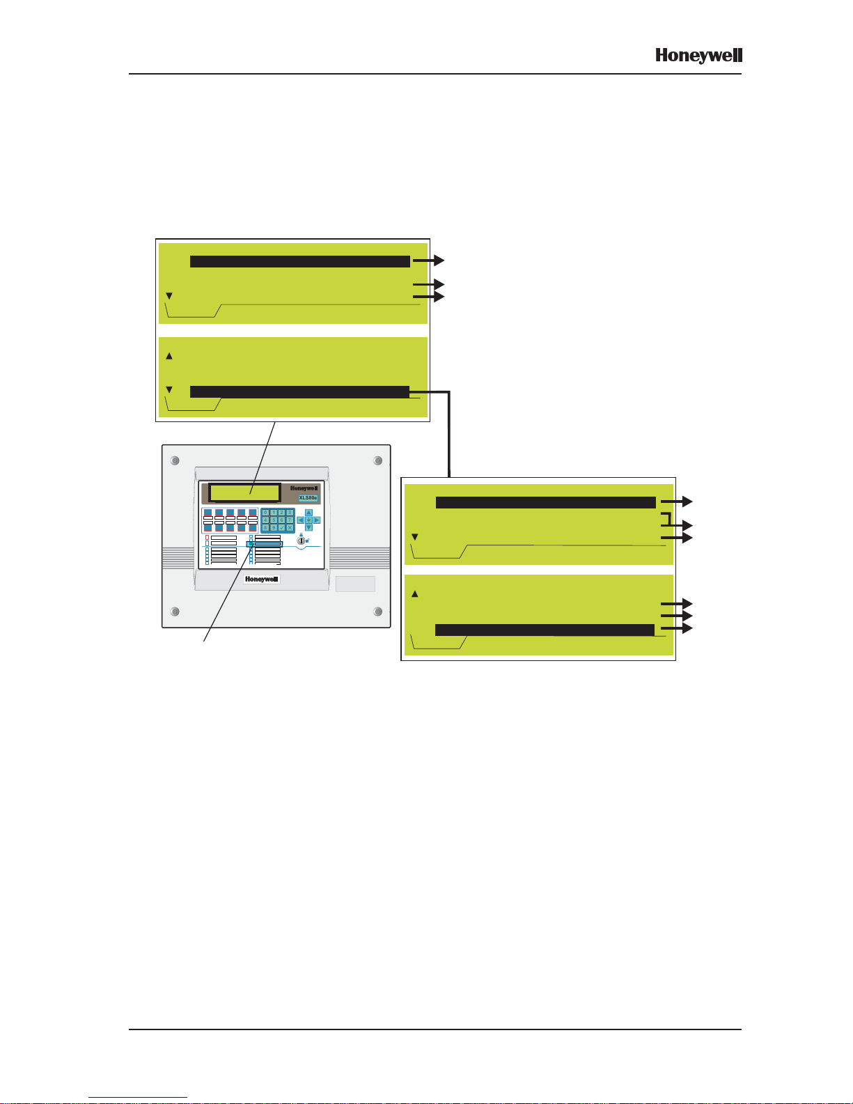
3.3 Using the Panel Controls and Indicators 11
3.3.1 Pushbuttons 11
3.3.2 Liquid Crystal Display 12
3.4 Using the Off-line Support Tool 13
3.5 Passcodes 13
3.6 Learn Devices on Loops 14
3.7 Configure Group of Devices 15
3.8 Configure Individual Device 15
3.9 Text Editing 16
3.10 Control Matrix 16
3.11 Time-of-Day 17
3.12 Setting the Clock 17
3.13 Panel Settings 17
3.14 System Networking 18
3.15 Delays 19
3.16 Virtual Point Configuration 19
4 The Display - Tabs, Events and
Menus 20
4.1 Introduction 20
4.1.1 Status: NORMAL 20
4.1.2 Tabs 20
4.1.3 Events 20
4.1.4 Menus 20
4.2 Tabs 21
4.3 Event Displays 22
Page 4

iii
XLS80e Fire Alarm Control Panels
Honeywell, Issue 9
March 2007
4.4 Menu Displays 25
4.4.1 To Display the User Menu 25
4.4.2 To Navigate Through the Menus 26
4.4.3 Menu Structure 27
5 Loop Device Configuration 29
5.1 Configure Individual Device 29
5.1.1 Select a Device 29
5.1.2 Change Device Configuration
- Sensors 31
5.1.3 MULTI, MCS & GAS Sensitivities 37
5.1.4 Change Device Configuration
- Modules 39
5.2 Configure Group of Devices 43
5.3 Learn Devices on Loops 45
5.3.1 Starting the Procedure 45
5.3.2 Run in Auto-Learn Mode 47
5.3.3 Run in Manual Learn Mode 49
5.3.4 Error Messages 49
5.3.5 End of Learn Process 50
5.4 Change Zone Number 50
6 T ext Editing 51
6.1 Text Editing Pushbuttons 51
6.2 The Character Set 52
6.3 Zone Text Editing 52
6.4 Panel Text Editing 53
7 Control Matrix 54
7.1 Introduction 54
7.1.1 EN54 Requirements 55
7.2 Input Categories 56
7.3 Output Categories 58
7.4 Output Modes 59
7.5 Review/Edit Control Matrix 61
7.5.1 Review Entries 61
7.5.2 Edit Entries 62
7.6 Defining a Control Matrix Entry 63
7.6.1 Input Definitions 63
7.6.2 Output Definitions 69
7.6.3 Completion of New Entry 75
7.7 Disablement/Enablement Function 76
Page 5

iv
XLS80e Fire Alarm Control Panels
Honeywell, Issue 9
March 2007
7.8 Extinguishing System Function 77
7.8.1 T ypes of Control Matrix Entry 77
7.8.2 Minimum Configuration 77
7.8.3 Device Selection 78
7.8.4 HOLD Options 78
7.9 Logic Operation with Transfer Flags 79
7.9.1 Example Logic Operations 79
7.10 Print Control Matrix 81
8 Change Passcode 82
8.1 Introduction 82
8.2 How to Change a Passcode 83
9 Time-of-day Programming 85
9.1 Time-of-day Program Editing 85
9.2 Manual Override 87
9.3 DISABLEMENT and
ENABLEMENT Override 88
9.4 MULTI Thermal-Only Mode 89
9.5 Link to Day/Night Switch 89
10 Setting the Clock 90
11 Panel Settings 91
11.1 Internal Buzzer Options 91
11.2 LED ‘Blinking’ Mode 92
11.3 Number of LOOPS on Panel 93
11.4 Pulsing Sounder Modes 94
11.5 Walk Test Options (MCP/Sounder) 94
11.6 Automatic Test Options 95
11.7 Disablement Options 95
11.8 Loop Options 97
11.9 Panel Functions 97
11.10 Access Level for MUTE BUZZER etc. 98
11.11 Unlatched Non-alarm Input Logging 98
11.12 Relay Circuits SILENCE Option 99
11.13 Mains/PSU Fault Delays 99
11.14 LCD Backlight ‘On’ Duration 100
11.15 Blank Lines Between Printed Events 100
11.16 Isolated RS232 Port Set-up 101
11.17 Diagnostic RS232 Port Set-up 102
11.18 Remote Fire Output Options 103
Page 6

v
XLS80e Fire Alarm Control Panels
Honeywell, Issue 9
March 2007
11.19 Day/Night Modes Configuration 104
11.20 Extinguishing System 105
11.21 Alarm Coincidence 106
11.22 Network Settings 107
11.23 Thermal Alarm Verification Time 107
12 User Menu at Level 3 Access 108
12.1 Control Output Tests 108
12.1.1 CMX Modules 109
12.1.2 Local Sounder Circuits 1 10
12.1.3 Relay Circuits 110
12.1.4 Virtual Output Points 111
12.1.5 Loop Sounders and Boosters 111
12.2 Bad Poll Log 112
12.3 Display Active Control Matrix Rules 112
12.4 Unconfigured Devices Scan Menu 112
12.4 Commissioning Mode for MCS Sensors 113
13 Sensitivity and Alarm Delay
Recommendations 114
13.1 Analogue Sensors Sensitivity 114
13.2 Analogue Device Verification 114
13.3 Module Delays 115
14 Master/Slave Network 116
14.1 Introduction 116
14.1.1 Number of Stations on Network 1 1 6
14.1.2 Number of Zones on Network 1 1 7
14.1.3 Information Distribution via Network 1 18
14.2 Network Configuration Procedures 119
14.2.1 Station Type 120
14.2.2 THIS Panel 121
14.2.3 Associate Repeaters with Panel 122
14.2.4 Completion of Network Configuration 122
14.3 Print Network Configuration 122
15 Virtual Point Configuration 123
15.1 Virtual Output Points 123
15.2 Virtual Input Points 124
15.3 Virtual Output Backup Sounder 124
Page 7

vi
XLS80e Fire Alarm Control Panels
Honeywell, Issue 9
March 2007
Appendix 1
Upgrading the Panel Software A1-1
Appendix 2
Available Loop Device Types A2-1
Appendix 3
XLSNET Network Configuration A3-1
Page 8
1 Honeywell, Issue 9
March 2007
XLS80e Fire Alarm Control Panels
1 Introduction
This manual provides recommended procedures
for the successful configuration of a complete
Honeywell XLS80e Series integrated Fire Control
System (including repeater panels). The
procedures also apply for XLS80e Series
stand-alone Fire Control units.
The XLS80e Series intelligent fire alarm
controllers are designed for use with
Honeywell’s range of addressable analogue
sensors, control and monitoring modules and
addressable call points. A unique signalling
protocol is used, with digital address and
control signals and analogue pulse width
monitoring for the reply data from devices.
The serial communications interface operates
under RS485 protocol. It enables the
connection between control panels and
repeaters.
1.1 Associated Documents
This manual should be read in conjunction with
the following documents:
a. XLS80e Series Installation &
Commissioning Manual
b. XLS80e Series Operating Manual
(ref. 997-474-000-x).
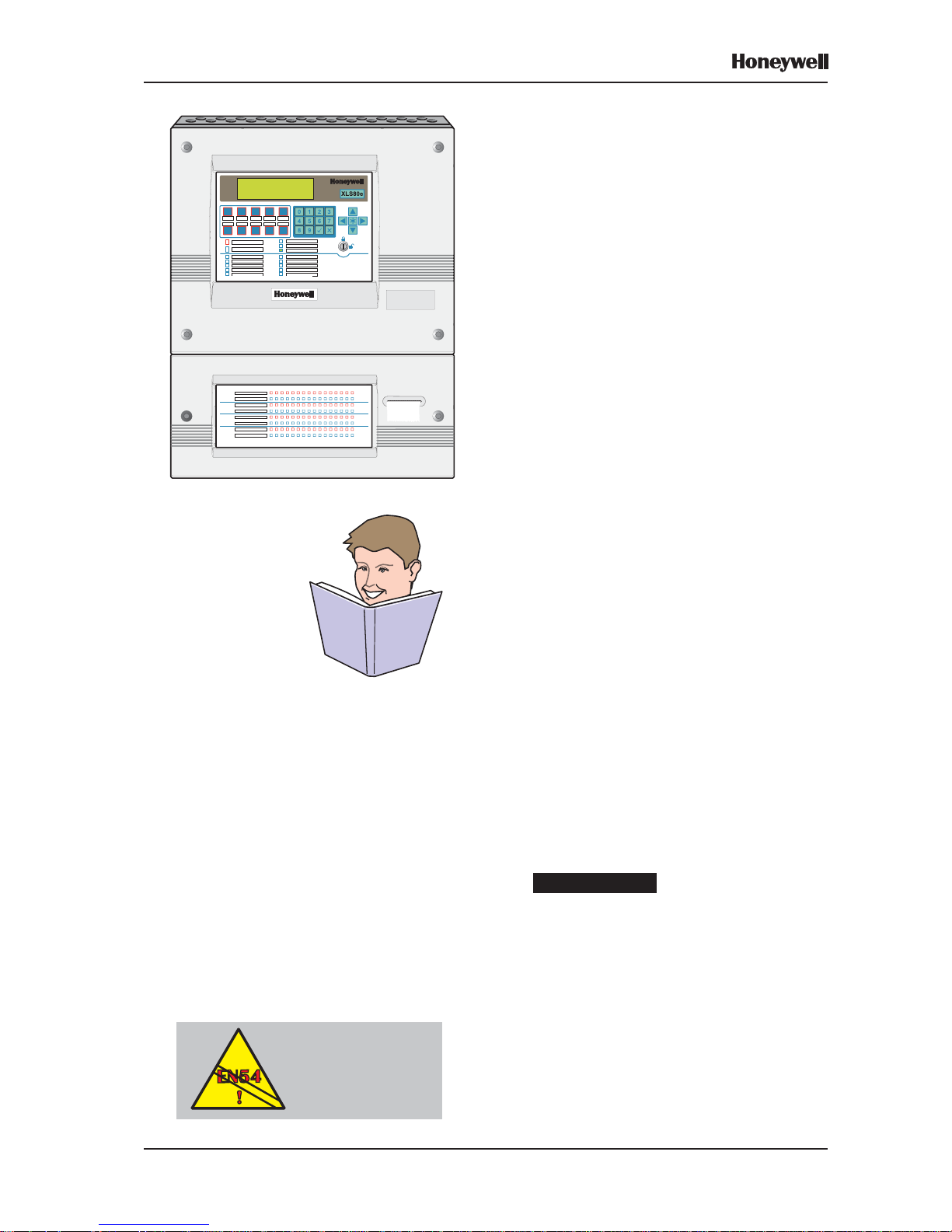
1.2 System Design and Planning
It is assumed that the system, of which the
XLS80e Series fire control equipment is a part,
has been designed by a competent fire alarm
system designer in accordance with the
requirements of EN54 Part 14, BS 5839 Part 1:
1988 and any other local codes of practice that
are applicable.
Be aware that....
This manual is not intended to be a fire
detection system design guide and should only
be used by (or under the supervision of) a
qualified system design engineer.
Some features of the XLS80e Series control
panel may , if used inappropriately , contravene
the requirements of EN54. Where there is a
possibility of such an occurrence, a suitable
warning is given with brief details of the EN54
requirement. A typical EN54 non-compliance
warning is illustrated at left.
EN54-2: 13.7
Maximum of 512
Sensors and/or MCPs
per panel unless
ELIBs are used
Page 9

2Honeywell, Issue 9
March 2007
XLS80e Fire Alarm Control Panels
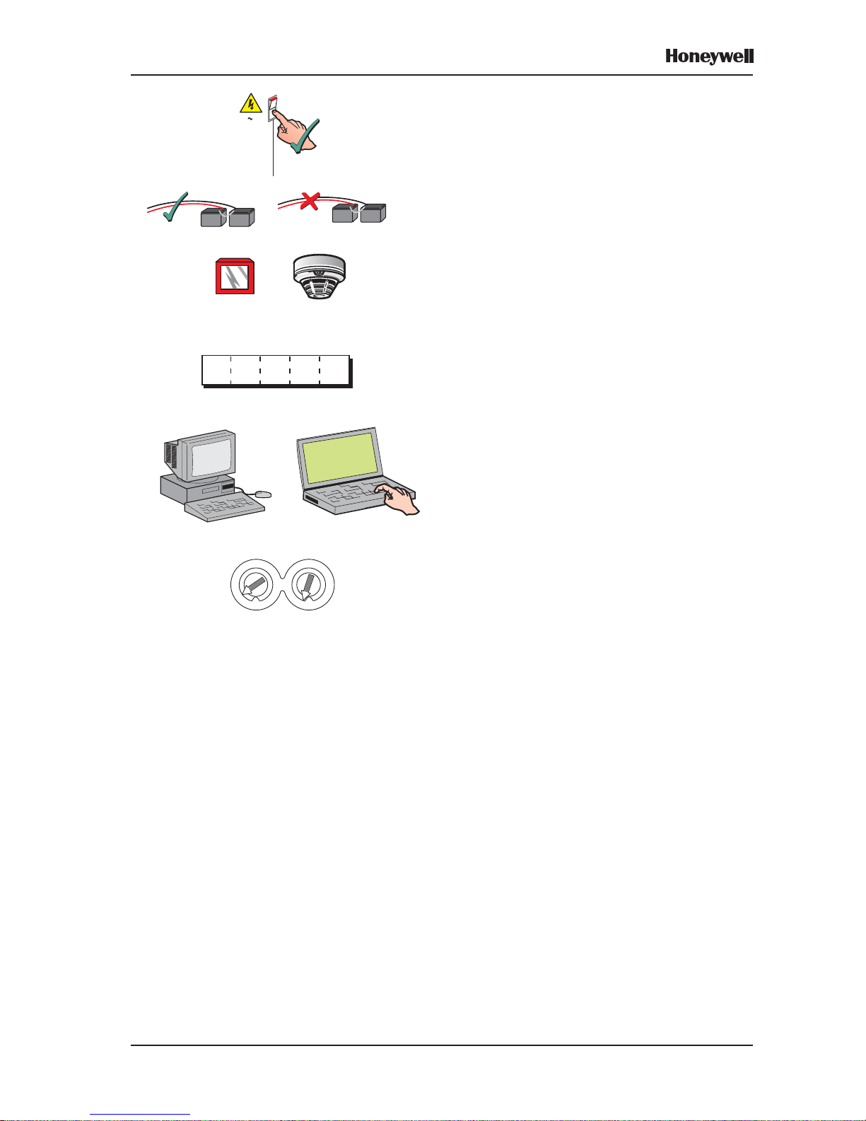
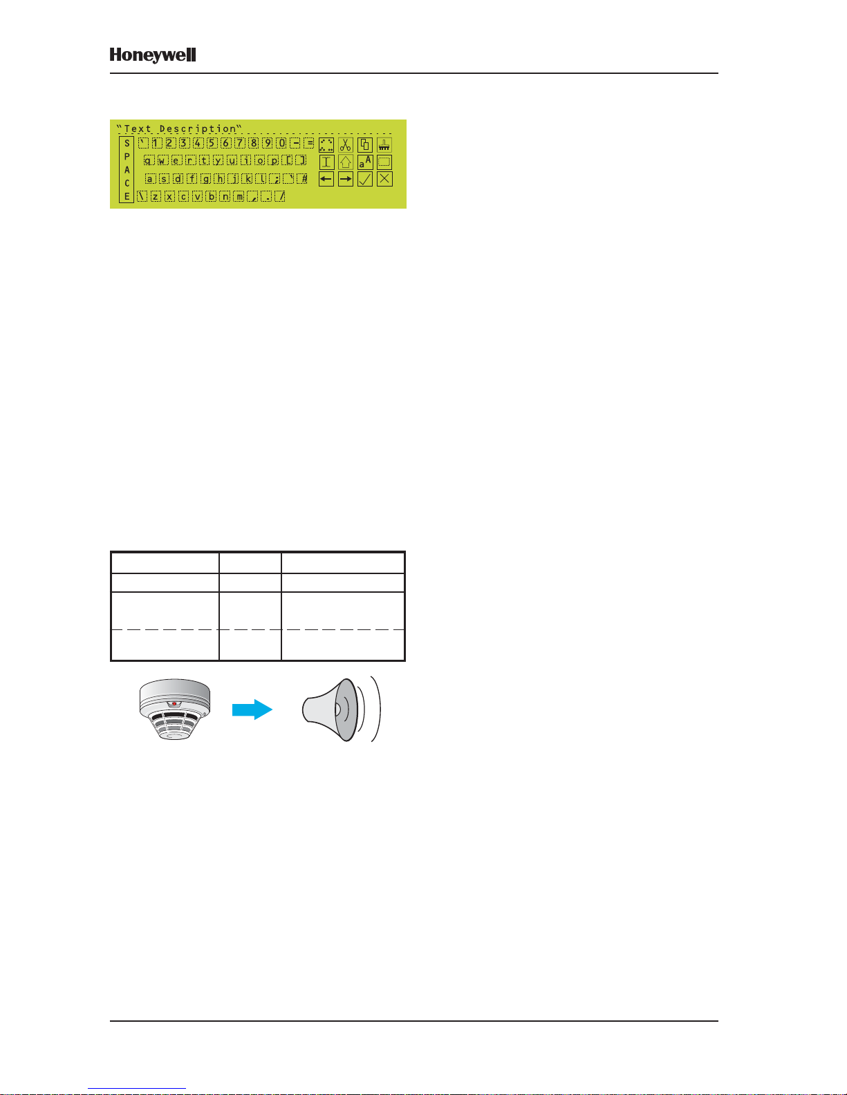
1.3 Glossary of Icons
Throughout this manual, and the other related
XLS80e Series manuals, a number of icons
are used in the illustrations to help clarify, or
simplify, p articular configuration procedures.
The following icons are used to advise or
indicate:
a. DO follow the recommended procedure or
method.
b. DO NOT use this procedure or method.
c. Inspection of an item or sub-assembly is
required at this point.
d. Following a defined process meets the
required approval/inspection criteria or
standards.
e. Following a defined process does not meet
the required approval/inspection criteria or
standards.
f. Additional items to be considered.
g. This icon placed next to a pushbutton
requires you to press it while configuring
the panel. Where two or more icons are
used, a number may be placed on or near
each hand to indicate the order of selection:
1 coming before 2.
h. Activity process step - flow arrow for single
action or iterative actions.
i. Leader arrow - used with activity processes.
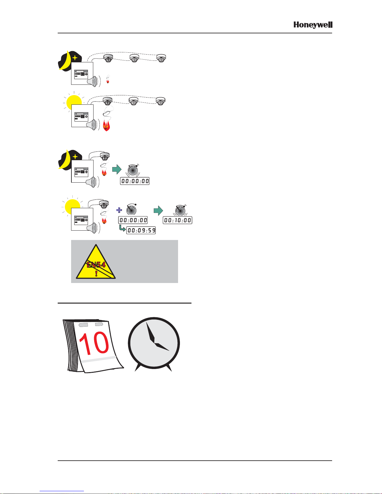
j. Sounder operating/Sounder not operating
or silenced.
k. Internal buzzer operating/not-operating or
silenced.
l. Digital clock timer - press and hold the
applicable pushbutton for the time indicated.
00:00:03
Page 10
3 Honeywell, Issue 9
March 2007
XLS80e Fire Alarm Control Panels
m. Mains power connected and switched ON.
n. Panel batteries power connected/
disconnected.
o. Manual Call Point (MCP)/Sensor.
p. Access 3A passcode entry requested to
continue with selected panel configuration
action (access 2 & 3 shown with three
asterisks).
q. IBM-compatible Personal Computer (PC)/
laptop.
r. Loop device address switch.
1
22
33
4455
66
77
81 8
0
09
9
230 V AC
50/60 Hz
Access 3A
*****
Page 11

4Honeywell, Issue 9
March 2007
XLS80e Fire Alarm Control Panels
1.4 Software Version Number
The XLS80e Series control panel software
version can be viewed by performing a lamp
test function.
Software version numbers are displayed for
the following:
a. The panel.
b. The Loop Interface PCB.
c. The Enhanced Loop Interface PCB.
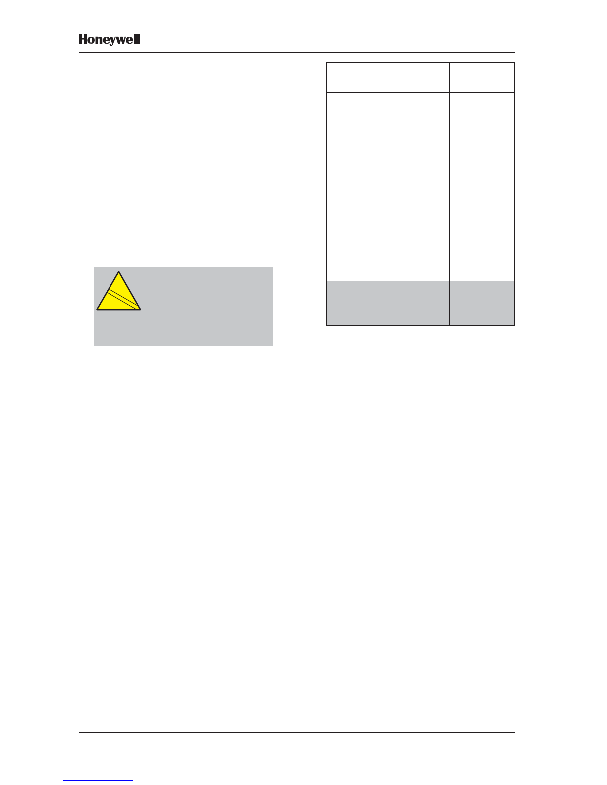
1.5 EN54 Functions
This fire control panel complies with the
requirements of EN54-2/4:1997. In addition to
the basic requirements of EN54-2, the panel
may be configured to conform with the
following optional functions - the applicable
clauses of EN54-2 are referenced as follows.
Options Clause
Indications:
Fault signals from points 8.3
Recording of the numbers of
entries into fire alarm condition 7.13
Controls:
Coincidence detection 7.12
Delay of the actioning of outputs 7.11
Disablement of each address
point 9.5
Test condition 10
Outputs:
Fire alarm devices 7.8
Fire alarm routing equipment 7.9
Fault warning routing equipment 8.9
Page 12

5 Honeywell, Issue 9
March 2007
XLS80e Fire Alarm Control Panels
The following features are provided by the
Power Supply Unit (PSU) of the XLS80e Series
Fire Control Panel Range to comply with
EN 54-4:
Feature of the XLS80e PSU EN 54-4
Clause
Derive power from the mains
supply 5.1
Derive power from a standby
battery source 5.2
Charge and monitor the standby
battery / batteries 5.3
Detect and signal various PSU
faults 5.4
1.6 Ancillary Functions
The following is a list of ancillary functions that
are provided by the XLS80e Series Fire Control
Panel Range in addition to those required by
EN54-2/4. These functions are described in
the section of this manual as referenced
(except the Sounder volt-free contact option,
which is described in the Installation and
Commissioning Manual):
Ancillary Function Manual
Section Refs.
Change sensitivity 5.1.2.7, 13
Control Matrix:
Output modes 7.4
Input type filtering 7.6.1.1
Output type filtering 7.6.2.2
Time-of-day filtering 7.6.2.2
Auto disable/enablement 7.7
Networking 14
Time-of-day functions -
disablements/configuration 3.11
Self-learn configuration 5.3.2
Module supervision options 5.1.1.4
Module silence options 5.1.4.7
Text editing 6
Sensor LED blinking mode 1 1 .1
Sounder pulsing periods 1 1. 4
Signal degraded monitoring
period 11.8
(continued)
Page 13
6Honeywell, Issue 9
March 2007
XLS80e Fire Alarm Control Panels
Ancillary Function Manual
Section Refs.
Loop start-up boost 1 1. 8
Calendar-based automatic
test selection 11.6
Automatic cancellation of
disablements 11.7
Mains Fail Fault
additional delay 1 1.13
RS232 Printer Output &
PC Interface 11.1
T emporary Configurations 1 1.1, 11.2
Volt-free cont act
output option 7.7
1
Extinguishing system 7.6.1.6
features 7.6.2.5
7.8, 1 1.20
1
Installation and Commissioning Manual
CAUTION:
This product is not compliant
with EN 12094-1.
EN
12094-1
!
EN
12094-1
!
Fire extinguishing installations in
Europe are required to be certified as
compliant to this standard.
Page 14
7
XLS80e Fire Alarm Control Panels
Honeywell, Issue 9
March 2007
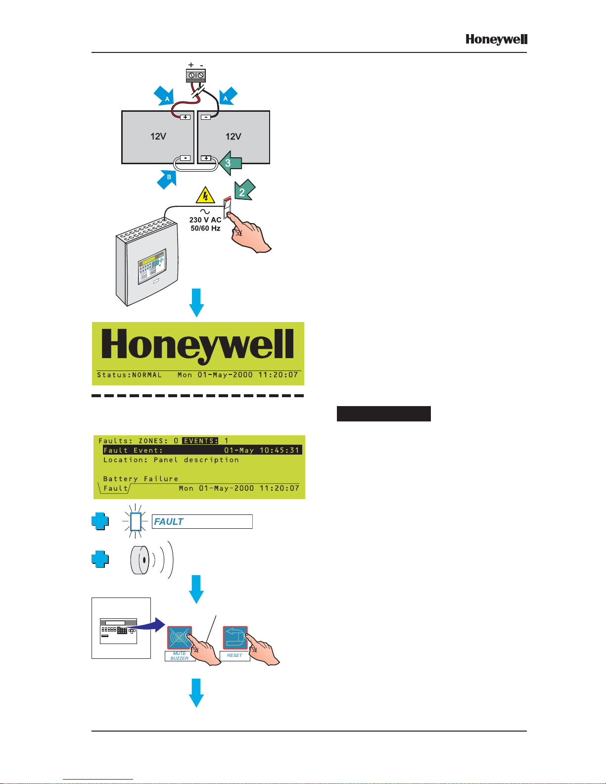
2 Power On/Start Up
To power up the system from a completely
powered-down condition:
1 Connect the two leads (A) from within the
panel to the two 12 V sealed lead-acid
batteries and then fit one end only of the
supplied interlink (B).
2 Connect and switch on the mains supply.
3 Connect the interlink to the remaining
terminal - but see item a. below.
After a few seconds the Status: NORMAL
display appears, indicating that the panel is
now ready to accept panel configuration
instructions. If the display is too dark to read,
adjust the contrast (see Section 3.3.2.1).
Be advised that....
a. If the battery connections are not completed
within 60 seconds of the mains supply
being switched on, the panel will indicate a
charger/battery fault. If this occurs:
1 Press the MUTE BUZZER pushbutton to
silence the buzzer (access level 1 or 2,
depending upon panel configuration).
2 After all necessary connections are
completed, press the RESET pushbutton
to clear the fault condition (access level 2).
IF BATTERIES ARE NOT CONNECTED WITHIN
60 SECONDS OF POWER-ON:
ALL FAULT INDICATIONS ARE CANCELLED
Page 15
8
XLS80e Fire Alarm Control Panels
Honeywell, Issue 9
March 2007
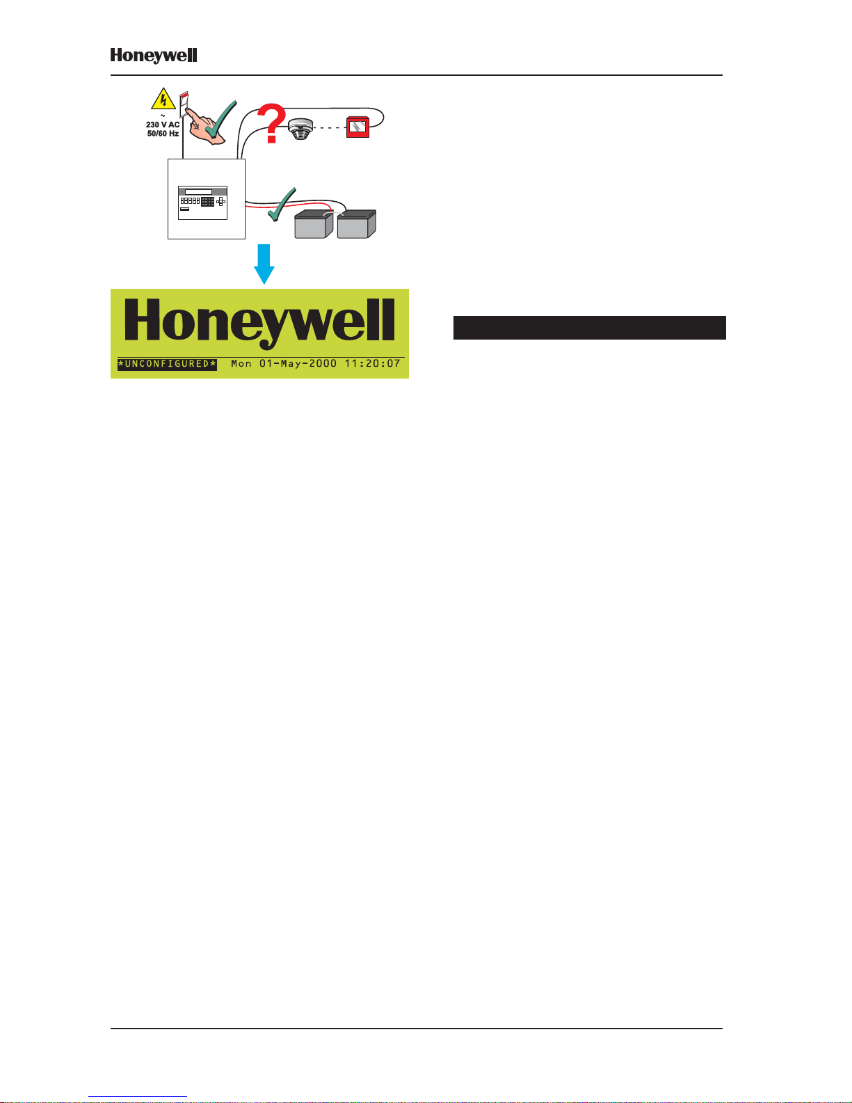
b. If the panel has not been configured with
any sensor or module data, i.e. the normal
system status at initial power up, the panel
displays ‘*UNCONFIGURED*’ unless it is
part of a network, in which case it displays
‘NORMAL’.
Powering up a network - special considerations
Master/Slave network
The following is recommended:
i When configuring a panel (either directly
or using the Offline Support Tool), first
disconnect the panel from the network.
When the COMMS FAIL message is
displayed (may take up to 2 minutes for a
Slave), press MUTE BUZZER to stop the
buzzer.
ii When all panels have been configured,
remove power from all of them. Connect
the Master panel to the network - set the
termination link on its RS485 PCB to the
‘ON’ (lower) position if it is not already so
configured (see Section 6 of the XLS80e
Series Installation and Commissioning
Manual).
iii Power-on just the Master panel. Wait until it
reports COMMS FAIL. Use MUTE BUZZER
to mute the buzzer. W ait one minute.
iv Connect and power-on each Slave panel
and Repeater in turn. There is no time
restriction on doing this. When all the
panels have been powered-on, wait one
minute, then press the RESET pushbutton
at the Master panel. The network should
stabilise (i.e. no error messages or buzzers).
v If the site arrangement does not require that
a termination link be set at the Master (see
Section 6 of the XLS80e Series Installation
and Commissioning Manual), fit the
termination links at the correct panels and
then set the link at the Master panel to the
‘OFF’ (upper) position. This can be done
with the system powered-on.
XLSNET peer-to-peer network
When all panels have been powered-up, allow
time for the network to settle. When no new fault
messages are being generated, press RESET .
Page 16
9
XLS80e Fire Alarm Control Panels
Honeywell, Issue 9
March 2007
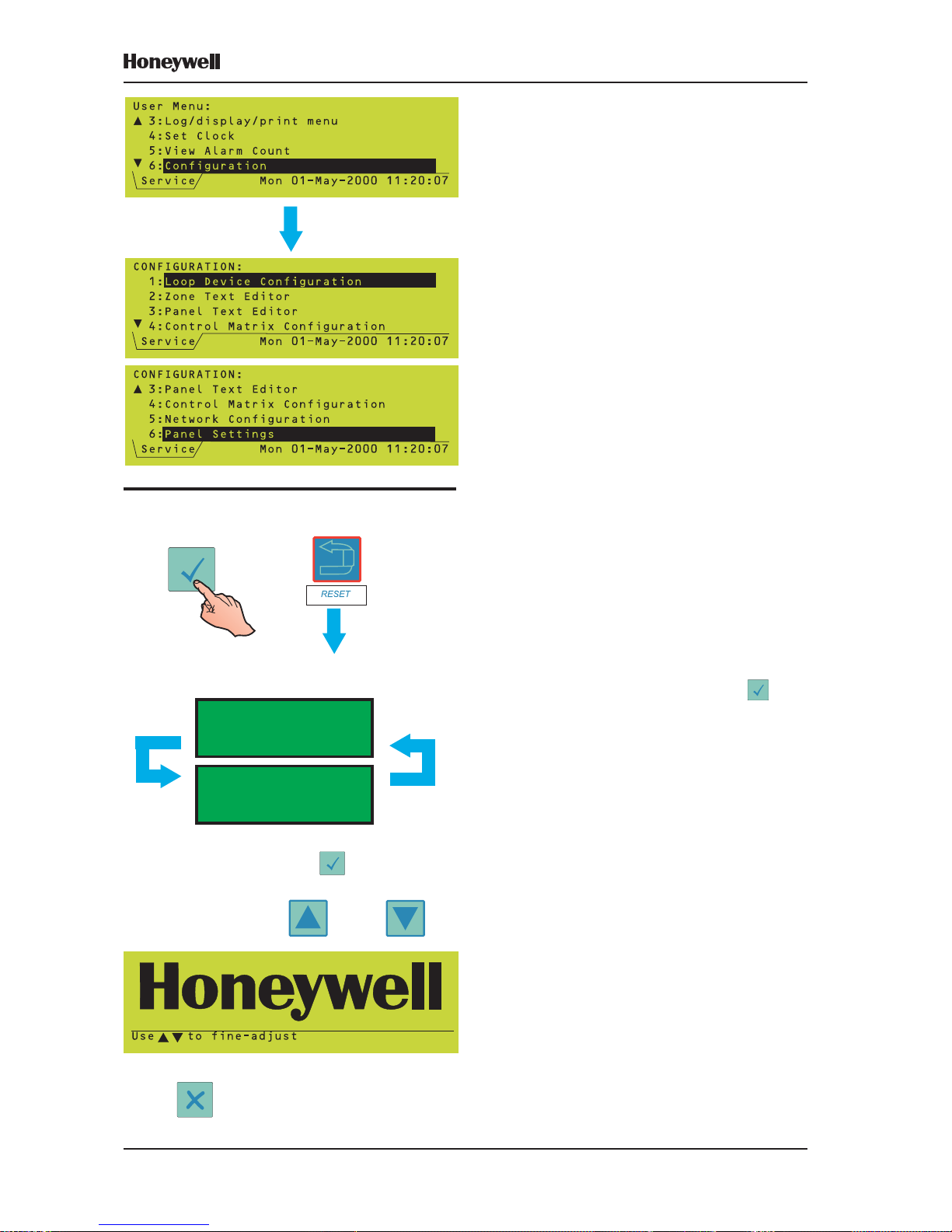
3 Panel Configuration Overview
This section gives a brief guide to the methods
for configuring the XLS80e Series panels.
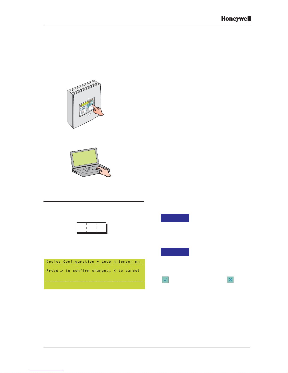
3.1 Where to Access the Configuration
Actions
The panel can be configured at one of the
following:
a. The panel, using its controls and indicators.
This is the slowest method, so the
manufacturer recommends that you only
use this method to perform small-scale
operational amendments after the panel is
fully commissioned. Refer to Section 3.3.
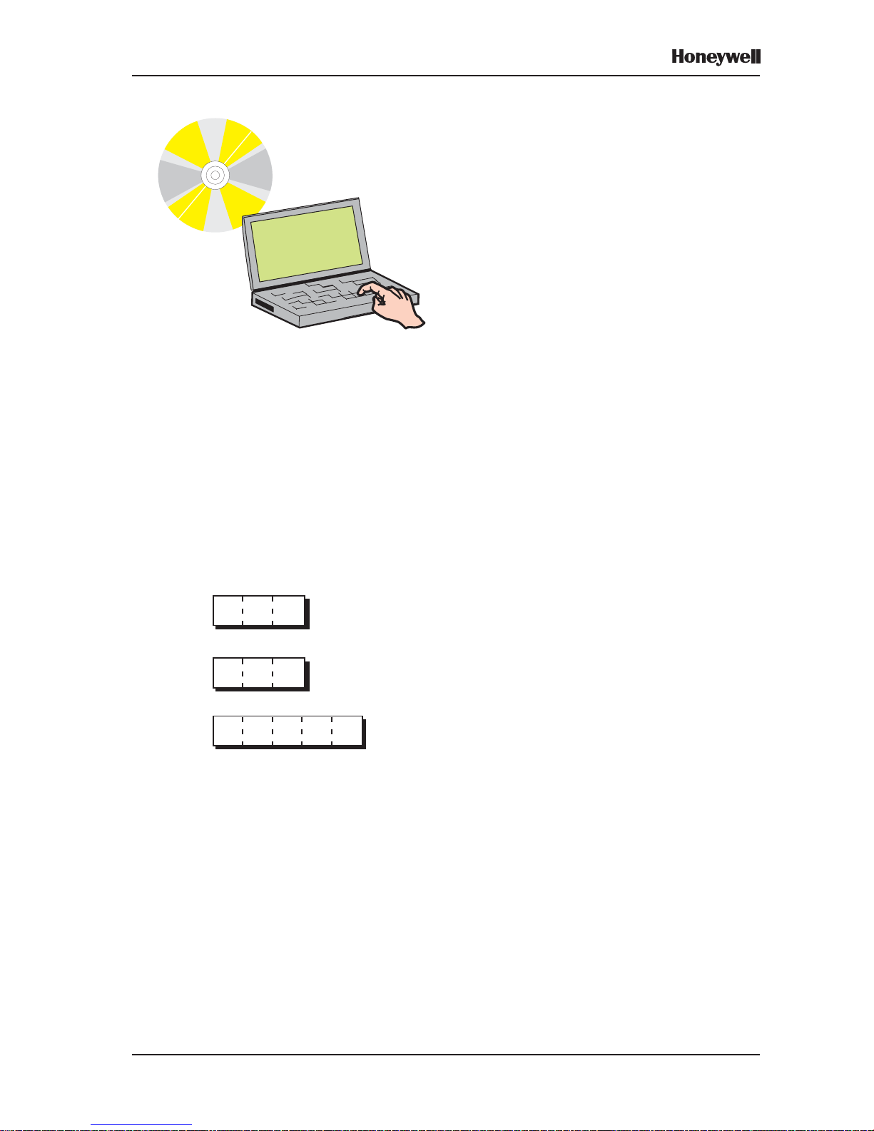
b. Off-line, using a Personal Computer (PC,
e.g. a laptop) running the Off-line Support
Tool. The updated configuration is
subsequently uploaded to the panel via its
internal RS232 port. Refer to Section 3.4.
At the start
The Access 3 passcode is required to configure
the panel. Refer to Section 3.5.
At the finish
A ‘Confirm Changes’ prompt is displayed. The
changes you have made are not permanently
stored in the panel’s memory unless you press
to select ‘confirm’. If you press to select
‘cancel’, the changes are lost.
OR
Access 3
***
Page 17

10
XLS80e Fire Alarm Control Panels
Honeywell, Issue 9
March 2007
3.2 Configuration Actions
The following configuration actions can be
performed:
a. An unconfigured panel can scan the loops
and learn what devices are installed, either
automatically or with manual user
intervention. Refer to Section 3.6.
b. Groups of devices on a configured panel can
be selected for deletion or change to a
different logical type. Refer to Section 3.7.
c. Individual devices can be added, removed
or changed manually. Refer to Section 3.8 .
d. The panel zone and device text descriptions
can be edited. Refer to Section 3.9.
e. The relationship between input devices (e.g.
sensors, manual call points) and output
devices (e.g. sounders) can be configured.
This is done in the Control Matrix, which is
a table of inputs, outputs and relationships.
Refer to Section 3.10.
g. The status of devices (e.g. the sensitivity)
can be set to vary depending upon the time
of day. Refer to Section 3.11.
h. The panel clock can be adjusted. Refer to
Section 3.12.
i. Various temporary and permanent
configuration options can be set. Refer to
Section 3.13.
j. The panel can be configured to be part of a
network. Refer to Section 3.14.
k. Sounders or remote fire outputs can be
delayed. Refer to Section 3.15.
l. Virtual input and output points can be
configured. Refer to Section 3.16.
LOOP DEVICE CONFIGURA TION - Sections 3.6-3.8
TEXT EDITING - Section 3.9
CONTROL MA TRIX - Section 3.10
TIME-OF-DA Y - Section 3.11
CLOCK SETTINGS - Section 3.12
P ANEL SETTINGS - Section 3.13
NETWORKING - Section 3.14
Z X C V B N M
Q W E R T Y U I O P
A S D F G H J K L
?
?
DELAYS - Section 3.15
Certain options on non-configuration menus
also require the access level 3 or 3A passcodes.
These options are described in Section 12.
VIRTUAL POINT CONFIGURA TION - Section 3.16
Page 18
11
XLS80e Fire Alarm Control Panels
Honeywell, Issue 9
March 2007
3.3 Using the Panel Controls and
Indicators
All of the configuration operations described in
this manual can be done using the panel
pushbuttons and Liquid Crystal Display (LCD),
with no external equipment required.
The panel remains ‘on watch’ during the
configuration sequence, and will therefore
respond appropriately to any fire or fault
conditions that arise.
The manufacturer recommends that you keep
a secure copy of the system configuration on a
PC as a backup, in case of difficulties in the
configuration sequence.
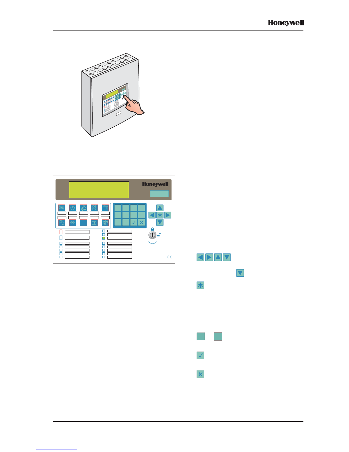
3.3.1 Pushbuttons
OPERA TING PUSHBUTTONS
CHANGE TABS - Scrolls through the tabbed
displays. Refer to Section 4.2 for further
information.
RESET - Restores normal operating status
when all alarm conditions have been removed.
Note: The other operating pushbuttons are not
used during configuration. Their
operation is described in the XLS80e
Series Operating Manual (997-474).
CURSOR AND NUMERIC PUSHBUTTONS
- Used to move around the LCD
menus. When the panel status is normal and if
the printer is fitted, advances the printer paper.
Used to: select menu options, select quick
methods of dis/enablement and walk test
cancellation, control the event log display , select
loop device parameters for edit, display existing
time-of-day programs, create a new Control
Matrix entry and select characters during text
editing.
0
to 9 - Used to select items and enter
data on the LCD.
- Used to accept an item or state on the
LCD.
- Used to cancel an item or state on the
LCD.
KEYSWITCH - Setting the keyswitch to the
right has the same effect as entering an
access 2 passcode. Set it to the centre to
deselect access 2.
XLS80e
0 1
2 3
4 5
6 7
8 9
ENDDELAY /
EVACUATE
MUTE
BUZZER
EXTEND
DELAY
SILENCE/
RESOUND
RESET
DAY
MODE
FIREO/P
DISABLE
CHANGE
TABS
ZONESIN
ALARM
PRE-ALARM
FIRE
FAULT
SYSTEM FAULT
SOUNDER FAULT/ DISABLED
FIRE O/PFAULT / DISABLED
FIRE O/PACTIVE
DAYMODE
DELAYSACTIVE
TECHNICALALARM
DISABLEMENT
TEST
POWER
EN54-2/41997
Page 19
12
XLS80e Fire Alarm Control Panels
Honeywell, Issue 9
March 2007
3.3.2 Liquid Crystal Display
The 6-line x 40 character display (using 240 x
64 pixels) provides a menu structure for the
operation and configuration of the panel. Most
of the operations described in this manual are
accessed from the Configuration Menu.
Further information about the display is given
in Section 4.
3.3.2.1 LCD Contrast Adjustment
This adjustment procedure as shown at left is
only available within the first two minutes after
power is applied to the panel.
To adjust the LCD contrast at other times,
select LAMP TEST (refer to the XLS80e Series
Operating Manual 997-474, Section 6.4 Lamp
Test) while at access level 3. Hold while
the test progresses. The contrast then cycles
and the remainder of the procedure is as shown
at left.
HOLD
THE DISPLA Y CYCLES BETWEEN MAXIMUM AND
MINIMUM CONTRAST :
MOMENT ARILY
WHEN THE REQUIRED CONTRAST IS PRESENT
ON THE DISPLAY, RELEASE .
TO FINE-ADJUST , USE:
WHEN COMPLETED, PRESS:
TO INVOKE THE SELECTED CONTRAST VALUE.
AND
AND PRESS
Page 20
13
XLS80e Fire Alarm Control Panels
Honeywell, Issue 9
March 2007
3.4 Using the Off-line Support T ool
This is a means of preparing the configuration
data, using an optionally-supplied software tool
which you can use without any connection to
the panel:
i. Save the prepared data to your PC hard disk.
ii. When the panel is ready to accept the
configuration data, simply connect it to your
PC, for the final data transfer to be made.
The XLS80e Off-line Support T ool is a complete
package for off-line configuration preparation. It
is supplied with all necessary panel configuration
instructions, consequently no further details are
given here.
This software package is available from
HONEYWELL or your supplier (Part Number:
020-558-100).
3.5 Passcodes
A passcode is required for all configuration
functions. You will be asked for the passcode
at the appropriate time (Sections 4.4.1 and 12.1
give examples). There are three access
passcodes:
Access 2 - Permits operation of the panel
pushbutton controls and provides access to
all menus except the Configuration menu.
It can be overridden by the panel keyswitch.
Note: Some menus have options which can
only be accessed using an Access 3 or
Access 3A passcode; these options are
described in Section 12.
Access 3 - Provides access to the
Configuration menu. Most operations
described in this manual require this
passcode.
Access 3A - Certain operations (changing
passcodes, and panel settings) require this
passcode.
Default passcodes are supplied with the panel.
These can be changed and the manufacturer
strongly recommends that you do so once
commissioning has been completed (see
Section 8 for default passcodes and the means
of changing the passcodes from these defaults).
Passcodes are not required for off-line
configuration using a PC, but they are required
when uploading or downloading configuration
data using this method.
Access 2
Access 3A
**
*****
*
Access 3
**
*
Page 21
14
XLS80e Fire Alarm Control Panels
Honeywell, Issue 9
March 2007
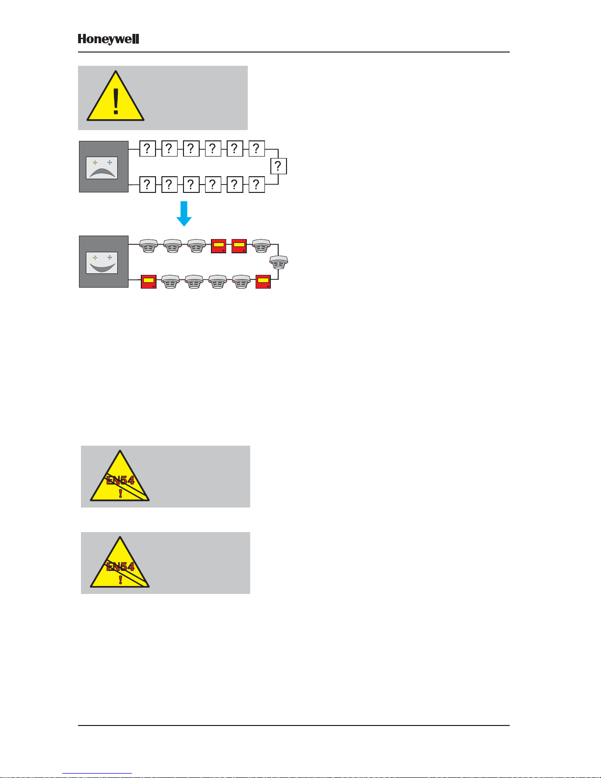
3.6 Learn Devices on Loops
The panel scans the loops and detects what
devices are fitted. This can be done on an
unconfigured panel. Section 5.3 describes how
to start, run and end a configuration learn.
There are two learn methods:
a. Auto-Learn. Loop device decisions are made
without the need for user intervention. Refer
to Section 5.3.2.
b. Manual Learn. Prompts the user each time
a new or changed device is detected. Refer
to Section 5.3.3.
Limitations on the Number of Devices
The XLS80e Series Control Panel design allows
for the connection of up to 198 loop devices per
analogue loop; i.e. up to 99 sensors and 99
modules. The maximum number of devices per
panel is:
a. 1584, if the Enhanced Loop Interface Board
(ELIB) is used for loops 3 to 8.
b. 512, if the Loop Interface Board (LIB) is used
for loops 3 to 8.
T o comply with EN54-2 in the event of a system
fault, a maximum of 512 sensors and/or MCPs
should be connected to the control panel across
those analogue loops that are not connected
to an ELIB. This number includes all
conventional zone detectors and/or MCPs
connected.
If the number of sensors and/or MCPs connected
to a loop exceeds 32, then isolators MUST be
used to segregate parts of the loop. This will
ensure that a short or open circuit will not cause
the loss of more than 32 sensors or MCPs. For
the XLS80e Series, do not place more than 25
loop devices between isolators (20 if FET
isolators are used).
There may be a further restriction, depending
on the types of sensor used, because of drive
limitations of the isolators. HONEYWELL
provide a PC-based tool to simplify loop loading
calculations. Contact the Te chnical Support
Department or your supplier for further
information.
EN54-2: 12.5.2
Maximum of 32 Sensors
and/or MCPs between
isolators
Before configuring
your panel, ensure all
loop devices are
installed
and each loop is
connected
EN54-2: 13.7
Maximum of 512
Sensors and/or
MCPs per panel unless
ELIBs are used
Page 22
15
XLS80e Fire Alarm Control Panels
Honeywell, Issue 9
March 2007
Limitations of the Auto-learn Method
If the auto-learn method is used on an
incomplete system it will give the false
impression that the system is fully operational.
In such cases, the auto-learnt data MUST be
checked carefully against the system
specification.
During the auto-learn procedure, input
module logical types are set to defaults.
Modules not conforming to the defaults must
be re-configured using the Manual Learn or
Configure Individual Device procedures.
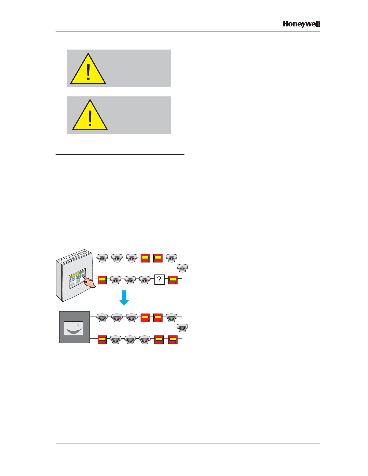
3.7 Configure Group of Devices
On a configured panel, this configuration
method allows a group of devices at consecutive
addresses to be deleted or all set to the same
type.
Refer to Section 5.2.
3.8 Configure Individual Device
This configuration method requires the user to
select each loop device and set all parameters
and conditions, e.g. sensitivity, time-of-day,
device text, etc. appropriate to it.
It can also be used to add further details to the
configuration resulting from the auto-learn
method.
Refer to Section 5.1.
Note: Sensitivity and alarm verification delay
recommendations are given in
Section 13.
Caution - a false indication
of a fully-functional system
is given if the Auto-learn
procedure is used on an
incomplete system.
Input module types are
set to defaults during the
Auto-learn procedure
and may require manual
re-configuration.
Page 23
16
XLS80e Fire Alarm Control Panels
Honeywell, Issue 9
March 2007
3.9 T ext Editing
There are three types of text that can be entered
and edited:
a. The panel or site name.
b. The zone description.
c. The device location text, which is shown on
the display when the system status is not
normal (i.e. alarm, test etc.). The device
description is also used at the printer, if
fitted.
The text is entered and edited from a text editor
which uses the LCD and the panel pushbuttons.
Refer to Section 6.
For panel and zone descriptions, the text editor
is invoked from dedicated menu options
(Sections 6.4 and 6.3 respectively). For device
location text it is invoked during the Configure
Devices on Loops procedure (Sections 5.1.2.3
and 5.1.4.3) or Virtual Point Configuration
procedure (Section 15).
3.10 Control Matrix
This very versatile system allows you to define
exactly which outputs (bells, etc.) are to be
activated depending upon which inputs
(sensors, etc.) have given a fire indication.
The capacity of the system is 512 matrix
entries.
Certain auxiliary functions may be specified
using the Control Matrix.
Refer to Section 7.
<Entry 1 input> activates: <Entry 1 output>
<Entry 2 input> activates: <Entry 2 output>
<Entry 3 input> activates: <Entry 3 output>
⇓ ⇓ ⇓ ⇓ ⇓ ⇓ ⇓ ⇓ ⇓ ⇓ ⇓ ⇓ ⇓ ⇓ ⇓ ⇓ ⇓ ⇓
<Entry 512 input> activates: <Entry 512 output>
CONTROL MA TRIX:
E.G.
Page 24
17
XLS80e Fire Alarm Control Panels
Honeywell, Issue 9
March 2007
3.11 Time-of-Day
This facility allows panel functions to be
modified depending upon the time of day . There
are three major applications:
a. Altering the sensitivity of sensors at certain
times of day - see Section 5.1.2.7.
b. Making some actions in the Control Matrix
(e.g. a delay) apply only at certain times of
day - see Section 7.6.2.2.
c. Cancelling all disablements on the panel at
certain times of day (not EN54-2 compliant)
- see Section 11.7.
Note: A Control Matrix entry can be used to
control disablement and enablement
functions, independent of the CANCEL
DISABLE function (see Section 7.7).
A typical Time-of-day program consists of one
or two daily periods specified by start and end
times, with an optional alternative for weekends.
Up to seven such programs can be in operation
in any one panel.
These programs run completely independently
of each other. Any particular sensor sensitivity ,
or Control Matrix entry , may be modified only
according to one of the programs.
Full details on Time-of-day program editing are
given in Section 9.
3.12 Setting the Clock
This facility allows:
a. The date and time to be adjusted.
b. The clock running speed to be adjusted.
c. The start and end dates of Summer Time to
be selected.
Refer to Section 10.
3.13 Panel Settings
For a number of panel functions, various options
are available e.g. Pulsing Sounder Modes,
Access Level for MUTE BUZZER etc, Relay
Circuits SILENCE Option. Some options are
temporary , most are permanent.
Refer to Section 11.
EN54-2: 9.1.2
Disablement and
re-enablement MUST be
a manual operation.
NIGHT - SET TO HIGH SENSITIVITY
DAY - SET T O LOW SENSITIVITY
NIGHT - CONTROL MA TRIX
HAS NO DELAY SET
DAY - CONTROL MA TRIX
HAS DELAY SET
Page 25
18
XLS80e Fire Alarm Control Panels
Honeywell, Issue 9
March 2007
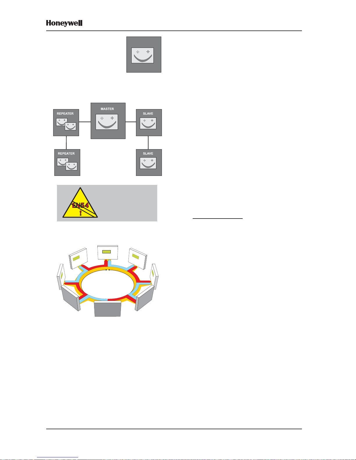
3.14 System Networking
The XLS80e Fire Control system is designed
so that control panels can work either as standalone units or networked with other panels.
When networked, each panel supervises its
own detection system of up to eight loops of
sensors and modules and functions
independently of all other panels.
A communication system enables events at
any panel to be relayed to other panels. This
causes appropriate annunciations and actions
at those panels.
Network Programming
The XLS80e Series panel can be used with one
of two networks:
a. Master/Slave network. Refer to Section 14
for further information.
b. XLSNET peer-to-peer fault-tolerant network.
Refer to Appendix 3 for further information.
Local Codes of Practice
Master/Slave network: The existence of network
communications is not, normally, intended to
replace the essential functions of the individual
panels (considered as isolated systems) but
to supplement and extend the facilities offered.
This means that each panel must be configured,
independently of the others, to comply with the
appropriate Code of Practice in force in the area
of the installation (i.e. in respect of the activation
of alarm devices in response to an Alarm of
Fire). This compliance must be maintained at
all times, even when communication with other
panels is suspended.
The Master/Slave
network does not
provide the transmission
path integrity required
by EN54-2: 12.5.3
OR
XLSNET PEER-TO-PEER NETWORK
XLS80e:
ST AND-ALONE
OR
MASTER/SLAVE NETWORK
RS485
Page 26

19
XLS80e Fire Alarm Control Panels
Honeywell, Issue 9
March 2007
3.15 Delays
Either the sounders or the fire alarm routing
equipment (remote fire outputs) which is used
to summon the fire brigade can be delayed:
a. To activate sounders immediately but delay
the remote fire outputs, use the Day/Night
Modes Configuration Option
(Section 11.19). The delay may be
extended to allow investigation. MCPs are
normally configured to override any delay.
b. T o delay sounders but activate the remote
fire outputs immediately, use the Control
Matrix to put an output delay on modules of
type BELL (Section 7.6.2.2). The delay
must then be enabled by the Operator (see
997-474, Operating Manual Section 7.5).
MCPs are normally configured to override
any delay .
3.16 Virtual Point Configuration
Up to 64 Virtual Input Points and up to 512
Virtual Output Points can be configured. They
are used with external systems (e.g. a Voice
Alarm panel) with which they communicate via
an RS232 port. They must be placed in a zone;
they then become possible inputs to or outputs
from the Control Matrix. Further information is
given in Section 15.
Page 27
20Honeywell, Issue 9
March 2007
XLS80e Fire Alarm Control Panels
4 The Display - Tabs, Events
and Menus
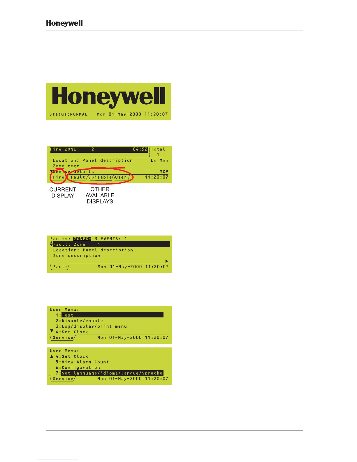
4.1 Introduction
4.1.1 Status: NORMAL
The Status: NORMAL display appears when:
a. No alarm or test conditions exist, and
b. No menus are being accessed.
4.1.2 Tabs
When conditions other than Status: NORMAL
exist, the LCD displays event data. More than
one type of data may be available for display
at any one time (eg, Fire Alarms, Fault s, Menus
etc.). When this occurs, the types of data
available are identified by tabs at the bottom
of the display .
4.1.3 Events
Fire Alarms, Pre-alarms, Faults, Disablement s,
Tests, Evacuate mode and Auxiliary input
activations are shown on Event displays. A
Fault event display is shown.
4.1.4 Menus
Menus displays are arranged in a heirarchy,
the top of which is a User Menu from which
other menus are accessed.
Page 28
21 Honeywell, Issue 9
March 2007
XLS80e Fire Alarm Control Panels
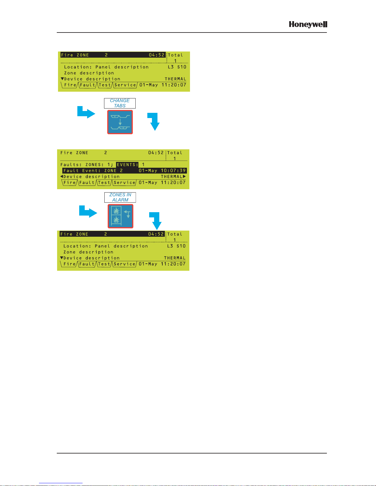
4.2 Tabs
When tabs are displayed, use the CHANGE
TABS key to scroll through the tabs and thus
display the corresponding data.
The tabs are (in descending order of priority):
EXTINGUISHING (if about to release;
otherwise priority is below FIRE)
FIRE
TECH. ALARM
PRE-ALARM
FAULT
DISABLE
TEST
EVACUATE
AUX
MAINT (access level 3 only unless Maintenance
Urgent)
USER (at access level 2) or
SERVICE (at access level 3)
The tabs are displayed in this order from left
to right. All the tabs display events except for
the USER and SERVICE tabs, which display
menus. The current tab is that without a line
above it.
Note: If there is insufficient room to display all
the tabs, the ones at the right (those with
the lowest priority) are omitted.
Use ZONES IN ALARM to go directly to the
FIRE tab without scrolling through the other
tabs. If there is more than one zone in alarm,
subsequent operations of the ZONES IN
ALARM pushbutton scroll through these
zones.
Note: If the FIRE tab is present but not
selected, and for 20 seconds none of
the panel pushbuttons are pressed, the
FIRE tab is then selected automatically .
Note: If the SERVICE or USER tab is selected,
and for 2 minutes none of the panel
pushbuttons are pressed, the tab is
deselected automatically and all
passcodes are cancelled (except the
access level 2 passcode when the
keyswitch is set to the horizontal
position).
Page 29
22Honeywell, Issue 9
March 2007
XLS80e Fire Alarm Control Panels
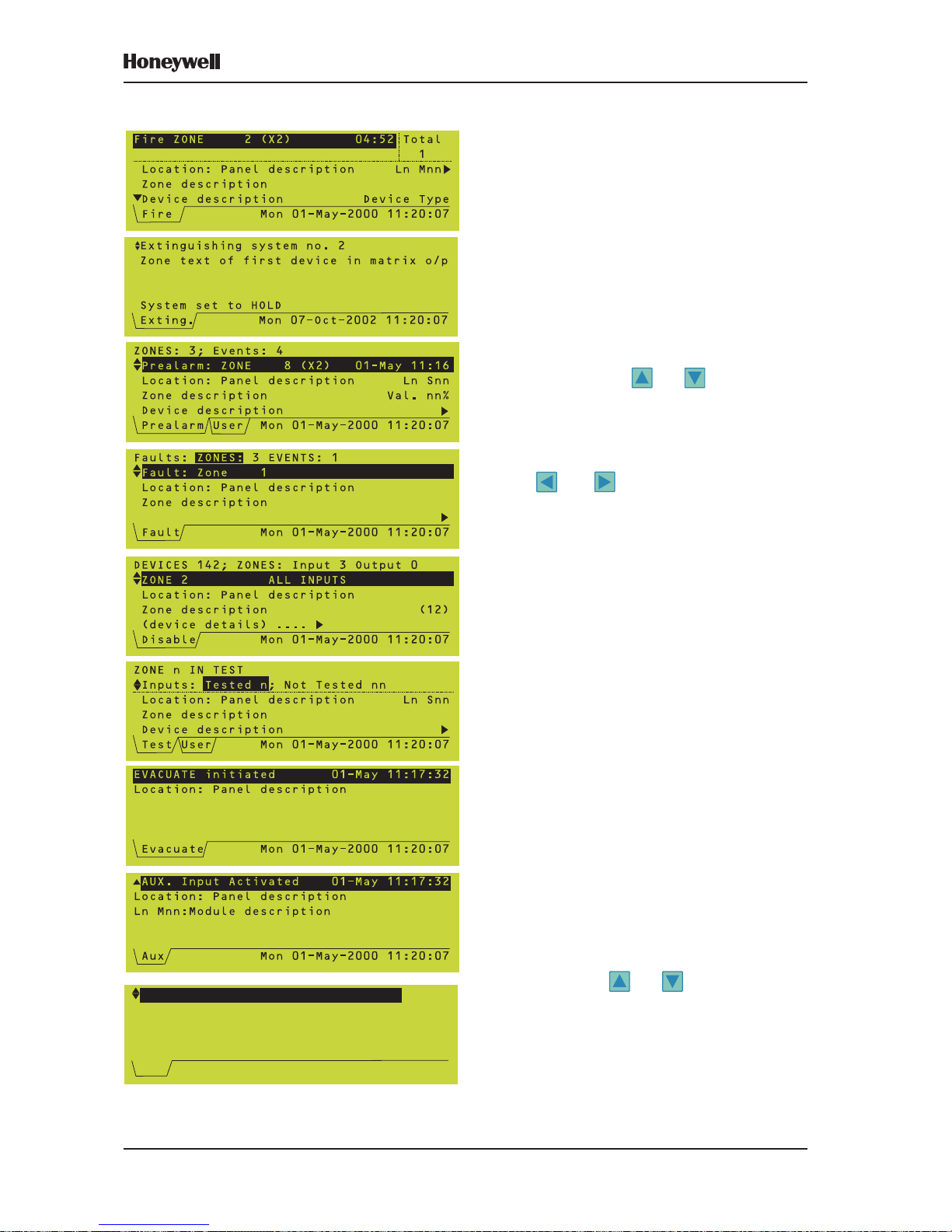
4.3 Event Displays
When a fire alarm, pre-alarm, fault,
disablement, walk test, evacuation, or auxiliary
input activation (if logging is configured)
occurs, an event display replaces the Status:
NORMAL display .
Note: FIRE, FAUL T , DISABLEMENT, or TEST
LEDs illuminate (also ZONE LEDs, if
fitted) as appropriate.
Example event displays are shown at the left.
In general, to move through the displays:
a. If more than one zone is affected by the
event, use the and arrows to scroll
through the zones. For FIRE events these
arrows scroll through device data; ZONES
IN ALARM scrolls through the zones.
b. If more than one device is affected, use the
and arrows to scroll through the
devices and device descriptions.
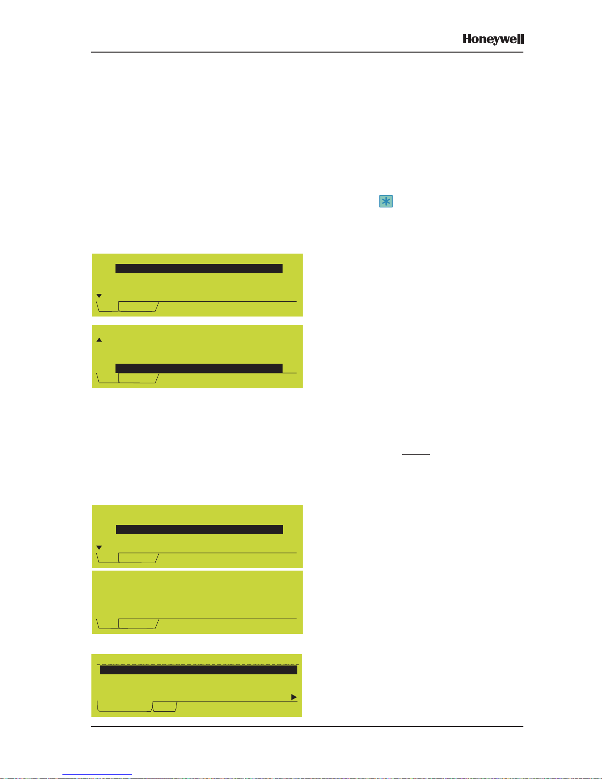
If a FIRE event occurs and the CHANGE T ABS
pushbutton is used to display other data, the
display area is reformatted so that the top two
lines continue to display fire information.
Further details about the event displays and
their operation are given in the XLS80e Series
Operating Manual, 997-474.
Aux T ab
At the end of the list of activated AUX inputs,
the AUX tab displays details of unconfigured
loop devices, should the panel find any during
polling. These are only shown on the panel
local to the devices. If multiple devices are
found, use the and pushbuttons to scroll
through the list of unconfigured devices (and
through the list of activated AUX inputs). In the
example, 1/3 means that ‘L3 S79’ is the first
of a total of three unconfigured devices found
(on all loops).
Note: Modules: the only types that may be
displayed are MON, CTRL and ZMX.
L3 S79 [OPT ] 1/3
Press * for user actions
Aux Tue 27-Jul-2004 11:20:07
Unconfigured Device found on loop
Page 30
23 Honeywell, Issue 9
March 2007
XLS80e Fire Alarm Control Panels
Tech.Alarm: ZONES: 1; Events: 2
Panel 13:Security Office L4 S05
Corridor 13
Ceiling Sensor GAS
Tech.Alarm User 27-Jul-2004 11:20:07
P13 ZONE 31 (x2) 27-Jul 11:20
By default, the panel does not scan for
unconfigured devices when the panel is
completely unconfigured (i.e. no sensors or
modules on any loop), however scanning can
be enabled by the user.
There is an optional, configurable upper limit
on the number of devices to be scanned. When
this number is reached, scanning can be
continued if extended by the user. The default
upper limit is 50 devices.
Press the pushbutton (level 3 access) to
display options to hide or show these devices
for access level 1 or 2 users, and to disable/
enable scanning for unconfigured devices.
a. If there are no devices left to show as a
result of HIDE, the AUX tab disappears
(assuming there are no AUX inputs active).
b. RE-SCAN causes the panel to clear all
indications of unconfigured devices, scan
the loops and then store the list of any
devices still unconfigured. This allows
devices that were present on the loop but
have since been removed to be identified.
The process takes up to about five minutes.
c. DISABLE clears the indicated devices from
the AUX tab and prevents the panel from
detecting further unconfigured devices. To
re-enable the scan, use the Log/Display/
Print menu as described in Section 12.4.
Note: Entry of access level 3 passcode for any
reason (except to display the above
menu from the AUX tab) always results
in SHOW ALL, unless the scan for
unconfigured devices has been
disabled. Any loop device configuration
operation always leads to a RE-SCAN.
If the configured upper limit is reached, the
option to extend the scanning is provided.
Note: The number of devices listed may be
slightly higher than the set limit (because
of synchronisation effects).
The DISABLE option resets the upper limit to
50 (this is the only method or reimposing a
limit if ‘0’, i.e. no limit has been selected).
T ech. Alarm tab
The T ech. Alarm tab is displayed when any Gas
Sensor Interface configured as Technical
Alarm is activated.
Unconfigured Devices Scan Menu
1:
2:HIDE All Unconfigured Devices
3:SHOW All Unconfigured Devices
4:RE-SCAN for Unconfigured Devices
Aux Service Tue 27-Jul-2004 11:20:07
HIDE This Device
Unconfigured Devices Scan Menu
2:HIDE All Unconfigured Devices
3:SHOW All Unconfigured Devices
4:RE-SCAN for Unconfigured Devices
5:
Aux Service Tue 27-Jul-2004 11:20:07
DISABLE Unconfigured Devices Scan
Unconfigured Devices Scan Menu
(50-devices limit reached)
1:
2:HIDE This Device
3:HIDE All Unconfigured Devices
Aux Service Tue 27-Jul-2004 11:20:07
EXTEND Unconfigured Devices limit
es Scan
Set limit to number of unconfigured
devices to be scanned for
(1-1584; 0=no limit): 50
Aux Service Tue 27-Jul-2004 11:20:07
Page 31

24Honeywell, Issue 9
March 2007
XLS80e Fire Alarm Control Panels
Maint Tab
This displays the maintenance status of any
MCS and Acclimate sensors installed on the
loops. If the panel is connected to an XLSnet
network and more than one panel contains
sensors requiring maintenance, an option to
choose the panel is provided.
There are four status messages:
a. Maintenance Urgent. Indicates drift limit
condition and is accompanied by a
SENSOR FAULT fault message.
b. Maintenance Alert. Indicates drift limit or
continuous IR saturation condition.
Maintenance Alert is also displayed in
respect of any Acclimate sensors.
c. 6 months to cell life expiration (MCS4 only).
d. IR light saturation condition (MCS4 only).
If a sensor returns from a maintenance
condition to its normal state, the display is as
shown opposite.
From the ‘Maint.’ tab, when the status of an
individual sensor is displayed, press the
pushbutton to display a Select Action menu
(the illustrations opposite cover all possible
options - in practice not all options may be
present, see below for details). The options are:
a. Actions on this sensors’s LEDs. The LED
can be set to OFF , 1-second pulsing, or ON
STEADY. This option is always available.
b. DELETE ALL restored sensors from log.
The maintenance status is stored in a log
(capacity 100 records per panel). This
option delete records from the log for all
sensors that are in the ‘Restored from
Maintenance Condition’ state. Available
provided at least one sensor is in this state.
Note: Use the Historic & Data Log Tool
(supplied with the Windows Support
Tool) to access the log.
c. DELETE this sensor from log. Available
only if the current sensor is in the ‘Restored
from Maintenance Condition’ state.
d. DISABLE THIS DEVICE. Always available,
may be ENABLE THIS DEVICE depending
upon disablement status of current sensor.
e. PRINT Sensors in Maint. condition. Always
available.
f. Select another Panel. Displays the Select
Panel option. Only available if the panel is
connected to an XLSnet and more than one
panel contains sensors requiring maintenance.
Select Panel: ( digit )
Panel 1: North-West Building
Panel 2: South Building
Fault Maint. Service 20-Oct 10:15:33
*Panel 3: Secret Laboratory
Recorded on 20-Oct-06 10:05
L1 SO2:upper corridor
Zone 10 MCS4 value 15%
Press * for user actions
Fault Maint. Service 20-Oct 10:15:33
Maintenance Urgent
Recorded on 20-Oct-06 10:05
L1 SO2:upper corridor
Zone 10 MCS4 value 40%
Fault Maint. Service 20-Oct 10:15:33
Restored from Maintenance Condition
L1 S02 Select Action:
1:
2:DELETE ALL restored sensors from log
3:DELETE this sensor from log
4:DISABLE this device
Fault Maint. Service 20-Oct 10:15:33
Actions on this sensor's LEDs
L1 S02 Select Action:
3:DELETE this sensor from log
4:DISABLE this device
5:PRINT Sensors in Maint. Condition
6:
Fault Maint. Service 20-Oct 10:15:33
Select another Panel
Page 32

25 Honeywell, Issue 9
March 2007
XLS80e Fire Alarm Control Panels
4.4 Menu Displays
4.4.1 To Display the User Menu
To display the User Menu when the system
status is Normal, enter the passcode. To use
the Configuration menu and to use some
options on the other menus an access 3 or 3A
passcode must be entered (refer to Section 8
for further details about passcodes).
Note: If event tabs are displayed, CHANGE
TABS first displays these sequentially,
then when the last of these has been
displayed the passcode prompt is
displayed.
Note: An access 2 passcode is also provided,
for use by the operator. If this is entered
the tab is named USER instead of
SERVICE. You can enter the access 3
or 3A passcode at either a prompt for
an access 2 passcode or at a prompt
for an access 3 passcode.
Note: If no further pushbuttons are pressed
the Status: NORMAL display is redisplayed after 2 minutes.
Only the first four options of the User Menu
are displayed at this time. The selected option
is highlighted. Use the and pushbuttons
to scroll through the other options.
Use the pushbutton to return to the S tatus:
NORMAL display .
ACCESS 3 or 3A
PASSCODE,
THEN
(REPEATEDLY)
OR
OR TIMEOUT
Page 33

26Honeywell, Issue 9
March 2007
XLS80e Fire Alarm Control Panels
6
4.4.2 To Navigate Through the Menus
In this example it is desired to display the
Configuration Menu, which is option 6 on the
User Menu.
With the User Menu displayed, press 6 to
go to the Configuration Menu directly .
Alternatively, highlight option 6 on the User
Menu and then select the option as shown
below.
If there are more than 9 items in the menu,
the numeric key highlights a suggested option
but does not select it. 1 alternates between
‘1’ and 10’.
Press the key to exit from the menu.
(REPEATEDLY
UNTIL CURSOR IS
BESIDE OPTION 6)
OR
OR
OR
Page 34

27 Honeywell, Issue 9
March 2007
XLS80e Fire Alarm Control Panels
4.4.3 Menu Structure
Note: ** Requires access 3 passcode. The
menu primarily used in this manual is
the Configuration Menu, therefore its
sub-menus are shown in greater detail
than is the case for the other menus.
*** Requires access 3A passcode.
+Only available if a PRN-ID printer is
configured.
^Only available if at least one SMART
sensor is configured on the loops.
STATUS: NORMAL
DISABLE/ENABLE
INDIVIDUAL DEVICE
ALARM OUTPUTS
BY ZONE
LOG/DISPLAY/
PRINT MENU
LOG/DISPLAY
DEVICE DATA
PRINT DEVICE
DATA
SET CLOCK
DISPLAY/PRINT
EVENT LOG
USER MENU
ALARM INPUTS
BY ZONE
TEST
ZONE WALK TEST
CONTROL OUTPUT/
SOUNDER TEST **
DAILY/WEEKLY AUTO
TEST NOW
LAMP TEST
PRINTER
CONTROL +
VIEW ALARM
COUNT
DISPLAY BAD
POLL LOG ***
A
DISPLAY ACTIVE
C. MATRIX RULES **
UNCONFIGURED
DEVICES **
MCS SENSORS
COMMISSIONING ^
Page 35

28Honeywell, Issue 9
March 2007
XLS80e Fire Alarm Control Panels
Note: If access level 2 is entered by use of the keyswitch, no decision has been
made by the user to enter a specific access level passcode. In this case
the ‘CONFIGURATION’ menu option is replaced by ‘ENTER LEVEL 3
PASSCODE’. When a level 3 passcode is entered, the User Menu is redisplayed so that the level 3 user can select any of the menus available at
access level 2 (to access their level 3 options, see Section 12), in addition
to the ‘CONFIGURA TION’ menu.
SET LANGUAGE
CONFIGURE
INDIVIDUAL DEVICE
AMEND DEVICE
CONFIGURATION
MANUALLY
CONFIGURATION **
LOOP DEVICE
CONFIGURATION
ZONE TEXT EDITOR
CONTROL MATRIX
CONFIGURATION
PANEL TEXT EDITOR
PANEL SETTINGS ***
A
CONFIGURE GROUP
OF DEVICES
LEARN DEVICES
ON LOOPS
REVIEW/EDIT
CONTROL MATRIX
PRINT CONTROL
MATRIX
NETWORK
CONFIGURATION
MASTER/SLAVE
CONFIGURATION
XLSnet NETWORK
CONFIGURATION
STAND ALONE
CONFIGURATION
REPEATERS ONLY
CONFIGURATION
PRINT NETWORK
CONFIGURATION
PASSCODE
CHANGE
INTERNAL BUZZER
OPTIONS
SENSOR/MODULE
LEDs
PULSING SOUNDER
MODES
AUTOMATIC TEST
OPTIONS
LOOP OPTIONS
ACCESS LEVEL FOR
MUTE BUZZER
RELAY CIRCUITS
'SILENCE' OPTION
LCD BACKLIGHT 'ON'
DURATION
ISOLATED RS232
PORT SETUP
REMOTE FIRE
OUTPUT OPTIONS
EXTINGUISHING SYS
COMMON OPTIONS
NUMBER OF LOOPS
ON PANEL
WALK TEST
OPTIONS
DISABLEMENT
OPTIONS
PANEL FUNCTIONS
UNLATCHED NONALARM I/P LOGGING
MAINS/PSU FAULT
DELAYS
BLANK LINES IN
PRINTED EVENTS
DIAGNOSTIC RS232
PORT SETUP
DAY/NIGHT MODES
CONFIGURATION
ALARM
COINCIDENCE
VIRTUAL OUTPUT
POINT
VIRTUAL POINT
CONFIGURATION
VIRTUAL INPUT
POINT
EXTINGUISHING SYS
COMMON OPTIONS
NETWORK
SETTINGS
THERMAL ALARM
VERIFICATION TIME
Page 36

29
XLS80e Fire Alarm Control Panels
Honeywell, Issue 9
March 2007
5 Loop Device Configuration
You can configure loop devices:
a. Individually (Section 5.1).
b. As a group (Section 5.2).
c. As a system (Section 5.3), learning the
loops either automatically or with manual
intervention.
5.1 Configure Individual Device
5.1.1 Select a Device
1 From the Loop Device Configuration menu,
select the Configure Individual Device
option.
2 Select the number of the loop to which the
device is physically wired (‘n’ is the highest
loop number on the panel, e.g. 4, 6 or 8).
3 Select whether the device is a sensor or
module (both have device numbers in the
range 1-99, so this selection determines the
meaning of the device number).
NUMERIC KEYS,
THEN
SEE NEXT PAGE
Page 37

30
XLS80e Fire Alarm Control Panels
Honeywell, Issue 9
March 2007
4 In this example SENSOR was chosen. The
procedure for choosing a MODULE is the
same. Enter the device number. Leading
zeros are optional.
In this example the device is an optical sensor
(type OPT); all other values use ‘n’ to represent
a numeric value and ‘a’ or a description to
represent alphabetic characters.
The and pushbuttons step through the
parameters that can be edited for the currentlydisplayed device. Press the pushbutton to
edit the currently-highlighted parameter. The
following sections describe the options
available for each parameter for a sensor, and
then the differences applicable to a control
module.
Note: The and pushbuttons step
through the various devices on the
system (all loops).
If the device has not been configured, the
display is as shown.
FROM PREVIOUS P AGE
NUMERIC KEYS,
THEN
REPEATED
USE OF
FURTHER
USE OF
Page 38

31
XLS80e Fire Alarm Control Panels
Honeywell, Issue 9
March 2007
5.1.2 Change Device Configuration Sensors
The following can be altered for sensors:
a. The device type.
b. The zone or cell in which the device is
placed.
c. The device location text. Note that the zone
text is displayed but cannot be edited here
(it is edited in the Zone Text Editor, see
Section 6.3).
d. Sensitivity levels (see Section 13 for
recommendations).
e. Verification delay times. See Section 13 for
recommendations.
f. Priority option.
g. Time-of-day sensitivity changes.
5.1.2.1 Edit Device Type
Select the required TYPE. If no sensor exists
at the entered number, its type is NONE.
Available types are:
Type Description Physical Type
NONE Deleted - no sensor
exists at this address
HEAT Thermal sensor TC808
ION IONisation sensor TC807
OPT Photo sensor TC806
MULT Photo/Thermal sensor TC840
LASR Photo ‘Laser’ sensor TC846
GAS Gas Sensor Interface
MCS4 Optical/thermal/infra-red/
carbon monoxide
If you change a device type, the other settings
(except zone, cell and device text) revert to
default.
Gas Sensor Interface
Interface IIG1 requires three consecutive
sensor addresses; the lowest is shown as type
GAS and the other two as NONE. Interface IIG4
requires up to twelve consecutive addresses
(depending upon how many of four possible
interfaces are configured at the device), the first,
fourth, seventh and tenth are type GAS and the
others NONE. The following then applies:
i Attempts to change the type at the
addresses shown as ‘NONE’ display the
message ‘This address is not available:
GAS sensor occupying one of the previous
two addresses.’.
ii Type GAS cannot be configured at an
address if either or both of the next two
addresses are already occupied (the
message ‘PLEASE DELETE next two
higher-addressed sensors before installing
GAS sensor at this address.’ is displayed).
TO
MAKE
SELECTION
GAS SENSOR INTERFACE:
This device produces a Technical
Alarm by default, but can be
configured as a Fire Alarm by the
configuration option shown below. The Control
Matrix groups Technical Alarms with Fire Alarms.
Device Configuration - Loop 3 Sensor 8
Type GAS Zone 203 Cell 0
Zone <Storage area >
Loc. <First IIG4 >
=select *=edit =next device =finish
TECHNICAL ALARM device:
Device Configuration - Loop 3 Sensor 8
1:Normal Alarm Input
2:TECHNICAL ALARM device
Set device type - Loop n Sensor nn
6:OPTICAL 'LASER' SENSOR (TC846)
7:GAS Sensor Inteface (IIG1/IIG4)
8: (MCS4)
4:PHOTO (OPT) SENSOR (TC806)
5:PHOTO/THERMAL (MULT) SENSOR (TC840)
Multi Criteria 4 Sensor
Page 39

32
XLS80e Fire Alarm Control Panels
Honeywell, Issue 9
March 2007
5.1.2.2 Edit Device Zone or Cell
Zone Number
Enter the zone number within the displayed
range. RANGE! is displayed if the entered
number is out of range. For details of zone
ranges, refer to Section 14.1.2. The ‘Internal
Zone no.’ is only displayed if network zones
are used, also in this case an error message
is displayed if you try to configure more than
255 zones on a panel.
Reference Number
If network zones are used, a maximum of 99
devices can be placed in the zone. Each device
is identified by a reference number in the range
1 to 99 (i.e. maximum of 99 devices in a zone).
When a device’s zone number is configured
the device is automatically given the first
available reference number by default.
To change this default, either enter one of the
unused reference numbers from the display,
or a reference number that is already used by
a device. If the latter is chosen, the option to
swap the number for that device with one of
the unused numbers is provided automatically
(see below). If the swap is not accepted then
the entered number is rejected.
Cell Number
Devices can optionally be placed in a cell in
addition to a zone. Certain Control Matrix
functions can be set to apply to the cell rather
than the zone.
Enter the cell number in the range 1 to 255, or
select 0 if the device is not to be placed in a
cell.
NUMERIC
KEYS, THEN
NUMERIC
KEYS, THEN
Page 40

33
XLS80e Fire Alarm Control Panels
Honeywell, Issue 9
March 2007
5.1.2.3 Edit Device Location Text
Edit the text description which is used for the
various tab displays (e.g. fire, fault) and for
printing at the printer. Section 6 describes how
to use the text editor.
5.1.2.4 Edit Sensitivity level and Fault
Supervision
The alarm and pre-alarm sensitivities can be
configured.
The Gas Sensor Interface Alarm, Pre-alarm
and Fault levels are all editable values in the
range 4 to 20mA instead of pre-set levels.
Details are given in Section 5.1.3.3.
Alarm
The illustration shows the alarm sensitivity
selected for edit. Up to 9 pre-set levels are
available for each sensor (except
Photo/Thermal (MULT) and MCS); for all
sensor types (except MULT and MCS) the
default setting is L5. L1 is most sensitive and
L9 is least sensitive. Refer to Section 13 for
recommendations.
Details of MULTI sensor sensitivity are given
in Section 5.1.3.
Further information about MCS sensors
sensitivity is given in Section 5.1.3.2.
ALARM
Page 41

34
XLS80e Fire Alarm Control Panels
Honeywell, Issue 9
March 2007
Pre-alarm
Again the default setting is 5 for all types of
sensor except Photo/Thermal (MULT) and
MCS. The alarm and pre-alarm ranges do not
overlap, except for MUL T and MCS for which
the alarm must be set lower than the pre-alarm
for pre-alarm supervision to work (set it equal
or higher if pre-alarm supervision is not
required). For other sensor types the pre-alarm
sensitivity range includes ‘0’ which selects no
pre-alarm supervision.
Note: The ALARM and PRE-ALARM values
are upper thresholds, i.e. an alarm
occurs if the sensor reading equals or
exceeds the threshold.
The option to Lock the Pre-alarm level is then
provided:
a. If NO (default) is chosen and Time-of-Day
is used to vary the alarm sensitivity
(Section 5.1.2.7), Pre-alarm sensitivity
changes with Time-of-Day by the same
amount that is set for Alarm. Also, for MUL TI/
MCS sensors, Pre-alarm is ignored at those
times when Thermal-only mode L6 is in
operation for Alarms as a result of a Control
Matrix rule or Time-of-Day.
b. If YES is chosen, the Pre-alarm sensitivity
remains fixed at the selected level. Also,
for MULTI/MCS sensors, Pre-alarm is no
longer ignored at those times when
Thermal-only mode is in operation for
Alarms. A ‘#’ symbol is displayed beside the
Pre-alarm value.
Fault
To comply with EN54-2: 8.3, fault supervision
is always set to ON.
Device Configuration - Loop 1 Sensor 30
LOCK Pre-alarm level against Time-of-Day
Variation etc.:
1
2:YES
:NO
PRE-ALARM
Page 42

35
XLS80e Fire Alarm Control Panels
Honeywell, Issue 9
March 2007
5.1.2.5 Edit Verification Delay
Set the verification delay within the displayed
range. RANGE! is displayed if the entered
number is out of range. Refer to Section 13
for recommended verification delays.
Alarm verification display is shown on the left.
The Fault verification display has the same
layout.
5.1.2.6 Edit Priority Option
Set the priority polling ON of OFF. When ON
the device will scan at intervals of less than
one second.
A maximum of 43 devices per loop may be
designated as priority; however, to obtain the
1-second scan interval do not designate more
than 21 devices per loop as priority (as more
devices are assigned priority scan status, the
scan rate becomes slower for the remaining
devices).
5.1.2.7 Time of Day
The sensitivity can be varied at different times
of day .
Refer to Section 9 for details of time-of-day
programming.
Note: If the device’s alarm sensitivity is
changed, the time of day variation is
cancelled automatically to prevent it
going out of range.
NUMERIC
KEYS, THEN
Page 43

36
XLS80e Fire Alarm Control Panels
Honeywell, Issue 9
March 2007
5.1.2.8 LED Blink Options
Select whether the device’s LEDs follow the
panel setting (Section 11.2) or are set to blink
or not (non-blink).
5.1.2.9 LED Also Controls
Select the required option:
a. NONE. There are no additional controls.
b. SOUNDER. For use with B601BH base
with integral sounder; the sounder will be
silenced by operation of the panel’s
SILENCE/RESOUND (to silence) or
RESET pushbuttons.
c. Non-Sil. Control. Used when auxiliary
equipment is driven in parallel with the
sensor LED. Control of this auxiliary
equipment is then independent of the
SILENCE/RESOUND pushbutton - it is only
switched off by operating the RESET
pushbutton.
5.1.2.10 End the Editing Session
When all the changes have been made, press
to confirm them. The panel then uses the
changed parameters.
THEN
Device Configuration - Loop n Sensor nn
Type OPT Zone nn Cell n
Zone <(no zone text defined) >
Loc. <Device text description >
LED BLINK MODE
=select *=edit =next device =finish
Follow Panel Setting
Device Configuration - Loop n Sensor nn
LED BLINK MODE
1:
2:Always BLINK
3:Always NON-BLINK
Follow Panel Setting
Device Configuration - Loop 1 Sensor 1
Type OPT Zone 20 Cell 0
Zone <Corridor >
Loc. <Ceiling >
LED also controls:
=select *=edit =next device =finish
NONE
Device Configuration - Loop 1 Sensor 1
LED also controls:
1:
2:SOUNDER
3:Non-Sil.CONTROL
NONE
Page 44

37
XLS80e Fire Alarm Control Panels
Honeywell, Issue 9
March 2007
5.1.3 MULTI, MCS & GAS Sensor
Interface Sensitivities
5.1.3.1 Photo/Thermal (MULT) Sensors
Device type MULT applies to the
TC840ME.
ACCLIMATE, has a Thermal-Only mode, i.e.
a mode in which the sensor does not respond
to smoke.
Sensitivity (including Acclimate)
When configuring the Alarm and Pre-alarm
sensitivity for MULT sensors, there are five
sensitivity levels plus Pre-alarm disable (L0) and
(for Acclimate only) the Thermal-Only mode:
Sensitivity MULT Sensor
Levels Default Settings
L1 (Most)
L2 For Pre-alarm Threshold
L3
L4
L5 (Least) For Alarm Threshold
L6 Thermal-Only mode (Acclimate)
For Pre-alarm to operate, the Pre-alarm
Threshold MUST be set at least one level
below the Alarm Threshold. In Thermal-Only
mode (L6), Pre-alarm applies to both smoke
and heat, unless L6 is linked to Time-of-Day
or Day Mode with Lock Pre-alarm monitoring
not set, in which case there is NO Pre-alarm
in L6 mode.
Thermal Mode by Zone (Acclimate only)
All Acclimate sensors in a zone or range of
zones and configured as described below can
be set to their Thermal-Only mode by the
Control Matrix. To configure an Acclimate
sensor for this action, set its device
configuration option ‘Thermal Mode by Zone’
to ‘Yes’. Only those Acclimate sensors so
configured will be included in the Control Matrix
output. The default for this option is ‘No’.
ILLUSTRATION SHOWS ACCLIMA TE CONFIGURED
IN THERMAL-ONLY MODE FOR ALARM.
NORMALLY ACCLIMATE WILL BE CONFIGURED
AT L5 FOR ALARM, AND THE THERMAL-ONLY MODE
WILL BE INVOKED VIA A TIME-OF-DAY PROGRAM
OR VIA THE DAY MODE PUSHBUTTON. SEE
SECTION 9.4.
THERMAL MODE BY ZONE OPTION IS ONLY
DISPLA YED FOR MULTI SENSORS AND IS ONLY
APPLICABLE FOR ACCLIMATE DEVICES. AN
ACCLIMATE SENSOR SET TO ‘YES’ WILL BE
INCLUDED IN ANY CONTROL MATRIX ENTRY
FOR WHICH THE INPUT IS NON-FIRE OR TRUE
AND THE OUTPUT ‘SET TO THERMAL-ONLY
MODE’ INCLUDES THE SENSOR’S ZONE
NUMBER. SEE SECTION 7.6.2.6.
Software version 4.33 and above:
Default Alarm thr eshold is L5 for
newly installed multi-criteria sensors
(was L3 on previous versions; if
software is upgraded to 4.33, existing
devices retain this default).
Pre-Alarm threshold value MUST
be LOWER than the Alarm
threshold value to be effective.
Device Configuration - Loop n Sensor nn
Alarm Sensitivity level (1-6):
(1 = most sensitive, 5 = least)
(6 = Thermal-only mode; default = 5)
6
Page 45

38
XLS80e Fire Alarm Control Panels
Honeywell, Issue 9
March 2007
5.1.3.2 MCS Sensors
The system supports Multi-criteria (MCS)
sensors.
The MCS4 sensor has the capability for carbon
monoxide, photoelectronic (optical), infra-red
and thermal detection.
This sensor has a thermal-only mode as
described on the previous page for Acclimate.
The Alarm and Pre-alarm levels and defaults are
as described for Acclimate, and the verification
delays are the same as for a MUL TI sensor .
5.1.3.3 GAS Sensor Interface
The analogue level output from the Gas
Sensor Interface IIG1 or IIG4 is a current in
the range 4 to 20mA. The Alarm, Pre-alarm
and Fault thresholds are editable within this
range. Use the and pushbuttons to toggle
between the Pre-alarm and Fault parameters.
The thresholds are selected for editing in the
same manner as for other devices, but the edit
procedure is different:
1 Enter the new value in tenths of milliamps.
All digits must be entered including the one
after the decimal point, even if it is zero.
2 The decimal point is not displayed during
the entry. It is redisplayed when the
pushbutton is pressed.
See the example at left, in which the Alarm
Sensitivity is changed from 12.0mA to 13.5mA.
Device Configuration - Loop 3 Sensor 5
Alarm Sensitivity level (4-20mA):
(Please type in units of 0.1mA):
12.0
Device Configuration - Loop 3 Sensor 5
Alarm Sensitivity level (4-20mA):
(Please type in units of 0.1mA):
135
Device Configuration - Loop 3 Sensor 5
Alarm Sensitivity level (4-20mA):
(Please type in units of 0.1mA):
13.5 Confirm ( /X)?
Device Configuration - Loop 3 Sensor 8
Type GAS Zone 203 Cell 0
Zone <Storage area >
Loc. <First IIG4 >
Sensitivity: Alarm=12.0mA Pre= mA
=select *=edit =next device =finish
10.0
Device Configuration - Loop 3 Sensor 8
Type GAS Zone 203 Cell 0
Zone <Storage area >
Loc. <First IIG4 >
Sensitivity: Alarm=12.0mA Fault= mA
=select *=edit =next device =finish
4.0
Page 46

39
XLS80e Fire Alarm Control Panels
Honeywell, Issue 9
March 2007
5.1.4 Change Device Configuration Modules
The following can be altered for modules:
a. The device type.
b. The zone or cell in which the device is
placed.
c. The device location text. Note that the zone
text is displayed but cannot be edited here
(it is edited in the Zone Text Editor, see
Section 6.3).
d. Module supervision options (see
Section 13 for recommendations).
e. Verification delay times. See Section 13 for
recommendations.
f. Priority options.
g. Silence and Pulse options.
5.1.4.1 Edit Device Type
Select the required TYPE. If no module exists
at the entered number, its type is NONE.
Available types are:
Type Description Physical Type
NONE Deleted - no module
exists at this address
MCP Manual Call Point MMX
BELL Bell/sounder circuit or
loop-powered sounder CMX
CTRL (generalised)
Control Function CMX
MON (generalised)
MONitoring function MMX
SPRK Sprinkler Monitor ASPR Aspirator Interface AUX. Auxiliary Module
ZMX Low cost version of CDI ZMX
CDI Conventional
Detector Interface CDI
LBM Loop Booster Module LBM
Note: While sensor types are Physical device
types (they are determined by the
sensor hardware and must be selected
so as to match the actual sensor
installed at that address), module types
are Logical device types. These refer
to one of the physical module types as
shown in the table above.
TO
MAKE
SELECTION
Set device type - Loop n Module nn
1:
2:MCP MANUAL CALL POINT
3:BELL/SOUNDER
4:CONTROL MODULE
5:MONITOR MODULE
DELETE
Set device type - Loop n Module nn
6:SPRINKLER MODULE
7:ASPIRATOR INTERFACE
8:AUX INPUT
9:ZMX ZONE MONITOR
10:CDI ZONE MONITOR
Set device type - Loop n Module nn
7:ASPIRATOR INTERFACE
8:AUX INPUT
9:ZMX ZONE MONITOR
10:CDI ZONE MONITOR
11:LBM LOOP BOOSTER MODULE
Page 47

40
XLS80e Fire Alarm Control Panels
Honeywell, Issue 9
March 2007
Auxiliary Modules
Any Input (MMX) module can be defined as
logical type AUXILIAR Y.
T o make use of several special Control Matrix
facilities, certain input modules must be
defined as logical type AUXILIARY. Auxiliary
modules:
a. Cannot generate an ALARM of FIRE,
b. Are not included in Zone operations,
c. Must be referred to individually (not by
zone) in Control Matrix records,
d. Generate non-latching Control Matrix
output operation,
e. Are treated in the usual way, if faulty,
f. Cannot have a delayed output.
It is essential that the correct type of
Module is used.
Loop Boosters
Only the following parameters can be
edited:zone, cell and (network zones)
reference numbers, location text, short-circuit
supervision option (default ON), fault
verification delay, priority polling and LED blink
mode. The following cannot be edited: alarm
supervision option (always OFF), open-circuit
supervision option (always ON) and alarm
verification delay.
5.1.4.2 Edit Device Zone or Cell
The procedure for modules is identical to that
described for sensors (Section 5.1.2.2).
5.1.4.3 Edit Device Location Text
The procedure for modules is identical to that
described for sensors (Section 5.1.2.3).
5.1.4.4 Edit Module Supervision Options
The alarm, short-circuit and open-circuit
supervision options can be configured. They
are the means of enabling or disabling
supervision of FIRE alarms, short-circuit faults
and open-circuit faults and relate to the
monitored load. They indicate that standard
termination supervision is checked (ON) or
ignored (OFF) respectively. See Section 13
for recommendations.
The ZMX module supervision options are
configured as for the CDI and other modules
and should be left at their default setting.
Page 48

41
XLS80e Fire Alarm Control Panels
Honeywell, Issue 9
March 2007
Alarm Supervision
Set the alarm supervision ON or OFF.
Note: It is not possible to set Manual Call
Points (device type MCP) ALARM
threshold to OFF.
Short- and Open-Circuit Supervision
The method of selection is the same as shown
for Alarm Supervision.
For CDI and ZMX the S/C supervision option
is not supported. It is set to OFF and cannot
be changed (a short-circuit in the supervised
zone is detected as a fault of open-circuit).
Note: Control Modules CMX used as outputs
and with the ‘tabs’ snapped of f, and the
10-way Control Modules, must have the
O/C sensitivity set to OFF, otherwise
they will remain in an open circuit fault
condition.
5.1.4.5 Edit Verification Delay
Edit module verification delays in the same
manner as described for sensors (see
Section 5.1.2.5). See Section 13 for
recommendations. The ranges for modules
are different from those for sensors.
5.1.4.6 Edit Priority Option
Edit priority polling in the same manner as
described for sensors (see Section 5.1.2.6).
If CDI or ZMX modules are used to connect
conventional MCPs: to meet the response time
specified in BS5839 Part 1 para. 20.2(b), set
these modules to priority and do not exceed
21 priority devices per loop.
5.1.4.7 Backup Alarm
The default is ‘Normal Alarm Input’. Alarm
Supervision must be set to ON for the
options on this menu to take effect.
‘Backup Alarm monitor’ applies only to MON
modules on XLSNET . Only set this if the device
is intended to relay alarm status from a
neighbouring panel to provided backup if the
XLSNET fails. The option ensures that alarms
are treated correctly by the panel. Do not
include the device in zone-specific or devicespecific Control Matrix rules.
MAKE
SELECTION
Device Configuration - Loop n Module nn
1:
2:Backup Alarm Monitor
Normal Alarm Input
Page 49

42
XLS80e Fire Alarm Control Panels
Honeywell, Issue 9
March 2007
5.1.4.8 Bell and CTRL Module Options
Additional options (SILENCEABLE and
NORMAL PULSE) are displayed for CMX
modules of types BELL and CTRL.
Module SILENCE Options
This option determines whether a Control
Output is switched off when the SILENCE/
RESOUND pushbutton is operated to silence
the sounders.
Module PULSE Options
This option also applies to inputs derived from
an AUX input module. It determines whether
this module, if activated in pulsing mode, will
pulse at the standard (default) rate (1 sec ON,
1 sec OFF) or at a slower, user-defined rate
and pulse length. This rate and pulse length
are defined in the configuration options (see
Section 11.4, Pulsing Sounder Modes).
Note: If the loop is heavily loaded with devices
(especially sounders), select SLOW
PULSE to ensure adequate
synchronisation of sounders.
Note: Only one user-defined rate may be set for
the system in addition to the standard rate.
5.1.4.9 AUX Module Options
AUX modules can be individually selected as
logged or not logged. The former is
recommended for fire-critical equipment, while
the latter is overridden if the ‘Unlatched nonalarm input logging’ option is set to ‘logged’
(see Section 11.11, which also gives further
information about these settings).
5.1.4.10 ASPR/MCP/MON/SPRK Options
Select the effect of an open circuit - FAULT
gives a fault indication, INDICA TION displays
‘OPEN-CIRCUIT’ on the AUX tab.
5.1.4.11 LED Blink Options
See Section 5.1.2.8.
5.1.4.12 End the Editing Session
The procedure for modules is identical to that
described for sensors (Section 5.1.2.9).
Page 50

43
XLS80e Fire Alarm Control Panels
Honeywell, Issue 9
March 2007
5.2 Configure Group of Devices
This option allows a group of devices to be
deleted or all set to the same type. The devices
must be at consecutive addresses on the same
loop and in the same zone, and if being deleted
they must be of the same type.
This example shows the procedure for
sensors. The procedure for modules is
identical. Y ou cannot mix sensors and modules
in this procedure.
To start this option:
1 From the Loop Device Configuration menu,
select the Configure Group of Devices
option.
2 Select the loop in which the devices are
fitted.
3 Select either sensor or module.
4 Select the address range by entering the
first address and then the last address. In
this example, 10 is entered as the first
address, it therefore becomes the lowest
address in the range that can be entered
for the last address.
Note: GAS sensors require at least three
consecutive sensor addresses. If the
selected range has an IIG-1 or IIG-4
device at one of the next two addresses
below the range the message ‘This
address is not available: GAS sensor
occupying one of the previous two
addresses.’ is displayed. It is not
possible to configure a group of GAS
sensors using the Configure Group of
Devices option.
NUMERIC KEYS,
THEN
MAKE
SELECTION
NUMERIC KEYS,
THEN
SEE NEXT PAGE
NUMERIC KEYS,
THEN
Page 51

44
XLS80e Fire Alarm Control Panels
Honeywell, Issue 9
March 2007
5 Select either DELETE or select the device
type to which the group of devices is to be
set. Sensor types are defined in
Section 5.1.2.1 and module types are
defined in Section 5.1.4.1.
6 Either:
a. Press to confirm the deletion, or
b. If a device type is chosen, select the zone
into which the devices are to be placed.
7 When all the changes have been made,
press to confirm them. The panel then
uses the changed parameters.
FROM PREVIOUS P AGE
EITHER (IF DELETE)
OR (IF ANY SELECTION EXCEPT DELETE)
IF NOT DELETE, USE
NUMERIC KEYS. THEN IN
EITHER CASE
PANEL USES THE
CHANGED DEVICE
CONFIGURATION
Page 52

45
XLS80e Fire Alarm Control Panels
Honeywell, Issue 9
March 2007
5.3 Learn Devices on Loops
This option allows the panel to detect and
automatically configure devices that it finds
already connected to the loops. If the panel
has already been configured, the panel can
amend the details of any installed devices that
do not match the configuration.
By default, all sensors on all loops are learnt,
then all modules on all loops. Smaller ranges
can be selected.
The procedure can be run automatically , or in
manual mode (the system pauses on each new
learnt device).
5.3.1 Starting the Procedure
To start this option:
1 From the Loop Device Configuration menu,
select the Learn Devices on Loops option.
2 Select the loop from which the learn
process is to begin. If you want to learn the
entire system, this should be set to ‘1’.
3 If you want to learn all the devices on the
loop selected in step 2, select SENSOR,
otherwise the panel will begin learning from
the module addresses on the loop.
4 Select the start address. To learn all the
addresses, set this value to ‘1’.
SEE NEXT PAGE
NUMERIC KEYS,
THEN
NUMERIC KEYS,
THEN
Caution - a false indication
of a fully-functional system
is given if the Auto-learn
procedure is used on an
incomplete system.
Input module types are
set to defaults during the
Auto-learn procedure
and may require manual
re-configuration.
Using the defaults through-
out will select the entire
system.
Page 53

46
XLS80e Fire Alarm Control Panels
Honeywell, Issue 9
March 2007
5 Select the loop at which the learn process
is to end (‘n’ represents the highest loop
on the system).
6 If you want to learn all the devices on the
loop selected in step 5, select MODULE,
otherwise the panel will stop learning from
the sensor address selected in step 7.
Note: If the loop number selected in step 2 is
the same as that selected in step 5, and
the type of device selected in step 3 is
the same as that selected in step 6, then
only that type of device (i.e. SENSORS
or MODULES) will be learnt.
7 Select the address of the last device to be
learnt.
Note: If the end address is lower than the start
address, the learn process occurs in the
opposite direction to normal. If the start
and end addresses are the same (for a
single type of device on a single loop),
only one device is learnt.
8 Two options are then available:
a. Pause learning only if in error. This is
AUTO-LEARN. Refer to Section 5.3.2.
b. Pause on each new/changed device. This
is MANUAL LEARN. Refer to Section 5.3.3.
FROM PREVIOUS P AGE
NUMERIC KEYS,
THEN
NUMERIC KEYS,
THEN
Page 54

47
XLS80e Fire Alarm Control Panels
Honeywell, Issue 9
March 2007
5.3.2 Run in Auto-Learn Mode
If you select this option, then:
Note: Steps 1 to 3 are omitted if only sensors
were selected in the procedure of
Section 5.3.1. The choices made in these
steps are only used for new or changed
modules, not for unchanged modules that
have already been configured.
1 Select whether MULTI devices of type
Acclimate are automatically configured for
Thermal Mode by Zone operation
(Section 5.1.3) or not. The ‘Thermal Mode
by Zone’ option in the device configuration
menu is then set automatically to ‘Y es’.
2 Select a logical device type with which any
MMX modules found during the learn
procedure will be configured.
3 Select a logical device type with which any
CMX modules found during the learn
procedure will be configured.
4 Select the action to be taken if an
unterminated module (or one with broken
tabs) is found during the learn procedure:
a. WARN. The learn procedure halts if an
unterminated module is found.
b. REJECT. The module is not learnt.
c. ACCEPT. Options are provided to either
‘accept, monitor termination’ (the module
is learnt and is configured with its open-
circuit supervision set to ON) or ‘accept as
unterminated’ (module is learnt with open-
circuit supervision set to OFF - in this case
a warning message is displayed and you
must confirm that you want this option).
MAKE
SELECTION
MAKE
SELECTION
SEE NEXT
PAGE
MAKE
SELECTION
Auto-learn devices on loops:
Start from loop 1 Sensor 1
End at loop 1 Sensor 99
Action on Acclimate (MULTI) sensors:
1:
2:ENABLE Thermal Mode Select by ZONE
DISABLE Thermal Mode Select by ZONE
MAKE
SELECTION
Page 55

48
XLS80e Fire Alarm Control Panels
Honeywell, Issue 9
March 2007
5 Set the zone into which new sensors or
modules will be placed. If you select the ‘0’
option:
a. If a newly-learnt device replaces an existing
device of the wrong type, it is placed in the
same zone as the existing device.
b. If the newly-learnt device is at a previously-
unconfigured address, it is placed in the
same zone as the nearest existing (i.e.
before the learn process started) device
with an address lower than the new device,
or in zone 1 if there is no such device.
Addressing is carried over from loop to loop
and from modules to sensors.
c. GAS sensors require at least three
consecutive sensor addresses. If an IIG-1
or IIG-4 device is found within the address
range selected for Auto-learn, the next two
addresses are automatically skipped and
any devices already found at those
addresses are deleted. This happens
even if one or both of the next two
addresses is outside the selected range.
Note: If network zones are being used and the
learnt devices need to be split between
zones (because max. of 99 devices per
network zone), new zones are
automatically assigned, numbered
upwards and starting with the entered
zone number.
6 Press to begin the auto-learn process.
7 As the learn process progresses, the status
is displayed. The top two rows are always
displayed. The remaining rows are
displayed when a new or changed device
is found. If an expected device is not found,
the bottom row displays DELETED.
Note: If REJECT was selected in step 3, the
message ‘Unterminated Module -
rejected’ is displayed. If WARN was
selected, the options to REJECT or
ACCEPT are provided. There are two
ACCEPT options as described in
step 3c.
FROM PREVIOUS P AGE
REFER TO SECTION 5.3.5 FOR DETAILS OF
THE END OF THE LEARN PROCESS
NUMERIC KEYS,
THEN
Page 56

49
XLS80e Fire Alarm Control Panels
Honeywell, Issue 9
March 2007
5.3.3 Run in Manual Learn Mode
If you select this option, then:
1 Press to begin the manual learn
process.
2 As the learn process progresses, the status
is displayed.
3 If a difference is found, the process halts
and a menu is displayed (the menu
depends upon the format; two examples
are shown left). If you are asked for a device
type, then after you have made your
selection you will be prompted for a zone
number.
5.3.4 Error Messages
Example messages are shown opposite. The
learn process always halts when an error
(other than ‘unterminated module’) occurs.
This indicates a general communication fault
or inconsistent results from successive scans.
It may be due to a faulty device, or an
incorrectly-installed loop.
This indicates that a sensor with the wrong
protocol has been installed.
This indicates that two or more devices have
been set to the same address.
This indicates that the Loop Interface Board
(LIB) has stopped responding. If this occurs
repeatedly, the panel should be examined by
a service engineer.
Additional message (not an error) - if many
devices have been learnt, the panel may run
out of temporary buffer memory. Press .
The panel then continues its learn process.
REFER TO SECTION 5.3.5 FOR DETAILS OF
THE END OF THE LEARN PROCESS
EXAMPLE MENUS THAT MAY BE DISPLAYED:
Page 57

50
XLS80e Fire Alarm Control Panels
Honeywell, Issue 9
March 2007
5.3.5 End of Learn Process
1 Press to confirm the changes.
2 The configuration data is written to the
panel’s memory .
If no changes were made, the message shown
at left is displayed for a short time.
5.4 Change Zone Number
This option is available at access level 3A if
network zones are being used. An entire zone
can be renumbered (i.e. all devices moved to
another, unoccupied zone). It can be used to
overcome duplicate network zones.
Note: If the entered NEW zone already
contains devices, ‘This zone already in
use in this panel’ is displayed. Enter the
number of an unoccupied zone.
IF THE P ANEL HAS FOUND AND CONFIGURED
ANY DIFFERENCES:
Page 58

51
XLS80e Fire Alarm Control Panels
Honeywell, Issue 9
March 2007
6 Text Editing
6.1 Text Editing Pushbuttons
The Configuration menu includes options to
edit the panel text and the zone text. Both
options use a text editor, which has a display
that is divided into three areas:
a. The panel or zone text.
b. A keyboard to edit the text.
c Definitions of edit functions for the panel’s
numeric pushbuttons.
Text editing is controlled using the panel’s
arrow, select and numeric pushbuttons, as
defined below. The maximum length is
32 characters.
Keyboard cursor keys. Move rectangular
cursor around the keyboard.
Select key. Enters the current keyboard
character into the text.
Repeated operation toggles through accents
appropriate to the text character immediately to
the right of the cursor (for foreign language use).
Cuts the selected characters from the text and
places it on the clipboard. If no character is
selected, deletes the text character
immediately to the right of the cursor.
Copies the selected characters from the text
to the clipboard.
Pastes cut or copied characters into the text.
Data remains on the clipboard even if you exit
the text editor and then re-enter it.
T oggles between insert mode (text cursor is a
vertical bar) and overtype mode (text cursor is
a highlighted block).
Keyboard shift key (see Section 6.2).
T oggles the word in which the cursor is located
between leading capital, all capitals, and lower
case. Has no effect on accented characters.
Selects the character to the right of the cursor.
Use the cursor keys to extend the selection.
Second operation deselects character or
selection.
T ext cursor keys. Move the cursor through the
text (either inserting or over-typing).
Exits from the text editor. The option to save
changes is displayed.
Exits from the text editor display. The option
to abandon changes is displayed.
=
=
TEXT
KEYBOARD
ALTERNATIVE
FUNCTIONS
FOR NUMERIC
PUSHBUTTONS
=
7
=
0
=
1
=
2
=
3
=
4
=
5
=
6
a
A
=
=
8
9
Page 59

52
XLS80e Fire Alarm Control Panels
Honeywell, Issue 9
March 2007
THE TEXT CHANGES
TAKE EFFECT
6.2 The Character Set
The lower and upper case keyboards are
shown opposite.
6.3 Zone Text Editing
To edit the zone text:
1 From the Configuration menu, select the
Zone Text Editor option.
2 Select the zone from the displayed list of
occupied zones.
3 Use the keyboard display and the panel
pushbuttons to edit the text (see
Section 6.1). When the edit is complete,
press .
Note: If instead you press when the edit is
complete, the prompt is ‘Abandon
changes’. Press to abandon the
changes and return to the Configuration
menu.
4 Press to save the text. The display
returns to the zone list to allow another zone
to have its text edited.
Lower Case
Upper Case
Page 60

53
XLS80e Fire Alarm Control Panels
Honeywell, Issue 9
March 2007
6.4 Panel Text Editing
To edit the text for a panel:
1 From the Configuration menu, select the
Panel Text Editor option.
2 If more than one panel exists on a network,
or if there are repeaters, select the panel
or repeater. The illustration is an example
only , the displayed options depend upon the
network configuration.
3 Use the keyboard display to edit the text in
the same manner as described for zone
text editing.
Page 61

54Honeywell, Issue 9
March 2007
XLS80e Fire Alarm Control Panels
NO
YES
DOES
EVENT MATCH
ANY INPUT
?
SET
OUTPUT
TAKE
NO ACTION
7 Control Matrix
7.1 Introduction
The Control Matrix is a tabular method of
defining which inputs that have given a fire
indication activate which outputs.
The Control Matrix can have up to 512 entries,
one per line.
If the event matches more than one <input>
definition, all corresponding <output>s operate
in parallel.
Note: Certain rules apply where there may be
a decision conflict - see Section 7.4.
WHEN AN EVENT OCCURS, EG:
THE SYSTEM EXAMINES THE ENTIRE MATRIX
OR
TO DEFINE WHETHER AN OUTPUT IS ACTIV A TED
BY AN INPUT:
?
?
INPUT
E.G. SENSOR
OUTPUT
E.G. BELL
PLACE AN ENTRY IN THE CONTROL MATRIX
<Entry 1 input> activates: <Entry 1 output>
<Entry 2 input> activates: <Entry 2 output>
<Entry 3 input> activates: <Entry 3 output>
⇓ ⇓ ⇓ ⇓ ⇓ ⇓ ⇓ ⇓ ⇓ ⇓ ⇓ ⇓ ⇓ ⇓ ⇓ ⇓ ⇓ ⇓
<Entry 512 input> activates: <Entry 512 output>
Page 62

55 Honeywell, Issue 9
March 2007
XLS80e Fire Alarm Control Panels
TO ENSURE THAT THE PANEL COMPLIES WITH
EN54 REQUIREMENTS REGARDING ACTIV A TION
OF ALARMS IN EVENT OF FIRE:
7.1.1 EN54 Requirements
Every HONEYWELL panel is factoryconfigured with two default Control Matrix
entries.
Any alarm input anywhere on the system will
cause all bell devices, and those internal
sounder circuits configured as sounders, to
operate immediately in ‘steady’ mode (i.e. they
are switched on to sound continuously).
The EV ACUA TE function will operate all BELL
circuits.
Note: Sounders 3 and 4 will only be activated
if they are configured as sounder
outputs and not relays.
IMPORT ANT - EN54 COMPLIANCE
The default entries may not be appropriate to
your installation. However , if you delete either
or both defaults it is then your responsibility to
ensure that the installation complies with the
requirements of EN54-2.
<EVACUATE
PUSHBUTTON> activates: <ALL BELLS>
IS THE DEFAULT CONTROL MATRIX ENTRY.
I.E.
OR
AN ADDITIONAL ENTRY IS ALSO FACTORYCONFIGURED:
I.E.
It is your
responsibility to
ensure compliance
with EN54-2.
IF YOU DELETE A DEFAULT ENTRY :
<ANY INPUT> activates: <ALL BELLS>
Control Matrix Configuration 2
INPUT: ALARM:
ANY ZONE
OUTPUT:
ALL ZONES, BELL
=edit/delete *=new entry X=cancel
Control Matrix Configuration 1
INPUT:
EVACUATE P/Button
OUTPUT:
ALL ZONES, BELL
=edit/delete *=new entry X=cancel
‘’
Page 63

56Honeywell, Issue 9
March 2007
XLS80e Fire Alarm Control Panels
7.2 Input Categories
V alid inputs are shown below.
CONTROL MATRIX INPUTS
EXTING-
UISHING (b)
D
Select
System
Before/
after
delay
(a) Additional option 'Remote Fire Output Disabled' is available if such
an output isconfigured.
(b) These inputs do not latch the outputs, i.e. output returns to normal
when cause of its action is removed. Also applies to individual AUX
modules.All other controlmatrix actions are latching.
(c) If 2-Devices Coincidence and Restricted-by-type are both selected,
the type check is carried out on the second activated device (the
one whichcompletes the coincidence). The firstdevice may therefore
be of a different type.It is best to avoid this combinationand place all
devices to be included in the coincidence into a specific zone or cell.
3-devices ormore: typecheck applies to .
(d) This input determinesthe action taken if any MCP isactivated in walk
test. If there is no entry of this type, the action taken will be that
determined by the control matrix entry for the MCP device. In either
case, actions apply only at the local panel except in the case where
both an MCPin walk test entryand an XLSnet areconfigured.
(e) If the panel is on a network, this input can be from a specific panel,
remaining OTHERinputs arefrom any panel.
(f) The use of zone coincidence and type restriction in the same control
matrix entry isnot supported.
(g) XLS
only
all
net only: If enabled in Network Panel Settings, Transfer Flag can
be from aremote panel.
Note: If the panel is on a network, an additional selection of 'fallback'is
given after thepanel selectionis made.
ALARM (Multi-criteria/
MCS in Normal mode)
PRE-ALARM
CELL, ZONE
OR PANEL
SPECIFIED
DEVICE
INPUT FROM
SPECIFIED
ZONES
INPUT FROM
ANY ZONE
CELL
ZONE/
PANEL
Select
Panel &
Zone(s)
Zone
Coincidence
(available only if
input is ALARM
and more than one
zone is selected) (f)
Restricted-
by-type (f)
Select
Cell(s)
Device Coincidence
(if no zone
coincidence &
dependent upon
the restricted-by-type
selection. Pre-alarm and
cell: only 2-device
coincidence available) (c)
A
B
Sensor/
Module
Select
Device
IF INPUT IS
ALARM
IF INPUT IS
PRE-ALARM
Select
Zone
Select
Device
VIRTUAL
INPUT
POINT
Select
Point
OTHER (b)
EVACUATE (e)
RESET
SILENCE
MCP IN
WALK
TEST (d)
TRUE
TRANSFER
FLAG
B
Specify
Panel
Any
Panel
Select
Flag (g)
D
E
NON-FIRE (b)
CELL, ZONE
OR PANEL
INPUT FROM
SPECIFIED
ZONES
INPUT
FROM
ANY ZONE
CELL
ZONE/
PANEL
Select
Panel &
Zone(s)
Select
Cell(s)
C
SPECIFIED
DEVICE
Select
Zone
Select
Device
PANEL
INPUT 1
PANEL
INPUT 2
XLSnet only:
Specify
Panel
VIRTUAL
INPUT
POINT
Select
Point
DISABLEMENT (a) (b)
ZONE GENERAL
PANEL
SOUND-
ERS
B
Select
Zone(s)
VIRTUAL
INPUT
POINT**
Select
Point
** This option is
not yet available
FAULT
B
ZONE GENERAL
PANEL
INPUT
FROM
SPECIFIED
ZONES
INPUT
FROM
ANY
ZONE
Select
Panel &
Zone(s)
VIRTUAL
INPUT
POINT**
Select
Point
Select
Panel &
Zone(s)
Select
Device
2-Devices
coincidence
A
ALARM
Multi-criteria/MCS
Alarm Mode
Normal
(Combined)
Thermal-only
Z
Z
Page 64

57 Honeywell, Issue 9
March 2007
XLS80e Fire Alarm Control Panels
Inputs at a panel on the network
Relationships can be defined between inputs
at one panel and outputs at another panel.
Outputs are applied only at the panel which
directly controls them (as stand-alone panels),
but inputs may be defined as originating at a
different panel. To relate an output operation
on a device supervised by one panel to an input
originating at another, the Control Matrix must
be edited at the panel which supervises the
device.
Note:For Network inputs, the definition of
‘Device Coincidence’ depends upon the
definition of the input:
Input Device Coincidence
Specified zone on
another panel
Any zone on
any panel
Two sensors in alarm
in the specified zone
Two sensors in alarm
anywhere in the
network (including on
different panels)
Page 65

58Honeywell, Issue 9
March 2007
XLS80e Fire Alarm Control Panels
7.3 Output Categories
Possible output devices or categories in a
Control Matrix entry are shown below.
SPECIFIED
DEVICE
EXTINGUISHING
ACTIVATE
OUTPUTS
Restricted-
by-type (b)
CELL
ZONE
Select
Zone(s) (a)
Select
Cell(s)
A
B
D
Select
Circuit
Select
Module
CONTROL MATRIX OUTPUTS
Select
Zone
Select
Select
Flag
TRANSFER
FLAG
ALL
OUTPUTS
SOUNDER/
RELAY
CIRCUIT
Steady/Pulsing
(NOT applicable if
input is DISABLEMENT,
RESET*, SILENCE* or
MCP in walk test*)
Delay
(NOT applicable if input
is DISABLEMENT, RESET,
SILENCE or MCP in walk test.
EXTINGUISHING:
see note [c])
TIME OF DAY
Select
END OF ENTRY
All times
(not applicable if
input is TRUE)
All times
Logic
Output (f)
No
Logic
Select
System
Select
Alarm
Operation
Soak
(if applicable
to selected
Alarm
Operation)
SPECIFIED
DEVICE
EXTING-
UISHING
ACTIVATE OUTPUTS
Restricted-
by-type (b)
CELL
ZONE
Select
Zone(s)
(a)
Select
Cell(s)
C
Select
Circuit
Select
Module
Select
Zone
DISABLE ACTIONS
ALL
OUTPUTS
SOUNDER/
RELAY
CIRCUIT
Steady/Pulsing
TIME OF DAY
Select
END OF ENTRY
Select
System
Select
Non-Alarm
Operation
Timer adjust
(available for
some
Non-Alarm
Operations
only)
Select
Flag
OTHER
Logic
Output (f)
No
Logic
SPECIFIED
DEVICE
ZONE(S)
(d)
SOUNDER/
RELAY
CIRCUIT
Sensor/
Module
Select
Zone
Select
Zone
Select
Device
Select
Circuit
Select
Zone(s)
MUTE
BUZZER
SILENCE
SOUNDERS
SYSTEM
RESET
TRANSFER
FLAG (f)
INPUT:
ALARM
(including Thermal-only Alarm)
INPUT:
PRE-ALARM
FAULT
DISABLEMENT
EVACUATE
TRANSFER FLAG
INPUT:
EXTINGUISHING
RESET
SILENCE
MCP in walk test
INPUT:
NON-FIRE
(a) If ANYZONE isselected, the internal soundercircuits are included.
(b) Sounders 3 & 4 can be configured as volt-free relays, but are referred to as Sounders in the control matrix.
Selecting ALL OUTPUT MODULES will drive sounders 1-4, even if 3 or 4 are set as relays. ALL SOUNDER
OUTPUTS will drive sounders 1 and 2, and 3 and 4 only if they are configured as sounders. ALL CONTROL
OUTPUTS will drivesounders 3 and 4only if they areconfigured as relays.
(c) If the is ALARM and the is EXTINGUISHING, and depending upon which alarm operation is
selected, a special'activation delay' range isprovided.
(d) The 'Disablement from a remote panel or switch' option in the Panel Settings 'Disablement Options' menu
determines whatis disabledin the zone(sensors only,all inputs [default] orall inputsand outputs).
(e) Available onlyif at least oneMulti-criteria sensor has beenconfigured for 'Thermal Modeby Zone'.
(f) TRANSFER FLAG also available when input is TRUE. 'Logic Output' available only if the input is ALARM,
PRE-ALARM, NON-FIRE, anotherTRANSFER FLAG or TRUE.
(g) Action occurs only wheninput isswitched from opento closed.
input output
Note: The output zone doesnot have to bethe same as theinput zone.
E
INPUT:
TRUE
* = single
pulse
SET
TO
THERMAL-
ONLY
MODE (e)
Select
Zone(s)
NIGHT
MODE (g)
DAY
MODE (g)
EXTEND
DELAY (g)
OVER-RIDE
DELAY (g)
VIRTUAL
OUTPUT
POINT
Select
Point
Mode
1or2
VIRTUAL
OUTPUT
POINT
Select
Point
Mode
1or2
VIRTUAL
OUTPUT
POINT
Select
Point
Page 66

59 Honeywell, Issue 9
March 2007
XLS80e Fire Alarm Control Panels
7.4 Output Modes
In addition to its category (see Section 7.3),
you may configure the output to operate in one
of four modes. These give combinations of
immediate or delayed, steady or pulse
operation, where:
Delay is user-programmable up to
10 minutes in 5 second intervals.
Steady = continuous.
Pulse = alternating periods of either
1 second 'ON', 1 second 'OFF', or the userdefined pulsing periods (see Section 11.4,
Pulsing Sounder Modes).
Neither pulse nor delay are applicable for
certain categories of input.
For example, the silence/resound action for
sounders is pre-defined and need not be
programmed.
OUTPUT MODES:
i
ii
iii
iv
INPUT OUTPUT
IF INPUT IS:
THEN OUTPUT IS ALWAYS:
SINGLE 5-SECOND
PULSE, THEN ‘OFF’
OR
OR
A
C
A
B
B
C
0
9
8
7
6
5
1
2
3
4
0
9
8
7
6
5
1
2
3
4
0
9
8
7
6
5
1
2
3
4
0
9
8
7
6
5
1
2
3
4
x10
x10
x1
x1
211109 87
2
11
10
9
8
7
211109 87
6
5
4
3
2
1
6 5 4 3 2 1
Page 67

60Honeywell, Issue 9
March 2007
XLS80e Fire Alarm Control Panels
THESE RULES CAN BE USED:
IF TWO INPUTS TRY TO ACTIVATE THE SAME
OUTPUT IN DIFFERENT MODES, THE OUTPUT
MODE IS SET ACCORDING TO TWO RULES:
Decision Conflict
Decision Conflict occurs when two Control
Matrix entries try to set an output in two
different modes at the same time. Precedence
rules then apply.
Use of Decision Conflict in Configuration
Example: Configure two Control Matrix entries
with identical input categories. One output is
immediate pulse, the other delayed steady:
a. The pulse mode is immediate, so will have
priority over the delayed steady mode.
b. At the end of the delay, the steady mode
will have priority over the pulse mode.
The output is therefore in pulse mode for the
delay time, then it changes to steady mode.
Page 68

61 Honeywell, Issue 9
March 2007
XLS80e Fire Alarm Control Panels
7.5 Review/Edit Control Matrix
This option allows you to examine the existing
Control Matrix entries and amend or delete
individual entries.
7.5.1 Review Entries
Use the and arrows to step through
the entries. Each entry has the format INPUT
definition OUTPUT definition. The order in
which the entries appear has no significance.
The # number is a delay number, for reference
only.
If there are several delayed actions sharing
the same delay, they are shown as separate
entries. In this example two entries with
different inputs and the same output use the
same delay but with different periods.
It is also possible for two entries with the same
input but different outputs to share a delay , but
the periods must be the same.
If a Control Matrix entry has a time-of-day
program configured, press to view the
time-of-day settings, and press to return
to the input and output display .
FOR EXAMPLE:
A DELAY MA Y BE SHARED:
A TIME-OF-DAY PROGRAM MA Y EXIST:
Control Matrix Configuration 5
INPUT:
Control Matrix input definition
OUTPUT:
Control Matrix output definition
=edit/delete *=new entry X=cancel
Control Matrix Configuration 18
INPUT:
ZONE 3 (Coincidence)
OUTPUT: (Sounder Delay #1 48s)
ZONE 4, BELL (Pulsed)
=edit/delete *=new entry X=cancel
Control Matrix Configuration 3
INPUT:
ZONE 5
OUTPUT: (Sounder Delay #2 64s)
ZONE 6, BELL
=edit/delete *=new entry X=cancel
Control Matrix Configuration 4
INPUT:
ZONE 6
OUTPUT: (Sounder Delay #2 80s)
ZONE 6, BELL
=edit/delete *=new entry X=cancel
Control Matrix Configuration 11
INPUT:
ANY ZONE
OUTPUT: (Time-of-day dependent)
Internal SOUNDER Cct.3
=edit/delete *=new entry X=cancel
Control Matrix Configuration 11
(Time-of-day dependent)
Not effective at following times:
-MTWTF- 0830-1730 0000-0000
S-----S 0000-0000 0000-0000
=edit/delete *=new entry X=cancel
Control Matrix Configuration 9
INPUT:ALARM:
Virtual Input Point 8
OUTPUT:(Sounder Delay 40s)
Virtual Output Point 512
=edit/delete *=new entry X=cancel
INPUTS AND/OR OUTPUTS MAY BE VIRTUAL:
Page 69

62Honeywell, Issue 9
March 2007
XLS80e Fire Alarm Control Panels
7.5.2 Edit Entries
This option allows existing entries to be edited
or new entries to be created, and allows
existing entries to be deleted.
7.5.2.1 Amend or Create Entry
Press to edit the currently-displayed entry
(via the AMEND/DELETE options screen), or
to create a new entry .
YOU WILL NEED TO AMEND OR DELETE
THE DEFAULT ENTRIES (SECTION 7.1.1),
OTHERWISE THEY WILL OVERRIDE ANY
CREA TED ENTRIES.
The top line of the display changes to either
‘Amend Existing Control Matrix Entry’ or
‘Create New Control Matrix Entry’, depending
upon the selection made. The examples given
in Section 7.6 all use the latter .
7.5.2.2 Delete Entry
Press to delete the currently-displayed
entry (via the AMEND/DELETE options
screen). To delete a delayed entry it is
necessary to delete both parts.
Note: When this display is reached the printer
logs the deletion. If you subsequently
press , the printer prints an EDITED
CHANGES CANCELLED message.
SEE SECTION 7.6 FOR THE
PROCEDURE
FROM THE INPUT/OUTPUT DISPLAY :
EITHER: OR:
THE CONTROL MATRIX
ENTRY IS DELETED
Control Matrix Configuration 5
1:
2:DELETE ENTRY
AMEND ENTRY
Control Matrix Configuration 5
INPUT:
Control Matrix input definition
OUTPUT:
Control Matrix output definition
=edit/delete *=new entry X=cancel
Control Matrix Configuration 5
INPUT:
Control Matrix input definition
OUTPUT:
Control Matrix output definition
=edit/delete *=new entry X=cancel
Control Matrix Configuration 5
1:AMEND ENTRY
2:DELETE ENTRY
Page 70

63 Honeywell, Issue 9
March 2007
XLS80e Fire Alarm Control Panels
7.6 Defining a Control Matrix Entry
There are two stages to amending/creating a
Control Matrix entry:
a. Create the input definition.
b. Create the output definition.
When amending an existing entry, at each
stage the initially-highlighted item will be that
which is closest to the current entry .
7.6.1 Input Definitions
Select the input from the list. Subsequent steps
depend upon which input is selected.
Configure the zone numbering type in the panel
settings BEFORE creating any Control Matrix
rules (otherwise the rules must be manually
checked to ensure that the correct zones are
referenced). The panel does not perform any
automatic conversion.
It is possible to cross-reference between
network and local zone numbers (see
Section 14.1.2).
FROM SECTION 7.5.2.1
IF OPTION 7 SELECTED:
IF OPTION 1 (ALARM) IS CHOSEN:
7.6.1.1 ALARM
The first display allows definition of the effect
of alarms from Multi-criteria sensors that have
a thermal-only mode:
a. If the first option is selected, then the
Control Matrix input will be activated by any
alarm from the sensor.
b. If the second option is selected, then the
Control Matrix input will be activated only
by a thermal alarm. Any Control Matrix
rules for which the input is normal alarm
from the device will also be activated. This
option applies only to Acclimate and MCS
sensors.
To define the ALARM input:
a. For Multi-critera sensors in Normal alarm
and for all other types of sensor, follow
steps 1 to 12 below.
b. For Multi-critera sensors in Thermal-only
alarm, refer to the description at the end of
this section.
Create New Control Matrix Entry
Define Matrix INPUT: Please select:For MULTI-CRITERIA/MCS sensors:
1:
2:Special Thermal-only Alarm
Normal (Combined) Alarm
Page 71

64Honeywell, Issue 9
March 2007
XLS80e Fire Alarm Control Panels
1 Select one of ‘Cell, Zone or Panel’ (go to
step 2), ‘Specified Individual Device’
(step 7), or ‘Virtual Input Point’ (step 10).
2 If ‘Cell, Zone or Panel’ is selected, you are
then prompted for a specific panel (Step 3)
or ANY p anel for an input.
3 If ‘Input from SPECIFIED Panel’ is selected,
you are asked to specify a particular panel
number. The * and initial cursor position
indicate the local panel. The * remains fixed,
the cursor is movable. Select a panel from
the list.
4 If the current panel is selected specify
whether the Control matrix rule is to apply
for Normal or Fallback network operation.
5 Select ZONE or PANEL or CELL.
Note: If no cells are configured (Sections
5.1.2.2/5.1.4.2) the ZONE or PANEL/
CELL selection screen is bypassed.
SELECTION OF EITHER NETWORK OPTION
AT STEP 4 OR IF ‘ANY’ WAS SELECTED AT
STEP 2, DISPLAYS THE FOLLOWING
SCREENS:
Zone Coincidence
6 These options are provided if the input is
from Any Zone or from a range of zones.
They are intended for use with the
Extinguishing System, although are
available for any ‘Alarm’ input. Select the
required option. SINGLE Zone and 2 Zones
are always available; the remaining options
are only displayed if they are configured in
the panel settings (Section 11.21). In the
illustration, ‘n’, ‘p’ and ‘q’ each represent a
number in the range 3-99.
Multiple zone co-incidence: for the
Control Matrix entry to be valid,
the number of co-incident zones
must not exceed the chosen zone
range.
The use of zone coincidence and
restricted-by-type in the same
Control Matrix entry is not
supported.
IF SPECIFIED P ANEL:
IF CELL, ZONE OR
PANEL:
Create New Control Matrix Entry
Define Matrix INPUT: Please select:ALARM
1:
2:Specified Individual Device
3:Virtual Input Point
Cell, Zone or Panel
Page 72

65 Honeywell, Issue 9
March 2007
XLS80e Fire Alarm Control Panels
IF CURRENT PANEL: Restricted by T yp e
7 Either select ANY INPUT DEVICE TYPE
(includes Virtual Input Points) or restrict to
one of the types in the list.
Options 9 to 11 are provided for use with
the Extinguishing System, although they
are available for any ‘Alarm’ input. Item 10
can be used in the case that a manual
release switch configured as an MCP is
only to be operable if there is an alarm. The
switch must be in the same zone as the
sensor (ensure there are no other MCPs
in the zone).
Note: There is no ‘T ype’ for Gas Sensors. Gas
Sensors which are configured for
Technical Alarm are included with Fire
Alarms by the Control Matrix. Use the
Individual Device, Zone(s) or Cell(s)
input selections to specify Gas
Sensor(s) and to separate out Control
Matrix actions dependent upon
Technical Alarms or Fire Alarms.
Device Coincidence
Note: These options are only displayed if the
following are both true: Option 1 (Single
Zone) is set in step 6 and the option
selected in step 7 is not option 9, 10 or
11 (since these already include a coincidence).
Note: For device coincidence to occur the
devices in alarm must normally be in the
same zone or cell. However, for cells
only the devices can be in a range of
cells if the panel setting is so configured
(see Section 11.21).
8 Select the required option. SINGLE DEVICE
and 2 Devices are always available; the
remaining options are only displayed if they
are configured in the panel settings
(Section 11.21). In the illustration, ‘n’ and ‘p’
each represent a number in the range 3-99.
IMPORTANT
To avoid configuring MCPs into the
coincidence group you must configure two
separate Control Matrix entries:
i The first entry should define the MCP input
type (e.g. ‘ANY MANUAL CALL POINT’) as
‘SINGLE DEVICE’ (no coincidence).
ii The second entry should define an input
type (for example ‘ANY ANALOGUE
SENSOR’, which includes HEAT, ION,
OPT, LASR and MULT sensors) to which
coincidence will apply .
EN54-2: 7.1.4
CAUTION:
Do not include MCPs in a
coincidence group.
If ‘ANY Zone’ is selected in step 12, then for device
coincidence to occur the devices must:
either be in the same panel (or network)
or be in the same zone
depending upon the ‘ANY ZONE’ panel setting
(Section 11.21).
The use of zone coincidence and
restricted-by-type in the same
Control Matrix entry is not
supported.
Page 73

66Honeywell, Issue 9
March 2007
XLS80e Fire Alarm Control Panels
9 If the ‘Specified Individual Device’ option is
selected at Step 1 specify the panel and its
device.
10 If the ‘Virtual Input Point’ option is selected
at step 1, use the zone and point numbers
to select the required point. The Virtual
Input Point text is displayed beside each
point; press the button to display
‘Located in Zone n’, where ‘n’ is the point’s
zone number (if there is no zone text
configured the zone number is always
displayed).
Note: Remote panels - enter the point’s
number. No check is made on whether
the point is in a zone.
Create New Control Matrix Entry
Define Matrix INPUT: Please select:ALARM
1:Cell, Zone or Panel
2:Specified Individual Device
3:Virtual Input Point
Create New Control Matrix Entry
Define Matrix INPUT: Please select:From ZONE ( digit )
ANY Zone
Create New Control Matrix Entry
Define Matrix INPUT: Please select:Virtual Input Point ( digit )
2:Interface Box
60:Another Virtual Input Point
1:Point from External Unit
11a If the local panel is selected, specify
whether the Control Matrix rule is to apply
for Normal or Fallback network operation
11b Selecting ANY panel at Step 8, specify
SENSOR or MODULE.
12 Select device from ANY zone, or from a
specific zone, or from a range of up to 32
zones (select first zone and use the
pushbutton to extend the selection;
selected zones are shown in inverse text).
CELL
If you selected CELL instead of ZONE, enter
the cell number in the specified range. Device
coincidence is available but limited to two
devices. No further options are provided; for
cells the input device is always ANY INPUT
DEVICE TYPE.
THERMAL-ONL Y ALARM
The Multi-criteria sensors can be selected by
zone (Any or specified) or by individual device.
Device coincidence is available BUT ONLY
FOR 2 DEVICES. No other options are provided.
Create New Control Matrix Entry
Define Matrix INPUT: Please select:Virtual Input no. (1-64): 1
Create New Control Matrix Entry
Define Matrix INPUT: Please select:THERMAL ALARM
1:
2:Specified Individual Device
ZONE or PANEL
Page 74

67 Honeywell, Issue 9
March 2007
XLS80e Fire Alarm Control Panels
IF OPTION 4 (DISABLEMENT) IS CHOSEN:
IF OPTION 3 (FAULT) IS CHOSEN:
IF OPTION 2 (PRE-ALARM) IS CHOSEN:
IF OPTION 5 (NON-FIRE ACTIV A TION) IS CHOSEN:
7.6.1.2 PRE-ALARM
To define the PRE-ALARM input, select
option 2 from the Configuration Menu. Follow
the procedure as for ALARM. The ‘Zone’ and
‘greater than 2 devices’ in coincidence options
are not available for PRE-ALARM.
7.6.1.3 FAULT
ZONE
Select a zone. ANY Zone includes PSU, panel and
system faults that are not attributable to a zone.
General Panel Fault
Selects any fault as the input.
Virtual Input Point
Future development.
7.6.1.4 DISABLEMENT
Select ZONE or one of the other disablement
options from the menu.
ZONE
Select a specified panel, or any panel, as the
input. No further input options are displayed.
General Panel Disablement
Select the required output option.
Note: A general output panel disablement is
defined as ANY input OR output that
causes the DISABLEMENT LED to light.
Sounders Disabled
Select which sounder outputs are to be
disabled.
Remote Fire Output Disabled
Select the required output module/relay option.
Virtual Input Point
Future development.
7.6.1.5 NON-FIRE ACTIVATION
Follow procedure as for ALARM or
PRE-ALARM. The input must be of type AUX.
Zone and Device coincidence options are not
available. This option also allows panel input
1 or 2 to be selected as the input (on XLSNET
only , the p anel number can be selected).
Create New Control Matrix Entry
Define Matrix INPUT: Please select:PRE-ALARM
1:
2:Specified Individual Device
3:Virtual Input Point
Cell, Zone or Panel
Create New Control Matrix Entry
Define Matrix INPUT: Please select:NON-FIRE ACTIVATION
1:
2:Specified Individual Device
3:Virtual Input Point
Cell, Zone or Panel
Create New Control Matrix Entry
Define Matrix INPUT: Please select:NON-FIRE ACTIVATION
3:Virtual Input Point
4:Panel Input 1
5:Panel Input 2
Page 75

68Honeywell, Issue 9
March 2007
XLS80e Fire Alarm Control Panels
IF OPTION 6 (OTHER EVENTS) IS CHOSEN, SUBMENU IS DISPLA YED:
IF OPTION 6 (EXTINGUISHING SYSTEM) IS
CHOSEN:
SELECT THE OUTPUT DEVICE
7.6.1.7 OTHER EVENTS
The EVACUATE Pushbutton, RESET
Pushbutton, SILENCE SOUNDERS Pushbutton,
Manual Call Point in WALK TEST and TRUE
input options do not require any further definition
(except that EV ACUATE can be from ‘Any’ panel
or from a specified panel); when they are
selected the next display is the OUTPUT options.
EN54-2: 9.1.2
Use of TRUE to
disable is not
allowed.
The TRANSFER FLAG input requires a flag
number to be specified, i.e. the same number
as the corresponding Control Matrix output
action.
CAUTION:
This product is not compliant
with EN 12094-1.
EN
12094-1
!
EN
12094-1
!
Fire extinguishing installations in
Europe are required to be certified as
compliant to this standard.
7.6.1.6 EXTINGUISHING SYSTEM
The Extinguishing System input requires a
system number to be specified, i.e. the same
number as the corresponding Control Matrix
output action. Up to 32 Systems can exist on
the panel. See Section 7.8 Extinguishing
System Function for further information.
Select whether the output action is to occur
before or after the delay configured in the
Control Matrix output statement. BEFORE
DELAY does not override the delay; it allows
an output to be activated before the timer
expires (e.g. use for warning lamps, sounders,
and the directional valve). Use AFTER DELA Y
for the releasing valve.
The only output for this input category is
‘Specified Individual Module’.
Page 76

69 Honeywell, Issue 9
March 2007
XLS80e Fire Alarm Control Panels
7.6.2 Output Definitions
Select Activate Outputs to specify immediate
action or TRANSFER FLAG when a delayed
action is required (used with a time-of-day
function).
If you selected TRANSFER FLAG, enter a
number. If Activate Outputs was selected,
choose the output from the list. Subsequent
steps depend upon which output is selected.
The Extinguishing System output definition is
described in Section 7.6.2.4.
‘DISABLE Actions is only available if the INPUT
is NON-FIRE ACTIVATION or TRUE. ‘Other
Actions’ is only available if the INPUT is
NON-FIRE ACTIVATION. It provides eight
output options as shown.
7.6.2.1 Specified Individual Module
From the Activate Outputs menu, select
option 1 to specify an individual module as the
output.
1 Select the zone to display a list of modules
in that zone (or ANY Zone if the zone is not
known).
2 Select the required module from the list.
Note: If you select an input module (e.g. an
MCP) as an output, the Control Matrix
action will only be to turn on that
module’s LED.
Note: A Loop Booster can only be selected as
an individual device if the input is NONFIRE ACTIVE and the output is
‘DISABLE Actions’. If the Loop Booster’s
zone is included in an output the other
devices in the zone are activated but the
Loop Booster is not, even if the
Restricted by Type is ALL OUTPUT
MODULES. Operation of the Loop
Booster is controlled automatically by
the panel and not by the Control Matrix
rules.
3 Pulsing, Delay and Time-of-Day options
become available (see Section 7.6.2.2)
depending upon the Control Matrix input
definition (Time-of-Day is always provided).
ACTIVATE OUTPUTS:
IF OPTION 1 (INDIVIDUAL MODULE) IS CHOSEN:
Create New Control Matrix Entry
Define Matrix OUTPUT: Please select:-
1:
2:SILENCE SOUNDERS
3:SYSTEM RESET
4:TRANSFER FLAG
MUTE INTERNAL BUZZER
Create New Control Matrix Entry
Define Matrix OUTPUT: Please select:-
5:
6:System in DAY mode
7:Extend Investigation Delay
8:OVER-RIDE Sounder/Investig. Delays
System in NIGHT mode
Create New Control Matrix Entry
Define Matrix OUTPUT: Please select:-
1:
2:ALL OUTPUTS: Cell, Zone or Panel
3:SOUNDER/RELAY CIRCUIT
4:Virtual Output Point
Specified Individual Module
Page 77

70Honeywell, Issue 9
March 2007
XLS80e Fire Alarm Control Panels
7.6.2.2 All Outputs: Cell, Zone or Panel
Note: If no cells are configured (Sections 5.1.2.2/
5.1.4.2) the ZONE or CELL selection
screen is bypassed.
Select ZONE if a specified zone is to be the
output.
Select CELL if a specified cell is to be the
output.
ZONE
1 Select whether the output zone is the same
as the input zone or not.
Note: If network zones are used and the
output zone is the same as the input
zone, the selected zone must be local
to this panel, irrespective of its zone
number.
2 If the output zone is NOT the same as the
input zone, select it (or a range up to 32)
from the displayed list.
Restricted by T yp e
3 Either select ALL OUTPUT MODULES or
restrict to one type of module. Select the type.
If an output delay is to be imposed, the delayed
outputs to sounders must be separated from
delayed outputs to other kinds of output. Do not
select the type ALL if delays are to be imposed.
If ALL OUTPUT MODULES or ALL SOUNDER
MODULES are selected, the internal sounder
circuits are included in the output category .
Virtual Output Points are included with ALL
OUTPUT MODULES, and with either ALL
SOUNDER MODULES or ALL CONTROL
MODULES depending upon their configured type
(BELL/SOUNDER or CONTROL MODULE).
Note: The above configuration should be used
if a special operation, not covered by
standard CDI configuration, is required.
For resetting standard CDI or ZMX units
only , there is no need to create specific
Control Matrix entries. Instead,
designate the modules as type CTRL
and then individually link to RESET.
IF OPTION 2 (CELL/ZONE/P ANEL) IS CHOSEN:
(THIS STEP ONLY IF
INPUT WAS ‘ANY
ZONE’)
(THIS STEP
OMITTED IF SAME
ZONE AS INPUT)
TO NEXT PAGE
Note: There is an operation limitation in using a
module type ‘CDI’ as an output. For this to
work ensure that the ALARM supervision
option of the module is set to OFF, which
disables its normal function as a CDI input. A
standard CMX module should be used for
this purpose rather than a CDI or ZMX unit;
although the type designation ‘CDI’ is still
used it is not literally true in this case.
Page 78

71 Honeywell, Issue 9
March 2007
XLS80e Fire Alarm Control Panels
Pulsing Option
This selection is not available for the following
inputs: DISABLE, SILENCE, RESET, MCP IN
WALK TEST, or TRANSFER FLAG , nor for the
following output categories: DISABLE, MUTE
BUZZER, SILENCE, RESET, TRANSFER
FLAG or EXTINGUISHING SYSTEM.
4 For other input/output configurations, select
STEADY for a continuous output or
PULSING for a pulsed output - the pulse is
then set for each device (Section 5.1.4.7)
either at 0.5Hz or at a slower, user-defined
rate (Section 11.4).
Delay Option
This selection is not available for the following
inputs: DISABLE, SILENCE, RESET, MCP IN
WALK TEST, NON-FIRE, EXTINGUISHING or
TRUE, nor if the output is specified as SAME
ZONE AS INPUT.
5 For other input/output configurations, if
required set a delay time in the range 5 to
600 seconds (0 selects IMMEDIA TE, i.e. no
delay).
Note: Any Sounder or Sounder/Relay circuits
that are configured as Remote Fire
Outputs will not be delayed; the Day
Mode function (Section 11.19) must be
used to delay Remote Fire Outputs.
6 If you select a delay time in step 5, select
either SOUNDER DELAY for delays that
must be turned on by a user action at access
level 2 (XLS80e Series Operating Manual
Section 7.5), or CONTROL DELAY for
unconditional delays. If SOUNDER DELA Y
(CANCEL with ‘EXTEND’) is selected, the
Control Matrix entry is cancelled by the
panel’s EXTEND DELA Y pushbutton - see
opposite for example usage.
SOUNDER DELAY - further information.
Select this option to delay any sounders from
operating immediately, even if different
sounders are scheduled to operate
immediately on the same alarm. Do NOT select
delayed sounders if this timer is used only to
change the mode of operation of the sounders
(i.e. from pulsing to steady) in accordance with
the precedence rules as described in
Section 7.4 Use of Decision Conflict in
Configuration, use CONTROL DELA Y instead.
FROM PREVIOUS P AGE
(THIS STEP ONLY IF
A DELAY TIME IS
SET)
TO NEXT PAGE
CAUTION - It is the installer’s
responsibility to check that the above
requirements are complied with. If
not, misuse of this option could render
the system EN54 non-compliant.
INPUT OUTPUT DELAY
Any Zone All Sounders Sounder Delay
30s extendable
Any Zone All Sounders Sounder Delay
10 minutes
Example Sounder Delay (Cancel with ‘Extend’)
In this example, if EXTEND DELAY is not pressed
within 30 seconds the sounders operate after that
time. If EXTEND DELA Y is operated within
30 seconds, the sounders operate after
10 minutes. Both rules are cancelled by SILENCE
SOUNDERS or RESET.
Create New Control Matrix Entry
Define Matrix OUTPUT: Please select:DELAY TIME? (sec: 0-600: 0=IMMEDIATE)
1:
2:CONTROL DELAY
3:SOUNDER DELAY (CANCEL with 'EXTEND')
SOUNDER DELAY
Page 79

72Honeywell, Issue 9
March 2007
XLS80e Fire Alarm Control Panels
Time-of-day Option
Note: Section 7.7 describes a non-EN54
compliant method of providing a time-
of-day option for disabling a zone.
7 If a time-of-day period is required during
which the Control Matrix entry does not take
effect, then select ONLY AT CERTAIN
TIMES OF DAY, otherwise select
EFFECTIVE A T ALL TIMES.
8 Edit the required period as described in
Section 9.
CELL
If you selected CELL instead of ZONE, enter
the cell number in the specified range. No
further options are provided; for cells the output
is always ALL OUTPUT MODULES. There is
no ‘SAME CELL AS INPUT’ option.
7.6.2.3 Sounder/Relay Circuit
This procedure is the same as that described
for ALL OUTPUTS except that a specified
sounder or relay circuit (available circuits are
dependent upon panel hardware configuration)
is selected instead of a zone and device.
7.6.2.4 Virtual Output Point
1 Use the zone and point numbers to select
the required point. The Virtual Output Point
text is displayed beside each point; press
the button to display ‘Located in Zone
n’, where ‘n’ is the point’s zone number (if
there is no zone text configured the zone
number is always displayed).
2 Select the activation mode. This option is
not available if the Virtual Output Point is
associated with OUTPUT ‘Disable Actions’.
Note: Delays may be available depending
upon the INPUT (see Section 7.3).
Time-of-Day is always available.
IF OPTION 3 (SOUNDER/RELA Y CIRCUIT) IS
CHOSEN:
FROM PREVIOUS P AGE
(THIS STEP ONLY IF
‘CERT AIN TIMES OF
DA Y’ IS SET)
IF OPTION 4 (VIRTUAL OUTPUT POINT) IS
CHOSEN:
Create New Control Matrix Entry
Define Matrix OUTPUT: Please select:From ZONE ( digit )
ANY Zone
Create New Control Matrix Entry
Define Matrix OUTPUT: Please select:Virtual Output Point ( digit )
11:Stage
12:Green Room
7:Auditorium
Create New Control Matrix Entry
Define Matrix OUTPUT: Please select:Mode of operation:
1:
2:Activate in Mode 2
Activate in Mode 1
Page 80

73 Honeywell, Issue 9
March 2007
XLS80e Fire Alarm Control Panels
2a Select the required release mode:
AUTO - release configuration will apply
when the sensors signal an alarm (the
AUTO/MANUAL/OFF selection is set to
AUTO).
MANUAL - release configuration will apply
when the Manual Release is operated (the
AUTO/MANUAL/OFF selection is set to
either AUTO or MANUAL).
IMMEDIATE - release configuration will
apply when Immediate Release input is
activated (release is immediate and
overrides ABOR T, OFF and HOLD).
Options 1 and 3 allow the HOLD input to
override the release, options 2 and 4 allow
the release to override the HOLD input (for
use with HOLD mode IRI, Section 7.8).
IMMEDIATE RELEASE IS FOR USE
DURING SYSTEM COMMISSIONING
ONLY AND MUST NEVER BE
INST ALLED IN THE MANNED ROOM.
Select whether the release will operate for
a soak period, after which it will turn off, or
whether it will operate indefinitely (until the
panel is reset). The soak period is
configured in the Panel Settings menus and
is the same for all Extinguishing Systems
on the panel.
IF INPUT WAS ALARM:
7.6.2.5 Extinguishing System
1 Select which Extinguishing System the
Control Matrix entry applies to.
CAUTION:
This product is not compliant
with EN 12094-1.
EN
12094-1
!
EN
12094-1
!
Fire extinguishing installations in
Europe are required to be cer tified as
compliant to this standard.
Page 81

74Honeywell, Issue 9
March 2007
XLS80e Fire Alarm Control Panels
2b Select the required non-fire (auxiliary
module) action, one of:
a. Aborts the release.
b. Sets system to MANUAL ONLY .
c. Sets system to OFF.
d. Acts as HOLD switch. Timer is either re-
started or extended when HOLD is
released, depending upon the activation
delay setting (step 3). For use with HOLD
modes AHJ and NYC (Section 7.8).
e. Acts as HOLD switch. Timer is paused
when HOLD is operated, and resumes
when HOLD is released. For use with
HOLD modes ULI and IRI (Section 7.8).
f. The LCD displays ‘Reserve CO2 Bank
Selected’ on the Extinguishing tab.
g. The LCD displays ‘Extinguishant WEIGHT
LOSS Indicated’ on the Extinguishing tab.
3a Select the delay before the output is
activated. It is not possible to set the delay
to zero.
3b Select the delay before the output is
activated. If left at the default (which is the
value configured in the Panel Settings
menu), the HOLD mode is AHJ. If given a
greater value, the HOLD mode is NYC. It
is not possible to set the delay to zero.
IF INPUT WAS NON-FIRE:
IF INPUT WAS:
ALARM (EXCEPT IMMEDIATE)
IF INPUT WAS:
NON-FIRE HOLD mode: RESTART or EXTEND
timer
AFTER A TIME OF DAY OPTION, THIS
COMPLETES THE OUTPUT DEFINITION
Page 82

75 Honeywell, Issue 9
March 2007
XLS80e Fire Alarm Control Panels
INPUT NON-FIRE ACTIVATION, IF ANY OF THE
‘OTHER ACTIONS’ OUTPUT OPTIONS 1 TO 8 ARE
CHOSEN.
7.6.2.6 Other Output Options
For the MUTE INTERNAL BUZZER, SILENCE
SOUNDERS, SYSTEM RESET, TRANSFER
FLAG , System in NIGHT mode, System in DA Y
mode, Extend Investigation Delay and OVERRIDE Investig. Delay options there are no zone
or cell selections. The Time-of-Day option is
provided.
Further information about the use of
TRANSFER FLAGs is given in Section 7.9.
Note: Actions occur when input switch goes
from open to closed, thus to toggle
between Day and Night modes two
momentary action input switches are
required. An alternative method of
achieving this using one switch is
described in Section 11.19 step 3.
7.6.2.7 Set to Thermal-Only mode
This menu option is only available if the input
is NON-FIRE ACTIV ATION or TRUE. The only
selections are zone or range of zones (not
cell[s]) and Time-of-Day. While the input is
active, all Multi-criteria sensors so configured
(Sections 5.1.3 and 5.3.2) and present in the
selected zone(s) are set to their L6 ThermalOnly mode.
7.6.3 Completion of New Entry
Press to confirm the new entry.
Note: At this stage, time-of-day options cannot
be reviewed and the delay # number is
not determined and is shown provisionally
as ‘1’.
If you exceed the maximum number of entries
allowed in the Control Matrix (see Section 7.1)
the message ‘ERROR: MEMORY FULL’ is
displayed.
If, after an existing Control Matrix entry is
amended, it is identical to the one it replaces,
there is no confirmation prompt and the top
line displays ‘Control Matrix Entry Unchanged’.
CONTROL MATRIX
ENTRY TAKES EFFECT
Page 83

76Honeywell, Issue 9
March 2007
XLS80e Fire Alarm Control Panels
1 ‘DISABLED’ SET BY TIME-OF-DAY
2 MANUAL ‘ENABLED’
3 ANOTHER ‘TIME-OF-DAY’-DRIVEN FUNCTION
CHANGES ST ATUS. ‘DISABLED’ IS SET AGAIN
4 ‘ENABLED’ SET BY TIME-OF-DAY
IF TIME-OF-DAY SETTING IS OVERRIDDEN
MANUALLY, THE SETTING IS RE-ASSERTED
WHEN ANY OTHER TIME OF DAY MODE
CHANGES ST ATUS:
19:30
ACTIVENOT ACTIVE
TIME-OF-DAY
ACTIVE
MATRIX
ACTION NOT
ACTIVE
ACTION
NOT ACTIVE
ACTION
ACTIVE
20:00
ENABLED DISABLED ENABLED
20:30 21:00
DISABLED ENABLED
2
3
1
4
TIME
7.7 Disablement/Enablement Function
This function allows specified zones to be
disabled at certain times of day .
An example is shown opposite. The stated
period (19:30 to 21:00) is the ‘NOT effective’
phase and it ‘wraps around’ - this is admissable
in any time-of-day program. The effect is the
same as if the input were an input module
manually activated daily between the specified
times.
To use this function
Y ou need one Control Matrix entry with TRUE
as the input and a time-of-day program and
the disablement as the output.
The TRUE option with time-of-day may also
be used for outputs other than DISABLE (e.g.
for activating a module output).
Note: The minimum duration of a specified
time-of-day period is ten minutes,
therefore, it is not likely to be of use as
a ‘class change’.
However ...
Zones may be disabled or enabled by other
means (panel pushbuttons, an external AUX
input or with the global Cancel Disablement at
Set Time/after Timeout facility). The time-ofday-driven setting will then be re-asserted:
a. By any subsequent time-of-day status
change (even one used for a completely
different purpose). In the example shown,
a sensor undergoes a time-of-day change
of sensitivity at 20:30.
b. At the beginning and end of the configured
period.
EN54-2: 9.1.2
Disablement and
re-enablement MUST be
a manual operation.
THE DISABLEMENT OCCURS WHEN THE TIME
OF DA Y PROGRAM IS NOT ACTIVE, E.G.:
CONTROL
MATRIX
DISABLE/
ENABLE
19:30
ACTIVE
NOT
ACTIVE
ACTIVE
ACTION
NOT
ACTIVE
ACTION
NOT
ACTIVE
ACTION
ACTIVE
21:00
ENABLED DISABLED ENABLED
TIME-OF-DAY
PROGRAM
TIME
Page 84

77 Honeywell, Issue 9
March 2007
XLS80e Fire Alarm Control Panels
7.8 Extinguishing System Function
7.8.1 Types of Control Matrix Entry
There are three types of Extinguishing System
Control Matrix entry:
a Alarm, used to initiate the release in
response to a device or zone in alarm. Up
to 32 separate Extinguishing Systems can
be configured on a panel; the output of the
alarm entry is a reference to one of these.
b. Non-fire, used to configure an Auxiliary
module as a device type unique to
Extinguishing Systems. The output of this
entry is a reference to one of the 32
Extinguishing Systems.
c. Extinguishing, used to activate/deactivate
a device in response to one or more alarm
and non-fire entries. The input of this entry
is one of the 32 Extinguishing Systems.
The 32 available systems work independently
of one another and do not interact. However,
it is possible to configure the same input device
to influence two or more systems, or (less likely
to be used) two or more systems to act on the
same output device.
7.8.2 Minimum Configuration
A minimum configuration requires:
a. At least one Control Matrix alarm entry. If
an AUTO/MANUAL ONLY switch is
installed, at least two alarm entries will be
required (one for the auto + manual case
and one for the manual only case). If an
IMMEDIA TE release switch is provided, an
alarm entry is required for this case also.
b. A Non-fire Control Matrix entry to define
each Extinguishing System-unique switch
on the system (e.g. Abort, Hold etc.).
c. An Extinguishing Control Matrix entry for
each module that is activated/deactivated
in response to the alarm and non-fire
entries (e.g. sounders, strobes, direction
valve, release module etc.).
More complex systems may require numerous
rules, including alarm rules that do not have
an extinguishing system as an output (e.g. a
rule to activate sounders when sensors detect
an alarm but the extinguishing system is set
to OFF).
Use co-incidence rules to prevent non-fire
devices activating the release when there is
no alarm.
INPUT OUTPUT ASSOCIATED
PARAMETERS
ALARM Exting. Release mode
(zone or System Delay
device) No. n Soak Time
Co-incidence rules
NON-FIRE Exting. Abort/Manual/
(device) System Off/Hold (mode)/
No. n CO2 Reserve/
Weight Loss
Exting. Individual Before/after delay
System Device
No. n
CAUTION:
This product is not compliant
with EN 12094-1.
EN
12094-1
!
EN
12094-1
!
Fire extinguishing installations in
Europe are required to be cer tified as
compliant to this standard.
Page 85

78Honeywell, Issue 9
March 2007
XLS80e Fire Alarm Control Panels
7.8.3 Device Selection
All modules that are required to activate a Nonfire Control Matrix entry must be configured
as type AUX.
The Immediate release switch should be type
MCP or MON.
All modules of type CTRL must be set to nonsilenceable so that the panel’s SILENCE/
RESOUND pushbutton does not control the
extinguishant release. Set their open-circuit
supervision OFF.
7.8.4 HOLD Options
The HOLD switch may have one of four effects
on the delay timer. Each effect has a threecharacter name:
AHJ - When HOLD is deactivated, the timer
starts again from its configured value.
To configure on XLS80e:
1 Set non-fire to ‘HOLD mode: RE-START
or EXTEND timer’.
2 Leave activation delay at the panel’s default
value.
NYC - When HOLD is deactivated, the timer
starts again from a length of time longer than
its configured value.
To configure on XLS80e:
1 Set non-fire to ‘HOLD mode: RE-START
or EXTEND timer’.
2 Set activation delay to a period longer than
the panel’s default value.
ULI - When HOLD is activated, the timer is
paused at a configured number of seconds
before release. When HOLD is deactivated
the timer restarts from this pause time.
To configure on XLS80e:
1 Set non-fire to ‘HOLD mode: Run timer then
PAUSE’.
2 Ensure the Alarm entries are ‘AUTO
Release’/’Manual Release’.
IRI - As ULI but HOLD switch activity is ignored
if two or more zones are in co-incident alarm.
To configure on XLS80e:
1 Set non-fire to ‘HOLD mode: Run timer then
PAUSE’.
2 Ensure the Alarm entries are ‘AUTO
Release override HOLD’/’Manual Release
override HOLD’.
3 Ensure Alarm entries have the ‘Two or more
Zones COINCIDENCE’ option selected
Control Modules used to
activate the direction
valve and the release
valve MUST be
configured as NON-
SILENCEABLE.
Page 86

79 Honeywell, Issue 9
March 2007
XLS80e Fire Alarm Control Panels
7.9 Logic Operation with Transfer Flags
A number of Control Matrix entries can be
logically combined by using the same Transfer
Flag number (range 1 to 128) in their output
statement. The input statement must be Alarm,
Pre-alarm, Non-fire (AUX), another Transfer
Flag or TRUE. Any Control Matrix entries that
have the numbered output Transfer Flag in
their input statement are then activated in
accordance with the logic combination.
Example entries are given in Section 7.9.1.
Note: XLSNET only: input statement Transfer
Flags can be selected from a remote
panel, but only if this option is enabled
in the Network Panel Settings
(Section 11.22) on the remote panel.
If an output of the panel (whether referred to
explicitly or by its inclusion in a zone, cell or
device type) is controlled both by a Control
Matrix entry that includes a logical operation
and by an entry that does not include a logical
operation, the effect is an implied ‘OR’ between
these entries.
The available logic options are shown opposite.
‘No logic relationship’ means that the transfer
flag is used for another purpose, e.g. to link the
output of one entry which has a delay to the
input of another entry , which also has a delay .
Restrictions on the availablility and use of
transfer flags:
a. If a Transfer Flag number has already been
used for another purpose, it is not available
for logic operations and the Transfer Flag
options are not displayed in the Control
Matrix entry .
b. If a Transfer Flag number has already been
used for a logic operation on another
Control Matrix entry, it is not available for
another purpose. The ‘No Logic Relationship’
option is not displayed. The remaining
options are displayed as shown opposite.
7.9.1 Example Logic Operations
Precedence: All entries which have the ‘AND’
operator together with the inverse of all entries
which have ‘AND-NOT’ are AND’ed together.
The result is then OR’ed with all entries which
have the ‘OR’ operator .
Note: The order in which the entries appear
in the Control Matrix has no effect.
If any entries have an AND-NOT operator,
there must be at least one entry with an AND
operator using the same Transfer Flag.
Example entry in Control Matrix:
The following message is displayed if a Transfer Flag has been
used for a logic operation and the current input is not Alarm,
Pre-alarm, Non-fire, another Transfer Flag or TRUE:
INVALID: Please select another FLAG
Press any key to returrn to Transfer Flag number entry.
Logic Operations are a
powerful enhancement to
the Control Matrix. Check
all entries carefully to
avoid unexpected results.
Page 87

80Honeywell, Issue 9
March 2007
XLS80e Fire Alarm Control Panels
Example 1 - Outputs in Zone 20 are activated
if: Inputs in Zone 3 or Zone 4 are activated, or
inputs in both Zone 1 and in Zone 5 are
activated (Zone co-incidence) but no inputs in
Zone 2 are activated.
The logic statement is:
(Zone 1 AND (NOT Zone 2) AND Zone 5) OR
Zone 3 OR Zone 4 will activate Zone 20.
This example uses Transfer Flag 26.
Example 2 shows how to use two Transfer
flags so that ‘OR’ operations are performed
before ‘AND’ operations. Outputs in Zone 20
are activated if any input in Zones 1, 3 or 4 is
activated in co-incidence with any input in
Zone 5, but no inputs in Zone 2 are activated.
The logic statement is:
(Zone 1 OR Zone 3 OR Zone 4) AND (NOT
Zone 2) AND Zone 5 will activate Zone 20.
Note: This example uses Transfer Flags 26
and 28. The numbering of Transfer
Flags has no significance other than to
identify them.
Examples 3 and 4 show how to incorporate a
delay (delays cannot be included in the same
entry as the logical operation).
Example 3 is the same as Example 1 apart
from the delay in activating the output,
Zone 20.
In Example 4 the delay is on the input, for Zone
3 only .
INPUT ST A TEMENT OUTPUT STATEMENT
Zone 1 Flag 26 [AND]
Zone 2 Flag 26 [AND-NOT]
Zone 3 Flag 26 [OR]
Zone 4 Flag 26 [OR]
Zone 5 Flag 26 [AND]
Flag 26 Activate Zone 20
Example 1 - Use of logic operations
INPUT ST A TEMENT OUTPUT STATEMENT
Zone 1 Flag 26 [OR]
Zone 3 Flag 26 [OR]
Zone 4 Flag 26 [OR]
Flag 26 Flag 28 [AND]
Zone 2 Flag 28 [AND-NOT]
Zone 5 Flag 28 [AND]
Flag 28 Activate Zone 20
Example 2 - Use of two Transfer Flags
INPUT ST A TEMENT OUTPUT STATEMENT
Zone 1 Flag 26 [AND]
Zone 2 Flag 26 [AND-NOT]
Zone 3 Flag 26 [OR]
Zone 4 Flag 26 [OR]
Zone 5 Flag 26 [AND]
Flag 26 [Delay 60s] activate Zone 20
Example 3 - Logic operations with delayed output
INPUT ST A TEMENT OUTPUT STATEMENT
Zone 1 Flag 26 [AND]
Zone 2 Flag 26 [AND-NOT]
Zone 3 [Delay 60s] Flag 31
Flag 31 Flag 26 [OR]
Zone 4 Flag 26 [OR]
Zone 5 Flag 26 [AND]
Flag 26 Activate Zone 20
Example 4 - Logic operations with delayed input
Page 88

81 Honeywell, Issue 9
March 2007
XLS80e Fire Alarm Control Panels
Example 5 shows how to arrange inputs (in
this case zones) in priority:
i An input from Zone 21 activates sounder
circuit 3, unless
ii There is an input from Zone 22, in which
case the sounder circuit is turned off, unless
iii There is an input from Zone 23, in which
case the sounder circuit is turned on, unless
iv There is an input from Zone 24, in which
case the sounder circuit is turned off.
Thus Zone 24 has priority over Zone 23, which
in turn has priority over Zone 22, which in turn
has priority over Zone 21.
The logic statement is:
(Zone 21 AND (NOT Zone 22)) OR Zone 23)
AND (NOT Zone 24) will activate sounder
circuit 3.
7.10 Print Control Matrix
The entire Control Matrix is printed out; there
are no further LCD displays, the User Menu is
redisplayed.
Example 5 - Input priority
INPUT ST A TEMENT OUTPUT STA TEMENT
Zone 21 Flag 1 [AND]
Zone 22 Flag 1 [AND-NOT]
Zone 23 Flag 1 [OR]
Flag 1 Flag 2 [AND]
Zone 24 Flag 2 [AND-NOT]
Flag 2 Activate Sounder Circuit 3
Page 89

82Honeywell, Issue 9
March 2007
XLS80e Fire Alarm Control Panels
8 Change Passcode
8.1 Introduction
Three levels of passcode are provided:
a. Access 2 passcode. This passcode
permits the panel controls to be used, and
provides access to all menus except the
Configuration menu and some options on
other menus as described in Section 12.
It can be overridden by the panel keyswitch.
Note: Functions which require use of the
access 2 passcode are described in the
XLS80e Series Operating Manual
(997-474-000).
b. Access 3 passcode. This passcode
provides access to the Configuration menu.
c. Access 3A passcode. This passcode
provides access to advanced features in
the Configuration menu.
Note: Access 3 and 3A passcodes also
provide access to some options on other
menus, as described in Section 12.
Incorrect Passcodes
The appropriate passcode must be entered
when prompted. See Section 4.4.1 for an
example.
If the wrong digits (or an incomplete passcode)
are entered, the invalid passcode screen is
displayed.
From the Status: NORMAL display , repeat the
steps that resulted in the passcode prompt
being displayed.
Enter the correct passcode.
IF WRONG
PASSCODE,
THEN
ENTER CORRECT
PASSCODE,
THEN
DISPLA YS THE
USER MENU
(SEE SECTION 4.4.1)
Page 90

83 Honeywell, Issue 9
March 2007
XLS80e Fire Alarm Control Panels
8.2 How to Change a Passcode
The panel is supplied with default passcodes.
The manufacturer strongly recommends that
you change the default passcodes after
commissioning has been completed.
To change the passcode:
1 From the Panel Settings Menu, select the
Passcode Change option.
2 Select the passcode to be changed. In this
example the access level 2 passcode is
selected for change.
3 Type the new passcode.
FACTORY
DEFAULT
84373
000
Access 2
Access 3A
**
*****
*
Access 3
**
*
111
SEE NEXT PAGE
NEW PASSCODE,
THEN
Page 91

84Honeywell, Issue 9
March 2007
XLS80e Fire Alarm Control Panels
FROM PREVIOUS P AGE
REPEAT PASSCODE,
THEN
4 Re-type the new passcode.
5 Press . After a short wait, the new
passcode replaces the original.
This display indicates that the passcode was
re-typed incorrectly in step 4 above. The
display of step 3 is then re-displayed. Repeat
the procedure from step 3.
THE NEW PASSCODE TAKES EFFECT
Page 92

85
Honeywell, Issue 9
March 2007
XLS80e Fire Alarm Control Panels
9 Time-of-Day Programming
This facility lets you modify the function of the
panel at certain times of day. The major timeof-day controlled functions are:
a. Sensor sensitivity (Section 5.1.2.7).
b. Control Matrix actions (Section 7.6.2.2).
c. Cancelling all disablement conditions on the
panel (non EN54-2 compliant)
(Section 11.7).
This section describes how to edit and use a
time-of-day program.
Note: A Control Matrix entry can be used to
control the Disable and Enable functions,
independent of the Disablement Panel
Settings (see Section 7.7, Disablement/
Enablement Function).
Up to seven time-of-day programs can be in
operation in any one panel. The programs
operate completely independently of each
other. Any particular sensor sensitivity or
Control Matrix action may be modified
according to one of the programs.
9.1 Time-of-day Program Editing
The Time-of-day editing procedure is common
to all these applications. A typical program
consists of one or two daily periods specified by
start and end times, with an optional alternative
for weekends. For example, this display:
indicates that from Mondays to Fridays the
‘active’ periods of the program are 08:30 to
10:40 inclusive, and 18:00 to 06:00 the
following day . On Saturdays and Sundays the
periods are 08:30 to 10:40 and 18:00 to 07:00
the following day .
When editing a Time-of-day program that
applies to the Disablement Panel Settings (see
Section 11.7), the ‘start’ times of each period
are irrelevant and are omitted from the display ,
which then looks like this:
EN54-2: 9.1.2
Disablement and
re-enablement MUST be
a manual operation.
-MTWTF- 0830-1040 1800-0600
S - - - - -S 0830-1040 1800-0700
-MTWTF- 1040 0600
S - - - - -S 1040 0700
Page 93

86Honeywell, Issue 9
March 2007
XLS80e Fire Alarm Control Panels
Note: To specify a ‘complete’ 24 hour period,
split the 24 hours into two parts; e.g. one
running from 00:00 to 12:00 and the
other running from 12:00 to 00:00.
These parts combine to provide the
required ‘24 hour’ day.
It is possible to have no variation with day of
the week: in such cases the first line of the
program shows:
Also, only one period per day need be
specified.
To edit the Time-of-day, use and to
move through the time-of-day display and
and to alter each setting:
1 If the Time-of-day program applies to a
sensor, set the number of levels MORE or
LESS that the sensitivity will alter by (the
word MORE changes to LESS and vice
versa as you pass through zero).
2 Set which days of the week the top row of
times will apply to, and which days of the
week the bottom row of times will apply to
(in this example two consecutive days have
been changed; this allows you to re-define
the ‘weekend’).
3 Set the time periods for the top row, and
then for the bottom row.
Note: The cursor cannot be positioned in the
‘units’ column of the ‘minutes’, because
the minutes are set to 10 minute
increments.
Note: Inadmissible times (i.e. greater than
23:50) are always adjusted down as you
edit.
4 After the last time field, press the
pushbutton to display the manual override
option and select manual override either
ENABLED or DISABLED (see
Section 9.2).
5 Press to complete the edit.
SMTWTFS 0830-1040 1800-0600
TIME-OF-DAY EDIT IS COMPLETE
Page 94

87
Honeywell, Issue 9
March 2007
XLS80e Fire Alarm Control Panels
Additional information about time fields
If a ‘start time’ is earlier than the corresponding
‘end time’, a ‘day’ period is assumed; if the ‘start
time’ is later than the ‘end time’ the period is
considered to be a ‘night’ period. If both start and
end times are set to ‘00:00’ the period is regarded
as not in use. If both start and end times are the
same time, other than ‘00:00’, this is a special
program only meaningful in conjunction with
‘manual override’ (see Section 9.2, Manual
Override).
Where two daily periods are programmed they
may overlap or abut one another without
causing the panel to malfunction. However , this
practice is not recommended as it may be
confusing. Also, if there is an inconsistency
between weekdays and weekends, as regards
the day and night periods, as in the following
example:
the weekday ‘overnight’ period is deemed to
end at midnight on Friday and start again at
midnight on Sunday. Again, this type of
combination should be avoided.
Using an existing time-of-day program
1 When the time-of-day display (but not the
Manual Override option) is shown on the
LCD, press .
2 Use and to step through the existing
time-of-day programs, if any . The maximum
number of programs is seven.
3 Press to select the currently-displayed
program.
9.2 Manual Override
If Manual Override is set to ENABLED in
the-time-of-day program, an additional item
‘Time-of-day Program Over-ride’ appears on
the User menu (it is available at access level
2 and above).
-MTWTF- 0830-1040 1800-0600
S - - - - -S 0830-1040 1800-1900
THEN
Page 95

88Honeywell, Issue 9
March 2007
XLS80e Fire Alarm Control Panels
If you select OVER-RIDE SET then the current
action of the time-of-day program is reversed:
i.e. if currently within a time period, the
behaviour reverts to that applicable outside the
period, and vice versa. The override holds until
the next changeover time is reached and,
thereafter, the action reverts to that specified
in the program.
To cancel the override and revert to the
configured options, select OVER-RIDE NOT
SET.
There is a special case where you have set
up identical start and end times, e.g.:
This is particularly useful in installations which
require a manual-only switch to day mode,
followed by an automatic switch back to night
mode. In the absence of any manual override,
this program remains permanently disabled - i.e.
Control Matrix actions attached to this program
are always carried out. However, if Manual
Override is enabled and you select it, the program
now becomes active and attached Control Matrix
actions are suppressed until the time next
reaches 17.30 (on the same day or the next).
For example, to set up a particular Day/Night
mode switch, program a Control Matrix entry with
immediate effect and the above timetable, plus
a Control Matrix entry with delayed action and
no time-of-day restrictions. Then OVER-RIDE
SET may be used to select day mode (when
output actions are delayed) and again to revert
to night mode; the panel will also revert
automatically to night mode at 17.30 in the
example.
9.3 DISABLEMENT and ENABLEMENT
Override
The DISABLEMENT and ENABLEMENT
Override allows the use of OVER-RIDE SET to
enable a one-shot advance on the next
programmed change-over time for
DISABLEMENT and ENABLEMENT operations.
For example, if a zone is disabled using a timeof-day program set to be active from 21:00 to
19:30 hours and you select OVER-RIDE SET at
20:00 hours, the zone will be enabled and not
be disabled again until the following day at 19:30
hours.
SMTWTFS 1730-1730
T o avoid confusion, enable
the Manual Override
option for only one
time-of-day program.
Page 96

89
Honeywell, Issue 9
March 2007
XLS80e Fire Alarm Control Panels
9.4 MUL TI Thermal-Only Mode
If the thermal-only mode of these sensors is
to be used, normally the sensors will be
configured to operate as combined smoke/
heat sensors during the night/weekend, and
thermal-only sensors during the day . This can
be done either by a Time-of-Day program or
via the panel’s Day Mode pushbutton, however
both options are configured via the Time-of-Day
parameter during loop device configuration.
Using Time-of-Day Program
Set the alarm level required for combined
operation (e.g. at the default L3), then enable
Time-of-Day editing and continue selecting ‘LESS
sensitive by’ until the ‘Thermal-only mode’ display
appears (see opposite). Edit the days and times
at which the Thermal-Only mode L6 is to operate.
Note: Although it is possible to configure the
alarm level at L6 and then use Time-ofDay to set a ‘MORE sensitive by’ level,
this is not recommended because any
day/night linkage will operate the wrong
way round.
Manual Override can be configured as
described in Section 9.1. However, if
pushbutton control of thermal-only mode is
required the Link to Day/Night Switch method
described below may be preferred.
9.5 Link to Day/Night Switch
Any sensor can be configured such that a
sensitivity lower than its normal alarm setting
becomes active (or inactive, if already active)
when the panel’s Day Mode switch is operated.
After configuring the normal alarm setting,
select ‘Time-of-Day’, then select ‘LESS
sensitive by’ to obtain the required day
sensitivity. Leave all the times at zero and
press . The ‘Link to Day/Night Switch’ option
is displayed. Use the and pushbuttons
to select ENABLED, then confirm by pressing
.
Note: In this case do not set a Time-of-Day
program specifically for this device - it
would conflict with the Day/Night mode
selection process. A Time-of-Day
program can be set for Day/Night mode
as described in Section 11.19.
For Multi-criteria sensors this option can also
be selected for thermal-only mode (select
‘LESS sensitive by’ until ‘Thermal-only mode’
is displayed, see example opposite).
CONTINUE TO SELECT ‘LESS SENSITIVE BY’
UNTIL THE THERMAL-ONLY MODE DISPLAY
APPEARS, THEN SET THE TIMES AT WHICH THIS
MODE WILL APPLY.
Page 97

90
XLS80e Fire Alarm Control Panels
Honeywell, Issue 9
March 2007
10 Setting the Clock
Use this menu option after any Time Zone
change, e.g. start/end of British Summer Time
(if not configured for auto-adjust), and after
the system has been fully powered-off (in the
latter case the system will start-up at midnight
on the last date on which it had been operating,
or at the time when the clock was last reset,
whichever was the later).
To set the clock:
1 Display the Setting Clock screen. The clock
display will be ‘frozen’, with the last digit of
the seconds field highlighted.
2 To adjust the date and time, use the
and pushbuttons to move the cursor
over the field to be changed. Use the
and pushbuttons to adjust the value of
the field to give the current date and time.
Note: The date, time and last two digits of the
year can also be entered directly using
the numeric pushbuttons.
3 If the clock is not keeping good time, adjust
its rate - the default value is 0, max. +/-246
then confirm at the prompt. To determine
the value to enter, measure the increase
or decrease in clock time over the course
of a week. This function is not available if
Set Clock is accessed via the access 2
passcode.
4 Summer Time - select one of the following:
a. NONE. Time changes must be set
manually.
b. AUTO. Time changes automatically at 2am
on the days indicated on the screen.
c. DEFINED. Time changes automatically at
2am on user-defined dates. Valid only for
the current year (after which the system
resets to NONE).
5 After all fields have been adjusted correctly,
press to start the clock running at the
precise time shown, or press to cancel
the whole operation and return to the
previous clock setting.
Page 98

91 Honeywell, Issue 9
March 2007
XLS80e Fire Alarm Control Panels
11 Panel Settings
This section describes temporary and
permanent panel settings. These settings are
selected from the Panel Settings menu, which
is accessed from the Configuration menu. The
access level is 3A.
All settings are permanent except ENGINEER-
MUTE mode (Section 11.1) and Temporary
BLINK (Section 11.2) which both time out.
The prompt ‘Press > to confirm changes, X to
cancel’ is displayed at the end of each change.
Note: The Passcode Change option on this
menu is described in Section 8.
11.1 Internal Buzzer Options
1 From the Panel Settings menu, select the
Internal buzzer options.
2 Select whether or not the buzzer resounds
if there is a new alarm in the same zone
(panel automatically resounds buzzer if
alarm is from a different zone).
3 Select either NORMAL or ENGINEER-
MUTE mode (in the latter case the panel
status display changes from NORMAL to
ENG.-MUTE).
In ENGINEER-MUTE mode, if a fault occurs
the fault buzzer sounds at a reduced volume.
This TEMPORARY mode lasts for two hours,
after which time the panel reverts to normal
operation. However, if a fault is present on the
system at the end of the two hour period, the
buzzer will not change to steady operation at
this time, but only on the first subsequent fault.
ENGINEER-MUTE applies only to the local
panel except if the panel is connected to the
XLSNET , in which case it applies to all panels
on the network.
EN54-2: 12.10.2
Enabling ENGINEER-
MUTE, the audible
indication of FAULT will
not comply with the
requirements.
CONFIGURATION:
3:Panel Text Editor
4:Control Matrix Configuration
5:Network Configuration
6:
Service Mon 05-DEC-2005 11:20:07
Panel Settings
Page 99

92Honeywell, Issue 9
March 2007
XLS80e Fire Alarm Control Panels
11.2 LED ‘Blinking’ Mode
The factory default setting is BLINK. If you
select NON-BLINK, the LEDs will not blink
during normal scanning but only when the
device is in alarm or under test, or under certain
fault conditions.
The BLINK and NON-BLINK settings apply to
all devices on the system that are individually
configured to ‘Follow Panel Setting’.
‘Temporary BLINK’ overrides the individual
device configuration. It is provided to identify
devices that are installed but not connected to
the loop (i.e. these devices will not blink, all
others will). Temporary BLINK times out after
2 hours.
Note: Details of how to configure the LEDs on
individual devices to blink, not blink or
follow the panel setting are given in
Section 5.1.2.9, LED Blink Options.
If either BLINK or temporary BLINK is selected,
the blink interval option is displayed. This
allows the device blink rate to be reduced (0 =
normal blink rate, other values introduce a
delay between polling cycles). It is intended
for use with very lightly-populated loops, on
which the device LEDs blink rapidly .
Note: If this option is set to a value other than
0, ensure that priority polling is set OFF
for all devices.
If a device indicates an alarm and then the
alarm condition is removed, then by default its
LEDs pulse. If it is required that the LEDs
remain on then select option 2.
Panel Settings
Minimum Sensor/Module LED Blink Interval
(0-30s): 0
Panel Settings
Sensor/Module LEDs: Action on Return
to Normal after ALARM:
1:1-second PULSING
2:ON STEADY
Page 100

93 Honeywell, Issue 9
March 2007
XLS80e Fire Alarm Control Panels
11.3 Number of LOOPS on panel
This setting is required only if the panel has
had a major reconfiguration or has had a
processor card replaced. You may set the
number of loops that the panel expects to find
to a number different from that automatically
determined by the number of loop interface
boards currently fitted.
The third line shows how many loops are
actually fitted (in this example, 6). If you set
the configured number of loops (fourth line) to
a number greater than this, the panel will
indicate SYSTEM FAULT 17 - Loop n Card
Missing.
If you set the number of loops to more than
two, for each loop pair from 3 upwards select
STANDARD if ordinary LIB boards are fitted
or ENHANCED if ELIBs are fitted. If there are
more than 512 monitored points on the system
you must fit ELIBS - in this case select
ENHANCED so that the panel will indicate a
fault if ordinary LIB boards are fitted. This
confirms compliance with EN-54. No fault is
indicated if ST ANDARD is selected with ELIBs
fitted.
LOOP SETTINGS TAKE EFFECT
(AT CONFIRM
PROMPT)
NUMERIC KEY,
THEN IF MORE
THAN 2 LOOPS (IN
THIS EXAMPLE, 6):
EN54-2: 13.7
Maximum of 512
Sensors and/or MCPs
per panel unless
ELIBs are used
MAKE SELECTION
 Loading...