

Page 1

Excel Web
XL1000B/C
HONEYWELL EXCEL 5000 OPEN SYSTEM
INSTALLATION INSTRUCTIONS
TABLE OF CONTENTS
Overview of Hardware.................................................................................................................................................................. 2
Terminal Blocks ....................................................................................................................................................... 3
LonWorks Interface.................................................................................................................................................. 3
Ethernet Interface .................................................................................................................................................... 3
RS232C Serial Interface Ports ................................................................................................................................. 4
CF Port LED, Request Button, and Slot................................................................................................................... 4
USB Interface Downloads ........................................................................................................................................ 4
LEDs and Buttons .................................................................................................................................................... 5
Power Supply LED................................................................................................................................................... 5
Binary Input (terminals 3+4) LED............................................................................................................................. 5
Binary Output (terminals 7+8) LED .......................................................................................................................... 5
Binary Output (terminals 9+10) LED ........................................................................................................................ 5
Ethernet LEDs.......................................................................................................................................................... 5
LEDs L1 and L2 ....................................................................................................................................................... 5
Reset Button ............................................................................................................................................................ 6
Mounting ....................................................................................................................................................................................... 6
Before Installation .................................................................................................................................................... 6
Dimensions .............................................................................................................................................................. 6
Power Supply................................................................................................................................................................................ 7
Wiring....................................................................................................................................................................... 7
Transformer Data..................................................................................................................................................... 7
Lightning Protection ................................................................................................................................................. 7
RIN-APU24 .............................................................................................................................................................. 7
LonWorks Communications........................................................................................................................................................ 8
General Information ................................................................................................................................................. 8
Connecting to the LONWORKS Network .................................................................................................................... 8
Binary Input and Outputs ............................................................................................................................................................ 8
Wiring....................................................................................................................................................................... 8
Binary Input.............................................................................................................................................................. 8
Binary Outputs ......................................................................................................................................................... 9
Engineering, Commissioning...................................................................................................................................................... 9
Required Preparations ............................................................................................................................................. 9
Engineering, Downloading, and Commissioning Procedure..................................................................................... 9
Protocolling ............................................................................................................................................................ 10
Updating Firmware................................................................................................................................................. 10
® U.S. Registered Trademark
Copyright © 2009 Honeywell Inc. EN1B-0256GE51 R0609
All Rights Reserved
Page 2
EXCEL WEB CONTROLLER – INSTALLATION INSTRUCTIONS
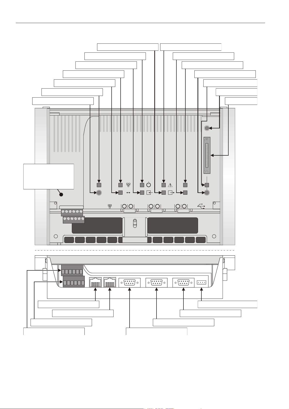
OVERVIEW OF HARDWARE
binary output (terminals 9+10) LED (yellow)
(LED = application has closed contact)ON
power supply LED (green)
(LED = power supplied)ON
binary input (terminals 3+4) LED (yellow)
(LED = input closed)ON
Ethernet link LED (yellow)
(LED = Ethernet link is enabled)ON
Ethernet activity LED (yellow)
(LED = Ethernet active)ON
LonWorks service LED (yellow)
(for meaning of LED behavior, see Table 1)
LonWorks service button
(pushing broadcasts service pin message)
binary output (terminals 7+8) LED (red)
(LED = watchdog has closed contact)ON
LED2 (currently unused)
LED1 (currently unused)
Compact Flash Card (CFC) release button
(push before removing CFC)
(LED = CFC may be removed)OFF
CFC LED (red)
reset button
CFC slot
ATT ENT ION:
Never unscrew and
dismount the inner
metallized cover while
the XL Web is powered!
Danger of short-circuiting!
LonWorks interface (8-position,
unshielded RJ45 connector jack)
lower terminal block (removable)
(terminals 1 thru 6)
upper terminal block (removable)
(terminals 7 thru 12)
LON
LON
71829
10 1112
5
3
6
4
Ethernet interface (8-position,
shielded RJ45 connector jack, CAT5)
Fig. 1. Hardware features (top and front view)
21
RS232C serial interface, port 2
(standard male 9-position sub-D)
RS232C serial interface, port 1
(standard male 9-position sub-D)
L1
CF
L2
3
USB interface
RS232C serial interface, port 3
(standard male 9-position sub-D)
EN1B-0256GE51 R0609
2
Page 3
EXCEL WEB CONTROLLER – INSTALLATION INSTRUCTIONS
Terminal Blocks
The Excel Web features two rows of removable terminal
blocks (located at the front left-hand side; see Fig. 1 on page
2) for the connection of cables to the two binary outputs and
the binary input as well as for connecting L
power supply. A nearby sticker provides an overview of the
terminal assignment (see Fig. 2).
!
7
8
9310
24V
~ 0
1
2
4
ONWORKS and the
LON
12
11
LON
5
6
24Vac/dc, +/-20%,
10VA, 50/60Hz, IP 20
D-71101 Schoenaich
Made in Germany
CE
Fig. 2. Terminal assignment sticker
Maximum torque for fastening the wiring terminal screws is
0.5 Nm (4.5 lb-in).
Table 1 provides a more-detailed explanation of the terminals
and their functions.
Table 1. Overview of terminals and functions
term. function
1+2 power supply (24 Vac ± 20%, 19.2 to 38 Vdc)
a binary input (normally-open, 36 Vdc; pin 4 is the
signal ground), freely configurable (using CARE 7)
3+4
5+6 LONWORKS
7+8
9+10
11+12 LONWORKS
to read input from either 1) a field device or 2) a
collective alarm input or 3) a 2
controller whose duties it could then assume in the
event of its failure
a binary output / "watchdog relay" (SPDT, normally
closed, 24 Vac, max. 2 A permanent load), permanently configured to write output to an alarm
device (which can then signal that Excel Web is
malfunctioning)
a binary output (potential-free contact, SPST,
normally-open, 24 Vac, max. 2 A permanent load),
freely configurable (using CARE 7) to write output
to either 1) a field device or 2) a 2
controller which could then assume the 1
Web's duties in the event of its failure
nd
Excel Web
nd
Excel Web
st
Excel
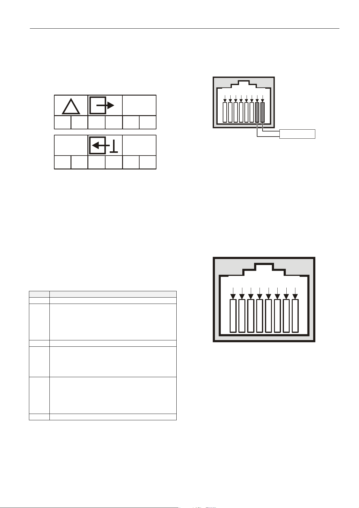
LonWorks Interface
The Excel Web is equipped with a LonWorks interface
(specifically: an RJ45 jack) permitting communication on
L
ONWORKS networks.
5
8 7 6
Fig. 3. LonWorks interface (RJ45 jack)
There are two methods of connecting the Excel Web controller to the L
method can be used):
• via terminals 5+6 and 11+12 of the terminal blocks (see
Fig. 1 on page 2); and/or
• via the corresponding jack located to the right of the
terminal blocks (see Fig. 3).
See also section "LonWorks Service LED and Service Button"
on page 5 for details on the corresponding L
LED and one L
ONWORKS networks (both or either connection
ONWORKS service button.
432 1
LonWorks
ONWORKS service
Ethernet Interface
The Excel Web controller is equipped with a 10/100-Mbaud
Ethernet interface (specifically: an RJ45 jack) permitting communication (as per IEEEC 802.3) on BACnet/IP networks.
8 7 6
Fig. 4. Ethernet interface
When thus connected, the user sitting at a platform hosting
EBI can thus e.g. view and edit the time programs, trend
values, etc. of the other devices in the BACnet/IP network.
This Ethernet jack conforms to the specifications of the
following two Ethernet sub-standards:
• 100Base-TX (twisted pair / star wiring; 100 Mbaud
Ethernet based on Manchester signal encoding over
category 5 or better twisted pair cable; max. segment
length = 100 meters) and
• 10Base-T (twisted pair / star wiring; 10 Mbaud Ethernet
based on Manchester signal encoding over category 3 or
better twisted pair cable; max. segment length =
100 meters).
5
432 1
EN1B-0256GE51 R0609
3
Page 4

EXCEL WEB CONTROLLER – INSTALLATION INSTRUCTIONS
RS232C Serial Interface Ports
The Excel Web controller is equipped with three male 9-pin
sub-D jacks into which corresponding female 9-pin sub-D
plugs can be inserted for various different purposes (see
following sub-sections). These ports allow data transmission
rates of 9.6, 19.2, 76.8, or 115.2 kBaud (the default).
Fig. 5. RS232C serial interface
Using CARE 7, the user can configure the specific desired
data transmission rate of each individual RS232C port; it is
thus possible for the three ports to operate simultaneously at
three different rates.
Port 1 (Factory Service Interface)
Port 1 is intended for the connection (as needed) of a platform for the purpose of servicing (in the factory, only) the
Excel Web controller. In this context, "servicing" comprises a
group of different activities including:
• updating portions of the Excel Web controller's Operating
System (namely: LINUX, BACstack, Apache WebServer) and
• diagnostics (Linux, firmware).
Port 2 (Browser Interface)
Port 2 is intended for the connection (as needed, or permanently) of a (portable) platform (which must host an
Internet Explorer-compatible internet browser) for the purpose
of operating the Excel Web controller.
This requires the establishment of a remote connection via
RS232 on the PC, plus a null modem cable (RS232 crossover cable). Because it offers a much higher speed, we
recommend instead using the USB interface.
Port 3 (Modem Interface)
Port 3 is intended for the permanent connection (if needed) of
a modem (e.g. an analog modem, an ISDN adapter, or an
GSM adapter) for the purpose of communicating with other
front-ends (e.g. 3
rd
-party BACnet front-ends) via modem.
CF Port LED, Request Button, and Slot
The Excel Web controller features a slot (type-II socket) into
which type-II Compact Flash Cards (CF cards) − but also
type-I CF cards − can be inserted.
Inserting a CF card allows the Excel Web controller's internal
memory (for storing trend records) to be increased.
CF cards having a variety of storage sizes are available from
wholesale and retailer dealers.
NOTE: Insert the CF card carefully and make sure that it
has the proper orientation (see Fig. 6).
narrow
notch
wide
notch
CF
Fig. 6. Inserting a CF card into the slot
NOTE: Before removing a CF card, always first push the CF
request button and wait (usually just a few seconds)
until the CF LED turns OFF. Violating this rule could
interrupt the transfer of data onto the card.
NOTE: Upon inserting a CF into a running Excel Web, the
CF will be reformatted, if necessary. Specifically: If
the CF already has the format EXT3, it will not be
formatted; otherwise, it will be formatted, and any
data already present on it will be irretrievably lost.
USB Interface Downloads
The Excel Web controller is equipped with a USB port into
which a standard USB type-A connector can be inserted. This
USB interface is the recommended interface for downloading
applications and firmware via CARE 7 and for operating the
Excel Web controller via Internet Browser in parallel to an
Ethernet connection. The following USB host networking
adapter has been approved: BELKIN DIRECT CONNECT
(BELKIN order no.: F5U104 or F5U104G at www.belkin.com
).
12.5 mm
Fig. 7. USB interface
EN1B-0256GE51 R0609
4
Page 5

EXCEL WEB CONTROLLER – INSTALLATION INSTRUCTIONS
Alternatively, either of the following three adapters can also
be used: SMC 2208USB/ETH; SMC 2209USB/ETH; or D-Link
DUB-E100.
See section "Option 1: USB (recommended)" on page 9.
LEDs and Buttons
LonWorks Service LED and Service Button
The Excel Web controller is equipped with a LONWORKS
service LED and a L
marked "LON" (see also Fig. 1 on page 2). They are used for
commissioning the Excel Web controller and for
troubleshooting.
LonWorks Service Button
When the L
ONWORKS service button is pressed, the service
pin message is broadcast on the L
L
ONWORKS tools currently connected to the LONWORKS
network will receive this message.
LonWorks Service LED
The L
ONWORKS service LED can display various behaviors
having different meanings (see Table 2).
ONWORKS service button, together
ONWORKS network, and all
Power Supply LED
The LED marked " " indicates whether or not the Excel
Web controller is currently under power. Specifically, when it
is lit, the controller is under power; when it is dark, the
controller is not under power.
Binary Input (terminals 3+4) LED
The LED marked " " indicates the state of the binary input
(which is a normally-open contact) located at terminals 3 and
4. Specifically, when it is lit, the binary input is closed; when it
is dark, the binary input is open.
Binary Output (terminals 7+8) LED
The LED marked " " indicates the state of the binary output
("watchdog" relay) at terminals 7 and 8 (which is a normally
closed contact). Specifically, when it is lit, the alarm contact is
open; when it is dark, the alarm contact is closed.
For a detailed description of the "watchdog" relay behavior,
see Excel Web User Guide (EN2B-0289GE51).
Binary Output (terminals 9+10) LED
The LED marked " " indicates the state of the binary
output at terminals 9 and 10 (which is a normally-open
contact). Specifically, when it is lit, this means that the
application has closed the relay; when it is dark, the relay is
open.
Table 2. L
1
2
3
4
5
6a
6b
6c
7
8
ONWORKS service LED behaviors / meanings
LED behavior meaning
LED remains OFF after
power-up.
LED is lit continuously after
first power-up.
LED flashes at power-up,
goes OFF, and then is lit continuously.
LED flashes briefly
periodically.
LED repeatedly blinks ON for
1 s and OFF for 1 s.
OFF for approx. 10 s. Afterwards, the service LED turns
ON and remains ON,
indicating completion of the
blanking process.
OFF for approx. 1 s.
Afterwards, the service LED
is lit continuously.
OFF for 1...15 s, depending
on application size and system clock. Afterwards, service LED repeatedly flashes
ON for 1 s and OFF for 1 s.
LED remains OFF after a
short ON duration.
LED flashes ON.
Defective Excel Web hardware
(e.g. power supply problems,
clock problems, or defective
Neuron Chip).
Defective Excel Web hardware.
Neuron chip lacks L
interface program. Remedy: Use
Excelon or LonMaker, set Excel
Web online.
Excel Web probably experiencing
continuous watchdog resets, or
external memory or EEPROM is
corrupt.
Excel Web is unconfigured but
has an application. Remedy:
Commission Excel Web using
CARE 7.
Return Excel Web to factory.
Return Excel Web to factory.
Excel Web is unconfigured but
has an application. Remedy:
Commission Excel Web using
CARE 7.
Excel Web is configured and
running normally.
Excel Web received a WINK
command from L
physical outputs are unaffected.
ONWORKS
ONWORKS; other
In case of a problem, check if the L
ONWORKS service LED's
behavior is changed by resetting the Excel Web controller
using the reset button. Please contact Honeywell if this does
not solve the problem.
Ethernet LEDs
The Excel Web controller is equipped with two Ethernet LEDs
(see also Fig. 1 on page 2).
Ethernet Link LED
The LED marked " " indicates the Ethernet link's status.
Specifically, it is lit whenever an Ethernet jack has been
inserted into the corresponding port and the software has
established the Ethernet link. It is dark when the link has been
disabled.
Ethernet Activity LED
The LED marked " ↔ " indicates whether or not the Ethernet
link is currently active. Specifically, when it flashes, this
means that signals are being transmitted / received on the
Ethernet network; when it is dark, no messages are being
transmitted/received.
LEDs L1 and L2
At present, these LED's are not in use.
EN1B-0256GE51 R0609
5
Page 6

EXCEL WEB CONTROLLER – INSTALLATION INSTRUCTIONS
141.5 +
.
3
36.
5
Reset Button
The reset button can be pressed only using a long, thin tool
(e.g. a screwdriver). Pressing it reboots the Excel Web
controller's operating system and restarts the application.
MOUNTING
Before Installation
IMPORTANT
To allow the evaporation of any condensation resulting
from low shipping / storage temperatures, keep the
controller at room temperature for at least 24 h before
applying power.
US requirement, only: This device must be installed in
a UL-listed enclosure offering adequate space to
maintain the segregation of line voltage field wiring
and Class 2 field wiring.
In order to meet the criteria for CE certification, the XL1000
controller must be mounted inside an electrical panel.
Dimensions
Allow 30 mm clearance
for opening swivel cover.
LON
LON
Allow 30 mm
clearance for
accessing interfaces.
CF
321
278
4.4 +/- 0.3
190
0.6
60.6
DIN Rail Mounting/Dismounting
17 mm
(center-to-center distance = 100 +3 mm)
Fig. 9. Housing base (view from below)
The Excel Web controller can be mounted onto DIN rails as
follows (refer also to Fig. 10):
1. Hang the upper slot onto the upper DIN rail.
2. Swing the unit down until it is flush with the lower DIN rail.
3. Slide the fastening plate and corresponding screw in the
oval hole up against and behind the bottom edge of the
lower DIN rail and screw it firmly into place.
4. If necessary, the swivel cover can be locked by inserting
a small string lock, lead seal, or screw into either one of
the two openings provided.
The unit is dismounted by loosening the fastening plate and
lifting the unit out of place.
slots for DIN rails
fastening
plate
/- 0
12
220 +/- 0.3
5 +/- 0.3
Fig. 8. Dimensions (in mm)
The Excel Web has the following dimensions (W x L x H):
278 x 190 x 61 mm. Its housing conforms to IP20. Its pollution
degree (2) makes it suitable for use in residential controls,
commercial controls, in a clean environment, or non-safety
controls for installation on or in appliances.
The Excel Web is suitable for mounting on a standard rail
(DIN EN 50022-35 x 7,5), on walls or in panels, as well as for
installation in appropriately-sized wiring cabinets or fuse
boxes. Allow sufficient clearance (approx. 30 mm) to access
the interfaces and to open the swivel cover (see Fig. 8).
step
1
100 mm
fastening
plate
step
step
2
3
step
4
Fig. 10. Mounting the Excel Web on to two DIN rails
Wall/Panel Mounting/Dismounting
The Excel Web controller can be mounted on walls or in
panels in any desired orientation. However, mounting the
Excel Web controller upside down on ceilings should be
avoided, insofar as the swivel cover would then swing open.
EN1B-0256GE51 R0609
6
Page 7

EXCEL WEB CONTROLLER – INSTALLATION INSTRUCTIONS
4.4 +/- 0.3
36.5
190
141.5 +/- 0.3
12
29 29
Fig. 11. Drilling template (view from above)
220 +/- 0.3
278
Swivel Cover Lock
The swivel cover can be locked by inserting a small string
lock, lead seal, or screw into either one of the two openings
provided (see Fig. 10).
POWER SUPPLY
Wiring
NOTE: All wiring must comply with applicable electrical
standards and ordinances. Refer to job or manufacturers’ drawings for details. Local wiring guidelines (e.g. VDE 0100) may take precedence over
recommendations provided in these installation
instructions.
• Power supply: 24 Vac [±20%], 50 or 60 Hz, or
24...38 Vdc, galvanically isolated;
• Power consumption = max. 10 VA (USB unloaded);
• Excel Web® and 24 Vac field devices can obtain their
power from the same transformer;
• Several Excel Web controllers can share a single
common transformer. In this case, you must ensure that
terminal 1 of each of the Excel Web controllers is
connected to 24 V and terminal 2 is connected to the
minus pole (optionally, terminal 2 can additionally be
connected to the earth) (see also Fig. 12).
• The power supply LED (see section "Power Supply LED"
on page 5) indicates whether power is being supplied.
• In the event you wish to connect one of the 24 Vac pins
to the earth ground, connect it via terminal 2 of the lower
removable terminal plug (see also Fig. 12).
Table 3. Cable sizing (use only copper cables)
cross-sectional area
type of signal
24 Vac power
supply
low-voltage*
*0...10 V sensors, totalizers, binary inputs, 0...10 V signals
for actuators, etc.
≤ 300 ft
(100 m)
16 AWG
(1.5 mm
14 – 18 AWG (2.5 – 0.75 mm2)
2
)
≤ 550 ft
(170 m)
14 AWG
(2.5 mm2)
≤ 1300 ft
(400 m)
-
Power is supplied via terminals 1 and 2 of the lower removable terminal plug. The removable terminal plug permits
individual Excel Web controllers to be disconnected from the
power supply without disturbing the operation of other devices
powered by the same source.
NOTE: Do not reverse the polarity of the power connection
cables, and avoid ground loops (i.e. avoid
connecting one field device to several controllers) as
this may result in short-circuiting.
5 +/- 0.3
Transformer Data
Table 4. 1450 series transformers data
part #
1450 7287
-001 120 Vac 24 Vac, 50 VA
-002 120 Vac
-003 120 Vac
-004 240/220 Vac 24 Vac, 50 VA
-005 240/220 Vac
-006 240/220 Vac
Table 5. Overview of CRT Series AC/DC current
transformer max. AC current max. DC current
CRT 2 2 A 0.5 A = 500 mA
CRT 6 6 A 1.3 A = 1300 mA
CRT 12 12 A 2.5 A = 2500 mA
primary side secondary side
2 x 24 Vac, 40 VA, and
100 VA from separate
transformer
24 Vac, 100 VA, and 24 Vdc,
600 mA
2 x 24 Vac, 40 VA, and
100 VA from separate
transformer
24 Vac, 100 VA, and 24 Vdc,
600 mA
primary
voltage
24 V~
1
24 Vac
(-)
transformer
2
optional
Fig. 12. Connection of Excel Web
Lightning Protection
Please contact your local Honeywell representative for
information on lightning protection.
RIN-APU24
The RIN-APU24 Uninterruptable Power Supply can be
directly wired to an Excel Web.
See RIN-APU24 Uninterruptable Power Supply – Mounting
Instructions (EN0B-0382GE51) for a detailed wiring diagram.
EN1B-0256GE51 R0609
7
Page 8
EXCEL WEB CONTROLLER – INSTALLATION INSTRUCTIONS
LONWORKS COMMUNICATIONS
General Information
The Excel Web controller is equipped with a free-topology
transceiver (FTT10A or FT-X1) for communication (at a data
transmission rate of 78 Kbaud) on L
(using the LonTalk protocol).
The L
ONWORKS network is insensitive to polarity, eliminating
the possibility of installation errors due to miswiring.
Different network configurations (daisy-chain, loop, and star
configurations, or any combination thereof) are possible (see
also Excel 50/500 L
ONWORKS Mechanisms Interface
Description, EN0B-0270GE51).
Connecting to the LONWORKS Network
IMPORTANT
Do not bundle wires carrying field device signals or
L
ONWORKS communications together with high-voltage
power supply or relay cables. Specifically, maintain a
min. separation of 3 inches (76 mm) between such
cables. Local wiring codes may take precedence over
this recommendation.
IMPORTANT
Try to avoid installing in areas of high electromagnetic
noise (EMI).
Cable Types
The unit must be wired to the L
• level IV 22 AWG (Belden part number 9D220150)
or
• plenum-rated level IV 22 AWG (Belden part number
9H2201504) non-shielded, twisted-pair, solid-conductor
wire.
When possible, use Honeywell AK3781, AK3782, AK3791, or
AK3792 cable (US part numbers). See Excel 50/5000
L
ONWORKS Mechanisms, EN0B-0270GE51, for details,
including maximum lengths.
Use wire with a minimum size of 20 AWG (0.5 mm
maximum size of 14 AWG (2.5 mm
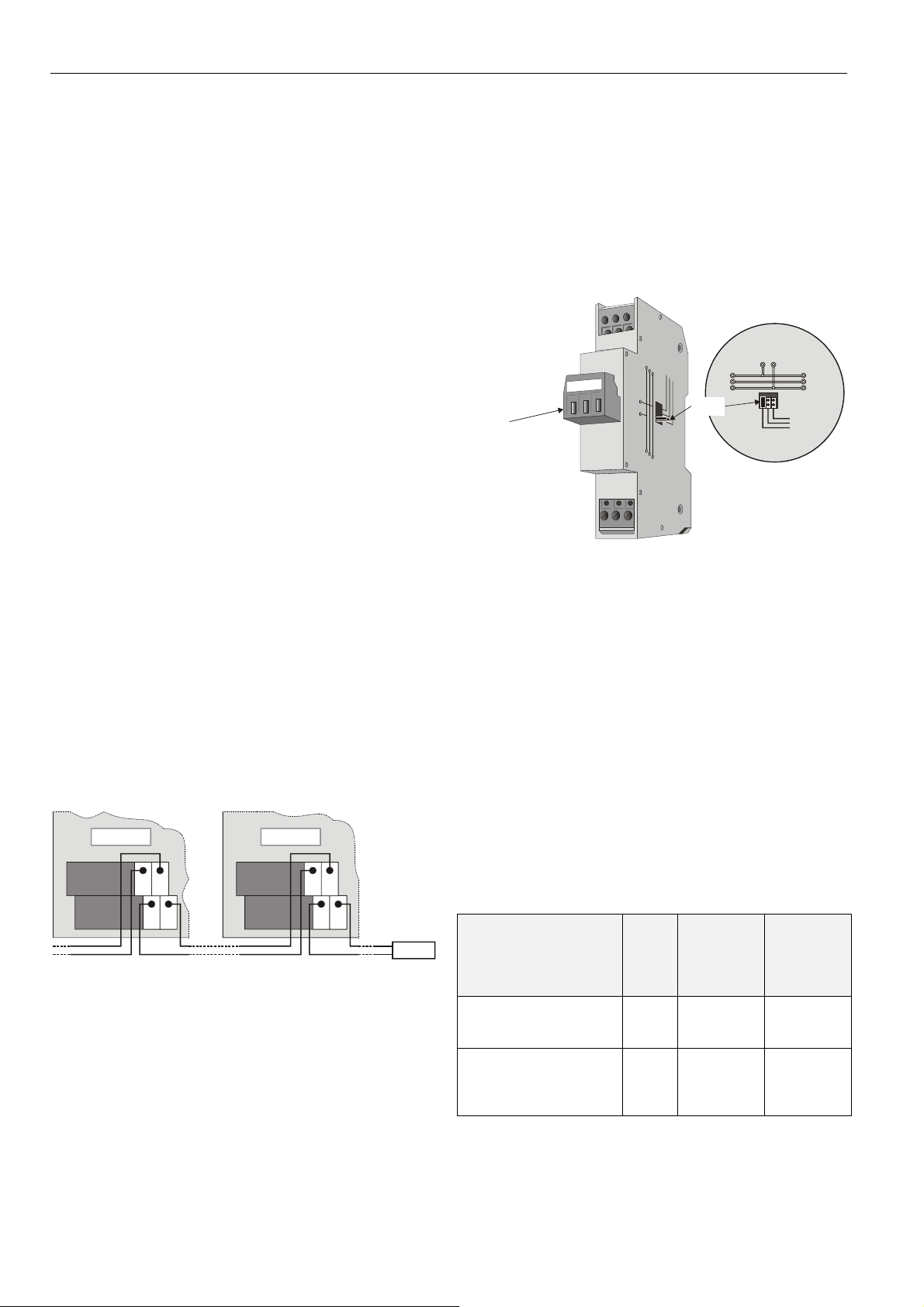
XL Web XL Web
12 12
11 11
55
66
Fig. 13. Connection to L
termination module (here: daisy-chain network
configuration)
The Excel Web controller can be connected to the L
network via terminals 5+6 and 11+12 of the removable
terminal plug or via the L
"LonWorks Interface" on page 3).
ONWORKS jack (see also section
ONWORKS® networks
ONWORKS network using either
2
2
).
ONWORKS network and
) and a
termination
module
ONWORKS
This permits individual Excel Web controllers to be connected
/ disconnected from the L
ONWORKS network without disturbing
the operation of other devices.
Depending upon the chosen network configuration, one or two
terminations may be required.
Two different L
• L
ONWORKS termination module, order no.: 209541B
• L
ONWORKS connection / termination module
ONWORKS termination modules are available:
(mountable on DIN rails and in fuse boxes),
order no.: XAL-Term
l
l
e
w
removable screw-type
3-pole terminal block
Fig. 14. L
ONWORKS connection and termination module
y
e
n
o
H
m
r
e
T
-
L
A
X
4
3
L
L
O
O
N
N
shield shield
plug-in
jumper
34
1
06
Termination
BINARY INPUT AND OUTPUTS
Wiring
When wiring the two binary outputs and the binary input, use
a min. size of 20 AWG (0.5 mm
(2.5 mm
2
). The max. length of all cables is 400 m.
Two wires with a total thickness of 14 AWG can be twisted
together and connected using a wire nut (include a pigtail with
this wire group and attach the pigtail to the individual terminal
block). Deviations from this rule can result in improper
electrical contact. Local wiring codes may take precedence
over this recommendation.
Binary Input
The Excel Web controller's binary input (a normally-open
contact) is not galvanically isolated. It is suitable for connection with / signalling via 0...36 Vdc voltage or external
resistor or dry contact.
Table 6. Binary input specifications
purpose assigned to
binary input by user using
CARE 7
high-level detection (i.e.
detection that binary input
has opened)
low-level detection (i.e.
detection that binary input
has closed)
2
) and a maximum of 14 AWG
at
resistance at
binary con-
tact (ext.
resistor or
dry contact)
> 10 kΩ or
open input
< 400 kΩ or
when binary
input shorted
voltage
binary
input
3.8 to
36 Vdc
0 to 0.8
Vdc
voltage at
open terminals = 5 V
current from
shorted
terminals =
2 mA
5
LON
FTT/LPT Bus
FTT/LPT Free
Park Position
info
EN1B-0256GE51 R0609
8
Page 9

EXCEL WEB CONTROLLER – INSTALLATION INSTRUCTIONS
The binary input is protected against miswiring. Specifically, it
is protected against voltages of up to 29 Vac; when miswired,
the Excel Web controller is unable to detect a valid input
signal.
Binary Outputs
The Excel Web controller is equipped with two binary outputs.
Hardware Limits
• A min. current of 50 mA is required to ensure a reliable
contact.
• The binary outputs are designed for a max. continuous
current of 2 A.
• Switching voltage = 24 Vac ± 20%.
NOTE: If inductive components are to be connected to the
binary outputs and if these binary outputs switch
more often than once every two minutes, these
components must be prevented from causing
harmful interference to radio or television reception
(conformance with EN 45014).
ENGINEERING, COMMISSIONING
Please refer also to CARE 7 User Guide (Product Literature
No.: EN2B-0182GE51) for more information.
Required Preparations
In order to access (with a laptop or PC) the Excel Web via
Ethernet/IP for the first time, you may employ any one of the
following three options:
Option 1: USB (recommended)
This USB interface is the recommended interface for
downloading applications and firmware via CARE 7. The
following USB host networking adapter has been approved:
BELKIN DIRECT CONNECT (BELKIN order no.: F5U104 or
F5U104G at www.belkin.com
For access via USB, the Excel Web has a permanent default
IP address 192.168.252.20 and Network Mask
255.255.255.0. Your PC's IP address must match the Excel
Web controller's default IP address subnet: We recommend
using 192.168.252.21 and Network Mask 255.255.255.0.
Option 2: Dedicated Ethernet Interface
For access via Ethernet, the Excel Web has a permanent
default IP address 192.168.253.20 and Network Mask
255.255.255.0. Your PC's IP address must match the Excel
Web controller's default IP address subnet: We recommend
using 192.168.253.21 and Network Mask 255.255.255.0.
If the laptop or PC with which you wish to access the Excel
Web via Ethernet/IP is not already equipped with an
integrated Ethernet Card, or if you want to leave the IP
settings of the integrated network card unchanged, buy and
install (into your laptop or PC) an external Ethernet network
card, e.g. Devolo MicroLink LAN USB Network Adapter
(typical retail price: €30).
Option 3: Standard Ethernet Interface
For access via Ethernet, the Excel Web has a permanent
default IP address 192.168.253.20 and Network Mask
255.255.255.0. Your PC's IP address must match the Excel
).
Web controller's default IP address subnet: We recommend
using 192.168.253.21 and Network Mask 255.255.255.0.
Change the (factory-set) configuration of the integrated
Ethernet card so as to match the Excel Web IP address and
IP subnet.
When using this default address, you must ensure that you
have only one powered-up Excel Web controller on your
Ethernet; otherwise, communication will fail because all Excel
Web controllers have the same permanent default IP
address. Alternatively, you can use an Ethernet cross-over
cable between your PC and the Excel Web controller rather
than having your PC and the Excel Web controller both
connected to a LAN. In any case, your PC's IP address must
match the Excel Web controller's default IP address subnet.
We recommend using 192.168.253.21 and Network Mask
255.255.255.0.
NOTE: In order to (subsequently) operate on your standard
Ethernet network (again), you will have to change
the configuration back to the previous settings.
Engineering, Downloading, and
Commissioning Procedure
1. The user must first create (on a Windows-compatible
platform, using CARE 7) the application data for the Excel
Web controller. Before downloading the application, it can
be tested using the simulator (called "LIVE CARE
OFFLINE").
2. The user then downloads (from the Windows-compatible
platform) the application data (created in step 1) into the
Excel Web controller (typically via the USB interface).
After the very first set-up, the Excel Web controller gets
the final IP address which you assigned offline during the
engineering process using CARE. You can use this final
IP address for further application / firmware downloads
provided all of the Excel Web controllers are powered up.
3. Typically, testing and debugging (using the LIVE CARE
functionality of CARE 7) is then performed (in a simulated
environment, i.e. with the Excel Web controller connected
to a test board).
4. The Excel Web is then physically installed in the wall,
wiring cabinet, etc. In the course of doing this, the Excel
Web controller's terminal blocks are wired and the
corresponding RJ45 jacks are inserted into its L
interface and the Ethernet interface. If desired (i.e. if the
Excel Web controller is to later communicate by modem,
too), the corresponding jack can be inserted into the
corresponding RS232C interface (namely: Port 3).
ONWORKS
EN1B-0256GE51 R0609
9
Page 10

EXCEL WEB CONTROLLER – INSTALLATION INSTRUCTIONS
5. The user must now commission the Excel Web and the
field devices to which it is connected via L
ONWORKS (i.e.
their NV's must be bound and configured). This is performed with the same platform hosting CARE 7 as in step
3, via any L
11+12 or via the RJ45 L
ONWORKS access (e.g. terminals 5+6 and
ONWORKS jack).
6. Typically, the user again tests and debugs the Excel Web
controller – this time in its actual working environment.
Testing and debugging is again performed using the LIVE
CARE functionality of CARE 7. Optionally, testing can be
performed using an Internet browser on a laptop or PC
with 800x600 resolution or higher. The tester/debugger
can now perform audio-visual checking to see if the field
devices are responding as predicted/desired.
7. Engineering, installation, and commissioning are now
complete. The corresponding jack can now be removed
from the USB port. The Excel Web controller begins
operation.
Protocolling
In the context of the Excel Web controller, "protocolling"
means creating a log of the values or states of the data-points
which have been assigned to this particular Excel Web
controller. Using the browser interface, the user must place
the corresponding data-points into "trend." If, at some later
point in time, i.e. after lengthy operation, a protocol of the
Excel Web controller's history is desired, the corresponding
trend data can be generated, viewed, and downloaded (in
CSV format) via the browser interface. For the storage of
larger amounts of trend data (more than 64,000 trend entries
– corresponding to approx. 2 MB), a CF card (see section "CF
Port LED, Request Button, and Slot") can be used.
Updating Firmware
If, at some later point in time, i.e. after the release of a new
version of the firmware, the user wishes to download the new
firmware into the Excel Web, this can be done using CARE 7
(via either USB or Ethernet) or using EBI (via Ethernet).
Manufactured for and on behalf of the Environmental and Combustion Controls Division of Honeywell Technologies Sàrl, Rolle, Z.A. La Pièce 16, Switzerland by its Authorized Representative:
Automation and Control Solutions
Honeywell GmbH
Böblinger Strasse 17
71101 Schönaich, Germany
Phone: (49) 7031 63701
Fax: (49) 7031 637493
http://ecc.emea.honeywell.com
Subject to change without notice. Printed in Germany
EN1B-0256GE51 R0609
 Loading...