

Page 1

Compact I/O Module
XIO-8AI UNIVERSAL ANALOG INPUT MODULE
LON Interface:
Transceiver: FTT10A free topology.
Neuron: 3150, 64k Flash.
Data format: standard network variables (SNVT).
Transmission rate: 78 kBit/s.
Maximum Length:
line topology 8858 ft. (2700 m) / 64 nodes.
free topology 1640 ft. (500 m) / 64 nodes.
Cabling: twisted pair.
Temperature Ratings:
Operating: 23° F to 131° F (-5° C to +55° C).
Storage: -4° F to +158° F (-20° C to +70° C).
Dimensions (W x H x D):
2.0 x 2.7 x 2.6 in. (30 x 68 x 65 mm).
Weight: 4.4 ounces (126 g).
INSTALLATION INSTRUCTIONS
GENERAL
The Honeywell XI0-8AI Universal LON® Analog Input Module
is a LON module with 8 configurable temperature or voltage
inputs to record temperatures and voltages of passive and
active sensors for example, electrical ventilation and mixing
valves, valve positions etc. The recorded counted
measurands are produced in different formats. Temperature,
resistance, percentage and voltage can be read out
depending on the setting for each input, and bound to other
LonMark
measuring ranges are done by LNS
voltage for active sensors can be provided by the module.
®
devices. The setting of sensor characteristics and
®
-Plugin. The supply
SPECIFICATIONS
Electrical Ratings:
Supply Operating Voltage: 20 to 28 V AC/DC.
Current Consumption: 57 mA (AC) / 30 mA (DC).
Duty cycle: 100%.
Recovery time: 550 ms.
Terminal Blocks:
Supply and Bus: 16 AWG (1.5 mm
(Terminal block and strapping plug included in packing).
Analog Inputs: 14 AWG (2.5 mm
2
).
2
).
Mounting Position: Any.
Mounting: DIN rail per EN 50022.
Input:
Temperature Range: selectable.
NOTE: Temperature input for all sensors is in the range of
40 Ω up to 4 MΩ.
Resolution: 0.2 K.
Error: approximately ± 0.4° F (±0.2° C).
Voltage input: 0 to 10 V DC.
Resolution: 10 mV (0.0 to 100%).
Error: approximately ±100 mV.
Construction Material:
Housing and Terminal Blocks: Polyamide 6.6 V0.
Faceplate: Polycarbonate.
Protective Circuitry:
Operating Voltage: polarity reversal protection.
Protection:
IP40 housing DIN 40050.
IP20 terminal blocks DIN 40050.
Approvals:
UL 916, Standard for Energy Management Equipment.
European Community Mark (CE) Listed.
95-7716—1
Page 2
COMPACT I/O MODULE
SAFETY INSTRUCTIONS
NOTES REGARDING DEVICE DESCRIPTION
These instructions include indications for use and mounting of
the device. In case of questions that cannot be answered with
these instructions, please consult the product supplier or
manufacturer. It is the responsibility of the equipment installer
to ensure that all federal, state and local codes are followed.
SAFETY INSTRUCTIONS
• Keep these Installation Instructions for industrial safety and
the prevention of accidents.
• Only qualified personnel shall do mounting and installation
work with these devices, see section titled “Qualified
Personnel”.
• The information in these instructions must be read and
understood by every person using this device.
QUALIFIED PERSONNEL
Qualified personnel in the sense of these instructions are
persons who are well versed in the use and installation of
such devices and whose professional qualification meets the
requirements of their work.
This includes, for example:
• Qualification to connect the device according to applicable
specifications and regulations, and a qualification to put
this device into operation, to power it down, or to activate it
by respecting the internal directions.
• Knowledge of safety rules.
• Knowledge about application and use of the device within
the equipment system.
BEFORE INSTALLATION
INSTALLATION
CAUTION
Electrical installation and device termination shall
be accomplished by qualified persons only, by
respecting all applicable specifications and
regulations.
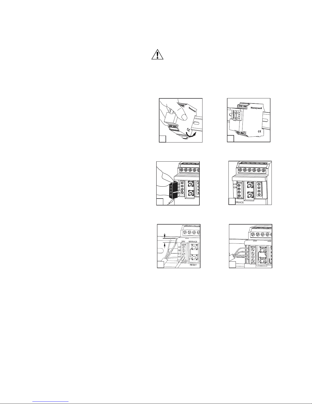
1. Power down the equipment. Mount the module on the
DIN rail.
24V
S
E
R
V
IC
E
24
1b
2b
V
+24V
G
N
D
E1
E1
E2
E2
SE
R
VIC
E
RESET
O
N
M25061
24V
SERVICE
24V
E1
E2
RESET
ON
SERVIC
E
ON
RESET
1a
M25060
2. Plug in the terminal block for bus connection.
24V
SERVICE
SERVICE
2a
3. Prepare the cable for bus connection:
RESET
M25062
+24V
GND
E1
E2
M25063
1. Unpack the XIO-8AI Universal LON Analog Input
Module.
2. Check the equipment and report any damage to a
Honeywell representative.
3. Read all of these instructions and ensure they are
understood.
MOUNTING
Mount the XIO-8AI Universal LON Analog Input Module on
standard DIN rail per DIN EN 50022 (1.35 x 0.3 in. [35 x
7.5 mm]), in junction boxes and/or on distribution panels.
0.2 in.
(5 mm)
24V
SERVICE
3a
M25040
3b
a. Remove about 0.75 in. (2 cm) of the plastic cable
sheath.
b. Strip 0.2 in. (5 mm) insulation from each wire. Put a
wire end sleeve to stranded wires.
c. Insert the wire to the respective contact and secure
it by screwing down the contact screw.
d. Wire cross section of the 4 pole terminal block bus/
mains connection:
(1) Maximum 16 AWG (1.5 mm
(2) Maximum 18 AWG (1.0 mm
2
) single wire.
2
) stranded wire.
(3) Wire diameter minimum 28 AWG (0.3 mm) up to
16 AWG (1.4 mm).
M25064
95-7716—1 2
Page 3
COMPACT I/O MODULE
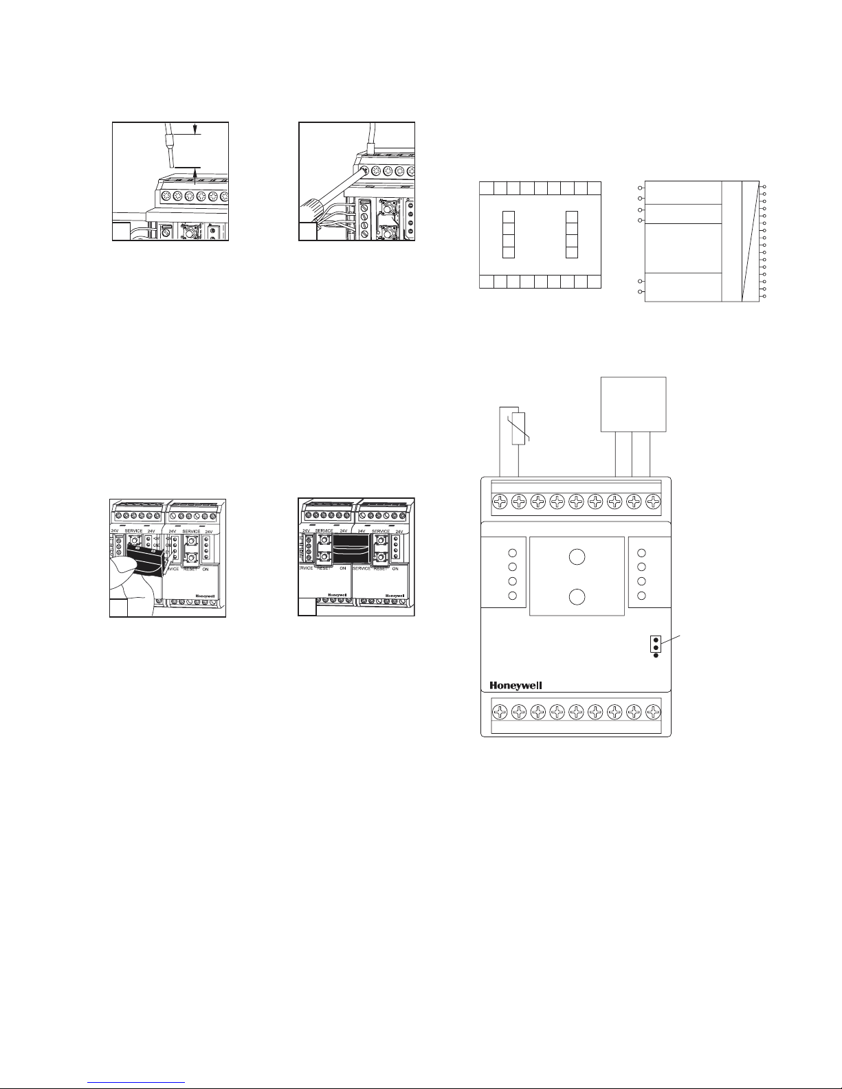
4. Prepare cable for module connections.
0.3 in.
(7 mm)
24V
SERVICE
2
24V
SERVICE
24V
4a
M25041
4b
M25065
a. Strip the wires by 0.3 in. (7 mm). Put a wire end
sleeve on stranded wires.
b. Insert the wire into the respective module contact
and secure it by screwing down the contact screw.
c. Wire cross section of the 4 pole terminal block bus/
mains connection:
(1) Maximum 12 AWG (4.0 mm
(2) Maximum 14 AWG (2.5 mm
2
) single wire.
2
) stranded wire.
(3) Wire diameter minimum 28 AWG (0.3 mm) up to
10 AWG (2.7 mm).
5. The module can be aligned without interspace. Use the
strapping plug to connect bus and supply voltage when
the modules are mounted in series. The modules can
be mounted in series without interspace. The maximum
number of modules connected in series is 15, with each
group needing an external power supply.
TERMINATION
Fig. 1 shows the termination points of the XIO-8AI.
+24V
GND
E1
E2
S
+24V
GND
E-bus 1
E-bus 2
0 - 10V
24V
FTT-10A
Inputs:
voltage 0-10 V
universal
temperature sensor
40 Ohm - 5 MOhm
Outputs:
S
voltage 15 VDC
S
or 24 VAC/DC
active
sensor
GND
Ub
S
C
81CC72CC63CC54CCS
24 V AC/DC
+24V
GND
E1
E2
GND
E-bus 1
E-bus 2
Fig. 1. Termination diagram for XIO-8AI.
passive
sensor
8 C 7 C 6 C 5
8
D
C
7
C
6
C
5
C
4
C
3
Neuron 3150
C
2
C
1
C
A
M25042
5a
+24V
GND
E1
E2
M25066
5b
+24V
GND
E1
E2
M25067
24V
+24V
GND
E1
E2
x10
x1
SERVICE
24V
+24V
GND
E1
E2
ON
XIO-8AI
1
C
2C3C 4
CS
Fig. 2. XIO-8AI Termination example.
Jumper below
the faceplate
M25044
3 95-7716—1
Page 4

COMPACT I/O MODULE
JUMPER POSITIONS
Fig. 3 illustrates the two jumper positions for the voltage
supply of active sensors.
+24V
GND
E1
E2
24V
SERVICE
24V
+24V
GND
E1
E2
Jumper below
SERVICE RESET ON
the faceplate
Jumper in
bottom position
contacts S
= 15 VDC
(factory setting)
+24V
GND
E1
E2
24V 24V
+24V
GND
E1
E2
SERVICE
XIO-8AI
Jumper below
SERVICE RESET ON
the faceplate
Jumper in
top position
contacts S = A1
XIO-8AI
(24V AC/DC)
M25043
Fig. 3. XIO-8AI Jumper positions.
24V 24V
SERVICE
+24V
GND
E1
E2
SERVICE RESET ON
Fig. 4. Front panel diagram of XIO-8AI.
+24V
GND
E-bus 1
E-bus 2
24VAC/DC
1
24V
FTT-10A
Inputs:
Voltage 0-10V
Universal-
Temp. Sensor
40 Ohm - 4 MOhm
Outputs:
S
Voltage 15VDC
S
or 24VAC/DC
XIO-8AI
Analog Input
+24V
GND
E1
E2
XIO-8AI
M25068
D
8
C
7
C
6
C
5
C
4
C
Neuron 3150
3
C
2
C
1
A
C
WIRING
Wiring of the XIO-8AI must be accomplished in accordance
with federal, state, and local requirements. Figures 4 through
6 show sample diagrams of wiring of the XIO-8AI.
95-7716—1 4
02
85267 27076
S
2
S
1 JUMPER IN BOTTOM POSITION (FACTORY DEFAULT),
15 VDC OUTPUT.
2
JUMPER IN TOP POSITION, 24 VDC OUTPUT.
M25069A
Fig. 5. Side panel diagram of XIO-8AI.
Page 5

connectors
8C7C6C5 CS
SERVICE
+24V
GND
E1
E2
SERVICE RESET ON
XIO-8AI
1C2C3C4 CS
Sensor
+10 to +20V
Out
GND
24V 24V
+24V
GND
E1
E2
Fig. 6. Wiring example XIO-8AI with sensor.
Jumper
15V Standard
M25070
COMPACT I/O MODULE
UCPTHyst SNVT_temp_p
Setting of the hysteresis; the output variables nvoHigh and
nvoLow switch over when the hysteresis is expired (factory
setting 2 Kelvin).5; 1. counted measurand = 1.
Temp_1- 8 Objects
nvoTemp_1 - 8
SNVT_temp
nvoTempp_1 - 8
SNVT_temp_p
nvoPercent_1 - 8
SNVT_lev_percent
nvoVoltage_1 - 8
SNVT_volt_f
nvoResistance_1 - 8
SNVT_res_f
nvoHigh_1 - 8
SNVT_switch
SOFTWARE DESCRIPTION
The Node Object monitors and controls the functions of the
different objects in the device. It supports the basic functions
Object-Status and Object-Request required by LonMark.
Refer to Fig. 7 for a basic illustration of Node Objects. The
following objects are monitored by the Node Object.
nviRequest NVT_obj_request
nvoStatus SNVT_obj_status
nvoFileDirectory SNVT_address
Node Object
nviRequest
SNVT_obj_request
SCPTmaxSendTime
UCPTHyst
Fig. 7. XIO-8AI Node Object.
SCPTmaxSendTime SNVT_time_sec
All output variables described below will be issued at the
latest at the end of the preset period even without status
change.
Time settings: 0 timer function off-state
6553,8 s (factory setting 60 s)
nvoStatus
SNVT_obj_status
nvoFileDirectory
SNVT_address
M25045
nvoLow_1 - 8
SNVT_switch
UCPTTemp_Offset
UCPTSensor_tab
UCPTTempMax
UCPTTempMin
UCPTHighT
UCPTLowT
SCPTinvrtOut
SCPTminSendTime
SCPTminDeltaTemp
M25046
Fig. 8. XIO-8AI Temp Objects.
nvoTemp_1...8 SNVT_temp
The output variable supplies a value with format ° C
depending on the input signal of 0 to 10.0 V and the settings in
UCPTTempHigh and UCPTTempLow and/or the resistance of
the selected temperature sensor.
nvoTemp_1...8 SNVT_temp_p
See Temp_1...8 but with 0.01° C format.
nvoPercent_1...8 SNVT_lev_percent
The output variable supplies a value with format 0 to 100.0%
for voltage measurements depending on the input signal of 0
to 10.0 Volt.
nvoVoltage_1...8 SNVT_volt_f
The output variable supplies a value with format 0 to 10.0 Volt
for voltage measurements depending on the input voltage.
nvoResistance_1...8 SNVT_res_f
The output variable supplies a value with format Ohm
depending on the input signal of 40 Ohm to 4 MOhm.
5 95-7716—1
Page 6

COMPACT I/O MODULE
nvoHigh_1...8 SNVT_switch
When exceeding the temperature set in UCPTHighT the
output variable changes from 0,0 0 to 100,0 1. When underrunning the temperature set in UCPTHighT plus the hysteresis
set in UCPTHyst the output variable changes from 100,01 to
0,0 0.
UCPTSensor_tab
Temperature
° F (° C) Resistance Sensor Name
nvoLow_1...8 SNVT_switch
When under-running the temperature set in UCPTLowT the
output variable changes from 0,0 0 to 100,0 1. When
exceeding the temperature set in UCPTLowT plus the
hysteresis in UCPTHyst the output variable changes from
100,0 1 to 0,0 0.
UCPTTemp_Offset SNVT_temp
The respective measurand can be readjusted in steps of 0.1 K.
ST_ON
(Resistance)
ST_OFF
(Voltage)
Factory setting: NTC20k in the range-22° F to 266° F (-30° C to +130° C).
UCPTTempMax SNVT_temp Werk:
UCPTHighT SNVT_temp Werk:
+ 302° F (+150° C)
UCPTTempMin SNVT_temp Werk:
UCPTLowT SNVT_temp Werk:
- 58° F (-50° C)
The temperature output variables are calculated during
voltage measurings according to a 0 to 10 Volt input signal
Setting of the thresholds nvoHigh and nviLow to make the
switch variables switch over.
and the here selected range.
SCPTinvrtOut SNVT_lev_disc
Inverting the values at nvoHigh or nvoLow.
®
, LonMark®, LNS® and Echelon® are registered trademarks of Echelon Corporation.
LON
+212° F (+100° C)
-14° F (-10° C)
95-7716—1 6
Page 7

COMPACT I/O MODULE
7 95-7716—1
Page 8

COMPACT I/O MODULE
By using this Honeywell literature, you agree that Honeywell will have no liability for any damages arising out of your use or modification to, the
literature. You will defend and indemnify Honeywell, its affiliates and subsidiaries, from and against any liability, cost, or damages, including
attorneys’ fees, arising out of, or resulting from, any modification to the literature by you.
Automation and Control Solutions
Honeywell International Inc. Honeywell Limited-Honeywell Limitée
1985 Douglas Drive North 35 Dynamic Drive
Golden Valley, MN 55422 Scarborough, Ontario M1V 4Z9
customer.honeywell.com
® U.S. Registered Trademark
© 2006 Honeywell International Inc.
95-7716—1 C.H. Rev. 02-06
 Loading...