

Page 1

Compact I/O Module
XIO-10HUB EXTENSION MODULE
INSTALLATION INSTRUCTIONS
Temperature Ratings:
Operating: 23° F to 131° F (-5° C to +55° C).
Storage: -4° F to +158° F (-20° C to +70° C).
Dimensions (W x H x D):
1.4 x 2.7 x 2.8 in. (35 x 70 x 71 mm).
Weight: 2.6 ounces (75 g).
Mounting Position: Any.
Construction Material:
Housing and Terminal Blocks: Polyamide 6.6 V0.
Faceplate: Polycarbonate.
Protection:
IP40 housing DIN 40050.
IP20 terminal blocks DIN 40050.
GENERAL
The Honeywell XIO-10HUB Extension Module provides
additional potential free contacts as supporting contacts to
connect digital outputs, analog outputs, etc. Six contacts each
are interconnected. A maximum of 60 volts can be applied to
the contacts. The extension module can be used as a poweron module for bus connection, supply voltage and potential
distribution.
SPECIFICATIONS
Electrical Ratings:
Supply Operating Voltage: 10 to 28 V AC/DC.
LED Current Consumption: 0 mA (AC) / 0 mA (DC).
Load:
Nominal Current:
Bus: 2.5 A max.
Contacts: 8.0 A max.
Prefusing:
Bus: 3.0 A max.
Contacts: 10.0 A max.
Terminal Blocks:
Supply and Bus: 16 AWG (1.5 mm
(Terminal block and strapping plug included in packing).
2
) or 14 AWG (2.5 mm2)
Approvals:
UL 916, Standard for Energy Management Equipment.
European Community Mark (CE) Listed.
SAFETY INSTRUCTIONS
NOTES REGARDING DEVICE DESCRIPTION
These instructions include indications for use and mounting of
the device. In case of questions that cannot be answered with
these instructions, please consult the product supplier or
manufacturer. It is the responsibility of the equipment installer
to ensure that all federal, state and local codes are followed.
SAFETY INSTRUCTIONS
• Keep these Installation Instructions for industrial safety and
the prevention of accidents.
• Only qualified personnel shall do mounting and installation
work with these devices, see section titled “Qualified
Personnel”.
• The information in these instructions must be read and
understood by every person using this device.
QUALIFIED PERSONNEL
Qualified personnel in the sense of these instructions are
persons who are well versed in the use and installation of
such devices and whose professional qualification meets the
requirements of their work.
95-7717—2
Page 2
COMPACT I/O MODULE
This includes, for example:
• Qualification to connect the device according to applicable
specifications and regulations, and a qualification to put
this device into operation, to power it down, or to activate it
by respecting the internal directions.
• Knowledge of safety rules.
• Knowledge about application and use of the device within
the equipment system.
BEFORE INSTALLATION
1. Unpack the XIO-10HUB Extension Module.
2. Check the equipment and report any damage to a Hon-
eywell representative.
3. Read all of these instructions and ensure they are
understood.
MOUNTING
Mount the XIO-10HUB Extension Module on standard DIN rail
per DIN EN 50022 (1.35 x 0.3 in. [35 x 7.5 mm]), in junction
boxes and/or on distribution panels.
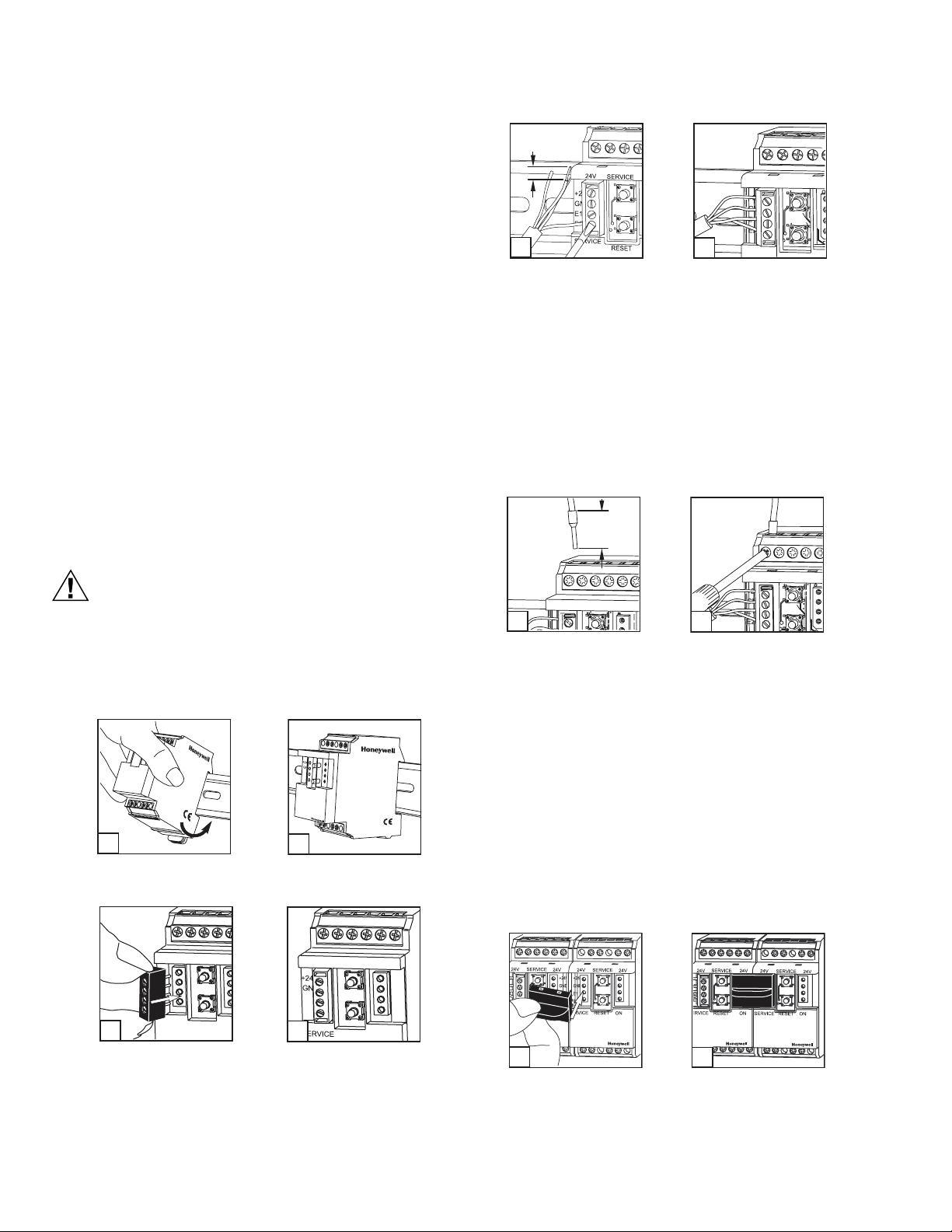
INSTALLATION
3. Prepare the cable for bus connection:
0.2 in.
(5 mm)
24V
3a
M25040
3b
a. Remove about 0.75 in. (2 cm) of the plastic cable
sheath.
b. Strip 0.2 in. (5 mm) insulation from each wire. Put a
wire end sleeve on stranded wires.
c. Insert the wire to the respective contact and secure
it by screwing down the contact screw.
d. Wire cross section of the 4 pole terminal block bus/
mains connection:
(1) Maximum 16 AWG (1.5 mm2) single wire.
(2) Maximum 18 AWG (1.0 mm
2
) stranded wire.
(3) Wire diameter minimum 28 AWG (0.3 mm) up to
16 AWG (1.4 mm).
4. Prepare cable for module connections.
0.3 in.
(7 mm)
SERVICE
M25064
CAUTION
Electrical installation and device termination shall
be accomplished by qualified persons only, by
respecting all applicable specifications and
regulations.
1. Power down the equipment. Mount the Extension mod-
ule on the DIN rail.
24V
SERV
IC
E
1b
2b
24V
+24V
GND
E1
E1
E2
E2
SERVICE
RESET
ON
M25061
24V
SERVICE
24V
+24V
ON
GND
E1
E2
M25063
E1
E2
RESET
SERVICE
ON
RESET
1a
M25060
2. Plug in the terminal block for bus connection.
24V
SERVICE
SERVICE
2a
RESET
M25062
24V
SERVICE
2
24V
SERVICE
24V
4a
M25041
4b
M25065
a. Strip the wires by 0.3 in. (7 mm). Put a wire end
sleeve on stranded wires.
b. Insert the wire into the respective module contact
and secure it by screwing down the contact screw
with a screwdriver.
c. Wire cross section of the 4 pole terminal block
bus/mains connection:
(1) Maximum 12 AWG (4.0 mm
(2) Maximum 14 AWG (2.5 mm
2
) single wire.
2
) stranded wire.
(3) Wire diameter: minimum 28 AWG (0.3 mm) up to
maximum 10 AWG (2.7 mm).
5. The module can be aligned without interspace. Use the
strapping plug to connect bus and supply voltage when
the modules are mounted in series. The modules can
be mounted in series without interspace. The maximum
number of modules connected in series is 15, with each
group needing an external power supply.
5a
+24V
GND
E1
E2
M25066
5b
+24V
GND
E1
E2
M25067
95-7717—2 2
Page 3

TERMINATION
Fig. 1 shows the termination points of the XIO-10HUB.
1728394105116
+24 V
GND
E1
E2
+24 V
GND
E1
E2
12
E2 E1 GND +24V
7
8
9
10
11
12
E2 E1 GND +24V
BUS Ub
Bus-Stecker max. 3 A
10 A
1
2
3
4
5
6
M25039
Max. 60 V
Fig. 1. Termination diagram for XIO-10HUB.
WIRING
Wiring of the XIO-10HUB must be accomplished in
accordance with federal, state, and local requirements.
Figures 2 through 4 show sample diagrams of wiring for the
XIO-10HUB.
COMPACT I/O MODULE
BUS Ub
E2 E1 GND +24V
7
8
9
10
Bus-Plug max. 3A
11
12
E2 E1 GND +24V
10 A
1
2
3
4
5
6
XIO-10HUB
04
85267 27072
Fig. 3. Side panel diagram of XIO-10HUB.
Max. 60V
M25072A
24V
+24V
GND
E1
E2
28394105116
1
24V
+24V
GND
E1
E2
+24V
GND
7
12
XIO-10HUB
M25071
Fig. 2. Front panel diagram of XIO-10HUB.
1
10 9 8 7 6 C
24V
+24V
GND
E1
E2
SERVICE ON
1019283746
24V
+24V
GND
1 2 3 4 5 6
24V
+24V
GND
E1
E1
E2
E2
Jumper
24V
+24V
GND
E1
E2
5
XIO-10DI
1 Each switch has two 14 AWG (2.5 mm2) connectors.
NOTE: ADDITIONAL WIRING POINTS, ONLY ONE WIRE /
CONNECTOR; ALSO FOR RELAY OUTPUT.
XIO-10HUB
M25073
Fig. 4. Wiring example XIO-10HUB used with XIO-10DI.
3 95-7717—2
Page 4

COMPACT I/O MODULE
By using this Honeywell literature, you agree that Honeywell will have no liability for any damages arising out of your use or modification to, the
literature. You will defend and indemnify Honeywell, its affiliates and subsidiaries, from and against any liability, cost, or damages, including
attorneys’ fees, arising out of, or resulting from, any modification to the literature by you.
Automation and Control Solutions
Honeywell International Inc. Honeywell Limited-Honeywell Limitée
1985 Douglas Drive North 35 Dynamic Drive
Golden Valley, MN 55422 Scarborough, Ontario M1V 4Z9
customer.honeywell.com
® U.S. Registered Trademark
© 2006 Honeywell International Inc.
95-7717—2 C.H Rev. 02-06
 Loading...